US5489139A - Parallel link seatpost suspension - Google Patents
Parallel link seatpost suspensionDownload PDFInfo
- Publication number
- US5489139A US5489139AUS08/430,760US43076095AUS5489139AUS 5489139 AUS5489139 AUS 5489139AUS 43076095 AUS43076095 AUS 43076095AUS 5489139 AUS5489139 AUS 5489139A
- Authority
- US
- United States
- Prior art keywords
- bicycle
- bracket
- leg
- arm
- hole
- Prior art date
- Legal status (The legal status is an assumption and is not a legal conclusion. Google has not performed a legal analysis and makes no representation as to the accuracy of the status listed.)
- Expired - Lifetime
Links
- 239000000725suspensionSubstances0.000titleclaimsabstractdescription23
- 238000003825pressingMethods0.000claims1
- 239000006096absorbing agentSubstances0.000description4
- 238000007373indentationMethods0.000description4
- 230000035939shockEffects0.000description4
- 229910000831SteelInorganic materials0.000description2
- XAGFODPZIPBFFR-UHFFFAOYSA-NaluminiumChemical compound[Al]XAGFODPZIPBFFR-UHFFFAOYSA-N0.000description2
- 229910052782aluminiumInorganic materials0.000description2
- 238000013461designMethods0.000description2
- 239000011435rockSubstances0.000description2
- 229910001220stainless steelInorganic materials0.000description2
- 239000010935stainless steelSubstances0.000description2
- 239000010959steelSubstances0.000description2
- 238000012546transferMethods0.000description2
- 238000012423maintenanceMethods0.000description1
- 238000000034methodMethods0.000description1
- 238000012986modificationMethods0.000description1
- 230000004048modificationEffects0.000description1
- 229920002635polyurethanePolymers0.000description1
- 239000004814polyurethaneSubstances0.000description1
- 239000012858resilient materialSubstances0.000description1
- 239000007787solidSubstances0.000description1
Images


Classifications
- B—PERFORMING OPERATIONS; TRANSPORTING
- B62—LAND VEHICLES FOR TRAVELLING OTHERWISE THAN ON RAILS
- B62J—CYCLE SADDLES OR SEATS; AUXILIARY DEVICES OR ACCESSORIES SPECIALLY ADAPTED TO CYCLES AND NOT OTHERWISE PROVIDED FOR, e.g. ARTICLE CARRIERS OR CYCLE PROTECTORS
- B62J1/00—Saddles or other seats for cycles; Arrangement thereof; Component parts
- B62J1/02—Saddles resiliently mounted on the frame; Equipment therefor, e.g. springs
- B62J1/06—Saddles capable of parallel motion up and down
- B62J1/065—Saddles supported on a parallelogram linkage
- B—PERFORMING OPERATIONS; TRANSPORTING
- B62—LAND VEHICLES FOR TRAVELLING OTHERWISE THAN ON RAILS
- B62J—CYCLE SADDLES OR SEATS; AUXILIARY DEVICES OR ACCESSORIES SPECIALLY ADAPTED TO CYCLES AND NOT OTHERWISE PROVIDED FOR, e.g. ARTICLE CARRIERS OR CYCLE PROTECTORS
- B62J1/00—Saddles or other seats for cycles; Arrangement thereof; Component parts
- B62J1/02—Saddles resiliently mounted on the frame; Equipment therefor, e.g. springs
- B62J1/04—Saddles capable of swinging about a horizontal pivot
Definitions
- the present inventionrelates to a suspension system for a bicycle or similar vehicle which cushions the rider from bumps.
- the inventionprovides a seatpost suspension system with an optimum direction of travel and which maintains necessary frame rigidity.
- motorcycle style suspension systemsinterpose a spring or shock absorber between either wheel or both wheels and the frame of the bicycle.
- the affected wheelmay move independently of the frame.
- the spring or shock absorberabsorbs at least some of the bump and prevents at least some of the wheel's bump induced movement from being transferred to the frame. Reduction in bicycle weight is a major goal of most modern cyclists.
- motorcycle style suspension systemsare inherently heavy.
- Sprung seat suspension systemsgenerally in, corporate one or more springs within the seat itself to cushion the rider from bumps.
- the springsare mounted vertically and allow the seat to bounce up and down.
- a more complicated systemallows the seat to rock forward and backward as well as to move up and down.
- the use of a sprung seatprecludes the use of other types of seats which the rider may prefer for different conditions.
- Sprung seatslack stability and a relatively rigid frame and seat are necessary for the efficient transfer of energy from the rider to the bicycle.
- Seatpost suspension systemsusually incorporate a spring or shock absorber within the seatpost of the bicycle. Ordinarily such systems allow an attached seat to move up and down along the axis of the seatpost. In operation, the rider moves up and down along this same axis in reaction to an encountered bump. Movement along this axis causes the distance between the pedals and the seat to vary which makes the transfer of energy from the rider to the bicycle less efficient.
- One of the objectives of the present inventionis to provide a simple, lightweight, and inexpensive seatpost suspension system for a bicycle. Another objective of the present invention is to provide a suspension system which maintains frame rigidity to a great extent. Another objective of the present invention is to provide a suspension system in which the distance from the seat to the pedals remains relatively constant. Maintenance of a level seat is important to rider comfort and efficiency. Another objective of the present invention is to provide a suspension system in which the top of the seat remains level when a bump is encountered. When the rear wheel of a bicycle hits a bump, the rear of the bicycle moves upward and forward, rotating about the front axle. This upward and forward direction is referred to as the direction of the bump force.
- the bicycle seatpost with an integrated suspension systemincludes a bracket which may be attached to the seatpost acceptor on a bicycle.
- the bottoms of two "L" shaped armsare attached by pivot pins to the bracket with one at the rear of the bracket and the other at the front.
- a saddle clamp baseis attached by pivot pins to the tops of the two "L” shaped arms.
- Means for attaching a conventional seatis provided on the top of the saddle clamp base.
- the "L" shaped armsform the rough shape of a parallelogram.
- the arms and the saddle clampmay move in an arc within the plane of the bicycle, pivoting on the pivot pins in the bracket. When the seat is near the top of the arc, the arms are at their greatest distance apart.
- a resilient meansis interposed between the arms tending to force the arms apart and the seat toward the top of the arc.
- the resilient meanscompresses, allowing the seat to rock downward and backward, generally moving in the opposite direction as the direction of the bump force.
- FIG. 1is a side view of a seatpost constructed in accordance with the invention
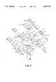
- FIG. 2is an exploded isometric view of a seatpost constructed in accordance with the invention.
- FIG. 3is a partial cross-sectional view of the seatpost shown in FIG. 2 taken along lines 3--3;
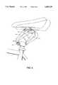
- FIG. 4is a side view of a seatpost constructed in accordance with the invention which shows the seatpost incorporated into a bicycle and the range of motion of the seatpost.
- the seatpost of the inventionis shown in a side view in FIG. 1.
- the bottom of a cylindrical post 2may be attached to the conventional seatpost receptor of a bicycle.
- a bracket 4includes a vertical opening 6 which fits over the top of post 2. There is a hole 8 perpendicular to the plane of the bicycle near the upper rear of bracket 4. There is another hole 10 also perpendicular to the plane of the bicycle near the lower front of bracket 4. There is a horizontal stop surface 12 on the forward top of bracket 4. The hole 10 is near the front of bracket 4, but rearward of stop surface 12.
- the bottom of a rear arm 16includes a notch 18 slightly wider than the rearward end of bracket 4.
- Notch 18fits over the rear of bracket 4.
- Rear arm 16is attached to bracket 4 by a pivot pin 22 which passes through hole 8 and holes 20.
- Pivot pin 22is held in place by a spring clip 24 which engages with a slot 26.
- a typical configuration of pins, spring clips, and slotsis shown in FIG. 3.
- the rear arm 16has the general shape of an "L” with the shorter end at the top and forming a leg 28 and the opening of the "L" facing forward.
- the leg 28has a notch 30 the same width as the notch 18.
- a saddle clamp base 34 having the general shape of a shallow "U”has a leg 36 at its rearward end and a leg 38 at its forward end. The width of leg 36 is slightly less than the width of notch 30.
- a hole 40 through leg 36is perpendicular to the plane of the bicycle.
- the saddle clamp base 34is attached to the rear arm 16 by a pivot pin 42 inserted through holes 32 and hole 40. The pivot pin 42 is held in place by a spring clip 44 which fits into a slot 46. There is a hole 48 perpendicular to the plane of the bicycle through leg 38.
- a front arm 50has the general shape of an "L” with the shorter end of the “L” forming a leg 52 at the bottom and with the opening of the "L” facing rearward.
- the rearward end of leg 52has a notch 54 slightly wider than the width of the forward end of bracket 4.
- Front arm 50is attached to the forward end of bracket 4 by a pivot pin 58 inserted through holes 56 and hole 10 in bracket 4. Pivot pin 58 is held in place by spring clip 60 which fits into slot 62.
- a stop pin 66is inserted through holes 64 and held in place by spring clip 68 engaged with slot 70.
- FIG. 2there is a notch 72 slightly wider than the width of leg 38 on saddle clamp base 34 at the upper end of front arm 50.
- Front arm 50is attached to saddle clamp base 34 by a pivot pin 76 inserted through holes 74 and hole 48 in leg 38. Pivot pin 76 is held in place by spring clip 78 engaged with a slot 80.
- FIG. 2there is a cylindrical indentation 82 near the bottom of the forward face of rear arm 16.
- FIG. 3there is a similar cylindrical indentation 84 near the top of the rearward face of front arm 50.
- a spring 86is interposed between rear arm 16 and front arm 50. The top of spring 86 fits within indentation 84 and the bottom of spring 86 fits within the indentation 82.
- a saddle bolt 88is inserted upward through a clamp slot 90 in the "U” shaped portion of saddle clamp base 34.
- a clamp barrel 92 with a “D” shaperests on the top surface of the "U” shape of the clamp base 34.
- the saddle bolt 88passes through barrel hole 94 in the clamp barrel 92.
- the saddle bolt 88screws into a clamp nut 96.
- the top surface of clamp barrel 92includes two saddle rail channels 98 which have the shape of a half cylinder.
- the saddle rail channels 98are on either side of the top surface of clamp barrel 92, are generally horizontal, and run parallel to the plane of the bicycle.
- the bottom surface of clamp nut 96includes two saddle rail channels 100 which mirror the saddle rail channels 98.
- Most conventional bicycle seatshave standard rails for mounting. Such a seat is mounted to the seatpost by placing the rails inside saddle rail channels 98 and saddle rail channels 100 and tightening saddle bolt 88. The saddle bolt 88 may be moved within clamp slot 90 before tightening to adjust the seat to the preferred position.
- the seatpost of the inventionis shown in operation in FIG. 4.
- the spring 86tends to force the rear arm 16 and the front arm 50 apart. Because of the configuration of the seatpost, this action tends to force the seatpost forward until stop pin 66 contacts stop surface 12.
- the seatpostcushions the impact by rocking rearward and downward generally moving in the opposite direction from the direction of the bump force.
- the seatpostdoes move in a rearward and downward direction, frame rigidity is maintained to a great extent because the design of the seatpost prevents the seat from moving out of the plane of the bicycle and prevents the seat from twisting.
- the design of the seatpostalso causes the distance from the seat to the pedals to remain relatively constant when a bump is encountered.
- the bracket 4, the rear arm 16, the front arm 50, and the saddle clamp base 34are made of machined aluminum; but stainless steel or the like could be used.
- the post 2is made of aluminum; but stainless steel or the like could be used.
- the post 2is glued to the bracket 4; but other fastening methods could be used.
- the spring 86is made of solid, cylindrical polyurethane, but a steel spring or other resilient material could be used.
- the other elements of the seatpostare made of steel.
Landscapes
- Engineering & Computer Science (AREA)
- Mechanical Engineering (AREA)
- Fluid-Damping Devices (AREA)
Abstract
Description
Claims (4)
Priority Applications (1)
| Application Number | Priority Date | Filing Date | Title |
|---|---|---|---|
| US08/430,760US5489139A (en) | 1995-04-27 | 1995-04-27 | Parallel link seatpost suspension |
Applications Claiming Priority (1)
| Application Number | Priority Date | Filing Date | Title |
|---|---|---|---|
| US08/430,760US5489139A (en) | 1995-04-27 | 1995-04-27 | Parallel link seatpost suspension |
Publications (1)
| Publication Number | Publication Date |
|---|---|
| US5489139Atrue US5489139A (en) | 1996-02-06 |
Family
ID=23708907
Family Applications (1)
| Application Number | Title | Priority Date | Filing Date |
|---|---|---|---|
| US08/430,760Expired - LifetimeUS5489139A (en) | 1995-04-27 | 1995-04-27 | Parallel link seatpost suspension |
Country Status (1)
| Country | Link |
|---|---|
| US (1) | US5489139A (en) |
Cited By (52)
| Publication number | Priority date | Publication date | Assignee | Title |
|---|---|---|---|---|
| US5702093A (en)* | 1996-11-05 | 1997-12-30 | Liao; Chi-Chao | Shock absorbing device for a bicycle seat |
| US5833255A (en)* | 1996-06-20 | 1998-11-10 | Team Vision | Bicycle seat suspension |
| US5915675A (en)* | 1997-09-10 | 1999-06-29 | Chen; Hui-Hsiung | Seat suspension device |
| US5921625A (en)* | 1997-03-05 | 1999-07-13 | Supima Holdings Inc. | Mounting structure for cycle seat |
| US5971477A (en)* | 1998-03-18 | 1999-10-26 | Bell; Dennis L. | Seating device |
| US6010188A (en)* | 1998-08-21 | 2000-01-04 | Yates; Paul M. | Bicycle saddle and suspension therefor |
| US6019422A (en)* | 1998-06-10 | 2000-02-01 | Taormino; Joseph S. | Laterally pivoting bicycle saddle mount with shock absorber |
| US6039396A (en)* | 1997-03-05 | 2000-03-21 | Supima Holdings Inc. | Bicycle seat and seat cover |
| US6073949A (en)* | 1998-09-01 | 2000-06-13 | Softride, Inc. | Slider beam suspension system for a bicycle seat |
| US6089656A (en)* | 1995-06-01 | 2000-07-18 | Hals-Lauritzen A/S | Spring-action seat suspension assembly for a two-wheeler |
| US6116683A (en)* | 1997-05-19 | 2000-09-12 | Maier; Dillon | Bicycle touring seat |
| US6161856A (en)* | 1998-11-13 | 2000-12-19 | Invacare Corporation | Wheelchair suspension system |
| US6164676A (en)* | 1998-02-20 | 2000-12-26 | Trek Bicycle Corporation | Variable reduction cross-linkage for rear suspension bicycle |
| US6203042B1 (en) | 1998-02-20 | 2001-03-20 | Trek Bicycle Corporation | Bicycle rear suspension system providing relative rearward motion of rear axle |
| US6270065B1 (en)* | 1998-06-05 | 2001-08-07 | Cato Hals Design As | Seat suspension assembly for a two-wheeler |
| US6276653B1 (en) | 1999-01-13 | 2001-08-21 | Walter S. Traxler | Seat suspension for a vehicle |
| US6409130B1 (en)* | 1999-09-01 | 2002-06-25 | Kevin L. Maret | Pivoting suspension seat post for a bicycle seat |
| US6565487B1 (en)* | 2000-07-17 | 2003-05-20 | Hai Pin Kuo | Exerciser having a forward and rearward adjusting seat |
| KR20040024801A (en)* | 2002-09-16 | 2004-03-22 | 김명희 | The device of lift system for bicycle saddle and handle |
| US20040090095A1 (en)* | 2002-09-19 | 2004-05-13 | Donald Jacobsmeyer | Bicycle seat |
| US20050225132A1 (en)* | 2004-03-29 | 2005-10-13 | Tisue Kevin C | Lightweight three-link cycle seat clamp |
| US20060244249A1 (en)* | 2002-10-25 | 2006-11-02 | Gerold Goertzen | Suspension for wheeled vehicles |
| US7144029B1 (en)* | 2003-10-30 | 2006-12-05 | Heady Steven R | Bicycle seat attachment |
| US20090091092A1 (en)* | 2001-10-10 | 2009-04-09 | Invacare Corporation | Wheelchair suspension |
| US20100013172A1 (en)* | 2000-10-27 | 2010-01-21 | Invacare Corporation | Obstacle traversing wheelchair |
| US20100084209A1 (en)* | 2007-02-08 | 2010-04-08 | Invacare Corporation | Wheelchair suspension |
| WO2010145085A1 (en)* | 2009-06-19 | 2010-12-23 | Chang Chia-Chang | Bicycle seat cushion |
| US20110163515A1 (en)* | 2010-01-06 | 2011-07-07 | Cusack Douglas A | Suspension bicycle seat post |
| EP2514659A1 (en)* | 2011-04-20 | 2012-10-24 | Marius Lötscher | Adjustment device for a bicycle saddle |
| US8297388B2 (en) | 2007-01-12 | 2012-10-30 | Invacare International Sarl | Wheelchair with suspension arms |
| US8573341B2 (en) | 2001-10-19 | 2013-11-05 | Invacare Corporation | Wheelchair suspension |
| US8888117B2 (en) | 2011-09-01 | 2014-11-18 | Cirrus Cycles, Inc. | Suspension systems and methods for bicycles |
| US8910975B2 (en) | 2007-02-14 | 2014-12-16 | Invacare Corporation | Wheelchair with suspension |
| US9010470B2 (en) | 2009-10-09 | 2015-04-21 | Invacare Corporation | Wheelchair suspension |
| US9308143B2 (en) | 2012-02-15 | 2016-04-12 | Invacare Corporation | Wheelchair suspension |
| US9896141B2 (en)* | 2016-03-08 | 2018-02-20 | Robert Austin | BikeSeatBoost power seat, fits all bicycles |
| US9950760B2 (en) | 2013-05-03 | 2018-04-24 | Redshift Sports Llc | Multiple position bicycle seat post |
| US10144469B2 (en)* | 2016-08-16 | 2018-12-04 | Shinji Marui | Bicycle saddle shape holder apparatus |
| US10450022B2 (en)* | 2018-01-31 | 2019-10-22 | David Watson | Device for adjusting a seat position of a bicycle seat |
| US10661848B2 (en)* | 2016-11-18 | 2020-05-26 | Ts Tech Co., Ltd. | Seat device |
| USD919486S1 (en)* | 2020-01-10 | 2021-05-18 | Cirrus Cycles, Inc. | Bicycle handlebar suspension |
| US20210300492A1 (en)* | 2020-03-26 | 2021-09-30 | Cane Creek Cycling Components, Inc. | Systems and methods of bicycle suspension |
| US11213441B2 (en) | 2002-10-25 | 2022-01-04 | Invacare Corporation | Suspension for wheeled vehicles |
| DE102020123061A1 (en) | 2020-09-03 | 2022-03-03 | Grammer Aktiengesellschaft | Spring element and vehicle seat with spring element |
| US11485437B2 (en) | 2020-11-19 | 2022-11-01 | Toyota Motor Engineering & Manufacturing North America, Inc. | Bicycle saddle with vibration isolators |
| US11565763B1 (en) | 2022-01-10 | 2023-01-31 | Toyota Motor Engineering & Manufacturing North America. Inc. | Bicycle saddle with spring-based vibration isolation |
| US11603153B1 (en)* | 2022-01-10 | 2023-03-14 | Toyota Motor Engineering & Manufacturing North America, Inc. | Bicycle saddle with super elastic material member activated vibration isolation |
| US11628898B1 (en) | 2022-01-10 | 2023-04-18 | Toyota Motor Engineering & Manufacturing North America, Inc. | Vibration isolation for bicycle saddle using super elastic material members |
| US11903887B2 (en) | 2020-02-25 | 2024-02-20 | Invacare Corporation | Wheelchair and suspension systems |
| WO2024137321A1 (en)* | 2022-12-19 | 2024-06-27 | Toyota Motor Engineering & Manufacturing North America, Inc. | Bicycle seat with vibration isolation |
| US12151757B2 (en) | 2018-04-03 | 2024-11-26 | Redshift Sports, LLC | Suspension seatpost with internal spring |
| US12403970B2 (en) | 2020-05-04 | 2025-09-02 | David Watson | Device for adjusting a seat position of a bicycle seat |
Citations (12)
| Publication number | Priority date | Publication date | Assignee | Title |
|---|---|---|---|---|
| DE152186C (en)* | ||||
| US239211A (en)* | 1881-03-22 | Ice-cream freezer | ||
| GB151915A (en)* | 1920-06-18 | 1920-10-07 | Frank Townshend | Improvements in pillion seats for motor cycles |
| GB154369A (en)* | 1919-09-11 | 1920-12-02 | Charles Herbert Lamb | Improvements in pillion seats for motor cycles, cycles, or the like |
| FR27505E (en)* | 1923-02-26 | 1924-07-28 | Suspension system applicable to saddles and seats of bicycles, motorcycles, agricultural machinery or tractors; motor vehicles or other | |
| GB265885A (en)* | 1926-10-06 | 1927-02-17 | Wittkop & Co Herforderstrasse | Saddle for bicycles, motor cycles and the like |
| GB474349A (en)* | 1937-04-23 | 1937-10-29 | Max Schubert | Improvements in or relating to cycle saddles |
| US2949153A (en)* | 1955-06-30 | 1960-08-16 | Hickman Ind Inc | Seat structure |
| US3314672A (en)* | 1965-05-10 | 1967-04-18 | Persson Bror Gote | Resilient support for seats, especially for motor vehicles |
| US4456295A (en)* | 1981-11-12 | 1984-06-26 | Francu Nicholas J | Bicycle seat adapter |
| US4736983A (en)* | 1986-11-26 | 1988-04-12 | Furbee Raymond D | Shock absorber for a bicycle seat |
| US5044648A (en)* | 1989-04-18 | 1991-09-03 | Knapp Thomas D | Bicycle suspension system |
- 1995
- 1995-04-27USUS08/430,760patent/US5489139A/ennot_activeExpired - Lifetime
Patent Citations (12)
| Publication number | Priority date | Publication date | Assignee | Title |
|---|---|---|---|---|
| DE152186C (en)* | ||||
| US239211A (en)* | 1881-03-22 | Ice-cream freezer | ||
| GB154369A (en)* | 1919-09-11 | 1920-12-02 | Charles Herbert Lamb | Improvements in pillion seats for motor cycles, cycles, or the like |
| GB151915A (en)* | 1920-06-18 | 1920-10-07 | Frank Townshend | Improvements in pillion seats for motor cycles |
| FR27505E (en)* | 1923-02-26 | 1924-07-28 | Suspension system applicable to saddles and seats of bicycles, motorcycles, agricultural machinery or tractors; motor vehicles or other | |
| GB265885A (en)* | 1926-10-06 | 1927-02-17 | Wittkop & Co Herforderstrasse | Saddle for bicycles, motor cycles and the like |
| GB474349A (en)* | 1937-04-23 | 1937-10-29 | Max Schubert | Improvements in or relating to cycle saddles |
| US2949153A (en)* | 1955-06-30 | 1960-08-16 | Hickman Ind Inc | Seat structure |
| US3314672A (en)* | 1965-05-10 | 1967-04-18 | Persson Bror Gote | Resilient support for seats, especially for motor vehicles |
| US4456295A (en)* | 1981-11-12 | 1984-06-26 | Francu Nicholas J | Bicycle seat adapter |
| US4736983A (en)* | 1986-11-26 | 1988-04-12 | Furbee Raymond D | Shock absorber for a bicycle seat |
| US5044648A (en)* | 1989-04-18 | 1991-09-03 | Knapp Thomas D | Bicycle suspension system |
Non-Patent Citations (8)
| Title |
|---|
| "Bike" magazine article Softride Contour Mar. 1994, two pp. 64 and 65. |
| "Bike" magazine article Ten Underrated Products You Probably Don't Own But Maybe Should (in part) Jan. 1994, two pp. 82 and 83. |
| "Mountain Bike Action" picture and caption describing Body Shock, Jan. 1994, one p. 48. |
| "Mountain Bike" magazine advertisement for Power Post, Jun., 1994, one p. 26. |
| Bike magazine article Softride Contour Mar. 1994, two pp. 64 and 65.* |
| Bike magazine article Ten Underrated Products You Probably Don t Own But Maybe Should (in part) Jan. 1994, two pp. 82 and 83.* |
| Mountain Bike Action picture and caption describing Body Shock, Jan. 1994, one p. 48.* |
| Mountain Bike magazine advertisement for Power Post, Jun., 1994, one p. 26.* |
Cited By (93)
| Publication number | Priority date | Publication date | Assignee | Title |
|---|---|---|---|---|
| US6089656A (en)* | 1995-06-01 | 2000-07-18 | Hals-Lauritzen A/S | Spring-action seat suspension assembly for a two-wheeler |
| US5833255A (en)* | 1996-06-20 | 1998-11-10 | Team Vision | Bicycle seat suspension |
| US5702093A (en)* | 1996-11-05 | 1997-12-30 | Liao; Chi-Chao | Shock absorbing device for a bicycle seat |
| US5921625A (en)* | 1997-03-05 | 1999-07-13 | Supima Holdings Inc. | Mounting structure for cycle seat |
| US6039396A (en)* | 1997-03-05 | 2000-03-21 | Supima Holdings Inc. | Bicycle seat and seat cover |
| US6116683A (en)* | 1997-05-19 | 2000-09-12 | Maier; Dillon | Bicycle touring seat |
| US5915675A (en)* | 1997-09-10 | 1999-06-29 | Chen; Hui-Hsiung | Seat suspension device |
| US6203042B1 (en) | 1998-02-20 | 2001-03-20 | Trek Bicycle Corporation | Bicycle rear suspension system providing relative rearward motion of rear axle |
| US6164676A (en)* | 1998-02-20 | 2000-12-26 | Trek Bicycle Corporation | Variable reduction cross-linkage for rear suspension bicycle |
| US5971477A (en)* | 1998-03-18 | 1999-10-26 | Bell; Dennis L. | Seating device |
| US6270065B1 (en)* | 1998-06-05 | 2001-08-07 | Cato Hals Design As | Seat suspension assembly for a two-wheeler |
| US6019422A (en)* | 1998-06-10 | 2000-02-01 | Taormino; Joseph S. | Laterally pivoting bicycle saddle mount with shock absorber |
| US6010188A (en)* | 1998-08-21 | 2000-01-04 | Yates; Paul M. | Bicycle saddle and suspension therefor |
| US6073949A (en)* | 1998-09-01 | 2000-06-13 | Softride, Inc. | Slider beam suspension system for a bicycle seat |
| US6161856A (en)* | 1998-11-13 | 2000-12-19 | Invacare Corporation | Wheelchair suspension system |
| US6425597B1 (en)* | 1998-11-13 | 2002-07-30 | Invacare Corporation | Lightweight wheelchair frame |
| US6276653B1 (en) | 1999-01-13 | 2001-08-21 | Walter S. Traxler | Seat suspension for a vehicle |
| US6409130B1 (en)* | 1999-09-01 | 2002-06-25 | Kevin L. Maret | Pivoting suspension seat post for a bicycle seat |
| US6565487B1 (en)* | 2000-07-17 | 2003-05-20 | Hai Pin Kuo | Exerciser having a forward and rearward adjusting seat |
| US9987177B2 (en) | 2000-10-27 | 2018-06-05 | Invacare Corporation | Obstacle traversing wheelchair |
| US9149398B2 (en) | 2000-10-27 | 2015-10-06 | Invacare Corporation | Obstacle traversing wheelchair |
| US20100013172A1 (en)* | 2000-10-27 | 2010-01-21 | Invacare Corporation | Obstacle traversing wheelchair |
| US8172016B2 (en) | 2000-10-27 | 2012-05-08 | Invacare Corporation | Obstacle traversing wheelchair |
| US9370455B2 (en) | 2001-10-10 | 2016-06-21 | Invacare Corporation | Wheelchair suspension |
| US20090091092A1 (en)* | 2001-10-10 | 2009-04-09 | Invacare Corporation | Wheelchair suspension |
| US8172015B2 (en) | 2001-10-10 | 2012-05-08 | Invacare Corporation | Wheelchair suspension |
| US8925943B2 (en) | 2001-10-10 | 2015-01-06 | Invacare Corp. | Wheelchair suspension |
| US8573341B2 (en) | 2001-10-19 | 2013-11-05 | Invacare Corporation | Wheelchair suspension |
| KR20040024801A (en)* | 2002-09-16 | 2004-03-22 | 김명희 | The device of lift system for bicycle saddle and handle |
| US20040090095A1 (en)* | 2002-09-19 | 2004-05-13 | Donald Jacobsmeyer | Bicycle seat |
| US6755464B2 (en)* | 2002-09-19 | 2004-06-29 | Donald Jacobsmeyer | Bicycle seat |
| US20060244249A1 (en)* | 2002-10-25 | 2006-11-02 | Gerold Goertzen | Suspension for wheeled vehicles |
| US9364377B2 (en) | 2002-10-25 | 2016-06-14 | Invacare Corporation | Suspension for wheeled vehicles |
| US11213441B2 (en) | 2002-10-25 | 2022-01-04 | Invacare Corporation | Suspension for wheeled vehicles |
| US8534679B2 (en) | 2002-10-25 | 2013-09-17 | Invacare Corporation | Suspension for wheeled vehicles |
| US9925100B2 (en) | 2002-10-25 | 2018-03-27 | Invacare Corporation | Suspension for wheeled vehicles |
| US10512572B2 (en) | 2002-10-25 | 2019-12-24 | Invacare Corporation | Suspension for wheeled vehicles |
| US7144029B1 (en)* | 2003-10-30 | 2006-12-05 | Heady Steven R | Bicycle seat attachment |
| US20100007182A1 (en)* | 2004-03-29 | 2010-01-14 | Tisue Kevin Christipher | lightweight Three-Link Cycle Seat Clamp |
| US8007041B2 (en)* | 2004-03-29 | 2011-08-30 | Kevin Tisue | Lightweight three-link cycle seat clamp |
| US20050225132A1 (en)* | 2004-03-29 | 2005-10-13 | Tisue Kevin C | Lightweight three-link cycle seat clamp |
| US8297388B2 (en) | 2007-01-12 | 2012-10-30 | Invacare International Sarl | Wheelchair with suspension arms |
| US10912690B2 (en) | 2007-02-08 | 2021-02-09 | Invacare Corporation | Wheelchair suspension |
| US20100084209A1 (en)* | 2007-02-08 | 2010-04-08 | Invacare Corporation | Wheelchair suspension |
| US10265229B2 (en) | 2007-02-08 | 2019-04-23 | Invacare Corporation | Wheelchair suspension |
| US8794359B2 (en) | 2007-02-08 | 2014-08-05 | Invacare Corporation | Wheelchair suspension |
| US11819464B2 (en) | 2007-02-08 | 2023-11-21 | Invacare Corporation | Wheelchair suspension |
| US9603762B2 (en) | 2007-02-08 | 2017-03-28 | Invacare Corporation | Wheelchair suspension |
| US8272461B2 (en) | 2007-02-08 | 2012-09-25 | Invacare Corporation | Wheelchair suspension |
| US11464687B2 (en) | 2007-02-08 | 2022-10-11 | Invacare Coporation | Wheelchair suspension |
| US9346335B2 (en) | 2007-02-14 | 2016-05-24 | Invacare Corporation | Stability control system |
| US9827823B2 (en) | 2007-02-14 | 2017-11-28 | Invacare Corporation | Stability control system |
| US10532626B2 (en) | 2007-02-14 | 2020-01-14 | Invacare Corporation | Stability control system |
| US11850906B2 (en) | 2007-02-14 | 2023-12-26 | Invacare Corporation | Stability control system |
| US11097589B2 (en) | 2007-02-14 | 2021-08-24 | Invacare Corporation | Stability control system |
| US8910975B2 (en) | 2007-02-14 | 2014-12-16 | Invacare Corporation | Wheelchair with suspension |
| US11535078B2 (en) | 2007-02-14 | 2022-12-27 | Invacare Corporation | Stability control system |
| WO2010145085A1 (en)* | 2009-06-19 | 2010-12-23 | Chang Chia-Chang | Bicycle seat cushion |
| US9010470B2 (en) | 2009-10-09 | 2015-04-21 | Invacare Corporation | Wheelchair suspension |
| US9913768B2 (en) | 2009-10-09 | 2018-03-13 | Invacare Corporation | Wheelchair suspension |
| US11857470B2 (en) | 2009-10-09 | 2024-01-02 | Invacare Corporation | Wheelchair suspension |
| US11096845B2 (en) | 2009-10-09 | 2021-08-24 | Invacare Corporation | Wheelchair suspension |
| US20110163515A1 (en)* | 2010-01-06 | 2011-07-07 | Cusack Douglas A | Suspension bicycle seat post |
| US8042823B2 (en) | 2010-01-06 | 2011-10-25 | Trek Bicycle Corporation | Suspension bicycle seat post |
| EP2514659A1 (en)* | 2011-04-20 | 2012-10-24 | Marius Lötscher | Adjustment device for a bicycle saddle |
| US8888117B2 (en) | 2011-09-01 | 2014-11-18 | Cirrus Cycles, Inc. | Suspension systems and methods for bicycles |
| US10434019B2 (en) | 2012-02-15 | 2019-10-08 | Invacare Corporation | Wheelchair suspension |
| US9308143B2 (en) | 2012-02-15 | 2016-04-12 | Invacare Corporation | Wheelchair suspension |
| US11234875B2 (en) | 2012-02-15 | 2022-02-01 | Invacare Corporation | Wheelchair suspension |
| US9700470B2 (en) | 2012-02-15 | 2017-07-11 | Invacare Corporation | Wheelchair suspension |
| US9950760B2 (en) | 2013-05-03 | 2018-04-24 | Redshift Sports Llc | Multiple position bicycle seat post |
| US9896141B2 (en)* | 2016-03-08 | 2018-02-20 | Robert Austin | BikeSeatBoost power seat, fits all bicycles |
| US10144469B2 (en)* | 2016-08-16 | 2018-12-04 | Shinji Marui | Bicycle saddle shape holder apparatus |
| US10661848B2 (en)* | 2016-11-18 | 2020-05-26 | Ts Tech Co., Ltd. | Seat device |
| US12162553B2 (en)* | 2018-01-31 | 2024-12-10 | David Watson | Device for adjusting a seat position of a bicycle seat |
| US20210031851A1 (en)* | 2018-01-31 | 2021-02-04 | Greenroom Holdings Ltd. | Device for adjusting a seat position of a bicycle seat |
| US10450022B2 (en)* | 2018-01-31 | 2019-10-22 | David Watson | Device for adjusting a seat position of a bicycle seat |
| US12151757B2 (en) | 2018-04-03 | 2024-11-26 | Redshift Sports, LLC | Suspension seatpost with internal spring |
| USD919486S1 (en)* | 2020-01-10 | 2021-05-18 | Cirrus Cycles, Inc. | Bicycle handlebar suspension |
| US11903887B2 (en) | 2020-02-25 | 2024-02-20 | Invacare Corporation | Wheelchair and suspension systems |
| WO2021194627A1 (en)* | 2020-03-26 | 2021-09-30 | Cane Creek Cycling Components, Inc. | Systems and methods of bicycle suspension |
| US11673621B2 (en)* | 2020-03-26 | 2023-06-13 | Cane Creek Cycling Components, Inc. | Systems and methods of bicycle suspension |
| US20210300492A1 (en)* | 2020-03-26 | 2021-09-30 | Cane Creek Cycling Components, Inc. | Systems and methods of bicycle suspension |
| US12403970B2 (en) | 2020-05-04 | 2025-09-02 | David Watson | Device for adjusting a seat position of a bicycle seat |
| US11794617B2 (en) | 2020-09-03 | 2023-10-24 | Grammer Ag | Spring element and vehicle seat having a spring element |
| DE102020123061B4 (en) | 2020-09-03 | 2024-02-08 | Grammer Aktiengesellschaft | Spring element and vehicle seat with spring element |
| EP3964387A1 (en)* | 2020-09-03 | 2022-03-09 | Grammer Ag | Spring element and vehicle seat with spring element |
| DE102020123061A1 (en) | 2020-09-03 | 2022-03-03 | Grammer Aktiengesellschaft | Spring element and vehicle seat with spring element |
| US11485437B2 (en) | 2020-11-19 | 2022-11-01 | Toyota Motor Engineering & Manufacturing North America, Inc. | Bicycle saddle with vibration isolators |
| US11628898B1 (en) | 2022-01-10 | 2023-04-18 | Toyota Motor Engineering & Manufacturing North America, Inc. | Vibration isolation for bicycle saddle using super elastic material members |
| US11603153B1 (en)* | 2022-01-10 | 2023-03-14 | Toyota Motor Engineering & Manufacturing North America, Inc. | Bicycle saddle with super elastic material member activated vibration isolation |
| US11565763B1 (en) | 2022-01-10 | 2023-01-31 | Toyota Motor Engineering & Manufacturing North America. Inc. | Bicycle saddle with spring-based vibration isolation |
| WO2024137321A1 (en)* | 2022-12-19 | 2024-06-27 | Toyota Motor Engineering & Manufacturing North America, Inc. | Bicycle seat with vibration isolation |
Similar Documents
| Publication | Publication Date | Title |
|---|---|---|
| US5489139A (en) | Parallel link seatpost suspension | |
| EP1698549B1 (en) | Bicycle with rear suspension | |
| US6843494B2 (en) | Rear suspension system for two-wheeled vehicles, particularly bicycles | |
| US5611557A (en) | Bicycle suspension system | |
| US5725227A (en) | Suspension system for a bicycle | |
| US7467803B2 (en) | Rear suspension system for bicycles | |
| US5205572A (en) | Cycle rear suspension system | |
| US5749590A (en) | Suspension fork assembly | |
| US6450521B1 (en) | Suspension system for a vehicle | |
| US6089656A (en) | Spring-action seat suspension assembly for a two-wheeler | |
| US20040061305A1 (en) | Rear wheel suspension system for a bicycle | |
| US5553880A (en) | Energy-absorber for a bicycle frame | |
| WO1993003953A1 (en) | Cycle rear suspension system | |
| EP0419627A1 (en) | Combination beam seat support. | |
| US20060081407A1 (en) | Front suspension for recreational vehicle | |
| US6575485B2 (en) | Suspension system for a bicycle trailer | |
| US6073949A (en) | Slider beam suspension system for a bicycle seat | |
| US20080203699A1 (en) | Handlebar mount shock absorber structure | |
| US5911473A (en) | Bicycle saddle | |
| US6837506B2 (en) | Bicycle frame | |
| WO2021262015A1 (en) | Variable-geometry bicycle frame and method for dynamic changes to the geometry of a bicycle frame | |
| US20050066766A1 (en) | Handlebar mount shock absorber structure | |
| US5271635A (en) | Chainless bicycle having a front wheel resilient suspension | |
| US5762354A (en) | Cycle rear suspension system | |
| EP0669247A1 (en) | Rear suspension frame for two-wheeled vehicles |
Legal Events
| Date | Code | Title | Description |
|---|---|---|---|
| FEPP | Fee payment procedure | Free format text:PAYOR NUMBER ASSIGNED (ORIGINAL EVENT CODE: ASPN); ENTITY STATUS OF PATENT OWNER: SMALL ENTITY | |
| FEPP | Fee payment procedure | Free format text:PAYER NUMBER DE-ASSIGNED (ORIGINAL EVENT CODE: RMPN); ENTITY STATUS OF PATENT OWNER: SMALL ENTITY Free format text:PAYOR NUMBER ASSIGNED (ORIGINAL EVENT CODE: ASPN); ENTITY STATUS OF PATENT OWNER: SMALL ENTITY | |
| FPAY | Fee payment | Year of fee payment:4 | |
| REMI | Maintenance fee reminder mailed | ||
| FEPP | Fee payment procedure | Free format text:PETITION RELATED TO MAINTENANCE FEES FILED (ORIGINAL EVENT CODE: PMFP); ENTITY STATUS OF PATENT OWNER: SMALL ENTITY | |
| FEPP | Fee payment procedure | Free format text:PETITION RELATED TO MAINTENANCE FEES FILED (ORIGINAL EVENT CODE: PMFP); ENTITY STATUS OF PATENT OWNER: SMALL ENTITY | |
| FEPP | Fee payment procedure | Free format text:PETITION RELATED TO MAINTENANCE FEES GRANTED (ORIGINAL EVENT CODE: PMFG); ENTITY STATUS OF PATENT OWNER: SMALL ENTITY | |
| REIN | Reinstatement after maintenance fee payment confirmed | ||
| FPAY | Fee payment | Year of fee payment:8 | |
| SULP | Surcharge for late payment | ||
| FP | Lapsed due to failure to pay maintenance fee | Effective date:20040206 | |
| SULP | Surcharge for late payment | ||
| PRDP | Patent reinstated due to the acceptance of a late maintenance fee | Effective date:20040802 | |
| REMI | Maintenance fee reminder mailed | ||
| FEPP | Fee payment procedure | Free format text:PETITION RELATED TO MAINTENANCE FEES FILED (ORIGINAL EVENT CODE: PMFP); ENTITY STATUS OF PATENT OWNER: SMALL ENTITY | |
| FEPP | Fee payment procedure | Free format text:PETITION RELATED TO MAINTENANCE FEES GRANTED (ORIGINAL EVENT CODE: PMFG); ENTITY STATUS OF PATENT OWNER: SMALL ENTITY | |
| REIN | Reinstatement after maintenance fee payment confirmed | ||
| FPAY | Fee payment | Year of fee payment:12 | |
| SULP | Surcharge for late payment | ||
| FP | Lapsed due to failure to pay maintenance fee | Effective date:20080206 | |
| PRDP | Patent reinstated due to the acceptance of a late maintenance fee | Effective date:20080609 | |
| STCF | Information on status: patent grant | Free format text:PATENTED CASE |