US5488862A - Monolithic silicon rate-gyro with integrated sensors - Google Patents
Monolithic silicon rate-gyro with integrated sensorsDownload PDFInfo
- Publication number
- US5488862A US5488862AUS08/208,424US20842494AUS5488862AUS 5488862 AUS5488862 AUS 5488862AUS 20842494 AUS20842494 AUS 20842494AUS 5488862 AUS5488862 AUS 5488862A
- Authority
- US
- United States
- Prior art keywords
- silicon
- hinges
- axis
- frame
- defining
- Prior art date
- Legal status (The legal status is an assumption and is not a legal conclusion. Google has not performed a legal analysis and makes no representation as to the accuracy of the status listed.)
- Expired - Fee Related
Links
- 229910052710siliconInorganic materials0.000titleclaimsabstractdescription52
- 239000010703siliconSubstances0.000titleclaimsabstractdescription52
- XUIMIQQOPSSXEZ-UHFFFAOYSA-NSiliconChemical compound[Si]XUIMIQQOPSSXEZ-UHFFFAOYSA-N0.000titleclaimsdescription51
- 229910021421monocrystalline siliconInorganic materials0.000claimsabstractdescription10
- 239000013078crystalSubstances0.000claimsdescription3
- 238000005452bendingMethods0.000claimsdescription2
- 238000002955isolationMethods0.000claimsdescription2
- 230000035945sensitivityEffects0.000abstractdescription13
- 230000010355oscillationEffects0.000abstractdescription8
- 230000010354integrationEffects0.000abstractdescription2
- 235000012431wafersNutrition0.000description28
- 239000000463materialSubstances0.000description22
- 238000000034methodMethods0.000description10
- 230000001133accelerationEffects0.000description8
- 230000000694effectsEffects0.000description6
- ZOXJGFHDIHLPTG-UHFFFAOYSA-NBoronChemical compound[B]ZOXJGFHDIHLPTG-UHFFFAOYSA-N0.000description5
- 229910052796boronInorganic materials0.000description5
- 238000005530etchingMethods0.000description5
- 230000002829reductive effectEffects0.000description5
- VYPSYNLAJGMNEJ-UHFFFAOYSA-Nsilicon dioxideInorganic materialsO=[Si]=OVYPSYNLAJGMNEJ-UHFFFAOYSA-N0.000description5
- 230000008859changeEffects0.000description4
- 238000006880cross-coupling reactionMethods0.000description4
- 230000005284excitationEffects0.000description4
- 230000003993interactionEffects0.000description4
- 238000004519manufacturing processMethods0.000description4
- 238000009966trimmingMethods0.000description4
- 235000012239silicon dioxideNutrition0.000description3
- 238000001228spectrumMethods0.000description3
- 238000005482strain hardeningMethods0.000description3
- 239000000758substrateSubstances0.000description3
- 230000008901benefitEffects0.000description2
- 230000008021depositionEffects0.000description2
- 238000000866electrolytic etchingMethods0.000description2
- 238000005516engineering processMethods0.000description2
- PCHJSUWPFVWCPO-UHFFFAOYSA-NgoldChemical compound[Au]PCHJSUWPFVWCPO-UHFFFAOYSA-N0.000description2
- 239000010931goldSubstances0.000description2
- 229910052737goldInorganic materials0.000description2
- 239000012212insulatorSubstances0.000description2
- 238000005459micromachiningMethods0.000description2
- 239000000377silicon dioxideSubstances0.000description2
- 230000006641stabilisationEffects0.000description2
- 238000011105stabilizationMethods0.000description2
- ZAMOUSCENKQFHK-UHFFFAOYSA-NChlorine atomChemical compound[Cl]ZAMOUSCENKQFHK-UHFFFAOYSA-N0.000description1
- 229910000831SteelInorganic materials0.000description1
- 229910052782aluminiumInorganic materials0.000description1
- XAGFODPZIPBFFR-UHFFFAOYSA-NaluminiumChemical compound[Al]XAGFODPZIPBFFR-UHFFFAOYSA-N0.000description1
- 238000006243chemical reactionMethods0.000description1
- 229910052801chlorineInorganic materials0.000description1
- 239000000460chlorineSubstances0.000description1
- 238000013016dampingMethods0.000description1
- 230000001419dependent effectEffects0.000description1
- 238000001514detection methodMethods0.000description1
- 238000006073displacement reactionMethods0.000description1
- 230000009977dual effectEffects0.000description1
- 239000002305electric materialSubstances0.000description1
- 230000005686electrostatic fieldEffects0.000description1
- 230000008030eliminationEffects0.000description1
- 238000003379elimination reactionMethods0.000description1
- 238000002347injectionMethods0.000description1
- 239000007924injectionSubstances0.000description1
- 230000002452interceptive effectEffects0.000description1
- 238000001459lithographyMethods0.000description1
- 230000007246mechanismEffects0.000description1
- 229910052751metalInorganic materials0.000description1
- 239000002184metalSubstances0.000description1
- 238000012544monitoring processMethods0.000description1
- 150000004767nitridesChemical class0.000description1
- 230000003071parasitic effectEffects0.000description1
- 230000036961partial effectEffects0.000description1
- 238000000059patterningMethods0.000description1
- 230000000737periodic effectEffects0.000description1
- 230000008569processEffects0.000description1
- 239000010453quartzSubstances0.000description1
- 230000009467reductionEffects0.000description1
- 230000002441reversible effectEffects0.000description1
- 239000004065semiconductorSubstances0.000description1
- 230000035939shockEffects0.000description1
- 239000002210silicon-based materialSubstances0.000description1
- 238000004088simulationMethods0.000description1
- 239000007787solidSubstances0.000description1
- 239000000243solutionSubstances0.000description1
- 239000007858starting materialSubstances0.000description1
- 230000003068static effectEffects0.000description1
- 239000010959steelSubstances0.000description1
- 238000012876topographyMethods0.000description1
- 230000001052transient effectEffects0.000description1
- 238000004804windingMethods0.000description1
Images

Classifications
- G—PHYSICS
- G01—MEASURING; TESTING
- G01P—MEASURING LINEAR OR ANGULAR SPEED, ACCELERATION, DECELERATION, OR SHOCK; INDICATING PRESENCE, ABSENCE, OR DIRECTION, OF MOVEMENT
- G01P15/00—Measuring acceleration; Measuring deceleration; Measuring shock, i.e. sudden change of acceleration
- G01P15/02—Measuring acceleration; Measuring deceleration; Measuring shock, i.e. sudden change of acceleration by making use of inertia forces using solid seismic masses
- G01P15/08—Measuring acceleration; Measuring deceleration; Measuring shock, i.e. sudden change of acceleration by making use of inertia forces using solid seismic masses with conversion into electric or magnetic values
- G01P15/13—Measuring acceleration; Measuring deceleration; Measuring shock, i.e. sudden change of acceleration by making use of inertia forces using solid seismic masses with conversion into electric or magnetic values by measuring the force required to restore a proofmass subjected to inertial forces to a null position
- G01P15/132—Measuring acceleration; Measuring deceleration; Measuring shock, i.e. sudden change of acceleration by making use of inertia forces using solid seismic masses with conversion into electric or magnetic values by measuring the force required to restore a proofmass subjected to inertial forces to a null position with electromagnetic counterbalancing means
- G—PHYSICS
- G01—MEASURING; TESTING
- G01C—MEASURING DISTANCES, LEVELS OR BEARINGS; SURVEYING; NAVIGATION; GYROSCOPIC INSTRUMENTS; PHOTOGRAMMETRY OR VIDEOGRAMMETRY
- G01C19/00—Gyroscopes; Turn-sensitive devices using vibrating masses; Turn-sensitive devices without moving masses; Measuring angular rate using gyroscopic effects
- G01C19/56—Turn-sensitive devices using vibrating masses, e.g. vibratory angular rate sensors based on Coriolis forces
- G01C19/5719—Turn-sensitive devices using vibrating masses, e.g. vibratory angular rate sensors based on Coriolis forces using planar vibrating masses driven in a translation vibration along an axis
- G—PHYSICS
- G02—OPTICS
- G02B—OPTICAL ELEMENTS, SYSTEMS OR APPARATUS
- G02B26/00—Optical devices or arrangements for the control of light using movable or deformable optical elements
- G02B26/08—Optical devices or arrangements for the control of light using movable or deformable optical elements for controlling the direction of light
- G02B26/0816—Optical devices or arrangements for the control of light using movable or deformable optical elements for controlling the direction of light by means of one or more reflecting elements
- G02B26/0833—Optical devices or arrangements for the control of light using movable or deformable optical elements for controlling the direction of light by means of one or more reflecting elements the reflecting element being a micromechanical device, e.g. a MEMS mirror, DMD
- G02B26/0841—Optical devices or arrangements for the control of light using movable or deformable optical elements for controlling the direction of light by means of one or more reflecting elements the reflecting element being a micromechanical device, e.g. a MEMS mirror, DMD the reflecting element being moved or deformed by electrostatic means
- G—PHYSICS
- G02—OPTICS
- G02B—OPTICAL ELEMENTS, SYSTEMS OR APPARATUS
- G02B26/00—Optical devices or arrangements for the control of light using movable or deformable optical elements
- G02B26/08—Optical devices or arrangements for the control of light using movable or deformable optical elements for controlling the direction of light
- G02B26/0816—Optical devices or arrangements for the control of light using movable or deformable optical elements for controlling the direction of light by means of one or more reflecting elements
- G02B26/0833—Optical devices or arrangements for the control of light using movable or deformable optical elements for controlling the direction of light by means of one or more reflecting elements the reflecting element being a micromechanical device, e.g. a MEMS mirror, DMD
- G02B26/085—Optical devices or arrangements for the control of light using movable or deformable optical elements for controlling the direction of light by means of one or more reflecting elements the reflecting element being a micromechanical device, e.g. a MEMS mirror, DMD the reflecting means being moved or deformed by electromagnetic means
- G—PHYSICS
- G02—OPTICS
- G02B—OPTICAL ELEMENTS, SYSTEMS OR APPARATUS
- G02B26/00—Optical devices or arrangements for the control of light using movable or deformable optical elements
- G02B26/08—Optical devices or arrangements for the control of light using movable or deformable optical elements for controlling the direction of light
- G02B26/0816—Optical devices or arrangements for the control of light using movable or deformable optical elements for controlling the direction of light by means of one or more reflecting elements
- G02B26/0833—Optical devices or arrangements for the control of light using movable or deformable optical elements for controlling the direction of light by means of one or more reflecting elements the reflecting element being a micromechanical device, e.g. a MEMS mirror, DMD
- G02B26/0858—Optical devices or arrangements for the control of light using movable or deformable optical elements for controlling the direction of light by means of one or more reflecting elements the reflecting element being a micromechanical device, e.g. a MEMS mirror, DMD the reflecting means being moved or deformed by piezoelectric means
- G—PHYSICS
- G02—OPTICS
- G02B—OPTICAL ELEMENTS, SYSTEMS OR APPARATUS
- G02B26/00—Optical devices or arrangements for the control of light using movable or deformable optical elements
- G02B26/08—Optical devices or arrangements for the control of light using movable or deformable optical elements for controlling the direction of light
- G02B26/10—Scanning systems
- G02B26/101—Scanning systems with both horizontal and vertical deflecting means, e.g. raster or XY scanners
- G—PHYSICS
- G01—MEASURING; TESTING
- G01P—MEASURING LINEAR OR ANGULAR SPEED, ACCELERATION, DECELERATION, OR SHOCK; INDICATING PRESENCE, ABSENCE, OR DIRECTION, OF MOVEMENT
- G01P15/00—Measuring acceleration; Measuring deceleration; Measuring shock, i.e. sudden change of acceleration
- G01P15/02—Measuring acceleration; Measuring deceleration; Measuring shock, i.e. sudden change of acceleration by making use of inertia forces using solid seismic masses
- G01P15/08—Measuring acceleration; Measuring deceleration; Measuring shock, i.e. sudden change of acceleration by making use of inertia forces using solid seismic masses with conversion into electric or magnetic values
- G01P2015/0805—Measuring acceleration; Measuring deceleration; Measuring shock, i.e. sudden change of acceleration by making use of inertia forces using solid seismic masses with conversion into electric or magnetic values being provided with a particular type of spring-mass-system for defining the displacement of a seismic mass due to an external acceleration
- G01P2015/0822—Measuring acceleration; Measuring deceleration; Measuring shock, i.e. sudden change of acceleration by making use of inertia forces using solid seismic masses with conversion into electric or magnetic values being provided with a particular type of spring-mass-system for defining the displacement of a seismic mass due to an external acceleration for defining out-of-plane movement of the mass
- G01P2015/0825—Measuring acceleration; Measuring deceleration; Measuring shock, i.e. sudden change of acceleration by making use of inertia forces using solid seismic masses with conversion into electric or magnetic values being provided with a particular type of spring-mass-system for defining the displacement of a seismic mass due to an external acceleration for defining out-of-plane movement of the mass for one single degree of freedom of movement of the mass
- G01P2015/0831—Measuring acceleration; Measuring deceleration; Measuring shock, i.e. sudden change of acceleration by making use of inertia forces using solid seismic masses with conversion into electric or magnetic values being provided with a particular type of spring-mass-system for defining the displacement of a seismic mass due to an external acceleration for defining out-of-plane movement of the mass for one single degree of freedom of movement of the mass the mass being of the paddle type having the pivot axis between the longitudinal ends of the mass, e.g. see-saw configuration
- G—PHYSICS
- G01—MEASURING; TESTING
- G01P—MEASURING LINEAR OR ANGULAR SPEED, ACCELERATION, DECELERATION, OR SHOCK; INDICATING PRESENCE, ABSENCE, OR DIRECTION, OF MOVEMENT
- G01P15/00—Measuring acceleration; Measuring deceleration; Measuring shock, i.e. sudden change of acceleration
- G01P15/02—Measuring acceleration; Measuring deceleration; Measuring shock, i.e. sudden change of acceleration by making use of inertia forces using solid seismic masses
- G01P15/08—Measuring acceleration; Measuring deceleration; Measuring shock, i.e. sudden change of acceleration by making use of inertia forces using solid seismic masses with conversion into electric or magnetic values
- G01P2015/0805—Measuring acceleration; Measuring deceleration; Measuring shock, i.e. sudden change of acceleration by making use of inertia forces using solid seismic masses with conversion into electric or magnetic values being provided with a particular type of spring-mass-system for defining the displacement of a seismic mass due to an external acceleration
- G01P2015/0822—Measuring acceleration; Measuring deceleration; Measuring shock, i.e. sudden change of acceleration by making use of inertia forces using solid seismic masses with conversion into electric or magnetic values being provided with a particular type of spring-mass-system for defining the displacement of a seismic mass due to an external acceleration for defining out-of-plane movement of the mass
- G01P2015/0825—Measuring acceleration; Measuring deceleration; Measuring shock, i.e. sudden change of acceleration by making use of inertia forces using solid seismic masses with conversion into electric or magnetic values being provided with a particular type of spring-mass-system for defining the displacement of a seismic mass due to an external acceleration for defining out-of-plane movement of the mass for one single degree of freedom of movement of the mass
- G01P2015/0837—Measuring acceleration; Measuring deceleration; Measuring shock, i.e. sudden change of acceleration by making use of inertia forces using solid seismic masses with conversion into electric or magnetic values being provided with a particular type of spring-mass-system for defining the displacement of a seismic mass due to an external acceleration for defining out-of-plane movement of the mass for one single degree of freedom of movement of the mass the mass being suspended so as to only allow movement perpendicular to the plane of the substrate, i.e. z-axis sensor
Definitions
- the inventionrelates to gyroscopes and accelerometers and, in particular, to micromachined gyroscopes and accelerometers.
- Vibratory gyroscopesprovide a measure of the rate of rotation by sensing the effects of a Coriolis force on an oscillating body. Such sensors are very interesting for a number of applications. Though lacking the precision of the rotary gyros, their price makes them attractive for many applications.
- One exampleis the automotive brake control system, where the rate of rotation of the car needs to be sensed and controlled to avoid spin. Prices of many vibratory solid state gyros, using either quartz or piezo-electric materials are at present in the $500 to $1500 range.
- Micromachined rate gyro sensorshave been made in the past.
- U.S. Pat. No. 4,598,585by B. Boxenhorn, assigned to Draper Laboratory, describes a micromachined planar inertial sensor, consisting of a pair of gimbals, positioned at right angles to each other.
- the inner gimbal platecarries on it a substantial mass, which acts as the gyroscopic detector.
- the outer gimbalnoted as the y-axis in the patent, is driven by electrostatic forces (or electromagnetic forces), and is oscillating in a torsion mode, at a frequency equal to the torsional resonance frequency of the inner gimbal. Rotation of the sensor around the z axis causes the first oscillation to excite the inner resonance frequency, which is detected by a set of capacitive sensors on the inner gimbal.
- the gimbalsmay be made out of many materials, such as silicon dioxide, nitride, oxy-nitrides, or even stamped steel or aluminum sheets. During their deposition it is very difficult to produce materials with the right stress. As a result, the frequency of the inner gimbal is not well determined and needs to be trimmed, in order to match the driving frequency. These materials are also subject to work hardening, hence the frequency of the inner resonance will change over time, causing a mismatch with the driving frequency, and an apparent loss of sensitivity.
- U.S. Pat. No. 4,699,006 by B. Boxenhorndiscloses a vibratory digital integrating accelerometer, based on the same technology.
- a z axis accelerationcauses a change in the resonant frequency around the y axis.
- the changes in frequencyare representative of the z axis acceleration.
- U.S. Pat. No. 5,016,072 by Paul Greiffdescribes further improvements on the technique.
- the dielectric layers of U.S. Pat. No. 4,598,585have been replaced with a sheet of boron doped p+ silicon, and the asymmetric mass has been replaced by a symmetric one.
- Buckling of the oxide inner flexurescauses undesirable large variations in the inner resonant frequency; special flexure footings need to be provided.
- Flexure groovesare needed to give controllable stiffness in the flexure.
- the stress in the boron doped materialrequires stress relief and trimming of the hinges.
- Electrostatic balanced force techniquesare used to restrain the motion of the inner gimbal, to avoid cross-coupling and changes of its resonant frequency.
- the outer axisneeds to be driven at the resonance frequency of the inner axis, which is done by dead reckoning, and requires frequency trimming.
- An object of the inventionwas to devise a low-cost micromachined gyroscope having improved frequency stability and which is easy to manufacture.
- the preferred embodimentinverts the driven and sensing axes. This allows for better use of the silicon.
- the driven axisis easily brought to resonance at its natural frequency. Because the great increase in sensitivity, the second axis need not be brought to resonance, although it can be done if so desired. Because no work hardening takes place, and since very little stress is present in the silicon, the resonant frequencies are predictable and stable.
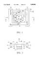
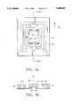
- FIG. 1is a top plan view of a micromachined device in accord with the present invention.
- FIG. 2is a sectional view taken along lines 2--2 in FIG. 1.
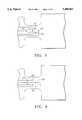
- FIG. 3is an enlargement of a torsional hinge of the device of FIG. 1, showing a torsion transducer.
- FIG. 4illustrates an alternate embodiment of the torsion transducer shown in FIG. 3.
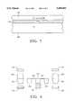
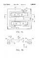
- FIG. 5is a partial cutaway plan view of a Simox wafer for fabricating devices of the present invention.
- FIG. 6is a side view of a plan for fabricating symmetric devices with the present invention by means of wafer bonding.
- FIGS. 7a and 7billustrate magnetic drive structures for the device of the present invention.
- FIGS. 8a and 8billustrate an alternate drive configuration with driven and sensing axes inverted.
- FIGS. 9a and 9billustrate torsion accelerometer devices in accordance with the present invention.
- an outer silicon frame 101oscillates around a pair of hinges (y-axis) 103, and is attached to an inner frame 105, which itself is attached to a fixed inner post 109 with a set of torsion hinges 107 (along the x-axis), at right angles to the first set of hinges.
- the outer frameis made to be self-oscillating, in a well controlled amplitude, and is driven by either electrostatic or magnetic forces e.g. using plates 113 which communicate electrostatic or magnetic force to the spaced apart outer frame.
- One or more built-in torsion sensor 111 in the silicon outer hingesprovides the means for self-oscillation and amplitude stabilization.
- Rotation of the system around the z axiscauses the moving mass of the outer frame 101 and the inner frame 105 to oscillate at the outer frequency around the inner hinges 107 due to Coriolis forces, thereby periodically torsioning these hinges.
- the amplitude of the oscillation around the inner hingesis proportional to the rate of the imposed z axis rotation.
- These inner hingesare also equipped with a similar four-terminal piezo torsion sensor or a capacitive sensor 115, which measures the deformation of the hinges, which is proportional to the rate of rotation of the structure. Leads for the various sensors are brought in from the fixed binding post 117; if necessary the transducer can be inverted 180 degrees and bonded directly to leads on the post.
- the designallows for very good sensitivity, due to the large amplitude of the outer oscillator, its large moment of inertia for a given chip size, outstanding Si spring characteristics, and excellent sensitivity of the torsional sensor. As it turns out many of the desired orientations for anisotropic Si etching coincide with those for optimal torsion sensing. Because of the complete integration of all these parts in silicon, the device can be made very inexpensively. If necessary, the electronic drive circuits could also be integrated.
- the torsional resonance around the inner hingeis chosen higher than the resonance of the outer hinge. It is possible to put the resonance frequency around the x-axis close to the resonance frequency of the outer frame around the y-axis hinges. Hence if so desired, the excursion obtained around the inner springs can be much larger than the "static" signal which would be obtained if no resonance took place. This is the feature which is used in the previous embodiments (except for the inversion of inner and outer axes); however it requires exact setting of the inner resonance frequency.
- the inner resonance frequencychanges as the outer frame rotates around the y axis, since this causes the moment of inertia along the x axis to change. Cross coupling will take place; to avoid this, it is better to separate the resonance frequencies if the increased sensitivity is not needed.
- ⁇is the angle of the gyro (inner axis), j the moment of inertia of the gyro, b the damping constant (if any is present) and k the spring constant of the inner hinges.
- ⁇is the rate of rotation around the z axis
- his the spin momentum, given by the product of I ⁇ where I is the moment of inertia and ⁇ the angular frequency of the oscillating body.
- a typical designmay have an outer square frame 101 dimension of 5 mm, a wafer thickness of 500 microns, 800 micron widths for frames 101 and 105, outer hinges 103 being 200 microns long, 80 microns wide, 10 microns thick, inner hinges 107 of equal thickness, 175 microns long and 100 microns wide, and a square inner post 1.4 mm on a side.
- This designgives a resonance frequency of about 133 Hz around the outer hinges, and 150 Hz around the inner hinges.
- the calculated figure of meritis 0.001 which means that a rotation rate of 1 rad/sec gives a deflection angle of 0.06 degrees, which is quite a large angle. A small fraction of this angle can be readily detected by the torsion sensor.
- the preferred torsion sensor (111, 115)is of the four terminal type as illustrated in FIG. 3 and similar to the type described by Pfann et al., but optimized here for a hinge. See “Semiconducting Stress Transducers utilizing the Transverse and Shear Piezo Resistance Effects", W. G. Pfann and R. N. Thurston, Journ. Appl. Phys., Vol. 32, 10, pg. 2008, 1961. Current is passed through terminals 121 and 123 perpendicular to the flexure hinge length, and the output voltage is measured between terminals 125 and 127.
- Torsion of the hingegives rise to a change in the voltage between points 125 and 127.
- stresses presentare pure shear stresses, oriented parallel to the indicated current direction.
- the field generated in the perpendicular directionis given by the expression:
- Eis the field
- ⁇the nominal resistivity of the material
- ithe current density
- ⁇the shear stress
- ⁇the relevant element of the piezoresistive tensor in the particular direction.
- the current sectioncan be made as long as is desirable, and the generated voltage, which is the integral of the field, should increase linearly with the length of the current section.
- the generated voltagecould exceed the applied voltage at the current terminal, but in practice because of shorting due to the current electrodes, the generated voltage never gets that high.
- the geometry of the sensormatches perfectly the geometry of the hinge.
- FIG. 4Another orientation is illustrated in FIG. 4.
- the currentis parallel to the hinge length from 131 to 133, and the voltage is picked up perpendicular to the hinge length between terminals 135 and 137.
- the field generatedis given by the same expression, but the current width is now restricted to the width of the hinge.
- the only way to increase the voltage here,is to increase the applied voltage at the current leads.
- the first orientation of the torsion sensoris also advantageous for another reason: the current supply lines are usually quite broad, and they leave little room to bring out the voltage sensing lines, if they are oriented as in FIG. 4. If the hinge is under considerable shear stress, then it is advantageous to put the current carrying lines at the edge of the hinge, where the shear stress is zero, as this reduces metal fatigue.
- Siliconin the right orientation, is extremely sensitive to shear, more so than to any other stress.
- the highest shear sensitivitiesare obtained with the torsion bar in the (100) direction for p type silicon, and in the (110) direction for n type silicon.
- the piezo-resistance coefficientsare almost independent of doping, until the resistivity reaches a value on the order of 0.01 ohm-cm. Note that the output of this torsion sensor is independent of any linear stresses or bending of the hinge. Instead of 4 contact points, (2 for current, 2 for voltage), the number can be reduced to 3, using one current injection and two symmetrically placed current pickup points.
- the described piezo voltageis a bulk effect; however in many hinges of interest, the thickness of the hinge is much less than the width of the hinge. Since the shear stress reverses sign on the other face of the hinge, the generated voltages also reverse sign. The effects would then tend to cancel each other if the current were uniform throughout the thickness of the hinge. Therefore the applied current must be restricted to one half of the hinge, where the shear stress has always the same sign. In practice it is best to restrict the current to the top few microns of the hinge, as the stress is largest there, and to reduce the power dissipation.
- junction isolatione.g., making an n type well in a p type substrate.
- the applied current to the torsion sensorcan be AC, usually at a frequency higher than any of the resonant frequencies.
- the torsionthen produces an amplitude modulation of the pickup voltage at the driving frequency, which can be readily demodulated, giving the desired signal.
- the output of the torsion sensorcan be used in a positive feedback scheme to resonate the oscillator at its resonant frequency, or used as a measure of the deflection of the hinge, or both.
- Simox wafersare preferred, although in principle any other silicon on insulator wafer, with a similar structure can be used.
- Epitaxially grown silicon, of a different type as its underlying substratecan also be used together with electrolytic etching. What is required is a layer of high quality, stress free silicon separated from the bulk by a suitable etch stop. When the hinges are made out of this Simox material, they are virtually stress free, and of very high quality.
- Simox wafers of the type shown in FIG. 5consist of an epitaxial single crystal silicon layer 141, from a fraction of a micron to tens of microns thick, grown on top of an oxide layer 143.
- top Si layer 141Underneath the top Si layer 141 is a silicon dioxide layer 143, typically several thousands of Angstroms thick, and which itself sits on top of the bulk of the silicon wafer 145.
- silicon dioxide layer 143typically several thousands of Angstroms thick, and which itself sits on top of the bulk of the silicon wafer 145.
- Other silicon on insulator structurescan be used, equivalent in topography to Simox, but using different methods to produce the structure.
- the oxideprovides for a very good, well controlled and clean etch stop. Since the epi deposition gives rise to a uniform thickness layer, the thickness of the hinges, determined by the thickness of the epi, are very uniform in size all over the wafer. This property gives rise to a very uniform hinge thickness, which is critical to obtain a uniform resonance frequency of all the devices on the wafer.
- the waferis etched from the back, defining the various cavities and masses, as is well known in the art, using the appropriate anisotropic etchant.
- frames 101, 105 and post 109are etched from the silicon wafer.
- Edge compensationcan be used to protect the convex corners of the frames, if any are present.
- Etching of the cornersis not critical, provided that all corners are etched symmetrically to preserve the symmetry of the mass.
- the epitaxial siliconis etched from the front, which defines the hinges and the outline of the plate. This can be done with an RIE chlorine etch or again using an anisotropic etch.
- Hinges 107 in FIGS. 1 and 2are an example.
- the oscillating framecan be either the full thickness of the starting wafer, or alternatively, the thickness of the epi layer.
- the etching procedure stepsmay be reversed if so desired. No mass needs to be plated here; it is provided by the silicon itself, and can be very substantial.
- Ohmic contacts for the torsion sensor on the hingecan be lithographically defined, deposited and annealed in place as is well known in the state of the art using for example gold.
- the goldreadily withstands the etchants used.
- the contacts for the sensorare made before any deep lithography steps are done, since otherwise the patterning becomes very difficult.
- the device illustratedsuffers from some cross-pendulosity. That is, the center of mass of the oscillator, and its rotation axis do not coincide.
- the centrifugal forces createdproduce an excitation at double the frequency of oscillation and may excite the vertical shaking mode of the oscillator. For that reason the mode spectrum of the oscillator should be as clean as possible.
- the torsional resonance modeshould be the lowest in the mode spectrum, and separated as much as possible from any of the higher modes by at least 20% of the lower resonance frequency. Generally this is easier to do if the resonance frequency is low.
- FIG. 6one processed Simox wafer 101 and a regular wafer 147 are bonded together, with their crystal orientations aligned.
- the Simox waferis processed in the usual way, first forming the hinge pattern in the epitaxial layer and the joined lower frame portions in the main wafer body, i.e. those portions of the frame which are on the same plane as the hinges and below. The wafer is then etched to remove excess material. The second wafer is then bonded to the Simox wafer. A pattern corresponding to the upper portion of the frame, i.e. above the plane of the hinges, is masked and excess wafer material is etched away.
- Two Simox waferscould be used, but this is not necessary. This can be done in a variety of ways as is known in the state of the art. By choosing wafers of the same thickness, an essentially symmetric structure can be obtained.
- the entire structurecan be mounted in a vacuum enclosure.
- the inner walls of the enclosurecan be used to support the driving electrodes which are spaced from frame members.
- the torsion oscillatorbe self-starting and self-oscillating, that is selecting its own natural resonance frequency rather than having an externally imposed frequency. This is accomplished by using a torsion sensor 111 of the above type in one of the y axis hinges 103. Its output, demodulated if necessary, is then sufficiently amplified and fed back with the right phase to the driving mechanism, either electrostatic or electromagnetic, to create enough positive feedback to sustain oscillation at a controlled amplitude. Alternatively, the resonance condition of the outer oscillator can be sensed by observing the linear strains in the inner torsion hinges.
- the rotation of the outer frameproduces by reaction a periodic flexing of the inner hinges, which generates compressive and tensile stresses in them. These can be picked up by common two terminal piezoresistive elements.
- n type materialis not very sensitive to longitudinal stresses, although usable, while p type is.
- the best material for such dual useis p type material, oriented in the 110 direction.
- An n-type well in this materialwill provide optimum sensing of torsion, while the p type material is optimum for tensile stresses.
- the stress sensingis usually restricted to the top few micron.
- the torsion sensorsare not sensitive to compressive and tensile stresses.
- the excitation of the outer oscillatorshould be done as symmetrically as possible, with a pull-pull arrangement 113 if done electrostatically as illustrated in FIG. 1.
- magnetic excitationcan also be used. This is schematically illustrated in FIGS. 7a and 7b.
- a coil 151is deposited on the outer frame 101, but isolated by a thin layer of dielectric to avoid shorting, and current is passed through leads 153.
- Small permanent magnets 155 and a magnetic keeper 157provide a magnetic structure, creating a B field 159.
- the interaction between the current and the fieldcauses forces 161 on the coil 151, giving rise to a torque 163, around the hinges 103. Because the structure is rather small, relatively large magnetic fields can be produced with inexpensive magnets.
- the coil 151is plated on the outer frame and returns through one hinge.
- This drive methodrequires no high voltages as is needed for the electrostatic drive, which not only makes the drive, but the pick-up of the small torsion signals more easy.
- the magnetic fields 159should be symmetric, including the fringing fields in the x direction. If not, the current interaction with this transverse field will produce torque around the x-axis.
- the electrostatic voltages needed for drivingcan be greatly reduced, if the gyro is operated in vacuum. Because the Q has been observed to be close to 1 million, the driving voltages can be readily reduced to about a volt. Because the driving forces are then negligible, as compared to the inertia of the rotating mass, symmetry of the drive becomes unimportant. The mode spectrum also tends to be purer in vacuum. Inexpensive vacuum enclosures can be made through micromachining and wafer bonding techniques.
- the detection scheme on the inner axiscan be operated two ways: either as a straight sensor or as a force feedback scheme.
- the latteris well known to be in principle preferable as it reduces the cross coupling, but requires more complex electronics.
- Force feedbackcan be accomplished using either magnetic or electrostatic forces. The first one may be desirable, but can only be used if electrostatic forces are used for the driving, because crossed magnetic fields cause interaction.
- the preferred modehas been described as one where the inner mass 109 is fixed, and the outer frame 101 moving.
- Driving the inner axis 175(either electrically with plates or magnetically), using the torsion sensor 181 allows the mass 171 to be driven at its own resonance frequency, with a well controlled amplitude. This is less efficient in terms of the factor of merit than the first mode, but it makes the lead contact problem somewhat easier.
- Resonance frequencies around both axescan be selected to be coincident, to increase the sensitivity of the system, but subject to the above mentioned limitations.
- both the configuration of U.S. Pat. Nos. 4,598,858 and 5,016,092can be executed using the Simox silicon hinge and mass material and the described torsion sensors instead of the capacitive pickups.
- the substantive massis put at the inner x-axis gimbal, and is driven, magnetically or electrostatically, around the outer axis, nominally at the resonance frequency of the inner axis. Excitation of the inner axis resonance occurs when the sensor rotates around the z axis.
- the x-axisis normally not excited, and therefore cannot be used for setting the frequency of the y drive. Dead reckoning must be used. Any drift between the driving frequency and the resonance frequency causes an apparent loss of sensitivity.
- hingesbe made out of the single crystal material as described, and that the sensor be of the four-terminal piezo voltage type as described.
- a preferred embodimentis illustrated in FIG. 9, using a current loop as the actuator and sensor 193 for the feed-back system.
- B field 199is created by an external structure as above; interaction with current loop 191 causes forces 201, producing torque around hinge 197, which itself connects plate 203, carrying eccentric mass 195, to frame 205.
- the unbalanced mass 195is created here by etching.
- the weight, hinge and magnetic fieldare all uncritical; a simple calibration can be done by holding the accelerometer flat and then inverting it; this produces a 2 g acceleration.
- the current which is necessary to keep the unbalanced mass in place, as measured by a zero output signal from the torsion sensor 193,is a measure of the acceleration which the sensor is subjected to.
- the signal from the accelerometeris in principle derived from an acceleration in the z axis, but acceleration in the x-axis also gives a small, undesirable output signal, as the center of mass is not in the plane of the hinges.
- the same current sourcecan in principle be used to drive both sensors, but the voltages of the sensor outputs can only be added after removal of the common mode signal.
- the mass unbalancecan be created by making one arm longer than the other, or by removing the mass completely from one arm.
- the lattermay be more advantageous, as it is lighter, and produces less stress on the hinges when high g forces arise.
- the output signalis the current needed to keep the hinge 113 undeflected, and is linearly related to the z axis acceleration.
- a substantial symmetric masscan also be obtained by wafer bonding, as defined above.
- the devicecan also be made by using an electrostatic field to keep the plate in place, as is common for most feedback accelerometers.
- the plateneeds to be very close, which makes the design difficult.
- the magnetic approachdoes not suffer from this difficulty; also the homogeneity of the magnetic field is of no concern, since the hinge never tilts, as restricted by the servo loop.
- a single current loop, one turn coil 191is adequate to provide the necessary restoring force, so that no overlap of the coil winding is necessary.
- Force (or torque) feedback accelerometershave generally superior performance as compared to other devices, especially for low frequencies, but their cost is generally quite high.
- the proposed systemis a low cost version, which preserves most of the performance characteristics, while drastically lowering cost.
- the resonance frequencyis on the order of 180 Hz, and with a 1000 Gauss external magnetic field, the current for 0.1 g acceleration is 10 mA, for a single turn loop, a readily measured value.
- the torsion sensor 193is again of the four-terminal piezo voltage type; its output is now maintained at zero by the feedback loop.
Landscapes
- Physics & Mathematics (AREA)
- General Physics & Mathematics (AREA)
- Optics & Photonics (AREA)
- Electromagnetism (AREA)
- Engineering & Computer Science (AREA)
- Radar, Positioning & Navigation (AREA)
- Remote Sensing (AREA)
- Gyroscopes (AREA)
- Micromachines (AREA)
Abstract
Description
jφ+bφ+kφ=-hψ
E=iρσπ
Claims (10)
Priority Applications (9)
| Application Number | Priority Date | Filing Date | Title |
|---|---|---|---|
| US08/208,424US5488862A (en) | 1993-10-18 | 1994-03-08 | Monolithic silicon rate-gyro with integrated sensors |
| JP52360195AJP3483567B2 (en) | 1994-03-08 | 1995-03-07 | Monolithic silicon rate gyro with integrated sensor |
| PCT/US1995/002854WO1995024652A1 (en) | 1994-03-08 | 1995-03-07 | Monolithic silicon rate-gyro with integrated sensors |
| DE69527714TDE69527714T2 (en) | 1994-03-08 | 1995-03-07 | MONOLITHIC SILICON ROTATING SPEED SENSOR WITH INTEGRATED SENSORS |
| EP95913591AEP0767915B1 (en) | 1994-03-08 | 1995-03-07 | Monolithic silicon rate-gyro with integrated sensors |
| US08/595,042US5648618A (en) | 1993-10-18 | 1996-01-31 | Micromachined hinge having an integral torsion sensor |
| US08/855,883US6044705A (en) | 1993-10-18 | 1997-05-12 | Micromachined members coupled for relative rotation by torsion bars |
| US09/428,946US6426013B1 (en) | 1993-10-18 | 1999-10-28 | Method for fabricating micromachined members coupled for relative rotation |
| US09/518,364US6467345B1 (en) | 1993-10-18 | 2000-03-03 | Method of operating micromachined members coupled for relative rotation |
Applications Claiming Priority (2)
| Application Number | Priority Date | Filing Date | Title |
|---|---|---|---|
| US08/139,397US5629790A (en) | 1993-10-18 | 1993-10-18 | Micromachined torsional scanner |
| US08/208,424US5488862A (en) | 1993-10-18 | 1994-03-08 | Monolithic silicon rate-gyro with integrated sensors |
Related Parent Applications (1)
| Application Number | Title | Priority Date | Filing Date |
|---|---|---|---|
| US08/139,397Continuation-In-PartUS5629790A (en) | 1993-10-18 | 1993-10-18 | Micromachined torsional scanner |
Related Child Applications (2)
| Application Number | Title | Priority Date | Filing Date |
|---|---|---|---|
| US08/595,042DivisionUS5648618A (en) | 1993-10-18 | 1996-01-31 | Micromachined hinge having an integral torsion sensor |
| US08/595,042ContinuationUS5648618A (en) | 1993-10-18 | 1996-01-31 | Micromachined hinge having an integral torsion sensor |
Publications (1)
| Publication Number | Publication Date |
|---|---|
| US5488862Atrue US5488862A (en) | 1996-02-06 |
Family
ID=22774558
Family Applications (2)
| Application Number | Title | Priority Date | Filing Date |
|---|---|---|---|
| US08/208,424Expired - Fee RelatedUS5488862A (en) | 1993-10-18 | 1994-03-08 | Monolithic silicon rate-gyro with integrated sensors |
| US08/595,042Expired - LifetimeUS5648618A (en) | 1993-10-18 | 1996-01-31 | Micromachined hinge having an integral torsion sensor |
Family Applications After (1)
| Application Number | Title | Priority Date | Filing Date |
|---|---|---|---|
| US08/595,042Expired - LifetimeUS5648618A (en) | 1993-10-18 | 1996-01-31 | Micromachined hinge having an integral torsion sensor |
Country Status (5)
| Country | Link |
|---|---|
| US (2) | US5488862A (en) |
| EP (1) | EP0767915B1 (en) |
| JP (1) | JP3483567B2 (en) |
| DE (1) | DE69527714T2 (en) |
| WO (1) | WO1995024652A1 (en) |
Cited By (150)
| Publication number | Priority date | Publication date | Assignee | Title |
|---|---|---|---|---|
| US5604309A (en)* | 1994-03-28 | 1997-02-18 | The Charles Stark Draper Laboratory, Inc. | Electronics for Coriolis force and other sensors |
| WO1997021977A1 (en)* | 1995-12-11 | 1997-06-19 | Adagio Associates, Inc. | Integrated silicon profilometer and afm head |
| WO1997023800A1 (en)* | 1995-12-26 | 1997-07-03 | Xros, Inc. | Compact document scanner or printer engine |
| WO1997024578A1 (en)* | 1995-12-27 | 1997-07-10 | Tovarischestvo S Ogranichennoi Otvetstvennostju Nauchno-Proizvodstvennaya Kompania 'vektor' | Micromechanical vibration gyroscope |
| WO1997026527A1 (en)* | 1996-01-22 | 1997-07-24 | Xros, Inc. | Vane-type micromachined silicon micro-flow meter |
| US5861549A (en)* | 1996-12-10 | 1999-01-19 | Xros, Inc. | Integrated Silicon profilometer and AFM head |
| DE19745083A1 (en)* | 1997-10-11 | 1999-04-15 | Bodenseewerk Geraetetech | Rotation rate sensor using Coriolis effect |
| US5914801A (en)* | 1996-09-27 | 1999-06-22 | Mcnc | Microelectromechanical devices including rotating plates and related methods |
| US5948972A (en)* | 1994-12-22 | 1999-09-07 | Kla-Tencor Corporation | Dual stage instrument for scanning a specimen |
| EP0950227A4 (en)* | 1996-05-01 | 1999-10-20 | ||
| US5982528A (en)* | 1998-01-20 | 1999-11-09 | University Of Washington | Optical scanner having piezoelectric drive |
| US6007208A (en)* | 1995-12-19 | 1999-12-28 | The Board Of Trustees Of The Leland Stanford Junior University | Miniature scanning confocal microscope |
| US6009751A (en)* | 1998-10-27 | 2000-01-04 | Ljung; Bo Hans Gunnar | Coriolis gyro sensor |
| US6049407A (en)* | 1997-05-05 | 2000-04-11 | University Of Washington | Piezoelectric scanner |
| US6064779A (en)* | 1997-07-23 | 2000-05-16 | Xros, Inc. | Handheld document scanner |
| US6128953A (en)* | 1992-10-13 | 2000-10-10 | Nippondenso Co., Ltd | Dynamical quantity sensor |
| US6192756B1 (en)* | 1998-02-12 | 2001-02-27 | Ngk Insulators, Ltd. | Vibrators vibratory gyroscopes a method of detecting a turning angular rate and a linear accelerometer |
| US6214243B1 (en)* | 1995-10-20 | 2001-04-10 | Robert Bosch Gmbh | Process for producing a speed of rotation coriolis sensor |
| US6229139B1 (en) | 1998-07-23 | 2001-05-08 | Xros, Inc. | Handheld document scanner |
| US6232790B1 (en) | 1999-03-08 | 2001-05-15 | Honeywell Inc. | Method and apparatus for amplifying electrical test signals from a micromechanical device |
| US6245590B1 (en)* | 1999-08-05 | 2001-06-12 | Microvision Inc. | Frequency tunable resonant scanner and method of making |
| US6256131B1 (en) | 1999-08-05 | 2001-07-03 | Microvision Inc. | Active tuning of a torsional resonant structure |
| US6275320B1 (en) | 1999-09-27 | 2001-08-14 | Jds Uniphase, Inc. | MEMS variable optical attenuator |
| US6285489B1 (en) | 1999-08-05 | 2001-09-04 | Microvision Inc. | Frequency tunable resonant scanner with auxiliary arms |
| US6331909B1 (en) | 1999-08-05 | 2001-12-18 | Microvision, Inc. | Frequency tunable resonant scanner |
| US6362912B1 (en) | 1999-08-05 | 2002-03-26 | Microvision, Inc. | Scanned imaging apparatus with switched feeds |
| WO2002024570A1 (en)* | 2000-09-25 | 2002-03-28 | Bookham Technology Plc | Micro electro-mechanical systems |
| US6384406B1 (en) | 1999-08-05 | 2002-05-07 | Microvision, Inc. | Active tuning of a torsional resonant structure |
| US6392220B1 (en) | 1998-09-02 | 2002-05-21 | Xros, Inc. | Micromachined members coupled for relative rotation by hinges |
| WO2002044652A1 (en)* | 2000-12-02 | 2002-06-06 | Eads Deutschland Gmbh | Micromechanical inertial sensor |
| US6407844B1 (en) | 2001-02-09 | 2002-06-18 | Nayna Networks, Inc. | Device for fabricating improved mirror arrays for physical separation |
| US6433907B1 (en) | 1999-08-05 | 2002-08-13 | Microvision, Inc. | Scanned display with plurality of scanning assemblies |
| US6445844B1 (en) | 1999-09-15 | 2002-09-03 | Xros, Inc. | Flexible, modular, compact fiber optic switch |
| US6445362B1 (en) | 1999-08-05 | 2002-09-03 | Microvision, Inc. | Scanned display with variation compensation |
| US6449098B1 (en) | 2000-05-16 | 2002-09-10 | Calient Networks, Inc. | High uniformity lens arrays having lens correction and methods for fabricating the same |
| US6456751B1 (en) | 2000-04-13 | 2002-09-24 | Calient Networks, Inc. | Feedback stabilization of a loss optimized switch |
| US6477291B1 (en) | 2001-09-13 | 2002-11-05 | Nayna Networks, Inc. | Method and system for in-band connectivity for optical switching applications |
| US6474162B1 (en) | 1995-08-08 | 2002-11-05 | Eads Deutschland Gmbh | Micromechanical rate of rotation sensor (DRS) |
| US6483961B1 (en) | 2000-06-02 | 2002-11-19 | Calient Networks, Inc. | Dual refraction index collimator for an optical switch |
| US6494094B1 (en)* | 1999-11-01 | 2002-12-17 | Mitsubishi Denki Kabushiki Kaisha | Angular rate sensor |
| US6515781B2 (en) | 1999-08-05 | 2003-02-04 | Microvision, Inc. | Scanned imaging apparatus with switched feeds |
| US6520005B2 (en) | 1994-12-22 | 2003-02-18 | Kla-Tencor Corporation | System for sensing a sample |
| US6525864B1 (en) | 2000-07-20 | 2003-02-25 | Nayna Networks, Inc. | Integrated mirror array and circuit device |
| US6525310B2 (en) | 1999-08-05 | 2003-02-25 | Microvision, Inc. | Frequency tunable resonant scanner |
| US6529654B1 (en) | 2001-05-02 | 2003-03-04 | Nayna Networks, Inc. | Method for transparent switching and controlling optical signals using mirror designs |
| US6527965B1 (en) | 2001-02-09 | 2003-03-04 | Nayna Networks, Inc. | Method for fabricating improved mirror arrays for physical separation |
| US20030058190A1 (en)* | 2001-09-21 | 2003-03-27 | Microvision, Inc. | Scanned display with pinch, timing, and distortion correction |
| US6544863B1 (en) | 2001-08-21 | 2003-04-08 | Calient Networks, Inc. | Method of fabricating semiconductor wafers having multiple height subsurface layers |
| US6560384B1 (en) | 2000-06-01 | 2003-05-06 | Calient Networks, Inc. | Optical switch having mirrors arranged to accommodate freedom of movement |
| US6563106B1 (en) | 2000-02-01 | 2003-05-13 | Calient Networks, Inc. | Micro-electro-mechanical-system (MEMS) mirror device and methods for fabricating the same |
| US6577427B1 (en)* | 2001-02-20 | 2003-06-10 | Nayna Networks, Inc. | Process for manufacturing mirror devices using semiconductor technology |
| US6578974B2 (en) | 2000-05-18 | 2003-06-17 | Calient Networks, Inc. | Micromachined apparatus for improved reflection of light |
| US6597826B1 (en) | 1999-11-02 | 2003-07-22 | Xros, Inc. | Optical cross-connect switching system with bridging, test access and redundancy |
| US6597825B1 (en) | 2001-10-30 | 2003-07-22 | Calient Networks, Inc. | Optical tap for an optical switch |
| US6608297B2 (en) | 1997-07-23 | 2003-08-19 | Xeros, Inc. | Scanner document speed encoder |
| WO2003071331A1 (en)* | 2002-02-19 | 2003-08-28 | Glimmerglass Networks, Inc. | Folded longitudinal torsional hinge for gimbaled mems mirror hinge |
| US6614517B1 (en) | 2001-09-18 | 2003-09-02 | Nayna Networks, Inc. | Method and computer aided apparatus for aligning large density fiber arrays |
| US6626039B1 (en) | 1999-09-17 | 2003-09-30 | Millisensor Systems And Actuators, Inc. | Electrically decoupled silicon gyroscope |
| US6628041B2 (en) | 2000-05-16 | 2003-09-30 | Calient Networks, Inc. | Micro-electro-mechanical-system (MEMS) mirror device having large angle out of plane motion using shaped combed finger actuators and method for fabricating the same |
| US6641273B1 (en)* | 2002-06-28 | 2003-11-04 | Glimmerglass Networks, Inc. | MEMS structure with mechanical overdeflection limiter |
| US6643425B1 (en) | 2000-08-17 | 2003-11-04 | Calient Networks, Inc. | Optical switch having switch mirror arrays controlled by scanning beams |
| US6650803B1 (en) | 1999-11-02 | 2003-11-18 | Xros, Inc. | Method and apparatus for optical to electrical to optical conversion in an optical cross-connect switch |
| US6654158B2 (en) | 2001-04-20 | 2003-11-25 | Microvision, Inc. | Frequency tunable resonant scanner with auxiliary arms |
| US6653621B2 (en) | 2001-03-23 | 2003-11-25 | Microvision, Inc. | Frequency tunable resonant scanner and method of making |
| US6661393B2 (en) | 1999-08-05 | 2003-12-09 | Microvision, Inc. | Scanned display with variation compensation |
| US6668108B1 (en) | 2000-06-02 | 2003-12-23 | Calient Networks, Inc. | Optical cross-connect switch with integrated optical signal tap |
| US6694072B1 (en) | 1999-07-21 | 2004-02-17 | Armand P. Neukermans | Flexible, modular, compact fiber switch improvements |
| US20040046484A1 (en)* | 2002-09-04 | 2004-03-11 | Schiller Peter J. | Interface electronics for piezoelectric devices |
| US6715352B2 (en) | 2001-06-26 | 2004-04-06 | Microsensors, Inc. | Method of designing a flexure system for tuning the modal response of a decoupled micromachined gyroscope and a gyroscoped designed according to the method |
| US6718823B2 (en) | 2002-04-30 | 2004-04-13 | Honeywell International Inc. | Pulse width modulation drive signal for a MEMS gyroscope |
| US20040085617A1 (en)* | 2002-11-01 | 2004-05-06 | Microvision, Inc. | Frequency tunable resonant scanner with auxiliary arms |
| US20040083812A1 (en)* | 2002-11-04 | 2004-05-06 | Toshihiko Ichinose | Z-axis vibration gyroscope |
| US6749346B1 (en) | 1995-11-07 | 2004-06-15 | The Board Of Trustees Of The Leland Stanford Junior University | Miniature scanning confocal microscope |
| US6753638B2 (en) | 2000-02-03 | 2004-06-22 | Calient Networks, Inc. | Electrostatic actuator for micromechanical systems |
| US20040119004A1 (en)* | 2002-11-25 | 2004-06-24 | Microvision, Inc. | Frequency tunable resonant scanner and method of making |
| US6771851B1 (en) | 2001-06-19 | 2004-08-03 | Nayna Networks | Fast switching method for a micro-mirror device for optical switching applications |
| US20040150869A1 (en)* | 2002-02-19 | 2004-08-05 | Hiroto Kasai | Mems device and methods for manufacturing thereof, light modulation device, glv device and methods for manufacturing thereof, and laser display |
| US20040159166A1 (en)* | 2003-02-13 | 2004-08-19 | Schiller Peter J. | Solid-state piezoelectric motion transducer |
| US6792177B2 (en) | 2001-03-12 | 2004-09-14 | Calient Networks, Inc. | Optical switch with internal monitoring |
| US6792174B1 (en) | 1999-11-02 | 2004-09-14 | Nortel Networks Limited | Method and apparatus for signaling between an optical cross-connect switch and attached network equipment |
| US6795221B1 (en) | 1999-08-05 | 2004-09-21 | Microvision, Inc. | Scanned display with switched feeds and distortion correction |
| US20040221651A1 (en)* | 2003-05-08 | 2004-11-11 | Schiller Peter J. | Force balanced piezoelectric rate sensor |
| US6825967B1 (en) | 2000-09-29 | 2004-11-30 | Calient Networks, Inc. | Shaped electrodes for micro-electro-mechanical-system (MEMS) devices to improve actuator performance and methods for fabricating the same |
| US6836353B1 (en) | 2001-11-20 | 2004-12-28 | Nayna Networks, Inc. | Redundant switch fabric methods and system for switching of telecommunication signals |
| US6853315B2 (en)* | 2002-01-23 | 2005-02-08 | Triad Sensors, Inc. | Piezoelectric rate sensor system and method |
| RU2246734C1 (en)* | 2003-07-18 | 2005-02-20 | Открытое акционерное общество Арзамасское научно-производственное предприятие "ТЕМП-АВИА" (ОАО АНПП "ТЕМП-АВИА") | Integral accelerometer sensitive element |
| US6882765B1 (en) | 1999-11-02 | 2005-04-19 | Xros, Inc. | Connection protection between clients and optical cross-connect switches |
| US6882766B1 (en) | 2001-06-06 | 2005-04-19 | Calient Networks, Inc. | Optical switch fabric with redundancy |
| US6906849B1 (en)* | 2004-05-14 | 2005-06-14 | Fujitsu Limited | Micro-mirror element |
| US6959583B2 (en) | 2002-04-30 | 2005-11-01 | Honeywell International Inc. | Passive temperature compensation technique for MEMS devices |
| EP1342988A3 (en)* | 2002-03-07 | 2006-08-23 | Alps Electric Co., Ltd. | Capacitive sensor |
| EP1342986A3 (en)* | 2002-03-07 | 2006-08-23 | Alps Electric Co., Ltd. | Capacitive sensor |
| US7098871B1 (en) | 1998-08-05 | 2006-08-29 | Microvision, Inc. | Optical scanning system with correction |
| US20070022827A1 (en)* | 2005-07-28 | 2007-02-01 | Fujitsu Media Devices Limited | Angular velocity sensor |
| US20080062161A1 (en)* | 1999-08-05 | 2008-03-13 | Microvision, Inc. | Apparatuses and methods for utilizing non-ideal light sources |
| US20080106777A1 (en)* | 2006-11-03 | 2008-05-08 | Weir Michael P | Resonant fourier scanning |
| US20080146898A1 (en)* | 2006-12-19 | 2008-06-19 | Ethicon Endo-Surgery, Inc. | Spectral windows for surgical treatment through intervening fluids |
| US20080154248A1 (en)* | 2006-12-22 | 2008-06-26 | Ethicon Endo-Surgery, Inc. | Apparatus and method for medically treating a tattoo |
| US20080151343A1 (en)* | 2006-12-22 | 2008-06-26 | Ethicon Endo-Surgery, Inc. | Apparatus including a scanned beam imager having an optical dome |
| US20080167546A1 (en)* | 2007-01-09 | 2008-07-10 | Ethicon Endo-Surgery, Inc. | Methods for imaging the anatomy with an anatomically secured scanner assembly |
| US20080173803A1 (en)* | 2007-01-18 | 2008-07-24 | Ethicon Endo-Surgery, Inc. | Scanning beam imaging with adjustable detector sensitivity or gain |
| US20080190198A1 (en)* | 2007-02-13 | 2008-08-14 | Stmicroelectronics S.R.L. | Microelectromechanical gyroscope with suppression of capacitive coupling spurious signals and control method |
| US20080226029A1 (en)* | 2007-03-12 | 2008-09-18 | Weir Michael P | Medical device including scanned beam unit for imaging and therapy |
| US20080255458A1 (en)* | 2007-04-13 | 2008-10-16 | Ethicon Endo-Surgery, Inc. | System and method using fluorescence to examine within a patient's anatomy |
| US20090002794A1 (en)* | 2007-06-29 | 2009-01-01 | Ethicon Endo-Surgery, Inc. | Receiver aperture broadening for scanned beam imaging |
| US20090015695A1 (en)* | 2007-07-13 | 2009-01-15 | Ethicon Endo-Surgery, Inc. | Sbi motion artifact removal apparatus and method |
| US20090021818A1 (en)* | 2007-07-20 | 2009-01-22 | Ethicon Endo-Surgery, Inc. | Medical scanning assembly with variable image capture and display |
| US20090036734A1 (en)* | 2007-07-31 | 2009-02-05 | Ethicon Endo-Surgery, Inc. | Devices and methods for introducing a scanning beam unit into the anatomy |
| US20090193893A1 (en)* | 2006-08-09 | 2009-08-06 | Canon Kabushiki Kaisha | Angular velocity sensor |
| US20090245599A1 (en)* | 2008-03-27 | 2009-10-01 | Ethicon Endo-Surgery, Inc. | Method for creating a pixel image from sampled data of a scanned beam imager |
| US20090270724A1 (en)* | 2008-04-25 | 2009-10-29 | Ethicon Endo-Surgery, Inc. | Scanned beam device and method using same which measures the reflectance of patient tissue |
| US20090266164A1 (en)* | 2006-04-28 | 2009-10-29 | Panasonic Electric Works Co., Ltd. | Capacitive sensor |
| RU2379693C1 (en)* | 2008-10-16 | 2010-01-20 | Московский государственный институт электронной техники (технический университет) | Sensitive element of integral accelerometre |
| US20100083756A1 (en)* | 2007-04-05 | 2010-04-08 | Fraunhofer-Gesellschaft zur Foeerderung der angewa | Micromechanical Inertial Sensor for Measuring Rotation Rates |
| US7925333B2 (en) | 2007-08-28 | 2011-04-12 | Ethicon Endo-Surgery, Inc. | Medical device including scanned beam unit with operational control features |
| US7983739B2 (en) | 2007-08-27 | 2011-07-19 | Ethicon Endo-Surgery, Inc. | Position tracking and control for a scanning assembly |
| US7995045B2 (en) | 2007-04-13 | 2011-08-09 | Ethicon Endo-Surgery, Inc. | Combined SBI and conventional image processor |
| WO2011131285A1 (en) | 2010-04-23 | 2011-10-27 | Northrop Grumman Litef Gmbh | Rotational rate sensor arrangement and method for operating a rotational rate sensor arrangement |
| US20110265565A1 (en)* | 2010-04-30 | 2011-11-03 | Qualcomm Mems Technologies, Inc. | Micromachined piezoelectric X-axis gyroscope |
| US8160678B2 (en) | 2007-06-18 | 2012-04-17 | Ethicon Endo-Surgery, Inc. | Methods and devices for repairing damaged or diseased tissue using a scanning beam assembly |
| US8216214B2 (en) | 2007-03-12 | 2012-07-10 | Ethicon Endo-Surgery, Inc. | Power modulation of a scanning beam for imaging, therapy, and/or diagnosis |
| US20120174670A1 (en)* | 2010-07-10 | 2012-07-12 | Omnitek Partners Llc | Inertia Sensors With Multi-Directional Shock Protection |
| US20120200947A1 (en)* | 2011-02-08 | 2012-08-09 | Utah State University Research Foundation | Kinematic Optic Mount |
| US20140076051A1 (en)* | 2012-09-14 | 2014-03-20 | Qing Ma | Accelerometer and method of making same |
| US20140182377A1 (en)* | 2012-12-28 | 2014-07-03 | Kevin L. Lin | Method, apparatus and system for providing metering of acceleration |
| US8801606B2 (en) | 2007-01-09 | 2014-08-12 | Ethicon Endo-Surgery, Inc. | Method of in vivo monitoring using an imaging system including scanned beam imaging unit |
| US20150029606A1 (en)* | 2013-07-26 | 2015-01-29 | GlobalMEMS TAIWAN CORPORATION LIMITED | Micro-electromechanical system (mems) carrier |
| US20150033860A1 (en)* | 2013-07-31 | 2015-02-05 | Samsung Electro-Mechanics Co., Ltd. | Acceleration sensor and angular velocity sensor |
| US20150096374A1 (en)* | 2013-10-04 | 2015-04-09 | Samsung Electro-Mechanics Co., Ltd. | Angular velocity sensor and manufacturing method of the same |
| RU2556334C1 (en)* | 2014-04-03 | 2015-07-10 | Федеральное государственное бюджетное образовательное учреждение высшего профессионального образования "Нижегородский государственный технический университет им. Р.Е. Алексеева", НГТУ | Sensitive element of microsystem gyroscope |
| US9079762B2 (en) | 2006-09-22 | 2015-07-14 | Ethicon Endo-Surgery, Inc. | Micro-electromechanical device |
| US9097897B2 (en) | 2012-09-11 | 2015-08-04 | Stanley Electric Co., Ltd. | Optical deflector including narrow piezoelectric sensor element between torsion bar and piezoelectric actuator |
| US20150277108A1 (en)* | 2014-03-25 | 2015-10-01 | Stanley Electric Co., Ltd. | Optical deflector including meander-type piezoelectric actuators and ill-balanced mirror structure |
| US9195068B2 (en) | 2013-03-25 | 2015-11-24 | Seiko Epson Corporation | Optical scanner manufacturing method, optical scanner, image display device, and head-mounted display |
| CN105137120A (en)* | 2015-09-01 | 2015-12-09 | 中国人民解放军国防科学技术大学 | V-shaped beam pendulous uniaxial micro mechanical acceleration meter and a preparation method thereof |
| US9255782B2 (en) | 2012-08-31 | 2016-02-09 | Stmicroelectronics S.R.L. | MEMS device including a mobile element and a resistive sensor, and method for generating a signal indicating the position of the mobile element |
| EP2573612B1 (en)* | 2005-12-16 | 2016-05-25 | The Charles Stark Draper Laboratory, Inc. | Systems, methods and devices for actuating a movable miniature platform |
| US9446940B2 (en) | 2014-10-03 | 2016-09-20 | Freescale Semiconductor, Inc. | Stress isolation for MEMS device |
| US9458008B1 (en)* | 2015-03-16 | 2016-10-04 | Freescale Semiconductor, Inc. | Method of making a MEMS die having a MEMS device on a suspended structure |
| CN106525304A (en)* | 2016-12-12 | 2017-03-22 | 西安交通大学 | MEMS resonant torque sensor used for linear micro-nano material torsion performance measurement |
| US9815689B2 (en) | 2013-07-26 | 2017-11-14 | GlobalMEMS TAIWAN CORPORATION LIMITED | Micro-electromechanical system (MEMS) carrier |
| US9837526B2 (en) | 2014-12-08 | 2017-12-05 | Nxp Usa, Inc. | Semiconductor device wtih an interconnecting semiconductor electrode between first and second semiconductor electrodes and method of manufacture therefor |
| US20180252744A1 (en)* | 2017-03-03 | 2018-09-06 | Hitachi, Ltd. | Acceleration sensor |
| US10180445B2 (en) | 2016-06-08 | 2019-01-15 | Honeywell International Inc. | Reducing bias in an accelerometer via current adjustment |
| CN109489648A (en)* | 2018-12-30 | 2019-03-19 | 瑞声声学科技(深圳)有限公司 | A kind of gyroscope |
| US10348295B2 (en) | 2015-11-19 | 2019-07-09 | Nxp Usa, Inc. | Packaged unidirectional power transistor and control circuit therefore |
| CN110208784A (en)* | 2019-06-25 | 2019-09-06 | 天津大学 | A kind of splice angle auxiliary measuring method of the unmanned articulated vehicle based on millimetre-wave radar |
| WO2020140171A1 (en)* | 2018-12-30 | 2020-07-09 | 瑞声声学科技(深圳)有限公司 | Gyroscope |
| US11085767B2 (en)* | 2017-07-24 | 2021-08-10 | Senodia Technologies (Shaoxing) Co., Ltd | Three-axis MEMS gyroscope |
| US12103843B2 (en) | 2021-01-20 | 2024-10-01 | Calient.Ai Inc. | MEMS mirror arrays with reduced crosstalk |
Families Citing this family (104)
| Publication number | Priority date | Publication date | Assignee | Title |
|---|---|---|---|---|
| SE9500729L (en)* | 1995-02-27 | 1996-08-28 | Gert Andersson | Apparatus for measuring angular velocity in single crystalline material and method for making such |
| JP3284921B2 (en) | 1997-04-24 | 2002-05-27 | 富士電機株式会社 | Acceleration sensor, angular acceleration sensor and method for manufacturing them |
| US6075639A (en)* | 1997-10-22 | 2000-06-13 | The Board Of Trustees Of The Leland Stanford Junior University | Micromachined scanning torsion mirror and method |
| US20020075210A1 (en)* | 1998-08-05 | 2002-06-20 | Microvision, Inc. | Low light viewer with image simulation |
| US6937221B2 (en)* | 1998-08-05 | 2005-08-30 | Microvision, Inc. | Scanned beam display |
| US6140979A (en)* | 1998-08-05 | 2000-10-31 | Microvision, Inc. | Scanned display with pinch, timing, and distortion correction |
| US6583772B1 (en) | 1998-08-05 | 2003-06-24 | Microvision, Inc. | Linked scanner imaging system and method |
| US6417502B1 (en) | 1998-08-05 | 2002-07-09 | Microvision, Inc. | Millimeter wave scanning imaging system having central reflectors |
| DE19844686A1 (en)* | 1998-09-29 | 2000-04-06 | Fraunhofer Ges Forschung | Micromechanical rotation rate sensor and manufacturing method |
| JP3428458B2 (en)* | 1998-10-01 | 2003-07-22 | 株式会社村田製作所 | Angular velocity sensor |
| US7516896B2 (en)* | 1999-08-05 | 2009-04-14 | Microvision, Inc. | Frequency tunable resonant scanner with auxiliary arms |
| JP2003511684A (en)* | 1999-10-13 | 2003-03-25 | アナログ デバイシーズ インコーポレイテッド | Feedback mechanism for rate gyroscope |
| US6744550B2 (en) | 1999-11-16 | 2004-06-01 | Xros, Inc. | Two-dimensional micro-mirror array enhancements |
| US6343866B1 (en)* | 2000-05-23 | 2002-02-05 | Fujitsu Limited | Optical apparatus which uses a virtually imaged phased array to produce chromatic dispersion |
| KR100373484B1 (en)* | 2000-01-27 | 2003-02-25 | 국방과학연구소 | vibrating micromachined gyroscope |
| EP1342121A2 (en)* | 2000-02-17 | 2003-09-10 | XROS, Inc., Nortel Networks | Two-dimensional micro-mirror array enhancements |
| US6593677B2 (en) | 2000-03-24 | 2003-07-15 | Onix Microsystems, Inc. | Biased rotatable combdrive devices and methods |
| US6330102B1 (en) | 2000-03-24 | 2001-12-11 | Onix Microsystems | Apparatus and method for 2-dimensional steered-beam NxM optical switch using single-axis mirror arrays and relay optics |
| US20010040419A1 (en) | 2000-03-24 | 2001-11-15 | Behrang Behin | Biased rotatable combdrive sensor methods |
| US6788520B1 (en) | 2000-04-10 | 2004-09-07 | Behrang Behin | Capacitive sensing scheme for digital control state detection in optical switches |
| US6610974B1 (en) | 2000-06-05 | 2003-08-26 | Calient Networks, Inc. | Positioning a movable reflector in an optical switch |
| US6728016B1 (en) | 2000-06-05 | 2004-04-27 | Calient Networks, Inc. | Safe procedure for moving mirrors in an optical cross-connect switch |
| US6587611B1 (en) | 2000-06-06 | 2003-07-01 | Calient Networks, Inc. | Maintaining path integrity in an optical switch |
| JP2002023097A (en)* | 2000-07-10 | 2002-01-23 | Olympus Optical Co Ltd | Torsional oscillator |
| US6337760B1 (en) | 2000-07-17 | 2002-01-08 | Reflectivity, Inc. | Encapsulated multi-directional light beam steering device |
| US6441356B1 (en) | 2000-07-28 | 2002-08-27 | Optical Biopsy Technologies | Fiber-coupled, high-speed, angled-dual-axis optical coherence scanning microscopes |
| US6423956B1 (en)* | 2000-07-28 | 2002-07-23 | Optical Biopsy Technologies | Fiber-coupled, high-speed, integrated, angled-dual-axis confocal scanning microscopes employing vertical cross-section scanning |
| GB2384060B (en)* | 2000-08-27 | 2004-12-15 | Corning Intellisense Corp | Magnetically actuated micro-electro-mechanical apparatus |
| US6431714B1 (en)* | 2000-10-10 | 2002-08-13 | Nippon Telegraph And Telephone Corporation | Micro-mirror apparatus and production method therefor |
| ATE437382T1 (en)* | 2000-11-03 | 2009-08-15 | Microvision Inc | FREQUENCY TUNABLE RESONANT RASTER SCANNER WITH AUXILIARY ARMS |
| AU2001213608A1 (en)* | 2000-11-03 | 2002-05-15 | Microvision, Inc. | Scanned display with switched feeds and distortion correction |
| ATE508386T1 (en)* | 2000-11-03 | 2011-05-15 | Microvision Inc | GRID DISPLAY WITH VARIATION COMPENSATION |
| US7193758B2 (en)* | 2001-02-06 | 2007-03-20 | Microvision, Inc. | Scanner and method for sweeping a beam across a target |
| US6480320B2 (en) | 2001-02-07 | 2002-11-12 | Transparent Optical, Inc. | Microelectromechanical mirror and mirror array |
| US7183633B2 (en)* | 2001-03-01 | 2007-02-27 | Analog Devices Inc. | Optical cross-connect system |
| US7180556B2 (en)* | 2001-05-15 | 2007-02-20 | Microvision, Inc. | System and method for capturing, transmitting, and displaying an image |
| US6639719B2 (en) | 2001-05-15 | 2003-10-28 | Microvision, Inc. | System and method for using multiple beams to respectively scan multiple regions of an image |
| US6755536B2 (en)* | 2001-05-15 | 2004-06-29 | Microvision, Inc. | System and method for displaying/projecting a color image |
| US7180555B2 (en)* | 2001-05-15 | 2007-02-20 | Microvision, Inc. | System and method for producing an image with a screen using erase (off) and image (on) light sources |
| US6509620B2 (en)* | 2001-05-31 | 2003-01-21 | Hewlett-Packard Company | Flexure coupling block for motion sensor |
| US7017410B2 (en)* | 2001-08-10 | 2006-03-28 | The Boeing Company | Isolated resonator gyroscope with a drive and sense plate |
| US6629460B2 (en)* | 2001-08-10 | 2003-10-07 | The Boeing Company | Isolated resonator gyroscope |
| US7110633B1 (en) | 2001-08-13 | 2006-09-19 | Calient Networks, Inc. | Method and apparatus to provide alternative paths for optical protection path switch arrays |
| US20030068117A1 (en)* | 2001-08-31 | 2003-04-10 | Syms Richard R.A. | Compact, tolerant large-scale mirror-rotation optical cross-connect switch |
| US6844952B2 (en)* | 2001-09-18 | 2005-01-18 | Vitesse Semiconductor Corporation | Actuator-controlled mirror with Z-stop mechanism |
| JP2003156510A (en)* | 2001-11-22 | 2003-05-30 | Matsushita Electric Works Ltd | Method of manufacturing semiconductor accelerometer |
| US6755982B2 (en)* | 2002-01-07 | 2004-06-29 | Xerox Corporation | Self-aligned micro hinges |
| SE0200787D0 (en)* | 2002-03-15 | 2002-03-15 | Micronic Laser Systems Ab | Improved addressing method |
| US6925710B1 (en) | 2002-03-27 | 2005-08-09 | Analog Devices, Inc. | Method for manufacturing microelectromechanical combdrive device |
| KR100431581B1 (en)* | 2002-05-28 | 2004-05-17 | 한국과학기술원 | Micromirror Actuator |
| GB0212817D0 (en)* | 2002-06-05 | 2002-07-10 | Polatis Ltd | Beam steering arrangements |
| KR100997929B1 (en)* | 2002-08-03 | 2010-12-02 | 시베르타 인코퍼레이티드 | Sealed integral MEMS switch |
| US6843574B2 (en)* | 2002-08-20 | 2005-01-18 | Intel Corporation | Gimbaled micromechanical rotation system |
| US6733144B2 (en) | 2002-09-27 | 2004-05-11 | Intel Corporation | Shock protectors for micro-mechanical systems |
| US6888470B2 (en)* | 2002-09-30 | 2005-05-03 | Lucent Technologies Inc. | Sensing of mirror position in an optical switch |
| US6768571B2 (en)* | 2002-09-30 | 2004-07-27 | Lucent Technologies Inc. | Orientation stabilization for MEMS devices |
| US6911913B2 (en) | 2002-09-30 | 2005-06-28 | Lucent Technologies Inc. | Piezo-resistive sensing of mirror position in an optical switch |
| JP4550578B2 (en)* | 2002-10-10 | 2010-09-22 | 富士通株式会社 | Micro movable element with torsion bar |
| US7071594B1 (en) | 2002-11-04 | 2006-07-04 | Microvision, Inc. | MEMS scanner with dual magnetic and capacitive drive |
| US20040147056A1 (en)* | 2003-01-29 | 2004-07-29 | Mckinnell James C. | Micro-fabricated device and method of making |
| US7982765B2 (en)* | 2003-06-20 | 2011-07-19 | Microvision, Inc. | Apparatus, system, and method for capturing an image with a scanned beam of light |
| US7659918B2 (en)* | 2003-10-08 | 2010-02-09 | Texas Instruments Incorporated | Apparatus and methods for adjusting the rotational frequency of a scanning device |
| JP3759598B2 (en)* | 2003-10-29 | 2006-03-29 | セイコーエプソン株式会社 | Actuator |
| JP4461870B2 (en)* | 2004-03-26 | 2010-05-12 | ブラザー工業株式会社 | Optical scanning device and image forming apparatus having the same |
| JP2007533105A (en)* | 2004-04-12 | 2007-11-15 | シヴァータ・インコーポレーテッド | Single pole double throw MEMS switch |
| JP2005300493A (en)* | 2004-04-16 | 2005-10-27 | Nippon Telegr & Teleph Corp <Ntt> | Semiconductor displacement detector and detector |
| US7407105B2 (en)* | 2004-08-30 | 2008-08-05 | Intermec Ip Corp. | Apparatus for diagonal progressive scanning video and method of improving aiming visibility, reducing tilt dependence and improving read range |
| US20060132153A1 (en)* | 2004-12-22 | 2006-06-22 | Formfactor, Inc. | Assembly with a detachable member |
| JP2006195083A (en)* | 2005-01-12 | 2006-07-27 | Sharp Corp | Optical scanning device |
| KR100644896B1 (en)* | 2005-01-19 | 2006-11-14 | 엘지전자 주식회사 | Electromagnetically driven scanning micromirror and optical scanning device using the same |
| EP1938334A2 (en)* | 2005-08-19 | 2008-07-02 | BEYDER, Arthur | Oscillator and method of making for atomic force microscope and other applications |
| KR100694599B1 (en) | 2006-03-29 | 2007-03-14 | 삼성전자주식회사 | Actuator with Mechanic Filter |
| US7501616B2 (en)* | 2006-05-25 | 2009-03-10 | Microvision, Inc. | Method and apparatus for capturing an image of a moving object |
| US7803244B2 (en)* | 2006-08-31 | 2010-09-28 | Kimberly-Clark Worldwide, Inc. | Nonwoven composite containing an apertured elastic film |
| KR100868758B1 (en)* | 2007-01-15 | 2008-11-13 | 삼성전기주식회사 | Rotating MEMS devices with piezoresistive sensors |
| JP4362739B2 (en)* | 2007-02-26 | 2009-11-11 | 株式会社デンソー | Vibration type angular velocity sensor |
| DE102007033000B4 (en)* | 2007-07-16 | 2016-02-04 | Robert Bosch Gmbh | Micromechanical component with a position detection component for position determination and amplitude determination of a vibratable element |
| US7690272B2 (en)* | 2007-09-28 | 2010-04-06 | Endevco Corporation | Flexural pivot for micro-sensors |
| US7921731B2 (en)* | 2007-12-03 | 2011-04-12 | The United States Of America As Represented By The Administrator Of The National Aeronautics And Space Administration | Two-axis direct fluid shear stress sensor |
| US9016126B2 (en)* | 2009-01-07 | 2015-04-28 | Honeywell International Inc. | MEMS accelerometer having a flux concentrator between parallel magnets |
| WO2010082925A1 (en)* | 2009-01-14 | 2010-07-22 | Hewlett-Packard Development Company, L.P. | Acoustic pressure transducer |
| US20100180681A1 (en)* | 2009-01-22 | 2010-07-22 | Honeywell International Inc. | System and method for increased flux density d'arsonval mems accelerometer |
| JP5421651B2 (en)* | 2009-05-13 | 2014-02-19 | ローム株式会社 | Triaxial angular velocity detection vibrator, triaxial angular velocity detection device, and triaxial angular velocity detection system |
| DE102010029074B4 (en)* | 2010-05-18 | 2018-03-08 | Robert Bosch Gmbh | Connection structure for micro swing devices |
| US8539836B2 (en)* | 2011-01-24 | 2013-09-24 | Freescale Semiconductor, Inc. | MEMS sensor with dual proof masses |
| US9464896B2 (en) | 2012-06-22 | 2016-10-11 | National Institute Of Advanced Industrial Science And Technology | Device for measuring rotation angle acceleration |
| US8754829B2 (en)* | 2012-08-04 | 2014-06-17 | Paul Lapstun | Scanning light field camera and display |
| KR101388814B1 (en)* | 2012-09-11 | 2014-04-23 | 삼성전기주식회사 | Angular Velocity Sensor |
| KR101366990B1 (en)* | 2012-12-28 | 2014-02-24 | 삼성전기주식회사 | Angular velocity sensor |
| US9470709B2 (en) | 2013-01-28 | 2016-10-18 | Analog Devices, Inc. | Teeter totter accelerometer with unbalanced mass |
| US9297825B2 (en) | 2013-03-05 | 2016-03-29 | Analog Devices, Inc. | Tilt mode accelerometer with improved offset and noise performance |
| JP2014182227A (en)* | 2013-03-18 | 2014-09-29 | Seiko Epson Corp | Optical scanner, image display device, and head-mounted display |
| KR101454122B1 (en)* | 2013-07-31 | 2014-10-22 | 삼성전기주식회사 | Sensing Module and Angular Velocity Sensor having the same |
| GB2523320A (en)* | 2014-02-19 | 2015-08-26 | Atlantic Inertial Systems Ltd | Accelerometers |
| DE102014207856A1 (en)* | 2014-04-25 | 2015-10-29 | Robert Bosch Gmbh | Micromechanical sensor arrangement and corresponding manufacturing method |
| JP6459392B2 (en)* | 2014-10-28 | 2019-01-30 | ミツミ電機株式会社 | Optical scanning device |
| US10073113B2 (en) | 2014-12-22 | 2018-09-11 | Analog Devices, Inc. | Silicon-based MEMS devices including wells embedded with high density metal |
| US10078098B2 (en) | 2015-06-23 | 2018-09-18 | Analog Devices, Inc. | Z axis accelerometer design with offset compensation |
| JP6565455B2 (en) | 2015-08-05 | 2019-08-28 | セイコーエプソン株式会社 | Optical scanner, optical scanner manufacturing method, image display device, and head mounted display |
| DE102015117094B4 (en)* | 2015-10-07 | 2020-04-23 | Tdk Electronics Ag | MEMS rotation rate sensor |
| WO2018230065A1 (en)* | 2017-06-13 | 2018-12-20 | 三菱電機株式会社 | Optical scanning device and method for adjusting optical scanning device |
| JP6420442B1 (en)* | 2017-10-16 | 2018-11-07 | 株式会社ワコー | Power generation element |
| JP6496450B1 (en)* | 2018-10-05 | 2019-04-03 | 株式会社ワコー | Power generation element |
| DE102021134310A1 (en) | 2021-12-22 | 2023-06-22 | Tdk Electronics Ag | Piezoelectric mirror component, method for operating the piezoelectric mirror component and projection device with the piezoelectric mirror component |
Citations (5)
| Publication number | Priority date | Publication date | Assignee | Title |
|---|---|---|---|---|
| US4598585A (en)* | 1984-03-19 | 1986-07-08 | The Charles Stark Draper Laboratory, Inc. | Planar inertial sensor |
| US4670092A (en)* | 1986-04-18 | 1987-06-02 | Rockwell International Corporation | Method of fabricating a cantilever beam for a monolithic accelerometer |
| US4699006A (en)* | 1984-03-19 | 1987-10-13 | The Charles Stark Draper Laboratory, Inc. | Vibratory digital integrating accelerometer |
| US5016072A (en)* | 1988-01-13 | 1991-05-14 | The Charles Stark Draper Laboratory, Inc. | Semiconductor chip gyroscopic transducer |
| US5203208A (en)* | 1991-04-29 | 1993-04-20 | The Charles Stark Draper Laboratory | Symmetrical micromechanical gyroscope |
Family Cites Families (11)
| Publication number | Priority date | Publication date | Assignee | Title |
|---|---|---|---|---|
| JPS6341080A (en)* | 1986-08-06 | 1988-02-22 | Nissan Motor Co Ltd | Semiconductor acceleration sensor |
| US5111693A (en)* | 1988-01-13 | 1992-05-12 | The Charles Stark Draper Laboratory, Inc. | Motion restraints for micromechanical devices |
| US5195371A (en)* | 1988-01-13 | 1993-03-23 | The Charles Stark Draper Laboratory, Inc. | Semiconductor chip transducer |
| JPH0413975A (en)* | 1990-05-07 | 1992-01-17 | Nec Corp | Semiconductor acceleration sensor |
| ES2056580T3 (en)* | 1990-05-18 | 1994-10-01 | British Aerospace | INERTIAL SENSORS. |
| US5241861A (en)* | 1991-02-08 | 1993-09-07 | Sundstrand Corporation | Micromachined rate and acceleration sensor |
| CA2116572C (en)* | 1991-08-29 | 1998-06-16 | Lawrence A. Wan | Rotation sensor |
| US5331852A (en)* | 1991-09-11 | 1994-07-26 | The Charles Stark Draper Laboratory, Inc. | Electromagnetic rebalanced micromechanical transducer |
| US5220835A (en)* | 1991-09-12 | 1993-06-22 | Ford Motor Company | Torsion beam accelerometer |
| JPH05333038A (en)* | 1992-06-03 | 1993-12-17 | Canon Inc | Angular velocity sensor |
| GB9212099D0 (en)* | 1992-06-06 | 1992-07-22 | Lucas Ind Plc | Angular rate sensor and method of production thereof |
- 1994
- 1994-03-08USUS08/208,424patent/US5488862A/ennot_activeExpired - Fee Related
- 1995
- 1995-03-07JPJP52360195Apatent/JP3483567B2/ennot_activeExpired - Fee Related
- 1995-03-07EPEP95913591Apatent/EP0767915B1/ennot_activeExpired - Lifetime
- 1995-03-07DEDE69527714Tpatent/DE69527714T2/ennot_activeExpired - Fee Related
- 1995-03-07WOPCT/US1995/002854patent/WO1995024652A1/enactiveIP Right Grant
- 1996
- 1996-01-31USUS08/595,042patent/US5648618A/ennot_activeExpired - Lifetime
Patent Citations (5)
| Publication number | Priority date | Publication date | Assignee | Title |
|---|---|---|---|---|
| US4598585A (en)* | 1984-03-19 | 1986-07-08 | The Charles Stark Draper Laboratory, Inc. | Planar inertial sensor |
| US4699006A (en)* | 1984-03-19 | 1987-10-13 | The Charles Stark Draper Laboratory, Inc. | Vibratory digital integrating accelerometer |
| US4670092A (en)* | 1986-04-18 | 1987-06-02 | Rockwell International Corporation | Method of fabricating a cantilever beam for a monolithic accelerometer |
| US5016072A (en)* | 1988-01-13 | 1991-05-14 | The Charles Stark Draper Laboratory, Inc. | Semiconductor chip gyroscopic transducer |
| US5203208A (en)* | 1991-04-29 | 1993-04-20 | The Charles Stark Draper Laboratory | Symmetrical micromechanical gyroscope |
Non-Patent Citations (6)
| Title |
|---|
| Boxenhorn and Greiff, "Monolithic Silicon Accelerometer", Sensors and Actuators, A21-A23 (1990) 273-277. |
| Boxenhorn and Greiff, Monolithic Silicon Accelerometer , Sensors and Actuators, A21 A23 (1990) 273 277.* |
| Diem, B. et al., "SOI (SIMOX) as a Substrate for Surface Micromachining of Single Crystalline Silicon Sensors and Actuators", The 7th International Conference on Solid-State Sensors and Actuators, pp. 233-236. |
| Diem, B. et al., SOI (SIMOX) as a Substrate for Surface Micromachining of Single Crystalline Silicon Sensors and Actuators , The 7th International Conference on Solid State Sensors and Actuators, pp. 233 236.* |
| Pfann, W. G. et al., "Semiconducting Stress Transducers Utilizing the Transverse and Shear Piezoresistance Effects", Journal of Applied Physics, vol. 32, No. 10, Oct. 1961, pp. 2008-2016. |
| Pfann, W. G. et al., Semiconducting Stress Transducers Utilizing the Transverse and Shear Piezoresistance Effects , Journal of Applied Physics, vol. 32, No. 10, Oct. 1961, pp. 2008 2016.* |
Cited By (258)
| Publication number | Priority date | Publication date | Assignee | Title |
|---|---|---|---|---|
| USRE42359E1 (en) | 1992-10-13 | 2011-05-17 | Denso Corporation | Dynamical quantity sensor |
| US6128953A (en)* | 1992-10-13 | 2000-10-10 | Nippondenso Co., Ltd | Dynamical quantity sensor |
| US6470747B1 (en) | 1992-10-13 | 2002-10-29 | Denso Corporation | Dynamical quantity sensor |
| US5604309A (en)* | 1994-03-28 | 1997-02-18 | The Charles Stark Draper Laboratory, Inc. | Electronics for Coriolis force and other sensors |
| US20050005688A1 (en)* | 1994-12-22 | 2005-01-13 | Amin Samsavar | Dual stage instrument for scanning a specimen |
| US6931917B2 (en) | 1994-12-22 | 2005-08-23 | Kla-Tencor Corporation | System for sensing a sample |
| US7278301B2 (en) | 1994-12-22 | 2007-10-09 | Kla-Tencor Corporation | System for sensing a sample |
| US6520005B2 (en) | 1994-12-22 | 2003-02-18 | Kla-Tencor Corporation | System for sensing a sample |
| US20050262931A1 (en)* | 1994-12-22 | 2005-12-01 | Mcwaid Thomas | System for sensing a sample |
| US20040118193A1 (en)* | 1994-12-22 | 2004-06-24 | Mcwaid Thomas | System for sensing a sample |
| US5948972A (en)* | 1994-12-22 | 1999-09-07 | Kla-Tencor Corporation | Dual stage instrument for scanning a specimen |
| US7100430B2 (en) | 1994-12-22 | 2006-09-05 | Kla-Tencor Corporation | Dual stage instrument for scanning a specimen |
| US6474162B1 (en) | 1995-08-08 | 2002-11-05 | Eads Deutschland Gmbh | Micromechanical rate of rotation sensor (DRS) |
| US6214243B1 (en)* | 1995-10-20 | 2001-04-10 | Robert Bosch Gmbh | Process for producing a speed of rotation coriolis sensor |
| US6749346B1 (en) | 1995-11-07 | 2004-06-15 | The Board Of Trustees Of The Leland Stanford Junior University | Miniature scanning confocal microscope |
| EP0868648A4 (en)* | 1995-12-11 | 2000-03-01 | Xros Inc | Integrated silicon profilometer and afm head |
| US6272907B1 (en) | 1995-12-11 | 2001-08-14 | Xros, Inc. | Integrated silicon profilometer and AFM head |
| WO1997021977A1 (en)* | 1995-12-11 | 1997-06-19 | Adagio Associates, Inc. | Integrated silicon profilometer and afm head |
| US6088145A (en)* | 1995-12-19 | 2000-07-11 | The Board Of Trustees Of The Leland Stanford Junior University | Miniature scanning confocal microscope |
| US6007208A (en)* | 1995-12-19 | 1999-12-28 | The Board Of Trustees Of The Leland Stanford Junior University | Miniature scanning confocal microscope |
| US6154305A (en)* | 1995-12-19 | 2000-11-28 | The Board Of Trustees Of The Leland Stanford Junior University | Miniature scanning confocal microscope |
| WO1997023800A1 (en)* | 1995-12-26 | 1997-07-03 | Xros, Inc. | Compact document scanner or printer engine |
| US5841553A (en)* | 1995-12-26 | 1998-11-24 | Xros, Inc. | Compact document scanner or printer engine |
| WO1997024578A1 (en)* | 1995-12-27 | 1997-07-10 | Tovarischestvo S Ogranichennoi Otvetstvennostju Nauchno-Proizvodstvennaya Kompania 'vektor' | Micromechanical vibration gyroscope |
| EP0912883A4 (en)* | 1996-01-22 | 1999-05-06 | ||
| WO1997026527A1 (en)* | 1996-01-22 | 1997-07-24 | Xros, Inc. | Vane-type micromachined silicon micro-flow meter |
| EP0950227A4 (en)* | 1996-05-01 | 1999-10-20 | ||
| US6555201B1 (en) | 1996-09-27 | 2003-04-29 | Mcnc | Method for fabricating a microelectromechanical bearing |
| US5914801A (en)* | 1996-09-27 | 1999-06-22 | Mcnc | Microelectromechanical devices including rotating plates and related methods |
| US6134042A (en)* | 1996-09-27 | 2000-10-17 | Mcnc | Reflective mems actuator with a laser |
| US6256134B1 (en) | 1996-09-27 | 2001-07-03 | Mcnc | Microelectromechanical devices including rotating plates and related methods |
| US6087747A (en)* | 1996-09-27 | 2000-07-11 | Mcnc | Microelectromechanical beam for allowing a plate to rotate in relation to a frame in a microelectromechanical device |
| US5861549A (en)* | 1996-12-10 | 1999-01-19 | Xros, Inc. | Integrated Silicon profilometer and AFM head |
| US6049407A (en)* | 1997-05-05 | 2000-04-11 | University Of Washington | Piezoelectric scanner |
| US6064779A (en)* | 1997-07-23 | 2000-05-16 | Xros, Inc. | Handheld document scanner |
| US6608297B2 (en) | 1997-07-23 | 2003-08-19 | Xeros, Inc. | Scanner document speed encoder |
| DE19745083A1 (en)* | 1997-10-11 | 1999-04-15 | Bodenseewerk Geraetetech | Rotation rate sensor using Coriolis effect |
| US5982528A (en)* | 1998-01-20 | 1999-11-09 | University Of Washington | Optical scanner having piezoelectric drive |
| US6192756B1 (en)* | 1998-02-12 | 2001-02-27 | Ngk Insulators, Ltd. | Vibrators vibratory gyroscopes a method of detecting a turning angular rate and a linear accelerometer |
| US6229139B1 (en) | 1998-07-23 | 2001-05-08 | Xros, Inc. | Handheld document scanner |
| US7428093B2 (en) | 1998-08-05 | 2008-09-23 | Microvision, Inc. | Optical scanning system with correction |
| US7098871B1 (en) | 1998-08-05 | 2006-08-29 | Microvision, Inc. | Optical scanning system with correction |
| US20080136742A1 (en)* | 1998-08-05 | 2008-06-12 | Microvision, Inc. | Method and Apparatus for Compensating for Distortion in a Scanned Beam System |
| US20060284790A1 (en)* | 1998-08-05 | 2006-12-21 | Tegreene Clarence T | Optical scanning system with correction |
| US6392220B1 (en) | 1998-09-02 | 2002-05-21 | Xros, Inc. | Micromachined members coupled for relative rotation by hinges |
| US6009751A (en)* | 1998-10-27 | 2000-01-04 | Ljung; Bo Hans Gunnar | Coriolis gyro sensor |
| US6232790B1 (en) | 1999-03-08 | 2001-05-15 | Honeywell Inc. | Method and apparatus for amplifying electrical test signals from a micromechanical device |
| US6694072B1 (en) | 1999-07-21 | 2004-02-17 | Armand P. Neukermans | Flexible, modular, compact fiber switch improvements |
| US6525310B2 (en) | 1999-08-05 | 2003-02-25 | Microvision, Inc. | Frequency tunable resonant scanner |
| US20040223202A1 (en)* | 1999-08-05 | 2004-11-11 | Microvision, Inc. | Scanned beam image capture device with a plurality of scan regions |
| US20040196518A1 (en)* | 1999-08-05 | 2004-10-07 | Microvision, Inc. | Active tuning of a torsional resonant structure |
| US6515781B2 (en) | 1999-08-05 | 2003-02-04 | Microvision, Inc. | Scanned imaging apparatus with switched feeds |
| US6515278B2 (en) | 1999-08-05 | 2003-02-04 | Microvision, Inc. | Frequency tunable resonant scanner and method of making |
| US6795221B1 (en) | 1999-08-05 | 2004-09-21 | Microvision, Inc. | Scanned display with switched feeds and distortion correction |
| US6331909B1 (en) | 1999-08-05 | 2001-12-18 | Microvision, Inc. | Frequency tunable resonant scanner |
| US6803561B2 (en) | 1999-08-05 | 2004-10-12 | Microvision, Inc. | Frequency tunable resonant scanner |
| US7209271B2 (en) | 1999-08-05 | 2007-04-24 | Microvision, Inc | Multiple beam scanning imager |
| US20070063134A1 (en)* | 1999-08-05 | 2007-03-22 | Wine David W | Display with compensated light source drive |
| US6535325B2 (en) | 1999-08-05 | 2003-03-18 | Microvision, Inc. | Frequency tunable resonant scanner with auxiliary arms |
| US7473888B2 (en) | 1999-08-05 | 2009-01-06 | Microvision, Inc. | Display with compensated light source drive |
| US20040179254A1 (en)* | 1999-08-05 | 2004-09-16 | Microvision, Inc. | Scanned imaging apparatus with switched feeds |
| USRE41374E1 (en)* | 1999-08-05 | 2010-06-15 | Microvision, Inc. | Frequency tunable resonant scanner and method of making |
| US6362912B1 (en) | 1999-08-05 | 2002-03-26 | Microvision, Inc. | Scanned imaging apparatus with switched feeds |
| US6285489B1 (en) | 1999-08-05 | 2001-09-04 | Microvision Inc. | Frequency tunable resonant scanner with auxiliary arms |
| US6445362B1 (en) | 1999-08-05 | 2002-09-03 | Microvision, Inc. | Scanned display with variation compensation |
| US6384406B1 (en) | 1999-08-05 | 2002-05-07 | Microvision, Inc. | Active tuning of a torsional resonant structure |
| USRE41375E1 (en)* | 1999-08-05 | 2010-06-15 | Microvision, Inc. | Resonant beam scanner with raster pinch compensation |
| US20030122066A1 (en)* | 1999-08-05 | 2003-07-03 | Microvision, Inc. | Frequency tunable resonant scanner |
| US6661393B2 (en) | 1999-08-05 | 2003-12-09 | Microvision, Inc. | Scanned display with variation compensation |
| US20080062161A1 (en)* | 1999-08-05 | 2008-03-13 | Microvision, Inc. | Apparatuses and methods for utilizing non-ideal light sources |
| US6433907B1 (en) | 1999-08-05 | 2002-08-13 | Microvision, Inc. | Scanned display with plurality of scanning assemblies |
| US6256131B1 (en) | 1999-08-05 | 2001-07-03 | Microvision Inc. | Active tuning of a torsional resonant structure |
| US6762867B2 (en) | 1999-08-05 | 2004-07-13 | Microvision, Inc. | Scanned display with plurality of scanning assemblies |
| US7075687B2 (en) | 1999-08-05 | 2006-07-11 | Microvision, Inc. | Scanned beam image capture device with a plurality of scan regions |
| US7002716B2 (en) | 1999-08-05 | 2006-02-21 | Microvision, Inc. | Method and apparatus for blending regions scanned by a beam scanner |
| US6245590B1 (en)* | 1999-08-05 | 2001-06-12 | Microvision Inc. | Frequency tunable resonant scanner and method of making |
| US6445844B1 (en) | 1999-09-15 | 2002-09-03 | Xros, Inc. | Flexible, modular, compact fiber optic switch |
| US6626039B1 (en) | 1999-09-17 | 2003-09-30 | Millisensor Systems And Actuators, Inc. | Electrically decoupled silicon gyroscope |
| EP1212585B1 (en)* | 1999-09-17 | 2010-08-04 | Kionix, Inc. | Electrically decoupled micromachined gyroscope |
| US6275320B1 (en) | 1999-09-27 | 2001-08-14 | Jds Uniphase, Inc. | MEMS variable optical attenuator |
| US6494094B1 (en)* | 1999-11-01 | 2002-12-17 | Mitsubishi Denki Kabushiki Kaisha | Angular rate sensor |
| EP1096225A3 (en)* | 1999-11-01 | 2003-10-22 | Mitsubishi Denki Kabushiki Kaisha | Angular rate sensor |
| US6944364B2 (en) | 1999-11-02 | 2005-09-13 | Nortel Networks Limited | Method and apparatus for regenerating optical signals in an all-optical cross-connect switch |
| US6597826B1 (en) | 1999-11-02 | 2003-07-22 | Xros, Inc. | Optical cross-connect switching system with bridging, test access and redundancy |
| US6947623B2 (en) | 1999-11-02 | 2005-09-20 | Nortel Networks Limited | Signals and methods for increasing reliability in optical network equipment |
| US6650803B1 (en) | 1999-11-02 | 2003-11-18 | Xros, Inc. | Method and apparatus for optical to electrical to optical conversion in an optical cross-connect switch |
| US20040037553A1 (en)* | 1999-11-02 | 2004-02-26 | Rajiv Ramaswami | Signals and methods for increasing reliability in optical network equipment |
| US20040076365A1 (en)* | 1999-11-02 | 2004-04-22 | Rajiv Ramaswami | Method and apparatus for bridging optical signals in an optical network |
| US6813407B2 (en) | 1999-11-02 | 2004-11-02 | Nortel Networks Limited | Method and apparatus for bridging optical signals in an optical network |
| US6882765B1 (en) | 1999-11-02 | 2005-04-19 | Xros, Inc. | Connection protection between clients and optical cross-connect switches |
| US6792174B1 (en) | 1999-11-02 | 2004-09-14 | Nortel Networks Limited | Method and apparatus for signaling between an optical cross-connect switch and attached network equipment |
| US20040258408A1 (en)* | 1999-11-02 | 2004-12-23 | Rajiv Ramaswami | Method and apparatus for regenerating optical signals in an all-optical cross-connect switch |
| US6795602B2 (en) | 1999-12-21 | 2004-09-21 | Armand P. Neukermans | Flexible, modular, compact fiber optic switch |
| US6563106B1 (en) | 2000-02-01 | 2003-05-13 | Calient Networks, Inc. | Micro-electro-mechanical-system (MEMS) mirror device and methods for fabricating the same |
| US7098571B2 (en) | 2000-02-03 | 2006-08-29 | Calient Networks, Inc. | Electrostatic actuator for microelectromechanical systems and methods of fabrication |
| US20040246306A1 (en)* | 2000-02-03 | 2004-12-09 | Scott Adams | Electrostatic actuator for microelectromechanical systems and methods of fabrication |
| US7261826B2 (en) | 2000-02-03 | 2007-08-28 | Calient Networks, Inc. | Electrostatic actuator for microelectromechanical systems and methods of fabrication |
| US6753638B2 (en) | 2000-02-03 | 2004-06-22 | Calient Networks, Inc. | Electrostatic actuator for micromechanical systems |
| US6456751B1 (en) | 2000-04-13 | 2002-09-24 | Calient Networks, Inc. | Feedback stabilization of a loss optimized switch |
| US6728433B1 (en) | 2000-04-13 | 2004-04-27 | Calient Networks, Inc. | Feedback stabilization of a loss optimized switch |
| US6449098B1 (en) | 2000-05-16 | 2002-09-10 | Calient Networks, Inc. | High uniformity lens arrays having lens correction and methods for fabricating the same |
| US6628041B2 (en) | 2000-05-16 | 2003-09-30 | Calient Networks, Inc. | Micro-electro-mechanical-system (MEMS) mirror device having large angle out of plane motion using shaped combed finger actuators and method for fabricating the same |
| US6585383B2 (en) | 2000-05-18 | 2003-07-01 | Calient Networks, Inc. | Micromachined apparatus for improved reflection of light |
| US6578974B2 (en) | 2000-05-18 | 2003-06-17 | Calient Networks, Inc. | Micromachined apparatus for improved reflection of light |
| US6612706B2 (en) | 2000-05-18 | 2003-09-02 | Calient Networks, Inc. | Micromachined apparatus for improved reflection of light |
| US6560384B1 (en) | 2000-06-01 | 2003-05-06 | Calient Networks, Inc. | Optical switch having mirrors arranged to accommodate freedom of movement |
| US6668108B1 (en) | 2000-06-02 | 2003-12-23 | Calient Networks, Inc. | Optical cross-connect switch with integrated optical signal tap |
| US6483961B1 (en) | 2000-06-02 | 2002-11-19 | Calient Networks, Inc. | Dual refraction index collimator for an optical switch |
| US6525864B1 (en) | 2000-07-20 | 2003-02-25 | Nayna Networks, Inc. | Integrated mirror array and circuit device |
| US6643425B1 (en) | 2000-08-17 | 2003-11-04 | Calient Networks, Inc. | Optical switch having switch mirror arrays controlled by scanning beams |
| WO2002024570A1 (en)* | 2000-09-25 | 2002-03-28 | Bookham Technology Plc | Micro electro-mechanical systems |
| US6825967B1 (en) | 2000-09-29 | 2004-11-30 | Calient Networks, Inc. | Shaped electrodes for micro-electro-mechanical-system (MEMS) devices to improve actuator performance and methods for fabricating the same |
| US20040045354A1 (en)* | 2000-12-02 | 2004-03-11 | Konrad Lentner | Micromechanical inertial sensor |
| US6907782B2 (en) | 2000-12-02 | 2005-06-21 | Eads Deutschland Gmbh | Micromechanical inertial sensor |
| WO2002044652A1 (en)* | 2000-12-02 | 2002-06-06 | Eads Deutschland Gmbh | Micromechanical inertial sensor |
| US6527965B1 (en) | 2001-02-09 | 2003-03-04 | Nayna Networks, Inc. | Method for fabricating improved mirror arrays for physical separation |
| US6407844B1 (en) | 2001-02-09 | 2002-06-18 | Nayna Networks, Inc. | Device for fabricating improved mirror arrays for physical separation |
| US6577427B1 (en)* | 2001-02-20 | 2003-06-10 | Nayna Networks, Inc. | Process for manufacturing mirror devices using semiconductor technology |
| US6792177B2 (en) | 2001-03-12 | 2004-09-14 | Calient Networks, Inc. | Optical switch with internal monitoring |
| US6512622B2 (en) | 2001-03-23 | 2003-01-28 | Microvision, Inc. | Active tuning of a torsional resonant structure |
| US6687034B2 (en) | 2001-03-23 | 2004-02-03 | Microvision, Inc. | Active tuning of a torsional resonant structure |
| US6653621B2 (en) | 2001-03-23 | 2003-11-25 | Microvision, Inc. | Frequency tunable resonant scanner and method of making |
| US6714331B2 (en) | 2001-04-20 | 2004-03-30 | Microvision, Inc. | Scanned imaging apparatus with switched feeds |
| US6654158B2 (en) | 2001-04-20 | 2003-11-25 | Microvision, Inc. | Frequency tunable resonant scanner with auxiliary arms |
| US6529654B1 (en) | 2001-05-02 | 2003-03-04 | Nayna Networks, Inc. | Method for transparent switching and controlling optical signals using mirror designs |
| US6882766B1 (en) | 2001-06-06 | 2005-04-19 | Calient Networks, Inc. | Optical switch fabric with redundancy |
| US7496252B1 (en) | 2001-06-06 | 2009-02-24 | Calient Networks, Inc. | Optical switch fabric with redundancy |
| US7248760B1 (en) | 2001-06-06 | 2007-07-24 | Calient Networks, Inc. | Optical switch fabric with redundancy |
| US6771851B1 (en) | 2001-06-19 | 2004-08-03 | Nayna Networks | Fast switching method for a micro-mirror device for optical switching applications |
| US6715352B2 (en) | 2001-06-26 | 2004-04-06 | Microsensors, Inc. | Method of designing a flexure system for tuning the modal response of a decoupled micromachined gyroscope and a gyroscoped designed according to the method |
| US6544863B1 (en) | 2001-08-21 | 2003-04-08 | Calient Networks, Inc. | Method of fabricating semiconductor wafers having multiple height subsurface layers |
| US6477291B1 (en) | 2001-09-13 | 2002-11-05 | Nayna Networks, Inc. | Method and system for in-band connectivity for optical switching applications |
| US6614517B1 (en) | 2001-09-18 | 2003-09-02 | Nayna Networks, Inc. | Method and computer aided apparatus for aligning large density fiber arrays |
| US7023402B2 (en) | 2001-09-21 | 2006-04-04 | Microvision, Inc. | Scanned display with pinch, timing, and distortion correction |
| US20030058190A1 (en)* | 2001-09-21 | 2003-03-27 | Microvision, Inc. | Scanned display with pinch, timing, and distortion correction |
| US6597825B1 (en) | 2001-10-30 | 2003-07-22 | Calient Networks, Inc. | Optical tap for an optical switch |
| US6836353B1 (en) | 2001-11-20 | 2004-12-28 | Nayna Networks, Inc. | Redundant switch fabric methods and system for switching of telecommunication signals |
| US20050192747A1 (en)* | 2002-01-23 | 2005-09-01 | Schiller Peter J. | Gyroscopic navigation system and method |
| US6853315B2 (en)* | 2002-01-23 | 2005-02-08 | Triad Sensors, Inc. | Piezoelectric rate sensor system and method |
| WO2003071331A1 (en)* | 2002-02-19 | 2003-08-28 | Glimmerglass Networks, Inc. | Folded longitudinal torsional hinge for gimbaled mems mirror hinge |
| US7102808B2 (en) | 2002-02-19 | 2006-09-05 | Sony Corporation | MEMS device and methods for manufacturing thereof, light modulation device, GLV device and methods for manufacturing thereof, and laser display |
| EP1486815A4 (en)* | 2002-02-19 | 2005-08-24 | Sony Corp | Mems device and its manufacturing method, optical modulator, glv device and its manufacturing method, and laser display |
| US6935759B1 (en)* | 2002-02-19 | 2005-08-30 | Glimmerglass Networks, Inc. | Folded longitudinal torsional hinge for gimbaled MEMS mirror |
| CN100335934C (en)* | 2002-02-19 | 2007-09-05 | 格雷姆格拉斯网络公司 | Folded longitudinal torsional hinge for gimbaled MEMS mirror hinge |
| US20040150869A1 (en)* | 2002-02-19 | 2004-08-05 | Hiroto Kasai | Mems device and methods for manufacturing thereof, light modulation device, glv device and methods for manufacturing thereof, and laser display |
| EP1342986A3 (en)* | 2002-03-07 | 2006-08-23 | Alps Electric Co., Ltd. | Capacitive sensor |
| EP1342988A3 (en)* | 2002-03-07 | 2006-08-23 | Alps Electric Co., Ltd. | Capacitive sensor |
| US6718823B2 (en) | 2002-04-30 | 2004-04-13 | Honeywell International Inc. | Pulse width modulation drive signal for a MEMS gyroscope |
| US6959583B2 (en) | 2002-04-30 | 2005-11-01 | Honeywell International Inc. | Passive temperature compensation technique for MEMS devices |
| US6805454B2 (en) | 2002-06-28 | 2004-10-19 | Glimmerglass Networks, Inc. | MEMS structure with mechanical overdeflection limiter |
| US6641273B1 (en)* | 2002-06-28 | 2003-11-04 | Glimmerglass Networks, Inc. | MEMS structure with mechanical overdeflection limiter |
| US7071931B2 (en) | 2002-08-09 | 2006-07-04 | Microvision, Inc. | Image capture device with projected display |
| US20040075624A1 (en)* | 2002-08-09 | 2004-04-22 | Microvision, Inc. | Image capture device with projected display |
| US20040046484A1 (en)* | 2002-09-04 | 2004-03-11 | Schiller Peter J. | Interface electronics for piezoelectric devices |
| US20040085617A1 (en)* | 2002-11-01 | 2004-05-06 | Microvision, Inc. | Frequency tunable resonant scanner with auxiliary arms |
| US6882462B2 (en) | 2002-11-01 | 2005-04-19 | Microvision, Inc. | Resonant scanner with asymmetric mass distribution |
| US20040083812A1 (en)* | 2002-11-04 | 2004-05-06 | Toshihiko Ichinose | Z-axis vibration gyroscope |
| US6823733B2 (en) | 2002-11-04 | 2004-11-30 | Matsushita Electric Industrial Co., Ltd. | Z-axis vibration gyroscope |
| US6924476B2 (en) | 2002-11-25 | 2005-08-02 | Microvision, Inc. | Resonant beam scanner with raster pinch compensation |
| US20040119004A1 (en)* | 2002-11-25 | 2004-06-24 | Microvision, Inc. | Frequency tunable resonant scanner and method of making |
| US20040159166A1 (en)* | 2003-02-13 | 2004-08-19 | Schiller Peter J. | Solid-state piezoelectric motion transducer |
| US20040221651A1 (en)* | 2003-05-08 | 2004-11-11 | Schiller Peter J. | Force balanced piezoelectric rate sensor |
| RU2246734C1 (en)* | 2003-07-18 | 2005-02-20 | Открытое акционерное общество Арзамасское научно-производственное предприятие "ТЕМП-АВИА" (ОАО АНПП "ТЕМП-АВИА") | Integral accelerometer sensitive element |
| US6906849B1 (en)* | 2004-05-14 | 2005-06-14 | Fujitsu Limited | Micro-mirror element |
| US20070022827A1 (en)* | 2005-07-28 | 2007-02-01 | Fujitsu Media Devices Limited | Angular velocity sensor |
| EP2573612B1 (en)* | 2005-12-16 | 2016-05-25 | The Charles Stark Draper Laboratory, Inc. | Systems, methods and devices for actuating a movable miniature platform |
| US8176782B2 (en) | 2006-04-28 | 2012-05-15 | Panasonic Electric Works Co., Ltd. | Capacitive sensor |
| US20090266164A1 (en)* | 2006-04-28 | 2009-10-29 | Panasonic Electric Works Co., Ltd. | Capacitive sensor |
| US8336380B2 (en)* | 2006-08-09 | 2012-12-25 | Canon Kabushiki Kaisha | Angular velocity sensor |
| US20090193893A1 (en)* | 2006-08-09 | 2009-08-06 | Canon Kabushiki Kaisha | Angular velocity sensor |
| US9079762B2 (en) | 2006-09-22 | 2015-07-14 | Ethicon Endo-Surgery, Inc. | Micro-electromechanical device |
| US7561317B2 (en) | 2006-11-03 | 2009-07-14 | Ethicon Endo-Surgery, Inc. | Resonant Fourier scanning |
| US20080106777A1 (en)* | 2006-11-03 | 2008-05-08 | Weir Michael P | Resonant fourier scanning |
| US20080146898A1 (en)* | 2006-12-19 | 2008-06-19 | Ethicon Endo-Surgery, Inc. | Spectral windows for surgical treatment through intervening fluids |
| US20080154248A1 (en)* | 2006-12-22 | 2008-06-26 | Ethicon Endo-Surgery, Inc. | Apparatus and method for medically treating a tattoo |
| US7713265B2 (en) | 2006-12-22 | 2010-05-11 | Ethicon Endo-Surgery, Inc. | Apparatus and method for medically treating a tattoo |
| US20080151343A1 (en)* | 2006-12-22 | 2008-06-26 | Ethicon Endo-Surgery, Inc. | Apparatus including a scanned beam imager having an optical dome |
| US8801606B2 (en) | 2007-01-09 | 2014-08-12 | Ethicon Endo-Surgery, Inc. | Method of in vivo monitoring using an imaging system including scanned beam imaging unit |
| US8273015B2 (en) | 2007-01-09 | 2012-09-25 | Ethicon Endo-Surgery, Inc. | Methods for imaging the anatomy with an anatomically secured scanner assembly |
| US20080167546A1 (en)* | 2007-01-09 | 2008-07-10 | Ethicon Endo-Surgery, Inc. | Methods for imaging the anatomy with an anatomically secured scanner assembly |
| US7589316B2 (en) | 2007-01-18 | 2009-09-15 | Ethicon Endo-Surgery, Inc. | Scanning beam imaging with adjustable detector sensitivity or gain |
| US20080173803A1 (en)* | 2007-01-18 | 2008-07-24 | Ethicon Endo-Surgery, Inc. | Scanning beam imaging with adjustable detector sensitivity or gain |
| US7827864B2 (en)* | 2007-02-13 | 2010-11-09 | Stmicroelectronics S.R.L. | Microelectromechanical gyroscope with suppression of capacitive coupling spurious signals and control method |
| US20080190198A1 (en)* | 2007-02-13 | 2008-08-14 | Stmicroelectronics S.R.L. | Microelectromechanical gyroscope with suppression of capacitive coupling spurious signals and control method |
| US20080226029A1 (en)* | 2007-03-12 | 2008-09-18 | Weir Michael P | Medical device including scanned beam unit for imaging and therapy |
| US8216214B2 (en) | 2007-03-12 | 2012-07-10 | Ethicon Endo-Surgery, Inc. | Power modulation of a scanning beam for imaging, therapy, and/or diagnosis |
| US8215168B2 (en) | 2007-04-05 | 2012-07-10 | Fraunhofer-Gesellschaft zur Förderung der angewandten Forschung e. V. | Micromechanical inertial sensor for measuring rotation rates |
| US20100083756A1 (en)* | 2007-04-05 | 2010-04-08 | Fraunhofer-Gesellschaft zur Foeerderung der angewa | Micromechanical Inertial Sensor for Measuring Rotation Rates |
| US8626271B2 (en) | 2007-04-13 | 2014-01-07 | Ethicon Endo-Surgery, Inc. | System and method using fluorescence to examine within a patient's anatomy |
| US20080255458A1 (en)* | 2007-04-13 | 2008-10-16 | Ethicon Endo-Surgery, Inc. | System and method using fluorescence to examine within a patient's anatomy |
| US7995045B2 (en) | 2007-04-13 | 2011-08-09 | Ethicon Endo-Surgery, Inc. | Combined SBI and conventional image processor |
| US8160678B2 (en) | 2007-06-18 | 2012-04-17 | Ethicon Endo-Surgery, Inc. | Methods and devices for repairing damaged or diseased tissue using a scanning beam assembly |
| US20090002794A1 (en)* | 2007-06-29 | 2009-01-01 | Ethicon Endo-Surgery, Inc. | Receiver aperture broadening for scanned beam imaging |
| US7982776B2 (en) | 2007-07-13 | 2011-07-19 | Ethicon Endo-Surgery, Inc. | SBI motion artifact removal apparatus and method |
| US20090015695A1 (en)* | 2007-07-13 | 2009-01-15 | Ethicon Endo-Surgery, Inc. | Sbi motion artifact removal apparatus and method |
| US20090021818A1 (en)* | 2007-07-20 | 2009-01-22 | Ethicon Endo-Surgery, Inc. | Medical scanning assembly with variable image capture and display |
| US20090036734A1 (en)* | 2007-07-31 | 2009-02-05 | Ethicon Endo-Surgery, Inc. | Devices and methods for introducing a scanning beam unit into the anatomy |
| US9125552B2 (en) | 2007-07-31 | 2015-09-08 | Ethicon Endo-Surgery, Inc. | Optical scanning module and means for attaching the module to medical instruments for introducing the module into the anatomy |
| US7983739B2 (en) | 2007-08-27 | 2011-07-19 | Ethicon Endo-Surgery, Inc. | Position tracking and control for a scanning assembly |
| US7925333B2 (en) | 2007-08-28 | 2011-04-12 | Ethicon Endo-Surgery, Inc. | Medical device including scanned beam unit with operational control features |
| US8050520B2 (en) | 2008-03-27 | 2011-11-01 | Ethicon Endo-Surgery, Inc. | Method for creating a pixel image from sampled data of a scanned beam imager |
| US20090245599A1 (en)* | 2008-03-27 | 2009-10-01 | Ethicon Endo-Surgery, Inc. | Method for creating a pixel image from sampled data of a scanned beam imager |
| US8332014B2 (en) | 2008-04-25 | 2012-12-11 | Ethicon Endo-Surgery, Inc. | Scanned beam device and method using same which measures the reflectance of patient tissue |
| US20090270724A1 (en)* | 2008-04-25 | 2009-10-29 | Ethicon Endo-Surgery, Inc. | Scanned beam device and method using same which measures the reflectance of patient tissue |
| RU2379693C1 (en)* | 2008-10-16 | 2010-01-20 | Московский государственный институт электронной техники (технический университет) | Sensitive element of integral accelerometre |
| DE102010018048A1 (en) | 2010-04-23 | 2011-10-27 | Northrop Grumman Litef Gmbh | Yaw rate sensor assembly and method of operating a yaw rate sensor assembly |
| WO2011131285A1 (en) | 2010-04-23 | 2011-10-27 | Northrop Grumman Litef Gmbh | Rotational rate sensor arrangement and method for operating a rotational rate sensor arrangement |
| US8516886B2 (en)* | 2010-04-30 | 2013-08-27 | Qualcomm Mems Technologies, Inc. | Micromachined piezoelectric X-Axis gyroscope |
| US9410805B2 (en) | 2010-04-30 | 2016-08-09 | Qualcomm Mems Technologies, Inc. | Micromachined piezoelectric z-axis gyroscope |
| US8584522B2 (en)* | 2010-04-30 | 2013-11-19 | Qualcomm Mems Technologies, Inc. | Micromachined piezoelectric x-axis gyroscope |
| US8516887B2 (en) | 2010-04-30 | 2013-08-27 | Qualcomm Mems Technologies, Inc. | Micromachined piezoelectric z-axis gyroscope |
| US10209072B2 (en) | 2010-04-30 | 2019-02-19 | Snaptrack Inc. | Stacked lateral overlap transducer (SLOT) based three-axis accelerometer |
| US9605965B2 (en) | 2010-04-30 | 2017-03-28 | Snaptrack, Inc. | Micromachined piezoelectric x-axis gyroscope |
| US9459099B2 (en) | 2010-04-30 | 2016-10-04 | Qualcomm Mems Technologies, Inc. | Micromachined piezoelectric x-axis gyroscope |
| US20110265565A1 (en)* | 2010-04-30 | 2011-11-03 | Qualcomm Mems Technologies, Inc. | Micromachined piezoelectric X-axis gyroscope |
| US20110265564A1 (en)* | 2010-04-30 | 2011-11-03 | Qualcomm Mems Technologies, Inc. | Micromachined piezoelectric x-axis gyroscope |
| US9032796B2 (en) | 2010-04-30 | 2015-05-19 | Qualcomm Mems Technologies, Inc. | Stacked lateral overlap transducer (SLOT) based three-axis accelerometer |
| US9021880B2 (en) | 2010-04-30 | 2015-05-05 | Qualcomm Mems Technologies, Inc. | Micromachined piezoelectric three-axis gyroscope and stacked lateral overlap transducer (slot) based three-axis accelerometer |
| US8646334B2 (en)* | 2010-07-10 | 2014-02-11 | Omnitek Partners Llc | Inertia sensors with multi-directional shock protection |
| US20120174670A1 (en)* | 2010-07-10 | 2012-07-12 | Omnitek Partners Llc | Inertia Sensors With Multi-Directional Shock Protection |
| US20120200947A1 (en)* | 2011-02-08 | 2012-08-09 | Utah State University Research Foundation | Kinematic Optic Mount |
| US8542450B2 (en)* | 2011-02-08 | 2013-09-24 | Utah State University Research Foundation | Kinematic optic mount |
| US8792191B2 (en) | 2011-02-08 | 2014-07-29 | Utah State University Research Foundation | Kinematic optic mount |
| US9255782B2 (en) | 2012-08-31 | 2016-02-09 | Stmicroelectronics S.R.L. | MEMS device including a mobile element and a resistive sensor, and method for generating a signal indicating the position of the mobile element |
| US9097897B2 (en) | 2012-09-11 | 2015-08-04 | Stanley Electric Co., Ltd. | Optical deflector including narrow piezoelectric sensor element between torsion bar and piezoelectric actuator |
| US10156583B2 (en) | 2012-09-14 | 2018-12-18 | Intel Corporation | Method of making an accelerometer |
| US20140076051A1 (en)* | 2012-09-14 | 2014-03-20 | Qing Ma | Accelerometer and method of making same |
| US9297824B2 (en)* | 2012-09-14 | 2016-03-29 | Intel Corporation | Techniques, systems and devices related to acceleration measurement |
| US9250261B2 (en)* | 2012-12-28 | 2016-02-02 | Intel Corporation | Method, apparatus and system for providing metering of acceleration |
| US20140182377A1 (en)* | 2012-12-28 | 2014-07-03 | Kevin L. Lin | Method, apparatus and system for providing metering of acceleration |
| US9195068B2 (en) | 2013-03-25 | 2015-11-24 | Seiko Epson Corporation | Optical scanner manufacturing method, optical scanner, image display device, and head-mounted display |
| US9417425B2 (en)* | 2013-07-26 | 2016-08-16 | GlobalMEMS TAIWAN CORPORATION LIMITED | Micro-electromechanical system (MEMS) carrier |
| US9815689B2 (en) | 2013-07-26 | 2017-11-14 | GlobalMEMS TAIWAN CORPORATION LIMITED | Micro-electromechanical system (MEMS) carrier |
| US20150029606A1 (en)* | 2013-07-26 | 2015-01-29 | GlobalMEMS TAIWAN CORPORATION LIMITED | Micro-electromechanical system (mems) carrier |
| US20150033860A1 (en)* | 2013-07-31 | 2015-02-05 | Samsung Electro-Mechanics Co., Ltd. | Acceleration sensor and angular velocity sensor |
| US9523705B2 (en)* | 2013-07-31 | 2016-12-20 | Samsung Electro-Mechanics Co., Ltd. | Acceleration sensor and angular velocity sensor |
| US20150096374A1 (en)* | 2013-10-04 | 2015-04-09 | Samsung Electro-Mechanics Co., Ltd. | Angular velocity sensor and manufacturing method of the same |
| US20150277108A1 (en)* | 2014-03-25 | 2015-10-01 | Stanley Electric Co., Ltd. | Optical deflector including meander-type piezoelectric actuators and ill-balanced mirror structure |
| US9436000B2 (en)* | 2014-03-25 | 2016-09-06 | Stanley Electric Co., Ltd. | Optical deflector including meander-type piezoelectric actuators and ill-balanced mirror structure |
| RU2556334C1 (en)* | 2014-04-03 | 2015-07-10 | Федеральное государственное бюджетное образовательное учреждение высшего профессионального образования "Нижегородский государственный технический университет им. Р.Е. Алексеева", НГТУ | Sensitive element of microsystem gyroscope |
| US9446940B2 (en) | 2014-10-03 | 2016-09-20 | Freescale Semiconductor, Inc. | Stress isolation for MEMS device |
| US9837526B2 (en) | 2014-12-08 | 2017-12-05 | Nxp Usa, Inc. | Semiconductor device wtih an interconnecting semiconductor electrode between first and second semiconductor electrodes and method of manufacture therefor |
| US9458008B1 (en)* | 2015-03-16 | 2016-10-04 | Freescale Semiconductor, Inc. | Method of making a MEMS die having a MEMS device on a suspended structure |
| CN105137120B (en)* | 2015-09-01 | 2018-04-13 | 中国人民解放军国防科学技术大学 | A kind of V-beam torsional pendulum type single shaft micro-mechanical accelerometer and preparation method thereof |
| CN105137120A (en)* | 2015-09-01 | 2015-12-09 | 中国人民解放军国防科学技术大学 | V-shaped beam pendulous uniaxial micro mechanical acceleration meter and a preparation method thereof |
| US10348295B2 (en) | 2015-11-19 | 2019-07-09 | Nxp Usa, Inc. | Packaged unidirectional power transistor and control circuit therefore |
| US10180445B2 (en) | 2016-06-08 | 2019-01-15 | Honeywell International Inc. | Reducing bias in an accelerometer via current adjustment |
| CN106525304B (en)* | 2016-12-12 | 2018-12-18 | 西安交通大学 | A kind of line style micro-nano material twisting property measurement MEMS resonant formula torque sensor |
| CN106525304A (en)* | 2016-12-12 | 2017-03-22 | 西安交通大学 | MEMS resonant torque sensor used for linear micro-nano material torsion performance measurement |
| US20180252744A1 (en)* | 2017-03-03 | 2018-09-06 | Hitachi, Ltd. | Acceleration sensor |
| US10935566B2 (en)* | 2017-03-03 | 2021-03-02 | Hitachi, Ltd. | Acceleration sensor |
| US11085767B2 (en)* | 2017-07-24 | 2021-08-10 | Senodia Technologies (Shaoxing) Co., Ltd | Three-axis MEMS gyroscope |
| CN109489648A (en)* | 2018-12-30 | 2019-03-19 | 瑞声声学科技(深圳)有限公司 | A kind of gyroscope |
| WO2020140171A1 (en)* | 2018-12-30 | 2020-07-09 | 瑞声声学科技(深圳)有限公司 | Gyroscope |
| CN109489648B (en)* | 2018-12-30 | 2022-07-01 | 瑞声声学科技(深圳)有限公司 | Gyroscope |
| CN110208784A (en)* | 2019-06-25 | 2019-09-06 | 天津大学 | A kind of splice angle auxiliary measuring method of the unmanned articulated vehicle based on millimetre-wave radar |
| CN110208784B (en)* | 2019-06-25 | 2022-01-18 | 天津大学 | Auxiliary measuring method for hinge angle of unmanned articulated vehicle based on millimeter wave radar |
| US12103843B2 (en) | 2021-01-20 | 2024-10-01 | Calient.Ai Inc. | MEMS mirror arrays with reduced crosstalk |
Also Published As
| Publication number | Publication date |
|---|---|
| US5648618A (en) | 1997-07-15 |
| EP0767915B1 (en) | 2002-08-07 |
| DE69527714T2 (en) | 2003-04-10 |
| EP0767915A1 (en) | 1997-04-16 |
| JPH09512904A (en) | 1997-12-22 |
| DE69527714D1 (en) | 2002-09-12 |
| EP0767915A4 (en) | 1998-12-09 |
| WO1995024652A1 (en) | 1995-09-14 |
| JP3483567B2 (en) | 2004-01-06 |
Similar Documents
| Publication | Publication Date | Title |
|---|---|---|
| US5488862A (en) | Monolithic silicon rate-gyro with integrated sensors | |
| US5796001A (en) | Monolithic micromechanical tuning fork angular rate sensor | |
| US5767405A (en) | Comb-drive micromechanical tuning fork gyroscope with piezoelectric readout | |
| US5635639A (en) | Micromechanical tuning fork angular rate sensor | |
| US5005413A (en) | Accelerometer with coplanar push-pull force transducers | |
| US7017410B2 (en) | Isolated resonator gyroscope with a drive and sense plate | |
| US6298723B1 (en) | Angular velocity sensor | |
| US6367786B1 (en) | Micromachined double resonator | |
| US6289733B1 (en) | Planar vibratory gyroscopes | |
| US6044705A (en) | Micromachined members coupled for relative rotation by torsion bars | |
| US5889208A (en) | Angular velocity sensor having cantilever beams | |
| JP4577671B2 (en) | Configuration for angular velocity measurement | |
| US7707886B2 (en) | Micro-machined gyrometric sensor for differential measurement of the movement of vibrating masses | |
| US7210347B2 (en) | Micromachined inertial sensor for measuring rotational movements | |
| US5537872A (en) | Angular rate sensor | |
| US7188525B2 (en) | Angular velocity sensor | |
| US7159460B2 (en) | Micromachined gyroscopic sensor with detection in the plane of the machined wafer | |
| WO2005043173A1 (en) | Trapped charge field bias vibrating beam accelerometer | |
| US6192756B1 (en) | Vibrators vibratory gyroscopes a method of detecting a turning angular rate and a linear accelerometer | |
| US6990863B2 (en) | Isolated resonator gyroscope with isolation trimming using a secondary element | |
| JP2000055670A (en) | Vibration detector | |
| US7051591B2 (en) | Micromachined double tuning-fork gyrometer with detection in the plane of the machined wafer | |
| US20070144257A1 (en) | Capacitively coupled resonator drive | |
| Elwenspoek et al. | Acceleration and Angular Rate Sensors | |
| JPH07151550A (en) | Vibration gyro |
Legal Events
| Date | Code | Title | Description |
|---|---|---|---|
| AS | Assignment | Owner name:ARMAND P. NEUKERMANS D.B.A. ADAGIO, CALIFORNIA Free format text:ASSIGNMENT OF ASSIGNORS INTEREST;ASSIGNORS:NEUKERMANS, ARMAND P.;SLATER, TIMOTHY G.;REEL/FRAME:006991/0472;SIGNING DATES FROM 19940510 TO 19940512 | |
| AS | Assignment | Owner name:XROS, INC., CALIFORNIA Free format text:ASSIGNMENT OF ASSIGNORS INTEREST;ASSIGNORS:NEUKERMANS, ARMAND P.;ADAGIO ASSOCIATES, INC.;REEL/FRAME:008604/0919 Effective date:19970713 | |
| FPAY | Fee payment | Year of fee payment:4 | |
| FPAY | Fee payment | Year of fee payment:8 | |
| FEPP | Fee payment procedure | Free format text:PAT HOLDER NO LONGER CLAIMS SMALL ENTITY STATUS, ENTITY STATUS SET TO UNDISCOUNTED (ORIGINAL EVENT CODE: STOL); ENTITY STATUS OF PATENT OWNER: LARGE ENTITY | |
| REFU | Refund | Free format text:REFUND - PAYMENT OF MAINTENANCE FEE, 8TH YR, SMALL ENTITY (ORIGINAL EVENT CODE: R2552); ENTITY STATUS OF PATENT OWNER: LARGE ENTITY | |
| FEPP | Fee payment procedure | Free format text:ENTITY STATUS SET TO UNDISCOUNTED (ORIGINAL EVENT CODE: BIG.); ENTITY STATUS OF PATENT OWNER: LARGE ENTITY | |
| REMI | Maintenance fee reminder mailed | ||
| LAPS | Lapse for failure to pay maintenance fees | ||
| STCH | Information on status: patent discontinuation | Free format text:PATENT EXPIRED DUE TO NONPAYMENT OF MAINTENANCE FEES UNDER 37 CFR 1.362 | |
| FP | Lapsed due to failure to pay maintenance fee | Effective date:20080206 |