US5488524A - Self adaptive head for semi-contact recording - Google Patents
Self adaptive head for semi-contact recordingDownload PDFInfo
- Publication number
- US5488524A US5488524AUS08/172,683US17268393AUS5488524AUS 5488524 AUS5488524 AUS 5488524AUS 17268393 AUS17268393 AUS 17268393AUS 5488524 AUS5488524 AUS 5488524A
- Authority
- US
- United States
- Prior art keywords
- rail
- slider
- rails
- disk
- trailing edge
- Prior art date
- Legal status (The legal status is an assumption and is not a legal conclusion. Google has not performed a legal analysis and makes no representation as to the accuracy of the status listed.)
- Expired - Lifetime
Links
Images


Classifications
- G—PHYSICS
- G11—INFORMATION STORAGE
- G11B—INFORMATION STORAGE BASED ON RELATIVE MOVEMENT BETWEEN RECORD CARRIER AND TRANSDUCER
- G11B21/00—Head arrangements not specific to the method of recording or reproducing
- G11B21/16—Supporting the heads; Supporting the sockets for plug-in heads
- G11B21/20—Supporting the heads; Supporting the sockets for plug-in heads while the head is in operative position but stationary or permitting minor movements to follow irregularities in surface of record carrier
- G11B21/21—Supporting the heads; Supporting the sockets for plug-in heads while the head is in operative position but stationary or permitting minor movements to follow irregularities in surface of record carrier with provision for maintaining desired spacing of head from record carrier, e.g. fluid-dynamic spacing, slider
Definitions
- This inventionrelates to magnetic disk drive storage devices, and in particular to the design of an air bearing slider magnetic transducer head of a magnetic disk drive.
- the recording density, and therefore the ultimate data storage capacity of a diskis determined by a number of factors including the thickness of the recording media and the characteristics of the magnetic transducer which interacts with the disk to read and write data.
- One of the more significant characteristics of the transduceris the operating height (distance) from the disk. Positioning the transducer closer to the disk allows denser recording. While a transducer in continuous direct contact with the disk would theoretically allow the highest density recording, such an approach is undesirable from the practical standpoint since the transducer or the magnetic coating on the surface of the hard disk would rapidly wear to the point of inoperability.
- the performance of existing slider designsis such that any contact induced wear causes a decrease in the fly height which results in more contact with the disk and a rapid further increase in the wear.
- the wear induced changes in slider performanceoperate to change the slider performance in a way to accelerate wear in a fashion which leads to premature failure of the storage system.
- the common bi-rail taper-flat air bearing slider configuration used for thin-film or ferrite headsis designed to fly without contacting the disk except at start-up and shut-down, when the disk is operating at reduced speed. If the head design is altered to reduce the fly height to the point where occasional contact is made when the disk is at operating speed, the head will wear at the back end (trailing edge). As a consequence of the wear, the fly height is reduced and the head wears more. This process continues until the head to disk contact reaches the point where destruction of the head and/or the disk surface occurs.
- the pressure on the back of the railsis normally higher than the pressure further forward since the air is compressed proportionally more at the back of the slider than near the middle of the slider.
- the air under the railsAs the air under the rails is compressed, some loss of pressure occurs due to leakage out from under the sides of the rails, tending to reduce the pressure increase near the back of the rails. If, by reason of wear due to contact with the disk, the rear portion of the rails become flat (parallel) to the disk surface, there is no further pressure increase under the back of the rails.
- the air under the slideris compressed as it moves to the rear of the slider since the rails are closer to the disk at the rear of the slider.
- It is another object of this inventionis to provide a slider in which initial wear caused by disk contact alters the operating characteristics of the slider to reduce further wear.
- It is another object of this inventionis to provide a slider in which the wear is self limiting instead of accelerating to destruction.
- a disk drive slideris designed to make contact, if any, in a region of the slider which does not have a substantial effect on the fly height.
- any contact caused wearsimply increases the effective fly height of the lowest portion of the slider and thereby decreases the chance of future contact between the slider and the disk.
- the sliderutilizes a tapered center rail having a narrow tail which is closest to the disk and a pair of outside rails which are wider at the leading edge.
- the center railtapers from a narrow leading edge to a wider support region and then tapers to a narrow trailing edge.
- the trailing edgeis closest to the disk and provides virtually no contribution to aerodynamic support of the slider. Since the trailing edge does not contribute to the support of the slider, any contact induced wear can be tolerated without affecting the fly height. Even further, the wear characteristic is self-limiting. That is, after the initial wear has taken place, the likelihood of further wear is reduced. This is in sharp contrast to existing systems in which wear caused by contact between the disk and the slider causes the slider to fly at a lower height, which further accelerates wear and leads to rapid failure of the system.
- FIG. 1shows a magnetic disk drive utilizing an air bearing slider in accordance with the present invention
- FIG. 2is a bottom view a the three rail air bearing slider in accordance with the preferred embodiment of the present invention.
- FIG. 3is a sectional view of the slider taken through one of the side rails along the line II--II of FIG. 2;
- FIG. 4is a sectional view of the slider taken through the center rail along the line III--III of FIG. 2;
- FIG. 5is a side view of the center rail when the slider of FIG. 2 is first positioned over a hard disk surface
- FIG. 6is a side view of the center rail after the slider of FIG. 2 has been broken in;
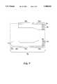
- FIG. 7is a bottom view a two rail air bearing slider in accordance with an alternative embodiment of the present invention.
- FIG. 8is a bottom view a three rail air bearing slider in accordance with another alternative embodiment of the present invention.
- FIG. 1shows a magnetic disk drive 100 utilizing an air bearing slider in accordance with the preferred embodiment of the present invention.
- a plurality of disks 101 having magnetic recording surfaces 102are rigidly attached to common hub or spindle 103, which is mounted on base 104.
- Spindle 103 and disks 101are driven by a drive motor (not visible) at a constant rotational velocity.
- Comb-like actuator assembly 105is situated to one side of disks 101.
- Actuator 105rotates through an arc about shaft 106 parallel to the axis of the spindle, driven by an electromagnet, to position the transducer heads.
- Cover 109mates with base 104 to enclose and protect the disk and actuator assemblies.
- Circuit card 112Electronic modules for controlling the operation of the drive and communicating with another device, such as a host computer, are contained in circuit card 112, typically mounted outside the enclosure.
- a plurality of head/suspension assemblies 107are rigidly attached to the prongs of actuator 105, one head/suspension assembly 107 corresponding to each disk recording surface 102. Typically, data is recorded on both surfaces of the disk, making two opposed head/suspension assemblies for each disk.
- An aerodynamic transducer head 108is located at the end of each head/suspension assembly 107 adjacent the disk surface.
- Head/suspension assembly 107is essentially a beam spring tending to force transducer head 108 against the surface of the disk 102. The aerodynamic characteristics of the head 108 counteract the force of the beam spring, making the head 108 "fly" a small distance from the surface of the disk 101 due to air movement caused by the spinning disk 101.
- Transducer head 108is shown in greater detail in FIGS. 2-6.
- Head 108comprises a transducing element mounted on an air bearing slider.
- the slideris a rectangular parallelepiped, having a plurality of rails formed on the surface facing the disk.
- the transducing elementis mounted at the rear face of the slider.
- slider 201preferably has a pair of outer rails 202 and 203, which have wide front portions 202a and 203a, respectively, and narrow rear portions 202b and 203b, respectively. Rails 202 and 203 have chamfered portions 205 and 206, respectively, at the leading edges. Slider 201 has a center rail 210, positioned midway between side rails 202 and 203 and extending rearwardly therefrom. Center rail 210 has a narrow front portion 210a which includes chamfered leading edge 207, a wide rear portion 210b and a constricted tail portion 210c.
- the transducing element (transducer gap) 215is positioned using thin film processes on the rear portion 210c of center rail 210.
- Slider 201can be fabricated using any of various conventional techniques as are known in the art.
- Slider 201is preferably formed of N58 ceramic, although other suitable ceramic or non-ceramic materials may be used.
- the pattern for the railsis preferably formed using masks, photoresists and etching to cut the slider material between the rails down several micrometers from the air bearing surfaces of the rails. Alternatively, rails can be formed by grinding out the area between the rails.
- Transducing element 215is preferably a thin-film magnetic read/write element, which is fabricated using conventional thin-film fabrication techniques. Typically, a plurality of heads are fabricated by sputtering and/or plating onto a ceramic wafer that is the thickness of the length of slider 201. The wafer is then cut into individual sliders, the wafer thickness becoming the length of the slider, and the wafer surface becoming the rear surface of the slider. Such techniques are known in the art.
- FIGS. 3-6show side and sectional views of slider 201, in which the height of the rails is exaggerated for clarity.
- the outer rails 202 and 203 of slider 201fly above the disk surface as shown in FIG. 3.
- the nominal spacing from disk surface 102is 2 to 3 microinches at the rear of the rail.
- FIG. 4is a sectional view of the slider 201 taken through center rail 210 along the line III--III of FIG. 2.
- the bottom surface of center rail 210is co-planar with the the bottom surfaces of side rails 202 and 203. Since center rail 210 extends further to the rear than either of side rails 202 or 203, the trailing end of center rail 210 is closer to the disk 102 than either of the side rails 202 or 203. Due to the upward pitch attitude at which the head 108 flies, any contact with disk 102 will occur at the rearmost portion 210c of center rail 210. Such contact will eventually wear the portion 210c of center rail 210 to a plane parallel to disk surface 102.
- the region of contactdoes not contribute to the support of the slider 201 above the disk 102, such wear does not affect the fly height of the slider 201.
- the transducer gap 215is located on the back edge of this wear region. However, since the total wear height is less than one microinch, it is small compared to the dimensions of the gap element 215.
- center rail 210The position and shape of center rail 210 when the slider 201 is first positioned over the disk 102 is shown in FIG. 5. To better illustrate the break-in process, the pitch angle has been exaggerated. It can be seen that the rearmost portion of center rail 210 is in actual contact with disk surface 102. In normal applications, the fly height will be selected so that the contact is only intermittent, and caused largely by asperities in the disk surface.
- center rail 210After the break-in period, the rearmost portion 601, shown in FIG. 6, of center rail 210 has worn to a surface parallel to the disk surface 102. The initial wear is very rapid and once it has occurred, there is very little further change in the geometry of center rail 210.
- the highest pressure under the rails 202, 203, and 210will occur near the widest point of the center rail 210.
- the pressure between center rail 210 and the disk surface 102 in region 210cwill drop considerably due to leakage from the tapered sides.
- the support for the slider 201will be virtually independent of the position and pressure under this portion 210c of the center rail 210. If portion 210c is designed to be 1.5 microinches below the position where maximum pressure exists, there will be very little change in fly height even if 1.0 microinches is worn away.
- a typical fly height drop in a slider 201 according to the inventionwould be 0.1 microinch. In this case, the back 210c of the slider 201 would have a clearance of 0.9 microinch more than when initially installed.
- slider 201 of the preferred embodimentis an application of this principle to the tri-rail slider described in U.S. Pat. No. 4,894,740 to Chhabra et al., herein incorporated by reference.
- the Chhabra tri-rail sliderprovides a reduced sensitivity to roll of the slider since, for moderate amounts of roll, the outer rails will not be lower than the back of the center rail. The remaining sensitivity is due to the remaining width of the back of the center rail, which determines how much lower one side of the rail is relative to the other for a given roll angle. With the constricted tail portion 210c of the center rail 210 as seen in FIG. 2, the roll sensitivity is further reduced compared to that of the unmodified Chhabra tri-rail. Additionally, after the initial wear, the surface will adapt to any residual static roll, so the adapted surface will be more nearly parallel to the disk surface 102.
- the inventioncan be used in varying degrees. For example, if the rearmost portion of center rails 202, 203, and 210 is made just a slightly lower than the point where maximum pressure exists, only the sliders which, due to variations within tolerance, fly slightly low would make contact with the disk. In this configuration, the sliders which fly at the specified height or slightly above would not make contact with the disk. Only those heads which perform the best, due to their exceptional closeness to the disk, would be affected since these would be flying at heights lower than the asperities. When the invention is used in this fashion, the high and nominal fly heights can be lowered without a substantial effect on the minimum fly height, which would be adapted toward the nominal value by the wear caused during a break-in period. In this situation, there would be little impact on file error rates during the break-in period since only the best performing heads are affected.
- slider 201contains three rails, the transducing element 215 being located at the rear of the center rail 210.
- the present inventioncan also be applied to slider designs having only two side rails, where the transducer is along one of the side rails.
- FIG. 7shows a bottom view of such a slider according to this alternative embodiment.
- Slider 701comprises side rails 702 and 703, which are asymmetrical. Each rail 702,703 has a corresponding chamfered leading edge 705,706. Both rails 702,703 contain respective wide leading portions 702a,703a and narrower middle portions 702b,703b.
- Rail 703additionally contains a widened rear portion 703c, and a tapered tail portion 703d.
- the transducer element 715is located on the rear face of slider 701 at the end of tail portion 703d. Tail portion 703d wears in a manner similar to tail portion 210c of slider 201 of the preferred embodiment.
- slider 801comprises symmetrical side rails 802 and 803, and center rail 810.
- Transducer 815is located at the trailing edge of center rail 810.
- Rails 802,803,810not only contain chamfered leading edges 805,806,807, respectively, but chamfered side edges 821-826 as well. Because side rails 802,803 are significantly wider than center rail 810, nearly all the aerodynamic support is provided by side rails 802,803.
- Center rail 810includes a tail portion 810a extending beyond the trailing edges of side rails 802,803. Portion 810a wears in a manner similar to tail portions 210c of slider 201 and 703d of slider 701.
- the alternative shown in FIG. 8may be particularly useful where transducer 815 is a ferrite type transducer.
- transducer 215is a thin-film magnetic read/write transducer, as is known in the art.
- the air-bearing slider of the present inventioncould be used with any of various different transducer technologies.
- transducer 215could be a ferrite transducer.
- read and write functionsbe performed by separate transducing elements, as for example a thin-film write transducer and a magneto-resistive read transducer. It should be understood that these examples are illustrative only, and the slider of the present invention could be used with transducer technologies not mentioned.
Landscapes
- Adjustment Of The Magnetic Head Position Track Following On Tapes (AREA)
Abstract
Description
Claims (13)
Priority Applications (1)
| Application Number | Priority Date | Filing Date | Title |
|---|---|---|---|
| US08/172,683US5488524A (en) | 1993-12-21 | 1993-12-21 | Self adaptive head for semi-contact recording |
Applications Claiming Priority (1)
| Application Number | Priority Date | Filing Date | Title |
|---|---|---|---|
| US08/172,683US5488524A (en) | 1993-12-21 | 1993-12-21 | Self adaptive head for semi-contact recording |
Publications (1)
| Publication Number | Publication Date |
|---|---|
| US5488524Atrue US5488524A (en) | 1996-01-30 |
Family
ID=22628743
Family Applications (1)
| Application Number | Title | Priority Date | Filing Date |
|---|---|---|---|
| US08/172,683Expired - LifetimeUS5488524A (en) | 1993-12-21 | 1993-12-21 | Self adaptive head for semi-contact recording |
Country Status (1)
| Country | Link |
|---|---|
| US (1) | US5488524A (en) |
Cited By (24)
| Publication number | Priority date | Publication date | Assignee | Title |
|---|---|---|---|---|
| US5625513A (en)* | 1994-11-14 | 1997-04-29 | Nec Corporation | Floating head slider having uniform spacing from recording medium surface |
| US5742451A (en)* | 1995-10-24 | 1998-04-21 | Tdk Corporation | Machined magnetic head with contoured air bearing surfaces |
| US5774304A (en)* | 1996-01-16 | 1998-06-30 | Seagate Technology, Inc. | Disc head slider having center rail with asymmetric edge steps |
| US5817931A (en)* | 1997-07-21 | 1998-10-06 | Seagate Technology, Inc. | Glide detect head with predictable asperity contact region |
| US5872686A (en)* | 1997-09-30 | 1999-02-16 | International Business Machines Corporation | Magnetic storage system having an improved slider having rounded corners to minimize disk damage |
| US5894379A (en)* | 1995-03-17 | 1999-04-13 | Fujitsu Limited | Magnetic head slider with rail leading portions increasing in thickness over rail portions which widen and narrow |
| US5910865A (en)* | 1997-01-15 | 1999-06-08 | Seagate Technology, Inc. | Slider having terminated side rails with trailing edge cuts |
| US5986850A (en)* | 1997-06-16 | 1999-11-16 | Seagate Technology, Inc. | Positive pressure optical slider having wide center rail |
| US6069769A (en)* | 1997-09-30 | 2000-05-30 | International Business Machines Corporation | Air bearing slider having rounded corners |
| US6075677A (en)* | 1995-07-27 | 2000-06-13 | Seagate Technology, Inc. | Method for positioning a read/write head to reduce wear for proximity recording in a magnetic disk storage system |
| US6275467B1 (en) | 1997-07-23 | 2001-08-14 | Seagate Technology Llc | Positive pressure optical slider having trailing end side pads |
| US6292332B1 (en) | 1996-01-16 | 2001-09-18 | Seagate Technology Llc | Compliant air bearing slider with wide midpoint rails for reliable proximity recording |
| US6324031B1 (en) | 1992-12-14 | 2001-11-27 | Maxtor Corporation | Disk drive with reduced electrostatic charge on slider-head assembly |
| US6493185B1 (en) | 2000-10-13 | 2002-12-10 | International Business Machines Corporation | Optimized pad design for slider and method for making the same |
| US6624984B2 (en) | 2000-05-25 | 2003-09-23 | Seagate Technology Llc | Fly height control slider with crown and cross curve de-coupling |
| US20040029488A1 (en)* | 2001-06-21 | 2004-02-12 | Smith Gordon James | Method of burnishing a burnishable rear pad slider in a disk drive |
| US6700727B1 (en) | 2000-04-14 | 2004-03-02 | Seagate Technology Llc | Slider and method for actively controlling crown curvature |
| US6714382B1 (en) | 2000-10-13 | 2004-03-30 | Hitachi Global Storage Technologies | Self-limiting wear contact pad slider and method for making the same |
| US20040082277A1 (en)* | 2001-05-25 | 2004-04-29 | Smith Gordon James | Method of burnishing a burnishable rear pad slider in a disk drive |
| US20040264052A1 (en)* | 2003-06-27 | 2004-12-30 | Seagate Technology Llc, Scotts Valley, Ca | Air bearing slider having a bearing profile contoured for pressurization proximate to nodal regions of a slider-disc interface |
| US20050197047A1 (en)* | 2000-12-06 | 2005-09-08 | Hitachi Global Storage Technologies Netherlands B.V. | Magnetic recording head burnishing method |
| US20060023354A1 (en)* | 2004-07-30 | 2006-02-02 | Stipe Barry C | Disk drive with slider burnishing-on-demand |
| US7289302B1 (en) | 2001-10-04 | 2007-10-30 | Maxtor Corporation | On slider inductors and capacitors to reduce electrostatic discharge damage |
| US9001468B2 (en)* | 2012-04-02 | 2015-04-07 | Seagate Technology Llc | Advanced air bearing slider with modulation decreasing stiffness |
Citations (17)
| Publication number | Priority date | Publication date | Assignee | Title |
|---|---|---|---|---|
| US4251841A (en)* | 1979-06-01 | 1981-02-17 | International Business Machines Corporation | Magnetic head slider assembly |
| US4555739A (en)* | 1982-11-26 | 1985-11-26 | International Business Machines Corporation | Semi self-loading ferrite head |
| US4646180A (en)* | 1982-09-30 | 1987-02-24 | Tokyo Shibaura Denki Kabushiki Kaisha | Floating head slider |
| US4777544A (en)* | 1986-08-15 | 1988-10-11 | International Business Machine Corporation | Method and apparatus for in-situ measurement of head/recording medium clearance |
| US4894740A (en)* | 1988-09-28 | 1990-01-16 | International Business Machines Corporation | Magnetic head air bearing slider |
| US4926274A (en)* | 1986-12-04 | 1990-05-15 | Kabushiki Kaisha Toshiba | Magnetic head apparatus having surfaces contoured to minimize friction between a magnetic head and a magnetic disk |
| US4931887A (en)* | 1988-02-01 | 1990-06-05 | International Business Machines Corporation | Capacitive measurement and control of the fly height of a recording slider |
| US4961121A (en)* | 1987-09-22 | 1990-10-02 | International Business Machines Corporation | Air bearing slider rail design with trumpet-shaped rail portion |
| US5021906A (en)* | 1989-10-31 | 1991-06-04 | International Business Machines Corporation | Programmable air bearing slider including magnetic read/write element |
| US5072322A (en)* | 1988-10-17 | 1991-12-10 | National Micronetics, Inc. | Monolithic ferrite recording head with glass-protected, self-aligned, machined track |
| JPH04319585A (en)* | 1991-04-18 | 1992-11-10 | Alps Electric Co Ltd | Float type magnetic head and method for manufacturing it |
| US5175658A (en)* | 1990-12-27 | 1992-12-29 | International Buiness Machines Corporation | Thin film magnetic head having a protective coating and method for making same |
| US5212608A (en)* | 1990-07-13 | 1993-05-18 | Fujitsu Limited | Head slider for magnetic disk drive, having side rails with gradually increasing width forming a shallow recess |
| US5218494A (en)* | 1990-05-25 | 1993-06-08 | Seagate Technology, Inc. | Negative pressure air bearing slider having isolation channels with edge step |
| US5287235A (en)* | 1991-10-28 | 1994-02-15 | International Business Machines Corporation | Slider air bearing surface with angled rail configuration |
| US5343343A (en)* | 1990-05-25 | 1994-08-30 | Seagate Technology, Inc. | Air bearing slider with relieved rail ends |
| US5359480A (en)* | 1992-12-21 | 1994-10-25 | Read-Rite Corporation | Magnetic head air bearing slider |
- 1993
- 1993-12-21USUS08/172,683patent/US5488524A/ennot_activeExpired - Lifetime
Patent Citations (17)
| Publication number | Priority date | Publication date | Assignee | Title |
|---|---|---|---|---|
| US4251841A (en)* | 1979-06-01 | 1981-02-17 | International Business Machines Corporation | Magnetic head slider assembly |
| US4646180A (en)* | 1982-09-30 | 1987-02-24 | Tokyo Shibaura Denki Kabushiki Kaisha | Floating head slider |
| US4555739A (en)* | 1982-11-26 | 1985-11-26 | International Business Machines Corporation | Semi self-loading ferrite head |
| US4777544A (en)* | 1986-08-15 | 1988-10-11 | International Business Machine Corporation | Method and apparatus for in-situ measurement of head/recording medium clearance |
| US4926274A (en)* | 1986-12-04 | 1990-05-15 | Kabushiki Kaisha Toshiba | Magnetic head apparatus having surfaces contoured to minimize friction between a magnetic head and a magnetic disk |
| US4961121A (en)* | 1987-09-22 | 1990-10-02 | International Business Machines Corporation | Air bearing slider rail design with trumpet-shaped rail portion |
| US4931887A (en)* | 1988-02-01 | 1990-06-05 | International Business Machines Corporation | Capacitive measurement and control of the fly height of a recording slider |
| US4894740A (en)* | 1988-09-28 | 1990-01-16 | International Business Machines Corporation | Magnetic head air bearing slider |
| US5072322A (en)* | 1988-10-17 | 1991-12-10 | National Micronetics, Inc. | Monolithic ferrite recording head with glass-protected, self-aligned, machined track |
| US5021906A (en)* | 1989-10-31 | 1991-06-04 | International Business Machines Corporation | Programmable air bearing slider including magnetic read/write element |
| US5218494A (en)* | 1990-05-25 | 1993-06-08 | Seagate Technology, Inc. | Negative pressure air bearing slider having isolation channels with edge step |
| US5343343A (en)* | 1990-05-25 | 1994-08-30 | Seagate Technology, Inc. | Air bearing slider with relieved rail ends |
| US5212608A (en)* | 1990-07-13 | 1993-05-18 | Fujitsu Limited | Head slider for magnetic disk drive, having side rails with gradually increasing width forming a shallow recess |
| US5175658A (en)* | 1990-12-27 | 1992-12-29 | International Buiness Machines Corporation | Thin film magnetic head having a protective coating and method for making same |
| JPH04319585A (en)* | 1991-04-18 | 1992-11-10 | Alps Electric Co Ltd | Float type magnetic head and method for manufacturing it |
| US5287235A (en)* | 1991-10-28 | 1994-02-15 | International Business Machines Corporation | Slider air bearing surface with angled rail configuration |
| US5359480A (en)* | 1992-12-21 | 1994-10-25 | Read-Rite Corporation | Magnetic head air bearing slider |
Non-Patent Citations (2)
| Title |
|---|
| IBM Technical Disclosure Bulletin, vol. 22, No. 4, Sep. 1979, entitled: "Flexible Disk and Self-Adaptive Head Combination" by A. J. Bowen and E. A. Cunningham. |
| IBM Technical Disclosure Bulletin, vol. 22, No. 4, Sep. 1979, entitled: Flexible Disk and Self Adaptive Head Combination by A. J. Bowen and E. A. Cunningham.* |
Cited By (33)
| Publication number | Priority date | Publication date | Assignee | Title |
|---|---|---|---|---|
| US6324031B1 (en) | 1992-12-14 | 2001-11-27 | Maxtor Corporation | Disk drive with reduced electrostatic charge on slider-head assembly |
| US6922313B1 (en)* | 1992-12-14 | 2005-07-26 | Maxtor Corporation | Magnetic head slider with resistance to debris accumulation |
| US20020034049A1 (en)* | 1992-12-14 | 2002-03-21 | Gitis Naum V. | Magnetic head slider with resistance to debris accumulation |
| US5625513A (en)* | 1994-11-14 | 1997-04-29 | Nec Corporation | Floating head slider having uniform spacing from recording medium surface |
| US5894379A (en)* | 1995-03-17 | 1999-04-13 | Fujitsu Limited | Magnetic head slider with rail leading portions increasing in thickness over rail portions which widen and narrow |
| US6231801B1 (en) | 1995-07-27 | 2001-05-15 | Seagate Technology Llc | Method to reduce wear for proximity recording in a magnetic disc storage system |
| US6075677A (en)* | 1995-07-27 | 2000-06-13 | Seagate Technology, Inc. | Method for positioning a read/write head to reduce wear for proximity recording in a magnetic disk storage system |
| US5742451A (en)* | 1995-10-24 | 1998-04-21 | Tdk Corporation | Machined magnetic head with contoured air bearing surfaces |
| US5774304A (en)* | 1996-01-16 | 1998-06-30 | Seagate Technology, Inc. | Disc head slider having center rail with asymmetric edge steps |
| US6292332B1 (en) | 1996-01-16 | 2001-09-18 | Seagate Technology Llc | Compliant air bearing slider with wide midpoint rails for reliable proximity recording |
| US5910865A (en)* | 1997-01-15 | 1999-06-08 | Seagate Technology, Inc. | Slider having terminated side rails with trailing edge cuts |
| US5986850A (en)* | 1997-06-16 | 1999-11-16 | Seagate Technology, Inc. | Positive pressure optical slider having wide center rail |
| US5817931A (en)* | 1997-07-21 | 1998-10-06 | Seagate Technology, Inc. | Glide detect head with predictable asperity contact region |
| US6275467B1 (en) | 1997-07-23 | 2001-08-14 | Seagate Technology Llc | Positive pressure optical slider having trailing end side pads |
| US6069769A (en)* | 1997-09-30 | 2000-05-30 | International Business Machines Corporation | Air bearing slider having rounded corners |
| US5872686A (en)* | 1997-09-30 | 1999-02-16 | International Business Machines Corporation | Magnetic storage system having an improved slider having rounded corners to minimize disk damage |
| US6700727B1 (en) | 2000-04-14 | 2004-03-02 | Seagate Technology Llc | Slider and method for actively controlling crown curvature |
| US6624984B2 (en) | 2000-05-25 | 2003-09-23 | Seagate Technology Llc | Fly height control slider with crown and cross curve de-coupling |
| US7029590B2 (en) | 2000-10-13 | 2006-04-18 | Hitachi Global Storage Technologies Netherlands B.V. | Self-limiting wear contact pad slider and method for making the same |
| US6493185B1 (en) | 2000-10-13 | 2002-12-10 | International Business Machines Corporation | Optimized pad design for slider and method for making the same |
| US6714382B1 (en) | 2000-10-13 | 2004-03-30 | Hitachi Global Storage Technologies | Self-limiting wear contact pad slider and method for making the same |
| US7094129B2 (en)* | 2000-12-06 | 2006-08-22 | Hitachi Global Storage Technologies Netherlands B.V. | Magnetic recording head burnishing method |
| US20050197047A1 (en)* | 2000-12-06 | 2005-09-08 | Hitachi Global Storage Technologies Netherlands B.V. | Magnetic recording head burnishing method |
| US6852013B2 (en) | 2001-05-25 | 2005-02-08 | Hitachi Global Storage Technologies Netherlands B.V. | Method of burnishing a burnishable rear pad slider in a disk drive |
| US20040082277A1 (en)* | 2001-05-25 | 2004-04-29 | Smith Gordon James | Method of burnishing a burnishable rear pad slider in a disk drive |
| US6896592B2 (en) | 2001-06-21 | 2005-05-24 | Hitachi Global Storage Technologies Netherlands B.V. | Method of burnishing a burnishable rear pad slider in a disk drive |
| US20040029488A1 (en)* | 2001-06-21 | 2004-02-12 | Smith Gordon James | Method of burnishing a burnishable rear pad slider in a disk drive |
| US7289302B1 (en) | 2001-10-04 | 2007-10-30 | Maxtor Corporation | On slider inductors and capacitors to reduce electrostatic discharge damage |
| US20040264052A1 (en)* | 2003-06-27 | 2004-12-30 | Seagate Technology Llc, Scotts Valley, Ca | Air bearing slider having a bearing profile contoured for pressurization proximate to nodal regions of a slider-disc interface |
| US7190550B2 (en)* | 2003-06-27 | 2007-03-13 | Seagate Technology Llc | Air bearing slider having a bearing profile contoured for pressurization proximate to nodal regions of a slider-disc interface |
| US20060023354A1 (en)* | 2004-07-30 | 2006-02-02 | Stipe Barry C | Disk drive with slider burnishing-on-demand |
| US7362533B2 (en) | 2004-07-30 | 2008-04-22 | Hitachi Global Storage Technologies Netherlands B.V. | Disk drive with slider burnishing-on-demand |
| US9001468B2 (en)* | 2012-04-02 | 2015-04-07 | Seagate Technology Llc | Advanced air bearing slider with modulation decreasing stiffness |
Similar Documents
| Publication | Publication Date | Title |
|---|---|---|
| US5488524A (en) | Self adaptive head for semi-contact recording | |
| US5940249A (en) | Shielded air bearing slider | |
| US5327310A (en) | Thin film contact recording head | |
| US5198934A (en) | Magnetic disk device including a slider provided with a solid protecting layer which determines the distance between a magnetic gap and a magnetic disk recording device | |
| USRE39004E1 (en) | Pseudo contact type negative pressure air bearing slider | |
| EP0938081B1 (en) | Pseudo contact negative pressure air bearing slider with divided negative pressure pockets | |
| KR970006867B1 (en) | Air bearing slider | |
| US6144528A (en) | Air bearing slider with reduced stiction | |
| US6160683A (en) | Slider for disc storage system | |
| US6137656A (en) | Air bearing slider | |
| US5708540A (en) | Slider for inhibiting stiction and with backbar | |
| EP0361658B1 (en) | Magnetic recording apparatus with magnetic head air bearing slider | |
| US6956718B1 (en) | Sandwich diamond-like carbon overcoat for use in slider designs of proximity recording heads | |
| US6014288A (en) | Partially etched protective overcoat for a disk drive slider | |
| EP0936599B1 (en) | Flying negative pressure air bearing slider with divided negative pressure pockets | |
| US6128163A (en) | Disk drive including slider with recessed magneto-resistive transducer | |
| US6243222B1 (en) | Load/unload method for sliders in a high speed disk drive | |
| US5872685A (en) | Flying-type negative pressure air bearing slider | |
| US6950281B2 (en) | Negative pressure type head slider and disk drive | |
| US20020071216A1 (en) | Disc drive having an air bearing surface with trenched contact protection feature | |
| WO2002084650A1 (en) | Air bearing slider | |
| US6654205B1 (en) | Air bearing surface for reducing pressure gradients | |
| EP0793229B1 (en) | Air bearing surface features for optimized transducer spacing | |
| US6608735B1 (en) | Asymmetric tapered air bearing slider | |
| US20040075947A1 (en) | Head slider |
Legal Events
| Date | Code | Title | Description |
|---|---|---|---|
| AS | Assignment | Owner name:INTERNATIONAL BUSINESS MACHINES CORPORATION, NEW Y Free format text:ASSIGNMENT OF ASSIGNORS INTEREST;ASSIGNOR:CUNNINGHAM, EARL A.;REEL/FRAME:006862/0361 Effective date:19940107 | |
| STCF | Information on status: patent grant | Free format text:PATENTED CASE | |
| FPAY | Fee payment | Year of fee payment:4 | |
| FEPP | Fee payment procedure | Free format text:PAYOR NUMBER ASSIGNED (ORIGINAL EVENT CODE: ASPN); ENTITY STATUS OF PATENT OWNER: LARGE ENTITY | |
| AS | Assignment | Owner name:MARIANA HDD B.V., NETHERLANDS Free format text:ASSIGNMENT OF ASSIGNORS INTEREST;ASSIGNOR:INTERNATIONAL BUSINESS MACHINES CORPORATION;REEL/FRAME:013663/0348 Effective date:20021231 | |
| AS | Assignment | Owner name:HITACHI GLOBAL STORAGE TECHNOLOGIES NETHERLANDS B. Free format text:CHANGE OF NAME;ASSIGNOR:MARIANA HDD B.V.;REEL/FRAME:013746/0146 Effective date:20021231 | |
| FPAY | Fee payment | Year of fee payment:8 | |
| FPAY | Fee payment | Year of fee payment:12 | |
| AS | Assignment | Owner name:HGST, NETHERLANDS B.V., NETHERLANDS Free format text:CHANGE OF NAME;ASSIGNOR:HGST, NETHERLANDS B.V.;REEL/FRAME:029341/0777 Effective date:20120723 Owner name:HGST NETHERLANDS B.V., NETHERLANDS Free format text:CHANGE OF NAME;ASSIGNOR:HITACHI GLOBAL STORAGE TECHNOLOGIES NETHERLANDS B.V.;REEL/FRAME:029341/0777 Effective date:20120723 |