US5487734A - Self retracting catheter needle apparatus and methods - Google Patents
Self retracting catheter needle apparatus and methodsDownload PDFInfo
- Publication number
- US5487734A US5487734AUS08/436,976US43697695AUS5487734AUS 5487734 AUS5487734 AUS 5487734AUS 43697695 AUS43697695 AUS 43697695AUS 5487734 AUS5487734 AUS 5487734A
- Authority
- US
- United States
- Prior art keywords
- needle
- catheter
- housing
- hub
- disposed
- Prior art date
- Legal status (The legal status is an assumption and is not a legal conclusion. Google has not performed a legal analysis and makes no representation as to the accuracy of the status listed.)
- Expired - Lifetime
Links
- 238000000034methodMethods0.000titleclaimsabstractdescription38
- 210000004369bloodAnatomy0.000claimsabstractdescription51
- 239000008280bloodSubstances0.000claimsabstractdescription51
- 238000003780insertionMethods0.000claimsabstractdescription28
- 230000037431insertionEffects0.000claimsabstractdescription28
- 230000007246mechanismEffects0.000claimsabstractdescription23
- 239000000463materialSubstances0.000claimsdescription28
- 230000037361pathwayEffects0.000claimsdescription21
- 239000012530fluidSubstances0.000claimsdescription11
- 210000004204blood vesselAnatomy0.000claimsdescription10
- 230000001681protective effectEffects0.000claimsdescription7
- 230000000881depressing effectEffects0.000claimsdescription4
- 238000004891communicationMethods0.000claimsdescription3
- 230000000717retained effectEffects0.000claimsdescription2
- 230000004888barrier functionEffects0.000claims1
- 238000004519manufacturing processMethods0.000abstractdescription9
- 230000002860competitive effectEffects0.000abstractdescription5
- 230000017531blood circulationEffects0.000abstractdescription3
- 230000008569processEffects0.000description11
- 230000006870functionEffects0.000description10
- 238000002347injectionMethods0.000description10
- 239000007924injectionSubstances0.000description10
- 238000000465mouldingMethods0.000description9
- 239000003566sealing materialSubstances0.000description9
- 239000000853adhesiveSubstances0.000description7
- 230000001070adhesive effectEffects0.000description7
- 208000012266Needlestick injuryDiseases0.000description5
- 208000027418Wounds and injuryDiseases0.000description5
- 239000012260resinous materialSubstances0.000description5
- 206010052428WoundDiseases0.000description4
- 230000009471actionEffects0.000description4
- 230000006835compressionEffects0.000description4
- 238000007906compressionMethods0.000description4
- 230000036512infertilityEffects0.000description4
- 230000000087stabilizing effectEffects0.000description4
- 210000003813thumbAnatomy0.000description4
- 238000010241blood samplingMethods0.000description3
- 230000000295complement effectEffects0.000description3
- 230000008878couplingEffects0.000description3
- 238000010168coupling processMethods0.000description3
- 238000005859coupling reactionMethods0.000description3
- 238000006073displacement reactionMethods0.000description3
- 229920001821foam rubberPolymers0.000description3
- 210000005224forefingerAnatomy0.000description3
- -1polypropylenePolymers0.000description3
- 229920001651CyanoacrylatePolymers0.000description2
- 239000004698PolyethyleneSubstances0.000description2
- 239000004830Super GlueSubstances0.000description2
- 230000008901benefitEffects0.000description2
- 230000008602contractionEffects0.000description2
- 238000005304joiningMethods0.000description2
- 239000004816latexSubstances0.000description2
- 229920000126latexPolymers0.000description2
- 239000007788liquidSubstances0.000description2
- 229940127554medical productDrugs0.000description2
- 238000004806packaging method and processMethods0.000description2
- 239000004033plasticSubstances0.000description2
- 229920003023plasticPolymers0.000description2
- 229920000573polyethylenePolymers0.000description2
- 229920002635polyurethanePolymers0.000description2
- 239000004814polyurethaneSubstances0.000description2
- 238000003825pressingMethods0.000description2
- 230000002829reductive effectEffects0.000description2
- 230000001960triggered effectEffects0.000description2
- 238000003466weldingMethods0.000description2
- 208000030507AIDSDiseases0.000description1
- 229920000544Gore-TexPolymers0.000description1
- 239000004743PolypropyleneSubstances0.000description1
- 241000612182Rexea solandriSpecies0.000description1
- 229910000831SteelInorganic materials0.000description1
- 230000000903blocking effectEffects0.000description1
- 239000010836blood and blood productSubstances0.000description1
- 229940125691blood productDrugs0.000description1
- 238000011109contaminationMethods0.000description1
- 238000012864cross contaminationMethods0.000description1
- 230000006378damageEffects0.000description1
- 230000001419dependent effectEffects0.000description1
- 230000000994depressogenic effectEffects0.000description1
- 239000003814drugSubstances0.000description1
- 229940079593drugDrugs0.000description1
- 239000013013elastic materialSubstances0.000description1
- 210000003414extremityAnatomy0.000description1
- 210000003811fingerAnatomy0.000description1
- 208000006454hepatitisDiseases0.000description1
- 231100000283hepatitisToxicity0.000description1
- 230000002209hydrophobic effectEffects0.000description1
- 230000006872improvementEffects0.000description1
- 238000001802infusionMethods0.000description1
- 208000014674injuryDiseases0.000description1
- 239000012528membraneSubstances0.000description1
- 230000006996mental stateEffects0.000description1
- 230000008450motivationEffects0.000description1
- 229920001155polypropylenePolymers0.000description1
- 230000002250progressing effectEffects0.000description1
- 230000000284resting effectEffects0.000description1
- 230000000979retarding effectEffects0.000description1
- 238000000926separation methodMethods0.000description1
- 239000000243solutionSubstances0.000description1
- 239000010959steelSubstances0.000description1
- 238000006467substitution reactionMethods0.000description1
- 239000012780transparent materialSubstances0.000description1
- 238000011144upstream manufacturingMethods0.000description1
- 230000035899viabilityEffects0.000description1
- XLYOFNOQVPJJNP-UHFFFAOYSA-NwaterSubstancesOXLYOFNOQVPJJNP-UHFFFAOYSA-N0.000description1
Images


Classifications
- A—HUMAN NECESSITIES
- A61—MEDICAL OR VETERINARY SCIENCE; HYGIENE
- A61B—DIAGNOSIS; SURGERY; IDENTIFICATION
- A61B5/00—Measuring for diagnostic purposes; Identification of persons
- A61B5/15—Devices for taking samples of blood
- A61B5/150007—Details
- A61B5/150374—Details of piercing elements or protective means for preventing accidental injuries by such piercing elements
- A61B5/150381—Design of piercing elements
- A61B5/150473—Double-ended needles, e.g. used with pre-evacuated sampling tubes
- A61B5/150488—Details of construction of shaft
- A—HUMAN NECESSITIES
- A61—MEDICAL OR VETERINARY SCIENCE; HYGIENE
- A61B—DIAGNOSIS; SURGERY; IDENTIFICATION
- A61B5/00—Measuring for diagnostic purposes; Identification of persons
- A61B5/15—Devices for taking samples of blood
- A61B5/150007—Details
- A61B5/150015—Source of blood
- A61B5/15003—Source of blood for venous or arterial blood
- A—HUMAN NECESSITIES
- A61—MEDICAL OR VETERINARY SCIENCE; HYGIENE
- A61B—DIAGNOSIS; SURGERY; IDENTIFICATION
- A61B5/00—Measuring for diagnostic purposes; Identification of persons
- A61B5/15—Devices for taking samples of blood
- A61B5/150007—Details
- A61B5/150206—Construction or design features not otherwise provided for; manufacturing or production; packages; sterilisation of piercing element, piercing device or sampling device
- A61B5/150259—Improved gripping, e.g. with high friction pattern or projections on the housing surface or an ergonometric shape
- A—HUMAN NECESSITIES
- A61—MEDICAL OR VETERINARY SCIENCE; HYGIENE
- A61B—DIAGNOSIS; SURGERY; IDENTIFICATION
- A61B5/00—Measuring for diagnostic purposes; Identification of persons
- A61B5/15—Devices for taking samples of blood
- A61B5/150007—Details
- A61B5/150206—Construction or design features not otherwise provided for; manufacturing or production; packages; sterilisation of piercing element, piercing device or sampling device
- A61B5/150274—Manufacture or production processes or steps for blood sampling devices
- A—HUMAN NECESSITIES
- A61—MEDICAL OR VETERINARY SCIENCE; HYGIENE
- A61B—DIAGNOSIS; SURGERY; IDENTIFICATION
- A61B5/00—Measuring for diagnostic purposes; Identification of persons
- A61B5/15—Devices for taking samples of blood
- A61B5/150007—Details
- A61B5/150206—Construction or design features not otherwise provided for; manufacturing or production; packages; sterilisation of piercing element, piercing device or sampling device
- A61B5/150305—Packages specially adapted for piercing devices or blood sampling devices
- A—HUMAN NECESSITIES
- A61—MEDICAL OR VETERINARY SCIENCE; HYGIENE
- A61B—DIAGNOSIS; SURGERY; IDENTIFICATION
- A61B5/00—Measuring for diagnostic purposes; Identification of persons
- A61B5/15—Devices for taking samples of blood
- A61B5/150007—Details
- A61B5/150351—Caps, stoppers or lids for sealing or closing a blood collection vessel or container, e.g. a test-tube or syringe barrel
- A—HUMAN NECESSITIES
- A61—MEDICAL OR VETERINARY SCIENCE; HYGIENE
- A61B—DIAGNOSIS; SURGERY; IDENTIFICATION
- A61B5/00—Measuring for diagnostic purposes; Identification of persons
- A61B5/15—Devices for taking samples of blood
- A61B5/150007—Details
- A61B5/150374—Details of piercing elements or protective means for preventing accidental injuries by such piercing elements
- A61B5/150381—Design of piercing elements
- A61B5/150389—Hollow piercing elements, e.g. canulas, needles, for piercing the skin
- A—HUMAN NECESSITIES
- A61—MEDICAL OR VETERINARY SCIENCE; HYGIENE
- A61B—DIAGNOSIS; SURGERY; IDENTIFICATION
- A61B5/00—Measuring for diagnostic purposes; Identification of persons
- A61B5/15—Devices for taking samples of blood
- A61B5/150007—Details
- A61B5/150374—Details of piercing elements or protective means for preventing accidental injuries by such piercing elements
- A61B5/150381—Design of piercing elements
- A61B5/150473—Double-ended needles, e.g. used with pre-evacuated sampling tubes
- A61B5/150496—Details of construction of hub, i.e. element used to attach the double-ended needle to a piercing device or sampling device
- A—HUMAN NECESSITIES
- A61—MEDICAL OR VETERINARY SCIENCE; HYGIENE
- A61B—DIAGNOSIS; SURGERY; IDENTIFICATION
- A61B5/00—Measuring for diagnostic purposes; Identification of persons
- A61B5/15—Devices for taking samples of blood
- A61B5/150007—Details
- A61B5/150374—Details of piercing elements or protective means for preventing accidental injuries by such piercing elements
- A61B5/150381—Design of piercing elements
- A61B5/150503—Single-ended needles
- A61B5/150519—Details of construction of hub, i.e. element used to attach the single-ended needle to a piercing device or sampling device
- A—HUMAN NECESSITIES
- A61—MEDICAL OR VETERINARY SCIENCE; HYGIENE
- A61B—DIAGNOSIS; SURGERY; IDENTIFICATION
- A61B5/00—Measuring for diagnostic purposes; Identification of persons
- A61B5/15—Devices for taking samples of blood
- A61B5/150007—Details
- A61B5/150374—Details of piercing elements or protective means for preventing accidental injuries by such piercing elements
- A61B5/150534—Design of protective means for piercing elements for preventing accidental needle sticks, e.g. shields, caps, protectors, axially extensible sleeves, pivotable protective sleeves
- A61B5/150572—Pierceable protectors, e.g. shields, caps, sleeves or films, e.g. for hygienic purposes
- A—HUMAN NECESSITIES
- A61—MEDICAL OR VETERINARY SCIENCE; HYGIENE
- A61B—DIAGNOSIS; SURGERY; IDENTIFICATION
- A61B5/00—Measuring for diagnostic purposes; Identification of persons
- A61B5/15—Devices for taking samples of blood
- A61B5/150007—Details
- A61B5/150374—Details of piercing elements or protective means for preventing accidental injuries by such piercing elements
- A61B5/150534—Design of protective means for piercing elements for preventing accidental needle sticks, e.g. shields, caps, protectors, axially extensible sleeves, pivotable protective sleeves
- A61B5/15058—Joining techniques used for protective means
- A61B5/150603—Joining techniques used for protective means by rotation, e.g. bayonet or screw
- A—HUMAN NECESSITIES
- A61—MEDICAL OR VETERINARY SCIENCE; HYGIENE
- A61B—DIAGNOSIS; SURGERY; IDENTIFICATION
- A61B5/00—Measuring for diagnostic purposes; Identification of persons
- A61B5/15—Devices for taking samples of blood
- A61B5/150007—Details
- A61B5/150732—Needle holders, for instance for holding the needle by the hub, used for example with double-ended needle and pre-evacuated tube
- A—HUMAN NECESSITIES
- A61—MEDICAL OR VETERINARY SCIENCE; HYGIENE
- A61B—DIAGNOSIS; SURGERY; IDENTIFICATION
- A61B5/00—Measuring for diagnostic purposes; Identification of persons
- A61B5/15—Devices for taking samples of blood
- A61B5/150007—Details
- A61B5/150885—Preventing re-use
- A61B5/150908—Preventing re-use by disconnecting components, e.g. breaking or rupturing of connected parts, e.g. piston and rod
- A—HUMAN NECESSITIES
- A61—MEDICAL OR VETERINARY SCIENCE; HYGIENE
- A61B—DIAGNOSIS; SURGERY; IDENTIFICATION
- A61B5/00—Measuring for diagnostic purposes; Identification of persons
- A61B5/15—Devices for taking samples of blood
- A61B5/153—Devices specially adapted for taking samples of venous or arterial blood, e.g. with syringes
- A—HUMAN NECESSITIES
- A61—MEDICAL OR VETERINARY SCIENCE; HYGIENE
- A61M—DEVICES FOR INTRODUCING MEDIA INTO, OR ONTO, THE BODY; DEVICES FOR TRANSDUCING BODY MEDIA OR FOR TAKING MEDIA FROM THE BODY; DEVICES FOR PRODUCING OR ENDING SLEEP OR STUPOR
- A61M25/00—Catheters; Hollow probes
- A61M25/01—Introducing, guiding, advancing, emplacing or holding catheters
- A61M25/06—Body-piercing guide needles or the like
- A61M25/0612—Devices for protecting the needle; Devices to help insertion of the needle, e.g. wings or holders
- A61M25/0631—Devices for protecting the needle; Devices to help insertion of the needle, e.g. wings or holders having means for fully covering the needle after its withdrawal, e.g. needle being withdrawn inside the handle or a cover being advanced over the needle
- A—HUMAN NECESSITIES
- A61—MEDICAL OR VETERINARY SCIENCE; HYGIENE
- A61M—DEVICES FOR INTRODUCING MEDIA INTO, OR ONTO, THE BODY; DEVICES FOR TRANSDUCING BODY MEDIA OR FOR TAKING MEDIA FROM THE BODY; DEVICES FOR PRODUCING OR ENDING SLEEP OR STUPOR
- A61M5/00—Devices for bringing media into the body in a subcutaneous, intra-vascular or intramuscular way; Accessories therefor, e.g. filling or cleaning devices, arm-rests
- A61M5/178—Syringes
- A61M5/28—Syringe ampoules or carpules, i.e. ampoules or carpules provided with a needle
- A61M5/281—Syringe ampoules or carpules, i.e. ampoules or carpules provided with a needle using emptying means to expel or eject media, e.g. pistons, deformation of the ampoule, or telescoping of the ampoule
- A61M5/283—Syringe ampoules or carpules, i.e. ampoules or carpules provided with a needle using emptying means to expel or eject media, e.g. pistons, deformation of the ampoule, or telescoping of the ampoule by telescoping of ampoules or carpules with the syringe body
- A—HUMAN NECESSITIES
- A61—MEDICAL OR VETERINARY SCIENCE; HYGIENE
- A61M—DEVICES FOR INTRODUCING MEDIA INTO, OR ONTO, THE BODY; DEVICES FOR TRANSDUCING BODY MEDIA OR FOR TAKING MEDIA FROM THE BODY; DEVICES FOR PRODUCING OR ENDING SLEEP OR STUPOR
- A61M5/00—Devices for bringing media into the body in a subcutaneous, intra-vascular or intramuscular way; Accessories therefor, e.g. filling or cleaning devices, arm-rests
- A61M5/178—Syringes
- A61M5/31—Details
- A61M5/32—Needles; Details of needles pertaining to their connection with syringe or hub; Accessories for bringing the needle into, or holding the needle on, the body; Devices for protection of needles
- A61M5/3205—Apparatus for removing or disposing of used needles or syringes, e.g. containers; Means for protection against accidental injuries from used needles
- A61M5/321—Means for protection against accidental injuries by used needles
- A61M5/322—Retractable needles, i.e. disconnected from and withdrawn into the syringe barrel by the piston
- A61M5/3234—Fully automatic needle retraction, i.e. in which triggering of the needle does not require a deliberate action by the user
- A—HUMAN NECESSITIES
- A61—MEDICAL OR VETERINARY SCIENCE; HYGIENE
- A61B—DIAGNOSIS; SURGERY; IDENTIFICATION
- A61B5/00—Measuring for diagnostic purposes; Identification of persons
- A61B5/15—Devices for taking samples of blood
- A61B5/150007—Details
- A61B5/150374—Details of piercing elements or protective means for preventing accidental injuries by such piercing elements
- A61B5/150534—Design of protective means for piercing elements for preventing accidental needle sticks, e.g. shields, caps, protectors, axially extensible sleeves, pivotable protective sleeves
- A61B5/150633—Protective sleeves which are axially extensible, e.g. sleeves connected to, or integrated in, the piercing or driving device; pivotable protective sleeves
- A—HUMAN NECESSITIES
- A61—MEDICAL OR VETERINARY SCIENCE; HYGIENE
- A61M—DEVICES FOR INTRODUCING MEDIA INTO, OR ONTO, THE BODY; DEVICES FOR TRANSDUCING BODY MEDIA OR FOR TAKING MEDIA FROM THE BODY; DEVICES FOR PRODUCING OR ENDING SLEEP OR STUPOR
- A61M5/00—Devices for bringing media into the body in a subcutaneous, intra-vascular or intramuscular way; Accessories therefor, e.g. filling or cleaning devices, arm-rests
- A61M5/178—Syringes
- A61M5/31—Details
- A61M2005/3101—Leak prevention means for proximal end of syringes, i.e. syringe end opposite to needle mounting end
- A—HUMAN NECESSITIES
- A61—MEDICAL OR VETERINARY SCIENCE; HYGIENE
- A61M—DEVICES FOR INTRODUCING MEDIA INTO, OR ONTO, THE BODY; DEVICES FOR TRANSDUCING BODY MEDIA OR FOR TAKING MEDIA FROM THE BODY; DEVICES FOR PRODUCING OR ENDING SLEEP OR STUPOR
- A61M5/00—Devices for bringing media into the body in a subcutaneous, intra-vascular or intramuscular way; Accessories therefor, e.g. filling or cleaning devices, arm-rests
- A61M5/178—Syringes
- A61M5/31—Details
- A61M2005/3103—Leak prevention means for distal end of syringes, i.e. syringe end for mounting a needle
- A61M2005/3106—Plugs for syringes without needle
- A—HUMAN NECESSITIES
- A61—MEDICAL OR VETERINARY SCIENCE; HYGIENE
- A61M—DEVICES FOR INTRODUCING MEDIA INTO, OR ONTO, THE BODY; DEVICES FOR TRANSDUCING BODY MEDIA OR FOR TAKING MEDIA FROM THE BODY; DEVICES FOR PRODUCING OR ENDING SLEEP OR STUPOR
- A61M5/00—Devices for bringing media into the body in a subcutaneous, intra-vascular or intramuscular way; Accessories therefor, e.g. filling or cleaning devices, arm-rests
- A61M5/178—Syringes
- A61M5/31—Details
- A61M2005/3117—Means preventing contamination of the medicament compartment of a syringe
- A61M2005/3121—Means preventing contamination of the medicament compartment of a syringe via the proximal end of a syringe, i.e. syringe end opposite to needle cannula mounting end
- A—HUMAN NECESSITIES
- A61—MEDICAL OR VETERINARY SCIENCE; HYGIENE
- A61M—DEVICES FOR INTRODUCING MEDIA INTO, OR ONTO, THE BODY; DEVICES FOR TRANSDUCING BODY MEDIA OR FOR TAKING MEDIA FROM THE BODY; DEVICES FOR PRODUCING OR ENDING SLEEP OR STUPOR
- A61M5/00—Devices for bringing media into the body in a subcutaneous, intra-vascular or intramuscular way; Accessories therefor, e.g. filling or cleaning devices, arm-rests
- A61M5/178—Syringes
- A61M5/31—Details
- A61M5/32—Needles; Details of needles pertaining to their connection with syringe or hub; Accessories for bringing the needle into, or holding the needle on, the body; Devices for protection of needles
- A61M5/3205—Apparatus for removing or disposing of used needles or syringes, e.g. containers; Means for protection against accidental injuries from used needles
- A61M2005/3206—Needle or needle hub disconnecting devices forming part of or being attached to the hub or syringe body
- A—HUMAN NECESSITIES
- A61—MEDICAL OR VETERINARY SCIENCE; HYGIENE
- A61M—DEVICES FOR INTRODUCING MEDIA INTO, OR ONTO, THE BODY; DEVICES FOR TRANSDUCING BODY MEDIA OR FOR TAKING MEDIA FROM THE BODY; DEVICES FOR PRODUCING OR ENDING SLEEP OR STUPOR
- A61M5/00—Devices for bringing media into the body in a subcutaneous, intra-vascular or intramuscular way; Accessories therefor, e.g. filling or cleaning devices, arm-rests
- A61M5/178—Syringes
- A61M5/31—Details
- A61M5/32—Needles; Details of needles pertaining to their connection with syringe or hub; Accessories for bringing the needle into, or holding the needle on, the body; Devices for protection of needles
- A61M5/3205—Apparatus for removing or disposing of used needles or syringes, e.g. containers; Means for protection against accidental injuries from used needles
- A61M5/321—Means for protection against accidental injuries by used needles
- A61M5/322—Retractable needles, i.e. disconnected from and withdrawn into the syringe barrel by the piston
- A61M5/3221—Constructional features thereof, e.g. to improve manipulation or functioning
- A61M2005/3223—Means impeding or disabling repositioning of used needles at the syringe nozzle
- A61M2005/3224—Means to disalign the needle tip and syringe nozzle
- A—HUMAN NECESSITIES
- A61—MEDICAL OR VETERINARY SCIENCE; HYGIENE
- A61M—DEVICES FOR INTRODUCING MEDIA INTO, OR ONTO, THE BODY; DEVICES FOR TRANSDUCING BODY MEDIA OR FOR TAKING MEDIA FROM THE BODY; DEVICES FOR PRODUCING OR ENDING SLEEP OR STUPOR
- A61M5/00—Devices for bringing media into the body in a subcutaneous, intra-vascular or intramuscular way; Accessories therefor, e.g. filling or cleaning devices, arm-rests
- A61M5/178—Syringes
- A61M5/31—Details
- A61M5/32—Needles; Details of needles pertaining to their connection with syringe or hub; Accessories for bringing the needle into, or holding the needle on, the body; Devices for protection of needles
- A61M5/3205—Apparatus for removing or disposing of used needles or syringes, e.g. containers; Means for protection against accidental injuries from used needles
- A61M5/321—Means for protection against accidental injuries by used needles
- A61M5/322—Retractable needles, i.e. disconnected from and withdrawn into the syringe barrel by the piston
- A61M5/3221—Constructional features thereof, e.g. to improve manipulation or functioning
- A61M2005/3223—Means impeding or disabling repositioning of used needles at the syringe nozzle
- A61M2005/3226—Means impeding or disabling repositioning of used needles at the syringe nozzle with means obstructing or blocking the needle mounting opening
- A—HUMAN NECESSITIES
- A61—MEDICAL OR VETERINARY SCIENCE; HYGIENE
- A61M—DEVICES FOR INTRODUCING MEDIA INTO, OR ONTO, THE BODY; DEVICES FOR TRANSDUCING BODY MEDIA OR FOR TAKING MEDIA FROM THE BODY; DEVICES FOR PRODUCING OR ENDING SLEEP OR STUPOR
- A61M5/00—Devices for bringing media into the body in a subcutaneous, intra-vascular or intramuscular way; Accessories therefor, e.g. filling or cleaning devices, arm-rests
- A61M5/178—Syringes
- A61M5/31—Details
- A61M5/32—Needles; Details of needles pertaining to their connection with syringe or hub; Accessories for bringing the needle into, or holding the needle on, the body; Devices for protection of needles
- A61M5/3205—Apparatus for removing or disposing of used needles or syringes, e.g. containers; Means for protection against accidental injuries from used needles
- A61M5/321—Means for protection against accidental injuries by used needles
- A61M5/322—Retractable needles, i.e. disconnected from and withdrawn into the syringe barrel by the piston
- A61M5/3234—Fully automatic needle retraction, i.e. in which triggering of the needle does not require a deliberate action by the user
- A61M2005/3241—Needle retraction energy is accumulated inside of a hollow plunger rod
- A61M2005/3242—Needle retraction by vacuum
- A—HUMAN NECESSITIES
- A61—MEDICAL OR VETERINARY SCIENCE; HYGIENE
- A61M—DEVICES FOR INTRODUCING MEDIA INTO, OR ONTO, THE BODY; DEVICES FOR TRANSDUCING BODY MEDIA OR FOR TAKING MEDIA FROM THE BODY; DEVICES FOR PRODUCING OR ENDING SLEEP OR STUPOR
- A61M5/00—Devices for bringing media into the body in a subcutaneous, intra-vascular or intramuscular way; Accessories therefor, e.g. filling or cleaning devices, arm-rests
- A61M5/178—Syringes
- A61M5/31—Details
- A61M5/32—Needles; Details of needles pertaining to their connection with syringe or hub; Accessories for bringing the needle into, or holding the needle on, the body; Devices for protection of needles
- A61M5/3205—Apparatus for removing or disposing of used needles or syringes, e.g. containers; Means for protection against accidental injuries from used needles
- A61M5/321—Means for protection against accidental injuries by used needles
- A61M5/3243—Means for protection against accidental injuries by used needles being axially-extensible, e.g. protective sleeves coaxially slidable on the syringe barrel
- A61M5/3245—Constructional features thereof, e.g. to improve manipulation or functioning
- A61M2005/3247—Means to impede repositioning of protection sleeve from needle covering to needle uncovering position
- A—HUMAN NECESSITIES
- A61—MEDICAL OR VETERINARY SCIENCE; HYGIENE
- A61M—DEVICES FOR INTRODUCING MEDIA INTO, OR ONTO, THE BODY; DEVICES FOR TRANSDUCING BODY MEDIA OR FOR TAKING MEDIA FROM THE BODY; DEVICES FOR PRODUCING OR ENDING SLEEP OR STUPOR
- A61M25/00—Catheters; Hollow probes
- A61M25/01—Introducing, guiding, advancing, emplacing or holding catheters
- A61M25/06—Body-piercing guide needles or the like
- A61M25/0612—Devices for protecting the needle; Devices to help insertion of the needle, e.g. wings or holders
- A—HUMAN NECESSITIES
- A61—MEDICAL OR VETERINARY SCIENCE; HYGIENE
- A61M—DEVICES FOR INTRODUCING MEDIA INTO, OR ONTO, THE BODY; DEVICES FOR TRANSDUCING BODY MEDIA OR FOR TAKING MEDIA FROM THE BODY; DEVICES FOR PRODUCING OR ENDING SLEEP OR STUPOR
- A61M5/00—Devices for bringing media into the body in a subcutaneous, intra-vascular or intramuscular way; Accessories therefor, e.g. filling or cleaning devices, arm-rests
- A61M5/178—Syringes
- A61M5/31—Details
- A61M5/32—Needles; Details of needles pertaining to their connection with syringe or hub; Accessories for bringing the needle into, or holding the needle on, the body; Devices for protection of needles
- A61M5/3202—Devices for protection of the needle before use, e.g. caps
- A—HUMAN NECESSITIES
- A61—MEDICAL OR VETERINARY SCIENCE; HYGIENE
- A61M—DEVICES FOR INTRODUCING MEDIA INTO, OR ONTO, THE BODY; DEVICES FOR TRANSDUCING BODY MEDIA OR FOR TAKING MEDIA FROM THE BODY; DEVICES FOR PRODUCING OR ENDING SLEEP OR STUPOR
- A61M5/00—Devices for bringing media into the body in a subcutaneous, intra-vascular or intramuscular way; Accessories therefor, e.g. filling or cleaning devices, arm-rests
- A61M5/178—Syringes
- A61M5/31—Details
- A61M5/32—Needles; Details of needles pertaining to their connection with syringe or hub; Accessories for bringing the needle into, or holding the needle on, the body; Devices for protection of needles
- A61M5/3205—Apparatus for removing or disposing of used needles or syringes, e.g. containers; Means for protection against accidental injuries from used needles
- A61M5/321—Means for protection against accidental injuries by used needles
- A61M5/322—Retractable needles, i.e. disconnected from and withdrawn into the syringe barrel by the piston
- A61M5/3232—Semi-automatic needle retraction, i.e. in which triggering of the needle retraction requires a deliberate action by the user, e.g. manual release of spring-biased retraction means
Definitions
- This inventionrelates generally to medical needle apparatus and methods and particularly to apparatus comprising medical needles which are self-retracting from an extended position at which the needle is used to a retracted position where the needle is fully withdrawn to be encased within a housing for safe disposal. Further, the invention is related to medical products which may only be used once to eliminate cross contamination from one patient to another and to those medical products which have sterile parts inherently protected from contamination without need of additional packaging apparatus.
- a catheter patent application Ser. No. 08/251,092 filed May 31, 1995, with notification of allowance mailed Dec. 8, 1994(Shaffer), relates generally to the field of catheters for venous or arterial cannulation. Such catheters are generally inserted into a blood vessel with a hollow insertion needle having a needle hub. Specifically, Shaffer relates to an occludable catheter apparatus for blocking flow of blood from the catheter after withdrawal of the insertion needle.
- the apparatusincludes a catheter hub having a side wall with a stiff but compressible tubular side wall portion, a proximal end, a distal end, and a catheter extending axially outward from the distal end.
- the catheter hubcontains compressible, resilient sealing material such as a foam rubber which sealingly compresses about an axial opening during hub collapse.
- the needle and needle hubare inserted into the apparatus through the catheter hub. The insertion needle and catheter penetrate a blood vessel, and then the needle is withdrawn from the catheter and catheter hub. As the needle is withdrawn, the members are gripped and squeezed by the medical provider and the sealing material is thereby compressed to prevent blood from escaping from the catheter.
- the sealing materialcloses the hub completely after the tip of the needle passes out of the hub to prevent blood from escaping until, as an example, an infusion set is connected to the catheter hub proximal end.
- the locking membersmay optionally include latching attachments for holding the members together after the catheter hub is collapsed.
- this novel inventionalleviates known major problems which result from injury-related needle sticks which occur as needle tips are bared at the end of a needle insertion procedure.
- operation of the inventioninvolves extension of a covered needle by frangibly separating the needle cover from a housing and pulling the cover and needle from the device for use.
- the act of pulling the cover and needle from the deviceenergizes a force storing memory element and cocks a releasable latch.
- the coveris removed from the needle, and the needle is used in a medical procedure (e.g. for acquiring a blood sample or for catheter insertion).
- a simple distortion of a portion of the housingpreferably by squeezing the housing by the thumb and forefinger of one hand, retracts the needle safely into the housing.
- the needlecan be removed by simple squeezing action of an attending technician's hand, leaving the technician's other hand free for other concurrent medical procedures, such as care of the wound site from which the needle is withdrawn. After withdrawal, the needle is fully enclosed and contained, permitting the needle apparatus to be laid aside without fear of an inadvertent needle stick while full attentive care is provided to the patient.
- the inventioncomprises a housing/transport container, a needle/hub assembly and a barrel/hub component.
- apparatus of the instant inventionrequire as few as three molded parts, each part being representative of the container, assembly and component mentioned above.
- the housing/transport containeris preferably molded as a single multi-cylinder part.
- the partconsists of two cylinders, an inner cylinder and an outer cylinder, and a protective flap connected by a living hinge to the outer cylinder.
- the inner and outer cylindersare mutually closed at one end and open at the other.
- the inner cylinderforms a needle cover which has an attachment (e.g. a female threaded or bayonet coupling) for joining to a male connection to provide a separable attachment to the needle/hub assembly.
- the outer cylinder of the housing/transport containeris preferably hermetically sealed to the barrel/hub component to form a closed housing which is capable of being used as a transport package which maintains needle sterility until opened at the beginning of a medical procedure.
- needle/hub assemblyis preferably formed as a single part which is injection molded about a medical needle.
- the assemblycomprises the medical needle, (a) a fore-portion of the part more proximal to the sharp end of the needle and disposed about the needle and juxtaposed with a portion of the elongated length of the needle but left by the molding process to move freely upon the needle and (b) an-aft portion which is more distal from the sharp end of the needle and also disposed about the needle but firmly and securely affixed to the needle.
- the fore-portioncomprises the male connection which separably affixes to the needle cover by the connection earlier referenced.
- the fore-portionalso comprises at least one latch which locks to a portion of the container when the needle is pulled forth from the container for use. The act of pulling the needle fully forth to a locked position cocks a needle portion of the needle assembly in position for release and retraction at the end of the medical procedure.
- the containercomprises a complementary catch for the latch. Upon release from the cocked position, the fore-portion is separated from the aft-portion to permit the needle to be retracted into the protective housing leaving the fore-portion to cover a major portion of the hole created when the cover is separated from the container.
- the aft-portion of the needle/hub assemblycomprises a hub which is affixed to a proximal end of a force storing memory element which is energized when the needle is pulled from the housing.
- the needle/hub assemblycomprises a pathway for fluid flow to the memory element which also comprises a pathway for fluid flow.
- the barrel/hub componentcomprises a hub which is affixed to the distal end of the memory element.
- the hubalso contains a fluid flow pathway.
- a receiving and blood withdrawing containere.g. a vacuum blood draw tube, such as the Becton Dickenson Vacutainer®
- the pathwaycomprises a second needle tube which is similar to needles used in conjunction with the Becton Dickenson Vacutainer®.
- the barrel/hubalso comprises a surface disposed about the memory element side of the hub which is joined to the open end of the outer cylinder of the housing/transport container to form the hermetically sealed closed housing.
- the memory elementmay comprise a plunger mechanism which draws a vacuum when the needle is extended to cock the apparatus for self-retraction or a spring
- the memory elementis preferably an elastic tube in blood sampling embodiments. It should be noted that use of an elastic tube provides opportunity for use of the tube to transport fluid as a tube connected at its ends and stretched therebetween maintains a patent pathway even when stretched.
- the tube materialmust be effectively inert to blood products. Latex is an example of such material.
- the inner cylinderis frangibly separable from the outer cylinder at the closed end.
- the hole made by separating the two cylindersis preferably substantially and permanently filled by a part of the foreportion of the needle/hub assembly as part of the cocking procedure.
- Cocking of the release mechanismis triggered for release by depressing a compliable or compressible portion of the outer cylinder. That portion of the outer cylinder is protected from inadvertent depression by the protective flap.
- the flapis retained to protect the portion, for example by a snap-in groove connection, and removed by a simple flipping movement of a thumb or forefinger.
- the flapis preferably molded as an integral part of the outer cylinder connected thereto by a living hinge.
- the inventioncomprises a housing/transport receptacle, a needle/hub component and a housing closure module.
- apparatus of the instant inventionrequire as few as three injection molded parts, each part being representative of the receptacle, the element and the housing closure module mentioned above.
- the housing/transport receptacleis preferably molded as a single multi-cylinder part.
- the partconsists of two cylinders, an inner cylinder and an outer cylinder, and a protective flap connected by a living hinge to the outer cylinder.
- the inner and outer cylindersare mutually closed at one end and open at the other end.
- the inner cylinderforms a needle cover which has an attachment (e.g. a female threaded or bayonet coupling) for joining to a male connection to provide a separable attachment to the needle/hub element.
- the outer cylinder of the housing/transport receptacleis preferably hermetically sealed to the housing closure module to form a closed housing, capable of being used as a transport package by maintaining needle sterility until opened at the beginning of a medical procedure.
- the needle/hub elementis preferably formed as a single injection molded part about a medical needle.
- the elementcomprises (a) the medical needle, (b) a fore-portion of the part more proximal to the sharp end of the needle and molded about a predetermined segment of the needle and (c) an-aft portion which is more distal from the sharp end of the needle and also molded about the needle.
- the fore-portionis juxtaposed with a portion of the elongated length of the needle but slidably free of the needle after the molding process.
- the fore-portioncomprises the male connection which is separably affixed to the needle cover during assembly.
- the fore-portionalso comprises at least one latch which locks to a portion of the receptacle when the needle is pulled forth from the receptacle for use.
- the fore-portionis securely affixed to the aft-portion.
- the aft-portionis firmly and securely affixed to the needle in the molding process.
- the act of pulling the fore-portiontherefore, results in a needle portion of the needle/hub element being emplaced in a position for use. Pulling the fore-portion fully to a locked position cocks the needle portion in position for release and retraction at the end of the medical procedure.
- the receptaclecomprises a complementary catch for the latch. Upon release from the cocked position, the fore-portion separates from the aft-portion causing the needle to be retracted into the protective housing/transport receptacle.
- the memory elementmay comprise an elastic tube or a spring
- the currently preferred memory elementcomprises a piston part similar to pistons used in disposable syringes.
- a part which is intermediate between the needle and plunger apparatuscomprises a translucent or transparent section into which blood is selectively permitted to flow and be seen by an operating technician.
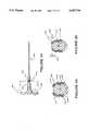
- an attached catheter hubcontains compressible, resilient sealing material such as a foam rubber which compresses to form a seal during hub collapse, the sealing material having an axial opening, similar to the sealing material disclosed in Shaffer, supra.
- a novel and improved blood withdrawal devicecomprising a housing which maintains sterility of a medical needle and other internal parts of the device until use and which automatically fully retracts the needle into the housing after use.
- a blood acquisition vacuum tubee.g. a Vacutainer® made by Becton Dickenson.
- the devicebe usable but once and the needle be safely enclosed when retracted.
- the devicebe made with as few injection molded parts as possible.
- the devicebe made from as few as three injection molded parts (and as few as three extruded parts).
- It is yet another primary object to provide a novel and improved IV catheter insertion apparatuscomprising a housing which maintains sterility of a medical needle, a catheter and other internal parts of the apparatus until use and which automatically fully retracts the needle into the housing after use.
- the apparatusbe usable but once and the needle be safely enclosed when retracted.
- the apparatusbe made from as few as three injection molded parts (and as few as three extruded parts).
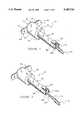
- FIG. 1is a perspective of a sealed blood withdrawal device, showing the outside of the device housing.
- FIG. 2is a perspective of the blood withdrawal device seen in FIG. 1 from which a needle cover and associated needle (not shown) have been pulled by first frangibly breaking away the needle cover from a portion of the housing.
- FIG. 3is a perspective of the blood withdrawal device seen in FIG. 2 showing a needle bared by cover removal and a partially removed seal which covered and protected the internal portion of a blood withdrawal vacuum tube barrel, relative to the needle.
- FIG. 4is a perspective of the blood withdrawal device showing displacement of a flap, seen in place in FIG. 3, the displacement permitting an area of the housing previously under the flap to be distorted, the distortion resulting in retraction of the needle into the housing.
- FIG. 5is a greatly magnified perspective of a medical needle having a portion of the needle treated with a mold release.
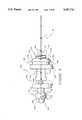
- FIG. 6is an exploded side view of a blood withdrawal device with some portions segmented and other portions removed for better presentation.
- FIG. 7is a lateral elevation of a needle/hub assembly which initially resides within the housing and is separably affixed to the cover.
- FIG. 8is a top elevation of the needle/hub assembly seen in FIG. 7.
- FIG. 9is a bottom elevation of the needle/hub assembly seen in FIG. 7.
- FIG. 10is an exploded perspective of a section of the needle/hub assembly seen in FIGS. 7-9 and a valve leaflet which is used to restrict regurgitant flow from the device.
- FIG. 10Ais a perspective of a section of a needle/hub assembly showing a valve leaflet affixed by molding to the needle/hub assembly through a living hinge.
- FIG. 11is an exploded view of the device of FIG. 6 with a first assembly step completed.
- FIG. 12is an exploded view of the device of FIG. 7 with a second assembly step, comprising attaching an elastic tube, completed.
- FIG. 13is an exploded view of the device of FIG. 7 with a third assembly step of attaching the elastic tube to the barrel part. (Note that a perspective of a completely assembled device is seen in FIG. 1.)
- FIG. 14is a section of a used device prior to retracting the needle.
- FIG. 14Ais a perspective of a needle/hub assembly with portions removed for clarity of presentation.
- FIG. 15is a lateral elevation of an elastic tube stretched between hubs of the barrel and needle/hub assembly parts.
- FIG. 16is a side elevation of an alternative embodiment of a needle/hub assembly showing a first part which is molded about and securely affixed to the needle and a second part which is molded about the needle but which is free to slide longitudinally along the needle.
- FIG. 17is a side elevation of the embodiment seen in FIG. 16 with the slidable part moved to an adjoining position relative to the first part.
- FIG. 18is a longitude section of a portion of the device showing the alternate needle/hub embodiment in three different positions in the device.
- FIG. 19is a section similar to the section seen in FIG. 18, but rotated 90°.
- FIG. 20is a perspective with some parts removed for clarity of a barrel section associated with the embodiment seen in FIGS. 16-20.
- FIG. 21is an exploded perspective of the device comprising the alternate needle/hub embodiment.
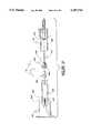
- FIG. 22is a perspective of an alternate embodiment of the invention showing a totally enclosed IV catheter insertion assembly.
- FIG. 23is a longitudinal section of the assembly seen in FIG. 22.
- FIG. 24is a side elevation of a catheter and needle with a compressible material section disposed proximal to the connector end of the catheter.
- FIG. 25is a section taken along lines 25--25 of FIG. 24, showing a section of the compressible material and an orifice therethrough.
- FIG. 26is a section similar to the section of FIG. 25 showing the material compressed and the orifice substantially closed thereby.
- proximalis used to indicate the segment of a device normally closest to the patient when it is being used.
- distalrefers to the other end.
- FIG. 1wherein an embodiment according to the invention of a blood withdrawal device 10 is seen.
- device 10comprises a barrel section 20 and a needle containment section 30.
- section 20is securely and hermetically sealed to section 30 along circular line 32.
- Barrel section 20comprises a planar seal 40 and a pair of left and right ear or handle parts, designated 50 and 60, respectively, and a hollow barrel 70.
- Planar seal 40is adhesively attached to barrel section 20 within a plane area defined by continuous line 72 such that the hollow of barrel 70 is maintained in a sterile condition prior to use.
- seal 40is manually removed.
- a different kind of sealmay be used, such as a snap-on part which may be molded as a tether-attached part of section 20. The snap-on part is not shown, but production of such parts is well known in the art. A more detailed description of the internal parts of barrel 70 is provided hereafter.
- Needle containment section 30comprises an elongated tube 80, a flap 90, a proximally facing front face plate 100 and a pull-ring 110.
- pull-ring 110is separable from front face plate 100 at a frangibly detachable segment 112, which is described in more detail hereafter.
- FIGS. 2-4Steps related to the use of device 10 are seen in FIGS. 2-4.
- pull-ring 110has been detached from front face plate 100. Detachment of segment 112 produces a ragged collar 114.
- a needle cover 120which is firmly affixed and integrally molded with pull-ring 110 appears through a hole created by removal of collar 114.
- a yoke 130snaps into place about the hole produced by removal of collar 114. Structure of yoke 130 and related parts are disclosed in more detail later.
- a next stepis to remove seal 40 from barrel section 20. Seal 40 is seen to be in process of being removed in FIG. 3.
- pull-ring and needle cover 120are removed from device 10.
- Needle cover 120is preferably attached to a hub 132 by a rotatably detachable coupler, such as by a threaded or bayonet type connector.
- the coupling attachment between hub 132 and cover 120must be able to support a pull force at least as great as a retarding force imposed in the opposite direction by a retracting mechanism which is energized by the pull extending cover 120 until engagement of yoke 130.
- a hollow medical needle 140is bared upon removal of cover 120.
- flap 90comprises a living hinge attachment 142 to elongated tube 80. Flap 90 also comprises a hook latch 144 which is normally engaged in a groove 146 proximally disposed in tube 80. Located flap 90, when disposed in groove 146 is a deformable area 148 of tube 80. While flap 90 is disposed and latched into groove 146, area 148 is fully protected from any deformation. Thus, during a medical blood withdrawal procedure, flap 90 is latched into groove 146. Once a blood acquisition procedure has been completed, flap 90 is rotated by action of a single digit after which needle 140 may be retracted by depressing area 148. Retraction places needle 140 safely inside tube 70.
- needle 140Only access inside tube 70 and needle 140 is a hole 150 in hub 132 which is the essentially the same diameter as the cross sectional diameter of needle 140. Further, as is explained later, needle 140 is securely held well away from hole 150. Retraction mechanisms for needle 140 are described in detail hereafter.
- cover 151is also seen in FIG. 4 .
- Cover 151is an alternative embodiment to seal 40.
- Cover 151has the advantage of not requiring a cover part to be made separately from barrel section 20.
- an additional sealsuch as a shrink wrap about exterior edges of cover 151 and related parts of handles 50 and 60 and tube 70 should be used. Making of parts attached by tether is well known in the art.
- FIG. 6wherein an exploded view of one embodiment of device 10 is seen to comprise needle containment section 30, a needle/hub part 160, a valve disk 170, an elastic tube 180 and barrel section 20. Attention is first drawn to needle/hub part 160 which is seen magnified for more clarity of details in FIGS. 7-9.
- Part 160comprises medical needle 140, a fore part 190 proximal to the sharp end of needle 140, a central part 192, and an aft part 194.
- Normally unseen extensions of needle 140 through part 160is indicated by double dashed lines 196 and 198 for clarity of extent of needle 140 passage through part 160.
- Fore part 190comprises yoke 130, hub 132, an annular groove 200, an annular stop 202 and an elbow shaped extension 204 which comprises an outwardly extending part 206.
- Central part 192comprises a frangible bridge 208 and a support 210.
- Aft part 194comprises a short shaft 212 and a tube hub 214.
- Part 160is preferably molded as a single part with end-to-end continuity between parts 190, 192 and 194.
- Aft part 160is firmly and securely affixed to needle 140 while fore part 190 is only slidably affixed and otherwise free to move along needle 140 when bridge 208 is franged.
- Hub 132comprises a releasable connector component which may be in the form of a threaded surface 216 as seen in FIGS. 7-9.
- Yoke 130comprises a sloped annular face 218 and a transverse latching surface ring 220 distal to and juxtaposing face 218.
- Groove 200is interposed between and contiguous with ring 220 and stop 202. Function and use of yoke 130, groove 200 and stop 202 are described in detail hereafter.
- extension 204protrudes distally from stop 202 via a lateral bar 222 to an elbow 224 where extension makes an orthogonal bend to provide upward and outwardly extending part 206.
- Bridge 208is a part which is narrow in both transverse dimensions to govern the degree of pressure required to frange bridge 208 from extending part 204.
- One of the surprising aspects of the instant inventionis the force which may be placed upon bridge 208 when pulling against a force retaining memory element used in retracting needle 140 without breaking bridge 208 away from extension 204.
- bridge 208might break.
- close tolerances maintained between needle 140 and fore part 190reduce and keep such torque to a level which does not cause bridge 208 to break.
- the method for achieving close tolerances between needle 140 and fore part 190is disclosed hereafter.
- Bridge 208is contiguous with support 210.
- Medially disposed about needle 140 and distally connected to support 210is shaft 212.
- Tube hub 214, connected to shaft 212provides a valve leaflet containment basket 226 wherein a one-way valve leaflet may be placed and trapped by a tube mounted on hub 214.
- Basket 226is better seen in FIG. 10. Basket 226 comprises a slot formed by a distal facing side 228 and a proximal facing side 230, the two sides being connected by a bottom plate 232 and two side members 234 and 236.
- Disk 240is made of compliant synthetic resinous material which, under pressure, deforms to seal end 238 of needle 140 against regurgitant flow when pressure downstream from needle 140 is greater than upstream pressure. This seal is very important to contain blood within needle 140 upon retraction of needle 140.
- disk 240comprises a plurality of raised feet which space the distal side of valve disk 240 away from side 230. That spacing and various cuts, designated 242, 244, 246 and 248 in distal end 250 of aft part 194 provide a low resistance pathway for effluent flow from a patient.
- disk 240is less than the sum of distances indicated by arrows B and C, but greater than B plus the diameter of needle end 238 to assure that regurgitant flow is always stopped, but disk 240 is not inadvertently held in an open condition by a tube stretched over hub 214.
- FIG. 10AAnother embodiment of a one-way valve is seen in FIG. 10A.
- hub 214is made of sufficiently resilient and compliant material
- a leaflet valvemay be integrally molded on the distal end of the hub.
- a thin planar wafer 252is integrally connected to a hub 214' (which is otherwise similar to hub 214) by a living hinge to curtail proximal flow through needle 140 at end 238 while being permissive to distal effluent flow.
- retractive forceis provided by a stretched tube.
- tube 180is cut to a predetermined length allowing for displacement about a proximal and a distal hub and for a length of the tube which stretches when device 10 is cocked as needle 140 is pulled outward for use.
- Tube 180comprises a proximal end 254 and a distal end 256.
- Tube 180may be made from any elastic material which is effectively inert to blood and which can provide a return force of at least four pounds when stretched. It is preferred that the tube be capable of being stretched at least a length of four times its resting length. However, the currently preferred material is latex. Note that a needle of one inch in length should require a tube not greater in length than about one-half inch.
- Barrel section 20comprises a plurality of internally disposed parts, generally designated 258.
- Parts 258comprise an elongated stabilizing key 260, a distal tube hub 262, an assembly plate 264, an rear delivery needle 266 and a needle cover 268.
- Stabilizing key 260is an elongated rod which stretches from assembly plate 264 to beyond stop 202 when device 10 is assembled and tube 180 is relaxed. Hub 262 is formed about needle 266 to provide a piercing entry to a low pressure collection tube (not shown) such as a Vacutainer®. As is standard practice in apparatus which is used to provide entry to low pressure collection tubes, a pierceable needle cover 268 is provided to deter leakage as collection tubes are replaced.
- FIGS. 6, 11, 12, 13 and 14demonstrate simplicity of assembly of device 10.
- FIG. 6is representative of parts in a preassembled configuration.
- Step one in assemblycomprises insertion of valve disk 170 into valve containment basket 226 as seen in FIG. 11. Note that step one is not required when a valve leaflet such as a valve formed by wafer 252 is an integral part of tube hub 214'.
- FIG. 12Attachment of tube 180 to hub 214 (or hub 214' in the case of the embodiment seen in FIG. 10A) is seen in FIG. 12.
- an adhesivebe applied to a proximal portion of hub 214 (or 214') immediately before tube 180 attachment.
- a suitable adhesive materialshould be used and care should be taken to assure that no inappropriate blood reactive material is allowed to contact areas where blood may flow.
- One adhesive which has provided satisfactory adhesion in models of the invention which have been reduced to practiceis Duro Super Glue, manufactured and distributed by Loctite Corporation, Cleveland, Ohio 44128, commonly known as Super Glue, although other adhesive materials known in the art may also be used within the scope of the invention.
- Tube 180is connected on distal end 256 to hub 262.
- stabilizing key 260is engaged in a locking slot 270 (See FIG. 14A) disposed in annular stop 202.
- Key 260is formed to slide laterally into and out of slot 270 and fit snugly therein when tube 180 is relaxed (i.e. during assembly). In this manner, no undue torque or rotational stress is placed upon frangible bridge 208 during assembly.
- a material relieving flat 272is formed along the plane of travel of key 260 in support 210.
- Needle cover 120comprises a female connecting segment 274 which is complementary to the male connector provided by hub 216. Cover 120 is preferably affixed by rotating section 30 relative to hub 216 although press-on connections which can withstand pull forces exerted by an elongating tube or spring or the like may also be used.
- tube 80 of section 30engages assembly plate 264.
- Tube 80is securely affixed to assembly plate 264 by adhesive or ultrasonic welding processes which are well known in the art of plastics assembly. In this manner, a hermetic seal is provided to protect needle 140.
- sections 20 and 30, in combinationprovide a housing for needle 140 which may be used without additional packaging for transport.
- Face plate 100comprises a proximal surface 276 and a distal surface 278. Disposed in surface 278 is an annular groove 280. Groove 280 completely encircles the area where cover 120 integrally connects to plate 100 and a ring hub 282 which is integral with the proximal end of cover 120. Hub 282 also integrally connects ring 110 to section 130. Groove 280 is of sufficient depth in plate 100 to permit facile frangible separation by a positive tug, twist or pull on ring 110 while retaining sufficient material to provide a hermetically sealed container and a sturdy and safe transport container. Products having such seals are available in commerce.
- annular hole 284is created in plate 100.
- the slanting annular surface 218 of yoke 130comprises a proximal diameter which is smaller than the diameter of hole 284 and a distal diameter which is larger than hole 284.
- the distal diameteris such that yoke 130 passes through hole 284 due to the "give" of material from which section 30 is made.
- Groove 200has a width which permits plate 100 to be engaged therein when yoke 130 is pulled through hole 284.
- the proximal face of stop 202has a diameter which is greater than hole 284 causing part 160 to be firmly affixed to plate 100 when yoke 130 passes through hole 284 as seen in FIG. 14.
- needle 140is automatically retracted.
- the retraction processinvolves (1) hingeably relocating protective flap 90 (as seen in FIG. 4) and (2) applying pressure upon part 206 through area 148 of tube 80 to frangibly separate fore part 190 from aft part 192 by breaking bridge 208 of needle/hub part 160.
- Flap 90is commonly released from attachment to tube 80 at groove 146 by inserting a thumb or finger under a portion of flap 90 and lifting.
- Bridge 208is broken by applying pressure, preferably between a thumb and forefinger, in the direction of arrows 284 and 286.
- Franging forcesi.e. shear forces
- substantially all other forces applied to bridge 208are those of tension caused by longitudinal stretching of tube 180.
- bridge 208comprises a geometric shape which is conducive to breaking when imposed upon by shear forces, but capable of withstanding large amounts of tension.
- needle/hub part 160is preferably molded as a unit about needle 140.
- Part 160is preferably injection molded.
- a thin coat of mold releaseis applied about needle 140 prior to molding.
- a coat 288 of mold releaseis firmly and securely affixed by the molding process causing needle 140 to be retracted when tube 140, attached to aft part 194, is permitted to contract.
- needle 140is retracted through yoke 130 and hub 132, the only access into tube 80 is through hole 150 which has substantially the same diameter as needle 140.
- needle 140is irretrievably held inside tube 80 by a relaxed tube 180.
- needle/hub part 160is made from a moldable material having sufficient tensile strength to withstand pull pressures of device 10 yet be facilely separated at bridge 208.
- part 160is preferably made of synthetic resinous material, such as polyurethane, polypropylene or polyethylene.
- synthetic resinous material usedwas polyurethane sold as Quik Cast distributed by TAP Plastics, Dublin, Calif. 94568, however many currently commercially available materials may be used within the scope of the invention.
- Barrel section 20is likewise preferably made from synthetic resinous material. Barrel section is also preferably molded about rear delivery needle 266. The same material which is used in currently commercially available barrels used with vacuum based blood drawing tubes (e.g. Vacutainer® tubes) may be used. Needle cover 268 may be the same as Vacutainer® barrel needle covers now in use.
- Needle containment section 30is preferably made by a single molded process. Mold material should be selected such that it provides sufficient material strength to engage and hold the hub 132 connection through the pull process, sufficiently flexible when made as a thin membrane to permit distortion sufficient to break bridge 208, and frangibility for facile opening as at groove 280.
- the materialis preferably a synthetic resinous material and may be polyethylene, although other materials meeting flexibility, medical compatibility and strength requirements may be used.
- a needle/hub assembly 300comprises two parts, designated fore part 302 and aft-part 304, which are formed about a needle 140. Parts 302 and 304 may be molded about needle 140 simultaneously. Part 302 is preferably molded about a segment of needle 140 to which a mold release has been applied, as earlier described. (See FIG. 5.)
- Fore part 302comprises a central body 306 and a pair of outwardly extending wings or arms, individually designated 308 and 310.
- Each arm 308 and 310is connected to central body 306 by a biased hinge 312 and 314, respectively.
- the biasing of hinges 312 and 314is preferably formed as a part of the molding process. Such hinges are well known in the art; as an example note hinges on telephone connectors.
- Each arm 308,310is biased to extend outwardly from central body 306 a predetermined distance.
- Disposed at the outer end 318,320 of each arm 308,310, respectively,is an inwardly projecting latching extremity 322,324.
- Central body 306comprises a cover connecting hub 132' which is similar in form and function to hub 132.
- a portion 316is disposed distal to hub 132' where hinges 312 and 314 are attached.
- Aft part 304comprises a central body part 326, a pair of outwardly extending and biased wings or arms 328 and 330 and a tube hub 332.
- Wing 330comprises an inwardly projecting strut 334 which ends at a clamping face 336.
- wing 328comprises an inwardly projecting jaw 338. Function and use of the various parts of fore part 302 and aft part 304 are disclosed in detail hereafter.
- fore part 302is preferably molded about needle 140, but not attached thereto, except by the natural engagement provided by materially surrounding the circumference of a portion of the needle. This permits fore part 302 to be rotated 90° and moved into linkable proximity with aft part 304 as seen in FIG. 17.
- This second embodimentcomprises a barrel section 20', tube 180, needle hub assembly 300 and needle containment section 30.
- Barrel section 20'is substantially the same as barrel section 20 except for the substitution of a guide-catch cylinder 340 integrally and medially disposed on a fore portion of barrel section 20' rather than stabilizing key similarly disposed upon barrel section 20.
- Guide-catch cylinder 340is best seen in FIG. 20.
- barrel 20'comprises barrel 70, a substantially closed fore face 342 of barrel 70, distal needle hub 262, providing access to needle 266, and guide-catch cylinder 340.
- Guide-catch cylinder 340is medially disposed upon face 342 and extends in elongated fashion in line with of needle 140 (not seen in FIG. 20).
- Hub 262is medially disposed inside cylinder 340 along the same line.
- Cylinder 340comprises a plurality of slots which provide relief for outwardly biased members of parts 302 and 304, travel guide for assembly 300 and catch stops which selectively maintain parts of assembly 300 in a proximal position while needle 140 is in use.
- a first slot 346disposed to act as a guide, extends the length of cylinder 340. In this embodiment device 10 is assembled to dispose a portion of wing 330 in slot 346.
- cylinder 340Disposed at its distal end, cylinder 340 comprises a second slot 348 offset at 90° from slot 346 and having a length which is adequate for relief from compression of wing 308 when assembly 300 is distally disposed before use. Likewise, cylinder 340 comprises a third slot 350 similar to slot 348 and juxtaposed 180°, therefrom, to provide relief from compression of wing 310. A fourth slot 352 of cylinder 340 is distally disposed 180° from slot 346 and provides before-use relief from compression for wing 328. Should an outwardly biasing material be used in manufacturing assembly 300 which does not take a set after time between assembly and use, it is not necessary to provide slots 348, 350 and 352.
- Cylinder 340provides openings for four slots at its proximal end 353, i.e. slots 346, 354, 356 and 358.
- slot 346provides a guide for assembly 300 by containment of wing 330.
- Longitudinally slots 354 and 356are respectively aligned with slots 348 and 350.
- Slot 354comprises a catching edge 360 for end 318 of wing 308 while slot 356 comprises a catching edge 362 for end 320 of wing 310.
- Slot 358is aligned with slot 352 and provides a catching edge 364 for wing 328 as is described in detail hereafter.
- Each slothas a depth such that in combination latch portions of wings 308, 310 and 328 occur substantially simultaneously.
- FIGS. 18 and 19Latching operation of elements of assembly 300 is best seen in FIGS. 18 and 19.
- FIGS. 18 and 19are divided by dashed lines into three sections (A, B and C) to demonstrate operation of fore part 302 and aft part 304 of assembly 300 at different positions along the length of cylinder 340.
- wings 328 and 330are vertically disposed in FIG. 18.
- Wings 308 and 310are vertically oriented in FIG. 19 as parts of assembly 300 in FIG. 19 are rotated by 90° relative to parts in FIG. 18.
- wing 328extends superiorly from central body part 326 along a line 366 to pivot arcuately upward at arc 368 to join a superior line 370. Further, line 370 ends at a latch point 372. From latch point 372, the shape of wing 328 is further defined by an inwardly progressing line 374 and an acutely connected line 376 which, in combination, demarcate jaw 338.
- wing 330is free to move in the longitudinal direction of needle 140 guided by slot 346.
- wing 328is disposed in an uncompressed or relaxed state within slot 352.
- assembly 300passes through an intermediate state seen in FIG. 18B.
- the form of wing 328 formed along arcuate line 368permits wing 328 to be collapsed such that line 370 of wing 328 coincides with the cylindrical inner surface of cylinder 340. In this manner, the aft part 304 of assembly 300 is facilely allowed to move through cylinder 340.
- FIG. 19device 10 has been rotated 90° clockwise relative to a view of the needle 140 end of the device.
- wings 308 and 310are vertically oriented. Each arm 308,310 resides in a non-compressed state in slots 348 and 350, respectively.
- Arm 308comprises an arcuate surface 378, similar to the wing 328 arcuate surface along line 368, which provides a facile release from slot 348.
- Arm 310comprises a similar surface 380 for facile release from slot 350.
- arms 308 and 310are compressed inwardly.
- Each arm 308 and 310comprises a latching foot, respectively designated 382 and 384, which engages and grips a distal annular surface 386 of central body 326.
- fore part 302is releasibly adjoined to aft part 304 while assembly 300 is pulled forward to a cocked position.
- arms 308 and 310are outwardly biased into slots 354 and 356, respectively.
- feet 382 and 384catch against edges 360 and 362 to form a permanent latch thereby.
- outward biasing of arms 308 and 310release the grasp of feet 382 and 384 against surface 386, thereby releasing the grip of aft part 304 by fore part 302.
- aft part 304When the grip of aft part 304 is so released, needle 140 is relieved of proximal containment in tube 80 when aft part 304 is triggered to a released state to be distally displaced by contraction of tube 180.
- aft partis released from a cocked state by depressing area 148 in the direction of arrow 388. Such depression forces wing 328 inward until the part of wing 328 along line 374 and latch point 372 clears edge 364. Contraction of elastic tube 180 retracts aft part 304 and needle 140, to which the aft part is securely affixed, into the distal section of tube 80 seen in FIG. 18A.
- Fore part 302remains proximal in tube 80 to effectively plug the hole formed by removal of hub 282 and collar 114.
- fore part 302comprises a threaded hub 132', similar to hub 132.
- FIG. 21an exploded view of parts which are comprised in the alternate embodiment seen in FIGS. 16-20 is seen.
- the alternate embodiment partscomprise barrel section 20', tube 180, needle hub assembly 300 and needle containment section 30.
- section 30Affixing section 30 to section 20', preferably by application of adhesives or by ultrasonic welding to form a hermetically sealed package about needle 140.
- apparatus 400is seen to comprise a pull ring 110' affixed to and integral with a front face plate 100', which is similar to face plate 100.
- Face plate 100'is integral with a tube 80' which is also similar in form and function to tube 80.
- Face plate 100'also comprises an annular frangible segment 112' which permits ring 110' and a collar portion 114' of plate 100' to be frangibly separated from plate 100' when pulling a needle assembly proximally from tube 80' for use.
- Tube 80'comprises a flap 90' which, similar in form and function to flap 90, is releasibly affixed to a groove 146' and on an opposite end attached by a living hinge 142' to tube 80'.
- Tube 80'is elongated to fully contain a needle 140' used in catheter insertion and a needle withdrawal mechanism 402, as seen in FIG. 23.
- tube 80'At its distal end, tube 80' comprises an annular raised section 404 which acts as a handle during the needle pulling procedure.
- Further apparatus 400comprises a distal plate 406 which is securely affixed at the distal end 408 of tube 80' to enclose and hermetically seal needle 140' and withdrawal mechanism 402 inside tube 80'.
- Withdrawal mechanism 402comprises a needle/hub part 160' which is similar to part 160 in form and function. Basic ways in which part 160' departs from the form of part 160 is found at the proximal and distal segments of part 160'. Proximally, part 160' comprises a secondary connection 412 for a transcutaneous catheter 410.
- part 160'comprises a connection 414 whereby a return energy storing component 416 is affixed to a hub 418 portion of part 160'.
- part 160'comprises catheter needle 140', a fore part 190' proximal to the sharp end of needle 140', a central part 192', and an aft part 194'.
- parts 190', 192' and 194'are substantially the same in form and function to parts 190, 192 and 194.
- a bridge part 208' and upwardly extending part 206'each being respectively similar in form and function to bridge 208 and part 206, are similarly inwardly disposed for compressible access via a depressible area 148' of tube 80'.
- Component 416comprises a plurality of piston head parts 420, 422 and 424 which communicate with an inner wall 426 of tube 80' to effectively pull and retain a vacuum as the mechanism is moved proximally.
- the vacuum contained in tube 80'provides the force which retracts needle 140' when bridge 208' is frangibly broken.
- parts 420, 422 and 424must create a differential force of at least four pounds to overcome forces of stiction in both the needle and other retracting mechanisms.
- a minimum atmospheric pressure of ten pounds per square inchis assumed.
- each part 420, 422 and 424must have a minimum area of four tenths of a square inch. As parts 420, 422 and 424 are essentially circular planes, their diameter must be a minimum of 0.36 inches (0.9 centimeters).
- Parts 420, 422 and 424are securely affixed to a medially disposed piston hub 428 which is in turn likewise affixed to mechanism 416 via aft part 194'.
- needle 140'communicates with hub 428 via part 194.
- Hub 428is a hollow vessel which is completely sealed, except for a gas communicating plug 432 disposed proximal from part 424.
- Plug 432is made from a hydrophobic material which is permissive to passage of gas (air), but retards flow of water based liquids (such as blood).
- the preferred materialis Goretex, a material available from W. L. Gore Company, Arizona, USA.
- Plug 432is securely affixed to hub 428 to provide a pathway for gas to relieve pressure as blood is communicated into hub 428 through needle 140'.
- Hub 428is made from either translucent or transparent materials through which blood may be seen. Thus, by providing the pathway from needle 140' into hub 428 and permitting air to escape from hub 428 as influent blood arrives, hub 428 provides a visually determinable blood "flash" which is commonly used to ascertain entry of needle 140' into a blood vessel.
- ring 110' and collar 114'are frangibly separated from plate 100'.
- Needle cover 120', needle 140' and catheter 410are pulled from tube 80' until mechanism 402 is firmly attached to plate 100'. By this action a vacuum is created in the portion of tube 80' which is distal to part 420.
- Cover 120'is removed and needle 140' and catheter 410 are transcutaneously inserted into a patient following good medical practices.
- needle 140'enters a blood vessel, blood is communicated to hub 428 through which a blood "flash" communicates to the attending technician that the vessel has been entered.
- flap 90'is lifted to provide access to area 148'.
- a portion of area 148'is depressed to frangibly break bridge 208' which releases the aft portion 194' of mechanism 402 to be retracted by force stored via parts 420, 422 and 424 in cooperation with tube 80'. Needle 140' is thereby withdrawn. Note that the only pathway through which blood may be communicated upon withdrawal of needle 140' is into tube 80'. This limitation upon needle withdrawal is a definite advantage over non-selfretracting needle systems currently in use. Under appropriately controlled conditions, catheter 410 is removed for attachment to other medical devices.
- FIG. 24Another catheter embodiment is seen in FIG. 24 wherein a catheter 410' has a connecting end 500 which comprises a fore section 502, a medial section 504 and an aft section 506.
- Aft section 506comprises connecting parts which are separable as earlier described secondary connection 412 is separable.
- Fore section 502securely affixes catheter 410' to the rest of connecting end 500.
- Section 504is medially interposed between sections 502 and 506 and is normally adhesively affixed thereto. Such adhesives are well known in the art.
- section 504comprises a tubular member 508 which has a central orifice 510 provided as a fluid pathway.
- An outside ring section 512partially encircles member 508.
- Disposed within section 512are a pair of rigid supports 514 and 516.
- Each support 514 and 516comprises a radially extending inward bend 518 and 520, respectively.
- Supports 514 and 516 with bends 518 and 520are disposed to constrict orifice 510 when squeeze pressure is applied in the direction of arrows 522 and 524, seen in FIG. 26. In this manner orifice 510 may be closed to prevent escape of blood through catheter 410' when changing connections to the catheter after it has been inserted into a vessel of a patient.
Landscapes
- Health & Medical Sciences (AREA)
- Life Sciences & Earth Sciences (AREA)
- Engineering & Computer Science (AREA)
- General Health & Medical Sciences (AREA)
- Public Health (AREA)
- Biomedical Technology (AREA)
- Heart & Thoracic Surgery (AREA)
- Hematology (AREA)
- Animal Behavior & Ethology (AREA)
- Veterinary Medicine (AREA)
- Biophysics (AREA)
- Medical Informatics (AREA)
- Physics & Mathematics (AREA)
- Pathology (AREA)
- Molecular Biology (AREA)
- Surgery (AREA)
- Anesthesiology (AREA)
- Manufacturing & Machinery (AREA)
- Vascular Medicine (AREA)
- Environmental & Geological Engineering (AREA)
- Diabetes (AREA)
- Pulmonology (AREA)
- Infusion, Injection, And Reservoir Apparatuses (AREA)
Abstract
Description
Claims (11)
Priority Applications (20)
| Application Number | Priority Date | Filing Date | Title |
|---|---|---|---|
| US08/436,976US5487734A (en) | 1995-01-10 | 1995-05-08 | Self retracting catheter needle apparatus and methods |
| US08/484,533US5542927A (en) | 1995-01-10 | 1995-06-07 | Self retracting syringe needle apparatus and methods |
| US08/565,881US5616135A (en) | 1995-01-10 | 1995-12-01 | Self retracting medical needle apparatus and methods |
| ES95944713TES2194932T3 (en) | 1995-01-10 | 1995-12-21 | EQUIPMENT FOR SELF-TREATMENT MEDICAL NEEDLES. |
| EP95944713AEP0801579B1 (en) | 1995-01-10 | 1995-12-21 | Self-retracting medical needle apparatus |
| PCT/US1995/016665WO1996021483A1 (en) | 1995-01-10 | 1995-12-21 | Self-retracting medical needle apparatus and methods |
| AU48537/96AAU704966B2 (en) | 1995-01-10 | 1995-12-21 | Self-retracting medical needle apparatus and methods |
| MX9704120AMX9704120A (en) | 1995-01-10 | 1995-12-21 | Self-retracting medical needle apparatus and methods. |
| CA002205831ACA2205831A1 (en) | 1995-01-10 | 1995-12-21 | Self-retracting medical needle apparatus and methods |
| CNB951972812ACN1170600C (en) | 1995-01-10 | 1995-12-21 | Device and method for self-retracting needle |
| BR9510270ABR9510270A (en) | 1995-01-10 | 1995-12-21 | Apparatus for carrying and using and then removing a medical needle to carry a sharp-pointed medical needle and for inserting a catheter self-retracting latch catheter insertion needle set and latch release device for an auto-needle withdrawal system retractable medical syringe system medical needle device combination of connection and processes to use a self retracting needle device to use a device that safely retracts a medical needle to use a needle retraction device to use and discard medical needle to use a blood withdrawing needle to retract and to withdraw a medical needle into a container to use and dispose of a medical needle to use a blood withdrawing needle to mount a self-retracting needle apparatus for safe needle transport to produce a disposable blood collection device and to insert a catheter into a patient |
| NZ302476ANZ302476A (en) | 1995-01-10 | 1995-12-21 | Self-retracting medical needle apparatus and methods |
| DE69530005TDE69530005T2 (en) | 1995-01-10 | 1995-12-21 | MEDICAL DEVICE WITH AUTOMATICALLY RETRACTABLE NEEDLE |
| JP52167696AJP3768533B2 (en) | 1995-01-10 | 1995-12-21 | Automatic collection medical needle device |
| US08/595,802US5656031A (en) | 1995-01-10 | 1996-02-02 | Medical syringe and self retracting needle apparatus |
| US08/744,108US5836917A (en) | 1995-01-10 | 1996-11-05 | Self retracting medical needle apparatus and methods |
| US08/882,644US6024727A (en) | 1995-01-10 | 1997-06-25 | Self-retracting medical needle apparatus and methods |
| US08/927,053US5823997A (en) | 1995-01-10 | 1997-09-10 | Medical needle safety apparatus and methods |
| US09/105,078US5928200A (en) | 1995-01-10 | 1998-06-25 | Self retracting medical needle apparatus and methods |
| US09/118,624US5980488A (en) | 1995-01-10 | 1998-07-17 | Medical needle safety apparatus and methods |
Applications Claiming Priority (2)
| Application Number | Priority Date | Filing Date | Title |
|---|---|---|---|
| US08/370,728US5480385A (en) | 1995-01-10 | 1995-01-10 | Self retracting medical needle apparatus and methods |
| US08/436,976US5487734A (en) | 1995-01-10 | 1995-05-08 | Self retracting catheter needle apparatus and methods |
Related Parent Applications (2)
| Application Number | Title | Priority Date | Filing Date |
|---|---|---|---|
| US08/370,728Continuation-In-PartUS5480385A (en) | 1995-01-10 | 1995-01-10 | Self retracting medical needle apparatus and methods |
| US08/484,533Continuation-In-PartUS5542927A (en) | 1995-01-10 | 1995-06-07 | Self retracting syringe needle apparatus and methods |
Related Child Applications (7)
| Application Number | Title | Priority Date | Filing Date |
|---|---|---|---|
| US08/370,728Continuation-In-PartUS5480385A (en) | 1995-01-10 | 1995-01-10 | Self retracting medical needle apparatus and methods |
| US08/455,514ContinuationUS5549708A (en) | 1995-01-10 | 1995-05-31 | Self retracting medical needle apparatus and methods |
| US08/484,533Continuation-In-PartUS5542927A (en) | 1995-01-10 | 1995-06-07 | Self retracting syringe needle apparatus and methods |
| US08/565,881ContinuationUS5616135A (en) | 1995-01-10 | 1995-12-01 | Self retracting medical needle apparatus and methods |
| US08/744,108Continuation-In-PartUS5836917A (en) | 1995-01-10 | 1996-11-05 | Self retracting medical needle apparatus and methods |
| US08/927,053Continuation-In-PartUS5823997A (en) | 1995-01-10 | 1997-09-10 | Medical needle safety apparatus and methods |
| US09/118,624ContinuationUS5980488A (en) | 1995-01-10 | 1998-07-17 | Medical needle safety apparatus and methods |
Publications (1)
| Publication Number | Publication Date |
|---|---|
| US5487734Atrue US5487734A (en) | 1996-01-30 |
Family
ID=46249669
Family Applications (1)
| Application Number | Title | Priority Date | Filing Date |
|---|---|---|---|
| US08/436,976Expired - LifetimeUS5487734A (en) | 1995-01-10 | 1995-05-08 | Self retracting catheter needle apparatus and methods |
Country Status (1)
| Country | Link |
|---|---|
| US (1) | US5487734A (en) |
Cited By (94)
| Publication number | Priority date | Publication date | Assignee | Title |
|---|---|---|---|---|
| US5800395A (en)* | 1996-12-05 | 1998-09-01 | Mdc Investment Holdings, Inc. | Medical device with retractable needle |
| US5823997A (en)* | 1995-01-10 | 1998-10-20 | Specialized Health Products, Inc. | Medical needle safety apparatus and methods |
| US5830190A (en)* | 1996-06-11 | 1998-11-03 | Becton Dickinson And Company | Protected needle catheter placement device having needle placement visualization features and method for its use |
| WO1999044660A1 (en)* | 1998-02-05 | 1999-09-10 | Mdc Investment Holdings, Inc. | Fluid sampling device with retractable needle |
| US5957892A (en)* | 1998-03-12 | 1999-09-28 | Specialized Health Products, Inc. | Safety catheter insertion apparatus and methods |
| US6036675A (en)* | 1999-02-03 | 2000-03-14 | Specialized Health Products, Inc. | Safety sterile cartride unit apparatus and methods |
| WO2000018465A1 (en) | 1998-09-30 | 2000-04-06 | Becton, Dickinson And Company | Needle retraction mechanism with consistent retraction speed |
| WO2000018466A1 (en)* | 1998-09-30 | 2000-04-06 | Becton Dickinson And Company | Needle retraction mechanism with controlled retraction speed |
| WO2000020058A1 (en)* | 1998-10-06 | 2000-04-13 | Dean Brian Prestidge | A needle apparatus |
| US6063040A (en)* | 1998-01-16 | 2000-05-16 | Specialized Health Products, Inc. | Self retracting needle apparatus and method for phlebotomy |
| US6086563A (en)* | 1999-01-13 | 2000-07-11 | Becton, Dickinson And Company | Needle retraction mechanism with push start retraction |
| US6096005A (en)* | 1989-07-11 | 2000-08-01 | Mdc Investment Holdings, Inc. | Retractable needle medical devices |
| EP0942760A4 (en)* | 1996-12-05 | 2000-10-18 | Mdc Invest Holdings Inc | Fluid collection device with retractable needle |
| US6152901A (en)* | 1998-07-03 | 2000-11-28 | Altair | Blood sampling device with vacuum tube |
| US6224576B1 (en) | 1999-11-04 | 2001-05-01 | Specialized Health Products, Inc. | Safety device for a needle having two sharpened ends |
| US20010039401A1 (en)* | 1999-11-04 | 2001-11-08 | Safety Syringe Corporation | Safety shield for medical needles |
| AU752790B2 (en)* | 1998-10-06 | 2002-10-03 | Dean Brian Prestidge | A needle apparatus |
| US20020193748A1 (en)* | 1999-11-18 | 2002-12-19 | Cocker Robin Craig | Safety device |
| US6544235B2 (en) | 2001-05-03 | 2003-04-08 | Steven A. Motisi | Valve for use with a catheter |
| US6592556B1 (en) | 2000-07-19 | 2003-07-15 | Tyco Healthcare Group Lp | Medical needle safety apparatus and methods |
| US20030191438A1 (en)* | 2002-04-05 | 2003-10-09 | Ferguson F. Mark | Safety shield for medical needles |
| US20030199827A1 (en)* | 2000-04-28 | 2003-10-23 | Thorne David L. | Passively activated safety shield for a catheter insertion needle |
| US6641555B1 (en) | 1997-11-12 | 2003-11-04 | Mdc Investment Holdings, Inc. | Fluid collection device with captured retractable needle |
| US20040044318A1 (en)* | 2001-03-02 | 2004-03-04 | Fiser Richard L | Passive safety shield |
| US20040078025A1 (en)* | 1998-12-15 | 2004-04-22 | Botich Michael J. | Fluid collection device with captured retractable needle |
| US20040092879A1 (en)* | 2000-11-06 | 2004-05-13 | Medamicus, Inc. | Safety introducer apparatus and method therefor |
| US6796968B2 (en) | 1999-11-04 | 2004-09-28 | Tyco Healthcare Group Lp | Reaccessible medical needle safety devices and methods |
| US20040193112A1 (en)* | 2003-03-26 | 2004-09-30 | Medamicus, Inc. | Safety introducer assembly and method |
| WO2005011792A1 (en)* | 2003-07-31 | 2005-02-10 | Medigard Limited | Cannula/catheter introducer with retractable needle |
| US20050049553A1 (en)* | 2003-08-27 | 2005-03-03 | Triplett Daniel J. | Safety needle with positive flush |
| US20050059933A1 (en)* | 2002-12-27 | 2005-03-17 | Johnson Carolyn M. | Safety intravenous (IV) catheter assembly |
| US20050080397A1 (en)* | 2003-10-14 | 2005-04-14 | Altman Sanford D. | Safety dialysis needle/catheter system and method of use |
| US7029461B2 (en) | 1999-11-04 | 2006-04-18 | Tyco Healthcare Group Lp | Safety shield for medical needles |
| US7056306B1 (en) | 1998-02-05 | 2006-06-06 | Mdc Investment Holdings, Inc. | Fluid sampling device with retractable needle |
| US7144389B2 (en) | 2001-03-14 | 2006-12-05 | Tyco Healthcare Group, Lp | Safety shield for medical needles |
| US20070008132A1 (en)* | 2004-12-23 | 2007-01-11 | Bellantoni John V | Switchable directional coupler for use with RF devices |
| US20070016139A1 (en)* | 2005-07-11 | 2007-01-18 | Sherwood Services Ag | Needle safety shield with reset |
| US20070118081A1 (en)* | 2003-09-17 | 2007-05-24 | Dali Medical Devices Ltd. | Automatic needle device |
| US20070239117A1 (en)* | 2006-03-21 | 2007-10-11 | Chelak Todd M | Passive latch ring safety shield for injection devices |
| US7300423B2 (en) | 2003-02-14 | 2007-11-27 | Tyco Healthcare Group Lp | Safety device with trigger mechanism |
| US20070276216A1 (en)* | 2004-08-16 | 2007-11-29 | Refael Beyar | Image-Guided Navigation for Catheter-Based Interventions |
| US20080051724A1 (en)* | 2003-02-14 | 2008-02-28 | Bedford Anthony J | Safety device with trigger mechanism |
| US20080269693A1 (en)* | 2007-04-26 | 2008-10-30 | Tyco Healthcare Group Lp | Multifunctional medical access device |
| US20090118639A1 (en)* | 2007-11-01 | 2009-05-07 | Tyco Healthcare Group Lp | Active Stylet Safety Shield |
| US20090131955A1 (en)* | 2005-09-29 | 2009-05-21 | Corindus Ltd. | Methods and apparatuses for treatment of hollow organs |
| US20090221958A1 (en)* | 2005-05-10 | 2009-09-03 | Rafael Beyar | User interface for remote control catheterization |
| WO2009137410A1 (en)* | 2008-05-06 | 2009-11-12 | Corindus Ltd. | Catheter system |
| US7654735B2 (en) | 2005-11-03 | 2010-02-02 | Covidien Ag | Electronic thermometer |
| US7731692B2 (en) | 2005-07-11 | 2010-06-08 | Covidien Ag | Device for shielding a sharp tip of a cannula and method of using the same |
| US7828773B2 (en) | 2005-07-11 | 2010-11-09 | Covidien Ag | Safety reset key and needle assembly |
| US20110040281A1 (en)* | 2009-08-14 | 2011-02-17 | White Steven B | Integrated vascular delivery system |
| US7905857B2 (en) | 2005-07-11 | 2011-03-15 | Covidien Ag | Needle assembly including obturator with safety reset |
| US7951115B2 (en) | 2003-10-14 | 2011-05-31 | Altman Sanford D | Safety dialysis needle/catheter system and method of use |
| US20110144658A1 (en)* | 2008-08-29 | 2011-06-16 | Corindus Inc. | Catheter simulation and assistance system |
| US20110152882A1 (en)* | 2008-08-29 | 2011-06-23 | Corindus Inc. | Catheter control system and graphical user interface |
| US7985216B2 (en) | 2004-03-16 | 2011-07-26 | Dali Medical Devices Ltd. | Medicinal container engagement and automatic needle device |
| US20110238082A1 (en)* | 2008-12-12 | 2011-09-29 | Corindus Inc. | Remote catheter procedure system |
| US8172809B2 (en) | 1999-11-04 | 2012-05-08 | Tyco Healthcare Group Lp | Safety shield apparatus and mounting structure for use with medical needle devices |
| US8177760B2 (en) | 2004-05-12 | 2012-05-15 | C. R. Bard, Inc. | Valved connector |
| US8376998B2 (en) | 2003-09-17 | 2013-02-19 | Elcam Medical Agricultural Cooperative Association Ltd. | Automatic injection device |
| US20130178759A1 (en)* | 2012-01-10 | 2013-07-11 | Becton, Dickinson And Company | Low Cost Blood Collection Set Using Blister Package |
| US8771230B2 (en) | 2010-05-19 | 2014-07-08 | Tangent Medical Technologies, Llc | Integrated vascular delivery system |
| US8790297B2 (en) | 2009-03-18 | 2014-07-29 | Corindus, Inc. | Remote catheter system with steerable catheter |
| US8814833B2 (en) | 2010-05-19 | 2014-08-26 | Tangent Medical Technologies Llc | Safety needle system operable with a medical device |
| US8834417B2 (en) | 2005-06-06 | 2014-09-16 | Covidien Ag | Needle assembly with removable depth stop |
| US9220568B2 (en) | 2009-10-12 | 2015-12-29 | Corindus Inc. | Catheter system with percutaneous device movement algorithm |
| WO2016037127A1 (en)* | 2014-09-05 | 2016-03-10 | C.R. Bard, Inc. | Catheter insertion device including retractable needle |
| US9522254B2 (en) | 2013-01-30 | 2016-12-20 | Vascular Pathways, Inc. | Systems and methods for venipuncture and catheter placement |
| US9616201B2 (en) | 2011-01-31 | 2017-04-11 | Vascular Pathways, Inc. | Intravenous catheter and insertion device with reduced blood spatter |
| US9675784B2 (en) | 2007-04-18 | 2017-06-13 | Vascular Pathways, Inc. | Intravenous catheter insertion and blood sample devices and method of use |
| US9833293B2 (en) | 2010-09-17 | 2017-12-05 | Corindus, Inc. | Robotic catheter system |
| US9861792B2 (en) | 2011-02-25 | 2018-01-09 | C. R. Bard, Inc. | Medical component insertion device including a retractable needle |
| US9872971B2 (en) | 2010-05-14 | 2018-01-23 | C. R. Bard, Inc. | Guidewire extension system for a catheter placement device |
| US9950139B2 (en) | 2010-05-14 | 2018-04-24 | C. R. Bard, Inc. | Catheter placement device including guidewire and catheter control elements |
| US9962229B2 (en) | 2009-10-12 | 2018-05-08 | Corindus, Inc. | System and method for navigating a guide wire |
| US10086170B2 (en) | 2014-02-04 | 2018-10-02 | Icu Medical, Inc. | Self-priming systems and methods |
| US10220191B2 (en) | 2005-07-06 | 2019-03-05 | Vascular Pathways, Inc. | Intravenous catheter insertion device and method of use |
| US10384039B2 (en) | 2010-05-14 | 2019-08-20 | C. R. Bard, Inc. | Catheter insertion device including top-mounted advancement components |
| US10426931B2 (en) | 2010-05-14 | 2019-10-01 | C. R. Bard, Inc. | Catheter placement device and method |
| US10493262B2 (en) | 2016-09-12 | 2019-12-03 | C. R. Bard, Inc. | Blood control for a catheter insertion device |
| US10773018B2 (en) | 2015-06-25 | 2020-09-15 | Sol-Millennium Medical Hk Limited | Safety mechanism for a retaining needle and a retaining needle having the safety mechanism |
| USD903101S1 (en) | 2011-05-13 | 2020-11-24 | C. R. Bard, Inc. | Catheter |
| USD903100S1 (en) | 2015-05-01 | 2020-11-24 | C. R. Bard, Inc. | Catheter placement device |
| USD921884S1 (en) | 2018-07-27 | 2021-06-08 | Bard Access Systems, Inc. | Catheter insertion device |
| US11040176B2 (en) | 2015-05-15 | 2021-06-22 | C. R. Bard, Inc. | Catheter placement device including an extensible needle safety component |
| US11058825B2 (en) | 2015-11-27 | 2021-07-13 | Sanofi-Aventis Deutschland Gmbh | Cap for an injection device |
| US11213632B2 (en) | 2017-03-24 | 2022-01-04 | Sol-Millennium Medical Hk Limited | Safety syringe and safety mechanism for use in the same |
| CN114053557A (en)* | 2020-08-03 | 2022-02-18 | 巴德阿克塞斯系统股份有限公司 | Detachable needle and dilator catheter placement device and related methods |
| US11389626B2 (en) | 2018-03-07 | 2022-07-19 | Bard Access Systems, Inc. | Guidewire advancement and blood flashback systems for a medical device insertion system |
| US11400260B2 (en) | 2017-03-01 | 2022-08-02 | C. R. Bard, Inc. | Catheter insertion device |
| US11559665B2 (en) | 2019-08-19 | 2023-01-24 | Becton, Dickinson And Company | Midline catheter placement device |
| US11918314B2 (en) | 2009-10-12 | 2024-03-05 | Corindus, Inc. | System and method for navigating a guide wire |
| US11925779B2 (en) | 2010-05-14 | 2024-03-12 | C. R. Bard, Inc. | Catheter insertion device including top-mounted advancement components |
| US12440652B2 (en) | 2019-09-20 | 2025-10-14 | Bard Peripheral Vascular, Inc. | Intravenous catheter-placement device and method thereof |
Citations (32)
| Publication number | Priority date | Publication date | Assignee | Title |
|---|---|---|---|---|
| US4676783A (en)* | 1985-09-03 | 1987-06-30 | The University Of Virginia Alumni Patents Foundation | Retractable safety needle |
| US4813936A (en)* | 1988-01-20 | 1989-03-21 | Geralyn M. Schroeder | Retracting hypodermic needle |
| US4850374A (en)* | 1987-09-24 | 1989-07-25 | Commonwealth Of Puerto Rico | Blood sampler with retractable needle |
| US4892525A (en)* | 1984-01-18 | 1990-01-09 | Synertex | Hypodermic needle protective barrel and cap packaging |
| US4900311A (en)* | 1988-12-06 | 1990-02-13 | Lawrence Stern | Hypodermic syringe |
| US4909794A (en)* | 1988-06-24 | 1990-03-20 | Habley Medical Technology Corporation | Combination retractable needle cannula and cannula lock for a medication carpule |
| US4946446A (en)* | 1989-06-14 | 1990-08-07 | Vadher Dinesh L | Retractable needle |
| US4955870A (en)* | 1988-08-23 | 1990-09-11 | Ridderheim Kristen A | Hypodermic syringe with retractable needle |
| US4966593A (en)* | 1989-03-06 | 1990-10-30 | Design Specialties Laboratories | Disposable hypodermic syringe with retractable needle |
| US4978340A (en)* | 1988-06-15 | 1990-12-18 | Alteron Incorporated | Syringe with retractable needle |
| US4985021A (en)* | 1989-01-31 | 1991-01-15 | Jeff Straw | Safety enclosure system for medical devices |
| US4986816A (en)* | 1989-01-18 | 1991-01-22 | On-Gard Systems, Inc. | Needle unsheathing, resheathing and handling apparatus |
| US4988339A (en)* | 1988-12-30 | 1991-01-29 | Vadher Dinesh L | Retractable needle/syringe devices for blood collection, catheterization, and medicinal injection procedures |
| US4994034A (en)* | 1989-07-11 | 1991-02-19 | Botich Michael J | Retractable needle hypodermic syringe system |
| US4995870A (en)* | 1990-05-09 | 1991-02-26 | Baskas Morris J | Disposable syringe with retractable needle |
| US5061251A (en)* | 1990-06-12 | 1991-10-29 | Juhasz Paul R | Syringe device |
| US5092853A (en)* | 1991-02-04 | 1992-03-03 | Couvertier Ii Douglas | Automatic retractable medical needle and method |
| US5098402A (en)* | 1990-05-23 | 1992-03-24 | Davis Lynn E | Retractable hypodermic syringe |
| US5114404A (en)* | 1990-07-24 | 1992-05-19 | Paxton Gerald R | Multifunctional retractable needle type general purpose disabling syringe having enhanced safety features and related method of operation |
| US5147303A (en)* | 1991-05-23 | 1992-09-15 | Martin Bret C | Disposable safety syringe |
| US5180370A (en)* | 1992-05-18 | 1993-01-19 | Gillespie Elgene R | Safety hypodermic syringe with retractable needle |
| US5188599A (en)* | 1989-07-11 | 1993-02-23 | Med-Design, Inc. | Retractable needle system |
| US5195983A (en)* | 1991-08-27 | 1993-03-23 | Penta Associates | Syringe guard and disposal system |
| US5195985A (en)* | 1990-05-25 | 1993-03-23 | Hall John E | Syringe having a retractable needle |
| US5205824A (en)* | 1991-06-13 | 1993-04-27 | Mazur Matthew S | Retractable syringe with a closed barrel |
| US5205823A (en)* | 1990-10-04 | 1993-04-27 | Retrax, Inc. | Retractable syringe |
| US5215533A (en)* | 1989-09-18 | 1993-06-01 | Robb Pascal Patent Pty. Ltd. | Safety syringe incorporating vacuum retraction of the needle |
| US5246428A (en)* | 1992-07-30 | 1993-09-21 | Falknor Donald W | Needle safety mechanism |
| US5246427A (en)* | 1992-11-25 | 1993-09-21 | Sturman Martin F | Safety hypodermic needle and shielding cap assembly |
| US5254099A (en)* | 1992-03-10 | 1993-10-19 | Injectimed. Inc. | Hard cover for pre-cocking protected injection apparatus |
| US5256153A (en)* | 1989-03-02 | 1993-10-26 | Hake Lawrence W | Hypodermic needle guard and method to prevent needle stick injuries |
| US5267976A (en)* | 1990-03-08 | 1993-12-07 | Blue Star Corporation S.A. | Syringe with self-retracting needle |
- 1995
- 1995-05-08USUS08/436,976patent/US5487734A/ennot_activeExpired - Lifetime
Patent Citations (32)
| Publication number | Priority date | Publication date | Assignee | Title |
|---|---|---|---|---|
| US4892525A (en)* | 1984-01-18 | 1990-01-09 | Synertex | Hypodermic needle protective barrel and cap packaging |
| US4676783A (en)* | 1985-09-03 | 1987-06-30 | The University Of Virginia Alumni Patents Foundation | Retractable safety needle |
| US4850374A (en)* | 1987-09-24 | 1989-07-25 | Commonwealth Of Puerto Rico | Blood sampler with retractable needle |
| US4813936A (en)* | 1988-01-20 | 1989-03-21 | Geralyn M. Schroeder | Retracting hypodermic needle |
| US4978340A (en)* | 1988-06-15 | 1990-12-18 | Alteron Incorporated | Syringe with retractable needle |
| US4909794A (en)* | 1988-06-24 | 1990-03-20 | Habley Medical Technology Corporation | Combination retractable needle cannula and cannula lock for a medication carpule |
| US4955870A (en)* | 1988-08-23 | 1990-09-11 | Ridderheim Kristen A | Hypodermic syringe with retractable needle |
| US4900311A (en)* | 1988-12-06 | 1990-02-13 | Lawrence Stern | Hypodermic syringe |
| US4988339A (en)* | 1988-12-30 | 1991-01-29 | Vadher Dinesh L | Retractable needle/syringe devices for blood collection, catheterization, and medicinal injection procedures |
| US4986816A (en)* | 1989-01-18 | 1991-01-22 | On-Gard Systems, Inc. | Needle unsheathing, resheathing and handling apparatus |
| US4985021A (en)* | 1989-01-31 | 1991-01-15 | Jeff Straw | Safety enclosure system for medical devices |
| US5256153A (en)* | 1989-03-02 | 1993-10-26 | Hake Lawrence W | Hypodermic needle guard and method to prevent needle stick injuries |
| US4966593A (en)* | 1989-03-06 | 1990-10-30 | Design Specialties Laboratories | Disposable hypodermic syringe with retractable needle |
| US4946446A (en)* | 1989-06-14 | 1990-08-07 | Vadher Dinesh L | Retractable needle |
| US4994034A (en)* | 1989-07-11 | 1991-02-19 | Botich Michael J | Retractable needle hypodermic syringe system |
| US5188599A (en)* | 1989-07-11 | 1993-02-23 | Med-Design, Inc. | Retractable needle system |
| US5215533A (en)* | 1989-09-18 | 1993-06-01 | Robb Pascal Patent Pty. Ltd. | Safety syringe incorporating vacuum retraction of the needle |
| US5267976A (en)* | 1990-03-08 | 1993-12-07 | Blue Star Corporation S.A. | Syringe with self-retracting needle |
| US4995870A (en)* | 1990-05-09 | 1991-02-26 | Baskas Morris J | Disposable syringe with retractable needle |
| US5098402A (en)* | 1990-05-23 | 1992-03-24 | Davis Lynn E | Retractable hypodermic syringe |
| US5195985A (en)* | 1990-05-25 | 1993-03-23 | Hall John E | Syringe having a retractable needle |
| US5061251A (en)* | 1990-06-12 | 1991-10-29 | Juhasz Paul R | Syringe device |
| US5114404A (en)* | 1990-07-24 | 1992-05-19 | Paxton Gerald R | Multifunctional retractable needle type general purpose disabling syringe having enhanced safety features and related method of operation |
| US5205823A (en)* | 1990-10-04 | 1993-04-27 | Retrax, Inc. | Retractable syringe |
| US5092853A (en)* | 1991-02-04 | 1992-03-03 | Couvertier Ii Douglas | Automatic retractable medical needle and method |
| US5147303A (en)* | 1991-05-23 | 1992-09-15 | Martin Bret C | Disposable safety syringe |
| US5205824A (en)* | 1991-06-13 | 1993-04-27 | Mazur Matthew S | Retractable syringe with a closed barrel |
| US5195983A (en)* | 1991-08-27 | 1993-03-23 | Penta Associates | Syringe guard and disposal system |
| US5254099A (en)* | 1992-03-10 | 1993-10-19 | Injectimed. Inc. | Hard cover for pre-cocking protected injection apparatus |
| US5180370A (en)* | 1992-05-18 | 1993-01-19 | Gillespie Elgene R | Safety hypodermic syringe with retractable needle |
| US5246428A (en)* | 1992-07-30 | 1993-09-21 | Falknor Donald W | Needle safety mechanism |
| US5246427A (en)* | 1992-11-25 | 1993-09-21 | Sturman Martin F | Safety hypodermic needle and shielding cap assembly |
Non-Patent Citations (2)
| Title |
|---|
| Patricia Seremet, "Small Tolland Company Takes Jab at Safety Needle Market," The Hartford Courant, Sep. 13, 1994, pp. F1 and F3. |
| Patricia Seremet, Small Tolland Company Takes Jab at Safety Needle Market, The Hartford Courant , Sep. 13, 1994, pp. F1 and F3.* |
Cited By (215)
| Publication number | Priority date | Publication date | Assignee | Title |
|---|---|---|---|---|
| US6096005A (en)* | 1989-07-11 | 2000-08-01 | Mdc Investment Holdings, Inc. | Retractable needle medical devices |
| US5823997A (en)* | 1995-01-10 | 1998-10-20 | Specialized Health Products, Inc. | Medical needle safety apparatus and methods |
| US5980488A (en)* | 1995-01-10 | 1999-11-09 | Specialized Health Products, Inc. | Medical needle safety apparatus and methods |
| US5830190A (en)* | 1996-06-11 | 1998-11-03 | Becton Dickinson And Company | Protected needle catheter placement device having needle placement visualization features and method for its use |
| US6436070B1 (en) | 1996-12-05 | 2002-08-20 | Mdc Investment Holdings, Inc. | Catheter insertion device with retractable needle |
| EP0942760A4 (en)* | 1996-12-05 | 2000-10-18 | Mdc Invest Holdings Inc | Fluid collection device with retractable needle |
| US5800395A (en)* | 1996-12-05 | 1998-09-01 | Mdc Investment Holdings, Inc. | Medical device with retractable needle |
| US8308685B2 (en) | 1997-11-12 | 2012-11-13 | Mdc Investment Holdings, Inc. | Fluid collection device with captured retractable needle |
| US20040092872A1 (en)* | 1997-11-12 | 2004-05-13 | Botich Michael J. | Fluid collection device with captured retractable needle |
| US20100191146A1 (en)* | 1997-11-12 | 2010-07-29 | Mdc Investment Holdings, Inc. | Fluid collection device with captured retractable needle |
| US6641555B1 (en) | 1997-11-12 | 2003-11-04 | Mdc Investment Holdings, Inc. | Fluid collection device with captured retractable needle |
| US7691083B2 (en) | 1997-11-12 | 2010-04-06 | MDC Investmant Holdings, Inc. | Fluid collection device with captured retractable needle |
| US6063040A (en)* | 1998-01-16 | 2000-05-16 | Specialized Health Products, Inc. | Self retracting needle apparatus and method for phlebotomy |
| US7056306B1 (en) | 1998-02-05 | 2006-06-06 | Mdc Investment Holdings, Inc. | Fluid sampling device with retractable needle |
| AU736394B2 (en)* | 1998-02-05 | 2001-07-26 | Mdc Investment Holdings, Inc. | Fluid sampling device with retractable needle |
| WO1999044660A1 (en)* | 1998-02-05 | 1999-09-10 | Mdc Investment Holdings, Inc. | Fluid sampling device with retractable needle |
| US5957892A (en)* | 1998-03-12 | 1999-09-28 | Specialized Health Products, Inc. | Safety catheter insertion apparatus and methods |
| US6152901A (en)* | 1998-07-03 | 2000-11-28 | Altair | Blood sampling device with vacuum tube |
| US6210375B1 (en) | 1998-09-30 | 2001-04-03 | Becton, Dickinson And Company | Needle retraction mechanism with controlled retraction speed |
| WO2000018466A1 (en)* | 1998-09-30 | 2000-04-06 | Becton Dickinson And Company | Needle retraction mechanism with controlled retraction speed |
| WO2000018465A1 (en) | 1998-09-30 | 2000-04-06 | Becton, Dickinson And Company | Needle retraction mechanism with consistent retraction speed |
| WO2000020058A1 (en)* | 1998-10-06 | 2000-04-13 | Dean Brian Prestidge | A needle apparatus |
| AU752790B2 (en)* | 1998-10-06 | 2002-10-03 | Dean Brian Prestidge | A needle apparatus |
| US7097633B2 (en) | 1998-12-15 | 2006-08-29 | Mdc Investment Holdings, Inc. | Fluid collection device with captured retractable needle |
| US20040078025A1 (en)* | 1998-12-15 | 2004-04-22 | Botich Michael J. | Fluid collection device with captured retractable needle |
| US6086563A (en)* | 1999-01-13 | 2000-07-11 | Becton, Dickinson And Company | Needle retraction mechanism with push start retraction |
| WO2000041760A1 (en) | 1999-01-13 | 2000-07-20 | Becton, Dickinson And Company | Needle retraction mechanism with push start retraction |
| US6036675A (en)* | 1999-02-03 | 2000-03-14 | Specialized Health Products, Inc. | Safety sterile cartride unit apparatus and methods |
| US6796968B2 (en) | 1999-11-04 | 2004-09-28 | Tyco Healthcare Group Lp | Reaccessible medical needle safety devices and methods |
| US20040193120A1 (en)* | 1999-11-04 | 2004-09-30 | Ferguson F. Mark | Safety shield for blood collection medical needles |
| US8172809B2 (en) | 1999-11-04 | 2012-05-08 | Tyco Healthcare Group Lp | Safety shield apparatus and mounting structure for use with medical needle devices |
| US6949086B2 (en) | 1999-11-04 | 2005-09-27 | Tyco Healthcare Group Lp | Seldinger safety shield for medical needles |
| US20010039401A1 (en)* | 1999-11-04 | 2001-11-08 | Safety Syringe Corporation | Safety shield for medical needles |
| US6224576B1 (en) | 1999-11-04 | 2001-05-01 | Specialized Health Products, Inc. | Safety device for a needle having two sharpened ends |
| US8226617B2 (en) | 1999-11-04 | 2012-07-24 | Tyco Healthcare Group Lp | Safety shield apparatus and mounting structure for use with medical needle devices |
| US7862547B2 (en) | 1999-11-04 | 2011-01-04 | Tyco Healthcare Group Lp | Safety shield for medical needles |
| US20030229317A1 (en)* | 1999-11-04 | 2003-12-11 | Ferguson F. Mark | Seldinger safety shield for medical needles |
| US20060129106A1 (en)* | 1999-11-04 | 2006-06-15 | Ferguson F M | Safety shield for medical needles |
| US7198618B2 (en) | 1999-11-04 | 2007-04-03 | Tyco Healthcare Group Lp | Safety shield for medical needles |
| US7029461B2 (en) | 1999-11-04 | 2006-04-18 | Tyco Healthcare Group Lp | Safety shield for medical needles |
| US7320682B2 (en) | 1999-11-18 | 2008-01-22 | Tyco Healthcare Group Lp | Safety device |
| US20020193748A1 (en)* | 1999-11-18 | 2002-12-19 | Cocker Robin Craig | Safety device |
| US20030199827A1 (en)* | 2000-04-28 | 2003-10-23 | Thorne David L. | Passively activated safety shield for a catheter insertion needle |
| US6972002B2 (en) | 2000-04-28 | 2005-12-06 | Specialized Health Products, Inc. | Passively activated safety shield for a catheter insertion needle |
| US6592556B1 (en) | 2000-07-19 | 2003-07-15 | Tyco Healthcare Group Lp | Medical needle safety apparatus and methods |
| US20040092879A1 (en)* | 2000-11-06 | 2004-05-13 | Medamicus, Inc. | Safety introducer apparatus and method therefor |
| US20040049159A1 (en)* | 2000-12-08 | 2004-03-11 | Barrus Roy L. | Safety shield for medical needles |
| US7438703B2 (en) | 2000-12-08 | 2008-10-21 | Tyco Healthcare Group Lp | Safety shield for medical needles |
| US20050059936A1 (en)* | 2001-03-02 | 2005-03-17 | Fiser Richard L. | Passive safety shield |
| US20040044318A1 (en)* | 2001-03-02 | 2004-03-04 | Fiser Richard L | Passive safety shield |
| US7361159B2 (en) | 2001-03-02 | 2008-04-22 | Covidien Ag | Passive safety shield |
| US7144389B2 (en) | 2001-03-14 | 2006-12-05 | Tyco Healthcare Group, Lp | Safety shield for medical needles |
| US6544235B2 (en) | 2001-05-03 | 2003-04-08 | Steven A. Motisi | Valve for use with a catheter |
| US7001363B2 (en) | 2002-04-05 | 2006-02-21 | F. Mark Ferguson | Safety shield for medical needles |
| US20030191438A1 (en)* | 2002-04-05 | 2003-10-09 | Ferguson F. Mark | Safety shield for medical needles |
| US20050059933A1 (en)* | 2002-12-27 | 2005-03-17 | Johnson Carolyn M. | Safety intravenous (IV) catheter assembly |
| US7553296B2 (en) | 2003-02-14 | 2009-06-30 | Tyco Healthcare Group Lp | Safety device with trigger mechanism |
| US20080051724A1 (en)* | 2003-02-14 | 2008-02-28 | Bedford Anthony J | Safety device with trigger mechanism |
| US7300423B2 (en) | 2003-02-14 | 2007-11-27 | Tyco Healthcare Group Lp | Safety device with trigger mechanism |
| US20040193112A1 (en)* | 2003-03-26 | 2004-09-30 | Medamicus, Inc. | Safety introducer assembly and method |
| US7001396B2 (en) | 2003-03-26 | 2006-02-21 | Enpath Medical, Inc. | Safety introducer assembly and method |
| WO2005011792A1 (en)* | 2003-07-31 | 2005-02-10 | Medigard Limited | Cannula/catheter introducer with retractable needle |
| US20070073237A1 (en)* | 2003-07-31 | 2007-03-29 | Aaron Rodd | Cannula/catheter introducer |
| US7762992B2 (en) | 2003-08-27 | 2010-07-27 | C. R. Bard, Inc. | Safety needle with positive flush |
| US9101747B2 (en) | 2003-08-27 | 2015-08-11 | C. R. Bard, Inc. | Safety needle with positive flush |
| US8038666B2 (en) | 2003-08-27 | 2011-10-18 | C.R. Bard, Inc. | Safety needle with positive flush |
| US7097637B2 (en) | 2003-08-27 | 2006-08-29 | C. R. Bard, Inc. | Safety needle with positive flush |
| US20060271013A1 (en)* | 2003-08-27 | 2006-11-30 | Triplett Daniel J | Safety needle with positive flush |
| US20100286656A1 (en)* | 2003-08-27 | 2010-11-11 | C. R. Bard, Inc. | Safety needle with positive flush |
| US8491527B2 (en) | 2003-08-27 | 2013-07-23 | C. R. Bard, Inc. | Safety needle with positive flush |
| US7569044B2 (en) | 2003-08-27 | 2009-08-04 | C. R. Bard, Inc. | Safety needle with positive flush |
| US20050049553A1 (en)* | 2003-08-27 | 2005-03-03 | Triplett Daniel J. | Safety needle with positive flush |
| US8808247B2 (en) | 2003-08-27 | 2014-08-19 | C. R. Bard, Inc. | Safety needle with positive flush |
| US20070118081A1 (en)* | 2003-09-17 | 2007-05-24 | Dali Medical Devices Ltd. | Automatic needle device |
| EP2650033A2 (en) | 2003-09-17 | 2013-10-16 | Elcam Medical Agricultural Cooperative Association Ltd. | Automatic injection device |
| US11623051B2 (en) | 2003-09-17 | 2023-04-11 | E3D Agricultural Cooperative Association Ltd. | Automatic injection device |
| US8376998B2 (en) | 2003-09-17 | 2013-02-19 | Elcam Medical Agricultural Cooperative Association Ltd. | Automatic injection device |
| US20050080397A1 (en)* | 2003-10-14 | 2005-04-14 | Altman Sanford D. | Safety dialysis needle/catheter system and method of use |
| US7951115B2 (en) | 2003-10-14 | 2011-05-31 | Altman Sanford D | Safety dialysis needle/catheter system and method of use |
| US7335187B2 (en) | 2003-10-14 | 2008-02-26 | Sda Product, Inc. | Safety dialysis needle/catheter system and method of use |
| US7985216B2 (en) | 2004-03-16 | 2011-07-26 | Dali Medical Devices Ltd. | Medicinal container engagement and automatic needle device |
| US8177760B2 (en) | 2004-05-12 | 2012-05-15 | C. R. Bard, Inc. | Valved connector |
| US8600477B2 (en) | 2004-08-16 | 2013-12-03 | Corinduc, Inc. | Image-guided navigation for catheter-based interventions |
| US20070276216A1 (en)* | 2004-08-16 | 2007-11-29 | Refael Beyar | Image-Guided Navigation for Catheter-Based Interventions |
| US20070008132A1 (en)* | 2004-12-23 | 2007-01-11 | Bellantoni John V | Switchable directional coupler for use with RF devices |
| US20090221958A1 (en)* | 2005-05-10 | 2009-09-03 | Rafael Beyar | User interface for remote control catheterization |
| US8257302B2 (en) | 2005-05-10 | 2012-09-04 | Corindus, Inc. | User interface for remote control catheterization |
| US8834417B2 (en) | 2005-06-06 | 2014-09-16 | Covidien Ag | Needle assembly with removable depth stop |
| US11925778B2 (en) | 2005-07-06 | 2024-03-12 | Vascular Pathways, Inc. | Intravenous catheter insertion device |
| US12370349B2 (en) | 2005-07-06 | 2025-07-29 | Vascular Pathways, Inc. | Intravenous catheter insertion device and method of use |
| US11020571B2 (en) | 2005-07-06 | 2021-06-01 | Vascular Pathways, Inc. | Intravenous catheter insertion device and method of use |
| US11577054B2 (en) | 2005-07-06 | 2023-02-14 | Vascular Pathways, Inc. | Intravenous catheter insertion device and method of use |
| US10220191B2 (en) | 2005-07-06 | 2019-03-05 | Vascular Pathways, Inc. | Intravenous catheter insertion device and method of use |
| US10912930B2 (en) | 2005-07-06 | 2021-02-09 | Vascular Pathways, Inc. | Intravenous catheter insertion device and method of use |
| US10806906B2 (en) | 2005-07-06 | 2020-10-20 | Vascular Pathways, Inc. | Intravenous catheter insertion device and method of use |
| US8348894B2 (en) | 2005-07-11 | 2013-01-08 | Covidien Lp | Needle assembly including obturator with safety reset |
| US8419687B2 (en) | 2005-07-11 | 2013-04-16 | Covidien Ag | Device for shielding a sharp tip of a cannula and method of using the same |
| US7731692B2 (en) | 2005-07-11 | 2010-06-08 | Covidien Ag | Device for shielding a sharp tip of a cannula and method of using the same |
| US7976498B2 (en) | 2005-07-11 | 2011-07-12 | Tyco Healthcare Group Lp | Needle assembly including obturator with safety reset |
| US8162889B2 (en) | 2005-07-11 | 2012-04-24 | Covidien Ag | Safety reset key and needle assembly |
| US20100217152A1 (en)* | 2005-07-11 | 2010-08-26 | Covidien Ag | Device for Shielding a Sharp Tip of a Cannula and Method of Using the Same |
| US8523809B2 (en) | 2005-07-11 | 2013-09-03 | Covidien Ag | Device for shielding a sharp tip of a cannula and method of using the same |
| US7905857B2 (en) | 2005-07-11 | 2011-03-15 | Covidien Ag | Needle assembly including obturator with safety reset |
| US20100217153A1 (en)* | 2005-07-11 | 2010-08-26 | Covidien Ag | Device for Shielding a Sharp Tip of a Cannula and Method of Using the Same |
| US7850650B2 (en) | 2005-07-11 | 2010-12-14 | Covidien Ag | Needle safety shield with reset |
| US20070016139A1 (en)* | 2005-07-11 | 2007-01-18 | Sherwood Services Ag | Needle safety shield with reset |
| US7828773B2 (en) | 2005-07-11 | 2010-11-09 | Covidien Ag | Safety reset key and needle assembly |
| US20090131955A1 (en)* | 2005-09-29 | 2009-05-21 | Corindus Ltd. | Methods and apparatuses for treatment of hollow organs |
| US7654735B2 (en) | 2005-11-03 | 2010-02-02 | Covidien Ag | Electronic thermometer |
| US8496627B2 (en) | 2006-03-21 | 2013-07-30 | Covidien Lp | Passive latch ring safety shield for injection devices |
| US20070239117A1 (en)* | 2006-03-21 | 2007-10-11 | Chelak Todd M | Passive latch ring safety shield for injection devices |
| US9757540B2 (en) | 2007-04-18 | 2017-09-12 | Vascular Pathways, Inc. | Intravenous catheter insertion and blood sample devices and method of use |
| US9675784B2 (en) | 2007-04-18 | 2017-06-13 | Vascular Pathways, Inc. | Intravenous catheter insertion and blood sample devices and method of use |
| US20080269693A1 (en)* | 2007-04-26 | 2008-10-30 | Tyco Healthcare Group Lp | Multifunctional medical access device |
| US10086171B2 (en) | 2007-05-07 | 2018-10-02 | Vascular Pathways, Inc. | Intravenous catheter insertion and blood sample devices and method of use |
| US10799680B2 (en) | 2007-05-07 | 2020-10-13 | Vascular Pathways, Inc. | Intravenous catheter insertion and blood sample devices and method of use |
| US10525236B2 (en) | 2007-05-07 | 2020-01-07 | Vascular Pathways, Inc. | Intravenous catheter insertion and blood sample devices and method of use |
| US20090118639A1 (en)* | 2007-11-01 | 2009-05-07 | Tyco Healthcare Group Lp | Active Stylet Safety Shield |
| US8357104B2 (en) | 2007-11-01 | 2013-01-22 | Coviden Lp | Active stylet safety shield |
| USD680645S1 (en) | 2008-05-06 | 2013-04-23 | Corindus Inc. | Catheter system cassette |
| US8480618B2 (en) | 2008-05-06 | 2013-07-09 | Corindus Inc. | Catheter system |
| US20100069833A1 (en)* | 2008-05-06 | 2010-03-18 | Corindus Ltd. | Catheter system |
| US8828021B2 (en) | 2008-05-06 | 2014-09-09 | Corindus, Inc. | Catheter system |
| US20100076308A1 (en)* | 2008-05-06 | 2010-03-25 | Corindus Ltd. | Catheter system |
| US9095681B2 (en) | 2008-05-06 | 2015-08-04 | Corindus Inc. | Catheter system |
| US20100076309A1 (en)* | 2008-05-06 | 2010-03-25 | Corindus Ltd. | Catheter system |
| US9168356B2 (en) | 2008-05-06 | 2015-10-27 | Corindus Inc. | Robotic catheter system |
| US10987491B2 (en) | 2008-05-06 | 2021-04-27 | Corindus, Inc. | Robotic catheter system |
| US7887549B2 (en) | 2008-05-06 | 2011-02-15 | Corindus Inc. | Catheter system |
| JP2011519678A (en)* | 2008-05-06 | 2011-07-14 | コリンダス インコーポレイテッド | Catheter system |
| US9402977B2 (en) | 2008-05-06 | 2016-08-02 | Corindus Inc. | Catheter system |
| US11717645B2 (en) | 2008-05-06 | 2023-08-08 | Corindus, Inc. | Robotic catheter system |
| WO2009137410A1 (en)* | 2008-05-06 | 2009-11-12 | Corindus Ltd. | Catheter system |
| US10342953B2 (en) | 2008-05-06 | 2019-07-09 | Corindus, Inc. | Robotic catheter system |
| US20100076310A1 (en)* | 2008-05-06 | 2010-03-25 | Corindus Ltd. | Catheter system |
| US9623209B2 (en) | 2008-05-06 | 2017-04-18 | Corindus, Inc. | Robotic catheter system |
| US20110152882A1 (en)* | 2008-08-29 | 2011-06-23 | Corindus Inc. | Catheter control system and graphical user interface |
| US8694157B2 (en) | 2008-08-29 | 2014-04-08 | Corindus, Inc. | Catheter control system and graphical user interface |
| US20110144658A1 (en)* | 2008-08-29 | 2011-06-16 | Corindus Inc. | Catheter simulation and assistance system |
| US9545497B2 (en) | 2008-12-12 | 2017-01-17 | Corindus, Inc. | Remote catheter procedure system |
| US10561821B2 (en) | 2008-12-12 | 2020-02-18 | Corindus, Inc. | Remote catheter procedure system |
| US20110238082A1 (en)* | 2008-12-12 | 2011-09-29 | Corindus Inc. | Remote catheter procedure system |
| US12171955B2 (en) | 2008-12-12 | 2024-12-24 | Siemens Healthineers Endovascular Robotics Inc | Remote catheter procedure system |
| US8790297B2 (en) | 2009-03-18 | 2014-07-29 | Corindus, Inc. | Remote catheter system with steerable catheter |
| US12370348B2 (en) | 2009-08-14 | 2025-07-29 | The Regents Of The University Of Michigan | Integrated vascular delivery system |
| US20110040281A1 (en)* | 2009-08-14 | 2011-02-17 | White Steven B | Integrated vascular delivery system |
| US9962526B2 (en) | 2009-08-14 | 2018-05-08 | The Regents Of The University Of Michigan | Integrated vascular delivery system |
| US11577053B2 (en) | 2009-08-14 | 2023-02-14 | The Regents Of The University Of Michigan | Integrated vascular delivery system |
| US10668252B2 (en) | 2009-08-14 | 2020-06-02 | The Regents Of The University Of Michigan | Integrated vascular delivery system |
| US9592366B2 (en) | 2009-08-14 | 2017-03-14 | The Regents Of The University Of Michigan | Integrated vascular delivery system |
| US9962229B2 (en) | 2009-10-12 | 2018-05-08 | Corindus, Inc. | System and method for navigating a guide wire |
| US10881474B2 (en) | 2009-10-12 | 2021-01-05 | Corindus, Inc. | System and method for navigating a guide wire |
| US11696808B2 (en) | 2009-10-12 | 2023-07-11 | Corindus, Inc. | System and method for navigating a guide wire |
| US11918314B2 (en) | 2009-10-12 | 2024-03-05 | Corindus, Inc. | System and method for navigating a guide wire |
| US9220568B2 (en) | 2009-10-12 | 2015-12-29 | Corindus Inc. | Catheter system with percutaneous device movement algorithm |
| US10426931B2 (en) | 2010-05-14 | 2019-10-01 | C. R. Bard, Inc. | Catheter placement device and method |
| US11000678B2 (en) | 2010-05-14 | 2021-05-11 | C. R. Bard, Inc. | Catheter placement device and method |
| US12296115B2 (en) | 2010-05-14 | 2025-05-13 | C. R. Bard, Inc. | Insertion device |
| US10384039B2 (en) | 2010-05-14 | 2019-08-20 | C. R. Bard, Inc. | Catheter insertion device including top-mounted advancement components |
| US9872971B2 (en) | 2010-05-14 | 2018-01-23 | C. R. Bard, Inc. | Guidewire extension system for a catheter placement device |
| US11135406B2 (en) | 2010-05-14 | 2021-10-05 | C. R. Bard, Inc. | Catheter insertion device including top-mounted advancement components |
| US10688281B2 (en) | 2010-05-14 | 2020-06-23 | C. R. Bard, Inc. | Catheter placement device including guidewire and catheter control elements |
| US10688280B2 (en) | 2010-05-14 | 2020-06-23 | C. R. Bard, Inc. | Catheter placement device including guidewire and catheter control elements |
| US10722685B2 (en) | 2010-05-14 | 2020-07-28 | C. R. Bard, Inc. | Catheter placement device including guidewire and catheter control elements |
| US9950139B2 (en) | 2010-05-14 | 2018-04-24 | C. R. Bard, Inc. | Catheter placement device including guidewire and catheter control elements |
| US11925779B2 (en) | 2010-05-14 | 2024-03-12 | C. R. Bard, Inc. | Catheter insertion device including top-mounted advancement components |
| US11278702B2 (en) | 2010-05-14 | 2022-03-22 | C. R. Bard, Inc. | Guidewire extension system for a catheter placement device |
| US9308354B2 (en) | 2010-05-19 | 2016-04-12 | Tangent Medical Technologies Llc | Safety needle system operable with a medical device |
| US9827398B2 (en) | 2010-05-19 | 2017-11-28 | Tangent Medical Technologies, Inc. | Integrated vascular delivery system |
| US12059538B2 (en) | 2010-05-19 | 2024-08-13 | Tangent Medical Technologies, Inc. | Safety needle system operable with a medical device |
| US10159818B2 (en) | 2010-05-19 | 2018-12-25 | Tangent Medical Technologies, Inc. | Safety needle system operable with a medical device |
| US10905858B2 (en) | 2010-05-19 | 2021-02-02 | Tangent Medical Technologies, Inc. | Safety needle system operable with a medical device |
| US8814833B2 (en) | 2010-05-19 | 2014-08-26 | Tangent Medical Technologies Llc | Safety needle system operable with a medical device |
| US10569057B2 (en) | 2010-05-19 | 2020-02-25 | Tangent Medical Technologies, Inc. | Integrated vascular delivery system |
| US11577052B2 (en) | 2010-05-19 | 2023-02-14 | Tangent Medical Technologies, Inc. | Integrated vascular delivery system |
| US8771230B2 (en) | 2010-05-19 | 2014-07-08 | Tangent Medical Technologies, Llc | Integrated vascular delivery system |
| US9833293B2 (en) | 2010-09-17 | 2017-12-05 | Corindus, Inc. | Robotic catheter system |
| US10328239B2 (en) | 2011-01-31 | 2019-06-25 | Vascular Pathways, Inc. | Intravenous catheter and insertion device with reduced blood spatter |
| US11202886B2 (en) | 2011-01-31 | 2021-12-21 | Vascular Pathways, Inc. | Intravenous catheter and insertion device with reduced blood spatter |
| US9616201B2 (en) | 2011-01-31 | 2017-04-11 | Vascular Pathways, Inc. | Intravenous catheter and insertion device with reduced blood spatter |
| US11123524B2 (en) | 2011-02-25 | 2021-09-21 | C. R. Bard, Inc. | Medical component insertion device including a retractable needle |
| US9861792B2 (en) | 2011-02-25 | 2018-01-09 | C. R. Bard, Inc. | Medical component insertion device including a retractable needle |
| US11931534B2 (en) | 2011-02-25 | 2024-03-19 | C. R. Bard, Inc. | Medical component insertion device including a retractable needle |
| USD903101S1 (en) | 2011-05-13 | 2020-11-24 | C. R. Bard, Inc. | Catheter |
| US20130178759A1 (en)* | 2012-01-10 | 2013-07-11 | Becton, Dickinson And Company | Low Cost Blood Collection Set Using Blister Package |
| US10398361B2 (en)* | 2012-01-10 | 2019-09-03 | Becton, Dickinson And Company | Low cost blood collection set using blister package |
| US9522254B2 (en) | 2013-01-30 | 2016-12-20 | Vascular Pathways, Inc. | Systems and methods for venipuncture and catheter placement |
| US10265507B2 (en) | 2013-01-30 | 2019-04-23 | Vascular Pathways, Inc. | Systems and methods for venipuncture and catheter placement |
| US11724071B2 (en) | 2014-02-04 | 2023-08-15 | Icu Medical, Inc. | Self-priming systems and methods |
| US10086170B2 (en) | 2014-02-04 | 2018-10-02 | Icu Medical, Inc. | Self-priming systems and methods |
| US10814107B2 (en) | 2014-02-04 | 2020-10-27 | Icu Medical, Inc. | Self-priming systems and methods |
| US11565089B2 (en) | 2014-09-05 | 2023-01-31 | C. R. Bard, Inc. | Catheter insertion device including retractable needle |
| US11033719B2 (en) | 2014-09-05 | 2021-06-15 | C. R. Bard, Inc. | Catheter insertion device including retractable needle |
| US10232146B2 (en) | 2014-09-05 | 2019-03-19 | C. R. Bard, Inc. | Catheter insertion device including retractable needle |
| WO2016037127A1 (en)* | 2014-09-05 | 2016-03-10 | C.R. Bard, Inc. | Catheter insertion device including retractable needle |
| USD1069106S1 (en) | 2015-05-01 | 2025-04-01 | C. R. Bard, Inc. | Catheter placement device |
| USD903100S1 (en) | 2015-05-01 | 2020-11-24 | C. R. Bard, Inc. | Catheter placement device |
| US12161819B2 (en) | 2015-05-15 | 2024-12-10 | C. R. Bard, Inc. | Catheter placement device including an extensible needle safety component |
| US11040176B2 (en) | 2015-05-15 | 2021-06-22 | C. R. Bard, Inc. | Catheter placement device including an extensible needle safety component |
| US10773018B2 (en) | 2015-06-25 | 2020-09-15 | Sol-Millennium Medical Hk Limited | Safety mechanism for a retaining needle and a retaining needle having the safety mechanism |
| US11058825B2 (en) | 2015-11-27 | 2021-07-13 | Sanofi-Aventis Deutschland Gmbh | Cap for an injection device |
| US11904151B2 (en) | 2015-11-27 | 2024-02-20 | Sanofi-Aventis Deutschland Gmbh | Cap for an injection device |
| US11759618B2 (en) | 2016-09-12 | 2023-09-19 | C. R. Bard, Inc. | Blood control for a catheter insertion device |
| US10493262B2 (en) | 2016-09-12 | 2019-12-03 | C. R. Bard, Inc. | Blood control for a catheter insertion device |
| US12403294B2 (en) | 2016-09-12 | 2025-09-02 | C. R. Bard, Inc. | Blood control for a catheter insertion device |
| US11400260B2 (en) | 2017-03-01 | 2022-08-02 | C. R. Bard, Inc. | Catheter insertion device |
| US12357796B2 (en) | 2017-03-01 | 2025-07-15 | C. R. Bard, Inc. | Catheter insertion device |
| US11213632B2 (en) | 2017-03-24 | 2022-01-04 | Sol-Millennium Medical Hk Limited | Safety syringe and safety mechanism for use in the same |
| US12017020B2 (en) | 2018-03-07 | 2024-06-25 | Bard Access Systems, Inc. | Guidewire advancement and blood flashback systems for a medical device insertion system |
| US11389626B2 (en) | 2018-03-07 | 2022-07-19 | Bard Access Systems, Inc. | Guidewire advancement and blood flashback systems for a medical device insertion system |
| USD921884S1 (en) | 2018-07-27 | 2021-06-08 | Bard Access Systems, Inc. | Catheter insertion device |
| US11883615B2 (en) | 2019-08-19 | 2024-01-30 | Becton, Dickinson And Company | Midline catheter placement device |
| US11559665B2 (en) | 2019-08-19 | 2023-01-24 | Becton, Dickinson And Company | Midline catheter placement device |
| US12440652B2 (en) | 2019-09-20 | 2025-10-14 | Bard Peripheral Vascular, Inc. | Intravenous catheter-placement device and method thereof |
| CN114053557A (en)* | 2020-08-03 | 2022-02-18 | 巴德阿克塞斯系统股份有限公司 | Detachable needle and dilator catheter placement device and related methods |
Similar Documents
| Publication | Publication Date | Title |
|---|---|---|
| US5487734A (en) | Self retracting catheter needle apparatus and methods | |
| US5549708A (en) | Self retracting medical needle apparatus and methods | |
| AU720121B2 (en) | Self-retracting medical needle apparatus and methods | |
| US6436086B1 (en) | Method of using a safety shield assembly and related combinations thereof | |
| US6298541B1 (en) | Method for making a safety shield assembly and related combinations thereof | |
| US6440104B1 (en) | Safety shield assembly | |
| US6585703B1 (en) | Dividable introducer catheter and positive-lock needle guard combination | |
| US5195985A (en) | Syringe having a retractable needle | |
| US7090656B1 (en) | Medical devices with retractable needle | |
| US5007901A (en) | Intravenous catheter insertion device | |
| US8066678B2 (en) | Safety needle with collapsible sheath | |
| US5279590A (en) | Catheter placement apparatus | |
| US9320459B2 (en) | Gravity-drop safety holder | |
| CA2215036A1 (en) | Medical syringe and self-retracting needle apparatus | |
| US2716982A (en) | Venoclysis equipment | |
| US20020161336A1 (en) | Needle shield assembly | |
| CA2184467A1 (en) | Blood sampling unit with protected needle and a method for sampling blood | |
| JP2647132B2 (en) | Cannula insertion device with safety retraction needle | |
| MXPA99004173A (en) | Self-retracting medical needle apparatus and methods |
Legal Events
| Date | Code | Title | Description |
|---|---|---|---|
| AS | Assignment | Owner name:THORNE, GALE H., UTAH Free format text:ASSIGNMENT OF ASSIGNORS INTEREST;ASSIGNOR:THORNE, DAVID L.;REEL/FRAME:007610/0910 Effective date:19950508 | |
| AS | Assignment | Owner name:SPECIALIZED HEALTH PRODUCTS, UTAH Free format text:ASSIGNMENT OF ASSIGNORS INTEREST;ASSIGNOR:THORNE, G. H.;REEL/FRAME:007676/0693 Effective date:19951003 | |
| FEPP | Fee payment procedure | Free format text:PAT HOLDER CLAIMS SMALL ENTITY STATUS - SMALL BUSINESS (ORIGINAL EVENT CODE: SM02); ENTITY STATUS OF PATENT OWNER: LARGE ENTITY | |
| STCF | Information on status: patent grant | Free format text:PATENTED CASE | |
| FPAY | Fee payment | Year of fee payment:4 | |
| FEPP | Fee payment procedure | Free format text:PAT HOLDER NO LONGER CLAIMS SMALL ENTITY STATUS, ENTITY STATUS SET TO UNDISCOUNTED (ORIGINAL EVENT CODE: STOL); ENTITY STATUS OF PATENT OWNER: LARGE ENTITY | |
| REFU | Refund | Free format text:REFUND - 7.5 YR SURCHARGE - LATE PMT W/IN 6 MO, SMALL ENTITY (ORIGINAL EVENT CODE: R2555); ENTITY STATUS OF PATENT OWNER: LARGE ENTITY Free format text:REFUND - PAYMENT OF MAINTENANCE FEE, 8TH YR, SMALL ENTITY (ORIGINAL EVENT CODE: R2552); ENTITY STATUS OF PATENT OWNER: LARGE ENTITY | |
| REMI | Maintenance fee reminder mailed | ||
| FPAY | Fee payment | Year of fee payment:8 | |
| SULP | Surcharge for late payment | Year of fee payment:7 | |
| FPAY | Fee payment | Year of fee payment:12 |