US5487557A - Air bag cover having an applique fastened thereto and method of manufacturing same - Google Patents
Air bag cover having an applique fastened thereto and method of manufacturing sameDownload PDFInfo
- Publication number
- US5487557A US5487557AUS08/140,594US14059493AUS5487557AUS 5487557 AUS5487557 AUS 5487557AUS 14059493 AUS14059493 AUS 14059493AUS 5487557 AUS5487557 AUS 5487557A
- Authority
- US
- United States
- Prior art keywords
- air bag
- decorative
- bag cover
- decorative applique
- cover
- Prior art date
- Legal status (The legal status is an assumption and is not a legal conclusion. Google has not performed a legal analysis and makes no representation as to the accuracy of the status listed.)
- Expired - Lifetime
Links
Images


Classifications
- B—PERFORMING OPERATIONS; TRANSPORTING
- B60—VEHICLES IN GENERAL
- B60R—VEHICLES, VEHICLE FITTINGS, OR VEHICLE PARTS, NOT OTHERWISE PROVIDED FOR
- B60R21/00—Arrangements or fittings on vehicles for protecting or preventing injuries to occupants or pedestrians in case of accidents or other traffic risks
- B60R21/02—Occupant safety arrangements or fittings, e.g. crash pads
- B60R21/16—Inflatable occupant restraints or confinements designed to inflate upon impact or impending impact, e.g. air bags
- B60R21/20—Arrangements for storing inflatable members in their non-use or deflated condition; Arrangement or mounting of air bag modules or components
- B60R21/215—Arrangements for storing inflatable members in their non-use or deflated condition; Arrangement or mounting of air bag modules or components characterised by the covers for the inflatable member
- B60R21/2165—Arrangements for storing inflatable members in their non-use or deflated condition; Arrangement or mounting of air bag modules or components characterised by the covers for the inflatable member characterised by a tear line for defining a deployment opening
- B60R21/21656—Steering wheel covers or similar cup-shaped covers
- B—PERFORMING OPERATIONS; TRANSPORTING
- B29—WORKING OF PLASTICS; WORKING OF SUBSTANCES IN A PLASTIC STATE IN GENERAL
- B29C—SHAPING OR JOINING OF PLASTICS; SHAPING OF MATERIAL IN A PLASTIC STATE, NOT OTHERWISE PROVIDED FOR; AFTER-TREATMENT OF THE SHAPED PRODUCTS, e.g. REPAIRING
- B29C65/00—Joining or sealing of preformed parts, e.g. welding of plastics materials; Apparatus therefor
- B29C65/02—Joining or sealing of preformed parts, e.g. welding of plastics materials; Apparatus therefor by heating, with or without pressure
- B29C65/34—Joining or sealing of preformed parts, e.g. welding of plastics materials; Apparatus therefor by heating, with or without pressure using heated elements which remain in the joint, e.g. "verlorenes Schweisselement"
- B29C65/3404—Joining or sealing of preformed parts, e.g. welding of plastics materials; Apparatus therefor by heating, with or without pressure using heated elements which remain in the joint, e.g. "verlorenes Schweisselement" characterised by the type of heated elements which remain in the joint
- B29C65/342—Joining or sealing of preformed parts, e.g. welding of plastics materials; Apparatus therefor by heating, with or without pressure using heated elements which remain in the joint, e.g. "verlorenes Schweisselement" characterised by the type of heated elements which remain in the joint comprising at least a single wire, e.g. in the form of a winding
- B—PERFORMING OPERATIONS; TRANSPORTING
- B29—WORKING OF PLASTICS; WORKING OF SUBSTANCES IN A PLASTIC STATE IN GENERAL
- B29C—SHAPING OR JOINING OF PLASTICS; SHAPING OF MATERIAL IN A PLASTIC STATE, NOT OTHERWISE PROVIDED FOR; AFTER-TREATMENT OF THE SHAPED PRODUCTS, e.g. REPAIRING
- B29C66/00—General aspects of processes or apparatus for joining preformed parts
- B29C66/01—General aspects dealing with the joint area or with the area to be joined
- B29C66/05—Particular design of joint configurations
- B29C66/10—Particular design of joint configurations particular design of the joint cross-sections
- B29C66/12—Joint cross-sections combining only two joint-segments; Tongue and groove joints; Tenon and mortise joints; Stepped joint cross-sections
- B29C66/126—Tenon and mortise joints
- B—PERFORMING OPERATIONS; TRANSPORTING
- B29—WORKING OF PLASTICS; WORKING OF SUBSTANCES IN A PLASTIC STATE IN GENERAL
- B29C—SHAPING OR JOINING OF PLASTICS; SHAPING OF MATERIAL IN A PLASTIC STATE, NOT OTHERWISE PROVIDED FOR; AFTER-TREATMENT OF THE SHAPED PRODUCTS, e.g. REPAIRING
- B29C66/00—General aspects of processes or apparatus for joining preformed parts
- B29C66/50—General aspects of joining tubular articles; General aspects of joining long products, i.e. bars or profiled elements; General aspects of joining single elements to tubular articles, hollow articles or bars; General aspects of joining several hollow-preforms to form hollow or tubular articles
- B29C66/51—Joining tubular articles, profiled elements or bars; Joining single elements to tubular articles, hollow articles or bars; Joining several hollow-preforms to form hollow or tubular articles
- B29C66/54—Joining several hollow-preforms, e.g. half-shells, to form hollow articles, e.g. for making balls, containers; Joining several hollow-preforms, e.g. half-cylinders, to form tubular articles
- B—PERFORMING OPERATIONS; TRANSPORTING
- B60—VEHICLES IN GENERAL
- B60R—VEHICLES, VEHICLE FITTINGS, OR VEHICLE PARTS, NOT OTHERWISE PROVIDED FOR
- B60R21/00—Arrangements or fittings on vehicles for protecting or preventing injuries to occupants or pedestrians in case of accidents or other traffic risks
- B60R21/02—Occupant safety arrangements or fittings, e.g. crash pads
- B60R21/16—Inflatable occupant restraints or confinements designed to inflate upon impact or impending impact, e.g. air bags
- B60R21/20—Arrangements for storing inflatable members in their non-use or deflated condition; Arrangement or mounting of air bag modules or components
- B60R21/215—Arrangements for storing inflatable members in their non-use or deflated condition; Arrangement or mounting of air bag modules or components characterised by the covers for the inflatable member
- B60R21/2165—Arrangements for storing inflatable members in their non-use or deflated condition; Arrangement or mounting of air bag modules or components characterised by the covers for the inflatable member characterised by a tear line for defining a deployment opening
- B—PERFORMING OPERATIONS; TRANSPORTING
- B29—WORKING OF PLASTICS; WORKING OF SUBSTANCES IN A PLASTIC STATE IN GENERAL
- B29C—SHAPING OR JOINING OF PLASTICS; SHAPING OF MATERIAL IN A PLASTIC STATE, NOT OTHERWISE PROVIDED FOR; AFTER-TREATMENT OF THE SHAPED PRODUCTS, e.g. REPAIRING
- B29C51/00—Shaping by thermoforming, i.e. shaping sheets or sheet like preforms after heating, e.g. shaping sheets in matched moulds or by deep-drawing; Apparatus therefor
- B29C51/10—Forming by pressure difference, e.g. vacuum
- B—PERFORMING OPERATIONS; TRANSPORTING
- B29—WORKING OF PLASTICS; WORKING OF SUBSTANCES IN A PLASTIC STATE IN GENERAL
- B29C—SHAPING OR JOINING OF PLASTICS; SHAPING OF MATERIAL IN A PLASTIC STATE, NOT OTHERWISE PROVIDED FOR; AFTER-TREATMENT OF THE SHAPED PRODUCTS, e.g. REPAIRING
- B29C51/00—Shaping by thermoforming, i.e. shaping sheets or sheet like preforms after heating, e.g. shaping sheets in matched moulds or by deep-drawing; Apparatus therefor
- B29C51/16—Lining or labelling
- B—PERFORMING OPERATIONS; TRANSPORTING
- B29—WORKING OF PLASTICS; WORKING OF SUBSTANCES IN A PLASTIC STATE IN GENERAL
- B29L—INDEXING SCHEME ASSOCIATED WITH SUBCLASS B29C, RELATING TO PARTICULAR ARTICLES
- B29L2031/00—Other particular articles
- B29L2031/30—Vehicles, e.g. ships or aircraft, or body parts thereof
- B29L2031/3005—Body finishings
- B29L2031/3038—Air bag covers
- B—PERFORMING OPERATIONS; TRANSPORTING
- B60—VEHICLES IN GENERAL
- B60R—VEHICLES, VEHICLE FITTINGS, OR VEHICLE PARTS, NOT OTHERWISE PROVIDED FOR
- B60R21/00—Arrangements or fittings on vehicles for protecting or preventing injuries to occupants or pedestrians in case of accidents or other traffic risks
- B60R21/02—Occupant safety arrangements or fittings, e.g. crash pads
- B60R21/16—Inflatable occupant restraints or confinements designed to inflate upon impact or impending impact, e.g. air bags
- B60R21/20—Arrangements for storing inflatable members in their non-use or deflated condition; Arrangement or mounting of air bag modules or components
- B60R21/215—Arrangements for storing inflatable members in their non-use or deflated condition; Arrangement or mounting of air bag modules or components characterised by the covers for the inflatable member
- B60R2021/21543—Arrangements for storing inflatable members in their non-use or deflated condition; Arrangement or mounting of air bag modules or components characterised by the covers for the inflatable member with emblems
Definitions
- This inventionrelates to air bag covers having a decorative applique fastened thereto and to the methods of manufacturing same.
- the air bagis stored in the steering column behind an air bag cover.
- the air bag covermoves away from the steering column to permit its safety function between the steering column and the operator of the vehicle.
- Applique filmsare usually approximately 0.5 millimeters thick or less and are therefore not easily applied directly to an outer air bag cover surface. Improper application causes small air pockets to occur on the decorative film which often makes the resultant air bag cover, unattractive and thus unusable. Additionally, conventional air bag covers invariably include annular or arcuate surfaces, and affixing the thin applique film to these designated surfaces is even more difficult.
- the deposition or fastening of the appliquemust be perfected with a method that affords a smooth surface and neat appearance.
- a backing material or linerin conjunction with a thin applique film to afford a clean, smooth appearance of the final product.
- the appliquemust be affixed to the front cover in such a way as to prevent the applique from separating from the front cover when the air bag explodes.
- the appliquemust therefor be bonded to the front cover with sufficient strength to prevent fragmentation of the applique during air bag inflation and exit.
- An object of the present inventionis to provide an automotive air bag cover having a decorative applique attached thereto and a method of manufacturing same.
- an automotive air bag coverconstructed in accordance with the present invention.
- the air bag coveris manufactured from plastic and includes a front cover adapted to enclose an uninflated automotive air bag.
- the front coverincludes an inner and outer surface. Side panels are further provided and are connected to the front cover. Seams are provided for permitting the air bag to inflate and exit the front cover.
- a decorative applique assemblyis fastened to the outer surface of the front cover in a non-overlapping fashion with the seams. The decorative applique assembly is fastened to the front cover such that the decorative applique assembly does not detach from the front cover or interfere with exit or inflation of said air bag.
- the decorative applique assemblycomprises a decorative film fastened to a plastic liner forming a decorative applique member shaped correspondingly to an outer arcuate surface portion of the air bag cover.
- the decorative appliqueincludes a plastic base fastened to the plastic liner.
- a method of applying a decorative applique to an air bag coverincluding the following steps, providing an air bag cover having a seam, providing a decorative applique film segment, providing a plastic liner having a first surface and a second surface, providing a plastic base, securing the decorative applique to the first surface of the plastic liner, securing the plastic base to the second surface of the plastic liner to form a decorative applique assembly, securing the decorative applique assembly to the air bag cover in a non-overlapping fashion with the seams such that the plastic base will not detach from said air bag cover when the uninflated air bag inflates and exits the air bag cover.
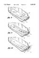
- FIG. 1is a front elevational view of an air bag cover constructed in accordance with the present invention
- FIG. 2is a rear elevational view of an air bag cover of the present invention
- FIG. 3is a cross sectional view of the air bag cover of the present invention taken along lines 3--3 of FIG. 2;
- FIG. 4is a perspective view illustrating a sheet of decorative applique material of the present invention being die cut into predetermined shapes
- FIG. 5is a perspective view illustrating the applique film and plastic liner of the present invention.
- FIG. 6is a perspective view of the applique film and plastic liner vacuum formed and bonded together
- FIG. 7is a perspective view of the applique assembly of the present invention illustrating connecting towers
- FIG. 8is a fragmentary, cross sectional view of an applique assembly attached to an air bag cover by a hot/cold upset method of the present invention
- FIG. 9is a fragmentary, cross sectional view of an applique assembly attached to an air bag cover by an thermal, pressurized method of the present invention.
- FIG. 10is a fragmentary, cross sectional view of an applique assembly attached to an air bag cover by an in-mold decorating method of the present invention
- FIG. 11is a cross section view of an alternative embodiment of the applique assembly attached to the air bag cover illustrating use of a washer plate.
- the cover 10includes a decorative applique assembly 12 affixed thereon.
- the applique assembly 12is shown in FIG. 1 affixed to a front cover 14.
- the front cover 14has an arcuate outer surface 16 and an inner surface 18.
- the side panels 20, 22, 24 and 26extend from the front cover 14, respectively.
- the air bag cover 10is manufactured from a flexible thermoplastic material such as commercially available "Santoprene" 201-87 provided by Advanced Elastomers Systems of Auburn Hills, Mich.
- a "U" shaped continuous seam 28is shown in FIG. 2 extending around the outer perimeter of the inner surface 18 of air bag cover 10.
- An uninflated air bag 30is shown directly adjacent inner surface 18 in FIG. 3.
- the air bag cover 10is designed to enclose uninflated air bag 30 and is usually positioned upon the steering wheel (not shown) of the automotive vehicle.
- FIG. 5there is shown a decorative applique membrane or film 32 and a plastic liner 34.
- the present inventioncontemplates use of most contemporary decorative appliques including wood grain simulations, chromed or silvered appliques and textured appliques.
- the decorative applique film 32is a thin membrane having a thickness of less than 0.5 millimeters.
- the plastic liner secured to the decorative appliqueis approximately 0.5 millimeters thick.
- the plastic liner 34is extruded onto the decorative applique film 32 in a conventional manner as shown in FIG. 4 to form a sheet of decorative material 35 having a top layer 31 of decorative material and bottom layer 33 of plastic liner.
- the plastic liner 34is die cut into predetermined shapes as shown in FIG. 4.
- the predetermined shapes or decorative applique members 41are vacuum formed into a shape corresponding to an arcuate portion of the air bag cover.
- the decorative applique member 41is insert molded with a plastic base 36 to form the decorative applique assembly 12.
- the plastic base 36is made of the same plastic material as air bag cover 10.
- Plastic liner 34is similarly made of the same material as the air bag cover or from an AVS plastic material.
- the plastic base 36includes a plurality of connecting towers 40 located on one side thereof. As shown in FIGS. 2 and 3, these connecting towers are positioned correspondingly to fastening apertures 42 which extend completely through the front cover of the air bag cover 10.
- Rear panel 44having an outer attachment seam 46.
- Rear panel 44in conjunction with outer seam 46 forms a hollow compartment 48.
- Rear panel 44may be hot plate welded, heat staked or otherwise attached to the inner surface 18 of front cover 14.
- Rear panel 44does not cover or overlap seam 28 since this may hinder or possibly prevent separation of the front cover at seam 28 upon inflation of the air bag.
- the hollow compartment 48houses a switch assembly 50 including electrical leads 52.
- Switch assembly 50includes a pair of spaced electrically conductive surfaces each connected to one electrical lead 52 and an insulating layer (not shown), therebetween as illustrated in co-pending application Ser. No. 7/984,326 filed Dec. 2, 1992.
- electrical leads 52are connected to the automobile electrical system for providing current to the switch assembly upon actuation of the switch assembly from the outer surface of the front cover system.
- the switch assembly 50operates in a conventional pressure sensitive manner by closing the circuit path formed by the electrical leads and the conductive surfaces by manual actuation of a corresponding portion of the front cover 14.
- the corresponding front cover portion or activation section 54is shown in phantom in FIG. 1.
- Switch assembly 50 in combination with air bag cover 10allows pressure sensitive operation of an automotive horn or other electrically controllable device.
- decorative applique assembly 12is shown affixed to air bag cover 10.
- the decorative applique assembly 12is disposed adjacent seam 28 in a non-overlapping fashion to prevent any interference of assembly 12 with inflation or exit of the air bag upon operation.
- the decorative applique assembly 12is therefore located, as illustrated in FIG. 2, sufficiently below seam 28 such that the attendant explosive effect that occurs upon inflation and exit of the air bag will move separable front cover section 56 away from decorative applique assembly 12.
- a flap segment 57acts as a live hinge when air bag inflation and exit occurs.
- FIG. 1illustrates air bag cover 10 including a simulated wood grain decorative applique 12. Simulated wood grain applique 12 is bonded to a decorative applique assembly as discussed in detail above.
- Air bag cover 10provides a decorative appearance by the addition of the decorative applique 12 without effecting the operable conditions of the air bag cover.
- the decorative applique assemblyincluding the decorative applique is affixed to the air bag cover with sufficient strength and at a location such that the assembly will not affect the inflation and subsequent exit of the inflating air bag from the cover.
- Applique film 32is bonded to plastic liner by the extrusion process such that the applique film will not separate from the plastic liner 34 during air bag inflation.
- insert molding the decorative applique member to the plastic basealso insures that no fragmentation of the decorative applique assembly will occur during air bag inflation.
- the methodincludes providing an air bag cover 10 having a seam 28, a decorative applique film segment 32, a plastic liner 34 having a first surface 38 and a second surface 39 and a plastic base 36.
- the preferred methodincludes providing a sheet of decorative applique film (not shown).
- a plastic liner liner 34is extruded directly onto the decorative applique film to form a sheet of decorative applique material 35.
- the sheet of decorative applique materialis extruded through a die having a thin slit (not shown) and then a heated plastic material is extruded directly onto the applique material, bonding the two surfaces together. This conventional extrusion process secures the first surface 38 of the plastic liner 34 to the decorative applique film.
- Decorative applique material 35is next die cut into a predetermined shape forming a decorative applique member 41.
- the decorative applique memberis then conventionally vacuum formed into a shape corresponding to an arcuate portion 16 of the air bag cover 10.
- the decorative applique memberis finally placed in an article defining cavity of a mold (not shown) shaped correspondingly to plastic base 36.
- Plasticis next injected into the mold cavity and decorative applique member is thereby insert molded with plastic base 36 to form decorative applique assembly 12.
- the decorative applique assembly 12is finally secured to the air bag cover 10 in a non-overlapping fashion with the seam 28 such that the plastic base 36 will not detach from the air bag cover when the uninflated air bag inflates and exits the air bag cover.
- an alternative methodincludes the steps of providing an air bag cover 10 having a seam 28 and at least one fastening aperture 42, a decorative applique film segment 32, a plastic liner 34 having a first surface 38 and a second surface 39 and a plastic base 36 having a connecting tower 40. As described above, the decorative applique film segment 32 is secured to the first surface 38 of the plastic liner 34 as described above.
- the plastic base 36is then secured to the second surface 39 of the plastic liner to form the decorative applique assembly 12.
- the decorative applique assembly 12is attached to the air bag cover 10 in a non-overlapping fashion with the seam 28 such that the plastic base 36 will not detach from the air bag cover when the uninflated air bag inflates and exits the air bag cover.
- the decorative applique assemblyis attached to the air bag cover 10 by inserting connecting tower 40 through fastening aperture 42 such that a portion 58 of the connecting tower extends out from the fastening aperture 42.
- the portion 58is then deformed to form a retaining member 60 larger in diameter than the fastening aperture 42, thereby affixing the applique to the air bag cover.
- the preferred method of deformingincludes the steps of applying a stream of heated air to portion 58 to melt the portion and applying a cold stake directly to melted portion 58 to form retaining member 60.
- the process of using hot air in conjunction with a relatively cool, fixed, die or stakeis known in the art as a "hot-cold upset" manufacturing method.
- yet another alternative methodincludes all the preceding steps and further includes providing a washer plate 62 having a central aperture 64 extending therethrough.
- the washer plateis then placed onto the connecting tower such that the a second portion 66 of the connecting tower extends through the central aperture 64 and the washer plate encircles the connecting tower.
- the second portion 66 of the connecting toweris then heated until portion 66 melts onto washer plate 62 to form a retaining button 68.
- a further method of applying the decorative appliquecomprises insert molding the decorative applique of the present invention onto the air bag cover.
- the decorative applique assembly 12is first made in accordance with the method described above.
- the decorative applique assembly 12is next placed in the article defining cavity 70 of a mold 71.
- the mold 71is shaped correspondingly to the shape of the air bag cover 10.
- a plastic materialis injected into cavity 70 around decorative applique assembly 12 thereby molding the decorative applique in place and fastening the applique to the now molded air bag cover 10.
- FIG. 9A still further method of fastening the decorative applique to the air bag cover is shown in FIG. 9.
- the methodcomprises the steps of providing the air bag cover 10 with at least one fastening aperture 42 extending therethrough, a plastic base 36 with at least one connecting tower 40 and an electrical conductor 72 disposed between the decorative applique assembly 12 and the air bag cover 10.
- the decorative applique assemblyis attached to the air bag cover by inserting the connecting tower 40 through the fastening aperture 42 such that a portion of said connecting tower 58 extends from the fastening aperture 42.
- a pressure of approximately 5 to 15 pounds per square inchis then applied to the decorative applique assembly 12 and the air bag cover 10.
- An electrical currentis applied to the electrical conductor thereby heating the conductor and bonding the decorative applique assembly 12 to the air bag cover 10.
- the conductoris heated to a temperature in a range from 300 to 500 degrees fahrenheit for approximately 2 to 5 seconds to adequately melt the abuttingly engaged portions of the decorative assembly 12 and air bag cover 10.
- the pressureis applied prior to heating the conductor, throughout the heating process, and for a short time after the electrical current is terminated. The pressure is applied for approximately a total of 8 seconds.
Landscapes
- Engineering & Computer Science (AREA)
- Mechanical Engineering (AREA)
- Air Bags (AREA)
Abstract
Description
Claims (17)
Priority Applications (2)
| Application Number | Priority Date | Filing Date | Title |
|---|---|---|---|
| US08/140,594US5487557A (en) | 1993-10-20 | 1993-10-20 | Air bag cover having an applique fastened thereto and method of manufacturing same |
| US08/532,508US5529336A (en) | 1993-10-20 | 1995-09-22 | Air bag cover having an applique fastened thereto |
Applications Claiming Priority (1)
| Application Number | Priority Date | Filing Date | Title |
|---|---|---|---|
| US08/140,594US5487557A (en) | 1993-10-20 | 1993-10-20 | Air bag cover having an applique fastened thereto and method of manufacturing same |
Related Child Applications (1)
| Application Number | Title | Priority Date | Filing Date |
|---|---|---|---|
| US08/532,508ContinuationUS5529336A (en) | 1993-10-20 | 1995-09-22 | Air bag cover having an applique fastened thereto |
Publications (1)
| Publication Number | Publication Date |
|---|---|
| US5487557Atrue US5487557A (en) | 1996-01-30 |
Family
ID=22491951
Family Applications (2)
| Application Number | Title | Priority Date | Filing Date |
|---|---|---|---|
| US08/140,594Expired - LifetimeUS5487557A (en) | 1993-10-20 | 1993-10-20 | Air bag cover having an applique fastened thereto and method of manufacturing same |
| US08/532,508Expired - LifetimeUS5529336A (en) | 1993-10-20 | 1995-09-22 | Air bag cover having an applique fastened thereto |
Family Applications After (1)
| Application Number | Title | Priority Date | Filing Date |
|---|---|---|---|
| US08/532,508Expired - LifetimeUS5529336A (en) | 1993-10-20 | 1995-09-22 | Air bag cover having an applique fastened thereto |
Country Status (1)
| Country | Link |
|---|---|
| US (2) | US5487557A (en) |
Cited By (24)
| Publication number | Priority date | Publication date | Assignee | Title |
|---|---|---|---|---|
| EP0835788A1 (en)* | 1996-10-11 | 1998-04-15 | TRW Occupant Restraint Systems GmbH | Airbag cover for a vehicle passenger restraint system |
| US5851022A (en)* | 1995-03-31 | 1998-12-22 | Toyoda Gosei Co., Ltd. | Air bag pad with decorative device |
| US5901977A (en)* | 1997-09-25 | 1999-05-11 | Textron Automotive Company, Inc. | Applique for concealing and retaining cover tear seam for air bag |
| US5922368A (en)* | 1997-04-24 | 1999-07-13 | Larry J. Winget | Injection molding apparatus for molding thermoplastic air bag covers |
| US6053526A (en)* | 1998-04-06 | 2000-04-25 | Larry J. Winget | Air bag cover assembly having a membrane switch and an ornamental pad permanently fastened thereto and method of making same |
| US6082762A (en)* | 1998-05-22 | 2000-07-04 | Larry J. Winget | Air bag cover having a decorative applique preform bonded thereto and method of making same |
| US6132662A (en)* | 1998-08-31 | 2000-10-17 | Patent Holding Company | Foil-covered plastic part and method of making same |
| US6180207B1 (en) | 1998-08-31 | 2001-01-30 | Patent Holding Company | Foil-covered automatic interior plastic part having a decorative preform and method of making same |
| US6209905B1 (en) | 1998-08-31 | 2001-04-03 | Patent Holding Company | Air bag cover having a flexible decorative badge |
| US6251202B1 (en) | 1999-05-05 | 2001-06-26 | Patent Holding Company | Method and system for bonding plastic parts together |
| US6322100B1 (en)* | 1998-10-26 | 2001-11-27 | Trw Inc. | Deployment structure for an inflatable vehicle occupant protection device |
| US6347806B1 (en) | 2000-01-21 | 2002-02-19 | Patent Holding Company | Snap-on thermoplastic air bag cover with enhanced moldability |
| US20020053396A1 (en)* | 1999-05-05 | 2002-05-09 | Larry J. Winget | Method and system for manufacturing an air bag cover assembly including a switch |
| US6563069B2 (en) | 2001-06-07 | 2003-05-13 | Delphi Technologies, Inc. | Horn switch |
| US6568707B2 (en) | 2001-02-23 | 2003-05-27 | Lear Corporation | Molded seamless vehicle interior panel for concealing an airbag |
| US6581311B1 (en) | 1999-08-05 | 2003-06-24 | Magna Interior Systems, Inc. | Clip assembly for an automotive vehicle |
| US20030165664A1 (en)* | 2002-03-01 | 2003-09-04 | Oakwood Custom Coating, Inc. | Method of making a composite panel and article made thereby |
| US20040131804A1 (en)* | 2002-10-31 | 2004-07-08 | Baker Jay J. | Multi-shelled applique, installation template, and method of trial positioning |
| US6760989B2 (en) | 2002-05-30 | 2004-07-13 | Delphi Technologies, Inc. | Decorative badge and method of making |
| US20050104338A1 (en)* | 2003-11-19 | 2005-05-19 | Quin Soderquist | Applique film airbag cover |
| US20060006588A1 (en)* | 1995-11-01 | 2006-01-12 | Patent Holding Company | Method of manufacturing an in-mold laminate composition |
| DE10316818B4 (en)* | 2003-04-11 | 2015-07-16 | Volkswagen Ag | Fastening arrangement for a decorative strip as an airbag cover on a vehicle |
| US20150232227A1 (en)* | 2006-07-03 | 2015-08-20 | Kautex Textron Gmbh & Co. Kg | Container of thermoplastic material |
| US20190248319A1 (en)* | 2016-09-27 | 2019-08-15 | Calsonic Kansei Corporation | Airbag lid and method of manufacturing the same |
Families Citing this family (11)
| Publication number | Priority date | Publication date | Assignee | Title |
|---|---|---|---|---|
| DE9402922U1 (en)* | 1994-02-22 | 1994-05-26 | Trw Repa Gmbh, 73553 Alfdorf | Cover for an airbag restraint system in vehicles |
| US20050225006A1 (en)* | 1995-11-01 | 2005-10-13 | Patent Holding Company | Method for molding metal-covered component |
| DE29706136U1 (en)* | 1997-03-24 | 1997-06-12 | Petri Ag, 63743 Aschaffenburg | Plaque attached to a base plate |
| US6818305B2 (en) | 1998-05-22 | 2004-11-16 | Patent Holding Company | Molding method and metal-covered component formed thereby |
| US6620371B1 (en) | 1998-05-22 | 2003-09-16 | Patent Holding Company | Method of manufacturing an in-mold laminate component |
| DE19829755B4 (en)* | 1998-07-03 | 2004-07-22 | Daimlerchrysler Ag | Airbag device for a motor vehicle |
| US6135489A (en)* | 1998-10-07 | 2000-10-24 | Trw Vehicle Safety Systems Inc. | Tear seam for air bag module cover |
| JP3833428B2 (en)* | 1999-12-14 | 2006-10-11 | 豊田合成株式会社 | Mounting structure for decorative products on molded products |
| US20040226400A1 (en)* | 2003-05-13 | 2004-11-18 | Eric Proudfit | Accessories for vehicles and method of manufacturing improved accessories for vehicles |
| JP2007503346A (en)* | 2003-08-21 | 2007-02-22 | コリンズ・アンド・アイクマン・プロダクツ・コーポレーション | Instrument panel covered with fabric |
| EP1706262A4 (en)* | 2003-12-31 | 2007-04-18 | Collins & Aikman Prod Co | In-mold lamination of a decorative product to a primary substrate |
Citations (23)
| Publication number | Priority date | Publication date | Assignee | Title |
|---|---|---|---|---|
| US3458386A (en)* | 1964-03-26 | 1969-07-29 | Glass Lab Co | Decorative trim strip and method of making same |
| US4139664A (en)* | 1977-03-21 | 1979-02-13 | Protective Treatments, Inc. | Mechanical securement of extrusions |
| US4325568A (en)* | 1980-07-28 | 1982-04-20 | General Motors Corporation | Modular occupant restraint system |
| US4515649A (en)* | 1980-07-17 | 1985-05-07 | The Standard Products Company | Thermoplastic elastomer molding |
| US4663210A (en)* | 1983-10-11 | 1987-05-05 | Dr. Ing. H.C.F. Porsche Aktiengesellschaft | Paneling member for the interior of automotive vehicles, especially a dashboard |
| US4934735A (en)* | 1988-12-12 | 1990-06-19 | General Motors Corporation | Switch assembly for modular occupant restraint system |
| JPH02171381A (en)* | 1988-12-23 | 1990-07-03 | Nissan Motor Co Ltd | steering wheel |
| JPH03143752A (en)* | 1989-10-30 | 1991-06-19 | Toyoda Gosei Co Ltd | Steering wheel provided with air bag device |
| DE4113591A1 (en)* | 1990-04-27 | 1991-11-07 | Toyoda Gosei Kk | STEERING WHEEL WITH AN AIR BAG SYSTEM |
| US5085462A (en)* | 1990-06-29 | 1992-02-04 | Gualtier Quentin E | Airbag and vehicle horn switch assembly |
| US5110647A (en)* | 1988-12-26 | 1992-05-05 | Takata Corporation | Cover for a vehicle air bag |
| DE4035975A1 (en)* | 1990-11-12 | 1992-05-14 | Erwin Schaefer | Leather cover for crash plates on steering wheel - incorporates fracture lines for emergence of air bag |
| JPH04151345A (en)* | 1990-09-18 | 1992-05-25 | Inoac Corp | Manufacturing method for automotive airbag door skin |
| GB2252274A (en)* | 1991-02-01 | 1992-08-05 | Jaguar Cars | A cover for an air bag module |
| US5180187A (en)* | 1989-02-18 | 1993-01-19 | Daimler-Benz Ag | Cover for an airbag unit and the process for producing it |
| JPH0524495A (en)* | 1991-07-20 | 1993-02-02 | Mazda Motor Corp | Lid structure for assistant driver's seat air bag device |
| US5186490A (en)* | 1991-09-23 | 1993-02-16 | Morton International, Inc. | Driver cover integral horn switch with solid reinforcement structure |
| JPH05139231A (en)* | 1991-11-19 | 1993-06-08 | Toyoda Gosei Co Ltd | Pad of airbag device |
| GB2262488A (en)* | 1991-12-17 | 1993-06-23 | Takata Corp | A cover for an air bag. |
| US5226998A (en)* | 1991-12-02 | 1993-07-13 | Plastic Trim, Inc. | Process for making a vehicle molding |
| US5294147A (en)* | 1991-07-13 | 1994-03-15 | Uta Clifford Limited | Crash protection device |
| US5369232A (en)* | 1993-07-23 | 1994-11-29 | Morton International, Inc. | Driver side airbag module cover and horn switch |
| US5395668A (en)* | 1990-08-29 | 1995-03-07 | Toyoda Gosei Co., Ltd. | Air bag apparatus |
Family Cites Families (8)
| Publication number | Priority date | Publication date | Assignee | Title |
|---|---|---|---|---|
| US5283404A (en)* | 1992-05-27 | 1994-02-01 | Morton International, Inc. | Minimum float, serviceable center blow horn switch in driver side air bag module |
| US5280946A (en)* | 1992-06-01 | 1994-01-25 | Morton International, Inc. | Cover for air bag installation |
| US5239147A (en)* | 1992-08-03 | 1993-08-24 | Morton International, Inc. | Floating, serviceable horn switch, air bag modules |
| FR2694530A1 (en)* | 1992-08-07 | 1994-02-11 | Morton Int Inc | Container for safety pad. |
| US5306040A (en)* | 1993-03-17 | 1994-04-26 | Morton International, Inc. | Cover for airbag |
| US5342086A (en)* | 1993-05-03 | 1994-08-30 | Morton International, Inc. | Closure for an inflatable restraint system |
| US5338060A (en)* | 1993-06-18 | 1994-08-16 | Morton International, Inc. | Energy dissipation features in air bag closures |
| US5322324A (en)* | 1993-08-03 | 1994-06-21 | Morton International, Inc. | Cover for an inflatable air bag housing |
- 1993
- 1993-10-20USUS08/140,594patent/US5487557A/ennot_activeExpired - Lifetime
- 1995
- 1995-09-22USUS08/532,508patent/US5529336A/ennot_activeExpired - Lifetime
Patent Citations (23)
| Publication number | Priority date | Publication date | Assignee | Title |
|---|---|---|---|---|
| US3458386A (en)* | 1964-03-26 | 1969-07-29 | Glass Lab Co | Decorative trim strip and method of making same |
| US4139664A (en)* | 1977-03-21 | 1979-02-13 | Protective Treatments, Inc. | Mechanical securement of extrusions |
| US4515649A (en)* | 1980-07-17 | 1985-05-07 | The Standard Products Company | Thermoplastic elastomer molding |
| US4325568A (en)* | 1980-07-28 | 1982-04-20 | General Motors Corporation | Modular occupant restraint system |
| US4663210A (en)* | 1983-10-11 | 1987-05-05 | Dr. Ing. H.C.F. Porsche Aktiengesellschaft | Paneling member for the interior of automotive vehicles, especially a dashboard |
| US4934735A (en)* | 1988-12-12 | 1990-06-19 | General Motors Corporation | Switch assembly for modular occupant restraint system |
| JPH02171381A (en)* | 1988-12-23 | 1990-07-03 | Nissan Motor Co Ltd | steering wheel |
| US5110647A (en)* | 1988-12-26 | 1992-05-05 | Takata Corporation | Cover for a vehicle air bag |
| US5180187A (en)* | 1989-02-18 | 1993-01-19 | Daimler-Benz Ag | Cover for an airbag unit and the process for producing it |
| JPH03143752A (en)* | 1989-10-30 | 1991-06-19 | Toyoda Gosei Co Ltd | Steering wheel provided with air bag device |
| DE4113591A1 (en)* | 1990-04-27 | 1991-11-07 | Toyoda Gosei Kk | STEERING WHEEL WITH AN AIR BAG SYSTEM |
| US5085462A (en)* | 1990-06-29 | 1992-02-04 | Gualtier Quentin E | Airbag and vehicle horn switch assembly |
| US5395668A (en)* | 1990-08-29 | 1995-03-07 | Toyoda Gosei Co., Ltd. | Air bag apparatus |
| JPH04151345A (en)* | 1990-09-18 | 1992-05-25 | Inoac Corp | Manufacturing method for automotive airbag door skin |
| DE4035975A1 (en)* | 1990-11-12 | 1992-05-14 | Erwin Schaefer | Leather cover for crash plates on steering wheel - incorporates fracture lines for emergence of air bag |
| GB2252274A (en)* | 1991-02-01 | 1992-08-05 | Jaguar Cars | A cover for an air bag module |
| US5294147A (en)* | 1991-07-13 | 1994-03-15 | Uta Clifford Limited | Crash protection device |
| JPH0524495A (en)* | 1991-07-20 | 1993-02-02 | Mazda Motor Corp | Lid structure for assistant driver's seat air bag device |
| US5186490A (en)* | 1991-09-23 | 1993-02-16 | Morton International, Inc. | Driver cover integral horn switch with solid reinforcement structure |
| JPH05139231A (en)* | 1991-11-19 | 1993-06-08 | Toyoda Gosei Co Ltd | Pad of airbag device |
| US5226998A (en)* | 1991-12-02 | 1993-07-13 | Plastic Trim, Inc. | Process for making a vehicle molding |
| GB2262488A (en)* | 1991-12-17 | 1993-06-23 | Takata Corp | A cover for an air bag. |
| US5369232A (en)* | 1993-07-23 | 1994-11-29 | Morton International, Inc. | Driver side airbag module cover and horn switch |
Cited By (38)
| Publication number | Priority date | Publication date | Assignee | Title |
|---|---|---|---|---|
| US5851022A (en)* | 1995-03-31 | 1998-12-22 | Toyoda Gosei Co., Ltd. | Air bag pad with decorative device |
| US7101505B2 (en) | 1995-11-01 | 2006-09-05 | Cadence Innovation Llc | Method of manufacturing an in-mold laminate composition |
| US20060006588A1 (en)* | 1995-11-01 | 2006-01-12 | Patent Holding Company | Method of manufacturing an in-mold laminate composition |
| US20060210662A1 (en)* | 1995-11-01 | 2006-09-21 | Cadence Innovation Llc | Mehtod of manufacturing an in-mold laminate component |
| US7425122B2 (en) | 1995-11-01 | 2008-09-16 | Cadence Innovation Llc. | Method of manufacturing an in-mold laminate component |
| EP0835788A1 (en)* | 1996-10-11 | 1998-04-15 | TRW Occupant Restraint Systems GmbH | Airbag cover for a vehicle passenger restraint system |
| US5922368A (en)* | 1997-04-24 | 1999-07-13 | Larry J. Winget | Injection molding apparatus for molding thermoplastic air bag covers |
| US5901977A (en)* | 1997-09-25 | 1999-05-11 | Textron Automotive Company, Inc. | Applique for concealing and retaining cover tear seam for air bag |
| US6053526A (en)* | 1998-04-06 | 2000-04-25 | Larry J. Winget | Air bag cover assembly having a membrane switch and an ornamental pad permanently fastened thereto and method of making same |
| US6158764A (en)* | 1998-04-06 | 2000-12-12 | Larry J. Winget | Air bag cover and method of making same |
| US6082762A (en)* | 1998-05-22 | 2000-07-04 | Larry J. Winget | Air bag cover having a decorative applique preform bonded thereto and method of making same |
| US6398897B1 (en) | 1998-05-22 | 2002-06-04 | Patent Holding Company | Foil-covered automotive interior plastic part having a decorative preform and method of making same |
| US6395219B1 (en) | 1998-05-22 | 2002-05-28 | Patent Holding Company | Method of making an air bag cover having a decorative applique preform bonded thereto |
| US6180207B1 (en) | 1998-08-31 | 2001-01-30 | Patent Holding Company | Foil-covered automatic interior plastic part having a decorative preform and method of making same |
| DE19941433B4 (en)* | 1998-08-31 | 2007-04-12 | Winget, Larry J., Fraser | An airbag cover with a preformed decorative applique and method of making the same |
| US6209905B1 (en) | 1998-08-31 | 2001-04-03 | Patent Holding Company | Air bag cover having a flexible decorative badge |
| US6132662A (en)* | 1998-08-31 | 2000-10-17 | Patent Holding Company | Foil-covered plastic part and method of making same |
| US6322100B1 (en)* | 1998-10-26 | 2001-11-27 | Trw Inc. | Deployment structure for an inflatable vehicle occupant protection device |
| US6579402B1 (en) | 1999-05-05 | 2003-06-17 | Patent Holding Company | Method and system for manufacturing an air bag cover assembly including a switch |
| US20020053396A1 (en)* | 1999-05-05 | 2002-05-09 | Larry J. Winget | Method and system for manufacturing an air bag cover assembly including a switch |
| US6251202B1 (en) | 1999-05-05 | 2001-06-26 | Patent Holding Company | Method and system for bonding plastic parts together |
| US6619358B2 (en) | 1999-05-05 | 2003-09-16 | Patent Holding Company | Method and system for bonding plastic parts together |
| US6881296B2 (en) | 1999-05-05 | 2005-04-19 | Patent Holding Company | Method and system for manufacturing an air bag cover assembly including a switch |
| US6581311B1 (en) | 1999-08-05 | 2003-06-24 | Magna Interior Systems, Inc. | Clip assembly for an automotive vehicle |
| US6347806B1 (en) | 2000-01-21 | 2002-02-19 | Patent Holding Company | Snap-on thermoplastic air bag cover with enhanced moldability |
| US6872349B2 (en) | 2001-02-23 | 2005-03-29 | Lear Corporation | Molded seamless vehicle interior panel for concealing an airbag |
| US20030184064A1 (en)* | 2001-02-23 | 2003-10-02 | Lear Corporation | Molded seamless vehicle interior panel for concealing an airbag |
| US6568707B2 (en) | 2001-02-23 | 2003-05-27 | Lear Corporation | Molded seamless vehicle interior panel for concealing an airbag |
| US6563069B2 (en) | 2001-06-07 | 2003-05-13 | Delphi Technologies, Inc. | Horn switch |
| US20030165664A1 (en)* | 2002-03-01 | 2003-09-04 | Oakwood Custom Coating, Inc. | Method of making a composite panel and article made thereby |
| US6760989B2 (en) | 2002-05-30 | 2004-07-13 | Delphi Technologies, Inc. | Decorative badge and method of making |
| US20040131804A1 (en)* | 2002-10-31 | 2004-07-08 | Baker Jay J. | Multi-shelled applique, installation template, and method of trial positioning |
| WO2004041498A3 (en)* | 2002-10-31 | 2004-12-09 | Jamestown Plastics Inc | Multi-shelled appliqué, installation template, and method of trial positioning |
| DE10316818B4 (en)* | 2003-04-11 | 2015-07-16 | Volkswagen Ag | Fastening arrangement for a decorative strip as an airbag cover on a vehicle |
| US20050104338A1 (en)* | 2003-11-19 | 2005-05-19 | Quin Soderquist | Applique film airbag cover |
| US20150232227A1 (en)* | 2006-07-03 | 2015-08-20 | Kautex Textron Gmbh & Co. Kg | Container of thermoplastic material |
| US10370143B2 (en)* | 2006-07-03 | 2019-08-06 | Kautex Textron Gmbh & Co. Kg | Container of thermoplastic material |
| US20190248319A1 (en)* | 2016-09-27 | 2019-08-15 | Calsonic Kansei Corporation | Airbag lid and method of manufacturing the same |
Also Published As
| Publication number | Publication date |
|---|---|
| US5529336A (en) | 1996-06-25 |
Similar Documents
| Publication | Publication Date | Title |
|---|---|---|
| US5487557A (en) | Air bag cover having an applique fastened thereto and method of manufacturing same | |
| US6053526A (en) | Air bag cover assembly having a membrane switch and an ornamental pad permanently fastened thereto and method of making same | |
| US5154444A (en) | Air bag retainer with cutting flaps | |
| US5429784A (en) | Method for making a reinforced air bag door cover | |
| JP3499265B2 (en) | Device for producing an airbag cover and an invisible tear seam in this cover | |
| EP0688701B1 (en) | Windowed airbag cover and method of manufacture thereof | |
| EP0764563B1 (en) | Air bag cover and manufacturing method thereof | |
| US6398897B1 (en) | Foil-covered automotive interior plastic part having a decorative preform and method of making same | |
| US5252164A (en) | Method for making a supplemental impact restraint door and instrument panel system from single, unitary cover | |
| US6003895A (en) | Airbag pad with insert molded ornament | |
| US6082762A (en) | Air bag cover having a decorative applique preform bonded thereto and method of making same | |
| US6209905B1 (en) | Air bag cover having a flexible decorative badge | |
| JP2002508270A (en) | Skin for automotive airbag cover panels formed by casting different plastic materials | |
| US6592173B2 (en) | Method of making fused film plastic parts and parts made by such methods | |
| EP0808750B1 (en) | Integral steering wheel and air bag assembly | |
| US6353415B1 (en) | Molded in place antenna assembly and method of making same | |
| US5783016A (en) | Instrument panel having integrated airbag deployment door | |
| EP2569188B1 (en) | Vehicle interior assembly | |
| US5945956A (en) | Vehicular exterior trim accessory having a built-in antenna | |
| EP0288130A2 (en) | Interior trim foam product and method of fabrication thereof | |
| MXPA96004067A (en) | Airbag cover with tear seam, interface without seam and method and apparatus thereof. | |
| US20060175855A1 (en) | Color matched automtive trim and body part | |
| US20070278770A1 (en) | Insert molded feature for airbag covers | |
| US6539612B2 (en) | Method of manufacturing an automotive airbag enclosure with an embedded heating element | |
| US20030020263A1 (en) | Unitary composite air bag cover and method of making same |
Legal Events
| Date | Code | Title | Description |
|---|---|---|---|
| AS | Assignment | Owner name:WINGET, LARRY J., MICHIGAN Free format text:ASSIGNMENT OF ASSIGNORS INTEREST;ASSIGNOR:ECKHOUT, THOMAS L.;REEL/FRAME:006751/0371 Effective date:19931020 | |
| STCF | Information on status: patent grant | Free format text:PATENTED CASE | |
| FEPP | Fee payment procedure | Free format text:PAT HLDR NO LONGER CLAIMS SMALL ENT STAT AS INDIV INVENTOR (ORIGINAL EVENT CODE: LSM1); ENTITY STATUS OF PATENT OWNER: LARGE ENTITY | |
| FPAY | Fee payment | Year of fee payment:4 | |
| AS | Assignment | Owner name:PATENT HOLDING COMPANY, MICHIGAN Free format text:ASSIGNMENT OF ASSIGNORS INTEREST;ASSIGNOR:WINGET, LARRY J.;REEL/FRAME:011007/0337 Effective date:20000718 | |
| AS | Assignment | Owner name:BANK ONE, NA, MICHIGAN Free format text:SECURITY INTEREST;ASSIGNOR:PATENT HOLDING COMPANY;REEL/FRAME:013089/0677 Effective date:20020702 | |
| FPAY | Fee payment | Year of fee payment:8 | |
| AS | Assignment | Owner name:BLACK DIAMOND COMMERICAL FINANCE, LLC, C/O BLACK D Free format text:SECURITY INTEREST;ASSIGNOR:PATENT HOLDING COMPANY;REEL/FRAME:014327/0001 Effective date:20040107 | |
| AS | Assignment | Owner name:NEW VENTURE HOLDINGS, LLC, MICHIGAN Free format text:ASSIGNMENT OF ASSIGNORS INTEREST;ASSIGNORS:DELUXE PATTERN CORPORATION;FARM & COUNTRY REAL ESTATE COMPANY;PATENT HOLDING COMPANY;AND OTHERS;REEL/FRAME:016610/0200 Effective date:20050502 | |
| AS | Assignment | Owner name:CADENCE INNOVATION LLC, MICHIGAN Free format text:CHANGE OF NAME;ASSIGNOR:NEW VENTURE HOLDINGS, LLC;REEL/FRAME:017575/0145 Effective date:20051014 | |
| AS | Assignment | Owner name:BANK OF AMERICA, N.A., CALIFORNIA Free format text:SECURITY AGREEMENT;ASSIGNOR:NEW VENTURE HOLDINGS, LLC;REEL/FRAME:017946/0365 Effective date:20050502 | |
| AS | Assignment | Owner name:BANK OF AMERICA, N.A., CALIFORNIA Free format text:SECURITY INTEREST;ASSIGNORS:CADENCE INNOVATION LLC F/K/A;NEW VENTURE HOLDINGS, LLC;REEL/FRAME:018109/0095 Effective date:20050502 | |
| AS | Assignment | Owner name:BROOKS KUSHMAN P.C., MICHIGAN Free format text:SECURITY AGREEMENT;ASSIGNOR:NEW VENTURE HOLDINGS LLC;REEL/FRAME:018433/0266 Effective date:20050803 | |
| FPAY | Fee payment | Year of fee payment:12 | |
| AS | Assignment | Owner name:GLOBAL IP HOLDINGS LLC, MICHIGAN Free format text:ASSIGNMENT OF ASSIGNORS INTEREST;ASSIGNOR:CADENCE INNOVATION LLC;REEL/FRAME:033294/0328 Effective date:20131206 |