US5486853A - Electrical cable interface for electronic camera - Google Patents
Electrical cable interface for electronic cameraDownload PDFInfo
- Publication number
- US5486853A US5486853AUS08/355,036US35503694AUS5486853AUS 5486853 AUS5486853 AUS 5486853AUS 35503694 AUS35503694 AUS 35503694AUS 5486853 AUS5486853 AUS 5486853A
- Authority
- US
- United States
- Prior art keywords
- video
- signals
- signal
- analog
- analog video
- Prior art date
- Legal status (The legal status is an assumption and is not a legal conclusion. Google has not performed a legal analysis and makes no representation as to the accuracy of the status listed.)
- Expired - Lifetime
Links
Images

Classifications
- H—ELECTRICITY
- H04—ELECTRIC COMMUNICATION TECHNIQUE
- H04N—PICTORIAL COMMUNICATION, e.g. TELEVISION
- H04N23/00—Cameras or camera modules comprising electronic image sensors; Control thereof
- H04N23/60—Control of cameras or camera modules
- H04N23/66—Remote control of cameras or camera parts, e.g. by remote control devices
Definitions
- the inventionrelates to video imaging camera systems.
- NTSCNational Television Standards Committee
- PALPhase Alternate by Line
- SECAMSequential Color with Memory
- Each standardhas its own set of specifications, each defining, for example, its own horizontal line frequency, color burst frequency, and number of lines per frame.
- Video cameraswhether a professional television camera or a consumer-grade camcorder, process their video signals so that their images can be viewed on a display monitor conforming to one of the above described standards. More recently, video cameras are being used as inputs for computers, where the output is a computer monitor. No interface standard has been adopted for this use.
- Digital signal processinggenerally offers higher quality video through digital storage and transmission of signals thereby preserving the integrity of the signal. Digital processing also provides more accurate control and elimination of coupling components between circuits which can break down or distort the video signals.
- processing the "raw" analog signals from the video imaging pickup device of the camerais performed, either digitally or in the analog format, at the camera itself so that the output signal from the camera can be provided directly to a display monitor.
- the analog video signals from the video pickup deviceare first converted to digital signals using an A/D converter.
- Luminance and chroma signal processingis then performed on the digital signals, which are then encoded.
- the digitally encoded video signalsare then reconverted back, using a D/A converter, into one of the standard analog television formats (e.g., NTSC) for transmission or display on a monitor.
- standard analog television formatse.g., NTSC
- further digital signal processingunrelated to the digital camera processing performed within the camera, is desired, for example, to compress, decompress, or provide other functions.
- the NTSC analog video signalis transmitted from the camera to the host for further processing, converted once again to digital data, processed, and then reconverted once again to NTSC analog video for display on a monitor. With each conversion and reconversion of the video signal comes a degradation in the quality of the signal.
- certain information in the raw analog video signal, not needed by the NTSC receiveris forever lost and unrecoverable. This lost information may be useful to the subsequent digital processor.
- the digital video signalscan be transmitted either in serial or parallel format. Transmitting the digital video signals in parallel requires a larger electrical cable with many more wires and larger connectors to interface the cable to the external processor. For example, one parallel digital bus known as SMPTE RP-125 uses a 25 pin D-type subminiature connector. Another problem with transmitting digital signals is that electrical cables longer than 20 meters generally require equalization.
- the digital video datacan be transmitted over high speed serial interfaces.
- serial interfacesFor example, 8 bit (240 Mbit/sec) and 10 bit (270 Mbit/sec) serial transmission interfaces have been used.
- 8 bit and 10 bit data wordsare serialized and transmitted down a standard 75 ⁇ video coaxial cable or an optical fiber.
- serial interfacesgenerally require a much larger bandwidth for transmitting the video data: whereas analog NTSC requires 6 MHz, digital serial transmission of the NTSC signal requires over 100 Mbps.
- the inventionfeatures a video camera system including an electronic camera head where horizontal and vertical synchronizing signals and pixel clock signals are generated and transmitted along with analog video signals generated by a solid-state video imager to a remote host processor.
- the electronic camera headis connected, via an electrical cable, to the remote host processor having digital signal processing circuitry for processing the analog video signals.
- the analog signalsare converted to digital video signals and then processed by the digital signal processing circuitry.
- the horizontal and vertical synchronizing signals and pixel clock signalare added to the analog video signals generated by the solid-state video imager before being transmitted to the remote host processor.
- the analog video signalsare separated from the added horizontal and vertical synchronizing signals and pixel clock signal.
- the advantages of the inventionare numerous.
- all of the digitally performed "intelligence" processingis located within a remote host processor, such as a video processing card of a personal computer, with only the analog processing, needed to prepare the raw analog signals for noise-free transmission, remaining in the camera head.
- a remote host processorsuch as a video processing card of a personal computer
- the digitally processed signals at the host processormay be processed further for reasons not directly related to the digital camera processing. For example, in a video teleconferencing system, compression, decompression, or improved AGC and white balancing functions may be used to process the video images before being transmitted over a communications channel.
- the digital processing related to the camera processing functionsmay be ultimately merged with the video compression processing into a single processor. Tightly integrating the different processing functions provides an optimized system at a reduced cost and provides enhanced performance. The advantages of integrating different and more sophisticated processing functions will become more apparent with the continued increase in the power of digital signal processing integrated circuits.
- Moving the digital portion of the signal processing to the external host processorallows the electronic camera head to be smaller, thereby reducing its cost and increasing its reliability. Because the electronic camera head is only required to provide a minimally processed video analog signal, independent of any accepted television broadcasting standard, such as NTSC, simple camera circuits can be used. An NTSC, YUV, or Y/C modulator is not required to be included within the electronic camera head to condition the analog video signals into one of the adopted standards. Further, the camera may be format-independent, with one camera serving both PAL and NTSC markets.
- the electrical cablecan be made smaller and at a reduced cost since only a single pair of wires is needed for conveying the raw analog video signals between the camera head and external processor.
- An additional pair of wires for providing electrical power to the CCDmay also be used, unless the electronic camera head is battery operated, or if an external power supply is used.
- transmitting digital signals in parallel formatrequires a cable with many more wires and if the signals are transmitted serially, the bandwidth of the channel must be increased.
- the interfaceallows the use of widely different camera formats.
- the interfacemay be used with both interlaced and non-interlaced systems, as well as different resolution and scan rates.
- the remote host processorreceives data information including its resolution, scan rate and whether it is color or monochrome, from the solid-state imager so as to determine the appropriate digital processing.
- this approachfacilitates daisy-chaining multiple electronic cameras along the electrical cable which serves as a video bus.
- the camerasmay also be genlocked, with the cameras switched during transmission of active video.
- genlockingis the process of locking both sync and burst of one camera's output signal to sync and burst of another, so that the two signals are completely synchronous.
- Embodiments of the inventioninclude one or more of the following features.
- the video pickup device of the electronic camera headis preferably a charge coupled device (CCD).
- the electronic camera headincludes a sampling circuit for extracting the reset pulse carrier signal from the raw analog video signals generated by the CCD.
- the timing generating circuitryincludes an adder circuit for adding the horizontal and vertical synchronizing signals and the pixel clock signal to the demodulated analog video signals. In other embodiments, these three signals may be transmitted over separate wires of the cable or multiplexed together and transmitted over a single wire.
- a blanking circuitmay be used to blank a portion of the video signal waveform for each horizontally scanned line of a frame and at the beginning of each one of the two interlaced vertical fields of a frame.
- the adder circuitthen adds the horizontal and vertical synchronizing signals and pixel clock signal to the blanked portion.
- a circuitmay be added for providing gamma correction to the analog video signals before conveying the signals to the adder circuit.
- the host processorincludes a filtering circuit for receiving the analog signals from the camera head and for extracting the horizontal and vertical synchronizing signals and pixel clock signal from the analog video signals.
- a synchronizing circuit within the host processorreceives the pixel clock signal from the filtering circuit and synchronizes the digital video signal with a local clock of the host processor.
- the synchronized digital video signalsare then digitally processed by the digital signal processing circuitry of the host processor.
- the host processormay also include a D/A converter for converting the digital video signals, processed by the digital signal processing circuit, to analog video signals for transmission to a display monitor.
- the host processormay include additional digital signal processing, such as video compression or decompression circuitry for compressing or decompressing the digital video signals processed by the digital signal processing circuit.
- the digital signal processing circuitis merged with the video compression or decompression circuitry.
- the electronic camera headmay include a processor for receiving information from the video imaging pickup device and for providing the information to the adder circuit for adding to the analog video signal.
- This informationmay include camera identification, CCD type, serial number, self-test status, and lens status information.
- a method of providing an interface within an electronic camera having a solid-state video imagerincludes the following steps:
- one or more of the following stepsmay be included.
- a portion of the video signal waveform comprising the analog video signalsis blanked with the horizontal and vertical synchronizing signals and pixel clock signal added to the blanked portion.
- the demodulated video signalis gamma corrected.
- Data informatione.g., camera identification, CCD serial number
- a lens systemis positioned at a location distal to a front face of the solid-state video imager for focusing optical images on the front face of the CCD. The distance between the lens system and CCD is variably controlled to provide a focusing effect.
- Information control signalsfor example, camera control signals may be added by the external processor to the blanked portion for transmission to the electronic camera.
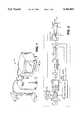
- FIG. 1is a perspective view of an electronic video camera system in accordance with the invention.
- FIG. 2is a block diagram of an electronic camera head of FIG. 1.
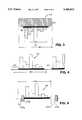
- FIG. 3represents the analog waveform of the video signal at letter a of FIG. 2.
- FIG. 4represents the analog waveform of the video signal at letter b of FIG. 2.
- FIG. 5represents the analog waveform of the video signal at letter c of FIG. 2.
- FIG. 6represents the analog waveform of the video signal between successive vertical synchronizing pulses.
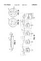
- FIG. 7Ais a cross-sectional view of the coaxial cable of FIG. 1.
- FIG. 7Bis a cross-sectional view of an alternate embodiment of the coaxial cable of FIG. 1.
- FIG. 8is a block diagram of the external video processing system of FIG. 1.
- FIG. 9is an alternate embodiment of an electronic camera head.
- FIG. 10is a schematic representation of a plurality of camera heads connected to a cable.
- a video camera system 10includes a video electronic camera head 12 mounted on a camera stand 11.
- Camera head 12provides analog video signals over an electrical cable 13 to a host processor, here a video processor card 14, inserted within personal computer 16, where the signals are digitally processed before being displayed on a monitor 17.
- a host processorhere a video processor card 14 inserted within personal computer 16, where the signals are digitally processed before being displayed on a monitor 17.
- camera head 12includes a lens 20 for focusing the image being viewed on the front face of an electro-optical sensor, here a charge-coupled device (CCD) 22 which converts optical images of received light into raw analog video signals.
- CCDcharge-coupled device
- OLPFoptical low pass filter
- OLPF 23a fluoride crystal which defocuses the image slightly, thereby improving the chroma response in the presence of high-spatial-frequency input images.
- OLPF 23also includes a filter for reducing the amount of infrared passing to CCD 22.
- CCD 22is an NTSC (National Television Standards Committee) format color stripe CCD, such as Product No. ICX058, manufactured by Sony Electronics, Inc., Component Products Division, San Jose, Calif.
- Timing signals provided by a timing generator 24shift the electrical charge packets within the CCD appropriately and also determine the sampling and frame rate at which each horizontally scanned line of pixels is read out from CCD 22.
- Timing generator 24, Product No. CXD 1265, manufactured by Sony Electronics, Inc., Component Products Division, San Jose, Calif.,is described in further detail below.
- a power supply 26, located within camera head 12,receives +12 volts from an external supply and generates output voltages of +20, +15, +5, and -9 volts for driving CCD 22.
- a representation of the analog video waveform output 28 from CCD 22 for one horizontally scanned lineshows that the raw analog video output includes a reset pulse carrier 30.
- Reset pulse carrier 30is an undesired and intrinsic artifact generated by CCD 22 and is generally removed to improve the transmission characteristics of the analog signal. Leaving the reset pulse carrier makes processing of the transmitted video signal more difficult, particularly if the length of electrical cable 13 is long since the bandwidth needed to transmit the signal without distortion is greater.
- the analog video outputis provided to a correlated double sampling circuit (CDS) 34 (FIG. 2), a demodulating circuit, which "strips off" the reset pulse carrier leaving a sampled analog waveform 36 as shown in FIG. 4.
- CDScorrelated double sampling circuit
- the sampled analog waveform 36is received by an automatic gain control (AGC) amplifier 38 which provides up to 25 dB of gain.
- AGCautomatic gain control
- the analog waveform input to the AGCis linear, with voltage directly proportional to incident light level.
- AGC amplifier 38is generally responsive to a peak signal level or may be adjusted by external command.
- the amplified waveformis then received by a gamma-correction circuit 40 which extends black levels and compresses white levels, in order to approximate the logarithmic sensitivity of the human eye.
- a timing pulse from timing generator 24indicates to gamma-correction circuit 40 that a portion of the waveform is a reference black shade 41 and is available to be used as a reference for DC level.
- the sampled analog waveformpasses to an adder circuit 46 which applies, for every horizontally scanned line, a horizontal sync pulse 45a from timing generator 24 as well as a subcarrier pixel clock pulse 45b (7.16 MHz for 410K imagers), within a horizontal blanking interval (HBI) 43, blanked by blanking circuit 42, of the analog waveform.
- HBIhorizontal blanking interval
- FIG. 5the resultant waveform present at the output of adder circuit 46 is designated by letter c of FIG. 2.
- the pixel clockgenerated by timing generator 24, serves as a reference indicating where the pixel information is located along the analog waveform and is used to synchronize the clock of the host video processor (described below).
- blanking circuit 42similarly provides blanking within vertical blanking intervals (VBI) 47.
- adder 46provides a vertical sync pulse 48 generated by timing generator 24.
- the analog waveform signalis then conveyed using a video buffer 44 over a coaxial cable 13 to host video processor card 14 where the signal is processed for viewing on display monitor 17.
- the analog video waveform passing to video processing card 14is a "minimally" processed analog video signal waveform which does not conform to any presently adopted standard but provides all of the information needed for decoding and processing.
- cable 13includes a conductor 50 for conveying the video signals surrounded by a shield conductor 52.
- a second pair of conductors 54, 56provide +12 volts power and power return, respectively, for CCD 22.
- the horizontal and vertical synchronizing signal and the pixel clock signalmay alternatively be transmitted over separate wires, 50a, 50b, 50c, respectively, as shown in FIG. 7B.
- the analog video signal from camera head 12is passed over cable 13 to host video processor card 14 where all of the digital processing occurs.
- the analog video signalis received by a sync separation circuit, such as Product No. EL4583C (Elantec, Inc., Milpitas, Calif.) video sync separator, which detects the sync pulses within HBI and VBI portions of the analog waveform and reproduces the horizontal and vertical synchronizing signals which were added by timing generator 24 within camera head 12.
- the analog video signalis also received by an analog/digital converter (ADC) 62 having at least 8 bit resolution and a 10 MHz sample rate.
- ADCanalog/digital converter
- an ADC circuitProduct No. AD876, manufactured by Analog Devices, Norwood, Mass.
- VCOvoltage control oscillator
- PLLphase-locked loop
- the digitized video signal from ADC 62is received by a digital camera processor 66, such as, Product No. CXD2130R, Sony Electronics, Inc., San Jose, Calif., which provides color stripe demodulation (CCD stripes to YUV) and automatic light balancing.
- digital camera processor 66may provide a multitude of additional tasks including some or all of the following:
- the digital signals processed by digital camera processor 66can be reconverted into analog format using a digital to analog converter (DAC) 67 for display on monitor 17.
- DACdigital to analog converter
- further digital signal processingmay be desirable before the signals are converted into their analog form.
- a video compression engine 68is used to compress the video signals in order to optimize transmission of the video data over a communication channel having limited bandwidth.
- bi-directional data communications between camera head 12 and host processor 14 for providing additional control and data base management functionsuses a processor 70 positioned within camera head 12.
- Control signalsare sent by computer 16 through host processor 14 along conductor 50 of cable 13 to processor 70 over line 78 during VBI portions of the analog video signal.
- the control signals received by processor 70 on line 78may, for example, be used to vary the incident light exposure by controlling an iris in the lens system, or to control the position of the lens in relation to the CCD for focussing or zooming.
- Other control signals for panning or tilting camera head 12 or for controlling AGC 38 in response to light received by CCD 22may also be provided by processor 70 along lines 75, 77, respectively. These control signals may also be transmitted to the camera head using an additional wire or pair of wires in cable 13.
- Processor 70may also be used to transmit data information within VBI portions of the analog video signal over line 50 by sending data along line 72 in the other direction as well.
- processor 70provides information to computer 16 including, for example, camera identification, type of CCD, serial number, self-test status, and lens status.
- cable 13may be modified to accommodate a multitude of camera heads 12.
- cable 13is terminated at both ends with a characteristic impedance matching that of the cable (e.g., 75 ⁇ ).
- Cameras 12 as well as video processing card 14are connected, in parallel, along the length of cable in daisy-chained fashion.
- the camerasmay be genlocked by effectively interconnected timing generators 24, in response to signals along line 80 with the cameras switched during transmission of the active video signals to provide wipe effects.
- bi-directional data communication between video processor card 14 and electronic camera head 12makes use of the vertical blanking intervals in the following way.
- Each VBIconsists of twenty horizontal intervals.
- Processor 70uses odd numbered lines 7, 9, 11, 13, 15, 17, and 19 for receiving data from video processing card 14 to camera head 12 and even numbered lines 8, 10, . . . 18 for transmitting data in the other direction.
- CCD 22may be any of a variety of color stripe CCDs and may, depending on the application or geographical area of use, be in the NTSC, PAL, or SECAM (Sequential Color with Memory) format.
Landscapes
- Engineering & Computer Science (AREA)
- Multimedia (AREA)
- Signal Processing (AREA)
- Studio Devices (AREA)
- Processing Of Color Television Signals (AREA)
Abstract
Description
Claims (33)
Priority Applications (1)
| Application Number | Priority Date | Filing Date | Title |
|---|---|---|---|
| US08/355,036US5486853A (en) | 1994-12-13 | 1994-12-13 | Electrical cable interface for electronic camera |
Applications Claiming Priority (1)
| Application Number | Priority Date | Filing Date | Title |
|---|---|---|---|
| US08/355,036US5486853A (en) | 1994-12-13 | 1994-12-13 | Electrical cable interface for electronic camera |
Publications (1)
| Publication Number | Publication Date |
|---|---|
| US5486853Atrue US5486853A (en) | 1996-01-23 |
Family
ID=23395976
Family Applications (1)
| Application Number | Title | Priority Date | Filing Date |
|---|---|---|---|
| US08/355,036Expired - LifetimeUS5486853A (en) | 1994-12-13 | 1994-12-13 | Electrical cable interface for electronic camera |
Country Status (1)
| Country | Link |
|---|---|
| US (1) | US5486853A (en) |
Cited By (97)
| Publication number | Priority date | Publication date | Assignee | Title |
|---|---|---|---|---|
| US5568192A (en)* | 1995-08-30 | 1996-10-22 | Intel Corporation | Method and apparatus for processing digital video camera signals |
| US5631701A (en)* | 1995-02-14 | 1997-05-20 | Fuji Photo Film Co., Ltd. | Image data transfer system operable with an electronic still camera |
| US5712680A (en)* | 1993-12-24 | 1998-01-27 | Canon Kabushiki Kaisha | Image pickup device for obtaining both moving and still images |
| US5715475A (en)* | 1994-12-29 | 1998-02-03 | Intel Corporation | Topological identification and initialization of a system for processing video information |
| WO1999026410A3 (en)* | 1997-11-17 | 1999-08-12 | Sony Electronics Inc | Charge-coupled device video camera with raw data format output and software implemented camera signal processing |
| US6031964A (en)* | 1996-06-20 | 2000-02-29 | Apple Computer, Inc. | System and method for using a unified memory architecture to implement a digital camera device |
| US6046769A (en)* | 1994-02-28 | 2000-04-04 | Canon Kabushiki Kaisha | Sensing apparatus |
| US20010017655A1 (en)* | 2000-02-28 | 2001-08-30 | Asahi Kogaku Kogyo Kabushiki Kaisha | Internet camera |
| US20010017656A1 (en)* | 2000-02-25 | 2001-08-30 | Asahi Kogaku Kogyo Kabushiki Kaisha | Internet camera system |
| US6288742B1 (en)* | 1995-09-21 | 2001-09-11 | Lucent Technologies Inc. | Video camera including multiple image sensors |
| US6295084B1 (en)* | 1995-03-10 | 2001-09-25 | Hitachi, Ltd. | System with analog interface and signal processor therefor |
| US20010024232A1 (en)* | 2000-02-18 | 2001-09-27 | Asahi Kogaku Kogyo Kabushiki Kaisha | Internet camera |
| US20020018126A1 (en)* | 1996-04-26 | 2002-02-14 | Canon Kabushiki Kaisha | Image sensing apparatus, image processing apparatus and image sensing system |
| US20020025163A1 (en)* | 2000-08-30 | 2002-02-28 | Urato Aruga | Solid image capturing device, lens unit and image capturing apparatus |
| US20020039139A1 (en)* | 1999-06-30 | 2002-04-04 | Logitech Europe S.A. | Video camera with major functions implemented in host software |
| US20020053087A1 (en)* | 2000-10-27 | 2002-05-02 | Asahi Kogaku Kogyo Kabushiki Kaisha | Internet camera system |
| US6392698B1 (en)* | 1996-12-06 | 2002-05-21 | Canon Kabushiki Kaisha | Camera head-detachable image sensing apparatus, image processing apparatus, and image sensing system constituted therewith |
| US6407773B1 (en) | 1994-02-28 | 2002-06-18 | Canon Kabushiki Kaisha | Image sensing apparatus |
| US6563534B1 (en)* | 1997-03-27 | 2003-05-13 | Hitachi Denshi Kabushiki Kaisha | High definition television camera apparatus for correcting a characteristic value of a video signal |
| EP1324593A2 (en)* | 2001-12-28 | 2003-07-02 | Karl Storz Imaging Inc. | Intelligent camera head |
| US6591060B1 (en)* | 1998-12-23 | 2003-07-08 | Xerox Corporation | Methods and systems for encoding command signals in a video signal with a video recorder |
| US6707490B1 (en)* | 1998-07-29 | 2004-03-16 | Minolta Co., Ltd. | Digital camera, camera main body and method for processing signal |
| US20040174129A1 (en)* | 2003-03-06 | 2004-09-09 | Yulun Wang | Medical tele-robotic system with a head worn device |
| US20050055727A1 (en)* | 1997-12-04 | 2005-03-10 | Pentax U.S.A., Inc. | Integrated internet/intranet camera |
| US20050125098A1 (en)* | 2003-12-09 | 2005-06-09 | Yulun Wang | Protocol for a remotely controlled videoconferencing robot |
| US20050204438A1 (en)* | 2004-02-26 | 2005-09-15 | Yulun Wang | Graphical interface for a remote presence system |
| US6965400B1 (en)* | 1997-02-07 | 2005-11-15 | Canon Kabushiki Kaisha | Video input apparatus and image pickup system including the apparatus |
| US7009644B1 (en) | 1999-12-15 | 2006-03-07 | Logitech Europe S.A. | Dynamic anomalous pixel detection and correction |
| US20060052676A1 (en)* | 2004-09-07 | 2006-03-09 | Yulun Wang | Tele-presence system that allows for remote monitoring/observation and review of a patient and their medical records |
| US20060082655A1 (en)* | 2004-10-15 | 2006-04-20 | Vanderwilt Patrick D | High definition pan tilt zoom camera with embedded microphones and thin cable for data and power |
| US20060082642A1 (en)* | 2002-07-25 | 2006-04-20 | Yulun Wang | Tele-robotic videoconferencing in a corporate environment |
| US20060088308A1 (en)* | 2004-10-15 | 2006-04-27 | Kenoyer Michael L | Camera support mechanism |
| US20060104633A1 (en)* | 2004-10-15 | 2006-05-18 | Kenoyer Michael L | High definition camera pan tilt mechanism |
| US20060104458A1 (en)* | 2004-10-15 | 2006-05-18 | Kenoyer Michael L | Video and audio conferencing system with spatial audio |
| US20060259193A1 (en)* | 2005-05-12 | 2006-11-16 | Yulun Wang | Telerobotic system with a dual application screen presentation |
| US7142731B1 (en)* | 1999-02-17 | 2006-11-28 | Nec Corporation | Image processing system |
| US20060269278A1 (en)* | 2004-10-15 | 2006-11-30 | Kenoyer Michael L | Coordinated camera pan tilt mechanism |
| US7158861B2 (en) | 2002-07-25 | 2007-01-02 | Intouch Technologies, Inc. | Tele-robotic system used to provide remote consultation services |
| US20070198130A1 (en)* | 2006-02-22 | 2007-08-23 | Yulun Wang | Graphical interface for a remote presence system |
| US20070291109A1 (en)* | 2006-06-15 | 2007-12-20 | Yulun Wang | Remote controlled mobile robot with auxillary input ports |
| US20080002045A1 (en)* | 2005-12-07 | 2008-01-03 | Alon Wallach | Wireless and CCTV megapixel digital camera for surveillance and unmanned air vehicles |
| US20080030611A1 (en)* | 2006-08-01 | 2008-02-07 | Jenkins Michael V | Dual Sensor Video Camera |
| US20080052026A1 (en)* | 2006-08-23 | 2008-02-28 | Qurio Holdings, Inc. | Configuring a content capture device for one or more service providers |
| US20080082211A1 (en)* | 2006-10-03 | 2008-04-03 | Yulun Wang | Remote presence display through remotely controlled robot |
| US20080115066A1 (en)* | 1998-12-31 | 2008-05-15 | Pavley John F | Method and apparatus for editing heterogeneous media objects in a digital imaging device |
| US20080281467A1 (en)* | 2007-05-09 | 2008-11-13 | Marco Pinter | Robot system that operates through a network firewall |
| US20090055023A1 (en)* | 2007-08-23 | 2009-02-26 | Derek Walters | Telepresence robot with a printer |
| USD589996S1 (en) | 2008-02-07 | 2009-04-07 | Lifesize Communications, Inc. | Flat mounted camera |
| USD589995S1 (en) | 2008-02-07 | 2009-04-07 | Lifesize Communications, Inc. | Mountable camera |
| USD590000S1 (en) | 2008-02-07 | 2009-04-07 | Lifesize Communications, Inc. | Camera stand |
| US20090244295A1 (en)* | 2008-03-31 | 2009-10-01 | Kabushiki Kaisha Toshiba | Imaging apparatus having camera control unit and separate camera head |
| US20100010672A1 (en)* | 2008-07-10 | 2010-01-14 | Yulun Wang | Docking system for a tele-presence robot |
| US20100191375A1 (en)* | 2009-01-29 | 2010-07-29 | Wright Timothy C | Documentation through a remote presence robot |
| US20110181723A1 (en)* | 2010-01-25 | 2011-07-28 | Denso Corporation | Vehicle circumference monitor apparatus |
| US20110190930A1 (en)* | 2010-02-04 | 2011-08-04 | Intouch Technologies, Inc. | Robot user interface for telepresence robot system |
| US20110187875A1 (en)* | 2010-02-04 | 2011-08-04 | Intouch Technologies, Inc. | Robot face used in a sterile environment |
| US20110213210A1 (en)* | 2009-08-26 | 2011-09-01 | Intouch Technologies, Inc. | Portable telepresence apparatus |
| US8102457B1 (en) | 1997-07-09 | 2012-01-24 | Flashpoint Technology, Inc. | Method and apparatus for correcting aspect ratio in a camera graphical user interface |
| US8350928B2 (en) | 1998-07-23 | 2013-01-08 | KDL Scan Deisgns LLC | Method and apparatus for automatically categorizing images in a digital camera |
| US8401275B2 (en) | 2004-07-13 | 2013-03-19 | Intouch Technologies, Inc. | Mobile robot with a head-based movement mapping scheme |
| US8515577B2 (en) | 2002-07-25 | 2013-08-20 | Yulun Wang | Medical tele-robotic system with a master remote station with an arbitrator |
| US20140055637A1 (en)* | 2011-04-04 | 2014-02-27 | Interlemo Holding S.A. | Installation for Conveying Signals Between a Video Camera Equipment and a Remote Equipment |
| US8836751B2 (en) | 2011-11-08 | 2014-09-16 | Intouch Technologies, Inc. | Tele-presence system with a user interface that displays different communication links |
| US8861750B2 (en) | 2008-04-17 | 2014-10-14 | Intouch Technologies, Inc. | Mobile tele-presence system with a microphone system |
| US8897920B2 (en) | 2009-04-17 | 2014-11-25 | Intouch Technologies, Inc. | Tele-presence robot system with software modularity, projector and laser pointer |
| US8902278B2 (en) | 2012-04-11 | 2014-12-02 | Intouch Technologies, Inc. | Systems and methods for visualizing and managing telepresence devices in healthcare networks |
| US8953034B1 (en)* | 2006-05-23 | 2015-02-10 | Milan Milosevic | Video imaging device with an integrated battery |
| US8965579B2 (en) | 2011-01-28 | 2015-02-24 | Intouch Technologies | Interfacing with a mobile telepresence robot |
| US8996165B2 (en) | 2008-10-21 | 2015-03-31 | Intouch Technologies, Inc. | Telepresence robot with a camera boom |
| US9089972B2 (en) | 2010-03-04 | 2015-07-28 | Intouch Technologies, Inc. | Remote presence system including a cart that supports a robot face and an overhead camera |
| US9098611B2 (en) | 2012-11-26 | 2015-08-04 | Intouch Technologies, Inc. | Enhanced video interaction for a user interface of a telepresence network |
| US9138891B2 (en) | 2008-11-25 | 2015-09-22 | Intouch Technologies, Inc. | Server connectivity control for tele-presence robot |
| US9174342B2 (en) | 2012-05-22 | 2015-11-03 | Intouch Technologies, Inc. | Social behavior rules for a medical telepresence robot |
| US9198728B2 (en) | 2005-09-30 | 2015-12-01 | Intouch Technologies, Inc. | Multi-camera mobile teleconferencing platform |
| US9224145B1 (en) | 2006-08-30 | 2015-12-29 | Qurio Holdings, Inc. | Venue based digital rights using capture device with digital watermarking capability |
| US9251313B2 (en) | 2012-04-11 | 2016-02-02 | Intouch Technologies, Inc. | Systems and methods for visualizing and managing telepresence devices in healthcare networks |
| US9264664B2 (en) | 2010-12-03 | 2016-02-16 | Intouch Technologies, Inc. | Systems and methods for dynamic bandwidth allocation |
| US9323250B2 (en) | 2011-01-28 | 2016-04-26 | Intouch Technologies, Inc. | Time-dependent navigation of telepresence robots |
| US9361021B2 (en) | 2012-05-22 | 2016-06-07 | Irobot Corporation | Graphical user interfaces including touchpad driving interfaces for telemedicine devices |
| US9381654B2 (en) | 2008-11-25 | 2016-07-05 | Intouch Technologies, Inc. | Server connectivity control for tele-presence robot |
| US20160198089A1 (en)* | 2014-03-03 | 2016-07-07 | Smk Corporation | Image processing system |
| US9429934B2 (en) | 2008-09-18 | 2016-08-30 | Intouch Technologies, Inc. | Mobile videoconferencing robot system with network adaptive driving |
| US9602765B2 (en) | 2009-08-26 | 2017-03-21 | Intouch Technologies, Inc. | Portable remote presence robot |
| US9842192B2 (en) | 2008-07-11 | 2017-12-12 | Intouch Technologies, Inc. | Tele-presence robot system with multi-cast features |
| US9974612B2 (en) | 2011-05-19 | 2018-05-22 | Intouch Technologies, Inc. | Enhanced diagnostics for a telepresence robot |
| US10343283B2 (en) | 2010-05-24 | 2019-07-09 | Intouch Technologies, Inc. | Telepresence robot system that can be accessed by a cellular phone |
| US10471588B2 (en) | 2008-04-14 | 2019-11-12 | Intouch Technologies, Inc. | Robotic based health care system |
| US10769739B2 (en) | 2011-04-25 | 2020-09-08 | Intouch Technologies, Inc. | Systems and methods for management of information among medical providers and facilities |
| US10808882B2 (en) | 2010-05-26 | 2020-10-20 | Intouch Technologies, Inc. | Tele-robotic system with a robot face placed on a chair |
| US10875182B2 (en) | 2008-03-20 | 2020-12-29 | Teladoc Health, Inc. | Remote presence system mounted to operating room hardware |
| US10956770B1 (en)* | 2017-11-14 | 2021-03-23 | Snap Inc. | Systems and methods for multi-device image processing |
| US11389064B2 (en) | 2018-04-27 | 2022-07-19 | Teladoc Health, Inc. | Telehealth cart that supports a removable tablet with seamless audio/video switching |
| US11636944B2 (en) | 2017-08-25 | 2023-04-25 | Teladoc Health, Inc. | Connectivity infrastructure for a telehealth platform |
| US11742094B2 (en) | 2017-07-25 | 2023-08-29 | Teladoc Health, Inc. | Modular telehealth cart with thermal imaging and touch screen user interface |
| US11862302B2 (en) | 2017-04-24 | 2024-01-02 | Teladoc Health, Inc. | Automated transcription and documentation of tele-health encounters |
| US12093036B2 (en) | 2011-01-21 | 2024-09-17 | Teladoc Health, Inc. | Telerobotic system with a dual application screen presentation |
| US12224059B2 (en) | 2011-02-16 | 2025-02-11 | Teladoc Health, Inc. | Systems and methods for network-based counseling |
Citations (2)
| Publication number | Priority date | Publication date | Assignee | Title |
|---|---|---|---|---|
| US4728804A (en)* | 1986-12-30 | 1988-03-01 | The Boeing Company | Scanning system with low sampling rate |
| US5389968A (en)* | 1991-04-11 | 1995-02-14 | Yugengaisha Wai-Kei Kikaku | CCD television camera with separated camera head |
- 1994
- 1994-12-13USUS08/355,036patent/US5486853A/ennot_activeExpired - Lifetime
Patent Citations (2)
| Publication number | Priority date | Publication date | Assignee | Title |
|---|---|---|---|---|
| US4728804A (en)* | 1986-12-30 | 1988-03-01 | The Boeing Company | Scanning system with low sampling rate |
| US5389968A (en)* | 1991-04-11 | 1995-02-14 | Yugengaisha Wai-Kei Kikaku | CCD television camera with separated camera head |
Cited By (218)
| Publication number | Priority date | Publication date | Assignee | Title |
|---|---|---|---|---|
| US5712680A (en)* | 1993-12-24 | 1998-01-27 | Canon Kabushiki Kaisha | Image pickup device for obtaining both moving and still images |
| US6498621B1 (en)* | 1994-02-28 | 2002-12-24 | Canon Kabushiki Kaisha | Image sensing apparatus |
| US6407773B1 (en) | 1994-02-28 | 2002-06-18 | Canon Kabushiki Kaisha | Image sensing apparatus |
| US6046769A (en)* | 1994-02-28 | 2000-04-04 | Canon Kabushiki Kaisha | Sensing apparatus |
| US5715475A (en)* | 1994-12-29 | 1998-02-03 | Intel Corporation | Topological identification and initialization of a system for processing video information |
| US5631701A (en)* | 1995-02-14 | 1997-05-20 | Fuji Photo Film Co., Ltd. | Image data transfer system operable with an electronic still camera |
| US6295084B1 (en)* | 1995-03-10 | 2001-09-25 | Hitachi, Ltd. | System with analog interface and signal processor therefor |
| US5568192A (en)* | 1995-08-30 | 1996-10-22 | Intel Corporation | Method and apparatus for processing digital video camera signals |
| US6288742B1 (en)* | 1995-09-21 | 2001-09-11 | Lucent Technologies Inc. | Video camera including multiple image sensors |
| US7804523B2 (en) | 1996-04-26 | 2010-09-28 | Canon Kabushiki Kaisha | Apparatus and system for camera head determination in an image sensing system |
| US20020018126A1 (en)* | 1996-04-26 | 2002-02-14 | Canon Kabushiki Kaisha | Image sensing apparatus, image processing apparatus and image sensing system |
| US6975351B2 (en)* | 1996-04-26 | 2005-12-13 | Canon Kabushiki Kaisha | Apparatus and system for camera head determination in an image sensing system |
| US20060007326A1 (en)* | 1996-04-26 | 2006-01-12 | Canon Kabushiki Kaisha | Apparatus and system for camera head determination in an image sensing system |
| US6031964A (en)* | 1996-06-20 | 2000-02-29 | Apple Computer, Inc. | System and method for using a unified memory architecture to implement a digital camera device |
| US6392698B1 (en)* | 1996-12-06 | 2002-05-21 | Canon Kabushiki Kaisha | Camera head-detachable image sensing apparatus, image processing apparatus, and image sensing system constituted therewith |
| US6965400B1 (en)* | 1997-02-07 | 2005-11-15 | Canon Kabushiki Kaisha | Video input apparatus and image pickup system including the apparatus |
| US6563534B1 (en)* | 1997-03-27 | 2003-05-13 | Hitachi Denshi Kabushiki Kaisha | High definition television camera apparatus for correcting a characteristic value of a video signal |
| US8102457B1 (en) | 1997-07-09 | 2012-01-24 | Flashpoint Technology, Inc. | Method and apparatus for correcting aspect ratio in a camera graphical user interface |
| US8970761B2 (en) | 1997-07-09 | 2015-03-03 | Flashpoint Technology, Inc. | Method and apparatus for correcting aspect ratio in a camera graphical user interface |
| US6285398B1 (en)* | 1997-11-17 | 2001-09-04 | Sony Corporation | Charge-coupled device video camera with raw data format output and software implemented camera signal processing |
| WO1999026410A3 (en)* | 1997-11-17 | 1999-08-12 | Sony Electronics Inc | Charge-coupled device video camera with raw data format output and software implemented camera signal processing |
| US20050146609A1 (en)* | 1997-12-04 | 2005-07-07 | Pentax U.S.A., Inc. | Method for sending image data from camera to CCTV network |
| US20100023982A1 (en)* | 1997-12-04 | 2010-01-28 | Pentax Of America, Inc. | Camera connectible to cctv network |
| US20070288974A1 (en)* | 1997-12-04 | 2007-12-13 | Pentax Of America, Inc. | Integrated internet camera |
| US20100023981A1 (en)* | 1997-12-04 | 2010-01-28 | Pentax Of America, Inc. | Method for sending image data from camera to cctv network |
| US20050055727A1 (en)* | 1997-12-04 | 2005-03-10 | Pentax U.S.A., Inc. | Integrated internet/intranet camera |
| US20050099519A1 (en)* | 1997-12-04 | 2005-05-12 | Pentax U.S.A., Inc. | Integrated internet camera |
| US7523481B2 (en) | 1997-12-04 | 2009-04-21 | Pentax Of America, Inc. | Integrated internet camera |
| US20050144653A1 (en)* | 1997-12-04 | 2005-06-30 | Pentax U.S.A., Inc. | Method of transmitting image data from standalone device |
| US20050149979A1 (en)* | 1997-12-04 | 2005-07-07 | Pentax U.S.A., Inc. | Standalone device connectible to CCTV network |
| US8381255B2 (en) | 1997-12-04 | 2013-02-19 | Axis Ab | Device for sending image data from camera to CCTV network |
| US20050146610A1 (en)* | 1997-12-04 | 2005-07-07 | Pentax U.S.A., Inc. | Camera connectible to CCTV network |
| US20070268373A1 (en)* | 1997-12-04 | 2007-11-22 | Pentax Of America, Inc. | Integrated internet camera |
| US7523480B2 (en) | 1997-12-04 | 2009-04-21 | Pentax Of America, Inc. | Integrated Internet camera |
| US7272845B2 (en) | 1997-12-04 | 2007-09-18 | Pentax Of America, Inc. | Integrated internet/intranet camera |
| US7962945B2 (en) | 1997-12-04 | 2011-06-14 | Axis Ab | Method for sending image data from camera to cctv network |
| US7425987B2 (en) | 1997-12-04 | 2008-09-16 | Pentax Of America, Inc. | Method of transmitting image data from standalone device |
| US7962946B2 (en) | 1997-12-04 | 2011-06-14 | Axis Ab | Camera connectible to CCTV network |
| US20110197241A1 (en)* | 1997-12-04 | 2011-08-11 | Axis Ab | Device for sending image data from camera to cctv network |
| US7644431B2 (en) | 1997-12-04 | 2010-01-05 | Pentax Of America, Inc. | Method for sending image data from camera to CCTV network |
| US7350224B2 (en) | 1997-12-04 | 2008-03-25 | Pentax Of America, Inc. | Integrated internet/intranet camera |
| US20060031902A1 (en)* | 1997-12-04 | 2006-02-09 | Pentax Of America, Inc. | Integrated internet camera |
| US20060031901A1 (en)* | 1997-12-04 | 2006-02-09 | Pentax Of America, Inc. | Integrated internet camera |
| US7640567B2 (en) | 1997-12-04 | 2009-12-29 | Pentax Of America, Inc. | Camera connectible to CCTV network |
| US7631335B2 (en) | 1997-12-04 | 2009-12-08 | Pentax Of America, Inc. | Integrated internet camera |
| US9621778B2 (en) | 1997-12-04 | 2017-04-11 | Axis Ab | Device for sending image data from camera to CCTV network |
| US7428004B2 (en) | 1997-12-04 | 2008-09-23 | Pentax Of America, Inc. | Standalone device connectible to CCTV network |
| US7428005B2 (en) | 1997-12-04 | 2008-09-23 | Pentax Of America, Inc. | Integrated Internet/intranet camera |
| US9143672B2 (en) | 1997-12-04 | 2015-09-22 | Axis Ab | Device for sending image data from camera to CCTV network |
| US7640568B2 (en) | 1997-12-04 | 2009-12-29 | Pentax Of America, Inc. | Integrated internet camera |
| US8836819B2 (en) | 1998-07-23 | 2014-09-16 | Kdl Scan Designs Llc | Method and apparatus for automatically categorizing images in a digital camera |
| US8531555B2 (en) | 1998-07-23 | 2013-09-10 | Kdl Scan Designs Llc | Method and apparatus for automatically categorizing images in a digital camera |
| US8350928B2 (en) | 1998-07-23 | 2013-01-08 | KDL Scan Deisgns LLC | Method and apparatus for automatically categorizing images in a digital camera |
| US6707490B1 (en)* | 1998-07-29 | 2004-03-16 | Minolta Co., Ltd. | Digital camera, camera main body and method for processing signal |
| US6591060B1 (en)* | 1998-12-23 | 2003-07-08 | Xerox Corporation | Methods and systems for encoding command signals in a video signal with a video recorder |
| US8972867B1 (en) | 1998-12-31 | 2015-03-03 | Flashpoint Technology, Inc. | Method and apparatus for editing heterogeneous media objects in a digital imaging device |
| US20080115066A1 (en)* | 1998-12-31 | 2008-05-15 | Pavley John F | Method and apparatus for editing heterogeneous media objects in a digital imaging device |
| US8127232B2 (en) | 1998-12-31 | 2012-02-28 | Flashpoint Technology, Inc. | Method and apparatus for editing heterogeneous media objects in a digital imaging device |
| US7142731B1 (en)* | 1999-02-17 | 2006-11-28 | Nec Corporation | Image processing system |
| US6995794B2 (en) | 1999-06-30 | 2006-02-07 | Logitech Europe S.A. | Video camera with major functions implemented in host software |
| US20020039139A1 (en)* | 1999-06-30 | 2002-04-04 | Logitech Europe S.A. | Video camera with major functions implemented in host software |
| US20050162531A1 (en)* | 1999-06-30 | 2005-07-28 | Logitech Europe S.A. | Video camera with major functions implemented in host software |
| US7009644B1 (en) | 1999-12-15 | 2006-03-07 | Logitech Europe S.A. | Dynamic anomalous pixel detection and correction |
| US6980232B2 (en) | 2000-02-18 | 2005-12-27 | Pentax Corporation | Image transmitting Internet camera |
| US20010024232A1 (en)* | 2000-02-18 | 2001-09-27 | Asahi Kogaku Kogyo Kabushiki Kaisha | Internet camera |
| US20010017656A1 (en)* | 2000-02-25 | 2001-08-30 | Asahi Kogaku Kogyo Kabushiki Kaisha | Internet camera system |
| US20010017655A1 (en)* | 2000-02-28 | 2001-08-30 | Asahi Kogaku Kogyo Kabushiki Kaisha | Internet camera |
| US6965398B2 (en) | 2000-02-28 | 2005-11-15 | Pentax Corporation | Internet camera |
| US20020025163A1 (en)* | 2000-08-30 | 2002-02-28 | Urato Aruga | Solid image capturing device, lens unit and image capturing apparatus |
| US6980241B2 (en)* | 2000-08-30 | 2005-12-27 | Chinon Kabushiki Kaisha | Solid image capturing device, lens unit and image capturing apparatus including an optical mask for storing characteristic data |
| US20020053087A1 (en)* | 2000-10-27 | 2002-05-02 | Asahi Kogaku Kogyo Kabushiki Kaisha | Internet camera system |
| US7562380B2 (en) | 2000-10-27 | 2009-07-14 | Hoya Corporation | Internet camera system |
| EP1324593A2 (en)* | 2001-12-28 | 2003-07-02 | Karl Storz Imaging Inc. | Intelligent camera head |
| US7158861B2 (en) | 2002-07-25 | 2007-01-02 | Intouch Technologies, Inc. | Tele-robotic system used to provide remote consultation services |
| US20080255703A1 (en)* | 2002-07-25 | 2008-10-16 | Yulun Wang | Medical tele-robotic system |
| USRE45870E1 (en) | 2002-07-25 | 2016-01-26 | Intouch Technologies, Inc. | Apparatus and method for patient rounding with a remote controlled robot |
| US20070021871A1 (en)* | 2002-07-25 | 2007-01-25 | Yulun Wang | Medical tele-robotic system |
| US20070112464A1 (en)* | 2002-07-25 | 2007-05-17 | Yulun Wang | Apparatus and method for patient rounding with a remote controlled robot |
| US10315312B2 (en) | 2002-07-25 | 2019-06-11 | Intouch Technologies, Inc. | Medical tele-robotic system with a master remote station with an arbitrator |
| US7289883B2 (en) | 2002-07-25 | 2007-10-30 | Intouch Technologies, Inc. | Apparatus and method for patient rounding with a remote controlled robot |
| US9849593B2 (en) | 2002-07-25 | 2017-12-26 | Intouch Technologies, Inc. | Medical tele-robotic system with a master remote station with an arbitrator |
| US8515577B2 (en) | 2002-07-25 | 2013-08-20 | Yulun Wang | Medical tele-robotic system with a master remote station with an arbitrator |
| US20090105882A1 (en)* | 2002-07-25 | 2009-04-23 | Intouch Technologies, Inc. | Medical Tele-Robotic System |
| US20060082642A1 (en)* | 2002-07-25 | 2006-04-20 | Yulun Wang | Tele-robotic videoconferencing in a corporate environment |
| US20080029536A1 (en)* | 2002-07-25 | 2008-02-07 | Intouch Technologies, Inc. | Medical tele-robotic system |
| US7593030B2 (en) | 2002-07-25 | 2009-09-22 | Intouch Technologies, Inc. | Tele-robotic videoconferencing in a corporate environment |
| US8209051B2 (en) | 2002-07-25 | 2012-06-26 | Intouch Technologies, Inc. | Medical tele-robotic system |
| US7262573B2 (en)* | 2003-03-06 | 2007-08-28 | Intouch Technologies, Inc. | Medical tele-robotic system with a head worn device |
| US20040174129A1 (en)* | 2003-03-06 | 2004-09-09 | Yulun Wang | Medical tele-robotic system with a head worn device |
| US9956690B2 (en) | 2003-12-09 | 2018-05-01 | Intouch Technologies, Inc. | Protocol for a remotely controlled videoconferencing robot |
| US7813836B2 (en) | 2003-12-09 | 2010-10-12 | Intouch Technologies, Inc. | Protocol for a remotely controlled videoconferencing robot |
| US20050125098A1 (en)* | 2003-12-09 | 2005-06-09 | Yulun Wang | Protocol for a remotely controlled videoconferencing robot |
| US10882190B2 (en) | 2003-12-09 | 2021-01-05 | Teladoc Health, Inc. | Protocol for a remotely controlled videoconferencing robot |
| US9610685B2 (en) | 2004-02-26 | 2017-04-04 | Intouch Technologies, Inc. | Graphical interface for a remote presence system |
| US20050204438A1 (en)* | 2004-02-26 | 2005-09-15 | Yulun Wang | Graphical interface for a remote presence system |
| US8401275B2 (en) | 2004-07-13 | 2013-03-19 | Intouch Technologies, Inc. | Mobile robot with a head-based movement mapping scheme |
| US8983174B2 (en) | 2004-07-13 | 2015-03-17 | Intouch Technologies, Inc. | Mobile robot with a head-based movement mapping scheme |
| US10241507B2 (en) | 2004-07-13 | 2019-03-26 | Intouch Technologies, Inc. | Mobile robot with a head-based movement mapping scheme |
| US9766624B2 (en) | 2004-07-13 | 2017-09-19 | Intouch Technologies, Inc. | Mobile robot with a head-based movement mapping scheme |
| US20060052676A1 (en)* | 2004-09-07 | 2006-03-09 | Yulun Wang | Tele-presence system that allows for remote monitoring/observation and review of a patient and their medical records |
| US7717629B2 (en) | 2004-10-15 | 2010-05-18 | Lifesize Communications, Inc. | Coordinated camera pan tilt mechanism |
| US7667728B2 (en) | 2004-10-15 | 2010-02-23 | Lifesize Communications, Inc. | Video and audio conferencing system with spatial audio |
| US20060104458A1 (en)* | 2004-10-15 | 2006-05-18 | Kenoyer Michael L | Video and audio conferencing system with spatial audio |
| US7572073B2 (en) | 2004-10-15 | 2009-08-11 | Lifesize Communications, Inc. | Camera support mechanism |
| US20060269278A1 (en)* | 2004-10-15 | 2006-11-30 | Kenoyer Michael L | Coordinated camera pan tilt mechanism |
| US20060082655A1 (en)* | 2004-10-15 | 2006-04-20 | Vanderwilt Patrick D | High definition pan tilt zoom camera with embedded microphones and thin cable for data and power |
| US20060088308A1 (en)* | 2004-10-15 | 2006-04-27 | Kenoyer Michael L | Camera support mechanism |
| US20060104633A1 (en)* | 2004-10-15 | 2006-05-18 | Kenoyer Michael L | High definition camera pan tilt mechanism |
| US7473040B2 (en) | 2004-10-15 | 2009-01-06 | Lifesize Communications, Inc. | High definition camera pan tilt mechanism |
| US8054336B2 (en) | 2004-10-15 | 2011-11-08 | Lifesize Communications, Inc. | High definition pan tilt zoom camera with embedded microphones and thin cable for data and power |
| US20060259193A1 (en)* | 2005-05-12 | 2006-11-16 | Yulun Wang | Telerobotic system with a dual application screen presentation |
| US10259119B2 (en) | 2005-09-30 | 2019-04-16 | Intouch Technologies, Inc. | Multi-camera mobile teleconferencing platform |
| US9198728B2 (en) | 2005-09-30 | 2015-12-01 | Intouch Technologies, Inc. | Multi-camera mobile teleconferencing platform |
| US8223213B2 (en)* | 2005-12-07 | 2012-07-17 | Wireless Avionics | Wireless and CCTV megapixel digital camera for surveillance and unmanned air vehicles |
| US20080002045A1 (en)* | 2005-12-07 | 2008-01-03 | Alon Wallach | Wireless and CCTV megapixel digital camera for surveillance and unmanned air vehicles |
| US7769492B2 (en) | 2006-02-22 | 2010-08-03 | Intouch Technologies, Inc. | Graphical interface for a remote presence system |
| US20070198130A1 (en)* | 2006-02-22 | 2007-08-23 | Yulun Wang | Graphical interface for a remote presence system |
| US8953034B1 (en)* | 2006-05-23 | 2015-02-10 | Milan Milosevic | Video imaging device with an integrated battery |
| US20070291109A1 (en)* | 2006-06-15 | 2007-12-20 | Yulun Wang | Remote controlled mobile robot with auxillary input ports |
| US20080030611A1 (en)* | 2006-08-01 | 2008-02-07 | Jenkins Michael V | Dual Sensor Video Camera |
| US7667762B2 (en) | 2006-08-01 | 2010-02-23 | Lifesize Communications, Inc. | Dual sensor video camera |
| US20080052026A1 (en)* | 2006-08-23 | 2008-02-28 | Qurio Holdings, Inc. | Configuring a content capture device for one or more service providers |
| US9224145B1 (en) | 2006-08-30 | 2015-12-29 | Qurio Holdings, Inc. | Venue based digital rights using capture device with digital watermarking capability |
| US7761185B2 (en) | 2006-10-03 | 2010-07-20 | Intouch Technologies, Inc. | Remote presence display through remotely controlled robot |
| US20080082211A1 (en)* | 2006-10-03 | 2008-04-03 | Yulun Wang | Remote presence display through remotely controlled robot |
| US20080281467A1 (en)* | 2007-05-09 | 2008-11-13 | Marco Pinter | Robot system that operates through a network firewall |
| US10682763B2 (en) | 2007-05-09 | 2020-06-16 | Intouch Technologies, Inc. | Robot system that operates through a network firewall |
| US9160783B2 (en) | 2007-05-09 | 2015-10-13 | Intouch Technologies, Inc. | Robot system that operates through a network firewall |
| US20090055023A1 (en)* | 2007-08-23 | 2009-02-26 | Derek Walters | Telepresence robot with a printer |
| US8116910B2 (en) | 2007-08-23 | 2012-02-14 | Intouch Technologies, Inc. | Telepresence robot with a printer |
| USD589996S1 (en) | 2008-02-07 | 2009-04-07 | Lifesize Communications, Inc. | Flat mounted camera |
| USD589995S1 (en) | 2008-02-07 | 2009-04-07 | Lifesize Communications, Inc. | Mountable camera |
| USD590000S1 (en) | 2008-02-07 | 2009-04-07 | Lifesize Communications, Inc. | Camera stand |
| US11787060B2 (en) | 2008-03-20 | 2023-10-17 | Teladoc Health, Inc. | Remote presence system mounted to operating room hardware |
| US10875182B2 (en) | 2008-03-20 | 2020-12-29 | Teladoc Health, Inc. | Remote presence system mounted to operating room hardware |
| US20090244295A1 (en)* | 2008-03-31 | 2009-10-01 | Kabushiki Kaisha Toshiba | Imaging apparatus having camera control unit and separate camera head |
| US7728876B2 (en)* | 2008-03-31 | 2010-06-01 | Kabushiki Kaisha Toshiba | Imaging apparatus having camera control unit and separate camera head |
| US11472021B2 (en) | 2008-04-14 | 2022-10-18 | Teladoc Health, Inc. | Robotic based health care system |
| US10471588B2 (en) | 2008-04-14 | 2019-11-12 | Intouch Technologies, Inc. | Robotic based health care system |
| US8861750B2 (en) | 2008-04-17 | 2014-10-14 | Intouch Technologies, Inc. | Mobile tele-presence system with a microphone system |
| US20100010672A1 (en)* | 2008-07-10 | 2010-01-14 | Yulun Wang | Docking system for a tele-presence robot |
| US10493631B2 (en) | 2008-07-10 | 2019-12-03 | Intouch Technologies, Inc. | Docking system for a tele-presence robot |
| US10878960B2 (en) | 2008-07-11 | 2020-12-29 | Teladoc Health, Inc. | Tele-presence robot system with multi-cast features |
| US9842192B2 (en) | 2008-07-11 | 2017-12-12 | Intouch Technologies, Inc. | Tele-presence robot system with multi-cast features |
| US9429934B2 (en) | 2008-09-18 | 2016-08-30 | Intouch Technologies, Inc. | Mobile videoconferencing robot system with network adaptive driving |
| US8996165B2 (en) | 2008-10-21 | 2015-03-31 | Intouch Technologies, Inc. | Telepresence robot with a camera boom |
| US10059000B2 (en) | 2008-11-25 | 2018-08-28 | Intouch Technologies, Inc. | Server connectivity control for a tele-presence robot |
| US10875183B2 (en) | 2008-11-25 | 2020-12-29 | Teladoc Health, Inc. | Server connectivity control for tele-presence robot |
| US9381654B2 (en) | 2008-11-25 | 2016-07-05 | Intouch Technologies, Inc. | Server connectivity control for tele-presence robot |
| US12138808B2 (en) | 2008-11-25 | 2024-11-12 | Teladoc Health, Inc. | Server connectivity control for tele-presence robots |
| US9138891B2 (en) | 2008-11-25 | 2015-09-22 | Intouch Technologies, Inc. | Server connectivity control for tele-presence robot |
| US20100191375A1 (en)* | 2009-01-29 | 2010-07-29 | Wright Timothy C | Documentation through a remote presence robot |
| US8849680B2 (en) | 2009-01-29 | 2014-09-30 | Intouch Technologies, Inc. | Documentation through a remote presence robot |
| US10969766B2 (en) | 2009-04-17 | 2021-04-06 | Teladoc Health, Inc. | Tele-presence robot system with software modularity, projector and laser pointer |
| US8897920B2 (en) | 2009-04-17 | 2014-11-25 | Intouch Technologies, Inc. | Tele-presence robot system with software modularity, projector and laser pointer |
| US9602765B2 (en) | 2009-08-26 | 2017-03-21 | Intouch Technologies, Inc. | Portable remote presence robot |
| US20110213210A1 (en)* | 2009-08-26 | 2011-09-01 | Intouch Technologies, Inc. | Portable telepresence apparatus |
| US10404939B2 (en) | 2009-08-26 | 2019-09-03 | Intouch Technologies, Inc. | Portable remote presence robot |
| US11399153B2 (en) | 2009-08-26 | 2022-07-26 | Teladoc Health, Inc. | Portable telepresence apparatus |
| US10911715B2 (en) | 2009-08-26 | 2021-02-02 | Teladoc Health, Inc. | Portable remote presence robot |
| US8581984B2 (en)* | 2010-01-25 | 2013-11-12 | Denso Corporation | Vehicle circumference monitor apparatus |
| US20110181723A1 (en)* | 2010-01-25 | 2011-07-28 | Denso Corporation | Vehicle circumference monitor apparatus |
| US11154981B2 (en) | 2010-02-04 | 2021-10-26 | Teladoc Health, Inc. | Robot user interface for telepresence robot system |
| US20110190930A1 (en)* | 2010-02-04 | 2011-08-04 | Intouch Technologies, Inc. | Robot user interface for telepresence robot system |
| US20110187875A1 (en)* | 2010-02-04 | 2011-08-04 | Intouch Technologies, Inc. | Robot face used in a sterile environment |
| US10887545B2 (en) | 2010-03-04 | 2021-01-05 | Teladoc Health, Inc. | Remote presence system including a cart that supports a robot face and an overhead camera |
| US11798683B2 (en) | 2010-03-04 | 2023-10-24 | Teladoc Health, Inc. | Remote presence system including a cart that supports a robot face and an overhead camera |
| US9089972B2 (en) | 2010-03-04 | 2015-07-28 | Intouch Technologies, Inc. | Remote presence system including a cart that supports a robot face and an overhead camera |
| US10343283B2 (en) | 2010-05-24 | 2019-07-09 | Intouch Technologies, Inc. | Telepresence robot system that can be accessed by a cellular phone |
| US11389962B2 (en) | 2010-05-24 | 2022-07-19 | Teladoc Health, Inc. | Telepresence robot system that can be accessed by a cellular phone |
| US10808882B2 (en) | 2010-05-26 | 2020-10-20 | Intouch Technologies, Inc. | Tele-robotic system with a robot face placed on a chair |
| US9264664B2 (en) | 2010-12-03 | 2016-02-16 | Intouch Technologies, Inc. | Systems and methods for dynamic bandwidth allocation |
| US10218748B2 (en) | 2010-12-03 | 2019-02-26 | Intouch Technologies, Inc. | Systems and methods for dynamic bandwidth allocation |
| US12093036B2 (en) | 2011-01-21 | 2024-09-17 | Teladoc Health, Inc. | Telerobotic system with a dual application screen presentation |
| US11468983B2 (en) | 2011-01-28 | 2022-10-11 | Teladoc Health, Inc. | Time-dependent navigation of telepresence robots |
| US10399223B2 (en) | 2011-01-28 | 2019-09-03 | Intouch Technologies, Inc. | Interfacing with a mobile telepresence robot |
| US10591921B2 (en) | 2011-01-28 | 2020-03-17 | Intouch Technologies, Inc. | Time-dependent navigation of telepresence robots |
| US9323250B2 (en) | 2011-01-28 | 2016-04-26 | Intouch Technologies, Inc. | Time-dependent navigation of telepresence robots |
| US11289192B2 (en) | 2011-01-28 | 2022-03-29 | Intouch Technologies, Inc. | Interfacing with a mobile telepresence robot |
| US8965579B2 (en) | 2011-01-28 | 2015-02-24 | Intouch Technologies | Interfacing with a mobile telepresence robot |
| US9469030B2 (en) | 2011-01-28 | 2016-10-18 | Intouch Technologies | Interfacing with a mobile telepresence robot |
| US9785149B2 (en) | 2011-01-28 | 2017-10-10 | Intouch Technologies, Inc. | Time-dependent navigation of telepresence robots |
| US12224059B2 (en) | 2011-02-16 | 2025-02-11 | Teladoc Health, Inc. | Systems and methods for network-based counseling |
| US20140055637A1 (en)* | 2011-04-04 | 2014-02-27 | Interlemo Holding S.A. | Installation for Conveying Signals Between a Video Camera Equipment and a Remote Equipment |
| US8941746B2 (en)* | 2011-04-04 | 2015-01-27 | Interlemo Holding S.A. | Installation for conveying signals between a video camera equipment and a remote equipment |
| US10769739B2 (en) | 2011-04-25 | 2020-09-08 | Intouch Technologies, Inc. | Systems and methods for management of information among medical providers and facilities |
| US9974612B2 (en) | 2011-05-19 | 2018-05-22 | Intouch Technologies, Inc. | Enhanced diagnostics for a telepresence robot |
| US10331323B2 (en) | 2011-11-08 | 2019-06-25 | Intouch Technologies, Inc. | Tele-presence system with a user interface that displays different communication links |
| US9715337B2 (en) | 2011-11-08 | 2017-07-25 | Intouch Technologies, Inc. | Tele-presence system with a user interface that displays different communication links |
| US8836751B2 (en) | 2011-11-08 | 2014-09-16 | Intouch Technologies, Inc. | Tele-presence system with a user interface that displays different communication links |
| US10762170B2 (en) | 2012-04-11 | 2020-09-01 | Intouch Technologies, Inc. | Systems and methods for visualizing patient and telepresence device statistics in a healthcare network |
| US11205510B2 (en) | 2012-04-11 | 2021-12-21 | Teladoc Health, Inc. | Systems and methods for visualizing and managing telepresence devices in healthcare networks |
| US8902278B2 (en) | 2012-04-11 | 2014-12-02 | Intouch Technologies, Inc. | Systems and methods for visualizing and managing telepresence devices in healthcare networks |
| US9251313B2 (en) | 2012-04-11 | 2016-02-02 | Intouch Technologies, Inc. | Systems and methods for visualizing and managing telepresence devices in healthcare networks |
| US10061896B2 (en) | 2012-05-22 | 2018-08-28 | Intouch Technologies, Inc. | Graphical user interfaces including touchpad driving interfaces for telemedicine devices |
| US11453126B2 (en) | 2012-05-22 | 2022-09-27 | Teladoc Health, Inc. | Clinical workflows utilizing autonomous and semi-autonomous telemedicine devices |
| US10780582B2 (en) | 2012-05-22 | 2020-09-22 | Intouch Technologies, Inc. | Social behavior rules for a medical telepresence robot |
| US11628571B2 (en) | 2012-05-22 | 2023-04-18 | Teladoc Health, Inc. | Social behavior rules for a medical telepresence robot |
| US9776327B2 (en) | 2012-05-22 | 2017-10-03 | Intouch Technologies, Inc. | Social behavior rules for a medical telepresence robot |
| US9361021B2 (en) | 2012-05-22 | 2016-06-07 | Irobot Corporation | Graphical user interfaces including touchpad driving interfaces for telemedicine devices |
| US10658083B2 (en) | 2012-05-22 | 2020-05-19 | Intouch Technologies, Inc. | Graphical user interfaces including touchpad driving interfaces for telemedicine devices |
| US11515049B2 (en) | 2012-05-22 | 2022-11-29 | Teladoc Health, Inc. | Graphical user interfaces including touchpad driving interfaces for telemedicine devices |
| US10603792B2 (en) | 2012-05-22 | 2020-03-31 | Intouch Technologies, Inc. | Clinical workflows utilizing autonomous and semiautonomous telemedicine devices |
| US9174342B2 (en) | 2012-05-22 | 2015-11-03 | Intouch Technologies, Inc. | Social behavior rules for a medical telepresence robot |
| US10892052B2 (en) | 2012-05-22 | 2021-01-12 | Intouch Technologies, Inc. | Graphical user interfaces including touchpad driving interfaces for telemedicine devices |
| US10328576B2 (en) | 2012-05-22 | 2019-06-25 | Intouch Technologies, Inc. | Social behavior rules for a medical telepresence robot |
| US10334205B2 (en) | 2012-11-26 | 2019-06-25 | Intouch Technologies, Inc. | Enhanced video interaction for a user interface of a telepresence network |
| US11910128B2 (en) | 2012-11-26 | 2024-02-20 | Teladoc Health, Inc. | Enhanced video interaction for a user interface of a telepresence network |
| US9098611B2 (en) | 2012-11-26 | 2015-08-04 | Intouch Technologies, Inc. | Enhanced video interaction for a user interface of a telepresence network |
| US10924708B2 (en) | 2012-11-26 | 2021-02-16 | Teladoc Health, Inc. | Enhanced video interaction for a user interface of a telepresence network |
| US20160198089A1 (en)* | 2014-03-03 | 2016-07-07 | Smk Corporation | Image processing system |
| DE112014006438B4 (en) | 2014-03-03 | 2022-03-03 | Smk Corporation | image processing system |
| US10178307B2 (en)* | 2014-03-03 | 2019-01-08 | Smk Corporation | Image processing system |
| US11862302B2 (en) | 2017-04-24 | 2024-01-02 | Teladoc Health, Inc. | Automated transcription and documentation of tele-health encounters |
| US11742094B2 (en) | 2017-07-25 | 2023-08-29 | Teladoc Health, Inc. | Modular telehealth cart with thermal imaging and touch screen user interface |
| US11636944B2 (en) | 2017-08-25 | 2023-04-25 | Teladoc Health, Inc. | Connectivity infrastructure for a telehealth platform |
| US10956770B1 (en)* | 2017-11-14 | 2021-03-23 | Snap Inc. | Systems and methods for multi-device image processing |
| US11389064B2 (en) | 2018-04-27 | 2022-07-19 | Teladoc Health, Inc. | Telehealth cart that supports a removable tablet with seamless audio/video switching |
Similar Documents
| Publication | Publication Date | Title |
|---|---|---|
| US5486853A (en) | Electrical cable interface for electronic camera | |
| US5229855A (en) | System and method for combining multiple composite video signals | |
| KR940006625B1 (en) | Adaptive field or frame store processor | |
| EP0497222B1 (en) | Video noise reduction system employing plural frequency bands | |
| EP0497221B1 (en) | Dual band progressive scan converter with noise reduction | |
| US6208382B1 (en) | Color video processing system and method | |
| GB2115640A (en) | Compatible wide-screen color television system | |
| US6437824B1 (en) | Image pickup apparatus and system | |
| US4646135A (en) | System for allowing two television programs simultaneously to use the normal bandwidth for one program by chrominance time compression and luminance bandwidth reduction | |
| US4733299A (en) | Method and apparatus for generating progressively scanned television information | |
| US20120133792A1 (en) | Video signal capturing apparatus, signal processing and control apparatus, and video signal capturing, video signal processing, and transferring system and method | |
| US5966166A (en) | System and method for compressing video data for video conferencing at a reduced frame rate | |
| US5758094A (en) | Computer video communications system | |
| KR101783992B1 (en) | Digital image transmitting/receiving system based on ethernet | |
| US5896171A (en) | Video signal processing apparatus to multiplex a video and control signal | |
| US5583569A (en) | Video camera having asynchronous digital output including header data | |
| US20070222891A1 (en) | Systems and methods for video data conversion | |
| KR100220632B1 (en) | Camera with Universal Serial Bus | |
| CN112311959A (en) | Multi-channel analog camera data splicing processing system and method | |
| JP2708848B2 (en) | Television converter | |
| EP1617663A1 (en) | HDTV television transmitter, receiver and transmission system for triax cable | |
| JP2003060974A (en) | Television camera equipment | |
| JP3232577B2 (en) | Color television camera device | |
| JP2002199414A (en) | Imaging device and imaging method | |
| Murata et al. | A totally digital camera system using digital triaxial transmission |
Legal Events
| Date | Code | Title | Description |
|---|---|---|---|
| AS | Assignment | Owner name:PICTURETEL CORPORATION, MASSACHUSETTS Free format text:ASSIGNMENT OF ASSIGNORS INTEREST;ASSIGNORS:BAXTER, LARRY K.;COFFEY, JOHN J.;REEL/FRAME:007284/0010 Effective date:19941209 | |
| STCF | Information on status: patent grant | Free format text:PATENTED CASE | |
| FPAY | Fee payment | Year of fee payment:4 | |
| AS | Assignment | Owner name:CONGRESS FINANCIAL CORPORATION (NEW ENGLAND), MASS Free format text:SECURITY INTEREST;ASSIGNOR:PICTURETEL CORPORATION, A CORPORATION OF DELAWARE;REEL/FRAME:010949/0305 Effective date:20000517 | |
| AS | Assignment | Owner name:POLYCOM, INC., CALIFORNIA Free format text:SECURITY INTEREST;ASSIGNOR:PICTURETEL CORPORATION;REEL/FRAME:011700/0808 Effective date:20010615 | |
| AS | Assignment | Owner name:POLYCOM, INC., CALIFORNIA Free format text:MERGER;ASSIGNOR:PICTURETEL CORPORATION;REEL/FRAME:012896/0291 Effective date:20010524 | |
| FEPP | Fee payment procedure | Free format text:PAYOR NUMBER ASSIGNED (ORIGINAL EVENT CODE: ASPN); ENTITY STATUS OF PATENT OWNER: LARGE ENTITY | |
| FPAY | Fee payment | Year of fee payment:8 | |
| FPAY | Fee payment | Year of fee payment:12 | |
| AS | Assignment | Owner name:MORGAN STANLEY SENIOR FUNDING, INC., NEW YORK Free format text:SECURITY AGREEMENT;ASSIGNORS:POLYCOM, INC.;VIVU, INC.;REEL/FRAME:031785/0592 Effective date:20130913 | |
| AS | Assignment | Owner name:POLYCOM, INC., CALIFORNIA Free format text:RELEASE BY SECURED PARTY;ASSIGNOR:MORGAN STANLEY SENIOR FUNDING, INC.;REEL/FRAME:040166/0162 Effective date:20160927 Owner name:VIVU, INC., CALIFORNIA Free format text:RELEASE BY SECURED PARTY;ASSIGNOR:MORGAN STANLEY SENIOR FUNDING, INC.;REEL/FRAME:040166/0162 Effective date:20160927 |