US5486749A - Multiple battery charger with a power source control - Google Patents
Multiple battery charger with a power source controlDownload PDFInfo
- Publication number
- US5486749A US5486749AUS08/080,272US8027293AUS5486749AUS 5486749 AUS5486749 AUS 5486749AUS 8027293 AUS8027293 AUS 8027293AUS 5486749 AUS5486749 AUS 5486749A
- Authority
- US
- United States
- Prior art keywords
- current
- battery
- voltage
- power supply
- charging
- Prior art date
- Legal status (The legal status is an assumption and is not a legal conclusion. Google has not performed a legal analysis and makes no representation as to the accuracy of the status listed.)
- Expired - Lifetime
Links
Images


Classifications
- H—ELECTRICITY
- H02—GENERATION; CONVERSION OR DISTRIBUTION OF ELECTRIC POWER
- H02J—CIRCUIT ARRANGEMENTS OR SYSTEMS FOR SUPPLYING OR DISTRIBUTING ELECTRIC POWER; SYSTEMS FOR STORING ELECTRIC ENERGY
- H02J7/00—Circuit arrangements for charging or depolarising batteries or for supplying loads from batteries
- H02J7/0013—Circuit arrangements for charging or depolarising batteries or for supplying loads from batteries acting upon several batteries simultaneously or sequentially
- G—PHYSICS
- G01—MEASURING; TESTING
- G01R—MEASURING ELECTRIC VARIABLES; MEASURING MAGNETIC VARIABLES
- G01R31/00—Arrangements for testing electric properties; Arrangements for locating electric faults; Arrangements for electrical testing characterised by what is being tested not provided for elsewhere
- G01R31/36—Arrangements for testing, measuring or monitoring the electrical condition of accumulators or electric batteries, e.g. capacity or state of charge [SoC]
- G01R31/382—Arrangements for monitoring battery or accumulator variables, e.g. SoC
- H—ELECTRICITY
- H02—GENERATION; CONVERSION OR DISTRIBUTION OF ELECTRIC POWER
- H02J—CIRCUIT ARRANGEMENTS OR SYSTEMS FOR SUPPLYING OR DISTRIBUTING ELECTRIC POWER; SYSTEMS FOR STORING ELECTRIC ENERGY
- H02J7/00—Circuit arrangements for charging or depolarising batteries or for supplying loads from batteries
- H02J7/007—Regulation of charging or discharging current or voltage
- H02J7/00712—Regulation of charging or discharging current or voltage the cycle being controlled or terminated in response to electric parameters
- H—ELECTRICITY
- H02—GENERATION; CONVERSION OR DISTRIBUTION OF ELECTRIC POWER
- H02J—CIRCUIT ARRANGEMENTS OR SYSTEMS FOR SUPPLYING OR DISTRIBUTING ELECTRIC POWER; SYSTEMS FOR STORING ELECTRIC ENERGY
- H02J2207/00—Indexing scheme relating to details of circuit arrangements for charging or depolarising batteries or for supplying loads from batteries
- H02J2207/20—Charging or discharging characterised by the power electronics converter
Definitions
- the present inventionis directed towards an efficient battery charger, and more specifically, to an efficient multiple battery charger having an improved power controller that senses the power demand on each battery and provides the minimum output voltage required to charge all, including the battery with greatest demand.
- the portable power supplyis usually provided by either disposable batteries, replaceable batteries, such as Nickel Cadmium (NiCd), or other rechargeable batteries.
- the disposable batteriesare well known, but are not rechargeable. Since many users desire to use their electronic device without regard to whether an electrical outlet is available to power the device, such consumers typically rely on rechargeable batteries to power the device.
- One such type of batteryis the rechargeable battery, which typically requires a dedicated battery charger.
- Another type of batteryis a battery pack specifically designed for the portable electronic device. In this type of device, the manufacturer of the device allows the battery pack to be replaceable so that a second battery source can be carried to replace the first pack in the event that the first battery pack has its charge depleted.
- the next type of batteriesare those intended to be permanently installed in the device. Once the batteries are drained of their energy, either they must be recharged or the device must be powered by an alternative power source before the device can resume operation.
- a battery charger with a power controllerthat operates at the minimum voltage possible in order to reduce power loss and heat. Furthermore, the power charger should be able to respond to peak loads when used in combination with the powering of the electronic device while charging the batteries to operate the device without interfering with system performance.
- a battery charging systemis disclosed using a power supply, such as a switch mode power supply, and multiple linear current limiters.
- the limitersuse feedback means associated with the battery charger to allow the switch mode power supply to operate at the minimum voltage necessary to operate a power load and charge batteries.
- This systemalso allows the switch mode power supply to produce maximum power required by the system. Such occurs when the battery charger is used during the same operation of an electronic device with peak load demands, such as when a hard disk is accessed in a portable computer.
- the battery systemfurther includes two control mechanisms for increasing operating efficiency.
- the first mechanismis an input for controlling the switch mode power supply output voltage from an external source. In one embodiment, this is done by referencing a first voltage to the voltage internal to the switch mode power supply.
- the second mechanismlimits the current within the switch mode power supply not controlled by an external source. This current limiting feature is linear and is set at an absolute limit point. Each limiter supplies charge current to a battery. Each charge current is monitored and compared to a reference voltage with the resulting error voltage used to control the output of a series pass controller, such as a transistor.
- FIG. 1is a block diagram of a battery charger according to the present invention, which is able to charge multiple batteries at the minimum voltage possible;
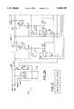
- FIGS. 2A, 2B and 2Care schematic diagrams illustrating the specific embodiment of the battery charger in FIG. 1.
- Battery charger 10includes a power source 14, typically an alternating current voltage source such as, for example, the 110 AC voltage from any electrical outlet common to most buildings.
- the power source 14modifies and rectifies the voltage and then steps it down to a level useable by the battery charger 10 and, subsequently, the load 16 to be powered. These techniques are well known in the art and are left to the skilled artisan for implementation.
- the power sourcemay also be the type used and described in, for example, commonly assigned U.S. patent application Ser. No. 08/080,384, titled Universal Power Converter, filed herewith and herein incorporated by reference for all purposes.
- the power source 14is further connected to a noise filter 18, which is used to filter the power supplied to the battery charger 10 and load 16.
- the power sourceis further connected to various current control circuits 20, 22 and 24, which are used to regulate the current, thus limiting the voltage applied to their respective batteries, 20B, 22B and 24B.
- Each of the current control circuits 20, 22 and 24are further connected to their respective battery 20B, 22B, and 24B.
- the number of control circuitsis determined by the number of battery packs, which can be any number N.
- One current control circuitis provided for each battery pack.
- Each battery 20B, 22B and 24Bis further connected to the load 16, such as, for example, a personal portable computer, a cellular phone, a portable stereo, or any other like electronic device.
- the batteriesmay use non-dissipative charges equalization controls as, for example, described in commonly assigned U.S. patent application Ser. No. 08/080,898, titled Non-Dissipative Battery Charger Equalizer, filed herewith and incorporated by reference for all purposes.
- the power source 14is further connected to a voltage reference 26, which is used to control the current in each current control circuit 20, 22 and 24 and subsequently to control the voltage applied to each battery as charged.
- the power supply 14 intended for use in the battery charger 10is based on a switch mode power supply and is used in conjunction with multiple linear current limiters, which are implemented in the current control circuits 20, 22 and 24.
- Feedback amplifier 28is used in conjunction with the current limiters to operate the switch mode power supply in such a manner as to minimize the voltage output for charging the batteries or operating the system.
- the switch mode power supplyis capable of producing a maximum power required by the system.
- This systemuses two control mechanisms. The first is an input used to control the switch mode power supply output voltage from an external source. This is typically in the form of a voltage that is compared with a reference internal to the switch mode power supply.
- the second mechanismis current limiting within the switch mode supply not controlled by an external source.
- the current limitingis linear and is set at an absolute limit point.
- switch mode power supplymust operate reliably in either the voltage or current modes. This is accomplished by causing the switch mode power supply to limit current in a linear fashion.
- Each current limiter modulethen supplies the charge current to its respective battery.
- the charge currentis monitored and compared to a reference and the resulting error voltage is used to control the output of a series pass element, which obtains its voltage from the switch mode power supply.
- Each battery and current sense devicemay have in parallel a computing device or other electrically powered component and, therefore, the series pass element must be capable of supplying the total of component and battery charging current.
- the switch mode power supplyis not required to continue full rapid charging on all batteries and reduces its output below that which will sustain rapid charge in all batteries, which action is accomplished by the internal current limiter. This diverts the current necessary to supply the power to the demand load momentarily.
- FIG. 2A preferred embodiment of the present invention is illustrated in FIG. 2, which includes FIGS. 2A, 2B and 2C.
- the battery charger 110is connected to a power source, or power supply (not shown), which offers two levels of power for use in the battery charger 110.
- the first level of powercomes in on power main line 128.
- the secondcomes in on power auxiliary line 130.
- the main power line 128supplies around three (3) Amperes (A) of current, which the auxiliary power line 130 supplies 168 mA.
- the main power line 128services the current control circuits 122, 123, 124 for recharging the batteries (not shown).
- the auxiliary power line 130provides operating current for the current control circuitry and substantially follows the main input voltage level.
- a voltage reference element 132which is powered by the auxiliary power line, provides a stable 2.5 volt reference voltage at the cathode of the Schottky Diode U5.
- This voltageis divided by resistor pairs R4-R5, R8-R9, and R12-R13, for current control circuits 122,123, and 124, respectively.
- the reduced referenced voltage from each voltage divider pair R4-R5, R8-R9, and R12-R13is then presented to the inverting inputs of amplifiers U1, U2, and U3, respectively.
- Divider resistors R5, R9, and R13are grounded remotely to the respective battery pack negative terminals, to reduce the effects of current on the power ground circuit.
- Each current control circuit 122, 123, and 124is connected to a respective battery pack (See FIG. 2C) wherein a current output line (OUT) 136A, 136B, and 136C, a current sense (I.SENS) line 138A, 138B, and 138C, a control sense (C.SENS) line 134A, 134B, and 134C, and a ground (GND) line 140A, 140B, and 140C are coupled to the battery pack.
- OUTcurrent output line
- I.SENScurrent sense
- C.SENScontrol sense
- GNDground
- the battery 220 in the battery pack 120is connected between the OUT line 136 and the current sense lines, while a regulating resistor 222 is connected in series with the battery 220 and between the I. SENS. line 138 and the C. SENS. line 134.
- the battery 220 and resistor 222are connected between the OUTput line 136 and the I. SENS. and GND. lines 138 and 140, respectively.
- a resistive load RLOADsuch as a microprocessor of a portable computing device, may be connected in parallel to the battery pack 120.
- the C. SENS. lines 134A, 134B, and 134Care connected to noninverting inputs of each of the current sense amplifiers U1, U2, and U3, respectively.
- Current through a given batteryis then represented as a voltage at the noninverting input of the corresponding current sense amplifier U1, U2, or U3.
- the sensed voltageis then compared with the divided reference voltage to cause the amplifier output to respond in a manner that will control the current through the battery.
- pass transistors Q3, Q5, and Q7which are P-channel MOS field effect transistors (FET), and are connected to the main power line 128 on the source side of the transistor and to the battery on the drain side of the transistor, with the gate being coupled to the output of the current sense amplifiers U1, U2, and U3, respectively.
- Charging currentis controlled by varying the gate voltage to the pass transistor Q3, Q5, and Q7 from the outputs of the current sense amplifiers U1, U2, and U3, respectively, through current shut off transistors Q2, Q4, and Q6, respectively.
- Each current shut off transistor Q2, Q4, and Q6, respectively,is turned off during the absence of input power to prevent the batteries from discharging through resistors R6, R10, and R14, respectively, which resistors are current pull up resistors between the respective gate and source of each pass transistor Q3, Q5, and Q7.
- pass transistors Q3, Q5, and Q7are P-channel MOSFETs, they increase conduction as the gate voltage is made to go increasingly negative with respect to the FET source. As the proper charging current is reached, the output of each current sense amplifier U1, U2, and U3 then increases to provide a gate voltage that maintains the desired current.
- a buffer amplifier U4provides an output voltage to control the main input voltage for each current control circuit 122,123, and 124.
- the connection to amplifier U4is the power to amplifiers U1-U4. As the output voltage decreases, the main supply output voltage is caused to increase.
- the output of buffer amplifier U4is controlled by the lowest signal of all the output signals from current sense amplifiers U1, U2, and U3 through their respective diodes CR1, CR2, and CR3.
- the input to buffer amplifier U4is biased by resistor R15.
- the battery having the highest initial chargewill demand the greatest charging voltage.
- This demandcauses the output of its respective error amplifier to decrease in an effort to increase the output of the corresponding pass transistor Q3, Q5, or Q7.
- Thiscauses a response at the output of buffer amplifier U4 to force the main power supply line 128 to provide the required voltage to the input of the pass transistor Q3, Q5, or Q7 associated with the battery having the greatest charging voltage demand.
- the pass transistor associated with the battery having the greatest charging voltage demandbecomes fully saturated. Via this means, the charging voltage supplied to the controller is held at the minimum voltage required to charge all batteries, thereby reducing the power loss in the main supply and the charge control pass transistors to a minimum.
- Each current control circuit 122, 123, and 124further includes a stabilizing or integrating capacitor C3, C4, and C5, respectively.
- resistor R15serves as a bias resistor for each control diode CR1, CR2, and CR3.
- resistor R16provides a 2.5 volt reference to ground at voltage reference U5.
- Resistor R17is connected between the auxiliary power line and the voltage reference U5 to provided operating current for the 2.5 volts reference.
- eachis mounted on a heat sink to help dissipate the heat generated inside the transistor.
- the circuitry used in this battery charger control circuitmay be implemented in a single integrated chip. Such a chip may be mounted on a single heat sink.
- the pass transistorsmay be integrated together on the same chip but separate from the other elements in each current control circuit. This allows the pass transistors to be mounted to the same heat sink.
- the power dissipated by the series pass elementsdepends on charging/load current multiplied by the voltage across the element. Since current is constant (except for trickle charge), power loss is proportional to series pass voltage. Since minimum series pass voltage is maintained, the worst case power loss quickly becomes quite small as battery voltages equalize. As batteries go into trickle charge, power loss becomes negligible. As batteries become similar in voltage and as each battery reaches a full charge, power dissipation is held at a minimum and is eventually reduced to only that necessary to charge the remaining batteries. Once the batteries are fully charged, a trickle charge of only 45 milliwatts is required to maintain the batteries at a full charge state while the power or battery charger is in operation.
- the power dissipationdoes not reduce gradually in a manner that tracks the power requirements to charge the batteries efficiently, rather, the power dissipation is either at full level, for example, 11 watts, or at a trickle charge state of, for example, 45 milliwatts, with no power variation in between. Accordingly, it is apparent that there is a large amount of power loss associated with the prior battery charging systems that are either on full power or at a trickle charge without any power tracking capabilities as the batteries go from reduced power consumption a full depletion state and full charge state.
- a noise filter 118is provided to filter the voltage before reaching the current control circuits 122, 123, 124.
- the noise filter 118includes a pair of capacitors C1 and C2, which are optimized to provide the best noise filtering capabilities. These two capacitors are connected together in parallel between the auxiliary power line 130 and ground 140.
- a transistor Q1is connected between the auxiliary power line 130 and the power enable line 142 of the power supply, which line 142 is used to turn on monitoring circuits in the battery packs when power is available.
Landscapes
- Engineering & Computer Science (AREA)
- Power Engineering (AREA)
- Physics & Mathematics (AREA)
- General Physics & Mathematics (AREA)
- Charge And Discharge Circuits For Batteries Or The Like (AREA)
Abstract
Description
Claims (8)
Priority Applications (4)
| Application Number | Priority Date | Filing Date | Title |
|---|---|---|---|
| US08/080,272US5486749A (en) | 1993-06-21 | 1993-06-21 | Multiple battery charger with a power source control |
| AU71149/94AAU7114994A (en) | 1993-06-21 | 1994-06-21 | Maximally efficient multiple battery rapid charger/computing device power controller |
| KR1019950705815AKR100210276B1 (en) | 1993-06-21 | 1994-06-21 | Multi-battery quick charger / computing device power controller with maximum efficiency |
| PCT/US1994/007032WO1995000992A1 (en) | 1993-06-21 | 1994-06-21 | Maximally efficient multiple battery rapid charger/computing device power controller |
Applications Claiming Priority (1)
| Application Number | Priority Date | Filing Date | Title |
|---|---|---|---|
| US08/080,272US5486749A (en) | 1993-06-21 | 1993-06-21 | Multiple battery charger with a power source control |
Publications (1)
| Publication Number | Publication Date |
|---|---|
| US5486749Atrue US5486749A (en) | 1996-01-23 |
Family
ID=22156314
Family Applications (1)
| Application Number | Title | Priority Date | Filing Date |
|---|---|---|---|
| US08/080,272Expired - LifetimeUS5486749A (en) | 1993-06-21 | 1993-06-21 | Multiple battery charger with a power source control |
Country Status (4)
| Country | Link |
|---|---|
| US (1) | US5486749A (en) |
| KR (1) | KR100210276B1 (en) |
| AU (1) | AU7114994A (en) |
| WO (1) | WO1995000992A1 (en) |
Cited By (28)
| Publication number | Priority date | Publication date | Assignee | Title |
|---|---|---|---|---|
| US5736831A (en)* | 1996-08-22 | 1998-04-07 | Northrop Grumman Corporation | Power limiting circuit for electric vehicle battery charger |
| US5874823A (en)* | 1996-09-12 | 1999-02-23 | International Business Machines Corporation | Controlled battery charger for charging multiple batteries |
| US5905361A (en)* | 1994-09-01 | 1999-05-18 | Fujitsu Limited | Charging-and-discharging device, constant-voltage and constant-current control circuit, and electronic device |
| DE19904773C1 (en)* | 1999-02-05 | 2000-09-28 | Raimund Wilhelm | Smart nut |
| US6191552B1 (en) | 1999-01-25 | 2001-02-20 | Dell Usa, L.P. | External universal battery charging apparatus and method |
| US6265853B1 (en)* | 1997-11-10 | 2001-07-24 | Tohoku Electric Power Co., Inc. | Power source unit for transferring energy between power sources that power an electric vehicle |
| US20030090234A1 (en)* | 2001-11-09 | 2003-05-15 | Glasgow Kevin L. | Battery charger |
| US20040130295A1 (en)* | 2002-12-21 | 2004-07-08 | Lg Electronics Inc. | Charging system and method for charging a communication terminal |
| US20050024021A1 (en)* | 2003-05-07 | 2005-02-03 | Milwaukee Electric Tool Corporation | Battery charger and assembly |
| US20050110461A1 (en)* | 2000-08-01 | 2005-05-26 | Earthlink Communications | Mobile teaching system |
| US20060113956A1 (en)* | 2003-05-07 | 2006-06-01 | Bublitz Scott D | Battery charger and assembly |
| USD529439S1 (en) | 2002-05-07 | 2006-10-03 | Milwaukee Electric Tool Corporation | Battery charger |
| USD547518S1 (en) | 2005-06-27 | 2007-07-24 | Earthwalk Communications, Inc. | Cart |
| USD555586S1 (en) | 2005-06-27 | 2007-11-20 | Mcconnell Evan T | Battery housing |
| US20090249091A1 (en)* | 2008-03-27 | 2009-10-01 | Goodnow Kenneth J | Secondary power utilization during peak power times |
| US20100201306A1 (en)* | 2007-10-29 | 2010-08-12 | Fujitsu Limited | Charging system, processor and feeder |
| US20120146588A1 (en)* | 2010-12-08 | 2012-06-14 | Yoshihito Ishibashi | Charging control device and charging control method |
| EP2466718A1 (en) | 2010-12-16 | 2012-06-20 | Dialog Semiconductor GmbH | Multiple battery charger with automatic charge current adjustment |
| USD690893S1 (en)* | 2012-06-26 | 2013-10-01 | Cathleen S. O'Brien | Expandable folding cart on wheels |
| US20140117943A1 (en)* | 2011-11-07 | 2014-05-01 | Sony Corporation | Control apparatus and control method |
| FR3029708A1 (en)* | 2014-12-05 | 2016-06-10 | Renault Sa | METHOD AND DEVICE FOR CHARGING A BATTERY OF A MOTOR VEHICLE WITH ELECTRICAL TRACTION LIMITING LOAD LOSSES |
| US9673651B2 (en) | 2013-11-21 | 2017-06-06 | Qualcomm Incorporated | Dynamic voltage adjust circuits and methods |
| WO2019139749A1 (en)* | 2018-01-10 | 2019-07-18 | Microsoft Technology Licensing, Llc | Parallel charging and discharging of batteries with disparate characteristics |
| US10778013B2 (en) | 2018-01-10 | 2020-09-15 | Microsoft Technology Licensing, Llc | Distributed battery architecture |
| US11101680B2 (en) | 2019-06-28 | 2021-08-24 | Microsoft Technology Licensing, Llc | Parallel battery charge management |
| US20210320504A1 (en)* | 2020-04-13 | 2021-10-14 | Samsung Electronics Co., Ltd. | Electronic device for controlling charging of multiple batteries connected in parallel and method for operating same |
| US11165265B2 (en) | 2019-06-28 | 2021-11-02 | Microsoft Technology Licensing, Llc | Parallel battery discharge management |
| US11901749B2 (en) | 2020-09-09 | 2024-02-13 | Microsoft Technology Licensing, Llc | Balanced discharge in multi-battery system |
Families Citing this family (46)
| Publication number | Priority date | Publication date | Assignee | Title |
|---|---|---|---|---|
| JP3571536B2 (en)* | 1997-10-20 | 2004-09-29 | 富士通株式会社 | Battery charging device and method, and electronic device |
| US7183745B2 (en) | 2000-08-11 | 2007-02-27 | Milwaukee Electric Tool Corporation | Adapter for a power tool battery |
| US7443137B2 (en) | 2000-08-11 | 2008-10-28 | Milwaukee Electric Tool Corporation | Adapter for a power tool battery |
| US6525511B2 (en) | 2000-08-11 | 2003-02-25 | Milwaukee Electric Tool Corporation | Adapter for a power tool battery |
| US9530089B2 (en) | 2013-03-04 | 2016-12-27 | Hello Inc. | Wearable device with overlapping ends coupled by magnets of a selected width, length and depth |
| US9357922B2 (en) | 2013-03-04 | 2016-06-07 | Hello Inc. | User or patient monitoring systems with one or more analysis tools |
| US9159223B2 (en) | 2013-03-04 | 2015-10-13 | Hello, Inc. | User monitoring device configured to be in communication with an emergency response system or team |
| US9427160B2 (en) | 2013-03-04 | 2016-08-30 | Hello Inc. | Wearable device with overlapping ends coupled by magnets positioned in the wearable device by an undercut |
| US9339188B2 (en) | 2013-03-04 | 2016-05-17 | James Proud | Methods from monitoring health, wellness and fitness with feedback |
| US9298882B2 (en) | 2013-03-04 | 2016-03-29 | Hello Inc. | Methods using patient monitoring devices with unique patient IDs and a telemetry system |
| US9553486B2 (en) | 2013-03-04 | 2017-01-24 | Hello Inc. | Monitoring system and device with sensors that is remotely powered |
| US9330561B2 (en) | 2013-03-04 | 2016-05-03 | Hello Inc. | Remote communication systems and methods for communicating with a building gateway control to control building systems and elements |
| US9392939B2 (en) | 2013-03-04 | 2016-07-19 | Hello Inc. | Methods using a monitoring device to monitor individual activities, behaviors or habit information and communicate with a database with corresponding individual base information for comparison |
| US9634921B2 (en) | 2013-03-04 | 2017-04-25 | Hello Inc. | Wearable device coupled by magnets positioned in a frame in an interior of the wearable device with at least one electronic circuit |
| US9204798B2 (en) | 2013-03-04 | 2015-12-08 | Hello, Inc. | System for monitoring health, wellness and fitness with feedback |
| US9737214B2 (en) | 2013-03-04 | 2017-08-22 | Hello Inc. | Wireless monitoring of patient exercise and lifestyle |
| US9406220B2 (en) | 2013-03-04 | 2016-08-02 | Hello Inc. | Telemetry system with tracking receiver devices |
| US9430938B2 (en) | 2013-03-04 | 2016-08-30 | Hello Inc. | Monitoring device with selectable wireless communication |
| US9436903B2 (en) | 2013-03-04 | 2016-09-06 | Hello Inc. | Wearable device with magnets with a defined distance between adjacent magnets |
| US9532716B2 (en) | 2013-03-04 | 2017-01-03 | Hello Inc. | Systems using lifestyle database analysis to provide feedback |
| US9662015B2 (en) | 2013-03-04 | 2017-05-30 | Hello Inc. | System or device with wearable devices having one or more sensors with assignment of a wearable device user identifier to a wearable device user |
| US9367793B2 (en) | 2013-03-04 | 2016-06-14 | Hello Inc. | Wearable device with magnets distanced from exterior surfaces of the wearable device |
| US20140246502A1 (en) | 2013-03-04 | 2014-09-04 | Hello Inc. | Wearable devices with magnets encased by a material that redistributes their magnetic fields |
| US9345403B2 (en) | 2013-03-04 | 2016-05-24 | Hello Inc. | Wireless monitoring system with activity manager for monitoring user activity |
| US9398854B2 (en) | 2013-03-04 | 2016-07-26 | Hello Inc. | System with a monitoring device that monitors individual activities, behaviors or habit information and communicates with a database with corresponding individual base information for comparison |
| US9432091B2 (en) | 2013-03-04 | 2016-08-30 | Hello Inc. | Telemetry system with wireless power receiver and monitoring devices |
| US9526422B2 (en) | 2013-03-04 | 2016-12-27 | Hello Inc. | System for monitoring individuals with a monitoring device, telemetry system, activity manager and a feedback system |
| US9320434B2 (en) | 2013-03-04 | 2016-04-26 | Hello Inc. | Patient monitoring systems and messages that send alerts to patients only when the patient is awake |
| US9848776B2 (en) | 2013-03-04 | 2017-12-26 | Hello Inc. | Methods using activity manager for monitoring user activity |
| US9149189B2 (en) | 2013-03-04 | 2015-10-06 | Hello, Inc. | User or patient monitoring methods using one or more analysis tools |
| US9704209B2 (en) | 2013-03-04 | 2017-07-11 | Hello Inc. | Monitoring system and device with sensors and user profiles based on biometric user information |
| US9361572B2 (en) | 2013-03-04 | 2016-06-07 | Hello Inc. | Wearable device with magnets positioned at opposing ends and overlapped from one side to another |
| US9345404B2 (en) | 2013-03-04 | 2016-05-24 | Hello Inc. | Mobile device that monitors an individuals activities, behaviors, habits or health parameters |
| US9445651B2 (en) | 2013-03-04 | 2016-09-20 | Hello Inc. | Wearable device with overlapping ends coupled by magnets |
| US9420857B2 (en) | 2013-03-04 | 2016-08-23 | Hello Inc. | Wearable device with interior frame |
| US9427189B2 (en) | 2013-03-04 | 2016-08-30 | Hello Inc. | Monitoring system and device with sensors that are responsive to skin pigmentation |
| US20130290427A1 (en) | 2013-03-04 | 2013-10-31 | Hello Inc. | Wearable device with unique user ID and telemetry system in communication with one or more social networks |
| US9427053B2 (en) | 2013-03-04 | 2016-08-30 | Hello Inc. | Wearable device with magnets magnetized through their widths or thickness |
| US9424508B2 (en) | 2013-03-04 | 2016-08-23 | Hello Inc. | Wearable device with magnets having first and second polarities |
| US9420856B2 (en) | 2013-03-04 | 2016-08-23 | Hello Inc. | Wearable device with adjacent magnets magnetized in different directions |
| US20160220198A1 (en) | 2013-06-21 | 2016-08-04 | Hello Inc. | Mobile device that monitors an individuals activities, behaviors, habits or health parameters |
| US10004451B1 (en) | 2013-06-21 | 2018-06-26 | Fitbit, Inc. | User monitoring system |
| US9610030B2 (en) | 2015-01-23 | 2017-04-04 | Hello Inc. | Room monitoring device and sleep analysis methods |
| US10009581B2 (en) | 2015-01-02 | 2018-06-26 | Fitbit, Inc. | Room monitoring device |
| US10058290B1 (en) | 2013-06-21 | 2018-08-28 | Fitbit, Inc. | Monitoring device with voice interaction |
| US9993166B1 (en) | 2013-06-21 | 2018-06-12 | Fitbit, Inc. | Monitoring device using radar and measuring motion with a non-contact device |
Citations (16)
| Publication number | Priority date | Publication date | Assignee | Title |
|---|---|---|---|---|
| US4118661A (en)* | 1976-03-24 | 1978-10-03 | British Communications Corporation Limited | Electrical circuit arrangements particularly though not exclusively for electrical battery charging systems |
| US4467264A (en)* | 1979-07-25 | 1984-08-21 | General Electric Company | Battery charger with visual charge indicating means |
| US4614905A (en)* | 1982-10-12 | 1986-09-30 | Telefonaktiebolaget Lm Ericsson | Charging regulator |
| US4670703A (en)* | 1985-05-06 | 1987-06-02 | General Electric Company | Battery charger with three different charging rates |
| US4680528A (en)* | 1985-03-05 | 1987-07-14 | Toko, Inc. | Battery charging device |
| US4792743A (en)* | 1985-11-15 | 1988-12-20 | Sanyo Electric Co., Ltd. | Charging device |
| US4849682A (en)* | 1987-10-30 | 1989-07-18 | Anton/Bauer, Inc. | Battery charging system |
| US4885521A (en)* | 1985-08-26 | 1989-12-05 | Applied Research & Technology, Inc. | Unique computer power system with backup power |
| US5003244A (en)* | 1989-05-09 | 1991-03-26 | Digital Equipment Corporation | Battery charger for charging a plurality of batteries |
| US5028859A (en)* | 1989-06-05 | 1991-07-02 | Motorola, Inc. | Multiple battery, multiple rate battery charger |
| US5153496A (en)* | 1990-09-27 | 1992-10-06 | Baxtrer International Inc. | Cell monitor and control unit for multicell battery |
| US5177425A (en)* | 1988-07-01 | 1993-01-05 | Toyota Jidosha Kabushiki Kaisha | Method of charging and discharging battery and power source apparatus adopting the same |
| US5198743A (en)* | 1990-12-11 | 1993-03-30 | Span, Inc. | Battery charger with microprocessor control |
| US5283512A (en)* | 1992-04-13 | 1994-02-01 | Hughes Aircraft Company | Charge balancing of batteries during charging |
| US5371454A (en)* | 1993-03-08 | 1994-12-06 | Marek; Albert | Passive battery charging system |
| US5422558A (en)* | 1993-05-05 | 1995-06-06 | Astec International Ltd. | Multicell battery power system |
- 1993
- 1993-06-21USUS08/080,272patent/US5486749A/ennot_activeExpired - Lifetime
- 1994
- 1994-06-21KRKR1019950705815Apatent/KR100210276B1/ennot_activeExpired - Fee Related
- 1994-06-21AUAU71149/94Apatent/AU7114994A/ennot_activeAbandoned
- 1994-06-21WOPCT/US1994/007032patent/WO1995000992A1/enactiveApplication Filing
Patent Citations (16)
| Publication number | Priority date | Publication date | Assignee | Title |
|---|---|---|---|---|
| US4118661A (en)* | 1976-03-24 | 1978-10-03 | British Communications Corporation Limited | Electrical circuit arrangements particularly though not exclusively for electrical battery charging systems |
| US4467264A (en)* | 1979-07-25 | 1984-08-21 | General Electric Company | Battery charger with visual charge indicating means |
| US4614905A (en)* | 1982-10-12 | 1986-09-30 | Telefonaktiebolaget Lm Ericsson | Charging regulator |
| US4680528A (en)* | 1985-03-05 | 1987-07-14 | Toko, Inc. | Battery charging device |
| US4670703A (en)* | 1985-05-06 | 1987-06-02 | General Electric Company | Battery charger with three different charging rates |
| US4885521A (en)* | 1985-08-26 | 1989-12-05 | Applied Research & Technology, Inc. | Unique computer power system with backup power |
| US4792743A (en)* | 1985-11-15 | 1988-12-20 | Sanyo Electric Co., Ltd. | Charging device |
| US4849682A (en)* | 1987-10-30 | 1989-07-18 | Anton/Bauer, Inc. | Battery charging system |
| US5177425A (en)* | 1988-07-01 | 1993-01-05 | Toyota Jidosha Kabushiki Kaisha | Method of charging and discharging battery and power source apparatus adopting the same |
| US5003244A (en)* | 1989-05-09 | 1991-03-26 | Digital Equipment Corporation | Battery charger for charging a plurality of batteries |
| US5028859A (en)* | 1989-06-05 | 1991-07-02 | Motorola, Inc. | Multiple battery, multiple rate battery charger |
| US5153496A (en)* | 1990-09-27 | 1992-10-06 | Baxtrer International Inc. | Cell monitor and control unit for multicell battery |
| US5198743A (en)* | 1990-12-11 | 1993-03-30 | Span, Inc. | Battery charger with microprocessor control |
| US5283512A (en)* | 1992-04-13 | 1994-02-01 | Hughes Aircraft Company | Charge balancing of batteries during charging |
| US5371454A (en)* | 1993-03-08 | 1994-12-06 | Marek; Albert | Passive battery charging system |
| US5422558A (en)* | 1993-05-05 | 1995-06-06 | Astec International Ltd. | Multicell battery power system |
Cited By (41)
| Publication number | Priority date | Publication date | Assignee | Title |
|---|---|---|---|---|
| US5905361A (en)* | 1994-09-01 | 1999-05-18 | Fujitsu Limited | Charging-and-discharging device, constant-voltage and constant-current control circuit, and electronic device |
| US5736831A (en)* | 1996-08-22 | 1998-04-07 | Northrop Grumman Corporation | Power limiting circuit for electric vehicle battery charger |
| US5874823A (en)* | 1996-09-12 | 1999-02-23 | International Business Machines Corporation | Controlled battery charger for charging multiple batteries |
| US6265853B1 (en)* | 1997-11-10 | 2001-07-24 | Tohoku Electric Power Co., Inc. | Power source unit for transferring energy between power sources that power an electric vehicle |
| US6191552B1 (en) | 1999-01-25 | 2001-02-20 | Dell Usa, L.P. | External universal battery charging apparatus and method |
| US6337557B1 (en) | 1999-01-25 | 2002-01-08 | Barry K. Kates | External universal battery charging apparatus and method |
| DE19904773C1 (en)* | 1999-02-05 | 2000-09-28 | Raimund Wilhelm | Smart nut |
| US20050110461A1 (en)* | 2000-08-01 | 2005-05-26 | Earthlink Communications | Mobile teaching system |
| US7160113B2 (en) | 2000-08-01 | 2007-01-09 | Earthwalk Communication, Inc. | Mobile teaching system |
| US7332889B2 (en) | 2001-11-09 | 2008-02-19 | Milwaukee Electric Tool Corporation | Battery charger |
| US20030090234A1 (en)* | 2001-11-09 | 2003-05-15 | Glasgow Kevin L. | Battery charger |
| US20080100261A1 (en)* | 2001-11-09 | 2008-05-01 | Glasgow Kevin L | Battery charger |
| USD529439S1 (en) | 2002-05-07 | 2006-10-03 | Milwaukee Electric Tool Corporation | Battery charger |
| US20040130295A1 (en)* | 2002-12-21 | 2004-07-08 | Lg Electronics Inc. | Charging system and method for charging a communication terminal |
| US7355366B2 (en)* | 2002-12-21 | 2008-04-08 | Lg Electronics Inc. | Charging system and method for charging a communication terminal |
| US20060113956A1 (en)* | 2003-05-07 | 2006-06-01 | Bublitz Scott D | Battery charger and assembly |
| US20080036420A1 (en)* | 2003-05-07 | 2008-02-14 | Zeiler Jeffrey M | Battery charger and assembly |
| US20050024021A1 (en)* | 2003-05-07 | 2005-02-03 | Milwaukee Electric Tool Corporation | Battery charger and assembly |
| US7659696B2 (en) | 2003-05-07 | 2010-02-09 | Milwaukee Electric Tool Corporation | Battery charger and assembly |
| USD555586S1 (en) | 2005-06-27 | 2007-11-20 | Mcconnell Evan T | Battery housing |
| USD547518S1 (en) | 2005-06-27 | 2007-07-24 | Earthwalk Communications, Inc. | Cart |
| US8324866B2 (en)* | 2007-10-29 | 2012-12-04 | Fujitsu Limited | Charging system, processor and feeder |
| US20100201306A1 (en)* | 2007-10-29 | 2010-08-12 | Fujitsu Limited | Charging system, processor and feeder |
| US20090249091A1 (en)* | 2008-03-27 | 2009-10-01 | Goodnow Kenneth J | Secondary power utilization during peak power times |
| US8301921B2 (en) | 2008-03-27 | 2012-10-30 | International Business Machines Corporation | Secondary power utilization during peak power times |
| US8549335B2 (en) | 2008-03-27 | 2013-10-01 | International Business Machines Corporation | Secondary power utilization during peak power times |
| US20120146588A1 (en)* | 2010-12-08 | 2012-06-14 | Yoshihito Ishibashi | Charging control device and charging control method |
| US9755440B2 (en)* | 2010-12-08 | 2017-09-05 | Sony Corporation | Charging control device and charging control method |
| EP2466718A1 (en) | 2010-12-16 | 2012-06-20 | Dialog Semiconductor GmbH | Multiple battery charger with automatic charge current adjustment |
| US20140117943A1 (en)* | 2011-11-07 | 2014-05-01 | Sony Corporation | Control apparatus and control method |
| US9257861B2 (en)* | 2011-11-07 | 2016-02-09 | Sony Corporation | Control apparatus and control method |
| USD690893S1 (en)* | 2012-06-26 | 2013-10-01 | Cathleen S. O'Brien | Expandable folding cart on wheels |
| US9673651B2 (en) | 2013-11-21 | 2017-06-06 | Qualcomm Incorporated | Dynamic voltage adjust circuits and methods |
| FR3029708A1 (en)* | 2014-12-05 | 2016-06-10 | Renault Sa | METHOD AND DEVICE FOR CHARGING A BATTERY OF A MOTOR VEHICLE WITH ELECTRICAL TRACTION LIMITING LOAD LOSSES |
| WO2019139749A1 (en)* | 2018-01-10 | 2019-07-18 | Microsoft Technology Licensing, Llc | Parallel charging and discharging of batteries with disparate characteristics |
| US10778013B2 (en) | 2018-01-10 | 2020-09-15 | Microsoft Technology Licensing, Llc | Distributed battery architecture |
| US11101680B2 (en) | 2019-06-28 | 2021-08-24 | Microsoft Technology Licensing, Llc | Parallel battery charge management |
| US11165265B2 (en) | 2019-06-28 | 2021-11-02 | Microsoft Technology Licensing, Llc | Parallel battery discharge management |
| US11742690B2 (en) | 2019-06-28 | 2023-08-29 | Microsoft Technology Licensing, Llc | Parallel battery charge management |
| US20210320504A1 (en)* | 2020-04-13 | 2021-10-14 | Samsung Electronics Co., Ltd. | Electronic device for controlling charging of multiple batteries connected in parallel and method for operating same |
| US11901749B2 (en) | 2020-09-09 | 2024-02-13 | Microsoft Technology Licensing, Llc | Balanced discharge in multi-battery system |
Also Published As
| Publication number | Publication date |
|---|---|
| KR960703283A (en) | 1996-06-19 |
| AU7114994A (en) | 1995-01-17 |
| KR100210276B1 (en) | 1999-07-15 |
| WO1995000992A1 (en) | 1995-01-05 |
Similar Documents
| Publication | Publication Date | Title |
|---|---|---|
| US5486749A (en) | Multiple battery charger with a power source control | |
| US6300744B1 (en) | High-efficiency battery charger | |
| US11677260B2 (en) | Managing power in a portable device comprising multiple batteries | |
| US5672952A (en) | Controller for battery charger with reduced reverse leakage current | |
| US11955821B2 (en) | Managing power in a portable device comprising multiple batteries | |
| KR101060052B1 (en) | Voltage converter with combined buck converter and capacitive voltage divider | |
| US12160125B2 (en) | Charging integrated circuit for charging battery device and electronic device including the same | |
| KR101041730B1 (en) | Voltage converter with combined capacitive voltage divider, buck converter and battery charger | |
| US7602158B1 (en) | Power circuit for generating non-isolated low voltage power in a standby condition | |
| CA2632898C (en) | Charging and power supply for mobile devices | |
| US8035350B2 (en) | Battery charger | |
| CN100544098C (en) | Charging circuit, method of controlling operation of charging circuit, and power supply unit | |
| US6861824B1 (en) | Charger system with dual-level current regulation and dual-level thermal regulation | |
| US20160072331A1 (en) | Method for limiting battery discharging current in battery charger and discharger circuit | |
| US20070114849A1 (en) | Electrical load with preferential source | |
| US20100231047A1 (en) | Power safety system | |
| JPH1014127A (en) | Multifunctional battery charger self-aligns as a supply voltage regulator for battery powered devices | |
| US11387667B2 (en) | Combo buck boost battery charger architecture with reverse boost mode | |
| US6157173A (en) | Circuit and method for sharing current between a portable device and a battery charger | |
| GB2416606A (en) | Power supply circuit for portable battery powered device | |
| JP4126329B2 (en) | Electronic device, charging device, charging control circuit, and charging control method | |
| US5045768A (en) | Off-line battery charger | |
| JP2002320338A (en) | Adjusting device of voltage supplied from battery | |
| US7880443B2 (en) | System and method of trickle charging a battery in a narrow rail architecture | |
| US7701178B2 (en) | Charge control that keeps constant input voltage supplied to battery pack |
Legal Events
| Date | Code | Title | Description |
|---|---|---|---|
| AS | Assignment | Owner name:TANDY CORPORATION Free format text:ASSIGNMENT OF ASSIGNORS INTEREST;ASSIGNOR:BRAINARD, GERALD L.;REEL/FRAME:006586/0796 Effective date:19930618 | |
| AS | Assignment | Owner name:AST RESEARCH, INC., CALIFORNIA Free format text:ASSIGNMENT OF ASSIGNORS INTEREST;ASSIGNOR:TANDY CORPORATION AND ITS RADIO SHACK DIVISION;REEL/FRAME:006847/0109 Effective date:19940103 | |
| STPP | Information on status: patent application and granting procedure in general | Free format text:APPLICATION UNDERGOING PREEXAM PROCESSING | |
| AS | Assignment | Owner name:AST RESEARCH, INC., CALIFORNIA Free format text:SECURITY INTEREST;ASSIGNOR:AST COMPUTERS, LLC;REEL/FRAME:009703/0089 Effective date:19990108 | |
| FPAY | Fee payment | Year of fee payment:4 | |
| AS | Assignment | Owner name:SAMSUNG ELECTRONICS AMERICA, INC., NEW JERSEY Free format text:ASSIGNMENT OF ASSIGNORS INTEREST;ASSIGNOR:ARI SERVICE, INC.;REEL/FRAME:012665/0878 Effective date:20020318 Owner name:ARI SERVICE, INC., CALIFORNIA Free format text:AGREEMENT OF MERGER AST RESEARCH, INC., WITH AND INTO ARI SERVICE, INC.;ASSIGNORS:AST RESEARCH, INC., A DELAWARE CORPORATION;ARI SERVICE, INC., A CALIFORNIA CORPORATION;REEL/FRAME:012691/0384 Effective date:20000330 | |
| AS | Assignment | Owner name:SAMSUNG ELECTRONICS CO., LTD., KOREA, REPUBLIC OF Free format text:ASSIGNMENT OF ASSIGNORS INTEREST;ASSIGNOR:SAMSUNG ELECTRONICS AMERICA, INC.;REEL/FRAME:012721/0141 Effective date:20020326 | |
| AS | Assignment | Owner name:AST COMPUTERS, LLC, CALIFORNIA Free format text:RELEASE OF SECURITY INTEREST;ASSIGNOR:ARI SERVICE, INC., AS SUCCESSOR IN INTEREST BY MERGER TO AST RESEARCH, INC.;REEL/FRAME:012852/0320 Effective date:20020503 | |
| FEPP | Fee payment procedure | Free format text:PAYOR NUMBER ASSIGNED (ORIGINAL EVENT CODE: ASPN); ENTITY STATUS OF PATENT OWNER: LARGE ENTITY | |
| FPAY | Fee payment | Year of fee payment:8 | |
| FPAY | Fee payment | Year of fee payment:12 |