US5486177A - Patella planer with adjustable stop - Google Patents
Patella planer with adjustable stopDownload PDFInfo
- Publication number
- US5486177A US5486177AUS08/359,873US35987394AUS5486177AUS 5486177 AUS5486177 AUS 5486177AUS 35987394 AUS35987394 AUS 35987394AUS 5486177 AUS5486177 AUS 5486177A
- Authority
- US
- United States
- Prior art keywords
- patella
- selecting
- cut
- surgical apparatus
- clamp
- Prior art date
- Legal status (The legal status is an assumption and is not a legal conclusion. Google has not performed a legal analysis and makes no representation as to the accuracy of the status listed.)
- Expired - Lifetime
Links
- 210000004417patellaAnatomy0.000titleclaimsabstractdescription60
- 239000007943implantSubstances0.000claims1
- 210000003127kneeAnatomy0.000abstractdescription14
- 210000003813thumbAnatomy0.000description4
- 230000000399orthopedic effectEffects0.000description3
- 210000002303tibiaAnatomy0.000description3
- 210000000689upper legAnatomy0.000description3
- 238000001356surgical procedureMethods0.000description2
- 210000000988bone and boneAnatomy0.000description1
- 230000006835compressionEffects0.000description1
- 238000007906compressionMethods0.000description1
- 238000002271resectionMethods0.000description1
- 230000000717retained effectEffects0.000description1
Images


Classifications
- A—HUMAN NECESSITIES
- A61—MEDICAL OR VETERINARY SCIENCE; HYGIENE
- A61B—DIAGNOSIS; SURGERY; IDENTIFICATION
- A61B17/00—Surgical instruments, devices or methods
- A61B17/16—Instruments for performing osteoclasis; Drills or chisels for bones; Trepans
- A61B17/1662—Instruments for performing osteoclasis; Drills or chisels for bones; Trepans for particular parts of the body
- A61B17/1675—Instruments for performing osteoclasis; Drills or chisels for bones; Trepans for particular parts of the body for the knee
- A61B17/1677—Instruments for performing osteoclasis; Drills or chisels for bones; Trepans for particular parts of the body for the knee for the patella
- A—HUMAN NECESSITIES
- A61—MEDICAL OR VETERINARY SCIENCE; HYGIENE
- A61B—DIAGNOSIS; SURGERY; IDENTIFICATION
- A61B17/00—Surgical instruments, devices or methods
- A61B17/16—Instruments for performing osteoclasis; Drills or chisels for bones; Trepans
- A61B17/17—Guides or aligning means for drills, mills, pins or wires
- A61B17/1739—Guides or aligning means for drills, mills, pins or wires specially adapted for particular parts of the body
- A61B17/1764—Guides or aligning means for drills, mills, pins or wires specially adapted for particular parts of the body for the knee
- A61B17/1767—Guides or aligning means for drills, mills, pins or wires specially adapted for particular parts of the body for the knee for the patella
- A—HUMAN NECESSITIES
- A61—MEDICAL OR VETERINARY SCIENCE; HYGIENE
- A61B—DIAGNOSIS; SURGERY; IDENTIFICATION
- A61B17/00—Surgical instruments, devices or methods
- A61B17/16—Instruments for performing osteoclasis; Drills or chisels for bones; Trepans
- A61B2017/1602—Mills
- A—HUMAN NECESSITIES
- A61—MEDICAL OR VETERINARY SCIENCE; HYGIENE
- A61B—DIAGNOSIS; SURGERY; IDENTIFICATION
- A61B90/00—Instruments, implements or accessories specially adapted for surgery or diagnosis and not covered by any of the groups A61B1/00 - A61B50/00, e.g. for luxation treatment or for protecting wound edges
- A61B90/03—Automatic limiting or abutting means, e.g. for safety
- A61B2090/033—Abutting means, stops, e.g. abutting on tissue or skin
- Y—GENERAL TAGGING OF NEW TECHNOLOGICAL DEVELOPMENTS; GENERAL TAGGING OF CROSS-SECTIONAL TECHNOLOGIES SPANNING OVER SEVERAL SECTIONS OF THE IPC; TECHNICAL SUBJECTS COVERED BY FORMER USPC CROSS-REFERENCE ART COLLECTIONS [XRACs] AND DIGESTS
- Y10—TECHNICAL SUBJECTS COVERED BY FORMER USPC
- Y10T—TECHNICAL SUBJECTS COVERED BY FORMER US CLASSIFICATION
- Y10T408/00—Cutting by use of rotating axially moving tool
- Y10T408/55—Cutting by use of rotating axially moving tool with work-engaging structure other than Tool or tool-support
- Y10T408/567—Adjustable, tool-guiding jig
- Y—GENERAL TAGGING OF NEW TECHNOLOGICAL DEVELOPMENTS; GENERAL TAGGING OF CROSS-SECTIONAL TECHNOLOGIES SPANNING OVER SEVERAL SECTIONS OF THE IPC; TECHNICAL SUBJECTS COVERED BY FORMER USPC CROSS-REFERENCE ART COLLECTIONS [XRACs] AND DIGESTS
- Y10—TECHNICAL SUBJECTS COVERED BY FORMER USPC
- Y10T—TECHNICAL SUBJECTS COVERED BY FORMER US CLASSIFICATION
- Y10T408/00—Cutting by use of rotating axially moving tool
- Y10T408/96—Miscellaneous
- Y10T408/99—Adjustable stop
Definitions
- Our inventionrelates to apparatus for surgery, and particularly for orthopedic surgery related to the knee, and most specifically to apparatus for preparing the patella to receive an artificial surface which would cooperate with a implanted prosthetic knee having femoral and tibial components.
- Orthopedic prosthetic kneesare available from many manufacturers, including Intermedics Orthopedics, Inc., the assignee of our present invention.
- Such prosthetic kneestypically comprise a tibial component and a femoral component.
- the tibial componentreplaces the condyle compartments on the proximal end of a patient's tibia.
- the femoral componentreplaces the distal end of the patient's femur and provides artificial condyles which articulate with the condyle compartments of the prosthetic tibial component.
- the patellarides between the condyles of the knee and provides an attachment point for various tenons.
- a portion of the patellamust be cut away and a surface prepared to receive the prosthesis.
- Various surgical apparatus and deviceshave been proposed to accurately and replicably assist in this operation.
- a patella planeris described by Smith & Nephew Richards, Inc. in connection with their Genesis (tm) Total Knee System.
- Another type of planerhas been described and sold by Biomet, Inc. in connection with their AGC (tm) Total Knee System.
- an apparatushas also been provided by Dow Corning Wright Company for use with the Whiteside Ortholoc (tm) Modular Knee System.
- Johnson & Johnsonhas sold a device for preparing the patella in connection with the PFC (tm) Knee System.
- planerIn general, however, although a planer is employed with each of these systems, the planer has generally been used to finish the surface of the patella. A preliminary resection with a sagittal saw has been necessary to prepare the patella before planing. In many cases this has been necessary because of the variation in physiologic thickness of a patella from patient to patient.
- a patella planerwhich can be used in a single operation to produce a resected surface on a patella, suitable for receiving an artificial prosthetic patella.
- Another important object of our inventionhas been to provide a patella planer which would stop cutting at a desired depth of cut, irrespective of the initial thickness of the patella.
- a patella planerwhich permits a resected surface to be prepared on a patella in a single operation.
- an adjustable stopwhich can be used on either side of the planer so that the planer may be used on the right or left knee.
- the adjustable stophas a floating zero pointer which can be set to accommodate varying thickness of the patient's patella.
- the amount of patella material to be removedcan be selected by adjusting an offset stop pin.
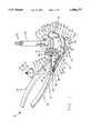
- FIG. 1is a prospective view of a patella planer according to our invention.
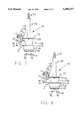
- FIG. 2is a prospective view of an adjustable stop for use with the planer of FIG. 1.
- FIG. 3is an exploded prospective view of the adjustable stop of FIG. 2.
- FIG. 4is a top plan view of the adjustable stop of FIG. 2.
- FIG. 5is a side plan view of the adjustable stop of FIG. 2.
- FIG. 6is a through section of the adjustable stop taken along line 6--6 of FIG. 4.
- FIG. 7is a front plan view of the patella planer.
- FIG. 8is also a front plan view of the patella planer.
- FIG. 1illustrates a perspective view of a patella planer, generally designated 10, according to our invention.
- the planer 10comprises a parallel jaw clamp 12 which is adapted to support the patient's patella and to guide a cutter 14.
- the cutter 14When connected to a source of torsional power, the cutter 14 can plane away a portion of the patella.
- a suitable cutteris available from Othy Inc. of Warsaw, Ind.
- the depth of cut of the cutter 14 into the patellais controlled by a planer stop 16.
- the planer stop 16can be adjusted to accommodate any patella thickness and to provide one or more selected depths of cut, as will be more particularly described hereafter.
- the parallel jaw clamp 12comprises two handles 18, 20 pivotally joined at a central pin 22.
- a threaded rod 24connects the lower handle 20 to the upper handle 18.
- a distal end 26 of the rod 24is pinned with a press fit pin 28 to the lower handle 20.
- the rod 24passes through a slot 30 in the upper handle.
- a lock nut 32 on the threaded rodtightens against the upper handle 18 to hold parallel jaw clamp 12 in a desired position against the patella.
- Attached to the handles 18,20are upper and lower arms 38,40 respectively.
- the arms 38,40are connected to the handles so that they will close in the parallel faction.
- the lower arm 40is connected to a distal end 42 of the upper handle 18 by a pivoting pin 44.
- the lower arm 40is also connected to the lower handle 20 by a pin 46 which rides in a slot 48 in the arm 40.
- the upper arm 38is similarly connected to a distal end 50 of the lower handle 20 and to the upper handle 18 by a pin 52.
- the lower arm 40supports a base plate 54.
- the base platehas a plurality of spikes 56 on an upper side 58 thereof.
- the patient's patellais laid with an anterior side (that is, the side of the patella which does not articulate against the femur and tibia) against the spikes 56 on the base plate 54.
- Above the base plate 54is a guide ring 60 which is connected to the upper arm 38.
- the guide ring 60is essentially an annular body having circumferential teeth 62 on a lower edge 64 thereof. The teeth 62 press against the posterior side of the patella, that is, against the side which articulates against the femur and tibia.
- the cutter 14passes through the guide ring 60 to act against the posterior side of the patient's patella.
- the guide ring 60has a lip 66 at an upper edge 68.
- a removable support ring 70rides on the lip 66.
- the support ring 70has a right platform 72 and a left platform 74 on opposite sides of the support ring 70.
- the platforms 72,74have bayonet locks 76,78 respectively so that the support ring 70 can be securely attached to the lip 66.
- two bores 80, 82are provided for the attachment of the planer stop 16, as will be more particularly described below.
- the planer stop 16is shown most clearly in FIGS. 2 through 6.
- the planer stop 16comprises a housing 84 having a longitudinal tongue 86 on an upper side 88 thereof.
- a support bar 90has a longitudinal groove 92 which fits over the tongue 86.
- the support bar 90also has a longitudinal slot 94 which exposes a top surface 96 of the tongue 86.
- Two mounting pins 98, 100fixed to a distal end 102 of the support bar 90, fit into the bores 82 on the platform of the support ring 70.
- the planer stop 16can, therefore, be placed on either the right or the left platform as needed to accommodate the particular situation confronting the surgeon.
- Two bores 104, 106are provided in the tongue 86 of the housing 84.
- a partially threaded shaft 108is press fit.
- Proximal threads 110pass through the slot 94 in the support bar 90 and receive a thumb nut 112.
- the thumb nut 112is retained on the partially threaded shaft 108 by a transverse pin 115. Tightening the thumb nut 112 against the support bar 90 locks the housing 84 in a selected position along the support bar.
- a floating zero pointer 114is press fit. The function of this pointer will be more particularly explained hereafter.
- the housing 84also supports an offset stop pin 116.
- the stop pin 116has a shaft 118 which passes loosely through a bore 120 in the housing 84.
- the shaft 118also passes through the slot 94 in the support bar 90.
- a bearing surface 124which supports a compression spring 126 within the housing 84.
- Attached to the bearing 124is a stop shaft 128.
- the shaft 118defines a longitudinal axis and the stop shaft 128 defines a second longitudinal axis. These two axes are parallel to one another but are offset eccentrically.
- a handle 132is attached to the stop pin 116.
- the handle 132has a grip 134 and a hollow shaft 136 which fits over the shaft 118.
- a pin 138connects the handle 132 to the shaft 118.
- one or more index tabs 142may be provided at a distal end 140 of the hollow shaft 136. These tabs 142 fit into index recesses 144 in the housing 84.
- the spring 126normally urges the handle 132 against the housing 84, thus pressing the index tabs 142 into the index recesses 144.
- the index tabs 142can be disengaged from their associated recess 144 and the stop pin 116 can be rotated. This rotation selects the position of the stop shaft 128 with respect to the floating zero pointer 114.
- the cutter 14is a commercially available surgical cutter or planer.
- such cutters 14have a drive shaft 150 with a connection 152 proximally for attachment to as source of torsional power.
- a latch 154connects a planer housing 155 to the drive shaft 150.
- the planer housing 155has a cylindrical cup 156 which has cutting elements (not shown) oriented to abut the patella. Bone chips are scraped off the patella by the rotary motion of the cutter 14 and are captured within the cup 156.
- the planer housing 155has a circumferential flange 158. In our preferred embodiment, this flange 158 is utilized both to adjust the position of the housing 84 and to engage the stop shaft 128 on the offset stop pin 116, preventing further cutting into the patella.
- the patella of the patientis placed on the base plate 54.
- the guide ring 60is then lowered against the posterior side of the patella and the handles 18, 20 are locked with the lock nut 32.
- the support ring 70is placed on the guide ring 60.
- the cutter 14is placed into the guide ring 60 and advanced until it rests against the posterior side of the patella.
- the planer stop 16is then placed on the selected platform 74.
- the housing 84is moved along the support bar 90 until the floating zero pointer 114 aligns with the flange 158 on the cutter 14, as illustrated in FIG. 7.
- the thumb nut 112is then tightened to secure the housing 84 in its selected location.
- the offset pin 116is then rotated to a selected position to select the depth of cut.
- the stop shaft 128oriented proximally away from the patella, a depth of cut of about seven millimeters would be selected. With the stop pin 116 rotated 180 degrees, the stop shaft 128 would be closer to the patella and the depth of cut would be approximately ten millimeters. Once the depth of cut has been selected, the cutter 14 can be driven to plane away a surface on the patella until the flange 158 contacts the stop 128, as illustrated in FIG. 8.
Landscapes
- Health & Medical Sciences (AREA)
- Surgery (AREA)
- Life Sciences & Earth Sciences (AREA)
- Biomedical Technology (AREA)
- Medical Informatics (AREA)
- Orthopedic Medicine & Surgery (AREA)
- Oral & Maxillofacial Surgery (AREA)
- Engineering & Computer Science (AREA)
- Dentistry (AREA)
- Heart & Thoracic Surgery (AREA)
- Nuclear Medicine, Radiotherapy & Molecular Imaging (AREA)
- Molecular Biology (AREA)
- Animal Behavior & Ethology (AREA)
- General Health & Medical Sciences (AREA)
- Public Health (AREA)
- Veterinary Medicine (AREA)
- Prostheses (AREA)
- Surgical Instruments (AREA)
Abstract
Description
Claims (14)
Priority Applications (2)
| Application Number | Priority Date | Filing Date | Title |
|---|---|---|---|
| US08/359,873US5486177A (en) | 1994-12-20 | 1994-12-20 | Patella planer with adjustable stop |
| PCT/US1995/015709WO1996019147A1 (en) | 1994-12-20 | 1995-12-04 | Patella planer with adjustable stop |
Applications Claiming Priority (1)
| Application Number | Priority Date | Filing Date | Title |
|---|---|---|---|
| US08/359,873US5486177A (en) | 1994-12-20 | 1994-12-20 | Patella planer with adjustable stop |
Publications (1)
| Publication Number | Publication Date |
|---|---|
| US5486177Atrue US5486177A (en) | 1996-01-23 |
Family
ID=23415648
Family Applications (1)
| Application Number | Title | Priority Date | Filing Date |
|---|---|---|---|
| US08/359,873Expired - LifetimeUS5486177A (en) | 1994-12-20 | 1994-12-20 | Patella planer with adjustable stop |
Country Status (2)
| Country | Link |
|---|---|
| US (1) | US5486177A (en) |
| WO (1) | WO1996019147A1 (en) |
Cited By (36)
| Publication number | Priority date | Publication date | Assignee | Title |
|---|---|---|---|---|
| US5658291A (en)* | 1995-09-29 | 1997-08-19 | Johnson & Johnson Medical, Inc. | Median ridge referencing patella cutting system |
| EP0791335A1 (en) | 1996-02-20 | 1997-08-27 | Howmedica Inc. | Patella milling instrument |
| US5667512A (en)* | 1996-05-03 | 1997-09-16 | Metagen, Llc | Patellar resection guide |
| US5716360A (en)* | 1995-06-30 | 1998-02-10 | U.S. Medical Products | Patella recession instrument and method for anatomically-shaped patellar prostheses |
| US5941884A (en)* | 1998-10-09 | 1999-08-24 | Osteonics Corp. | Patella preparation apparatus and method |
| US5947664A (en)* | 1997-09-15 | 1999-09-07 | Espinosa; Gil | Stop device for use with milling machines |
| US5976143A (en)* | 1997-12-23 | 1999-11-02 | Johnson & Johnson Professional, Inc. | Orthopedic reaming instrument |
| US6120507A (en)* | 1999-01-29 | 2000-09-19 | Bristol-Myers Squibb Company | Instrument and method for seating prosthesis |
| US6221087B1 (en)* | 1999-10-01 | 2001-04-24 | Scimed Life Systems, Inc. | Ablation assembly with safety stop |
| US20040087961A1 (en)* | 2002-09-03 | 2004-05-06 | Wood Steven R. | Patellar milling clamp |
| US20040162561A1 (en)* | 2003-02-13 | 2004-08-19 | Howmedica Osteonics Corp. | Modular patella instrument |
| US20050021044A1 (en)* | 2003-06-09 | 2005-01-27 | Vitruvian Orthopaedics, Llc | Surgical orientation device and method |
| US6855150B1 (en) | 2001-07-13 | 2005-02-15 | Timothy R. Linehan | Patellar trial and drill guide for use in knee replacement surgery |
| US20050228398A1 (en)* | 2004-04-12 | 2005-10-13 | Rathbun David S | Free hand drill guide |
| US20050256527A1 (en)* | 2002-04-08 | 2005-11-17 | Daniel Delfosse | Ligament tensioning device with cutting jig, and osteotomy method |
| US20060155295A1 (en)* | 2002-07-05 | 2006-07-13 | Walter Supper | Ligament tensing device with displaceable lug |
| US20060155380A1 (en)* | 2002-10-23 | 2006-07-13 | Mako Surgical Corporation | Modular femoral component for a total knee joint replacement for minimally invasive implantation |
| US20080097450A1 (en)* | 2006-09-14 | 2008-04-24 | Zimmer Technology, Inc. | Patella clamp |
| US20080300689A1 (en)* | 2006-01-23 | 2008-12-04 | Mc Kinnon Brian W | Patellar Components |
| US7559931B2 (en) | 2003-06-09 | 2009-07-14 | OrthAlign, Inc. | Surgical orientation system and method |
| US7632279B2 (en) | 2004-12-27 | 2009-12-15 | Howmedica Osteonics Corp. | Patella resection clamp |
| US20100063508A1 (en)* | 2008-07-24 | 2010-03-11 | OrthAlign, Inc. | Systems and methods for joint replacement |
| US20100160915A1 (en)* | 2006-10-18 | 2010-06-24 | Howmedica Osteonics Corp. | Mis patellar preparation |
| US20110208093A1 (en)* | 2010-01-21 | 2011-08-25 | OrthAlign, Inc. | Systems and methods for joint replacement |
| US20110218543A1 (en)* | 2009-07-24 | 2011-09-08 | OrthAlign, Inc. | Systems and methods for joint replacement |
| US8728087B2 (en) | 2010-10-13 | 2014-05-20 | Howmedica Osteonics Corp. | Automatically adjusting patella cutting guide |
| US8945135B2 (en) | 2011-02-14 | 2015-02-03 | Michael D. Ries | Patellar prostheses and instrumentation |
| US8974468B2 (en) | 2008-09-10 | 2015-03-10 | OrthAlign, Inc. | Hip surgery systems and methods |
| US9192459B2 (en) | 2000-01-14 | 2015-11-24 | Bonutti Skeletal Innovations Llc | Method of performing total knee arthroplasty |
| US9549742B2 (en) | 2012-05-18 | 2017-01-24 | OrthAlign, Inc. | Devices and methods for knee arthroplasty |
| US9649160B2 (en) | 2012-08-14 | 2017-05-16 | OrthAlign, Inc. | Hip replacement navigation system and method |
| US9675399B2 (en) | 2011-02-14 | 2017-06-13 | Michael D. Ries | Patient specific implants and instrumentation for patellar prostheses |
| US10363149B2 (en) | 2015-02-20 | 2019-07-30 | OrthAlign, Inc. | Hip replacement navigation system and method |
| US10863995B2 (en) | 2017-03-14 | 2020-12-15 | OrthAlign, Inc. | Soft tissue measurement and balancing systems and methods |
| US10869771B2 (en) | 2009-07-24 | 2020-12-22 | OrthAlign, Inc. | Systems and methods for joint replacement |
| US10918499B2 (en) | 2017-03-14 | 2021-02-16 | OrthAlign, Inc. | Hip replacement navigation systems and methods |
Citations (3)
| Publication number | Priority date | Publication date | Assignee | Title |
|---|---|---|---|---|
| US4567886A (en)* | 1983-01-06 | 1986-02-04 | Petersen Thomas D | Flexion spacer guide for fitting a knee prosthesis |
| US5284482A (en)* | 1991-02-08 | 1994-02-08 | Mikhail Michael W E | Universal patellar clamp |
| US5342364A (en)* | 1993-05-17 | 1994-08-30 | Mikhail Michael W E | Patellar implant stem trimmer |
Family Cites Families (4)
| Publication number | Priority date | Publication date | Assignee | Title |
|---|---|---|---|---|
| FR2652497A1 (en)* | 1989-09-29 | 1991-04-05 | Mendolia Georges | FEMORO-PATELLAR PROSTHESIS AND ITS SETTING DEVICES. |
| US5129908A (en)* | 1990-01-23 | 1992-07-14 | Petersen Thomas D | Method and instruments for resection of the patella |
| US5129907A (en)* | 1990-12-10 | 1992-07-14 | Zimmer, Inc. | Patellar clamp and reamer with adjustable stop |
| US5222955A (en)* | 1991-02-08 | 1993-06-29 | Mikhail Michael W E | Method for implanting a patellar prosthesis |
- 1994
- 1994-12-20USUS08/359,873patent/US5486177A/ennot_activeExpired - Lifetime
- 1995
- 1995-12-04WOPCT/US1995/015709patent/WO1996019147A1/enactiveApplication Filing
Patent Citations (3)
| Publication number | Priority date | Publication date | Assignee | Title |
|---|---|---|---|---|
| US4567886A (en)* | 1983-01-06 | 1986-02-04 | Petersen Thomas D | Flexion spacer guide for fitting a knee prosthesis |
| US5284482A (en)* | 1991-02-08 | 1994-02-08 | Mikhail Michael W E | Universal patellar clamp |
| US5342364A (en)* | 1993-05-17 | 1994-08-30 | Mikhail Michael W E | Patellar implant stem trimmer |
Cited By (90)
| Publication number | Priority date | Publication date | Assignee | Title |
|---|---|---|---|---|
| US5716360A (en)* | 1995-06-30 | 1998-02-10 | U.S. Medical Products | Patella recession instrument and method for anatomically-shaped patellar prostheses |
| US5658291A (en)* | 1995-09-29 | 1997-08-19 | Johnson & Johnson Medical, Inc. | Median ridge referencing patella cutting system |
| JP2983485B2 (en) | 1996-02-20 | 1999-11-29 | エムティージー・ダイヴェスティチュアーズ・インク | Patella cutting instrument |
| EP0791335A1 (en) | 1996-02-20 | 1997-08-27 | Howmedica Inc. | Patella milling instrument |
| US5716362A (en)* | 1996-02-20 | 1998-02-10 | Howmedica Inc. | Patella milling instrument |
| AU706259B2 (en)* | 1996-02-20 | 1999-06-10 | Stryker Technologies Corporation | Patella milling instrument |
| US5667512A (en)* | 1996-05-03 | 1997-09-16 | Metagen, Llc | Patellar resection guide |
| US5947664A (en)* | 1997-09-15 | 1999-09-07 | Espinosa; Gil | Stop device for use with milling machines |
| US5976143A (en)* | 1997-12-23 | 1999-11-02 | Johnson & Johnson Professional, Inc. | Orthopedic reaming instrument |
| US5941884A (en)* | 1998-10-09 | 1999-08-24 | Osteonics Corp. | Patella preparation apparatus and method |
| US6120507A (en)* | 1999-01-29 | 2000-09-19 | Bristol-Myers Squibb Company | Instrument and method for seating prosthesis |
| US6221087B1 (en)* | 1999-10-01 | 2001-04-24 | Scimed Life Systems, Inc. | Ablation assembly with safety stop |
| US9192459B2 (en) | 2000-01-14 | 2015-11-24 | Bonutti Skeletal Innovations Llc | Method of performing total knee arthroplasty |
| US6855150B1 (en) | 2001-07-13 | 2005-02-15 | Timothy R. Linehan | Patellar trial and drill guide for use in knee replacement surgery |
| US20050256527A1 (en)* | 2002-04-08 | 2005-11-17 | Daniel Delfosse | Ligament tensioning device with cutting jig, and osteotomy method |
| US20060155295A1 (en)* | 2002-07-05 | 2006-07-13 | Walter Supper | Ligament tensing device with displaceable lug |
| US7651500B2 (en)* | 2002-07-05 | 2010-01-26 | Mathys Ag Bettlach | Ligament tensing device with displaceable lug |
| US20040087961A1 (en)* | 2002-09-03 | 2004-05-06 | Wood Steven R. | Patellar milling clamp |
| US6866667B2 (en)* | 2002-09-03 | 2005-03-15 | Symmetry Medical, Inc. | Patellar milling clamp |
| US20060155380A1 (en)* | 2002-10-23 | 2006-07-13 | Mako Surgical Corporation | Modular femoral component for a total knee joint replacement for minimally invasive implantation |
| US7799084B2 (en) | 2002-10-23 | 2010-09-21 | Mako Surgical Corp. | Modular femoral component for a total knee joint replacement for minimally invasive implantation |
| US20070118141A1 (en)* | 2003-02-13 | 2007-05-24 | Howmedica Osteonics Corp. | Modular patella instrument |
| US8216242B2 (en)* | 2003-02-13 | 2012-07-10 | Howmedica Osteonics Corp. | Modular patella instrument |
| US20040162561A1 (en)* | 2003-02-13 | 2004-08-19 | Howmedica Osteonics Corp. | Modular patella instrument |
| US11903597B2 (en) | 2003-06-09 | 2024-02-20 | OrthAlign, Inc. | Surgical orientation system and method |
| US20050021044A1 (en)* | 2003-06-09 | 2005-01-27 | Vitruvian Orthopaedics, Llc | Surgical orientation device and method |
| US8057479B2 (en) | 2003-06-09 | 2011-11-15 | OrthAlign, Inc. | Surgical orientation system and method |
| US20090318931A1 (en)* | 2003-06-09 | 2009-12-24 | OrthAlign, Inc. | Surgical orientation device and method |
| US20100016705A1 (en)* | 2003-06-09 | 2010-01-21 | Orthalign, Inc | Surgical orientation system and method |
| US7559931B2 (en) | 2003-06-09 | 2009-07-14 | OrthAlign, Inc. | Surgical orientation system and method |
| US8888786B2 (en) | 2003-06-09 | 2014-11-18 | OrthAlign, Inc. | Surgical orientation device and method |
| US11179167B2 (en) | 2003-06-09 | 2021-11-23 | OrthAlign, Inc. | Surgical orientation system and method |
| US8057482B2 (en) | 2003-06-09 | 2011-11-15 | OrthAlign, Inc. | Surgical orientation device and method |
| US8974467B2 (en) | 2003-06-09 | 2015-03-10 | OrthAlign, Inc. | Surgical orientation system and method |
| US20050228398A1 (en)* | 2004-04-12 | 2005-10-13 | Rathbun David S | Free hand drill guide |
| US7488327B2 (en) | 2004-04-12 | 2009-02-10 | Synthes (U.S.A.) | Free hand drill guide |
| US8343195B2 (en) | 2004-04-12 | 2013-01-01 | Synthes Usa, Llc | Drill-tap-screw drill guide |
| US7632279B2 (en) | 2004-12-27 | 2009-12-15 | Howmedica Osteonics Corp. | Patella resection clamp |
| US20080300689A1 (en)* | 2006-01-23 | 2008-12-04 | Mc Kinnon Brian W | Patellar Components |
| US8142509B2 (en) | 2006-01-23 | 2012-03-27 | Smith & Nephew, Inc. | Patellar components |
| US20080097450A1 (en)* | 2006-09-14 | 2008-04-24 | Zimmer Technology, Inc. | Patella clamp |
| US20100160915A1 (en)* | 2006-10-18 | 2010-06-24 | Howmedica Osteonics Corp. | Mis patellar preparation |
| US8911447B2 (en) | 2008-07-24 | 2014-12-16 | OrthAlign, Inc. | Systems and methods for joint replacement |
| US11547451B2 (en) | 2008-07-24 | 2023-01-10 | OrthAlign, Inc. | Systems and methods for joint replacement |
| US12239344B2 (en) | 2008-07-24 | 2025-03-04 | OrthAlign, Inc. | Systems and methods for joint replacement |
| US20100063508A1 (en)* | 2008-07-24 | 2010-03-11 | OrthAlign, Inc. | Systems and methods for joint replacement |
| US11871965B2 (en) | 2008-07-24 | 2024-01-16 | OrthAlign, Inc. | Systems and methods for joint replacement |
| US11684392B2 (en) | 2008-07-24 | 2023-06-27 | OrthAlign, Inc. | Systems and methods for joint replacement |
| US8998910B2 (en) | 2008-07-24 | 2015-04-07 | OrthAlign, Inc. | Systems and methods for joint replacement |
| US20100137869A1 (en)* | 2008-07-24 | 2010-06-03 | OrthAlign, Inc. | Systems and methods for joint replacement |
| US9192392B2 (en) | 2008-07-24 | 2015-11-24 | OrthAlign, Inc. | Systems and methods for joint replacement |
| US10864019B2 (en) | 2008-07-24 | 2020-12-15 | OrthAlign, Inc. | Systems and methods for joint replacement |
| US10206714B2 (en) | 2008-07-24 | 2019-02-19 | OrthAlign, Inc. | Systems and methods for joint replacement |
| US9855075B2 (en) | 2008-07-24 | 2018-01-02 | OrthAlign, Inc. | Systems and methods for joint replacement |
| US9572586B2 (en) | 2008-07-24 | 2017-02-21 | OrthAlign, Inc. | Systems and methods for joint replacement |
| US8974468B2 (en) | 2008-09-10 | 2015-03-10 | OrthAlign, Inc. | Hip surgery systems and methods |
| US10321852B2 (en) | 2008-09-10 | 2019-06-18 | OrthAlign, Inc. | Hip surgery systems and methods |
| US12232863B2 (en) | 2008-09-10 | 2025-02-25 | OrthAlign, Inc. | Hip surgery systems and methods |
| US11540746B2 (en) | 2008-09-10 | 2023-01-03 | OrthAlign, Inc. | Hip surgery systems and methods |
| US11179062B2 (en) | 2008-09-10 | 2021-11-23 | OrthAlign, Inc. | Hip surgery systems and methods |
| US9931059B2 (en) | 2008-09-10 | 2018-04-03 | OrthAlign, Inc. | Hip surgery systems and methods |
| US10238510B2 (en) | 2009-07-24 | 2019-03-26 | OrthAlign, Inc. | Systems and methods for joint replacement |
| US11633293B2 (en) | 2009-07-24 | 2023-04-25 | OrthAlign, Inc. | Systems and methods for joint replacement |
| US20110218543A1 (en)* | 2009-07-24 | 2011-09-08 | OrthAlign, Inc. | Systems and methods for joint replacement |
| US9775725B2 (en) | 2009-07-24 | 2017-10-03 | OrthAlign, Inc. | Systems and methods for joint replacement |
| US8118815B2 (en) | 2009-07-24 | 2012-02-21 | OrthAlign, Inc. | Systems and methods for joint replacement |
| US10869771B2 (en) | 2009-07-24 | 2020-12-22 | OrthAlign, Inc. | Systems and methods for joint replacement |
| US12318313B2 (en) | 2009-07-24 | 2025-06-03 | OrthAlign, Inc. | Systems and methods for joint replacement |
| US9271756B2 (en) | 2009-07-24 | 2016-03-01 | OrthAlign, Inc. | Systems and methods for joint replacement |
| US20110208093A1 (en)* | 2010-01-21 | 2011-08-25 | OrthAlign, Inc. | Systems and methods for joint replacement |
| US9339226B2 (en) | 2010-01-21 | 2016-05-17 | OrthAlign, Inc. | Systems and methods for joint replacement |
| US9750515B2 (en) | 2010-10-13 | 2017-09-05 | Howmedica Osteonics Corp. | Automatically adjusting patella cutting guide |
| US8728087B2 (en) | 2010-10-13 | 2014-05-20 | Howmedica Osteonics Corp. | Automatically adjusting patella cutting guide |
| US9675399B2 (en) | 2011-02-14 | 2017-06-13 | Michael D. Ries | Patient specific implants and instrumentation for patellar prostheses |
| US8945135B2 (en) | 2011-02-14 | 2015-02-03 | Michael D. Ries | Patellar prostheses and instrumentation |
| US9549742B2 (en) | 2012-05-18 | 2017-01-24 | OrthAlign, Inc. | Devices and methods for knee arthroplasty |
| US10716580B2 (en) | 2012-05-18 | 2020-07-21 | OrthAlign, Inc. | Devices and methods for knee arthroplasty |
| US12433694B2 (en) | 2012-08-14 | 2025-10-07 | OrthAlign, Inc. | Hip replacement navigation system and method |
| US11911119B2 (en) | 2012-08-14 | 2024-02-27 | OrthAlign, Inc. | Hip replacement navigation system and method |
| US11653981B2 (en) | 2012-08-14 | 2023-05-23 | OrthAlign, Inc. | Hip replacement navigation system and method |
| US9649160B2 (en) | 2012-08-14 | 2017-05-16 | OrthAlign, Inc. | Hip replacement navigation system and method |
| US12144567B2 (en) | 2012-08-14 | 2024-11-19 | OrthAlign, Inc. | Hip replacement navigation system and method |
| US10603115B2 (en) | 2012-08-14 | 2020-03-31 | OrthAlign, Inc. | Hip replacement navigation system and method |
| US10363149B2 (en) | 2015-02-20 | 2019-07-30 | OrthAlign, Inc. | Hip replacement navigation system and method |
| US12376972B2 (en) | 2015-02-20 | 2025-08-05 | OrthAlign, Inc. | Hip replacement navigation system and method |
| US11020245B2 (en) | 2015-02-20 | 2021-06-01 | OrthAlign, Inc. | Hip replacement navigation system and method |
| US11786261B2 (en) | 2017-03-14 | 2023-10-17 | OrthAlign, Inc. | Soft tissue measurement and balancing systems and methods |
| US11547580B2 (en) | 2017-03-14 | 2023-01-10 | OrthAlign, Inc. | Hip replacement navigation systems and methods |
| US10918499B2 (en) | 2017-03-14 | 2021-02-16 | OrthAlign, Inc. | Hip replacement navigation systems and methods |
| US10863995B2 (en) | 2017-03-14 | 2020-12-15 | OrthAlign, Inc. | Soft tissue measurement and balancing systems and methods |
Also Published As
| Publication number | Publication date |
|---|---|
| WO1996019147A1 (en) | 1996-06-27 |
Similar Documents
| Publication | Publication Date | Title |
|---|---|---|
| US5486177A (en) | Patella planer with adjustable stop | |
| US5681316A (en) | Tibial resection guide | |
| US5810827A (en) | Method and apparatus for bony material removal | |
| US9066804B2 (en) | Method and apparatus for femoral and tibial resection | |
| US8603095B2 (en) | Apparatuses for femoral and tibial resection | |
| AU595265B2 (en) | Femoral surface shaping apparatus for posterior- stabilized knee implants | |
| CA2474967C (en) | Minimally invasive total knee arthroplasty method and instrumentation | |
| US5897559A (en) | Bone cutting guides for use in the implantation of prosthetic joint components | |
| US9421022B2 (en) | Method and apparatus for total knee arthroplasty | |
| US8118811B2 (en) | Apparatus for knee surgery and method of use | |
| AU784909B2 (en) | Femoral knee saw guide and method | |
| US8298238B2 (en) | Methods and apparatus for pivotable guide surfaces for arthroplasty | |
| US5536271A (en) | Patella reaming system | |
| US5411505A (en) | Sagittal saw jig for femoral knee revision prosthesis | |
| JPH11500035A (en) | Tibial resection instrument | |
| US9005208B2 (en) | Ligament balancing femoral trial | |
| Hofmann et al. | Total knee resurfacing with an asymmetric tibial tray and a deep trochlear grooved femoral component |
Legal Events
| Date | Code | Title | Description |
|---|---|---|---|
| AS | Assignment | Owner name:INTERMEDICS ORTHOPEDICS, INC., TEXAS Free format text:ASSIGNMENT OF ASSIGNORS INTEREST;ASSIGNORS:MUMME, CHARLES W.;GOLD, PHILIP;REEL/FRAME:007284/0316;SIGNING DATES FROM 19941212 TO 19941219 | |
| STCF | Information on status: patent grant | Free format text:PATENTED CASE | |
| FEPP | Fee payment procedure | Free format text:PAYOR NUMBER ASSIGNED (ORIGINAL EVENT CODE: ASPN); ENTITY STATUS OF PATENT OWNER: LARGE ENTITY | |
| FPAY | Fee payment | Year of fee payment:4 | |
| AS | Assignment | Owner name:CENTERPULSE ORTHOPEDICS INC., TEXAS Free format text:CHANGE OF NAME;ASSIGNOR:SULZER ORTHOPEDICS INC.;REEL/FRAME:013516/0549 Effective date:20020930 | |
| FPAY | Fee payment | Year of fee payment:8 | |
| AS | Assignment | Owner name:SULZER ORTHOPEDICS, INC., ILLINOIS Free format text:CHANGE OF NAME;ASSIGNOR:INTERMEDICS ORTHOPEDICS, INC.;REEL/FRAME:015177/0137 Effective date:19970106 | |
| AS | Assignment | Owner name:ZIMMER AUSTIN, INC., TEXAS Free format text:CHANGE OF NAME;ASSIGNOR:CENTERPULSE ORTHOPEDICS INC.;REEL/FRAME:016263/0264 Effective date:20040602 | |
| AS | Assignment | Owner name:CENTERPULSE ORTHOPEDICS INC., TEXAS Free format text:CHANGE OF NAME;ASSIGNOR:SULZER ORTHOPEDICS INC.;REEL/FRAME:016761/0136 Effective date:20020930 | |
| AS | Assignment | Owner name:ZIMMER, INC., INDIANA Free format text:CHANGE OF NAME;ASSIGNOR:ZIMMER AUSTIN, INC.;REEL/FRAME:017435/0714 Effective date:20060208 | |
| FPAY | Fee payment | Year of fee payment:12 |