US5486170A - Medical catheter using optical fibers that transmit both laser energy and ultrasonic imaging signals - Google Patents
Medical catheter using optical fibers that transmit both laser energy and ultrasonic imaging signalsDownload PDFInfo
- Publication number
- US5486170A US5486170AUS08/310,498US31049894AUS5486170AUS 5486170 AUS5486170 AUS 5486170AUS 31049894 AUS31049894 AUS 31049894AUS 5486170 AUS5486170 AUS 5486170A
- Authority
- US
- United States
- Prior art keywords
- fiber
- catheter
- laser energy
- tip
- input end
- Prior art date
- Legal status (The legal status is an assumption and is not a legal conclusion. Google has not performed a legal analysis and makes no representation as to the accuracy of the status listed.)
- Expired - Lifetime
Links
Images


Classifications
- A—HUMAN NECESSITIES
- A61—MEDICAL OR VETERINARY SCIENCE; HYGIENE
- A61B—DIAGNOSIS; SURGERY; IDENTIFICATION
- A61B18/00—Surgical instruments, devices or methods for transferring non-mechanical forms of energy to or from the body
- A61B18/18—Surgical instruments, devices or methods for transferring non-mechanical forms of energy to or from the body by applying electromagnetic radiation, e.g. microwaves
- A61B18/20—Surgical instruments, devices or methods for transferring non-mechanical forms of energy to or from the body by applying electromagnetic radiation, e.g. microwaves using laser
- A61B18/22—Surgical instruments, devices or methods for transferring non-mechanical forms of energy to or from the body by applying electromagnetic radiation, e.g. microwaves using laser the beam being directed along or through a flexible conduit, e.g. an optical fibre; Couplings or hand-pieces therefor
- A61B18/24—Surgical instruments, devices or methods for transferring non-mechanical forms of energy to or from the body by applying electromagnetic radiation, e.g. microwaves using laser the beam being directed along or through a flexible conduit, e.g. an optical fibre; Couplings or hand-pieces therefor with a catheter
- A61B18/245—Surgical instruments, devices or methods for transferring non-mechanical forms of energy to or from the body by applying electromagnetic radiation, e.g. microwaves using laser the beam being directed along or through a flexible conduit, e.g. an optical fibre; Couplings or hand-pieces therefor with a catheter for removing obstructions in blood vessels or calculi
- A—HUMAN NECESSITIES
- A61—MEDICAL OR VETERINARY SCIENCE; HYGIENE
- A61B—DIAGNOSIS; SURGERY; IDENTIFICATION
- A61B17/00—Surgical instruments, devices or methods
- A61B17/22—Implements for squeezing-off ulcers or the like on inner organs of the body; Implements for scraping-out cavities of body organs, e.g. bones; for invasive removal or destruction of calculus using mechanical vibrations; for removing obstructions in blood vessels, not otherwise provided for
- A61B17/22004—Implements for squeezing-off ulcers or the like on inner organs of the body; Implements for scraping-out cavities of body organs, e.g. bones; for invasive removal or destruction of calculus using mechanical vibrations; for removing obstructions in blood vessels, not otherwise provided for using mechanical vibrations, e.g. ultrasonic shock waves
- A61B17/22012—Implements for squeezing-off ulcers or the like on inner organs of the body; Implements for scraping-out cavities of body organs, e.g. bones; for invasive removal or destruction of calculus using mechanical vibrations; for removing obstructions in blood vessels, not otherwise provided for using mechanical vibrations, e.g. ultrasonic shock waves in direct contact with, or very close to, the obstruction or concrement
- A61B2017/22014—Implements for squeezing-off ulcers or the like on inner organs of the body; Implements for scraping-out cavities of body organs, e.g. bones; for invasive removal or destruction of calculus using mechanical vibrations; for removing obstructions in blood vessels, not otherwise provided for using mechanical vibrations, e.g. ultrasonic shock waves in direct contact with, or very close to, the obstruction or concrement the ultrasound transducer being outside patient's body; with an ultrasound transmission member; with a wave guide; with a vibrated guide wire
- A61B2017/22015—Implements for squeezing-off ulcers or the like on inner organs of the body; Implements for scraping-out cavities of body organs, e.g. bones; for invasive removal or destruction of calculus using mechanical vibrations; for removing obstructions in blood vessels, not otherwise provided for using mechanical vibrations, e.g. ultrasonic shock waves in direct contact with, or very close to, the obstruction or concrement the ultrasound transducer being outside patient's body; with an ultrasound transmission member; with a wave guide; with a vibrated guide wire with details of the transmission member
- A61B2017/22017—Implements for squeezing-off ulcers or the like on inner organs of the body; Implements for scraping-out cavities of body organs, e.g. bones; for invasive removal or destruction of calculus using mechanical vibrations; for removing obstructions in blood vessels, not otherwise provided for using mechanical vibrations, e.g. ultrasonic shock waves in direct contact with, or very close to, the obstruction or concrement the ultrasound transducer being outside patient's body; with an ultrasound transmission member; with a wave guide; with a vibrated guide wire with details of the transmission member the ultrasonic transmitting members being fibres
- A—HUMAN NECESSITIES
- A61—MEDICAL OR VETERINARY SCIENCE; HYGIENE
- A61B—DIAGNOSIS; SURGERY; IDENTIFICATION
- A61B90/00—Instruments, implements or accessories specially adapted for surgery or diagnosis and not covered by any of the groups A61B1/00 - A61B50/00, e.g. for luxation treatment or for protecting wound edges
- A61B90/36—Image-producing devices or illumination devices not otherwise provided for
- A61B90/37—Surgical systems with images on a monitor during operation
- A61B2090/378—Surgical systems with images on a monitor during operation using ultrasound
Definitions
- This inventionrelates in general to medical laser treatment of atherosclerotic plaque and other conditions.
- the inventiondeals more particularly with a method and apparatus that makes use of a catheter equipped with optical fibers, each of which transmits both ultrasonic imaging signals and laser energy for treatment of the medical condition.
- Pending application Ser. No. 672,822 filed on Mar. 21, 1991 in the name of Thomas R. Winston for “Catheter for Laser Treatment of Atherosclerotic Plaque and other Abnormalities”discloses a number of different catheter constructions that improve upon the catheter shown in the Webster patent.
- Pending application Ser. No. 824,023 filed on Jan. 22, 1992 in the names of Thomas R. Winston and John M. Neet for "Medical Catheter Using Ultrasound Mapping With External Transducers”discloses yet another improvement in which the ultrasonic transducer is external to the catheter.
- the present inventionis directed to an improved medical catheter in which one or more optical fibers are extended through a catheter, and each fiber transmits both ultrasonic signals used for ultrasonic imaging and laser energy used for treating the medical problem (arterial plaque build up, for example).
- the cathetermay have a single fiber, multiple fibers arranged in a bundle, or multiple fibers arranged in multiple bundles.
- each fiberis connected both to an ultrasonic transducer and to a laser so that it transmits the energy used for the ultrasonic imaging as well as the energy used for laser treatment.
- a Y-shaped fiber coupler having two branchesconnects to the optical fiber which extends through the catheter.
- the ultrasonic transducercan be connected to one of the branches and the laser can be connected to the other branch.
- a modified way of using this same conceptprovides multiple fibers extending through the catheter, with each fiber having two branches for accommodating both ultrasound and laser energy.
- the ultrasonic transduceris connected to the optical fiber and another smaller fiber passes through the transducer and connects with the main fiber.
- the laser energycan be applied to the smaller fiber and is transmitted from it to the main fiber and ultimately to the area that is undergoing treatment.
- the ultrasonic transduceris connected with an optical filament that is smaller than the main fiber and which connects with the main fiber by means of a suitable coupler.
- a plurality of additional small filamentsare arranged in a circle around the filament which transmits ultrasound, and these additional filaments are likewise coupled with the main optical fiber.
- the transducerconnects with the optical fiber, and the laser energy is applied to the fiber through an area on the surface of the fiber which is devoid of optical coating.
- Plural fiberscan be extended through the catheter if desired, with each fiber having an ultrasonic transducer and the laser energy being applied to each fiber by means of a beam splitter which directs the laser energy to the uncoated area on each fiber.
- Yet another embodiment of the inventionincludes a panel which may be an end panel on a tank containing a suitable fluid.
- the panelis provided with a window for receiving the laser energy and a port that connects with one or more ultrasonic transducers.
- the cathetermay contain one or more optical fibers, and the input end of the catheter can be moved between the window and the port so that both ultrasound and laser energy can be applied to the fiber or fibers which extend through the catheter.
- a trackis provided to guide the catheter between the window and port.
- a motoris provided to move the catheter by means of a linkage that is arranged to transport the input end of the catheter along the path that is defined by the track. Alignment pins assure precise positioning of the catheter end with respect to both the window and the port.
- the portis immersed in the liquid contained by the tank, and a wiper arrangement may be provided to wipe the end of the fiber or fibers as they move out of the liquid toward the window at which laser energy is to be applied.
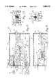
- FIG. 1is a diagrammatic side elevational view of a catheter constructed according to one embodiment of the present invention, with the break lines indicating continuous length and the catheter shown inserted with its tip end in position to effect treatment of an arterial plaque deposit;
- FIG. 2is a diagrammatic side elevational view of a catheter which is similar to that shown in FIG. 1 but which includes a plurality of different optical fibers each of which transmits both ultrasound and laser energy;
- FIG. 3is a fragmentary end elevational view taken generally along line 3--3 of FIG. 2 in the direction of the arrows;
- FIG. 4is a fragmentary perspective view of a catheter constructed according to a modified embodiment of the invention.
- FIG. 5is a fragmentary perspective view of a catheter constructed according to still another modified embodiment of the invention.
- FIG. 6is a fragmentary diagrammatic view of a catheter constructed according to yet another modified embodiment of the invention.
- FIG. 7is a fragmentary diagrammatic view of a catheter constructed according to still another embodiment of the invention.
- FIG. 8is a fragmentary diagrammatic view of a catheter constructed according to yet another embodiment of the invention, with the solid line showing the input end of the catheter positioned adjacent a window to receive laser energy and the broken lines showing the input end of the catheter positioned adjacent to a port for receiving ultrasound;
- FIG. 9is a fragmentary diagrammatic view similar to FIG. 8, but showing the input end of the catheter positioned about midway between the port and the window and being wiped by a wiper;
- FIG. 10is a fragmentary sectional view on an enlarged scale taken generally along line 10--10 of FIG. 8 in the direction of the arrows;
- FIG. 11is a fragmentary sectional view taken generally along line 11--11 of FIG. 8 in the direction of the arrows.
- FIG. 1a catheter which is constructed according to one embodiment of the present invention is generally identified by numeral 10.
- the catheter 10includes an elongated flexible catheter tube 12 which is hollow and preferably circular in crosssection.
- the catheter tube 12is constructed in a suitable manner to be inserted into the body with one end 14 situated adjacent to the area that is to be treated and the other end 16 remaining external of the body.
- FIG. 1depicts use of the catheter 10 in the treatment of atherosclerotic plaque 18 which has built up on the wall of an artery 20.
- the distal end 14 of the catheter tube 12is inserted into the artery 20 to the location of the plaque deposit 18.
- An annular seal 22may be provided near the distal end 14 to effect a seal between the outside of the catheter tube 12 and the arterial wall.
- An optical fiber 24extends through the catheter tube 12 and terminates in a tip 26 which may project out through the distal end 14 of the catheter tube.
- the opposite or input end of the optical fiber 24suitably connects with a Y-shaped fiber coupler having two branches 28 and 30 that merge at a junction 32.
- the fiber coupleris a commercially available article, and it may be fused or otherwise suitably connected end to end with the main optical fiber 24.
- the fiber 24 and the fiber couplermay be quartz or silicon fiber coated with an external reflective material.
- a conventional ultrasonic transducer 34is located outside of the catheter tube 12 and is excited electrically in the usual manner to transmit ultrasonic signals through a piezo-electrode.
- the transducer 34connects with the free end of branch 28 through a tapered transition element 38.
- the ultrasonic signals which are transmitted to the transition element 38 by the transducerare transmitted along the branch 28 to the fiber 24 and are directed to the area that is to undergo treatment through the fiber tip 26.
- Pulse echoeswhich are reflections of the transmitted signals are received by the tip 26 and are transmitted along the fiber 24 and the branch 28 back to the transducer.
- the transducertransforms the received pulse echoes into electrical signals which provide data to form an image of the area that is to undergo treatment.
- the ultrasonic systemprovides images as to the configuration, location and character of the tissue in the area of the plaque 18.
- the transduceris a piezo-electric ceramic crystal unit.
- the tapered transition element 38may be a solid frusto-conical member constructed of a substance suitable to conduct ultrasonic signals.
- the transition element 38may take the form of a hollow frusto-conical member that is filled with a fluid capable of conducting ultrasonic signals.
- the large end of the transition element 38connects with the piezo-electrode 36, and the small end connects with the free end of the branch 28.
- Laser energyis applied to the free end of the other branch 30 by a medical laser 40.
- the laser energyis applied to the branch 30 and is transmitted along the branch and the fiber 24 to the tip 26 which directs the laser energy toward the plaque 18 in order to remove the plaque 18 or at least reduce the plaque build up.
- FIGS. 2 and 3depict an alternative embodiment of the invention in which the catheter tube 12 contains a plurality of the optical fibers 24.
- Each of the fibers 24is fused or otherwise connected at its proximal end with a fiber coupler having a pair of branches 28 and 30.
- the branches 28connect with respective transducers 34 via transition elements 38. Consequently, each of the fibers 24 receives ultrasonic signals from the corresponding transducer 34 and transmits reflected pulse echoes back to the corresponding transducer 34.
- the plural transducers 34provide accurate ultrasonic imaging information of the area that is to undergo treatment.
- the fibers 24may be arranged in a circular pattern, and the branches 30 may be arranged in line with the respective fibers 24 such that the branches 30 are essentially in line extensions of the fibers.
- the extensions 30are thus arranged in a circular pattern, as best shown in FIG. 3.
- the laser 40may be used to apply laser energy to the free ends of the extensions 30, and the extensions and fibers 24 transmit the laser energy through the catheter tube 12 to the area undergoing treatment. Because of the circular arrangement of the fibers 24, the transducers 34 may be arranged in a circular pattern, as shown in FIG. 3.
- FIG. 4depicts another modified embodiment of the invention in which the transition element 38 is fused or otherwise connected directly to the proximal end of the fiber 24.
- the transducer 34applies ultrasonic signals to the fiber 24 through the transition element 38 in the manner previously described, and the pulse echoes are transmitted back to the transducer in the same fashion described previously as well.
- the laser 40applies laser energy to a small optical fiber or filament 42.
- the filament 42may take the form of an optical fiber having a construction similar to that of the fiber 24 but a diameter considerably less than that of the fiber 24.
- the filament 42extends through a passage 44 which is formed through the transducer 34 and transition element 38. The end of the filament 42 butts against the input end of the fiber 24 and is fused or otherwise suitably connected with the optical fiber.
- the laser energy which is applied to the filament 42is thus applied to the input end of the optical fiber 24 and is transmitted along the optical fiber and applied to treat the medical problem that is undergoing treatment.
- FIG. 5depicts an alternative embodiment of the invention in which the transition element 38 connects with one end of an optical fiber or filament 46.
- the piezo-electrode of the transducer 34is connected to the transition element 38 as previously described.
- the opposite end of the filament 46extends to and connects with the proximal end of the optical fiber 24.
- the filament 46may be constructed in a manner similar to the fiber 24, but filament 46 is considerably smaller in diameter than the fiber 24.
- the end of the fiber 46is fused or otherwise suitably connected with the end of the fiber 24.
- the transducer 34applies ultrasonic signals to filament 46 which in turn applies the signals to the fiber 24.
- the pulse echoesare transmitted back to the transducer to provide ultrasonic imaging data of the area that is to undergo treatment.
- a plurality of additional filaments 50connect with the proximal end of fiber 24 (as by fusing, for example) and may be arranged in a circular pattern around the filament 46.
- the filaments 50may be larger or smaller than the central filament 46, and they may be constructed in a manner similar to the fiber 24. However, the filaments 50 are preferably somewhat smaller in diameter than the central filament 46.
- the laser 40operates to apply laser energy to the filaments 50, and the laser energy is transmitted along the filaments 50 to the fiber 24 which transmits the laser energy along it and applies the laser energy to the area that is undergoing treatment.
- FIG. 6depicts yet another alternative embodiment of the invention in which the transition element 38 is connected with the proximal end of the fiber 24.
- the transducer 34operates in the same manner described previously to provide ultrasonic imaging data of the area that is to undergo treatment.
- the exterior of the fiber 24is provided with an optical coating.
- a small area 52 on the surface of the fiber 24is devoid of the optical coating, thus providing a small "window" through which laser energy is able to enter the fiber 24 and thereafter propagate along the length of the optical fiber for application to the area undergoing treatment.
- the laser 40applies laser energy through a beam splitter 54 which directs the laser energy in a beam 56 toward the window area 52 on the surface of the fiber 24. In this manner, the laser energy is applied to the fiber 24 and is transmitted along the fiber to treat the afflicted area. If necessary, measures can be taken to assure that the laser energy propogates away from the transducer.
- FIG. 7depicts an embodiment of the invention which is similar to that depicted in FIG. 6, the difference being that in the FIG. 7 embodiment a plurality of the fibers 24 extend through the catheter tube 12, with each fiber 24 equipped with a transducer 34.
- the laser 40applies laser energy to the beam splitter 54, and the beam splitter splits the laser energy into separate beams 56 which are applied to the window areas 52 of the respective fibers 24. Consequently, laser energy is applied to each of the fibers 24 and is transmitted along the fibers and applied to the afflicted area at the distal end of the catheter tube.
- the beam splittercan operate to direct the beams 56 to only those fibers that require laser energy for treatment of the condition that is indicated by the ultrasonic information.
- FIGS. 8-11depict yet another embodiment of the invention in which the part of the catheter tube near the proximal end 16 extends within a tank 58.
- the tank 58has a flat bottom 60 opposite end panels 62 and 64 and opposite side walls 66 and 68 (see FIG. 10).
- a removable cover 70fits on top of the tank 58.
- the catheter 12extends through the end panel 64 and is sealed to panel 64 by a seal element 72.
- the end panel 62is provided with a window 74 located near its top end and with a port 76 located near its bottom end below the level of the window 74.
- the laser 40can be operated to apply laser energy to the window 74 and through the window to a plurality of optical fibers 24 contained in the catheter tube 12.
- the port 76is located below the level of a liquid 78 which is contained within the tank 58.
- the liquid 78may be glycerin, water or another liquid that is able to transmit ultrasound.
- Connected with the port 76are a plurality of transducers 34, each of which has an optical fiber 80 extending from it to the port 76.
- the catheter tube 12When the catheter tube 12 is connected with the port 76, ultrasound signals are transmitted from the transducers 34 along the fibers 80 to the port 76 and from the port to the optical fibers 24 which extend within the catheter tube 12. Return pulse echoes are transmitted along the fibers 24 to the port 76 and from the port to the transducers 34 along fibers 80.
- the fibers 80may be surrounded by a suitable sealant which seals them to port 76 to make the port liquid tight.
- the proximal end of the catheter tube 12is transferred between the window 74 and the port 76 by a mechanism which includes a carriage in the form of a collar 82 which is sleeved on a spool 84 fixed to the proximal end 16 of the catheter tube 12.
- the collar 82fits slidably on the spool 84.
- One end of the spool 84is provided with a flange 86 which limits movement of the collar on the spool in one direction.
- the opposite end of the spool 84is provided with an end plate 88 having a pair of alignment openings 90 (see FIG. 11) located on opposite sides of the catheter tube 12.
- a pair of alignment pins 92project inwardly from panel 62 on opposite sides of the window 74 and are positioned to receive the openings 90 in order to properly align the catheter tube with the window 74.
- Another pair of alignment pins 94project from panel 62 on opposite sides of the port 76. When the catheter tube 12 is applied to the port 76, the alignment pins 94 receive the alignment openings 90 in order to assure that the catheter tube 12 is properly aligned with the port 76.
- a compression spring 96is coiled around the spool 84 and acts against plate 88 at one end and against the collar 82 at the other end, thereby urging the end plate 80 and collar 82 apart.
- the collar 82travels along a prescribed path defined by a pair of curved tracks 98 which are formed in the side walls 66 and 68 of tank 58. As shown in FIG. 10, the collar 82 is equipped with a pair of shafts 100 which project from the collar on opposite sides. Carried on the outer ends of the shafts 100 are guide elements 102 which fit closely in the tracks 98. By reason of the guide elements 102 traveling along the tracks 98, the collar 82 is guided along the path defined by the tracks 98 in order to guide the catheter end between one position in which it is aligned with window 74 and another position in which it is aligned with port 76.
- Movement of the collar 82is effected by a conventional electric motor 104 (FIG. 8) which drives an output shaft 106.
- a conventional electric motor 104(FIG. 8) which drives an output shaft 106.
- Carried on the shaft 106is an eccentric or a cam 108.
- One end of a rigid link 110is pinned at 112 to the cam 108 at a location offset from the shaft 106.
- the opposite end of the link 110is pivoted to one of the shafts 100 and retained on the shaft by a retaining element 113.
- an arm 114Extending inwardly from panel 62 at a location between the window 74 and port 76 is an arm 114. Carried on the free end of the arm 114 is a suitable wiping element 116 which may take the form of a wiping blade tapering down to a wiping edge 118. The location of the wiping element 116 is such that it is contacted by the end of the catheter tube 12 and the ends of the fibers 24 as the catheter tube is moved between its two different positions. When the catheter tube is moved from the port 76 toward the window 74, the ends of the fibers 24 are wiped of the liquid 78. Preferably, the wiping element 116 is located a short distance above the level of the liquid 78.
- FIGS. 8-12operates to provide ultrasonic imaging of the area that is to undergo treatment and to effect the treatment via laser energy applied by the laser 40.
- the catheter tube 12When the catheter tube 12 is positioned against the port 76, ultrasonic signals are applied to the fibers 24 through the window, and pulse echoes are applied back from the fibers 24 through the window 76 to the ultrasonic transducers 34. In this manner, ultrasonic images of the area that is to undergo treatment are obtained.
- the catheter tube 12When the laser treatment is to be carried out, the catheter tube 12 is moved from the lower position in which it is aligned with the port 76 to the upper position in which it is aligned with the window 74. Movement of the catheter tube is carried out by operating the motor 104 in a direction causing the cam 108 to rotate one revolution in a counterclockwise direction. As the cam rotates, the link 110 pulls on collar 82, and the collar acts against flange 86 to pull the spool 84 in a direction away from the port 76. The guide elements 102 follow the tracks 98. When the cam has rotated through half a revolution, the collar 82 is located approximately midway along the track 98.
- the end of the catheter tube 12 and the fibers 24are wiped clear of the liquid 78 as the end of the catheter emerges from the liquid.
- the end of the catheteris swept across the wiping element 118 which acts to remove any liquid that may be present on the fibers. Consequently, the fibers are clear of liquid when the catheter tube is positioned against the window 74.
- the cam 108In order to move the catheter tube again to the lower position, the cam 108 is rotated one revolution in a clockwise direction.
- the guiding action provided by the guide elements 108 and tracks 98carries the catheter tube from the window 74 to the port 76.
- the alignment pins 94receive the alignment openings 90 to assure that the end of the catheter tube is precisely aligned with the port 76.
- the spring 96is compressed, and this presses the end plate 88 against panel 62 to assure that the end of the catheter tube is held against the port 76.
Landscapes
- Health & Medical Sciences (AREA)
- Surgery (AREA)
- Physics & Mathematics (AREA)
- Life Sciences & Earth Sciences (AREA)
- Biomedical Technology (AREA)
- Heart & Thoracic Surgery (AREA)
- Otolaryngology (AREA)
- Electromagnetism (AREA)
- Optics & Photonics (AREA)
- Engineering & Computer Science (AREA)
- Vascular Medicine (AREA)
- Nuclear Medicine, Radiotherapy & Molecular Imaging (AREA)
- Medical Informatics (AREA)
- Molecular Biology (AREA)
- Animal Behavior & Ethology (AREA)
- General Health & Medical Sciences (AREA)
- Public Health (AREA)
- Veterinary Medicine (AREA)
- Laser Surgery Devices (AREA)
- Radiation-Therapy Devices (AREA)
Abstract
Description
Claims (7)
Priority Applications (2)
| Application Number | Priority Date | Filing Date | Title |
|---|---|---|---|
| PCT/US1994/001987WO1995022283A1 (en) | 1992-10-26 | 1994-02-22 | Catheter using optical fibers to transmit laser and ultrasonic energy |
| US08/310,498US5486170A (en) | 1992-10-26 | 1994-09-22 | Medical catheter using optical fibers that transmit both laser energy and ultrasonic imaging signals |
Applications Claiming Priority (3)
| Application Number | Priority Date | Filing Date | Title |
|---|---|---|---|
| US07/966,279US5350377A (en) | 1992-10-26 | 1992-10-26 | Medical catheter using optical fibers that transmit both laser energy and ultrasonic imaging signals |
| PCT/US1994/001987WO1995022283A1 (en) | 1992-10-26 | 1994-02-22 | Catheter using optical fibers to transmit laser and ultrasonic energy |
| US08/310,498US5486170A (en) | 1992-10-26 | 1994-09-22 | Medical catheter using optical fibers that transmit both laser energy and ultrasonic imaging signals |
Related Parent Applications (1)
| Application Number | Title | Priority Date | Filing Date |
|---|---|---|---|
| US07/966,279DivisionUS5350377A (en) | 1992-10-26 | 1992-10-26 | Medical catheter using optical fibers that transmit both laser energy and ultrasonic imaging signals |
Publications (1)
| Publication Number | Publication Date |
|---|---|
| US5486170Atrue US5486170A (en) | 1996-01-23 |
Family
ID=27377619
Family Applications (1)
| Application Number | Title | Priority Date | Filing Date |
|---|---|---|---|
| US08/310,498Expired - LifetimeUS5486170A (en) | 1992-10-26 | 1994-09-22 | Medical catheter using optical fibers that transmit both laser energy and ultrasonic imaging signals |
Country Status (2)
| Country | Link |
|---|---|
| US (1) | US5486170A (en) |
| WO (1) | WO1995022283A1 (en) |
Cited By (87)
| Publication number | Priority date | Publication date | Assignee | Title |
|---|---|---|---|---|
| US5836905A (en)* | 1994-06-20 | 1998-11-17 | Lemelson; Jerome H. | Apparatus and methods for gene therapy |
| US5944687A (en)* | 1996-04-24 | 1999-08-31 | The Regents Of The University Of California | Opto-acoustic transducer for medical applications |
| US5968064A (en)* | 1997-02-28 | 1999-10-19 | Lumend, Inc. | Catheter system for treating a vascular occlusion |
| US6010449A (en)* | 1997-02-28 | 2000-01-04 | Lumend, Inc. | Intravascular catheter system for treating a vascular occlusion |
| US6022309A (en)* | 1996-04-24 | 2000-02-08 | The Regents Of The University Of California | Opto-acoustic thrombolysis |
| US6081738A (en)* | 1998-01-15 | 2000-06-27 | Lumend, Inc. | Method and apparatus for the guided bypass of coronary occlusions |
| US6120516A (en)* | 1997-02-28 | 2000-09-19 | Lumend, Inc. | Method for treating vascular occlusion |
| US6217549B1 (en) | 1997-02-28 | 2001-04-17 | Lumend, Inc. | Methods and apparatus for treating vascular occlusions |
| US6217527B1 (en) | 1998-09-30 | 2001-04-17 | Lumend, Inc. | Methods and apparatus for crossing vascular occlusions |
| US6231546B1 (en) | 1998-01-13 | 2001-05-15 | Lumend, Inc. | Methods and apparatus for crossing total occlusions in blood vessels |
| WO2001049196A1 (en)* | 1999-12-31 | 2001-07-12 | Oratec Interventions, Inc. | Thermal protection for methods of treating arthroscopic pathologies |
| US6266550B1 (en) | 1998-01-16 | 2001-07-24 | Lumend, Inc. | Catheter apparatus for treating arterial occlusions |
| US20020045890A1 (en)* | 1996-04-24 | 2002-04-18 | The Regents Of The University O F California | Opto-acoustic thrombolysis |
| US20020058961A1 (en)* | 2000-10-16 | 2002-05-16 | Aguilar Amiel R. | Catheter |
| US6390978B1 (en)* | 1999-10-01 | 2002-05-21 | Karl Storz Gmbh & Co. Kg | Imaging method for determining a physical or chemical condition of tissue in human or animal bodies, and system for carrying out the method |
| US6395016B1 (en) | 1996-07-28 | 2002-05-28 | Biosense, Inc. | Method of treating a heart using cells irradiated in vitro with biostimulatory irradiation |
| US6398798B2 (en) | 1998-02-28 | 2002-06-04 | Lumend, Inc. | Catheter system for treating a vascular occlusion |
| US20020103459A1 (en)* | 2000-12-05 | 2002-08-01 | Sparks Kurt D. | Catheter system for vascular re-entry from a sub-intimal space |
| US20020143358A1 (en)* | 2001-02-13 | 2002-10-03 | Domingo Nicanor A. | Method and apparatus for micro-dissection of vascular occlusions |
| US6471692B1 (en)* | 1998-06-24 | 2002-10-29 | Laser Industries Ltd. | System and method for manipulating movement of an energy emitting device within a body cavity |
| US6508825B1 (en) | 1997-02-28 | 2003-01-21 | Lumend, Inc. | Apparatus for treating vascular occlusions |
| US20030073904A1 (en)* | 2001-10-15 | 2003-04-17 | Hondaseiki Corporation | Ultrasonic medical treatment equipment and ultrasonic diagnostic equipment |
| US6695839B2 (en) | 2001-02-08 | 2004-02-24 | Oratec Interventions, Inc. | Method and apparatus for treatment of disrupted articular cartilage |
| US6699242B2 (en) | 2000-02-03 | 2004-03-02 | Baylor College Of Medicine | Methods and devices for intraosseous nerve ablation |
| US20040067000A1 (en)* | 2002-10-07 | 2004-04-08 | Bates Kenneth N. | Systems and methods for minimally-invasive optical-acoustic imaging |
| US20040230258A1 (en)* | 2003-02-19 | 2004-11-18 | Palomar Medical Technologies, Inc. | Method and apparatus for treating pseudofolliculitis barbae |
| US20050021013A1 (en)* | 1997-10-21 | 2005-01-27 | Endo Vasix, Inc. | Photoacoustic removal of occlusions from blood vessels |
| US20050021002A1 (en)* | 2003-06-10 | 2005-01-27 | Deckman Robert K. | Catheter systems and methods for crossing vascular occlusions |
| US20050171478A1 (en)* | 1998-01-13 | 2005-08-04 | Selmon Matthew R. | Catheter system for crossing total occlusions in vasculature |
| US20060004347A1 (en)* | 2000-12-28 | 2006-01-05 | Palomar Medical Technologies, Inc. | Methods and products for producing lattices of EMR-treated islets in tissues, and uses therefor |
| US20060194164A1 (en)* | 2004-12-09 | 2006-08-31 | Palomar Medical Technologies, Inc. | Oral appliance with heat transfer mechanism |
| US20070027440A1 (en)* | 2001-03-02 | 2007-02-01 | Palomar Medical Technologies, Inc. | Apparatus and method for photocosmetic and photodermatological treatment |
| US20070032808A1 (en)* | 2005-08-03 | 2007-02-08 | Azam Anwar | System and method for addressing total occlusion in a vascular environment |
| US20070049910A1 (en)* | 2005-08-08 | 2007-03-01 | Palomar Medical Technologies, Inc. | Eye-safe photocosmetic device |
| US20070078501A1 (en)* | 2002-05-23 | 2007-04-05 | Palomar Medical Technologies, Inc. | Phototreatment device for use with coolants and topical substances |
| US20070116408A1 (en)* | 2005-11-22 | 2007-05-24 | Eberle Michael J | Optical imaging probe connector |
| US20070213792A1 (en)* | 2002-10-07 | 2007-09-13 | Palomar Medical Technologies, Inc. | Treatment Of Tissue Volume With Radiant Energy |
| WO2007084981A3 (en)* | 2006-01-19 | 2007-11-29 | Univ Michigan | System and method for photoacoustic imaging and monitoring of laser therapy |
| US20080033516A1 (en)* | 2002-10-07 | 2008-02-07 | Palomar Medical Technologies, Inc. | Methods and apparatus for performing photobiostimulation |
| US20080058789A1 (en)* | 2006-09-06 | 2008-03-06 | Cardiofirst | Guidance system used in treating chronic occlusion |
| US20080103565A1 (en)* | 2002-06-19 | 2008-05-01 | Palomar Medical Technologies, Inc. | Method and apparatus for treatment of cutaneous and subcutaneous conditions |
| US20080123083A1 (en)* | 2006-11-29 | 2008-05-29 | The Regents Of The University Of Michigan | System and Method for Photoacoustic Guided Diffuse Optical Imaging |
| US20080132886A1 (en)* | 2004-04-09 | 2008-06-05 | Palomar Medical Technologies, Inc. | Use of fractional emr technology on incisions and internal tissues |
| US20080154157A1 (en)* | 2006-12-13 | 2008-06-26 | Palomar Medical Technologies, Inc. | Cosmetic and biomedical applications of ultrasonic energy and methods of generation thereof |
| US20080172047A1 (en)* | 2000-12-28 | 2008-07-17 | Palomar Medical Technologies, Inc. | Methods And Devices For Fractional Ablation Of Tissue |
| US20080173093A1 (en)* | 2007-01-18 | 2008-07-24 | The Regents Of The University Of Michigan | System and method for photoacoustic tomography of joints |
| US20080221647A1 (en)* | 2007-02-23 | 2008-09-11 | The Regents Of The University Of Michigan | System and method for monitoring photodynamic therapy |
| US20090012511A1 (en)* | 2007-06-08 | 2009-01-08 | Cynosure, Inc. | Surgical waveguide |
| US20090054763A1 (en)* | 2006-01-19 | 2009-02-26 | The Regents Of The University Of Michigan | System and method for spectroscopic photoacoustic tomography |
| US7527594B2 (en) | 1998-03-05 | 2009-05-05 | Vascular Imaging Corporation | Optical-acoustic imaging device |
| US20090292277A1 (en)* | 2006-08-02 | 2009-11-26 | Cynosure, Inc. | Picosecond laser apparatus and methods for its operation and use |
| US20100087732A1 (en)* | 2008-10-02 | 2010-04-08 | Vascular Imaging Corporation | Optical ultrasound receiver |
| US7758621B2 (en) | 1997-05-15 | 2010-07-20 | Palomar Medical Technologies, Inc. | Method and apparatus for therapeutic EMR treatment on the skin |
| US7763016B2 (en) | 1997-05-15 | 2010-07-27 | Palomar Medical Technologies, Inc. | Light energy delivery head |
| US20100249891A1 (en)* | 2009-03-26 | 2010-09-30 | Arista Therapeutics, Inc. | Implantable apparatus for the treatment of a surface of a damaged vessel or body cavity by electromagnetic energy |
| US20100324506A1 (en)* | 2008-09-26 | 2010-12-23 | Relievant Medsystems, Inc. | Systems and methods for navigating an instrument through bone |
| US20110190747A1 (en)* | 2010-01-29 | 2011-08-04 | Arista Therapeutics, Inc. | Disposable led/laser catheter |
| US20110190748A1 (en)* | 2010-01-29 | 2011-08-04 | Arista Therapeutics, Inc. | Laparoscope for low laser level irradiation |
| US8182473B2 (en) | 1999-01-08 | 2012-05-22 | Palomar Medical Technologies | Cooling system for a photocosmetic device |
| US8328794B2 (en) | 1996-12-02 | 2012-12-11 | Palomar Medical Technologies, Inc. | System for electromagnetic radiation dermatology and head for use therewith |
| US8346347B2 (en) | 2005-09-15 | 2013-01-01 | Palomar Medical Technologies, Inc. | Skin optical characterization device |
| US8361067B2 (en) | 2002-09-30 | 2013-01-29 | Relievant Medsystems, Inc. | Methods of therapeutically heating a vertebral body to treat back pain |
| US8419730B2 (en) | 2008-09-26 | 2013-04-16 | Relievant Medsystems, Inc. | Systems and methods for navigating an instrument through bone |
| US8425507B2 (en) | 2002-09-30 | 2013-04-23 | Relievant Medsystems, Inc. | Basivertebral nerve denervation |
| US8882764B2 (en) | 2003-03-28 | 2014-11-11 | Relievant Medsystems, Inc. | Thermal denervation devices |
| USRE46356E1 (en) | 2002-09-30 | 2017-04-04 | Relievant Medsystems, Inc. | Method of treating an intraosseous nerve |
| US9724151B2 (en) | 2013-08-08 | 2017-08-08 | Relievant Medsystems, Inc. | Modulating nerves within bone using bone fasteners |
| US9724107B2 (en) | 2008-09-26 | 2017-08-08 | Relievant Medsystems, Inc. | Nerve modulation systems |
| US9775627B2 (en) | 2012-11-05 | 2017-10-03 | Relievant Medsystems, Inc. | Systems and methods for creating curved paths through bone and modulating nerves within the bone |
| US9780518B2 (en) | 2012-04-18 | 2017-10-03 | Cynosure, Inc. | Picosecond laser apparatus and methods for treating target tissues with same |
| US9919168B2 (en) | 2009-07-23 | 2018-03-20 | Palomar Medical Technologies, Inc. | Method for improvement of cellulite appearance |
| WO2019034544A1 (en)* | 2017-08-15 | 2019-02-21 | Koninklijke Philips N.V. | Intraluminal ultrasound device for diagnostic imaging and therapy |
| US10245107B2 (en) | 2013-03-15 | 2019-04-02 | Cynosure, Inc. | Picosecond optical radiation systems and methods of use |
| US10390877B2 (en) | 2011-12-30 | 2019-08-27 | Relievant Medsystems, Inc. | Systems and methods for treating back pain |
| US10434324B2 (en) | 2005-04-22 | 2019-10-08 | Cynosure, Llc | Methods and systems for laser treatment using non-uniform output beam |
| US10588691B2 (en) | 2012-09-12 | 2020-03-17 | Relievant Medsystems, Inc. | Radiofrequency ablation of tissue within a vertebral body |
| US10772683B2 (en) | 2014-05-18 | 2020-09-15 | Eximo Medical Ltd. | System for tissue ablation using pulsed laser |
| US11007010B2 (en) | 2019-09-12 | 2021-05-18 | Relevant Medsysterns, Inc. | Curved bone access systems |
| US11272831B2 (en)* | 2016-08-24 | 2022-03-15 | Unist(Ulsan National Institute Of Science And Technology) | Photoacoustic and ultrasonic endoscopy system including a coaxially configured optical and electromagnetic rotary waveguide assembly and implementation method thereof |
| US11418000B2 (en) | 2018-02-26 | 2022-08-16 | Cynosure, Llc | Q-switched cavity dumped sub-nanosecond laser |
| US11576724B2 (en) | 2011-02-24 | 2023-02-14 | Eximo Medical Ltd. | Hybrid catheter for vascular intervention |
| US11684420B2 (en) | 2016-05-05 | 2023-06-27 | Eximo Medical Ltd. | Apparatus and methods for resecting and/or ablating an undesired tissue |
| US12039731B2 (en) | 2020-12-22 | 2024-07-16 | Relievant Medsystems, Inc. | Prediction of candidates for spinal neuromodulation |
| US12038322B2 (en) | 2022-06-21 | 2024-07-16 | Eximo Medical Ltd. | Devices and methods for testing ablation systems |
| US12082876B1 (en) | 2020-09-28 | 2024-09-10 | Relievant Medsystems, Inc. | Introducer drill |
| US12376904B1 (en) | 2020-09-08 | 2025-08-05 | Angiodynamics, Inc. | Dynamic laser stabilization and calibration system |
| US12433668B1 (en) | 2021-11-08 | 2025-10-07 | Relievant Medsystems, Inc. | Impedance stoppage mitigation during radiofrequency tissue ablation procedures |
Families Citing this family (1)
| Publication number | Priority date | Publication date | Assignee | Title |
|---|---|---|---|---|
| US5989208A (en)* | 1997-05-16 | 1999-11-23 | Nita; Henry | Therapeutic ultrasound system |
Citations (44)
| Publication number | Priority date | Publication date | Assignee | Title |
|---|---|---|---|---|
| US3264863A (en)* | 1963-05-27 | 1966-08-09 | Maropis Nicholas | Method and apparatus for detecting incipient boiling of a liquid |
| US3470868A (en)* | 1964-06-06 | 1969-10-07 | Siemens Ag | Ultrasound diagnostic apparatus |
| SU376712A1 (en)* | 1968-08-29 | 1973-04-05 | LIBRARY | |
| US3779234A (en)* | 1971-06-30 | 1973-12-18 | Intersc Res Inst | Ultrasonic catheter with rotating transducers |
| US3915018A (en)* | 1974-11-21 | 1975-10-28 | Us Energy | Transition section for acoustic waveguides |
| US3938502A (en)* | 1972-02-22 | 1976-02-17 | Nicolaas Bom | Apparatus with a catheter for examining hollow organs or bodies with the ultrasonic waves |
| US4008455A (en)* | 1975-02-24 | 1977-02-15 | Westinghouse Electric Corporation | Method of making self-calibrated displacement measurements |
| US4208917A (en)* | 1978-02-27 | 1980-06-24 | Kabushiki Kaisha Toyota Chuo Kenkyusho | Device for inspecting spot welds |
| US4232385A (en)* | 1977-07-12 | 1980-11-04 | Her Majesty The Queen In Right Of Canada, As Represented By The Minister Of National Defence | Frequency division multiplexing system for optical transmission of broadband signals |
| US4284473A (en)* | 1978-03-27 | 1981-08-18 | Tokyo Shibaura Denki Kabushiki Kaisha | Submerged ultrasonic viewer for a nuclear reactor |
| US4337661A (en)* | 1979-01-23 | 1982-07-06 | Kretztechnik Gesellschaft M.B.H. | Equipment for ultrasonic examination |
| US4349032A (en)* | 1978-12-15 | 1982-09-14 | Olympus Optical Co., Ltd. | Endoscope with an ultrasonic probe |
| US4462408A (en)* | 1982-05-17 | 1984-07-31 | Advanced Technology Laboratories, Inc. | Ultrasonic endoscope having elongated array mounted in manner allowing it to remain flexible |
| US4466443A (en)* | 1981-04-08 | 1984-08-21 | Olympus Optical Co., Ltd. | Ultrasonic diagnostic apparatus for examination of a coeliac cavity |
| US4576177A (en)* | 1983-02-18 | 1986-03-18 | Webster Wilton W Jr | Catheter for removing arteriosclerotic plaque |
| US4587972A (en)* | 1984-07-16 | 1986-05-13 | Morantte Jr Bernardo D | Device for diagnostic and therapeutic intravascular intervention |
| US4605009A (en)* | 1983-04-06 | 1986-08-12 | Universite Francois Rabelais | Ultrasonic sweep echography and display endoscopic probe |
| WO1987001269A1 (en)* | 1985-09-02 | 1987-03-12 | Medical Innovation Company A/S | Method for ultrasound examination and ultrasonic conductor for carrying out the method |
| JPS62127665A (en)* | 1985-11-29 | 1987-06-09 | Anritsu Corp | Guiding device for ultrasonic wave and light in one end of optical fiber |
| US4686979A (en)* | 1984-01-09 | 1987-08-18 | The United States Of America As Represented By The United States Department Of Energy | Excimer laser phototherapy for the dissolution of abnormal growth |
| JPS62270140A (en)* | 1986-02-28 | 1987-11-24 | カ−デイオヴアスキユラ− イメイジングシステムズ インコ−ポレ−テツド | Catheter apparatus and method for two-dimensional ultrasonicexamination in blood vessel |
| US4757818A (en)* | 1986-03-03 | 1988-07-19 | Angelsen Bjorn A J | Ultrasonic transducer probe with linear motion drive mechanism |
| US4764334A (en)* | 1983-10-17 | 1988-08-16 | Westinghouse Electric Corp. | Visual inspection system for radioactive fuel assemblies using fiberoptics |
| EP0325836A2 (en)* | 1988-01-21 | 1989-08-02 | C.R. Bard, Inc. | Laser tipped catheter |
| EP0329492A2 (en)* | 1988-02-18 | 1989-08-23 | Bjorn A. J. Angelsen | Laser catheter delivery system |
| US4869258A (en)* | 1986-12-05 | 1989-09-26 | Siemens Aktiengesellschaft | Intracavitary ultrasound scanner means |
| US4930515A (en)* | 1988-10-04 | 1990-06-05 | Diasonics, Inc. | Ultrasound probe with multi-orientation tip-mounted transducer |
| US4950267A (en)* | 1987-11-27 | 1990-08-21 | Olympus Optical Co., Ltd. | Laser beam treatment device for an endoscope |
| US4951677A (en)* | 1988-03-21 | 1990-08-28 | Prutech Research And Development Partnership Ii | Acoustic imaging catheter and the like |
| US4957112A (en)* | 1987-11-20 | 1990-09-18 | Olympus Optical Co., Ltd. | Ultrasonic diagnostic apparatus |
| US4972839A (en)* | 1988-12-22 | 1990-11-27 | Angelsen Bjorn A J | Miniaturized mechanically-steerable ultrasonic probe |
| US5010886A (en)* | 1989-08-18 | 1991-04-30 | Intertherapy, Inc. | Medical probe assembly having combined ultrasonic imaging and laser ablation capabilities |
| US5022399A (en)* | 1989-05-10 | 1991-06-11 | Biegeleisen Ken P | Venoscope |
| US5024092A (en)* | 1990-08-16 | 1991-06-18 | Westinghouse Electric Corp. | Method and apparatus for selective transmission and reflection of sound through a solid |
| US5029588A (en)* | 1989-06-15 | 1991-07-09 | Cardiovascular Imaging Systems, Inc. | Laser catheter with imaging capability |
| US5054492A (en)* | 1990-12-17 | 1991-10-08 | Cardiovascular Imaging Systems, Inc. | Ultrasonic imaging catheter having rotational image correlation |
| US5152291A (en)* | 1990-09-07 | 1992-10-06 | Hewlett-Packard Company | Acoustic fiber measurement of intravascular blood |
| US5163432A (en)* | 1990-07-16 | 1992-11-17 | Matsushita Electric Industrial Co., Ltd. | Catheter type laser illuminating apparatus |
| US5170793A (en)* | 1990-02-07 | 1992-12-15 | Kabushiki Kaisha Toshiba | Ultrasonic probe |
| US5195519A (en)* | 1988-12-22 | 1993-03-23 | Angelsen Bjorn A J | Miniaturized mechanically-steerable ultrasonic probe |
| US5217018A (en)* | 1989-05-16 | 1993-06-08 | Hewlett-Packard Company | Acoustic transmission through cladded core waveguide |
| US5254112A (en)* | 1990-10-29 | 1993-10-19 | C. R. Bard, Inc. | Device for use in laser angioplasty |
| US5257628A (en)* | 1991-07-11 | 1993-11-02 | Fuji Photo Optical Co., Ltd. | Ultrasound internal examination system |
| US5284148A (en)* | 1989-05-16 | 1994-02-08 | Hewlett-Packard Company | Intracavity ultrasound diagnostic probe using fiber acoustic waveguides |
- 1994
- 1994-02-22WOPCT/US1994/001987patent/WO1995022283A1/enactiveIP Right Grant
- 1994-09-22USUS08/310,498patent/US5486170A/ennot_activeExpired - Lifetime
Patent Citations (46)
| Publication number | Priority date | Publication date | Assignee | Title |
|---|---|---|---|---|
| US3264863A (en)* | 1963-05-27 | 1966-08-09 | Maropis Nicholas | Method and apparatus for detecting incipient boiling of a liquid |
| US3470868A (en)* | 1964-06-06 | 1969-10-07 | Siemens Ag | Ultrasound diagnostic apparatus |
| SU376712A1 (en)* | 1968-08-29 | 1973-04-05 | LIBRARY | |
| US3779234A (en)* | 1971-06-30 | 1973-12-18 | Intersc Res Inst | Ultrasonic catheter with rotating transducers |
| US3938502A (en)* | 1972-02-22 | 1976-02-17 | Nicolaas Bom | Apparatus with a catheter for examining hollow organs or bodies with the ultrasonic waves |
| US3915018A (en)* | 1974-11-21 | 1975-10-28 | Us Energy | Transition section for acoustic waveguides |
| US4008455A (en)* | 1975-02-24 | 1977-02-15 | Westinghouse Electric Corporation | Method of making self-calibrated displacement measurements |
| US4232385A (en)* | 1977-07-12 | 1980-11-04 | Her Majesty The Queen In Right Of Canada, As Represented By The Minister Of National Defence | Frequency division multiplexing system for optical transmission of broadband signals |
| US4208917A (en)* | 1978-02-27 | 1980-06-24 | Kabushiki Kaisha Toyota Chuo Kenkyusho | Device for inspecting spot welds |
| US4284473A (en)* | 1978-03-27 | 1981-08-18 | Tokyo Shibaura Denki Kabushiki Kaisha | Submerged ultrasonic viewer for a nuclear reactor |
| US4349032A (en)* | 1978-12-15 | 1982-09-14 | Olympus Optical Co., Ltd. | Endoscope with an ultrasonic probe |
| US4337661A (en)* | 1979-01-23 | 1982-07-06 | Kretztechnik Gesellschaft M.B.H. | Equipment for ultrasonic examination |
| US4466443A (en)* | 1981-04-08 | 1984-08-21 | Olympus Optical Co., Ltd. | Ultrasonic diagnostic apparatus for examination of a coeliac cavity |
| US4462408A (en)* | 1982-05-17 | 1984-07-31 | Advanced Technology Laboratories, Inc. | Ultrasonic endoscope having elongated array mounted in manner allowing it to remain flexible |
| US4576177A (en)* | 1983-02-18 | 1986-03-18 | Webster Wilton W Jr | Catheter for removing arteriosclerotic plaque |
| US4605009A (en)* | 1983-04-06 | 1986-08-12 | Universite Francois Rabelais | Ultrasonic sweep echography and display endoscopic probe |
| US4764334A (en)* | 1983-10-17 | 1988-08-16 | Westinghouse Electric Corp. | Visual inspection system for radioactive fuel assemblies using fiberoptics |
| US4686979A (en)* | 1984-01-09 | 1987-08-18 | The United States Of America As Represented By The United States Department Of Energy | Excimer laser phototherapy for the dissolution of abnormal growth |
| US4587972A (en)* | 1984-07-16 | 1986-05-13 | Morantte Jr Bernardo D | Device for diagnostic and therapeutic intravascular intervention |
| WO1987001269A1 (en)* | 1985-09-02 | 1987-03-12 | Medical Innovation Company A/S | Method for ultrasound examination and ultrasonic conductor for carrying out the method |
| JPS62127665A (en)* | 1985-11-29 | 1987-06-09 | Anritsu Corp | Guiding device for ultrasonic wave and light in one end of optical fiber |
| JPS62270140A (en)* | 1986-02-28 | 1987-11-24 | カ−デイオヴアスキユラ− イメイジングシステムズ インコ−ポレ−テツド | Catheter apparatus and method for two-dimensional ultrasonicexamination in blood vessel |
| US4794931A (en)* | 1986-02-28 | 1989-01-03 | Cardiovascular Imaging Systems, Inc. | Catheter apparatus, system and method for intravascular two-dimensional ultrasonography |
| US4757818A (en)* | 1986-03-03 | 1988-07-19 | Angelsen Bjorn A J | Ultrasonic transducer probe with linear motion drive mechanism |
| US4869258A (en)* | 1986-12-05 | 1989-09-26 | Siemens Aktiengesellschaft | Intracavitary ultrasound scanner means |
| US4957112A (en)* | 1987-11-20 | 1990-09-18 | Olympus Optical Co., Ltd. | Ultrasonic diagnostic apparatus |
| US4950267A (en)* | 1987-11-27 | 1990-08-21 | Olympus Optical Co., Ltd. | Laser beam treatment device for an endoscope |
| EP0325836A2 (en)* | 1988-01-21 | 1989-08-02 | C.R. Bard, Inc. | Laser tipped catheter |
| US4887605A (en)* | 1988-02-18 | 1989-12-19 | Angelsen Bjorn A J | Laser catheter delivery system for controlled atheroma ablation combining laser angioplasty and intra-arterial ultrasonic imagining |
| EP0329492A2 (en)* | 1988-02-18 | 1989-08-23 | Bjorn A. J. Angelsen | Laser catheter delivery system |
| US4951677A (en)* | 1988-03-21 | 1990-08-28 | Prutech Research And Development Partnership Ii | Acoustic imaging catheter and the like |
| US4930515A (en)* | 1988-10-04 | 1990-06-05 | Diasonics, Inc. | Ultrasound probe with multi-orientation tip-mounted transducer |
| US5195519A (en)* | 1988-12-22 | 1993-03-23 | Angelsen Bjorn A J | Miniaturized mechanically-steerable ultrasonic probe |
| US4972839A (en)* | 1988-12-22 | 1990-11-27 | Angelsen Bjorn A J | Miniaturized mechanically-steerable ultrasonic probe |
| US5022399A (en)* | 1989-05-10 | 1991-06-11 | Biegeleisen Ken P | Venoscope |
| US5284148A (en)* | 1989-05-16 | 1994-02-08 | Hewlett-Packard Company | Intracavity ultrasound diagnostic probe using fiber acoustic waveguides |
| US5217018A (en)* | 1989-05-16 | 1993-06-08 | Hewlett-Packard Company | Acoustic transmission through cladded core waveguide |
| US5029588A (en)* | 1989-06-15 | 1991-07-09 | Cardiovascular Imaging Systems, Inc. | Laser catheter with imaging capability |
| US5010886A (en)* | 1989-08-18 | 1991-04-30 | Intertherapy, Inc. | Medical probe assembly having combined ultrasonic imaging and laser ablation capabilities |
| US5170793A (en)* | 1990-02-07 | 1992-12-15 | Kabushiki Kaisha Toshiba | Ultrasonic probe |
| US5163432A (en)* | 1990-07-16 | 1992-11-17 | Matsushita Electric Industrial Co., Ltd. | Catheter type laser illuminating apparatus |
| US5024092A (en)* | 1990-08-16 | 1991-06-18 | Westinghouse Electric Corp. | Method and apparatus for selective transmission and reflection of sound through a solid |
| US5152291A (en)* | 1990-09-07 | 1992-10-06 | Hewlett-Packard Company | Acoustic fiber measurement of intravascular blood |
| US5254112A (en)* | 1990-10-29 | 1993-10-19 | C. R. Bard, Inc. | Device for use in laser angioplasty |
| US5054492A (en)* | 1990-12-17 | 1991-10-08 | Cardiovascular Imaging Systems, Inc. | Ultrasonic imaging catheter having rotational image correlation |
| US5257628A (en)* | 1991-07-11 | 1993-11-02 | Fuji Photo Optical Co., Ltd. | Ultrasound internal examination system |
Non-Patent Citations (2)
| Title |
|---|
| Similarities and Differences Between Fiber Acoustics and Fiber Optics C. K. Jen, dated 1985.* |
| Zeiss Publication and Translation.* |
Cited By (204)
| Publication number | Priority date | Publication date | Assignee | Title |
|---|---|---|---|---|
| US5836905A (en)* | 1994-06-20 | 1998-11-17 | Lemelson; Jerome H. | Apparatus and methods for gene therapy |
| US5944687A (en)* | 1996-04-24 | 1999-08-31 | The Regents Of The University Of California | Opto-acoustic transducer for medical applications |
| US6379325B1 (en) | 1996-04-24 | 2002-04-30 | The Regents Of The University Of California | Opto-acoustic transducer for medical applications |
| US20020045890A1 (en)* | 1996-04-24 | 2002-04-18 | The Regents Of The University O F California | Opto-acoustic thrombolysis |
| US6022309A (en)* | 1996-04-24 | 2000-02-08 | The Regents Of The University Of California | Opto-acoustic thrombolysis |
| US7051738B2 (en) | 1996-07-28 | 2006-05-30 | Uri Oron | Apparatus for providing electromagnetic biostimulation of tissue using optics and echo imaging |
| US6443974B1 (en) | 1996-07-28 | 2002-09-03 | Biosense, Inc. | Electromagnetic cardiac biostimulation |
| US6395016B1 (en) | 1996-07-28 | 2002-05-28 | Biosense, Inc. | Method of treating a heart using cells irradiated in vitro with biostimulatory irradiation |
| US6544260B1 (en) | 1996-08-20 | 2003-04-08 | Oratec Interventions, Inc. | Method for treating tissue in arthroscopic environment using precooling and apparatus for same |
| US8328794B2 (en) | 1996-12-02 | 2012-12-11 | Palomar Medical Technologies, Inc. | System for electromagnetic radiation dermatology and head for use therewith |
| US6217549B1 (en) | 1997-02-28 | 2001-04-17 | Lumend, Inc. | Methods and apparatus for treating vascular occlusions |
| US6599304B1 (en) | 1997-02-28 | 2003-07-29 | Lumend, Inc. | Methods and apparatus for treating vascular occlusions |
| US6508825B1 (en) | 1997-02-28 | 2003-01-21 | Lumend, Inc. | Apparatus for treating vascular occlusions |
| US6638247B1 (en) | 1997-02-28 | 2003-10-28 | Lumend, Inc. | Method and apparatus for treating vascular occlusions |
| US6120516A (en)* | 1997-02-28 | 2000-09-19 | Lumend, Inc. | Method for treating vascular occlusion |
| US6800085B2 (en) | 1997-02-28 | 2004-10-05 | Lumend, Inc. | Methods and apparatus for treating vascular occlusions |
| US6010449A (en)* | 1997-02-28 | 2000-01-04 | Lumend, Inc. | Intravascular catheter system for treating a vascular occlusion |
| US5968064A (en)* | 1997-02-28 | 1999-10-19 | Lumend, Inc. | Catheter system for treating a vascular occlusion |
| US6746462B1 (en) | 1997-02-28 | 2004-06-08 | Lumend, Inc. | Methods and apparatus for treating vascular occlusions |
| US8109924B2 (en) | 1997-05-15 | 2012-02-07 | Palomar Medical Technologies, Inc. | Heads for dermatology treatment |
| US7763016B2 (en) | 1997-05-15 | 2010-07-27 | Palomar Medical Technologies, Inc. | Light energy delivery head |
| US7758621B2 (en) | 1997-05-15 | 2010-07-20 | Palomar Medical Technologies, Inc. | Method and apparatus for therapeutic EMR treatment on the skin |
| US8328796B2 (en) | 1997-05-15 | 2012-12-11 | Palomar Medical Technologies, Inc. | Light energy delivery head |
| US8002768B1 (en) | 1997-05-15 | 2011-08-23 | Palomar Medical Technologies, Inc. | Light energy delivery head |
| US7935107B2 (en) | 1997-05-15 | 2011-05-03 | Palomar Medical Technologies, Inc. | Heads for dermatology treatment |
| US20050021013A1 (en)* | 1997-10-21 | 2005-01-27 | Endo Vasix, Inc. | Photoacoustic removal of occlusions from blood vessels |
| US6514217B1 (en) | 1998-01-13 | 2003-02-04 | Lumend, Inc. | Methods and apparatus for treating vascular occlusions |
| US6511458B2 (en) | 1998-01-13 | 2003-01-28 | Lumend, Inc. | Vascular re-entry catheter |
| US6235000B1 (en) | 1998-01-13 | 2001-05-22 | Lumend, Inc. | Apparatus for crossing total occlusion in blood vessels |
| US6231546B1 (en) | 1998-01-13 | 2001-05-15 | Lumend, Inc. | Methods and apparatus for crossing total occlusions in blood vessels |
| US6221049B1 (en) | 1998-01-13 | 2001-04-24 | Lumend, Inc. | Methods and apparatus for crossing vascular occlusions |
| US20050171478A1 (en)* | 1998-01-13 | 2005-08-04 | Selmon Matthew R. | Catheter system for crossing total occlusions in vasculature |
| US6241667B1 (en) | 1998-01-15 | 2001-06-05 | Lumend, Inc. | Catheter apparatus for guided transvascular treatment of arterial occlusions |
| US6157852A (en)* | 1998-01-15 | 2000-12-05 | Lumend, Inc. | Catheter apparatus for treating arterial occlusions |
| US6081738A (en)* | 1998-01-15 | 2000-06-27 | Lumend, Inc. | Method and apparatus for the guided bypass of coronary occlusions |
| US6266550B1 (en) | 1998-01-16 | 2001-07-24 | Lumend, Inc. | Catheter apparatus for treating arterial occlusions |
| US6398798B2 (en) | 1998-02-28 | 2002-06-04 | Lumend, Inc. | Catheter system for treating a vascular occlusion |
| US7527594B2 (en) | 1998-03-05 | 2009-05-05 | Vascular Imaging Corporation | Optical-acoustic imaging device |
| US9532766B2 (en) | 1998-03-05 | 2017-01-03 | Vascular Imaging Corporation | Optical-acoustic imaging device |
| US8926519B2 (en) | 1998-03-05 | 2015-01-06 | Vascular Imaging Corporation | Opitcal-acoustic imaging device |
| US6471692B1 (en)* | 1998-06-24 | 2002-10-29 | Laser Industries Ltd. | System and method for manipulating movement of an energy emitting device within a body cavity |
| US6217527B1 (en) | 1998-09-30 | 2001-04-17 | Lumend, Inc. | Methods and apparatus for crossing vascular occlusions |
| US8182473B2 (en) | 1999-01-08 | 2012-05-22 | Palomar Medical Technologies | Cooling system for a photocosmetic device |
| US6390978B1 (en)* | 1999-10-01 | 2002-05-21 | Karl Storz Gmbh & Co. Kg | Imaging method for determining a physical or chemical condition of tissue in human or animal bodies, and system for carrying out the method |
| WO2001049196A1 (en)* | 1999-12-31 | 2001-07-12 | Oratec Interventions, Inc. | Thermal protection for methods of treating arthroscopic pathologies |
| US6699242B2 (en) | 2000-02-03 | 2004-03-02 | Baylor College Of Medicine | Methods and devices for intraosseous nerve ablation |
| US20020058961A1 (en)* | 2000-10-16 | 2002-05-16 | Aguilar Amiel R. | Catheter |
| US7004173B2 (en) | 2000-12-05 | 2006-02-28 | Lumend, Inc. | Catheter system for vascular re-entry from a sub-intimal space |
| US20020103459A1 (en)* | 2000-12-05 | 2002-08-01 | Sparks Kurt D. | Catheter system for vascular re-entry from a sub-intimal space |
| US20080172047A1 (en)* | 2000-12-28 | 2008-07-17 | Palomar Medical Technologies, Inc. | Methods And Devices For Fractional Ablation Of Tissue |
| US20060004347A1 (en)* | 2000-12-28 | 2006-01-05 | Palomar Medical Technologies, Inc. | Methods and products for producing lattices of EMR-treated islets in tissues, and uses therefor |
| US6695839B2 (en) | 2001-02-08 | 2004-02-24 | Oratec Interventions, Inc. | Method and apparatus for treatment of disrupted articular cartilage |
| US20020143358A1 (en)* | 2001-02-13 | 2002-10-03 | Domingo Nicanor A. | Method and apparatus for micro-dissection of vascular occlusions |
| US20070027440A1 (en)* | 2001-03-02 | 2007-02-01 | Palomar Medical Technologies, Inc. | Apparatus and method for photocosmetic and photodermatological treatment |
| US20030073904A1 (en)* | 2001-10-15 | 2003-04-17 | Hondaseiki Corporation | Ultrasonic medical treatment equipment and ultrasonic diagnostic equipment |
| US7942916B2 (en) | 2002-05-23 | 2011-05-17 | Palomar Medical Technologies, Inc. | Phototreatment device for use with coolants and topical substances |
| US7942915B2 (en) | 2002-05-23 | 2011-05-17 | Palomar Medical Technologies, Inc. | Phototreatment device for use with coolants |
| US20070078501A1 (en)* | 2002-05-23 | 2007-04-05 | Palomar Medical Technologies, Inc. | Phototreatment device for use with coolants and topical substances |
| US20080103565A1 (en)* | 2002-06-19 | 2008-05-01 | Palomar Medical Technologies, Inc. | Method and apparatus for treatment of cutaneous and subcutaneous conditions |
| US10500413B2 (en) | 2002-06-19 | 2019-12-10 | Palomar Medical Technologies, Llc | Method and apparatus for treatment of cutaneous and subcutaneous conditions |
| US10556123B2 (en) | 2002-06-19 | 2020-02-11 | Palomar Medical Technologies, Llc | Method and apparatus for treatment of cutaneous and subcutaneous conditions |
| US8915948B2 (en) | 2002-06-19 | 2014-12-23 | Palomar Medical Technologies, Llc | Method and apparatus for photothermal treatment of tissue at depth |
| US9017325B2 (en) | 2002-09-30 | 2015-04-28 | Relievant Medsystems, Inc. | Nerve modulation systems |
| US8992522B2 (en) | 2002-09-30 | 2015-03-31 | Relievant Medsystems, Inc. | Back pain treatment methods |
| US8992523B2 (en) | 2002-09-30 | 2015-03-31 | Relievant Medsystems, Inc. | Vertebral treatment |
| US8628528B2 (en) | 2002-09-30 | 2014-01-14 | Relievant Medsystems, Inc. | Vertebral denervation |
| US8623014B2 (en) | 2002-09-30 | 2014-01-07 | Relievant Medsystems, Inc. | Systems for denervation of basivertebral nerves |
| US11596468B2 (en) | 2002-09-30 | 2023-03-07 | Relievant Medsystems, Inc. | Intraosseous nerve treatment |
| US8613744B2 (en) | 2002-09-30 | 2013-12-24 | Relievant Medsystems, Inc. | Systems and methods for navigating an instrument through bone |
| US8425507B2 (en) | 2002-09-30 | 2013-04-23 | Relievant Medsystems, Inc. | Basivertebral nerve denervation |
| US8419731B2 (en) | 2002-09-30 | 2013-04-16 | Relievant Medsystems, Inc. | Methods of treating back pain |
| US8361067B2 (en) | 2002-09-30 | 2013-01-29 | Relievant Medsystems, Inc. | Methods of therapeutically heating a vertebral body to treat back pain |
| US9023038B2 (en) | 2002-09-30 | 2015-05-05 | Relievant Medsystems, Inc. | Denervation methods |
| US9173676B2 (en) | 2002-09-30 | 2015-11-03 | Relievant Medsystems, Inc. | Nerve modulation methods |
| US9421064B2 (en) | 2002-09-30 | 2016-08-23 | Relievant Medsystems, Inc. | Nerve modulation systems |
| US9486279B2 (en) | 2002-09-30 | 2016-11-08 | Relievant Medsystems, Inc. | Intraosseous nerve treatment |
| USRE46356E1 (en) | 2002-09-30 | 2017-04-04 | Relievant Medsystems, Inc. | Method of treating an intraosseous nerve |
| US9848944B2 (en) | 2002-09-30 | 2017-12-26 | Relievant Medsystems, Inc. | Thermal denervation devices and methods |
| US10111704B2 (en) | 2002-09-30 | 2018-10-30 | Relievant Medsystems, Inc. | Intraosseous nerve treatment |
| US10478246B2 (en) | 2002-09-30 | 2019-11-19 | Relievant Medsystems, Inc. | Ablation of tissue within vertebral body involving internal cooling |
| USRE48460E1 (en) | 2002-09-30 | 2021-03-09 | Relievant Medsystems, Inc. | Method of treating an intraosseous nerve |
| US20070213792A1 (en)* | 2002-10-07 | 2007-09-13 | Palomar Medical Technologies, Inc. | Treatment Of Tissue Volume With Radiant Energy |
| US7660492B2 (en) | 2002-10-07 | 2010-02-09 | Vascular Imaging Corporation | Systems and methods for minimally-invasive optical-acoustic imaging |
| US20080033516A1 (en)* | 2002-10-07 | 2008-02-07 | Palomar Medical Technologies, Inc. | Methods and apparatus for performing photobiostimulation |
| US20090059727A1 (en)* | 2002-10-07 | 2009-03-05 | Vascular Imaging Corporation | Systems and methods for minimally-invasive optical-acoustic imaging |
| US9339192B2 (en) | 2002-10-07 | 2016-05-17 | Vascular Imaging Corporation | Systems and methods for minimally-invasive optical-acoustic imaging |
| US8731340B2 (en) | 2002-10-07 | 2014-05-20 | Vascular Imaging Corporation | Systems and methods for minimally-invasive optical-acoustic imaging |
| US8059923B2 (en) | 2002-10-07 | 2011-11-15 | Vascular Imaging Corporation | Systems and methods for minimally-invasive optical-acoustic imaging |
| US20040067000A1 (en)* | 2002-10-07 | 2004-04-08 | Bates Kenneth N. | Systems and methods for minimally-invasive optical-acoustic imaging |
| US20100135111A1 (en)* | 2002-10-07 | 2010-06-03 | Vascular Imaging Corporation | Systems and methods for minimally-invasive optical-acoustic imaging |
| US7245789B2 (en)* | 2002-10-07 | 2007-07-17 | Vascular Imaging Corporation | Systems and methods for minimally-invasive optical-acoustic imaging |
| US7447388B2 (en) | 2002-10-07 | 2008-11-04 | Vascular Imaging Corporation | Systems and methods for minimally-invasive optical-acoustic imaging |
| US8391652B2 (en) | 2002-10-07 | 2013-03-05 | Vascular Imaging Corporation | Systems and methods for minimally-invasive optical-acoustic imaging |
| US9192307B2 (en) | 2002-10-07 | 2015-11-24 | Vascular Imaging Corporation | Systems and methods for minimally-invasive optical-acoustic imaging |
| US20040230258A1 (en)* | 2003-02-19 | 2004-11-18 | Palomar Medical Technologies, Inc. | Method and apparatus for treating pseudofolliculitis barbae |
| US10463423B2 (en) | 2003-03-28 | 2019-11-05 | Relievant Medsystems, Inc. | Thermal denervation devices and methods |
| US8882764B2 (en) | 2003-03-28 | 2014-11-11 | Relievant Medsystems, Inc. | Thermal denervation devices |
| US8702679B2 (en) | 2003-06-10 | 2014-04-22 | Cordis Corporation | Catheter systems and methods for crossing vascular occlusions |
| US20050021002A1 (en)* | 2003-06-10 | 2005-01-27 | Deckman Robert K. | Catheter systems and methods for crossing vascular occlusions |
| US20080132886A1 (en)* | 2004-04-09 | 2008-06-05 | Palomar Medical Technologies, Inc. | Use of fractional emr technology on incisions and internal tissues |
| US20060194164A1 (en)* | 2004-12-09 | 2006-08-31 | Palomar Medical Technologies, Inc. | Oral appliance with heat transfer mechanism |
| US10434324B2 (en) | 2005-04-22 | 2019-10-08 | Cynosure, Llc | Methods and systems for laser treatment using non-uniform output beam |
| US20070032808A1 (en)* | 2005-08-03 | 2007-02-08 | Azam Anwar | System and method for addressing total occlusion in a vascular environment |
| US20070049910A1 (en)* | 2005-08-08 | 2007-03-01 | Palomar Medical Technologies, Inc. | Eye-safe photocosmetic device |
| US8346347B2 (en) | 2005-09-15 | 2013-01-01 | Palomar Medical Technologies, Inc. | Skin optical characterization device |
| US20100014810A1 (en)* | 2005-11-22 | 2010-01-21 | Vascular Imaging Corporation | Optical imaging probe connector |
| US8861908B2 (en) | 2005-11-22 | 2014-10-14 | Vascular Imaging Corporation | Optical imaging probe |
| US7881573B2 (en) | 2005-11-22 | 2011-02-01 | Vascular Imaging Corporation | Optical imaging probe connector |
| US20110123154A1 (en)* | 2005-11-22 | 2011-05-26 | Vascular Imaging Corporation | Optical imaging probe connector |
| US7599588B2 (en) | 2005-11-22 | 2009-10-06 | Vascular Imaging Corporation | Optical imaging probe connector |
| US8320723B2 (en) | 2005-11-22 | 2012-11-27 | Vascular Imaging Corporation | Optical imaging probe connector |
| US20070116408A1 (en)* | 2005-11-22 | 2007-05-24 | Eberle Michael J | Optical imaging probe connector |
| US9198581B2 (en) | 2005-11-22 | 2015-12-01 | Vascular Imaging Corporation | Optical imaging probe |
| US9557490B2 (en) | 2005-11-22 | 2017-01-31 | Vascular Imaging Corporation | Optical imaging probe |
| US20090227997A1 (en)* | 2006-01-19 | 2009-09-10 | The Regents Of The University Of Michigan | System and method for photoacoustic imaging and monitoring of laser therapy |
| WO2007084981A3 (en)* | 2006-01-19 | 2007-11-29 | Univ Michigan | System and method for photoacoustic imaging and monitoring of laser therapy |
| US20090054763A1 (en)* | 2006-01-19 | 2009-02-26 | The Regents Of The University Of Michigan | System and method for spectroscopic photoacoustic tomography |
| US20090292277A1 (en)* | 2006-08-02 | 2009-11-26 | Cynosure, Inc. | Picosecond laser apparatus and methods for its operation and use |
| US10849687B2 (en) | 2006-08-02 | 2020-12-01 | Cynosure, Llc | Picosecond laser apparatus and methods for its operation and use |
| US9028536B2 (en) | 2006-08-02 | 2015-05-12 | Cynosure, Inc. | Picosecond laser apparatus and methods for its operation and use |
| US10966785B2 (en) | 2006-08-02 | 2021-04-06 | Cynosure, Llc | Picosecond laser apparatus and methods for its operation and use |
| US11712299B2 (en) | 2006-08-02 | 2023-08-01 | Cynosure, LLC. | Picosecond laser apparatus and methods for its operation and use |
| US20080058789A1 (en)* | 2006-09-06 | 2008-03-06 | Cardiofirst | Guidance system used in treating chronic occlusion |
| US20080123083A1 (en)* | 2006-11-29 | 2008-05-29 | The Regents Of The University Of Michigan | System and Method for Photoacoustic Guided Diffuse Optical Imaging |
| US20080154157A1 (en)* | 2006-12-13 | 2008-06-26 | Palomar Medical Technologies, Inc. | Cosmetic and biomedical applications of ultrasonic energy and methods of generation thereof |
| US20080173093A1 (en)* | 2007-01-18 | 2008-07-24 | The Regents Of The University Of Michigan | System and method for photoacoustic tomography of joints |
| US20080221647A1 (en)* | 2007-02-23 | 2008-09-11 | The Regents Of The University Of Michigan | System and method for monitoring photodynamic therapy |
| US20090012511A1 (en)* | 2007-06-08 | 2009-01-08 | Cynosure, Inc. | Surgical waveguide |
| US10028753B2 (en) | 2008-09-26 | 2018-07-24 | Relievant Medsystems, Inc. | Spine treatment kits |
| US10265099B2 (en) | 2008-09-26 | 2019-04-23 | Relievant Medsystems, Inc. | Systems for accessing nerves within bone |
| US9265522B2 (en) | 2008-09-26 | 2016-02-23 | Relievant Medsystems, Inc. | Methods for navigating an instrument through bone |
| US12329412B2 (en) | 2008-09-26 | 2025-06-17 | Relievant Medsystems, Inc. | Systems for accessing nerves within bone |
| US9724107B2 (en) | 2008-09-26 | 2017-08-08 | Relievant Medsystems, Inc. | Nerve modulation systems |
| US12303166B2 (en) | 2008-09-26 | 2025-05-20 | Relievant Medsystems, Inc. | Methods for accessing nerves within bone |
| US12161350B2 (en) | 2008-09-26 | 2024-12-10 | Relievant Medsystems, Inc. | Systems for treating nerves within bone using steam |
| US9259241B2 (en) | 2008-09-26 | 2016-02-16 | Relievant Medsystems, Inc. | Methods of treating nerves within bone using fluid |
| US10905440B2 (en) | 2008-09-26 | 2021-02-02 | Relievant Medsystems, Inc. | Nerve modulation systems |
| US8808284B2 (en) | 2008-09-26 | 2014-08-19 | Relievant Medsystems, Inc. | Systems for navigating an instrument through bone |
| US9039701B2 (en) | 2008-09-26 | 2015-05-26 | Relievant Medsystems, Inc. | Channeling paths into bone |
| US20100324506A1 (en)* | 2008-09-26 | 2010-12-23 | Relievant Medsystems, Inc. | Systems and methods for navigating an instrument through bone |
| US11471171B2 (en) | 2008-09-26 | 2022-10-18 | Relievant Medsystems, Inc. | Bipolar radiofrequency ablation systems for treatment within bone |
| US8419730B2 (en) | 2008-09-26 | 2013-04-16 | Relievant Medsystems, Inc. | Systems and methods for navigating an instrument through bone |
| US9078561B2 (en) | 2008-10-02 | 2015-07-14 | Vascular Imaging Corporation | Optical ultrasound receiver |
| US8560048B2 (en) | 2008-10-02 | 2013-10-15 | Vascular Imaging Corporation | Optical ultrasound receiver |
| US9579026B2 (en) | 2008-10-02 | 2017-02-28 | Vascular Imaging Corporation | Optical ultrasound receiver |
| US20100087732A1 (en)* | 2008-10-02 | 2010-04-08 | Vascular Imaging Corporation | Optical ultrasound receiver |
| US20100249891A1 (en)* | 2009-03-26 | 2010-09-30 | Arista Therapeutics, Inc. | Implantable apparatus for the treatment of a surface of a damaged vessel or body cavity by electromagnetic energy |
| US9919168B2 (en) | 2009-07-23 | 2018-03-20 | Palomar Medical Technologies, Inc. | Method for improvement of cellulite appearance |
| US8414571B2 (en) | 2010-01-07 | 2013-04-09 | Relievant Medsystems, Inc. | Vertebral bone navigation systems |
| US8535309B2 (en) | 2010-01-07 | 2013-09-17 | Relievant Medsystems, Inc. | Vertebral bone channeling systems |
| US20110190748A1 (en)* | 2010-01-29 | 2011-08-04 | Arista Therapeutics, Inc. | Laparoscope for low laser level irradiation |
| US20110190747A1 (en)* | 2010-01-29 | 2011-08-04 | Arista Therapeutics, Inc. | Disposable led/laser catheter |
| US11576724B2 (en) | 2011-02-24 | 2023-02-14 | Eximo Medical Ltd. | Hybrid catheter for vascular intervention |
| US12042223B2 (en) | 2011-02-24 | 2024-07-23 | Eximo Medical Ltd. | Hybrid catheter for vascular intervention |
| US10390877B2 (en) | 2011-12-30 | 2019-08-27 | Relievant Medsystems, Inc. | Systems and methods for treating back pain |
| US12059193B2 (en) | 2011-12-30 | 2024-08-13 | Relievant Medsystems, Inc. | Methods of denervating vertebral body using external energy source |
| US11471210B2 (en) | 2011-12-30 | 2022-10-18 | Relievant Medsystems, Inc. | Methods of denervating vertebral body using external energy source |
| US10305244B2 (en) | 2012-04-18 | 2019-05-28 | Cynosure, Llc | Picosecond laser apparatus and methods for treating target tissues with same |
| US11095087B2 (en) | 2012-04-18 | 2021-08-17 | Cynosure, Llc | Picosecond laser apparatus and methods for treating target tissues with same |
| US12068571B2 (en) | 2012-04-18 | 2024-08-20 | Cynosure, Llc | Picosecond laser apparatus and methods for treating target tissues with same |
| US11664637B2 (en) | 2012-04-18 | 2023-05-30 | Cynosure, Llc | Picosecond laser apparatus and methods for treating target tissues with same |
| US10581217B2 (en) | 2012-04-18 | 2020-03-03 | Cynosure, Llc | Picosecond laser apparatus and methods for treating target tissues with same |
| US12431683B2 (en) | 2012-04-18 | 2025-09-30 | Cynosure, Llc | Picosecond laser apparatus and methods for treating target tissues with same |
| US9780518B2 (en) | 2012-04-18 | 2017-10-03 | Cynosure, Inc. | Picosecond laser apparatus and methods for treating target tissues with same |
| US11737814B2 (en) | 2012-09-12 | 2023-08-29 | Relievant Medsystems, Inc. | Cryotherapy treatment for back pain |
| US10588691B2 (en) | 2012-09-12 | 2020-03-17 | Relievant Medsystems, Inc. | Radiofrequency ablation of tissue within a vertebral body |
| US11701168B2 (en) | 2012-09-12 | 2023-07-18 | Relievant Medsystems, Inc. | Radiofrequency ablation of tissue within a vertebral body |
| US11690667B2 (en) | 2012-09-12 | 2023-07-04 | Relievant Medsystems, Inc. | Radiofrequency ablation of tissue within a vertebral body |
| US11974759B2 (en) | 2012-11-05 | 2024-05-07 | Relievant Medsystems, Inc. | Methods of navigation and treatment within a vertebral body |
| US11160563B2 (en) | 2012-11-05 | 2021-11-02 | Relievant Medsystems, Inc. | Systems for navigation and treatment within a vertebral body |
| US10357258B2 (en) | 2012-11-05 | 2019-07-23 | Relievant Medsystems, Inc. | Systems and methods for creating curved paths through bone |
| US9775627B2 (en) | 2012-11-05 | 2017-10-03 | Relievant Medsystems, Inc. | Systems and methods for creating curved paths through bone and modulating nerves within the bone |
| US11234764B1 (en) | 2012-11-05 | 2022-02-01 | Relievant Medsystems, Inc. | Systems for navigation and treatment within a vertebral body |
| US11291502B2 (en) | 2012-11-05 | 2022-04-05 | Relievant Medsystems, Inc. | Methods of navigation and treatment within a vertebral body |
| US10517611B2 (en) | 2012-11-05 | 2019-12-31 | Relievant Medsystems, Inc. | Systems for navigation and treatment within a vertebral body |
| US10285757B2 (en) | 2013-03-15 | 2019-05-14 | Cynosure, Llc | Picosecond optical radiation systems and methods of use |
| US11446086B2 (en) | 2013-03-15 | 2022-09-20 | Cynosure, Llc | Picosecond optical radiation systems and methods of use |
| US10245107B2 (en) | 2013-03-15 | 2019-04-02 | Cynosure, Inc. | Picosecond optical radiation systems and methods of use |
| US12193734B2 (en) | 2013-03-15 | 2025-01-14 | Cynosure, Llc | Picosecond optical radiation systems and methods of use |
| US10765478B2 (en) | 2013-03-15 | 2020-09-08 | Cynosurce, Llc | Picosecond optical radiation systems and methods of use |
| US12193719B2 (en) | 2013-08-08 | 2025-01-14 | Relievant Medsystems, Inc. | Modulating nerves within bone |
| US10456187B2 (en) | 2013-08-08 | 2019-10-29 | Relievant Medsystems, Inc. | Modulating nerves within bone using bone fasteners |
| US9724151B2 (en) | 2013-08-08 | 2017-08-08 | Relievant Medsystems, Inc. | Modulating nerves within bone using bone fasteners |
| US11065046B2 (en) | 2013-08-08 | 2021-07-20 | Relievant Medsystems, Inc. | Modulating nerves within bone |
| US11116573B2 (en) | 2014-05-18 | 2021-09-14 | Eximo Medical Ltd | System for tissue ablation using pulsed laser |
| US10772683B2 (en) | 2014-05-18 | 2020-09-15 | Eximo Medical Ltd. | System for tissue ablation using pulsed laser |
| US10792103B2 (en) | 2014-05-18 | 2020-10-06 | Eximo Medical Ltd. | System for tissue ablation using pulsed laser |
| US11684420B2 (en) | 2016-05-05 | 2023-06-27 | Eximo Medical Ltd. | Apparatus and methods for resecting and/or ablating an undesired tissue |
| US11272831B2 (en)* | 2016-08-24 | 2022-03-15 | Unist(Ulsan National Institute Of Science And Technology) | Photoacoustic and ultrasonic endoscopy system including a coaxially configured optical and electromagnetic rotary waveguide assembly and implementation method thereof |
| US12383141B2 (en) | 2016-08-24 | 2025-08-12 | Unist (Ulsan National Institute Of Science And Technology) | Photoacoustic and ultrasonic endoscopy system including a coaxially configured optical and electromagnetic rotary waveguide assembly and implementation method thereof |
| WO2019034544A1 (en)* | 2017-08-15 | 2019-02-21 | Koninklijke Philips N.V. | Intraluminal ultrasound device for diagnostic imaging and therapy |
| US12295600B2 (en) | 2017-08-15 | 2025-05-13 | Philips Image Guided Therapy Corporation | Intraluminal ultrasound device for diagnostic imaging and therapy |
| US11791603B2 (en) | 2018-02-26 | 2023-10-17 | Cynosure, LLC. | Q-switched cavity dumped sub-nanosecond laser |
| US11418000B2 (en) | 2018-02-26 | 2022-08-16 | Cynosure, Llc | Q-switched cavity dumped sub-nanosecond laser |
| US11426199B2 (en) | 2019-09-12 | 2022-08-30 | Relievant Medsystems, Inc. | Methods of treating a vertebral body |
| US11207100B2 (en) | 2019-09-12 | 2021-12-28 | Relievant Medsystems, Inc. | Methods of detecting and treating back pain |
| US11202655B2 (en) | 2019-09-12 | 2021-12-21 | Relievant Medsystems, Inc. | Accessing and treating tissue within a vertebral body |
| US11123103B2 (en) | 2019-09-12 | 2021-09-21 | Relievant Medsystems, Inc. | Introducer systems for bone access |
| US11007010B2 (en) | 2019-09-12 | 2021-05-18 | Relevant Medsysterns, Inc. | Curved bone access systems |
| US12376904B1 (en) | 2020-09-08 | 2025-08-05 | Angiodynamics, Inc. | Dynamic laser stabilization and calibration system |
| US12082876B1 (en) | 2020-09-28 | 2024-09-10 | Relievant Medsystems, Inc. | Introducer drill |
| US12039731B2 (en) | 2020-12-22 | 2024-07-16 | Relievant Medsystems, Inc. | Prediction of candidates for spinal neuromodulation |
| US12433668B1 (en) | 2021-11-08 | 2025-10-07 | Relievant Medsystems, Inc. | Impedance stoppage mitigation during radiofrequency tissue ablation procedures |
| US12038322B2 (en) | 2022-06-21 | 2024-07-16 | Eximo Medical Ltd. | Devices and methods for testing ablation systems |
Also Published As
| Publication number | Publication date |
|---|---|
| WO1995022283A1 (en) | 1995-08-24 |
Similar Documents
| Publication | Publication Date | Title |
|---|---|---|
| US5486170A (en) | Medical catheter using optical fibers that transmit both laser energy and ultrasonic imaging signals | |
| US5350377A (en) | Medical catheter using optical fibers that transmit both laser energy and ultrasonic imaging signals | |
| US5254112A (en) | Device for use in laser angioplasty | |
| US5582171A (en) | Apparatus for doppler interferometric imaging and imaging guidewire | |
| US6238386B1 (en) | Method and arrangement for invasive or endoscopic therapy by utilizing ultrasound and laser | |
| US20080108867A1 (en) | Devices and Methods for Ultrasonic Imaging and Ablation | |
| US5507294A (en) | Ultrasound diagnostic probe having non-rotating acoustic imaging waveguide | |
| US5993378A (en) | Electro-optical instruments and methods for treating disease | |
| US8731340B2 (en) | Systems and methods for minimally-invasive optical-acoustic imaging | |
| EP1526800B1 (en) | Scanning miniature optical probes with optical distortion correction and rotational control | |
| US5010886A (en) | Medical probe assembly having combined ultrasonic imaging and laser ablation capabilities | |
| US5271402A (en) | Turbine drive mechanism for steering ultrasound signals | |
| US5284148A (en) | Intracavity ultrasound diagnostic probe using fiber acoustic waveguides | |
| US20120172698A1 (en) | Imaging system | |
| JPWO2008081653A1 (en) | Optical probe | |
| US20070232893A1 (en) | Probe, image diagnostic system and catheter | |
| US20210251605A1 (en) | Ultrasound imaging probe | |
| US20060241572A1 (en) | Image-guided laser catheter | |
| KR20090115728A (en) | Imaging probes combined with ultrasound and optical imaging means | |
| EP0950373B1 (en) | Transvascular ultrasound hemodynamic catheter | |
| US5509418A (en) | Ultrasound diagnostic probe having acoustically driven turbin | |
| CN104856652A (en) | Tomography system inside blood vessel | |
| CN118680505A (en) | Esophageal endoscopy diagnosis and treatment system and storage medium | |
| EP0746233A1 (en) | Catheter using optical fibers to transmit laser and ultrasonic energy | |
| CN204744107U (en) | Tomography system in blood vessel |
Legal Events
| Date | Code | Title | Description |
|---|---|---|---|
| STCF | Information on status: patent grant | Free format text:PATENTED CASE | |
| AS | Assignment | Owner name:INTRALUMINAL THERAPEUTICS, INC., CALIFORNIA Free format text:ASSIGNMENT OF ASSIGNORS INTEREST;ASSIGNORS:WINSTON, THOMAS R.;NEET, JOHN M.;REEL/FRAME:009075/0806 Effective date:19980315 | |
| FPAY | Fee payment | Year of fee payment:4 | |
| FPAY | Fee payment | Year of fee payment:8 | |
| FPAY | Fee payment | Year of fee payment:12 | |
| AS | Assignment | Owner name:KENSEY NASH CORPORATION, PENNSYLVANIA Free format text:ASSIGNMENT OF ASSIGNORS INTEREST;ASSIGNOR:INTRALUMINAL THERAPEUTICS, INC.;REEL/FRAME:022678/0767 Effective date:20060523 Owner name:THE SPECTRANETICS CORPORATION, COLORADO Free format text:ASSIGNMENT OF ASSIGNORS INTEREST;ASSIGNOR:KENSEY NASH CORPORATION;REEL/FRAME:022678/0778 Effective date:20080530 | |
| AS | Assignment | Owner name:WELLS FARGO BANK, NATIONAL ASSOCIATION, COLORADO Free format text:SECURITY AGREEMENT;ASSIGNOR:THE SPECTRANETICS CORPORATION;REEL/FRAME:026100/0647 Effective date:20110225 | |
| AS | Assignment | Owner name:THE SPECTRANETICS CORPORATION, COLORADO Free format text:RELEASE BY SECURED PARTY;ASSIGNOR:WELLS FARGO BANK, NATIONAL ASSOCIATION;REEL/FRAME:037261/0819 Effective date:20151208 |