US5485932A - Wall mountable modular component mounting system - Google Patents
Wall mountable modular component mounting systemDownload PDFInfo
- Publication number
- US5485932A US5485932AUS08/237,517US23751794AUS5485932AUS 5485932 AUS5485932 AUS 5485932AUS 23751794 AUS23751794 AUS 23751794AUS 5485932 AUS5485932 AUS 5485932A
- Authority
- US
- United States
- Prior art keywords
- rail
- wall
- slot
- surface portion
- mounting
- Prior art date
- Legal status (The legal status is an assumption and is not a legal conclusion. Google has not performed a legal analysis and makes no representation as to the accuracy of the status listed.)
- Expired - Lifetime
Links
Images


Classifications
- H—ELECTRICITY
- H02—GENERATION; CONVERSION OR DISTRIBUTION OF ELECTRIC POWER
- H02B—BOARDS, SUBSTATIONS OR SWITCHING ARRANGEMENTS FOR THE SUPPLY OR DISTRIBUTION OF ELECTRIC POWER
- H02B1/00—Frameworks, boards, panels, desks, casings; Details of substations or switching arrangements
- H02B1/01—Frameworks
- A—HUMAN NECESSITIES
- A47—FURNITURE; DOMESTIC ARTICLES OR APPLIANCES; COFFEE MILLS; SPICE MILLS; SUCTION CLEANERS IN GENERAL
- A47B—TABLES; DESKS; OFFICE FURNITURE; CABINETS; DRAWERS; GENERAL DETAILS OF FURNITURE
- A47B57/00—Cabinets, racks or shelf units, characterised by features for adjusting shelves or partitions
- A47B57/30—Cabinets, racks or shelf units, characterised by features for adjusting shelves or partitions with means for adjusting the height of detachable shelf supports
- A47B57/48—Cabinets, racks or shelf units, characterised by features for adjusting shelves or partitions with means for adjusting the height of detachable shelf supports consisting of tongues, pins or similar projecting means coacting with openings
- A47B57/50—Cabinets, racks or shelf units, characterised by features for adjusting shelves or partitions with means for adjusting the height of detachable shelf supports consisting of tongues, pins or similar projecting means coacting with openings characterised by shape or orientation of opening, e.g. keyhole-shaped
- A—HUMAN NECESSITIES
- A47—FURNITURE; DOMESTIC ARTICLES OR APPLIANCES; COFFEE MILLS; SPICE MILLS; SUCTION CLEANERS IN GENERAL
- A47B—TABLES; DESKS; OFFICE FURNITURE; CABINETS; DRAWERS; GENERAL DETAILS OF FURNITURE
- A47B96/00—Details of cabinets, racks or shelf units not covered by a single one of groups A47B43/00 - A47B95/00; General details of furniture
- H—ELECTRICITY
- H02—GENERATION; CONVERSION OR DISTRIBUTION OF ELECTRIC POWER
- H02G—INSTALLATION OF ELECTRIC CABLES OR LINES, OR OF COMBINED OPTICAL AND ELECTRIC CABLES OR LINES
- H02G3/00—Installations of electric cables or lines or protective tubing therefor in or on buildings, equivalent structures or vehicles
- H02G3/28—Installations of cables, lines, or separate protective tubing therefor in conduits or ducts pre-established in walls, ceilings or floors
Definitions
- This inventionrelates to a modular component mounting system and more particularly to a rail rack modular component mounting system, especially useful for holding electronic components, suitable for mounting on a wall or room partition.
- Communication centersinclude floor standing racks or cabinets holding active electronic components that can connect, for example, a number of personal computers into a local area network. These installations usually involve floor standing metal racks located within a "wiring closet” or some other out-of-the-way location, e.g., a utility room. Moreover, current rack type installations are expensive and require considerable space, not to mention the skilled labor required for installation and maintenance. By comparison, floor standing wiring cabinets are less expensive than "wiring closet" installations and can be placed in more convenient locations, such as hallways. Then too, they are far less labor intensive to install and maintain. But in the past the large size of communications boxes and the complexity of wiring cabinet type installations have made them only an interim solution. Miniaturization of components and other factors, such as space requirements, have accelerated a trend toward the use of small, distributed-wiring centers.
- Prior modular component mounting systemshave tried to meet the opportunities in space savings and to meet reduced installation and maintenance expense as a result of component miniaturization. But there remains unmet needs.
- Prior modular mounting systemshave tended to be plate mounted systems that are product specific. As a consequence, there is a need for a generic type modular system capable of handling a variety of sizes and types of electronic equipment in "wiring closets" and office spaces and capable of expanding as system equipment is added.
- An object of the inventionis generic modular component mounting system.
- Another object of the inventionis a wall mountable modular rack rail component mounting system.
- Yet another object of the inventionis modular rack rail component mounting system that is compact and space saving by providing uninterrupted rail rack mounting.
- Still another object of the inventionis a modular rack rail component mounting system suitable for expansion.
- a wall mountable modular rail rack component mounting systemincluding wall rails configured for interlocking engagement with each other at their opposite ends and cross stiffener members for placement laterally between the rails to hold the rails in rigid spaced apart relationship.
- Each of the rails of the systemincludes at one end a configuration including a shaped opening for hanging/mounting and a mating element at the other end.
- the hanging/mounting opening at one end of one railinterlocks with the mating element at the other end at the other end of another rail.
- the dimensions and spacings of openings and elements on the wall racks and the rail racksprovide for rail racks mounted in vertically aligned closely spaced relationship that gives uninterrupted rail rack placement.
- the wall mountable modular rack rail component mounting system of the instant inventionprovides a number of advantages. It is generic in its approach by allowing the system to grow as the need for more mounted components arises or the size of the components changes. Further, because the system provides for uninterrupted or continuous rack rail mounting, the system saves space by mounting components in a more compact way. Moreover, because the components of the system interlock, the system is easy to assemble and maintain. Consequently, installation labor and maintenance costs are low. Then too, the system is cheaper to ship and easier to handle because of the small unassembled volume of its components.
- the instant wall mountable systemcan be useful in a variety of other office and home mounting and storage capacities.
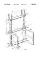
- FIG. 1is a perspective view of a wall mountable modular component mounting system according to the principles of the invention mounted on a room partition by partition hangers. The system is shown with a pair of rail racks in component mounting position.
- FIG. 2is a perspective view of the wall mountable modular component mounting system of FIG. 1, but without the rail racks. Also, wall mounts are shown in place; partition hangers are shown above in somewhat of an exploded view manner.
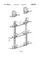
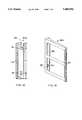
- FIG. 3is a perspective view of one of the rails shown in FIGS. 1-2.
- the railis shown with two laterally extending mounting brackets at its lower end.
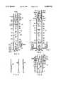
- FIG. 4is a rear elevation view of the rail shown in FIGS. 1-3.
- FIG. 5is a rear elevation view of a portion of the upper end of the rail shown in FIGS. 1-4.
- FIGS. 6(a), 6(b), and 6(c)are various showings of rail stiffeners used with the rails shown in FIGS. 1-5.
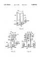
- FIG. 7is a perspective view of a portion of opposite ends of two rails shown in FIGS. 1-5 indicating movement to bring the mating element of one of the rails into interlocking engagement with the mating opening of another rail.
- FIG. 8illustrates the mating opening and elements of FIG. 7 in interlocking engagement.
- FIG. 9is a perspective view of a cross member stiffener shown in FIGS. 1-2.
- FIG. 10is a front elevation view, partly in cut away section, showing the cross member stiffener of FIG. 9. The cut away section is made to more clearly show the mating slot of the cross member stiffener.
- FIG. 11is a perspective view from the bottom of the cross member stiffener of FIGS. 9-10.
- FIG. 12is a perspective view of the partition hanger mount shown in FIGS. 1 and 2.
- FIG. 13is a perspective view of the wall hanger mount shown in FIG. 2;
- FIG. 14is a rear elevation view of the wall hanger mount shown in FIGS. 2 and 13.
- FIG. 15is a front elevation view of the left rail rack shown is FIG. 1.
- FIG. 16is a perspective view of the left rail rack shown in FIGS. 1 and 15.
- FIG. 17is a front elevation view of the modular component mounting system of FIG. 1 with a second set of rail racks in component mounting position.
- FIGS. 1 and 2show a modular component mounting system 10 according to the principles of the invention.
- the system 10includes two pairs of vertically oriented identical metal wall rails 12 interlocked at their opposite ends, horizontally oriented metal cross stiffener members 14 connecting the rails 12 in interlocking fashion, and two metal rack rails 16(a) and 16(b) (FIG. 1) are shown interlocked in mounted position on the lower rails 12 in position to receive an electronic component, such a router and bridges or patch panels.
- the system 10is shown in FIG. 1 mounted or hung by metal partition hangers 18 on a room partition 20, indicated in dashed lines.
- FIG. 2shows wall mounts 19 in mounting position and the partition hangers 18 are indicated above the system 10 out of mounting position. Additional wall racks 12 can be used as circumstances demand.
- FIGS. 3-5are enlarged showings of one of the wall rails 12 made of sheet steel that has a thickness "t" (see FIG. 5) of 0.060 of and inch. While the rail 12 and other components of the system 10 are made of sheet steel of the same thickness "t", other thicknesses can be used. Moreover, components can be made of other rigid material--such as plastic.
- Each of the rails 12is configured in such a manner at its ends that rails 12 an. interlock with each other at opposite ends.
- rail 12includes an elongated central portion 22 and an upstanding wall portion 24 at each of the longitudinal edges of the central portion 22.
- the upstanding wall portions 24extend away from the elongated central portion 22 on the same side of the rail 12 and as shown, the wall portions 24 have free upper edges that terminate in the same plane.
- the wall portions 24keep the central portion 22 in spaced apart relationship with a wall on which the system 10 is mounted.
- the central portion 22has opposing major surfaces 26 and 28 (see FIG. 5).
- the major surface 26is on the side of the rail 12 (central portion 22) opposite the upstanding wall portions 24 and is the outwardly facing surface when the system 10 is mounted on a wall; the major surface 28, the inward wall facing surface when the system 10 is mounted on a wall.
- the outwardly facing surface 26includes a main surface portion 30, an end surface portion 32 that is narrower in width than the main surface portion 30, and a transition surface portion 34.
- the end surface portion 32terminates one end of the rail 12.
- the end surface portion 32extends in a direction parallel to the main surface portion 30 and is laterally offset therefrom a distance substantially equal to the thickness dimension "t" of the sheet steel. The offset is in a direction that places the main surface portion 30 further from a wall than the end surface portion 32 when the rails 12 of the system 10 are mounted on a wall.
- the transition portion 34is relatively short and connects the adjacent ends of the offset end surface portion 32 and the main surface portion 30. As a result, the transition surface portion extends in inclined relationship with the portions 30 and 32.
- the angle of inclinationshown as ⁇ in FIG. 3, is 45 degrees, but can be inclined at different angles under other circumstances, such as between 45 and 90 degrees. Under some circumstances an inclination angle ⁇ of 90 degrees can conveniently be used.
- the opening 36is shaped to include an elongated central space 37 extending lengthwise on the longitudinal axis of the rail 12 and having a width "w" (see FIG. 4) and aligned rectangular mating or hanging slot 40(a) and rectangular mounting slot 40(b) of the same size communicating with the central space 37 at opposite sides of such space.
- the central space 37is generally rectangular in shape and defined by spaced apart parallel side edges 38 (a) and 38 (b) and slant edges 39 (a) , 39 (b) , 39 (c) , and 39 (d) each forming an angle ⁇ of 60 degrees (see FIG.
- the hanging slot 40 (a)is defined by spaced apart parallel side edges 41 (a) and 42 (a) and end edge 43 (a); the mounting slot 40 (b) , by spaced apart parallel side edges 41 (b) and 42 (b) and end edge 43(b).
- the pairs of side edges 41 (a) and 42 (a) , and the pairs of side edges 41 (b) and 42 (b)are both separated by a width distance "d" (see FIG. 4) that is smaller in dimension than the width dimension "w" of the central space 37.
- the central space 37is shown as rectangular, it can be other shapes, such as a square, an oval, or a circle.
- the hanging slot 40 (a)is situated entirely in the end surface portion 32 and the mounting slot 40(b) is situated entirely in the main surface portion 30.
- the central space 37is located in all the surface portions 30, 32, and 34.
- the parallel side edges 38(a) and 38(b)extend in the end surface portion 32, run across the transition surface portion 34, and terminate at the upper side of the transition surface portion 34 .
- the slant edges 39 (c) and 39(d)are located in the main surface portion 30.
- FIGS. 6(a)-6(b)show metal rail stiffeners 45 and 46, which are used on the rail 12 at the wall portions 24 to span between the surface portions 30, 32, and 34. As illustrated, the stiffeners 45 and 46 are welded to the inside of wall portions 24.
- the elongated central portion 22 of the rail 12has mating keyhole shaped openings 48 spaced apart along its longitudinal axis. These holes 48 are for interlock mounting rack rails 16 on rails 12 and each includes a circular part 50 and a slot 52 communicating with the circular part 50. As shown, the slots 52 are the same size as the slots 40 (a) and 40 (b).
- the elongated central portion 22 of the rail 12also includes a circular recess 54 with a hole 56 for screw fasting to a wall.
- the other end of the rail 12 from the end surface portion 32includes an inwardly extending mating elements 60 located on the longitudinal axis of the rail 12 that includes a platform plate 62 and generally rectangular shaped arms 64 and 66.
- the arms 64 and 66are curved to hold the plate 62 in spaced apart relation with respect to the main surface portion 30 of the inward wall facing surface 28.
- the span of the plate 62 "s"(see FIG. 8) is greater than the width dimension "d” separating the side edges 41 and 42 of the slots 40 (a) and 40 (b) .
- the portion of the plate 62 that extends outwardly of the width of the arms 64 and 66forms wings or wing portions (designed as "wings" in FIG.
- the distance or height "h" (see FIG. 2) of the underside surface of the plate 62 from the inward wall facing surface 28must be enough greater than the thickness "t" to allow interlocking of the wings of one rail 12 with the material at the edges 41 and 42 of the slot 40 (a) of another rail 12.
- the members of the system 10include additional mating elements 60 identical to the mating element 60 just described, except some of the elements are formed on the outwardly facing surface side of a member 60(a) ; some of the elements are formed on the inwardly facing surface of the member 60. It may be advantageous at times to use wings of various sizes and heights with slots of different widths.
- the end surface portion 32 of the railis sufficiently narrower in width than the width of the other end of the rail 12 to allow the inward wall facing surface 28 of the other end of one of the rails 12 to be placed in contact with the end surface portion 32 of another rail 12 so that the interlocking between the inwardly extending mating element 60 and the edge regions of a slot 40(a) can take place.
- the upstanding wall portions 24 at the other end of a rail 12 with the inwardly extending mating element 60are located in an outside immediate adjacent relationship with the upstanding wall portions 24 at the end surface portion end of the other rail 12.
- FIG. 7illustrates movement between opposite ends of two rails 12 to bring an inwardly extending mating element 60 on one of the rails 12 into interlocking engagement with the edges of a slot 40(a) in a second rail 12.
- the plate 62moves through the central space 37 of the opening 36.
- the two railsare moved relative to each other so that the plate 62 moves into the slot 40 (a) to establish an interlocking relationship between the plate 62 (wings) and the material of the rail 12 at the edges 41 (a) and 41 (b) of FIG. 8 illustrates interlocking engagement between inwardly extending mating element 60 and slot 40(a) .
- Patent application Ser. No. 08/016,010which discloses fastening between mating elements like mating element 60 and a mating slot, is hereby specifically incorporated herein by reference.
- FIGS. 9-11show the cross stiffener member 14 that includes a main portion 72, a lower channel portion comprising a lip 74 and a bottom 76, and two openings 78, one formed at each of the ends of the member 14.
- Each of the two opening 78includes a slot 80 defined by parallel spaced apart side edges 82 and 84 [spaced apart the same distance and the distance "d" as the side edges 41 and 42 of the slots 40(a) and 40 (b) ] and end edge 86.
- Each of the openingsfurther includes an entrance region defined by slant edges 88 and 89, parallel spaced apart edges 90 and 92, and an entrance slot 94 in the bottom 76 defined by end edges 96 and 98 and side edge 99 (see FIG. 11).
- the end edges 96 and 98 of the slot 94are greater in dimension than the thickness "t" of the material of rail 12 to allow the platform plate 62 of an inwardly extending mating element 60 of another member or rail to move through the entrance region of the opening 78 for mating engagement with the edge regions of slot 80.
- the slots 80 of the rail cross stiffener member 14interlock with the inwardly extending mating element 60 carried by laterally extending mounting brackets 100 and 102 (see FIGS. 1-5) of the rails 12.
- end rail stiffener 14 and rail 12are moved relative to each other to move plate 62 through slot 94 and entrance region to bring the plate into slot 80.
- the wings of the plate 62interlock with the material at the edge regions of slot 80 in a manner similar to what is shown in FIG. 8 in connection with interlocking the opposite ends of rails 12.
- Cross stiffener members 14 of different lengthscan be used as circumstances demand.
- FIG. 12shows the partition hanger 18 that is generally U-shaped and includes a front wall 102, a top 104, and a rear wall 106 shorter in length than the front wall 102.
- the front wallincludes laterally extending mounting brackets 110 and 112, which each includes an outwardly facing mating element 60(a) for interlocking engagement with a cross stiffening member in a slot 80. Additionally, at the bottom of the front wall 102 there is included an inwardly facing mating element 60 for interlocking engagement with a rail 12 in slot 40(a) of opening 36.
- FIGS. 13 and 14show the wall hanger 19 that is generally I-shaped and is configured identically to the upper end of rail 12 as viewed in FIGS. 1-4.
- the hanger 19includes an elongated central portion 122 and upstanding wall portions 124 at each of longitudinal edges of the central portion 122.
- the wall portions 124extend away from the central portion 122 on the same side of the hanger 19.
- the central portion 122has opposing major surfaces: an outwardly facing surface 126 when the system 10 is mounted on a wall and an inward wall facing surface (not shown) when the system 10 is mounted on a wall.
- the outwardly facing surface 126includes a main surface portion 130 that has the same width dimension as the main surface portion 30, an end surface portion 132 that is the same width and length dimensions as the end surface portion 32 of the rail 12, and a transition surface portion 134 that is the same width and length dimensions as the transition surface portion 34.
- the end surface portion 132extends in a direction parallel to the main surface portion 130 and is laterally offset therefrom a distance substantially equal to the thickness dimension "t".
- the transition surface portion 132extends in inclined relationship with the portions 130 and 134.
- the angle of inclinationcan vary like the angle of inclination ⁇ shown in FIG. 3 and discussed in connection with rail 12.
- the end surface portion 132 of the hanger 19includes an opening 136 similar to the opening 36 in the rail 12.
- the opening 136is shaped to include a generally rectangular space 137 extending lengthwise along the longitudinal axis of the hanger 19 and having a width dimension that is the same as the width dimension "w" of the central space 37.
- the space 137is located entirely in the end surface region 132 and is defined by spaced apart parallel side edges 138(a) and 138(b), end edge 138(c), and slant edges 139(a) and 139(b).
- the opening 136further includes a generally rectangular slot 140 communicating with the upper side of the space 137 that extends lengthwise along the longitudinal axis of the hanger 19.
- the slot 140is located entirely in the end surface portion 132 and is defined by spaced apart parallel side edges 141 and 142 and end edge 143.
- the width dimension of the slot 140is the same as the width dimension "d" of the slots 40 (a) and 40(b) of rail 12.
- Hanger 19further includes laterally extending mounting brackets 150 and 152, which each includes an outwardly facing mating element 60(a) for interlocking engagement with a cross stiffening member 14. Additionally, at the bottom of the hanger 19 there is an inwardly facing mating element 60 for interlocking engagement with a rail 12 in slot 40 (a) of the opening 36.
- FIGS. 15 and 16show the left rail rack 16(a), which includes a back member 160, a side member, and a mounting flange 164 having mounting openings 166.
- the back member 160 and mounting flange 164extend at right angles laterally away from the side member 160 on opposite sides thereof.
- the back memberincludes spaced apart inwardly facing mating members 60 at opposite ends thereof for interlocking engagement with mounting slot 40 (b) of the hanging/mounting opening 36 and with the mounting slot 52 of the opening 48 to mount the rail rack 16(a) on a rail 12 of the system 10.
- the distance "x"see FIG.
- the component mounting system 10includes uninterrupted vertically aligned mounting of rail racks 16. This feature is illustrated in FIG. 17, which shows the system 10 with four mounted rail racks-racks 16(a), 16(b), 16(c), and 16(d). This closely spaced vertical relationship is accomplished by the relationship between the mounting openings of rails 12 and the location of the inwardly extending mating elements 60 of the side member 160.
- the distance between the end edge 53 of the bottom mounting slot 52 of one rail 12 and the end edge 43(b) of the hanging/mounting opening 36 of a second interlocked rail 12(shown as "Y” in FIG. 2) is twice the distance between the mid-region of the inwardly extending mating elements 60 of rail rack 160 and its associated rail rack end (shown as "y” in FIG. 15).
- brackets 100, 102,110, and 112variations can be made as circumstances demand.
- single bracketscan be used, e.g., only bracket 102 in the case of rails 12.
- the outside rail 100is used for outside mounting to add more rails 12 or to mount covers or enclosures on the system 10.
Landscapes
- Engineering & Computer Science (AREA)
- Power Engineering (AREA)
- Architecture (AREA)
- Civil Engineering (AREA)
- Structural Engineering (AREA)
- Support Devices For Sliding Doors (AREA)
Abstract
Description
Claims (7)
Priority Applications (1)
| Application Number | Priority Date | Filing Date | Title |
|---|---|---|---|
| US08/237,517US5485932A (en) | 1994-05-03 | 1994-05-03 | Wall mountable modular component mounting system |
Applications Claiming Priority (1)
| Application Number | Priority Date | Filing Date | Title |
|---|---|---|---|
| US08/237,517US5485932A (en) | 1994-05-03 | 1994-05-03 | Wall mountable modular component mounting system |
Publications (1)
| Publication Number | Publication Date |
|---|---|
| US5485932Atrue US5485932A (en) | 1996-01-23 |
Family
ID=22894062
Family Applications (1)
| Application Number | Title | Priority Date | Filing Date |
|---|---|---|---|
| US08/237,517Expired - LifetimeUS5485932A (en) | 1994-05-03 | 1994-05-03 | Wall mountable modular component mounting system |
Country Status (1)
| Country | Link |
|---|---|
| US (1) | US5485932A (en) |
Cited By (63)
| Publication number | Priority date | Publication date | Assignee | Title |
|---|---|---|---|---|
| US5687856A (en)* | 1996-03-26 | 1997-11-18 | Kendrena; Ken | Tool and implement hanging system |
| US5988409A (en)* | 1995-07-21 | 1999-11-23 | Industrial Wire Products, Inc. | Vertical wall rack and variable shelf arrangement |
| US6109461A (en)* | 1996-07-01 | 2000-08-29 | John Sterling Corporation | Shelf mounting system including mounting brackets having mounting ears for mounting vertical track members to a wall |
| US6161709A (en)* | 1999-08-13 | 2000-12-19 | John Sterling Corporation | Suspended shelf mounting system |
| US6201687B1 (en) | 1998-10-09 | 2001-03-13 | American Access Technologies, Inc. | Modular furniture wall system and method for telecommunications equipment and wire management in an open office architecture |
| US6364260B1 (en) | 1998-02-26 | 2002-04-02 | Moore Push-Pin Company | Reusable single part bend to grip partition and door hardware |
| US6439404B1 (en)* | 1998-08-05 | 2002-08-27 | Nicolas Steeg | Multipurpose support |
| US6499608B1 (en) | 2000-02-14 | 2002-12-31 | John Sterling Corporation | Wall-mounted storage system |
| US6622873B2 (en) | 2001-06-20 | 2003-09-23 | International Business Machines Corporation | Self-aligning, single person installable rack rail/alignment plate assembly |
| US20030234231A1 (en)* | 2002-06-21 | 2003-12-25 | Tony Rowe | Storage system |
| US20040038568A1 (en)* | 2002-07-09 | 2004-02-26 | Woolsey Terrill L. | Selectable keying device |
| US20040173550A1 (en)* | 2003-03-04 | 2004-09-09 | Adams William E. | Door hook with interlocking hook segments |
| US20050279898A1 (en)* | 2004-06-21 | 2005-12-22 | Sweere Harry C | Wall mount system and method |
| US20080087619A1 (en)* | 2006-10-13 | 2008-04-17 | Kim Laney | Space saving hat and purse storage device |
| US20090078664A1 (en)* | 2007-09-26 | 2009-03-26 | Steffan Steven D | Display rack |
| US20090090686A1 (en)* | 2004-12-30 | 2009-04-09 | Edsal Manufacturing Co., Inc. | Shelving connector |
| US20090139943A1 (en)* | 2007-12-04 | 2009-06-04 | Clairson, Inc. | Standard and track shelving systems |
| US20090179111A1 (en)* | 2006-04-06 | 2009-07-16 | The Boeing Company | Interior panel attachment system |
| US7637255B1 (en)* | 2007-02-28 | 2009-12-29 | Freeland John P | Target launcher having versatile mounting configurations |
| US20100155350A1 (en)* | 2008-12-18 | 2010-06-24 | Ivan Kaplan | Wall-hanging snap-in organizer device |
| US20100326940A1 (en)* | 2009-06-25 | 2010-12-30 | Mark John Donohoe | Shelving system |
| US20110036856A1 (en)* | 2009-08-14 | 2011-02-17 | Van Ooyen Wes | Rack arrangement for kiosk dispenser |
| US20110192810A1 (en)* | 2010-02-08 | 2011-08-11 | Jui-Chien Kao | Hanging assembly for a tool cabinet |
| US20110253861A1 (en)* | 2010-05-14 | 2011-10-20 | Kressin Matthew S | Over-the-door hanging apparatus |
| US20110253852A1 (en)* | 2010-04-16 | 2011-10-20 | Brendan Whelan | Hand rail mounting bracket for an electrical panel |
| USD647634S1 (en) | 2010-05-28 | 2011-10-25 | Steelcase Inc. | Frame assembly frame member |
| US20120085785A1 (en)* | 2009-10-07 | 2012-04-12 | Delaware Capital Formation, Inc. | Modular chemical dispensing system and methods |
| US20120132766A1 (en)* | 2010-11-29 | 2012-05-31 | Fowler Robert B | Article holder adapted for being supported by a fence |
| USD668945S1 (en) | 2011-04-08 | 2012-10-16 | Clairson, Inc. | Track for a shelving system |
| US20120306335A1 (en)* | 2011-06-03 | 2012-12-06 | Kendall Howard L.L.C. | Corner-Mount Electronics Cabinet |
| US20130091689A1 (en)* | 2011-10-17 | 2013-04-18 | Robert H. Mimlitch, III | Wall-Mountable Support Rack for Equipment |
| US8434629B2 (en) | 2011-04-08 | 2013-05-07 | Clairson Inc. | Adjustable shelving system with overlapping tracks |
| US8646624B2 (en) | 2007-12-04 | 2014-02-11 | Clairson, Inc. | Standard and track shelving systems |
| US20160088939A1 (en)* | 2012-11-08 | 2016-03-31 | Karen Y. Lamb | Retrofitable hanging frame |
| WO2016093796A1 (en)* | 2014-12-09 | 2016-06-16 | Hewlett Packard Enterprise Development Lp | Interlock bracket unit |
| US9386867B2 (en) | 2010-05-14 | 2016-07-12 | Mcs Industries, Inc. | Over-the-door hanging apparatus |
| US20160248233A1 (en)* | 2015-02-20 | 2016-08-25 | Crenlo Cab Products, Inc. | Precision Mounting System for Wall Mounted Electrical Enclosure |
| US9480350B2 (en) | 2010-05-14 | 2016-11-01 | Mcs Industries, Inc. | Over-the-door hanging apparatus |
| CN106837962A (en)* | 2015-12-04 | 2017-06-13 | 欧洲公司 | Wall equipment and the method for installing wall equipment |
| US20170172322A1 (en)* | 2015-12-22 | 2017-06-22 | Wal-Mart Stores, Inc. | Bagging station support frame and method of forming the same |
| US9801478B1 (en) | 2010-05-14 | 2017-10-31 | Mcs Industries, Inc. | Over-the-door hanging apparatus |
| US10028597B2 (en) | 2015-12-22 | 2018-07-24 | Walmart Apollo, Llc | Bagging station support frame and method of forming the same |
| US10086967B2 (en) | 2016-11-28 | 2018-10-02 | Walmart Apollo, Llc | Retractable bagging station |
| US20180338609A1 (en)* | 2017-05-23 | 2018-11-29 | April M. Mitchell | Adjustment mechanism for over-door hanging system and method of use |
| US10238221B2 (en) | 2010-05-14 | 2019-03-26 | Mcs Industries, Inc. | Over-the-door hanging apparatus |
| US10681995B2 (en) | 2016-06-23 | 2020-06-16 | Mcs Industries, Inc. | Hanging apparatus and bracket for hanging a frame apparatus |
| US10835061B2 (en) | 2010-05-14 | 2020-11-17 | Mcs Industries, Inc. | Over the door mirror apparatus |
| US10959546B2 (en) | 2010-05-14 | 2021-03-30 | Mcs Industries, Inc. | Over-the-door hanging apparatus |
| US11246431B2 (en) | 2016-06-23 | 2022-02-15 | Mcs Industries, Inc. | Hanging apparatus and bracket thereof |
| US11267491B2 (en)* | 2018-08-14 | 2022-03-08 | Cattron North America, Inc. | Assemblies for mounting portable remote control locomotive (RCL) systems to locomotive handrailing |
| US20230092850A1 (en)* | 2021-09-17 | 2023-03-23 | Peter E. Wiggin | Deck rail shelf |
| US20230129296A1 (en)* | 2021-10-27 | 2023-04-27 | Edsal Manufacturing Company, Llc | Weldless shelf support beams and shelving units utilizing same |
| USD993164S1 (en)* | 2019-06-27 | 2023-07-25 | Unirac Inc. | Bracket |
| USD993163S1 (en)* | 2019-08-02 | 2023-07-25 | Unirac Inc. | Bracket |
| US20230407640A1 (en)* | 2021-09-17 | 2023-12-21 | Peter E. Wiggin | Deck rail shelf |
| US20240065458A1 (en)* | 2022-08-29 | 2024-02-29 | Williams Scotsman, Inc. | Modular storage system for storage containers |
| US20240138567A1 (en)* | 2022-10-26 | 2024-05-02 | Changsha Yuepu Children's Products Co., Ltd. | Over-the-door organizer |
| USD1054595S1 (en) | 2022-01-26 | 2024-12-17 | Mcs Industries, Inc. | Connector for molding |
| USD1057216S1 (en) | 2022-01-26 | 2025-01-07 | Mcs Industries, Inc. | Molding |
| US12305407B2 (en) | 2022-01-26 | 2025-05-20 | Mcs Industries, Inc. | Decorative moulding assembly and method of manufacturing and assembling the same |
| US12310495B2 (en)* | 2021-10-27 | 2025-05-27 | Edsal Manufacturing Company, Llc | Weldless shelf support beams and shelving units utilizing same |
| US12390026B1 (en)* | 2024-02-02 | 2025-08-19 | Catherine A. Martinez | Document hanger |
| USD1097994S1 (en) | 2025-07-11 | 2025-10-14 | Unirac, Inc. | Bracket |
Citations (20)
| Publication number | Priority date | Publication date | Assignee | Title |
|---|---|---|---|---|
| US2428073A (en)* | 1945-09-24 | 1947-09-30 | Stanley T Handel | Rack mounting means |
| US2858265A (en)* | 1955-10-21 | 1958-10-28 | Schneider Max Stefan | Plating rack |
| US2858266A (en)* | 1957-05-15 | 1958-10-28 | Max S Schneider | Plating rack |
| US3142386A (en)* | 1960-04-15 | 1964-07-28 | Paltier Corp | Pallet rack |
| US3156282A (en)* | 1962-02-08 | 1964-11-10 | Thompson Bremer & Company | Sheet metal fastener with t-shaped key |
| FR1378230A (en)* | 1963-10-03 | 1964-11-13 | Mills Const Sa | Device for assembling metal construction elements |
| US3198343A (en)* | 1963-04-10 | 1965-08-03 | Gordon J Pollock | Storage rack |
| US3208778A (en)* | 1962-10-04 | 1965-09-28 | Storack Corp | Interlocking structural members |
| US3358848A (en)* | 1966-03-16 | 1967-12-19 | Eth Maskin Ab | Vertically adjustable supporting means |
| US3499672A (en)* | 1966-08-08 | 1970-03-10 | Dexion Ltd | Connections between structural components |
| US3705653A (en)* | 1971-04-13 | 1972-12-12 | Armand J Pereyra | Necktie rack |
| US3881829A (en)* | 1972-11-27 | 1975-05-06 | Dexion Comino Int Ltd | Connections between structural components |
| US3921365A (en)* | 1974-10-04 | 1975-11-25 | Armstrong Cork Co | Joint structure for suspended ceiling system member |
| US4106630A (en)* | 1977-04-28 | 1978-08-15 | Parsteel Products Company, Inc. | Storage rack assembly |
| US4138019A (en)* | 1975-03-20 | 1979-02-06 | Frito-Lay, Inc. | Mounting device |
| US4165944A (en)* | 1977-07-28 | 1979-08-28 | Dexion-Comino International Limited | Connection means for structures |
| US4549665A (en)* | 1982-09-03 | 1985-10-29 | Republic Steel Corporation | Shelf assembly |
| USD317750S (en) | 1987-09-04 | 1991-06-25 | Digital Equipment Corporation | Patch panel |
| US5148353A (en)* | 1990-06-29 | 1992-09-15 | Digital Equipment Corporation | Mounting system for installation of communication boxes having a convex bottom post and a rigid top post |
| US5333744A (en)* | 1993-02-10 | 1994-08-02 | Digital Equipment Corporation | Modular equipment support system |
- 1994
- 1994-05-03USUS08/237,517patent/US5485932A/ennot_activeExpired - Lifetime
Patent Citations (20)
| Publication number | Priority date | Publication date | Assignee | Title |
|---|---|---|---|---|
| US2428073A (en)* | 1945-09-24 | 1947-09-30 | Stanley T Handel | Rack mounting means |
| US2858265A (en)* | 1955-10-21 | 1958-10-28 | Schneider Max Stefan | Plating rack |
| US2858266A (en)* | 1957-05-15 | 1958-10-28 | Max S Schneider | Plating rack |
| US3142386A (en)* | 1960-04-15 | 1964-07-28 | Paltier Corp | Pallet rack |
| US3156282A (en)* | 1962-02-08 | 1964-11-10 | Thompson Bremer & Company | Sheet metal fastener with t-shaped key |
| US3208778A (en)* | 1962-10-04 | 1965-09-28 | Storack Corp | Interlocking structural members |
| US3198343A (en)* | 1963-04-10 | 1965-08-03 | Gordon J Pollock | Storage rack |
| FR1378230A (en)* | 1963-10-03 | 1964-11-13 | Mills Const Sa | Device for assembling metal construction elements |
| US3358848A (en)* | 1966-03-16 | 1967-12-19 | Eth Maskin Ab | Vertically adjustable supporting means |
| US3499672A (en)* | 1966-08-08 | 1970-03-10 | Dexion Ltd | Connections between structural components |
| US3705653A (en)* | 1971-04-13 | 1972-12-12 | Armand J Pereyra | Necktie rack |
| US3881829A (en)* | 1972-11-27 | 1975-05-06 | Dexion Comino Int Ltd | Connections between structural components |
| US3921365A (en)* | 1974-10-04 | 1975-11-25 | Armstrong Cork Co | Joint structure for suspended ceiling system member |
| US4138019A (en)* | 1975-03-20 | 1979-02-06 | Frito-Lay, Inc. | Mounting device |
| US4106630A (en)* | 1977-04-28 | 1978-08-15 | Parsteel Products Company, Inc. | Storage rack assembly |
| US4165944A (en)* | 1977-07-28 | 1979-08-28 | Dexion-Comino International Limited | Connection means for structures |
| US4549665A (en)* | 1982-09-03 | 1985-10-29 | Republic Steel Corporation | Shelf assembly |
| USD317750S (en) | 1987-09-04 | 1991-06-25 | Digital Equipment Corporation | Patch panel |
| US5148353A (en)* | 1990-06-29 | 1992-09-15 | Digital Equipment Corporation | Mounting system for installation of communication boxes having a convex bottom post and a rigid top post |
| US5333744A (en)* | 1993-02-10 | 1994-08-02 | Digital Equipment Corporation | Modular equipment support system |
Non-Patent Citations (1)
| Title |
|---|
| U.S. Ser. No. 08/016,010 to LoCicero et al. filed Feb. 10, 1993.* |
Cited By (115)
| Publication number | Priority date | Publication date | Assignee | Title |
|---|---|---|---|---|
| US5988409A (en)* | 1995-07-21 | 1999-11-23 | Industrial Wire Products, Inc. | Vertical wall rack and variable shelf arrangement |
| US5687856A (en)* | 1996-03-26 | 1997-11-18 | Kendrena; Ken | Tool and implement hanging system |
| US6109461A (en)* | 1996-07-01 | 2000-08-29 | John Sterling Corporation | Shelf mounting system including mounting brackets having mounting ears for mounting vertical track members to a wall |
| US6179136B1 (en)* | 1996-07-01 | 2001-01-30 | John Sterling Corporation | Shelf mounting system |
| US6364260B1 (en) | 1998-02-26 | 2002-04-02 | Moore Push-Pin Company | Reusable single part bend to grip partition and door hardware |
| US6439404B1 (en)* | 1998-08-05 | 2002-08-27 | Nicolas Steeg | Multipurpose support |
| US6201687B1 (en) | 1998-10-09 | 2001-03-13 | American Access Technologies, Inc. | Modular furniture wall system and method for telecommunications equipment and wire management in an open office architecture |
| US6161709A (en)* | 1999-08-13 | 2000-12-19 | John Sterling Corporation | Suspended shelf mounting system |
| US6499608B1 (en) | 2000-02-14 | 2002-12-31 | John Sterling Corporation | Wall-mounted storage system |
| US6622873B2 (en) | 2001-06-20 | 2003-09-23 | International Business Machines Corporation | Self-aligning, single person installable rack rail/alignment plate assembly |
| US20030234231A1 (en)* | 2002-06-21 | 2003-12-25 | Tony Rowe | Storage system |
| US6932225B2 (en)* | 2002-06-21 | 2005-08-23 | Newell Limited | Storage system |
| US20040038568A1 (en)* | 2002-07-09 | 2004-02-26 | Woolsey Terrill L. | Selectable keying device |
| US7204371B2 (en)* | 2002-07-09 | 2007-04-17 | Lsi Logic Corporation | Selectable keying device |
| US20040173550A1 (en)* | 2003-03-04 | 2004-09-09 | Adams William E. | Door hook with interlocking hook segments |
| US6854610B2 (en)* | 2003-03-04 | 2005-02-15 | Adams Mfg. Corp. | Door hook with interlocking hook segments |
| US20050279898A1 (en)* | 2004-06-21 | 2005-12-22 | Sweere Harry C | Wall mount system and method |
| US20090090686A1 (en)* | 2004-12-30 | 2009-04-09 | Edsal Manufacturing Co., Inc. | Shelving connector |
| US8458979B2 (en)* | 2006-04-06 | 2013-06-11 | The Boeing Company | Interior panel attachment system |
| US20090179111A1 (en)* | 2006-04-06 | 2009-07-16 | The Boeing Company | Interior panel attachment system |
| US20080087618A1 (en)* | 2006-10-13 | 2008-04-17 | Kim Laney | Space saving hat and purse storage device |
| US20080087619A1 (en)* | 2006-10-13 | 2008-04-17 | Kim Laney | Space saving hat and purse storage device |
| US7637255B1 (en)* | 2007-02-28 | 2009-12-29 | Freeland John P | Target launcher having versatile mounting configurations |
| US20090078664A1 (en)* | 2007-09-26 | 2009-03-26 | Steffan Steven D | Display rack |
| US7900783B2 (en)* | 2007-12-04 | 2011-03-08 | Clairson, Inc. | Standard and track shelving systems |
| US8646624B2 (en) | 2007-12-04 | 2014-02-11 | Clairson, Inc. | Standard and track shelving systems |
| US20090139943A1 (en)* | 2007-12-04 | 2009-06-04 | Clairson, Inc. | Standard and track shelving systems |
| US7938279B2 (en)* | 2008-12-18 | 2011-05-10 | Ivan Kaplan | Wall-hanging snap-in organizer device |
| US20100155350A1 (en)* | 2008-12-18 | 2010-06-24 | Ivan Kaplan | Wall-hanging snap-in organizer device |
| US20100326940A1 (en)* | 2009-06-25 | 2010-12-30 | Mark John Donohoe | Shelving system |
| US8517189B2 (en)* | 2009-06-25 | 2013-08-27 | Mark John Donohoe | Shelving system |
| US20110036856A1 (en)* | 2009-08-14 | 2011-02-17 | Van Ooyen Wes | Rack arrangement for kiosk dispenser |
| US8191719B2 (en)* | 2009-08-14 | 2012-06-05 | Pcas Patient Care Automation Services Inc. | Rack arrangement for kiosk dispenser |
| US8695814B2 (en)* | 2009-08-14 | 2014-04-15 | Medavail, Inc. | Rack arrangement for kiosk dispenser |
| US20120085785A1 (en)* | 2009-10-07 | 2012-04-12 | Delaware Capital Formation, Inc. | Modular chemical dispensing system and methods |
| US9096417B2 (en)* | 2009-10-07 | 2015-08-04 | Delaware Capital Formation, Inc. | Modular chemical dispensing system and methods |
| US20110192810A1 (en)* | 2010-02-08 | 2011-08-11 | Jui-Chien Kao | Hanging assembly for a tool cabinet |
| US20110253852A1 (en)* | 2010-04-16 | 2011-10-20 | Brendan Whelan | Hand rail mounting bracket for an electrical panel |
| US8413938B2 (en)* | 2010-04-16 | 2013-04-09 | Brendan Whelan | Hand rail mounting bracket for an electrical panel |
| US9060627B2 (en) | 2010-05-14 | 2015-06-23 | Mcs Industries, Inc. | Over-the-door hanging apparatus |
| US11744390B2 (en) | 2010-05-14 | 2023-09-05 | Mcs Industries, Inc. | Hanging apparatus |
| US10835061B2 (en) | 2010-05-14 | 2020-11-17 | Mcs Industries, Inc. | Over the door mirror apparatus |
| US10959546B2 (en) | 2010-05-14 | 2021-03-30 | Mcs Industries, Inc. | Over-the-door hanging apparatus |
| US11033125B2 (en) | 2010-05-14 | 2021-06-15 | Mcs Industries, Inc. | Hanging apparatus |
| US8534627B2 (en)* | 2010-05-14 | 2013-09-17 | Mcs Industries, Inc. | Over-the-door hanging apparatus |
| US9801478B1 (en) | 2010-05-14 | 2017-10-31 | Mcs Industries, Inc. | Over-the-door hanging apparatus |
| US9480350B2 (en) | 2010-05-14 | 2016-11-01 | Mcs Industries, Inc. | Over-the-door hanging apparatus |
| US10080448B2 (en) | 2010-05-14 | 2018-09-25 | Mcs Industries, Inc. | Over-the-door hanging apparatus |
| US8746644B2 (en) | 2010-05-14 | 2014-06-10 | Mcs Industries, Inc. | Over-the-door hanging apparatus |
| US11419437B2 (en) | 2010-05-14 | 2022-08-23 | Mcs Industries, Inc. | Hanging apparatus |
| US20110253861A1 (en)* | 2010-05-14 | 2011-10-20 | Kressin Matthew S | Over-the-door hanging apparatus |
| US10238221B2 (en) | 2010-05-14 | 2019-03-26 | Mcs Industries, Inc. | Over-the-door hanging apparatus |
| US9622600B2 (en) | 2010-05-14 | 2017-04-18 | Mcs Industries, Inc. | Over-the-door hanging apparatus |
| US12408772B2 (en) | 2010-05-14 | 2025-09-09 | Mcs Industries, Inc. | Hanging apparatus |
| US9386867B2 (en) | 2010-05-14 | 2016-07-12 | Mcs Industries, Inc. | Over-the-door hanging apparatus |
| US11771245B1 (en) | 2010-05-14 | 2023-10-03 | Mcs Industries, Inc. | Hanging apparatus |
| USD647634S1 (en) | 2010-05-28 | 2011-10-25 | Steelcase Inc. | Frame assembly frame member |
| US20120132766A1 (en)* | 2010-11-29 | 2012-05-31 | Fowler Robert B | Article holder adapted for being supported by a fence |
| US8251331B2 (en)* | 2010-11-29 | 2012-08-28 | Robert B Fowler | Article holder adapted for being supported by a fence |
| USD668945S1 (en) | 2011-04-08 | 2012-10-16 | Clairson, Inc. | Track for a shelving system |
| US8434629B2 (en) | 2011-04-08 | 2013-05-07 | Clairson Inc. | Adjustable shelving system with overlapping tracks |
| US8894161B2 (en)* | 2011-06-03 | 2014-11-25 | Kendall Howard L.L.C. | Corner-mount electronics cabinet |
| US20120306335A1 (en)* | 2011-06-03 | 2012-12-06 | Kendall Howard L.L.C. | Corner-Mount Electronics Cabinet |
| US8913393B2 (en)* | 2011-10-17 | 2014-12-16 | Innovation First, Inc. | Wall-mountable support rack for equipment |
| US20130091689A1 (en)* | 2011-10-17 | 2013-04-18 | Robert H. Mimlitch, III | Wall-Mountable Support Rack for Equipment |
| US20160088939A1 (en)* | 2012-11-08 | 2016-03-31 | Karen Y. Lamb | Retrofitable hanging frame |
| TWI566669B (en)* | 2014-12-09 | 2017-01-11 | 慧與發展有限責任合夥企業 | Interlock bracket unit |
| US10080303B2 (en) | 2014-12-09 | 2018-09-18 | Hewlett Packard Enterprise Development Lp | Interlock bracket unit |
| WO2016093796A1 (en)* | 2014-12-09 | 2016-06-16 | Hewlett Packard Enterprise Development Lp | Interlock bracket unit |
| US20160248233A1 (en)* | 2015-02-20 | 2016-08-25 | Crenlo Cab Products, Inc. | Precision Mounting System for Wall Mounted Electrical Enclosure |
| CN106837962A (en)* | 2015-12-04 | 2017-06-13 | 欧洲公司 | Wall equipment and the method for installing wall equipment |
| US10028597B2 (en) | 2015-12-22 | 2018-07-24 | Walmart Apollo, Llc | Bagging station support frame and method of forming the same |
| US9844283B2 (en)* | 2015-12-22 | 2017-12-19 | Wal-Mart Stores, Inc. | Bagging station support frame and method of forming the same |
| US20170172322A1 (en)* | 2015-12-22 | 2017-06-22 | Wal-Mart Stores, Inc. | Bagging station support frame and method of forming the same |
| US10681995B2 (en) | 2016-06-23 | 2020-06-16 | Mcs Industries, Inc. | Hanging apparatus and bracket for hanging a frame apparatus |
| US11246431B2 (en) | 2016-06-23 | 2022-02-15 | Mcs Industries, Inc. | Hanging apparatus and bracket thereof |
| US10086967B2 (en) | 2016-11-28 | 2018-10-02 | Walmart Apollo, Llc | Retractable bagging station |
| US10512325B2 (en)* | 2017-05-23 | 2019-12-24 | April M. Mitchell | Adjustment mechanism for over-door hanging system and method of use |
| US20180338609A1 (en)* | 2017-05-23 | 2018-11-29 | April M. Mitchell | Adjustment mechanism for over-door hanging system and method of use |
| US11267491B2 (en)* | 2018-08-14 | 2022-03-08 | Cattron North America, Inc. | Assemblies for mounting portable remote control locomotive (RCL) systems to locomotive handrailing |
| USD1084975S1 (en) | 2019-06-27 | 2025-07-22 | Unirac, Inc. | Bracket |
| USD993164S1 (en)* | 2019-06-27 | 2023-07-25 | Unirac Inc. | Bracket |
| USD1059261S1 (en) | 2019-06-27 | 2025-01-28 | Unirac, Inc. | Bracket |
| USD993163S1 (en)* | 2019-08-02 | 2023-07-25 | Unirac Inc. | Bracket |
| USD1086018S1 (en) | 2019-08-02 | 2025-07-29 | Unirac, Inc. | Bracket |
| USD1062597S1 (en) | 2019-08-02 | 2025-02-18 | Unirac, Inc. | Bracket |
| US12188237B2 (en)* | 2021-09-17 | 2025-01-07 | Peter E. Wiggin | Deck rail shelf |
| US20230407640A1 (en)* | 2021-09-17 | 2023-12-21 | Peter E. Wiggin | Deck rail shelf |
| US11744366B2 (en)* | 2021-09-17 | 2023-09-05 | Peter E. Wiggin | Deck rail shelf |
| US20230092850A1 (en)* | 2021-09-17 | 2023-03-23 | Peter E. Wiggin | Deck rail shelf |
| US12310495B2 (en)* | 2021-10-27 | 2025-05-27 | Edsal Manufacturing Company, Llc | Weldless shelf support beams and shelving units utilizing same |
| US11925258B2 (en)* | 2021-10-27 | 2024-03-12 | Edsal Manufacturing Company, Llc | Weldless shelf support beams and shelving units utilizing same |
| US20230129296A1 (en)* | 2021-10-27 | 2023-04-27 | Edsal Manufacturing Company, Llc | Weldless shelf support beams and shelving units utilizing same |
| USD1057216S1 (en) | 2022-01-26 | 2025-01-07 | Mcs Industries, Inc. | Molding |
| US12305407B2 (en) | 2022-01-26 | 2025-05-20 | Mcs Industries, Inc. | Decorative moulding assembly and method of manufacturing and assembling the same |
| USD1054595S1 (en) | 2022-01-26 | 2024-12-17 | Mcs Industries, Inc. | Connector for molding |
| USD1086502S1 (en) | 2022-01-26 | 2025-07-29 | Mcs Industries, Inc. | Connector for molding |
| USD1087400S1 (en) | 2022-01-26 | 2025-08-05 | Mcs Industries, Inc. | Molding |
| US20240065458A1 (en)* | 2022-08-29 | 2024-02-29 | Williams Scotsman, Inc. | Modular storage system for storage containers |
| US12310516B2 (en)* | 2022-08-29 | 2025-05-27 | Williams Scotsman, Inc. | Modular storage system for storage containers |
| US12022947B2 (en)* | 2022-10-26 | 2024-07-02 | Changsha Yuepu Children's Products Co., Ltd. | Over-the-door organizer |
| US20240138567A1 (en)* | 2022-10-26 | 2024-05-02 | Changsha Yuepu Children's Products Co., Ltd. | Over-the-door organizer |
| US12390026B1 (en)* | 2024-02-02 | 2025-08-19 | Catherine A. Martinez | Document hanger |
| USD1098500S1 (en) | 2024-11-04 | 2025-10-14 | Mcs Industries, Inc. | Connector for molding |
| USD1098501S1 (en) | 2024-11-18 | 2025-10-14 | Mcs Industries, Inc. | Molding |
| USD1097994S1 (en) | 2025-07-11 | 2025-10-14 | Unirac, Inc. | Bracket |
| USD1097990S1 (en) | 2025-07-11 | 2025-10-14 | Unirac, Inc. | Bracket |
| USD1097993S1 (en) | 2025-07-11 | 2025-10-14 | Unirac, Inc. | Bracket |
| USD1097992S1 (en) | 2025-07-11 | 2025-10-14 | Unirac, Inc. | Bracket |
| USD1097991S1 (en) | 2025-07-11 | 2025-10-14 | Unirac, Inc. | Bracket |
| USD1097989S1 (en) | 2025-07-11 | 2025-10-14 | Unirac, Inc. | Bracket |
| USD1097997S1 (en) | 2025-07-11 | 2025-10-14 | Unirac, Inc. | Bracket |
| USD1097995S1 (en) | 2025-07-11 | 2025-10-14 | Unirac, Inc. | Bracket |
| USD1097988S1 (en) | 2025-07-11 | 2025-10-14 | Unirac, Inc. | Bracket |
| USD1097996S1 (en) | 2025-07-11 | 2025-10-14 | Unirac, Inc. | Bracket |
Similar Documents
| Publication | Publication Date | Title |
|---|---|---|
| US5485932A (en) | Wall mountable modular component mounting system | |
| US5542549A (en) | Cross connect frame for communication connector blocks and other devices | |
| US6073399A (en) | Post and beam supported slatwall | |
| CA2261931C (en) | Wall panel system | |
| US6497395B1 (en) | Mounting bracket | |
| EP0576642B1 (en) | Sub-panel guide system for electrical enclosures | |
| US6019331A (en) | Cantilever bracket assembly | |
| US5326162A (en) | Rack for a control cabinet | |
| US6711871B2 (en) | Wall panel with off-module components | |
| US6276103B1 (en) | Cover panel brace for partition systems | |
| EP0200514B1 (en) | Improvements in office screens and partitions | |
| CA1174642A (en) | Support rail | |
| US6009675A (en) | Knock-down portable partition system | |
| US5695263A (en) | Cabinet | |
| US6546684B2 (en) | Partition panel | |
| US3449877A (en) | Space divider | |
| US8033059B2 (en) | Paneling system | |
| CA2247535C (en) | Earthquake resistant enclosure for electronic equipment | |
| NZ230837A (en) | Demountable partition system horizontal runners support furniture and cables | |
| US6178702B1 (en) | Flexible light seal for partition systems | |
| GB1460321A (en) | Furniture systems | |
| US7350884B2 (en) | Tray with integrated rail guides for facilitating installation of equipment units into a cabinet rack | |
| US6029832A (en) | Frame assembly | |
| CA1284715C (en) | Intersecting partitions adapted to support corner-mounted furniture | |
| US5251413A (en) | Stabilized space dividing frames and panels |
Legal Events
| Date | Code | Title | Description |
|---|---|---|---|
| AS | Assignment | Owner name:DIGITAL EQUIPMENT CORPORATION, MASSACHUSETTS Free format text:ASSIGNMENT OF ASSIGNORS INTEREST;ASSIGNORS:ROMM, MICHAEL;BARKER, ROBERT;MORGAN, STUART K.;REEL/FRAME:007003/0042 Effective date:19940503 | |
| STCF | Information on status: patent grant | Free format text:PATENTED CASE | |
| AS | Assignment | Owner name:CABLETRON SYSTEMS, INC., NEW HAMPSHIRE Free format text:ASSIGNMENT OF ASSIGNORS INTEREST;ASSIGNOR:DIGITAL EQUIPMENT CORPORATION;REEL/FRAME:009046/0792 Effective date:19980206 | |
| FPAY | Fee payment | Year of fee payment:4 | |
| AS | Assignment | Owner name:ENTERASYS NETWORKS, INC., NEW HAMPSHIRE Free format text:ASSIGNMENT OF ASSIGNORS INTEREST;ASSIGNOR:CABLETRON SYSTEMS, INC.;REEL/FRAME:011219/0376 Effective date:20000929 | |
| FEPP | Fee payment procedure | Free format text:PAYOR NUMBER ASSIGNED (ORIGINAL EVENT CODE: ASPN); ENTITY STATUS OF PATENT OWNER: LARGE ENTITY | |
| FPAY | Fee payment | Year of fee payment:8 | |
| AS | Assignment | Owner name:OBSIDIAN, LLC, CALIFORNIA Free format text:SECURITY AGREEMENT;ASSIGNOR:ENTERASYS NETWORKS, INC.;REEL/FRAME:017656/0552 Effective date:20060516 Owner name:WELLS FARGO FOOTHILL, INC., CALIFORNIA Free format text:SECURITY AGREEMENT;ASSIGNOR:ENTERASYS NETWORKS, INC.;REEL/FRAME:017656/0552 Effective date:20060516 | |
| FPAY | Fee payment | Year of fee payment:12 | |
| AS | Assignment | Owner name:WELLS FARGO TRUST CORPORATION LIMITED, AS SECURITY Free format text:GRANT OF SECURITY INTEREST IN U.S. PATENTS;ASSIGNOR:ENTERASYS NETWORKS INC.;REEL/FRAME:025339/0875 Effective date:20101109 | |
| AS | Assignment | Owner name:ENTERASYS NETWORKS, INC., MASSACHUSETTS Free format text:RELEASE AND REASSIGNMENT OF PATENTS AND PATENT APPLICATIONS AT REEL/FRAME NO. 17656/0552;ASSIGNORS:WELLS FARGO CAPITAL FINANCE, INC. (FORMERLY KNOWN AS WELLS FARGO FOOTHILL, INC.);ENTERPRISE COMMUNICATIONS FUNDING GMBH, AS SUCCESSOR IN INTEREST TO OBSIDIAN, LLC;REEL/FRAME:025406/0769 Effective date:20101110 | |
| AS | Assignment | Owner name:ENTERASYS NETWORKS INC., MASSACHUSETTS Free format text:TERMINATION AND RELEASE OF SECURITY INTEREST IN PATENTS AT REEL/FRAME NO. 25339/0875;ASSIGNOR:WELLS FARGO TRUST CORPORATION LIMITED;REEL/FRAME:031558/0677 Effective date:20131031 |