US5485769A - Square drive adapter - Google Patents
Square drive adapterDownload PDFInfo
- Publication number
- US5485769A US5485769AUS08/285,093US28509394AUS5485769AUS 5485769 AUS5485769 AUS 5485769AUS 28509394 AUS28509394 AUS 28509394AUS 5485769 AUS5485769 AUS 5485769A
- Authority
- US
- United States
- Prior art keywords
- drive
- hole
- lug
- socket
- bit
- Prior art date
- Legal status (The legal status is an assumption and is not a legal conclusion. Google has not performed a legal analysis and makes no representation as to the accuracy of the status listed.)
- Expired - Lifetime
Links
Images

Classifications
- B—PERFORMING OPERATIONS; TRANSPORTING
- B25—HAND TOOLS; PORTABLE POWER-DRIVEN TOOLS; MANIPULATORS
- B25B—TOOLS OR BENCH DEVICES NOT OTHERWISE PROVIDED FOR, FOR FASTENING, CONNECTING, DISENGAGING OR HOLDING
- B25B15/00—Screwdrivers
- B25B15/001—Screwdrivers characterised by material or shape of the tool bit
- B—PERFORMING OPERATIONS; TRANSPORTING
- B25—HAND TOOLS; PORTABLE POWER-DRIVEN TOOLS; MANIPULATORS
- B25B—TOOLS OR BENCH DEVICES NOT OTHERWISE PROVIDED FOR, FOR FASTENING, CONNECTING, DISENGAGING OR HOLDING
- B25B23/00—Details of, or accessories for, spanners, wrenches, screwdrivers
- B25B23/0007—Connections or joints between tool parts
- B25B23/0035—Connection means between socket or screwdriver bit and tool
Definitions
- the present inventionrelates to socket wrench sets and, in particular, to sockets adapted for use with any of a plurality of different-sized driven members.
- the inventionhas particular application to drive adapters for converting from one size of polygonal drive to another.
- Socket wrench setsare typically provided with one or more square drive wrenches, each having a square drive lug adapted to be coupled to a variety of different-sized sockets.
- a typical wrench setmay include a plurality of different wrenches with different-sized square drive lugs, each of which can mate with a plurality of different sockets.
- drive adaptersare provided for the purpose of converting from one size of drive to another.
- a drive adapterhas a square drive socket at one end of a first size and a square drive lug at the other end of a second size, the socket being adapted for mating engagement with an associated male square drive element, as on a wrench tool, while the drive lug is adapted for mating engagement with an associated female element, such as an associated socket tool.
- Such prior adaptersare of one-piece construction and are characterized by a rather abrupt change in cross-section where the drive lug joins the remainder of the adapter body.
- the drive lugis subject to breakage from the socket at this transition when very high torque is applied. While it is possible to make the adapter of a material, or subject it to a heat treatment, to increase its strength so that it would resist breakage, this material or treatment would have to be applied to the entire adapter, even though it would not be necessary for the socket portion, thereby significantly increasing the cost of the adapter.
- socket wrench setswherein at least one of the sockets is a bit socket, i.e., a socket which is adapted to receive any of a number of different-sized bits.
- bitsmay be of any of a number of different types, such as screwdriver bits, wrench bits and other types of drive configurations.
- each such bithas a polygonal shank provided at an application end with a drive configuration adapted for a particular drive application.
- the shankis dimensioned to fit into the workpiece-engaging end of a wrenching socket, being retained in place therein by a set screw or roll pin or the like, received through radial bores in the socket, or by a friction ring, such as a wire ring or O-ring.
- the socketmay have a hexagonal workpiece engaging end, in which case each of the bits will have a hexagonal shaft mateably engageable in the socket.
- the socketalso has a drive recess at a drive end thereof, which may be a square recess adapted to receive a drive lug of an associated driving tool, such as a ratchet wrench or the like. In this way, a single socket may be used with a driving tool to drive a plurality of different bits.
- bit setfor use with a box ratchet wrench, each of the bits having a shank which is insertable into the box ratchet, and the depth of insertion being limited by a lateral projection on the bit shank approximately midway along its length.
- ratchet and bit setsare sold, for example, by Snap-on Tools Corporation under the designation CRA180PB.
- the box ratchetis provided with an O-ring or the like to frictionally hold the bit in place in the ratchet.
- An important feature of the inventionis the provision of a drive adapter which is of simple and economical construction, and yet which can be made of sufficient strength to resist breakage of the drive lug portion of the adapter from the socket portion.
- a further feature of the inventionis the provision of a drive adapter of the type set forth, which is of economical construction such as to reduce cost of replacement in the event of breakage.
- a further feature of the inventionis the provision of a drive adapter which is of two-part construction, including a socket portion separable from a drive lug portion.
- a further feature of the inventionis the provision of a drive adapter of the type set forth, which is characterized by economy of manufacture and ease of use.
- a polygonal drive adapterfor transmitting torque between polygonal male and female drive elements of different size comprising: a unitary one-piece socket member having first and second ends and a longitudinal hole therethrough from end-to-end, the hole having a first polygonal portion of a first size adjacent to the first end for receiving an associated male polygonal drive element in mating engagement therewith and a second polygonal portion of a second size different from the first size adjacent to the second end, a shoulder in the hole between the first and second portions facing the first end, and an elongated polygonal drive lug having an application end receivable in the second portion of the hole in mating engagement therewith and adapted for mating engagement with an associated female drive element and a coupling end, the drive lug having a plurality of flat planar sides joined by a plurality of corner portions, the drive lug including laterally extending retaining projections at spaced-apart locations adjacent to the coupling end, the application end of the drive
- FIG. 1is a perspective view of a prior art bit and socket combination
- FIG. 2is a perspective view of a socket constructed in accordance with and embodying the features of the present invention
- FIG. 3is a top plan view of the socket of FIG. 2;
- FIG. 4is an exploded view in vertical section of the socket of FIG. 2 and an associated bit in accordance with the present invention
- FIG. 5is an enlarged view in vertical section of the socket of FIG. 4 with the bit of FIG. 4 engaged therein and illustrated in side elevation, and with an associated drive lug illustrated in phantom;
- FIG. 6is a perspective view of the bit of FIG. 4;
- FIG. 7is a view similar to FIG. 6 of a bit in accordance with another embodiment of the invention.
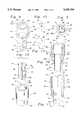
- FIG. 8is a perspective view of a polygonal drive adapter in accordance with the present invention.
- FIG. 9is a reduced, top plan view of the drive adapter of FIG. 8;
- FIG. 10is an enlarged view in vertical section taken along the line 10--10 in FIG. 9, and with the drive lug shown in elevation;
- FIG. 11is an enlarged view in vertical section taken along the line 11--11 in FIG. 9, with the drive lug shown in elevation;
- FIG. 12is an exploded perspective view of the drive adapter of FIG. 8;
- FIG. 13is a reduced, top plan view of the drive lug of the drive adapter of FIG. 12;
- FIG. 14is a front elevational view of the drive lug of FIG. 13.
- a prior tool combination or assembly 10comprising a socket 11 and a bit 15.
- the socket 11has a drive recess 12 which may be substantially square in transverse cross section for receiving a drive lug of an associated driving tool (not shown), such as a ratchet wrench.
- the drive recess 12may be provided with detent recesses 13 for receiving a detent ball of the associated drive lug to retain the socket 11 in place on the driving tool in a known manner.
- the socket 11is provided at its other end with a workpiece-engaging recess (not shown), which is typically polygonal in transverse cross section and is adapted to receive a correspondingly shaped bit in a known manner.
- the bit 15has a shank 16 which is shaped for mating engagement in the workpiece-engaging recess of the socket 11, both the shank and the recess being hexagonal in shape in the illustrated embodiment.
- the bit 15is provided at its distal end with an application tip 17 shaped and dimensioned for a particular application.
- the application tip 17may be a screwdriver bit, a hexagonal key, or any of a number of other types of male drive configurations adapted to be received in complementary female recesses in members to be driven.
- a roll pin 18extends diametrically through complementary aligned bores in the socket 11 and the bit shank 16, to fixedly secure the bit 15 in the socket 11.
- a set screwcould be used.
- any of a number of different bitsmay be thus mounted in the socket 11, each of these bits having the same size and shape shank 16, but having different sized and/or shaped application tips 17, so that a single socket can be used to drive a number of different bits.
- the socket 11is similar to a standard configuration except for the presence of a diametrical bore in a thickened sidewall to accommodate the roll pin 18 or set screw.
- the use of the roll pin or set screw to mount and demount the bit 15is a major inconvenience, to the point that users typically purchase a separate socket for each bit to obviate bit changing. It represents an extra part with all the attendant disadvantages in manufacturing, inventorying, storage and use.
- the roll pin or set screw 18may work free in use or the roll pin may break, allowing the bit 15 to fall out of the socket 11.
- a friction ring(not shown) may be used in lieu of the roll pin or set screw 18 to retain the bit 15 in the socket 11. This simplifies bit interchange but does not provide a very secure retention of the bit.
- FIG. 5there is illustrated a tool combination or assembly 20 constructed in accordance with and embodying the features of the present invention, and including a socket 30 and a bit 50.
- the socket 30is adapted for use with an associated driving tool 21 having a drive lug 25 provided with a detent ball 26, in the same manner as was described above in connection with the socket 11.
- the socket 30includes a generally cylindrical body 31 having a drive end 32 and a bit end 33.
- the socket body 31has a hole 35 extending axially therethrough from the drive end 32 to the bit end 33 thereof.
- the hole 35includes a drive portion 36 which extends axially inwardly from the drive end 32 and is substantially square in transverse cross section for receiving the square drive lug 25 of the associated driving tool 21.
- the driving portion 36may be provided with beveled or tapered guide surfaces 37 at the entry end thereof to facilitate insertion of the drive lug 25, and may also be provided with detent recesses 38 for receiving the detent ball 26 of the drive lug 25 to retain the socket 30 on the drive lug 25, all in a known manner.
- the drive portion 36communicates at its inner end with a circularly cylindrical retaining portion 40 having a diameter less than the width of the drive portion 36, so that the bottom wall of the drive portion 36 defines a shoulder 39 which surrounds the retaining portion 40 and faces the drive end 32 of the socket 30.
- the other end of the retaining portion 40is joined by a frustoconical shoulder 41 to a hexagonal bit portion 45, which extends to the bit end 33 of the socket 30.
- the bit portion 45has a width which is less than the diameter of the retaining portion 40, so that the shoulder 41 converges toward the bit end 33 and faces the drive end 32 of the socket 30. While the bit portion 45 is illustrated as having a hexagonal shape, it will be appreciated that it could have other polygonal shapes.
- the bit 50has an elongated shank 51, hexagonal in transverse cross section and dimensioned to be mateably received in the bit portion 45 of the socket hole 35 for driven engagement thereby, in a known manner.
- the shank 51is provided at one end thereof with an application tip 52 which has a transverse width less than or equal to that of the shank 51 so as to be freely receivable through the bit portion 45 of the socket hole 35, and is provided at least at its distal end with a desired application configuration.
- the application tip 52has a fluted configuration, but it will be appreciated that any desired configuration, such as a screwdriver blade of any desired configuration, a hexagonal key, or the like may be used.
- the shank 51is provided at its other end with an enlarged, circularly cylindrical head 55, which is joined to the shank 51 by a circumferential undercut or groove 56 which is generally part-circular in transverse cross section.
- the head 55has a circular end surface 57 and a circularly cylindrical side surface 58 which has a diameter slightly greater than the width of the shank 51 and is dimensioned to be mateably received in the retaining portion 40 of the socket hole 35.
- the bit 50is dropped into the socket hole 35 from the drive end 32 of the socket 30. More specifically, the application tip 52 of the bit 50 is inserted into the drive portion 36 of the socket hole 35 and allowed to drop therethrough until it reaches a use position illustrated in FIG. 5, wherein the bit head 55 seats against the shoulder 41, with the shank 51 extending through the bit portion 45 and beyond the bit end 33 of the socket 30.
- the head 55 of the bit 50is so dimensioned that the end surface 57 thereof is substantially coplanar with the shoulder 39 when the head 55 is seated on the shoulder 41.
- bit 60which is substantially similar to the bit 50, with like parts bearing the same reference numerals.
- the bit 60is not provided with an enlarged head.
- the shank 51has a hexagonal end surface 61 and is provided with one or more laterally outwardly projecting ears 65 (one shown) spaced axially from the end surface 61 a distance substantially equal to the axial extent of the retaining portion 40 of the socket hole 35. While one ear 65 is illustrated, preferably two are provided at diametrically opposed locations on the shank 51.
- the ears 65are preferably at corners of the hexagonal shape, as illustrated, but could be located on the flats.
- the bit 60is inserted in the socket hole 35 in the same manner as was described above with respect to the bit 50, until the ears 65 seat against the shoulder 41. It will be appreciated that the positioning of the ears 65 is such that, when thus seated, the end surface 61 of the bit 60 is substantially coplanar with the shoulder 39 of the socket hole 35.
- the bit shank 51has a length such that, when the bit 50 or 60 is seated in its use position in the socket 30, the shank 51 projects well beyond the bit end 33 of the socket 30.
- the retaining portion of the bit 50 or 60i.e., the inner end of the head 55 or the ears 65, are spaced from the adjacent end surface 57 or 61 of the bit 50 or 60 a distance substantially less than the distance they are spaced from the opposite end of the shank 51.
- the latter distanceis three to six times the former.
- FIGS. 8-14there is illustrated a drive adapter, generally designated by the numeral 70, constructed in accordance with and embodying the features of the present invention, and including a socket 80 and a drive lug 90.
- the drive adapteris designed to transfer torque between male and female drive elements of different sizes.
- the drive adapter 70is illustrated as being a square drive, but it will be appreciated that other polygonal shapes, such as hexagonal, could be used, if desired.
- the socket 70is adapted for use with an associated driving tool having a male drive lug 71 provided with a detent ball 72, in a known manner (see FIGS. 10 and 11).
- the socket 80includes a generally cylindrical body 81 having a relatively large-diameter drive end 82 and a relatively small-diameter drive end 83.
- the socket body 81has a hole 85 extending axially therethrough from the large drive end 82 to the small drive end 83.
- the hole 85includes a large drive portion 86 which extends axially inwardly from the large drive end 82 and is substantially square in transverse cross section for receiving the square drive lug 71 of the associated driving tool in mating engagement therewith.
- the large drive portion 86may be provided with beveled or tapered guide surfaces 86a at the entry end thereof to facilitate insertion of the drive lug 71.
- the large drive portion 86 of the hole 85communicates at its inner end with a small drive portion 87 having a substantially square transverse cross section of a smaller area than that of the large drive portion 86, so that the bottom wall of the large drive portion 86 defines a shoulder 88 which surrounds the small drive portion 87 and faces the large drive end 82 of the socket 80.
- Each of the drive portions 86 and 87is defined by four substantially planar side walls.
- the walls of the large drive portion 86may, respectively, be provided with detent recesses 89 for receiving the detent ball 72 of the drive lug 71, while the walls of the small drive portion 87 may, respectively, be provided with small detent recesses 89a for a purpose to be described below (see FIGS. 10 and 11).
- the drive lug 90is in the nature of an elongated bar substantially square in transverse cross section and dimensioned for mating engagement in the small drive portion 87 of the hole 85.
- the drive lug 90has substantially parallel, flat square end surfaces 91 and 92, respectively at the opposite ends thereof, and four flat, rectangular side surfaces 93 joined by four corners 94, each of which may be slightly beveled or rounded.
- Two opposed ones of the corners 94are upset crimped adjacent to the end surface 91 to define two laterally outwardly projecting retaining ears 95.
- Each of the retaining ears 95has a short axial extent and is preferably formed at the end surface 91, but could be spaced a slight distance therefrom.
- the retaining ears 95are preferably formed at the corners 94 for ease of manufacture, they could be formed along the side surfaces 93.
- One of the side surfaces 93is provided with axially spaced-apart recesses in which are respectively received spring-loaded detent balls 97 and 98, in a known manner.
- the drive lug 90is dropped into the socket hole 85 from the large drive end 82 thereof. More specifically, the end surface 92 of the drive lug 90 is inserted into the large drive portion 86 of the hole 85 and allowed to drop therethrough and through the small drive portion 87 until it reaches a use position illustrated in FIGS. 8-11, wherein the retaining ears 95 seat against the shoulder 88, with the drive lug 90 extending through the small drive portion 87 of the hole 85 and beyond the small drive end 83 of the socket 80.
- the detent ball 97is disposed in engagement in one of the detent recesses 89a for facilitating retention of the drive lug 90 in the socket hole 85, while the detent ball 98 is disposed outwardly beyond the small drive end 83 of the socket 80 a predetermined distance for engagement in an associated detent recess in an associated female drive element (not shown).
- the drive lug 71 of the associated driving toolis inserted in the large drive portion 86 of the hole 85, as illustrated in FIGS. 10 and 11, it retains the drive lug 90 in place in the hole 85 and cooperates with the shoulder 88 substantially to inhibit axial movement of the drive lug 90.
- the drive adapter 70affords significant advantages over prior one-piece drive adapters. Because the socket 80 and the drive lug 90 are discrete, separable members, they may be formed of different materials and/or may be provided with different heat treatments so that the smaller cross-section drive lug 90 may be of higher strength than the larger diameter socket to minimize the chance of breakage of the smaller cross-section drive lug 90 in use. Furthermore, in the event that the drive lug 90 does break, it can be separately replaced at significantly lower cost than the cost of replacing an entire one-piece drive adapter.
Landscapes
- Engineering & Computer Science (AREA)
- Mechanical Engineering (AREA)
- Details Of Spanners, Wrenches, And Screw Drivers And Accessories (AREA)
Abstract
Description
This is a continuation-in-part of U.S. application Ser. No. 036,321, filed Mar. 24, 1993, now U.S. Pat. No. 5,343,786.
1. Field of the Invention
The present invention relates to socket wrench sets and, in particular, to sockets adapted for use with any of a plurality of different-sized driven members. The invention has particular application to drive adapters for converting from one size of polygonal drive to another.
2. Description of the Prior Art
Socket wrench sets are typically provided with one or more square drive wrenches, each having a square drive lug adapted to be coupled to a variety of different-sized sockets. A typical wrench set may include a plurality of different wrenches with different-sized square drive lugs, each of which can mate with a plurality of different sockets. For the purpose of converting from one size of drive to another, drive adapters are provided. A drive adapter has a square drive socket at one end of a first size and a square drive lug at the other end of a second size, the socket being adapted for mating engagement with an associated male square drive element, as on a wrench tool, while the drive lug is adapted for mating engagement with an associated female element, such as an associated socket tool.
Such prior adapters are of one-piece construction and are characterized by a rather abrupt change in cross-section where the drive lug joins the remainder of the adapter body. The drive lug is subject to breakage from the socket at this transition when very high torque is applied. While it is possible to make the adapter of a material, or subject it to a heat treatment, to increase its strength so that it would resist breakage, this material or treatment would have to be applied to the entire adapter, even though it would not be necessary for the socket portion, thereby significantly increasing the cost of the adapter.
It is known to provide socket wrench sets wherein at least one of the sockets is a bit socket, i.e., a socket which is adapted to receive any of a number of different-sized bits. Such bits may be of any of a number of different types, such as screwdriver bits, wrench bits and other types of drive configurations. Typically, each such bit has a polygonal shank provided at an application end with a drive configuration adapted for a particular drive application. The shank is dimensioned to fit into the workpiece-engaging end of a wrenching socket, being retained in place therein by a set screw or roll pin or the like, received through radial bores in the socket, or by a friction ring, such as a wire ring or O-ring. For example, the socket may have a hexagonal workpiece engaging end, in which case each of the bits will have a hexagonal shaft mateably engageable in the socket. The socket also has a drive recess at a drive end thereof, which may be a square recess adapted to receive a drive lug of an associated driving tool, such as a ratchet wrench or the like. In this way, a single socket may be used with a driving tool to drive a plurality of different bits.
However, in this prior arrangement, in the event a set screw or roll pin is used for bit retention, engagement and disengagement of the bits in the socket is relatively cumbersome and time consuming, requiring the mounting and demounting of the set screw or roll pin, each time the bit is changed. Indeed, it is so cumbersome that normally a user will purchase a separate socket for each bit to obviate bit changing. Furthermore, the set screw or roll pin constitutes an additional part which must be manufactured, inventoried, and kept track of, which adds to the cost of manufacture and assembly, and further entails the risk of loss by the user. The use of a friction ring for bit retention simplifies bit changing but does not provide a very secure retention.
It is also known to provide a bit set for use with a box ratchet wrench, each of the bits having a shank which is insertable into the box ratchet, and the depth of insertion being limited by a lateral projection on the bit shank approximately midway along its length. Such ratchet and bit sets are sold, for example, by Snap-on Tools Corporation under the designation CRA180PB. Typically, the box ratchet is provided with an O-ring or the like to frictionally hold the bit in place in the ratchet.
It is a general object of the invention to provide an improved polygonal drive adapter which avoids the disadvantages of prior adapters while affording additional structural and operating advantages.
An important feature of the invention is the provision of a drive adapter which is of simple and economical construction, and yet which can be made of sufficient strength to resist breakage of the drive lug portion of the adapter from the socket portion.
In connection with the foregoing feature, a further feature of the invention is the provision of a drive adapter of the type set forth, which is of economical construction such as to reduce cost of replacement in the event of breakage.
A further feature of the invention is the provision of a drive adapter which is of two-part construction, including a socket portion separable from a drive lug portion.
In connection with the foregoing feature, a further feature of the invention is the provision of a drive adapter of the type set forth, which is characterized by economy of manufacture and ease of use.
These and other features of the invention are attained by providing a polygonal drive adapter for transmitting torque between polygonal male and female drive elements of different size comprising: a unitary one-piece socket member having first and second ends and a longitudinal hole therethrough from end-to-end, the hole having a first polygonal portion of a first size adjacent to the first end for receiving an associated male polygonal drive element in mating engagement therewith and a second polygonal portion of a second size different from the first size adjacent to the second end, a shoulder in the hole between the first and second portions facing the first end, and an elongated polygonal drive lug having an application end receivable in the second portion of the hole in mating engagement therewith and adapted for mating engagement with an associated female drive element and a coupling end, the drive lug having a plurality of flat planar sides joined by a plurality of corner portions, the drive lug including laterally extending retaining projections at spaced-apart locations adjacent to the coupling end, the application end of the drive lug being insertable in and removable from the hole from the first end thereof with the projections engageable with the shoulder to limit the depth of insertion at a working position wherein the application end of the drive lug projects outwardly beyond the second end of the socket member.
The invention consists of certain novel features and a combination of parts hereinafter fully described, illustrated in the accompanying drawings, and particularly pointed out in the appended claims, it being understood that various changes in the details may be made without departing from the spirit, or sacrificing any of the advantages of the present invention.
For the purpose of facilitating an understanding of the invention, there is illustrated in the accompanying drawings a preferred embodiment thereof, from an inspection of which, when considered in connection with the following description, the invention, its construction and operation, and many of its advantages should be readily understood and appreciated.
FIG. 1 is a perspective view of a prior art bit and socket combination;
FIG. 2 is a perspective view of a socket constructed in accordance with and embodying the features of the present invention;
FIG. 3 is a top plan view of the socket of FIG. 2;
FIG. 4 is an exploded view in vertical section of the socket of FIG. 2 and an associated bit in accordance with the present invention;
FIG. 5 is an enlarged view in vertical section of the socket of FIG. 4 with the bit of FIG. 4 engaged therein and illustrated in side elevation, and with an associated drive lug illustrated in phantom;
FIG. 6 is a perspective view of the bit of FIG. 4;
FIG. 7 is a view similar to FIG. 6 of a bit in accordance with another embodiment of the invention;
FIG. 8 is a perspective view of a polygonal drive adapter in accordance with the present invention;
FIG. 9 is a reduced, top plan view of the drive adapter of FIG. 8;
FIG. 10 is an enlarged view in vertical section taken along theline 10--10 in FIG. 9, and with the drive lug shown in elevation;
FIG. 11 is an enlarged view in vertical section taken along theline 11--11 in FIG. 9, with the drive lug shown in elevation;
FIG. 12 is an exploded perspective view of the drive adapter of FIG. 8;
FIG. 13 is a reduced, top plan view of the drive lug of the drive adapter of FIG. 12; and
FIG. 14 is a front elevational view of the drive lug of FIG. 13.
Referring to FIG. 1, there is illustrated a prior tool combination orassembly 10 comprising asocket 11 and abit 15. Thesocket 11 has adrive recess 12 which may be substantially square in transverse cross section for receiving a drive lug of an associated driving tool (not shown), such as a ratchet wrench. Thedrive recess 12 may be provided withdetent recesses 13 for receiving a detent ball of the associated drive lug to retain thesocket 11 in place on the driving tool in a known manner. Thesocket 11 is provided at its other end with a workpiece-engaging recess (not shown), which is typically polygonal in transverse cross section and is adapted to receive a correspondingly shaped bit in a known manner.
Thebit 15 has ashank 16 which is shaped for mating engagement in the workpiece-engaging recess of thesocket 11, both the shank and the recess being hexagonal in shape in the illustrated embodiment. Thebit 15 is provided at its distal end with anapplication tip 17 shaped and dimensioned for a particular application. For example, theapplication tip 17 may be a screwdriver bit, a hexagonal key, or any of a number of other types of male drive configurations adapted to be received in complementary female recesses in members to be driven. Aroll pin 18 extends diametrically through complementary aligned bores in thesocket 11 and thebit shank 16, to fixedly secure thebit 15 in thesocket 11. Alternatively, a set screw could be used.
It will be appreciated that any of a number of different bits may be thus mounted in thesocket 11, each of these bits having the same size and shapeshank 16, but having different sized and/or shapedapplication tips 17, so that a single socket can be used to drive a number of different bits. Thesocket 11 is similar to a standard configuration except for the presence of a diametrical bore in a thickened sidewall to accommodate theroll pin 18 or set screw. However, the use of the roll pin or set screw to mount and demount thebit 15 is a major inconvenience, to the point that users typically purchase a separate socket for each bit to obviate bit changing. It represents an extra part with all the attendant disadvantages in manufacturing, inventorying, storage and use. Furthermore, the roll pin or setscrew 18 may work free in use or the roll pin may break, allowing thebit 15 to fall out of thesocket 11. A friction ring (not shown) may be used in lieu of the roll pin or setscrew 18 to retain thebit 15 in thesocket 11. This simplifies bit interchange but does not provide a very secure retention of the bit.
Referring to FIG. 5, there is illustrated a tool combination orassembly 20 constructed in accordance with and embodying the features of the present invention, and including asocket 30 and abit 50. Thesocket 30 is adapted for use with an associateddriving tool 21 having adrive lug 25 provided with adetent ball 26, in the same manner as was described above in connection with thesocket 11.
Referring also to FIGS. 2-4, thesocket 30 includes a generallycylindrical body 31 having adrive end 32 and abit end 33. Thesocket body 31 has ahole 35 extending axially therethrough from thedrive end 32 to the bit end 33 thereof. Thehole 35 includes adrive portion 36 which extends axially inwardly from thedrive end 32 and is substantially square in transverse cross section for receiving thesquare drive lug 25 of the associated drivingtool 21. The drivingportion 36 may be provided with beveled or tapered guide surfaces 37 at the entry end thereof to facilitate insertion of thedrive lug 25, and may also be provided with detent recesses 38 for receiving thedetent ball 26 of thedrive lug 25 to retain thesocket 30 on thedrive lug 25, all in a known manner.
Thedrive portion 36 communicates at its inner end with a circularlycylindrical retaining portion 40 having a diameter less than the width of thedrive portion 36, so that the bottom wall of thedrive portion 36 defines ashoulder 39 which surrounds the retainingportion 40 and faces thedrive end 32 of thesocket 30. The other end of the retainingportion 40 is joined by afrustoconical shoulder 41 to ahexagonal bit portion 45, which extends to the bit end 33 of thesocket 30. Thebit portion 45 has a width which is less than the diameter of the retainingportion 40, so that theshoulder 41 converges toward the bit end 33 and faces thedrive end 32 of thesocket 30. While thebit portion 45 is illustrated as having a hexagonal shape, it will be appreciated that it could have other polygonal shapes.
Referring in particular to FIGS. 4, 5 and 6, thebit 50, has an elongatedshank 51, hexagonal in transverse cross section and dimensioned to be mateably received in thebit portion 45 of thesocket hole 35 for driven engagement thereby, in a known manner. Theshank 51 is provided at one end thereof with anapplication tip 52 which has a transverse width less than or equal to that of theshank 51 so as to be freely receivable through thebit portion 45 of thesocket hole 35, and is provided at least at its distal end with a desired application configuration. In the illustrated embodiment, theapplication tip 52 has a fluted configuration, but it will be appreciated that any desired configuration, such as a screwdriver blade of any desired configuration, a hexagonal key, or the like may be used. Theshank 51 is provided at its other end with an enlarged, circularlycylindrical head 55, which is joined to theshank 51 by a circumferential undercut or groove 56 which is generally part-circular in transverse cross section. Thehead 55 has acircular end surface 57 and a circularlycylindrical side surface 58 which has a diameter slightly greater than the width of theshank 51 and is dimensioned to be mateably received in the retainingportion 40 of thesocket hole 35.
In operation, thebit 50 is dropped into thesocket hole 35 from thedrive end 32 of thesocket 30. More specifically, theapplication tip 52 of thebit 50 is inserted into thedrive portion 36 of thesocket hole 35 and allowed to drop therethrough until it reaches a use position illustrated in FIG. 5, wherein the bit head 55 seats against theshoulder 41, with theshank 51 extending through thebit portion 45 and beyond the bit end 33 of thesocket 30. Preferably, thehead 55 of thebit 50 is so dimensioned that theend surface 57 thereof is substantially coplanar with theshoulder 39 when thehead 55 is seated on theshoulder 41. It will be appreciated that when thedrive lug 25 of the drivingtool 21 is inserted in thedrive portion 36 of thesocket hole 35, it retains thebit 50 in place in thehole 35 and cooperates with theshoulder 41 substantially to inhibit axial movement of thebit 50. Thus, separate retaining members, such as roll pins or set screws are obviated.
Referring to FIG. 7, there is illustrated an alternative form ofbit 60, which is substantially similar to thebit 50, with like parts bearing the same reference numerals. However, thebit 60 is not provided with an enlarged head. Rather, theshank 51 has ahexagonal end surface 61 and is provided with one or more laterally outwardly projecting ears 65 (one shown) spaced axially from the end surface 61 a distance substantially equal to the axial extent of the retainingportion 40 of thesocket hole 35. While oneear 65 is illustrated, preferably two are provided at diametrically opposed locations on theshank 51. Theears 65 are preferably at corners of the hexagonal shape, as illustrated, but could be located on the flats. Thus, it will be appreciated that thebit 60 is inserted in thesocket hole 35 in the same manner as was described above with respect to thebit 50, until theears 65 seat against theshoulder 41. It will be appreciated that the positioning of theears 65 is such that, when thus seated, theend surface 61 of thebit 60 is substantially coplanar with theshoulder 39 of thesocket hole 35.
Preferably, thebit shank 51 has a length such that, when thebit socket 30, theshank 51 projects well beyond the bit end 33 of thesocket 30. In any event, the retaining portion of thebit head 55 or theears 65, are spaced from theadjacent end surface bit 50 or 60 a distance substantially less than the distance they are spaced from the opposite end of theshank 51. Preferably, the latter distance is three to six times the former.
Referring now to FIGS. 8-14, there is illustrated a drive adapter, generally designated by the numeral 70, constructed in accordance with and embodying the features of the present invention, and including asocket 80 and adrive lug 90. The drive adapter is designed to transfer torque between male and female drive elements of different sizes. Thedrive adapter 70 is illustrated as being a square drive, but it will be appreciated that other polygonal shapes, such as hexagonal, could be used, if desired. Thesocket 70 is adapted for use with an associated driving tool having amale drive lug 71 provided with adetent ball 72, in a known manner (see FIGS. 10 and 11).
Thesocket 80 includes a generallycylindrical body 81 having a relatively large-diameter drive end 82 and a relatively small-diameter drive end 83. Thesocket body 81 has ahole 85 extending axially therethrough from thelarge drive end 82 to thesmall drive end 83. Thehole 85 includes alarge drive portion 86 which extends axially inwardly from thelarge drive end 82 and is substantially square in transverse cross section for receiving thesquare drive lug 71 of the associated driving tool in mating engagement therewith. Thelarge drive portion 86 may be provided with beveled or taperedguide surfaces 86a at the entry end thereof to facilitate insertion of thedrive lug 71. Thelarge drive portion 86 of thehole 85 communicates at its inner end with asmall drive portion 87 having a substantially square transverse cross section of a smaller area than that of thelarge drive portion 86, so that the bottom wall of thelarge drive portion 86 defines ashoulder 88 which surrounds thesmall drive portion 87 and faces thelarge drive end 82 of thesocket 80. Each of thedrive portions large drive portion 86 may, respectively, be provided with detent recesses 89 for receiving thedetent ball 72 of thedrive lug 71, while the walls of thesmall drive portion 87 may, respectively, be provided withsmall detent recesses 89a for a purpose to be described below (see FIGS. 10 and 11).
Thedrive lug 90 is in the nature of an elongated bar substantially square in transverse cross section and dimensioned for mating engagement in thesmall drive portion 87 of thehole 85. Thedrive lug 90 has substantially parallel, flat square end surfaces 91 and 92, respectively at the opposite ends thereof, and four flat, rectangular side surfaces 93 joined by fourcorners 94, each of which may be slightly beveled or rounded. Two opposed ones of thecorners 94 are upset crimped adjacent to theend surface 91 to define two laterally outwardly projecting retainingears 95. Each of the retainingears 95 has a short axial extent and is preferably formed at theend surface 91, but could be spaced a slight distance therefrom. Also, while the retainingears 95 are preferably formed at thecorners 94 for ease of manufacture, they could be formed along the side surfaces 93. One of the side surfaces 93 is provided with axially spaced-apart recesses in which are respectively received spring-loadeddetent balls
In operation, thedrive lug 90 is dropped into thesocket hole 85 from thelarge drive end 82 thereof. More specifically, theend surface 92 of thedrive lug 90 is inserted into thelarge drive portion 86 of thehole 85 and allowed to drop therethrough and through thesmall drive portion 87 until it reaches a use position illustrated in FIGS. 8-11, wherein the retainingears 95 seat against theshoulder 88, with thedrive lug 90 extending through thesmall drive portion 87 of thehole 85 and beyond thesmall drive end 83 of thesocket 80. In this use position, thedetent ball 97 is disposed in engagement in one of the detent recesses 89a for facilitating retention of thedrive lug 90 in thesocket hole 85, while thedetent ball 98 is disposed outwardly beyond thesmall drive end 83 of the socket 80 a predetermined distance for engagement in an associated detent recess in an associated female drive element (not shown). It will be appreciated that when thedrive lug 71 of the associated driving tool is inserted in thelarge drive portion 86 of thehole 85, as illustrated in FIGS. 10 and 11, it retains thedrive lug 90 in place in thehole 85 and cooperates with theshoulder 88 substantially to inhibit axial movement of thedrive lug 90.
It will be appreciated that thedrive adapter 70 affords significant advantages over prior one-piece drive adapters. Because thesocket 80 and thedrive lug 90 are discrete, separable members, they may be formed of different materials and/or may be provided with different heat treatments so that the smallercross-section drive lug 90 may be of higher strength than the larger diameter socket to minimize the chance of breakage of the smallercross-section drive lug 90 in use. Furthermore, in the event that thedrive lug 90 does break, it can be separately replaced at significantly lower cost than the cost of replacing an entire one-piece drive adapter.
From the foregoing, it can be seen that there have been provided improved combination tools which are of simple and economical construction and characterized by ease of use with a minimum number of parts. In particular, there has been provided an improved drive adapter of two-part construction so that the lug portion of the adapter is separable from the socket portion thereof to minimize incidence of breakage and reduce replacement costs in the event of breakage.
Claims (12)
1. A polygonal drive adapter for transmitting torque between polygonal male and female drive elements of different size comprising: a unitary one-piece socket member having first and second ends and a longitudinal hole therethrough from end-to-end, said hole having a first polygonal portion of a first size adjacent to said first end for receiving an associated male polygonal drive element in mating engagement therewith and a second polygonal portion adjacent to said second end having the same cross-sectional shape as said first portion but of a second size different from said first size, a shoulder in said hole between said first and second portions facing said first end, and an elongated polygonal drive lug having an application end receivable in said second portion of said hole in mating engagement therewith and adapted for mating engagement with an associated female drive element and a coupling end, said drive lug having a plurality of flat planar sides joined by a plurality of corner portions, said drive lug including laterally extending retaining projections respectively formed at spaced-apart corner portions of said drive lug adjacent to said coupling end, said application end of said drive lug being insertable in and removable from said hole from said first end thereof with said projections engageable with said shoulder to limit the depth of insertion at a working position wherein said application end of said drive lug projects outwardly beyond said second end of said socket member.
2. The drive adapter of claim 1, wherein each of said first and second portions of said hole is substantially square in transverse cross section.
3. The drive adapter of claim 1, wherein said first portion of said hole is larger than said second portion thereof.
4. The drive adapter of claim 1, wherein said second portion of said hole and said drive lug are substantially square in transverse cross section.
5. The drive adapter of claim 4, wherein said projections are respectively disposed at opposed corner portions of said drive lug.
6. The drive adapter of claim 1, wherein each of said projections comprises a crimped corner portion of said drive lug.
7. The drive adapter of claim 6, wherein said crimped corner portions are disposed at said coupling end of said drive lug.
8. The drive adapter of claim 1, wherein said socket member includes a plurality of flat wall portions cooperating to define said first portion of said hole, at least one of said flat wall portions having a first detent recess formed therein.
9. The drive adapter of claim 8, wherein said body includes a plurality of second flat wall portions cooperating to define said second portion of said hole, at least one of said second wall portions having a second detent recess formed therein.
10. The drive adapter of claim 9, wherein said drive lug includes two detent balls at longitudinally spaced-apart locations thereon, one of said detent balls being disposed for engagement in said second detent recess to assist in retaining said drive lug in said hole.
11. The drive adapter of claim 1, wherein said drive lug includes a detent ball projecting laterally therefrom to facilitate engagement with the associated female drive element.
12. The drive adapter of claim 1, wherein said projections comprise upset crimped corner portions of said drive lug.
Priority Applications (1)
| Application Number | Priority Date | Filing Date | Title |
|---|---|---|---|
| US08/285,093US5485769A (en) | 1993-03-24 | 1994-08-03 | Square drive adapter |
Applications Claiming Priority (2)
| Application Number | Priority Date | Filing Date | Title |
|---|---|---|---|
| US08/036,321US5343786A (en) | 1993-03-24 | 1993-03-24 | Bit and socket combination |
| US08/285,093US5485769A (en) | 1993-03-24 | 1994-08-03 | Square drive adapter |
Related Parent Applications (1)
| Application Number | Title | Priority Date | Filing Date |
|---|---|---|---|
| US08/036,321Continuation-In-PartUS5343786A (en) | 1993-03-24 | 1993-03-24 | Bit and socket combination |
Publications (1)
| Publication Number | Publication Date |
|---|---|
| US5485769Atrue US5485769A (en) | 1996-01-23 |
Family
ID=46249187
Family Applications (1)
| Application Number | Title | Priority Date | Filing Date |
|---|---|---|---|
| US08/285,093Expired - LifetimeUS5485769A (en) | 1993-03-24 | 1994-08-03 | Square drive adapter |
Country Status (1)
| Country | Link |
|---|---|
| US (1) | US5485769A (en) |
Cited By (57)
| Publication number | Priority date | Publication date | Assignee | Title |
|---|---|---|---|---|
| USD379420S (en)* | 1996-03-11 | 1997-05-27 | Joan Standlee | Wing nut driver |
| DE19629352A1 (en)* | 1996-07-20 | 1998-01-22 | Anton Gaupp | Adaptor with two=ended female connector for use with ratchet fastener drive |
| US5752418A (en)* | 1997-01-03 | 1998-05-19 | T & L Robins Co., Inc. | Dual size socket drive adapter |
| US5860338A (en)* | 1997-04-07 | 1999-01-19 | Littlefield; Kirk A. | Dual drive adapter |
| US5960681A (en)* | 1996-07-31 | 1999-10-05 | Anderson; Wayne | Socket driver with retaining protuberances and method of manufacturing same |
| US6019019A (en)* | 1998-04-09 | 2000-02-01 | Specialty Auto Parts Usa, Inc. | Clearance extension for wrenches |
| US6085619A (en)* | 1998-08-13 | 2000-07-11 | Worktools, Inc. | Tool bit adapter for universal socket tool |
| US6244142B1 (en) | 1999-11-05 | 2001-06-12 | Richard C. Swanson | Truck king pin cap tool kit |
| EP1000709A3 (en)* | 1998-11-13 | 2002-05-22 | Illinois Tool Works Inc. | Fastener-driving accessory for rotary driving tool |
| US6427564B1 (en) | 2001-02-16 | 2002-08-06 | Willie J. Nelson | Socket hand grip device |
| US20020174749A1 (en)* | 2001-05-24 | 2002-11-28 | Clemons Robert W. | Drywall tool having a screwdriver adapter |
| US20050092140A1 (en)* | 2003-10-31 | 2005-05-05 | Spx Corporation | Apparatus and method for removing a bolt from an assembly |
| US20050204875A1 (en)* | 2004-03-19 | 2005-09-22 | Robert Schluter | Anti-tamper fastener |
| US20050278926A1 (en)* | 2004-06-16 | 2005-12-22 | Moore Daniel L | Baluster driver tool and method of using same |
| USD513162S1 (en)* | 2004-03-19 | 2005-12-27 | Robert Schluter | Driver bit |
| US20050284269A1 (en)* | 2004-06-23 | 2005-12-29 | Kun-Chih Hung | Auxiliary connector of ratchet wrench |
| US20060048609A1 (en)* | 2004-09-09 | 2006-03-09 | Leo Shih | Ratchet wrench adapted to operate with a different wrench |
| USD517404S1 (en) | 2004-03-19 | 2006-03-21 | Robert Schluter | Anti-tamper fastener |
| US20060100024A1 (en)* | 2004-11-05 | 2006-05-11 | Ming-Ta Cheng | Transmission shaft for a hand tool or a power tool |
| US20060118316A1 (en)* | 2004-12-02 | 2006-06-08 | One World Technologies Limited | Stepped shaft |
| US20060175773A1 (en)* | 2004-12-09 | 2006-08-10 | Mobiletron Electronics Co., Ltd. | Adapter for impact rotary tool |
| USD526547S1 (en)* | 2005-04-23 | 2006-08-15 | F. Kent Houpe | Pro lineman's socket |
| US20060196323A1 (en)* | 2005-03-03 | 2006-09-07 | Geary Ronald J | Compact auxiliary positioning driver for wrench |
| US20070163405A1 (en)* | 2006-01-17 | 2007-07-19 | Chin-Ching Hsieh | Multi-functional hand tool |
| US20070289416A1 (en)* | 2005-08-31 | 2007-12-20 | Chih-Ching Hsieh | Head replaceable tool |
| US20080127425A1 (en)* | 2006-12-01 | 2008-06-05 | Hsine-Jui Chen | Multi-functional tool |
| US20100260537A1 (en)* | 2009-04-09 | 2010-10-14 | Hong Fu Jin Precision Industry (Shenzhen) Co., Ltd | Connecting structure for swivel shafts |
| US7849767B1 (en)* | 2005-01-11 | 2010-12-14 | Wessel Iv Homer A | Connectors for a wrench assembly |
| US20110056714A1 (en)* | 2008-05-07 | 2011-03-10 | Milwaukee Electric Tool Corporation | Anvil assembly for a power tool |
| CN102975166A (en)* | 2012-11-30 | 2013-03-20 | 新昌电力公司 | Intra-Hexagonal tool |
| US20130272786A1 (en)* | 2011-12-02 | 2013-10-17 | David Ivinson | Stress reducing tool mount |
| CN103374770A (en)* | 2012-04-28 | 2013-10-30 | 欧瑞康纺织有限及两合公司 | Open-end spinning rotor |
| US8695461B2 (en) | 2010-12-22 | 2014-04-15 | Black & Decker Inc. | Cleanable magnetic nut driver |
| US20140196581A1 (en)* | 2013-01-17 | 2014-07-17 | Hong Ann Tool Industries Co., Ltd. | Reinforced Drive Tool |
| US20140260826A1 (en)* | 2013-03-14 | 2014-09-18 | Snap-On Incorporated | Socket and Bit Retention |
| US9156146B1 (en)* | 2014-01-22 | 2015-10-13 | Keith Maceo | Wrench adapter device |
| US20170239790A1 (en)* | 2016-02-22 | 2017-08-24 | Malco Products, Inc. | Cleanable reversible socket and driver |
| US20180043520A1 (en)* | 2016-08-11 | 2018-02-15 | Ronald Aho | Hammer drill adaptors and methods of use |
| US20190022834A1 (en)* | 2017-07-21 | 2019-01-24 | Snap-On Incorporated | Tool head with groove for removal from lug |
| USD853808S1 (en)* | 2017-05-16 | 2019-07-16 | Milwaukee Electric Tool Corporation | Driver |
| US20200198102A1 (en)* | 2018-12-20 | 2020-06-25 | Panda Tool Co., Ltd. | Socket Tool |
| USD900893S1 (en) | 2016-03-15 | 2020-11-03 | Brad A. English | Jagged tooth head fastener removal device for dirty environments |
| WO2020245000A1 (en)* | 2019-06-06 | 2020-12-10 | Wto Vermögensverwaltung Gmbh | Operating key for stationary and driven tool holders |
| US20210046624A1 (en)* | 2019-08-14 | 2021-02-18 | Kabo Tool Company | Hand tool for enhancing strength of working head |
| US10953521B2 (en) | 2017-05-16 | 2021-03-23 | Milwaukee Electric Tool Corporation | Driver |
| US11027400B2 (en)* | 2017-05-02 | 2021-06-08 | Apex Brands, Inc. | Electrically isolated coupling |
| US11318590B2 (en)* | 2019-07-17 | 2022-05-03 | Snap-On Incorporated | Tool extension |
| US20220143790A1 (en)* | 2020-11-12 | 2022-05-12 | Snap-On Incorporated | Universal joint tool adapter assembly |
| US20220168873A1 (en)* | 2020-11-30 | 2022-06-02 | Ming-Chang Chen | Non-magnetic locking sleeve |
| US11351664B2 (en) | 2019-04-04 | 2022-06-07 | Apex Brands, Inc. | Electrically isolated tool with non-conductive torque transfer component |
| US11389931B2 (en) | 2015-12-18 | 2022-07-19 | Apex Brands, Inc | Electrically isolated fastener driving device |
| US11565383B2 (en) | 2018-06-26 | 2023-01-31 | Apex Brands, Inc. | Electrically isolated adapter |
| USD1000236S1 (en) | 2021-01-11 | 2023-10-03 | Diversitech Corporation | Driver for reversible socket |
| US11772241B2 (en) | 2019-04-03 | 2023-10-03 | Apex Brands, Inc. | Electrically isolated tool with failsafe coating |
| USD1031399S1 (en) | 2021-07-09 | 2024-06-18 | Milwaukee Electric Tool Corporation | Socket holder |
| USD1036953S1 (en)* | 2021-06-03 | 2024-07-30 | Milwaukee Electric Tool Corporation | Socket tool |
| US12064864B2 (en) | 2021-07-09 | 2024-08-20 | Milwaukee Electric Tool Corporation | Socket holder |
Citations (7)
| Publication number | Priority date | Publication date | Assignee | Title |
|---|---|---|---|---|
| US2288584A (en)* | 1940-05-23 | 1942-06-30 | Harry Herschel Leiter | Surgeon's screw driver, screw holder, and stabilizer |
| US2519559A (en)* | 1946-02-04 | 1950-08-22 | Lee R Foster | Kit with slidably mounted tools |
| US4367663A (en)* | 1981-03-30 | 1983-01-11 | Merics Joseph S | Variable length torque rod |
| US4399723A (en)* | 1979-07-11 | 1983-08-23 | Gilles Marleau | Compact combination tool set |
| US4754670A (en)* | 1984-12-20 | 1988-07-05 | Raymond Walter E | Adjustable extension torque bar |
| US4982632A (en)* | 1986-05-12 | 1991-01-08 | Barmore Thomas C | Socket wrench set |
| US5168782A (en)* | 1991-04-01 | 1992-12-08 | Cromwell Robert W | Tool extension adapter for a tool drive |
- 1994
- 1994-08-03USUS08/285,093patent/US5485769A/ennot_activeExpired - Lifetime
Patent Citations (7)
| Publication number | Priority date | Publication date | Assignee | Title |
|---|---|---|---|---|
| US2288584A (en)* | 1940-05-23 | 1942-06-30 | Harry Herschel Leiter | Surgeon's screw driver, screw holder, and stabilizer |
| US2519559A (en)* | 1946-02-04 | 1950-08-22 | Lee R Foster | Kit with slidably mounted tools |
| US4399723A (en)* | 1979-07-11 | 1983-08-23 | Gilles Marleau | Compact combination tool set |
| US4367663A (en)* | 1981-03-30 | 1983-01-11 | Merics Joseph S | Variable length torque rod |
| US4754670A (en)* | 1984-12-20 | 1988-07-05 | Raymond Walter E | Adjustable extension torque bar |
| US4982632A (en)* | 1986-05-12 | 1991-01-08 | Barmore Thomas C | Socket wrench set |
| US5168782A (en)* | 1991-04-01 | 1992-12-08 | Cromwell Robert W | Tool extension adapter for a tool drive |
Non-Patent Citations (2)
| Title |
|---|
| Snap on Tools 1992 Catalog, p. 179, Ratchet and Bit Set.* |
| Snap-on Tools 1992 Catalog, p. 179, Ratchet and Bit Set. |
Cited By (90)
| Publication number | Priority date | Publication date | Assignee | Title |
|---|---|---|---|---|
| USD379420S (en)* | 1996-03-11 | 1997-05-27 | Joan Standlee | Wing nut driver |
| DE19629352A1 (en)* | 1996-07-20 | 1998-01-22 | Anton Gaupp | Adaptor with two=ended female connector for use with ratchet fastener drive |
| US5960681A (en)* | 1996-07-31 | 1999-10-05 | Anderson; Wayne | Socket driver with retaining protuberances and method of manufacturing same |
| US5752418A (en)* | 1997-01-03 | 1998-05-19 | T & L Robins Co., Inc. | Dual size socket drive adapter |
| US5860338A (en)* | 1997-04-07 | 1999-01-19 | Littlefield; Kirk A. | Dual drive adapter |
| US6019019A (en)* | 1998-04-09 | 2000-02-01 | Specialty Auto Parts Usa, Inc. | Clearance extension for wrenches |
| US6085619A (en)* | 1998-08-13 | 2000-07-11 | Worktools, Inc. | Tool bit adapter for universal socket tool |
| EP1000709A3 (en)* | 1998-11-13 | 2002-05-22 | Illinois Tool Works Inc. | Fastener-driving accessory for rotary driving tool |
| US6244142B1 (en) | 1999-11-05 | 2001-06-12 | Richard C. Swanson | Truck king pin cap tool kit |
| US6427564B1 (en) | 2001-02-16 | 2002-08-06 | Willie J. Nelson | Socket hand grip device |
| US20020174749A1 (en)* | 2001-05-24 | 2002-11-28 | Clemons Robert W. | Drywall tool having a screwdriver adapter |
| US20050092140A1 (en)* | 2003-10-31 | 2005-05-05 | Spx Corporation | Apparatus and method for removing a bolt from an assembly |
| US7077037B2 (en)* | 2003-10-31 | 2006-07-18 | Spx Corporation | Apparatus and method for removing a bolt from an assembly |
| USD524637S1 (en) | 2004-03-19 | 2006-07-11 | Robert Schluter | Anti-tamper fastener |
| US20050204875A1 (en)* | 2004-03-19 | 2005-09-22 | Robert Schluter | Anti-tamper fastener |
| USD546655S1 (en) | 2004-03-19 | 2007-07-17 | Middle Atlantic Products, Inc. | Driver bit |
| USD528395S1 (en) | 2004-03-19 | 2006-09-19 | Robert Schluter | Driver bit |
| USD517404S1 (en) | 2004-03-19 | 2006-03-21 | Robert Schluter | Anti-tamper fastener |
| USD513162S1 (en)* | 2004-03-19 | 2005-12-27 | Robert Schluter | Driver bit |
| USD546157S1 (en) | 2004-03-19 | 2007-07-10 | Middle Atlantic Products, Inc. | Driver bit |
| US20050278926A1 (en)* | 2004-06-16 | 2005-12-22 | Moore Daniel L | Baluster driver tool and method of using same |
| US20080028893A1 (en)* | 2004-06-16 | 2008-02-07 | L.J. Smith, Inc. | Baluster driver tool and method of using the same |
| US7281310B2 (en)* | 2004-06-16 | 2007-10-16 | L.J. Smith, Inc. | Baluster driver tool and method of using same |
| US20050284269A1 (en)* | 2004-06-23 | 2005-12-29 | Kun-Chih Hung | Auxiliary connector of ratchet wrench |
| US20060048609A1 (en)* | 2004-09-09 | 2006-03-09 | Leo Shih | Ratchet wrench adapted to operate with a different wrench |
| US20060100024A1 (en)* | 2004-11-05 | 2006-05-11 | Ming-Ta Cheng | Transmission shaft for a hand tool or a power tool |
| US20060118316A1 (en)* | 2004-12-02 | 2006-06-08 | One World Technologies Limited | Stepped shaft |
| US7207393B2 (en)* | 2004-12-02 | 2007-04-24 | Eastway Fair Company Ltd. | Stepped drive shaft for a power tool |
| US20060175773A1 (en)* | 2004-12-09 | 2006-08-10 | Mobiletron Electronics Co., Ltd. | Adapter for impact rotary tool |
| US7849767B1 (en)* | 2005-01-11 | 2010-12-14 | Wessel Iv Homer A | Connectors for a wrench assembly |
| US7143670B2 (en)* | 2005-03-03 | 2006-12-05 | Kennametal Inc. | Compact auxiliary positioning driver for wrench |
| US20060196323A1 (en)* | 2005-03-03 | 2006-09-07 | Geary Ronald J | Compact auxiliary positioning driver for wrench |
| USD526547S1 (en)* | 2005-04-23 | 2006-08-15 | F. Kent Houpe | Pro lineman's socket |
| US20070289416A1 (en)* | 2005-08-31 | 2007-12-20 | Chih-Ching Hsieh | Head replaceable tool |
| US7340984B2 (en)* | 2006-01-17 | 2008-03-11 | Chih-Ching Hsieh | Multi-functional hand tool |
| US20070163405A1 (en)* | 2006-01-17 | 2007-07-19 | Chin-Ching Hsieh | Multi-functional hand tool |
| US20080127425A1 (en)* | 2006-12-01 | 2008-06-05 | Hsine-Jui Chen | Multi-functional tool |
| US20110056714A1 (en)* | 2008-05-07 | 2011-03-10 | Milwaukee Electric Tool Corporation | Anvil assembly for a power tool |
| US8839879B2 (en)* | 2008-05-07 | 2014-09-23 | Milwaukee Electric Tool Corporation | Anvil assembly for a power tool |
| US20100260537A1 (en)* | 2009-04-09 | 2010-10-14 | Hong Fu Jin Precision Industry (Shenzhen) Co., Ltd | Connecting structure for swivel shafts |
| US8695461B2 (en) | 2010-12-22 | 2014-04-15 | Black & Decker Inc. | Cleanable magnetic nut driver |
| US8783997B2 (en)* | 2011-12-02 | 2014-07-22 | Eca Medical Instruments | Stress reducing tool mount |
| US20130272786A1 (en)* | 2011-12-02 | 2013-10-17 | David Ivinson | Stress reducing tool mount |
| US8943667B2 (en) | 2011-12-02 | 2015-02-03 | Eca Medical Instruments | Stress reducing tool mounting method |
| CN103374770A (en)* | 2012-04-28 | 2013-10-30 | 欧瑞康纺织有限及两合公司 | Open-end spinning rotor |
| US20130283754A1 (en)* | 2012-04-28 | 2013-10-31 | Oerlikon Textile Gmbh & Co., Kg. | Open-end spinning rotor |
| US8875482B2 (en)* | 2012-04-28 | 2014-11-04 | Saurer Germany Gmbh & Co. Kg | Open-end spinning rotor |
| CN102975166A (en)* | 2012-11-30 | 2013-03-20 | 新昌电力公司 | Intra-Hexagonal tool |
| US9827654B2 (en) | 2013-01-17 | 2017-11-28 | Hong Ann Tool Industries Co., Ltd. | Reinforced drive tool |
| US20140196581A1 (en)* | 2013-01-17 | 2014-07-17 | Hong Ann Tool Industries Co., Ltd. | Reinforced Drive Tool |
| US9144893B2 (en)* | 2013-01-17 | 2015-09-29 | Hong Ann Tool Industries Co., Ltd. | Reinforced drive tool |
| US20140260826A1 (en)* | 2013-03-14 | 2014-09-18 | Snap-On Incorporated | Socket and Bit Retention |
| US10759027B2 (en)* | 2013-03-14 | 2020-09-01 | Snap-On Incorporated | Socket and bit retention |
| US9156146B1 (en)* | 2014-01-22 | 2015-10-13 | Keith Maceo | Wrench adapter device |
| US11865675B2 (en) | 2015-12-18 | 2024-01-09 | Apex Brands, Inc. | Electrically isolated fastener driving device |
| US11389931B2 (en) | 2015-12-18 | 2022-07-19 | Apex Brands, Inc | Electrically isolated fastener driving device |
| US20170239790A1 (en)* | 2016-02-22 | 2017-08-24 | Malco Products, Inc. | Cleanable reversible socket and driver |
| US9981366B2 (en)* | 2016-02-22 | 2018-05-29 | Malco Products, Inc. | Cleanable reversible socket and driver |
| USD900893S1 (en) | 2016-03-15 | 2020-11-03 | Brad A. English | Jagged tooth head fastener removal device for dirty environments |
| US20180043520A1 (en)* | 2016-08-11 | 2018-02-15 | Ronald Aho | Hammer drill adaptors and methods of use |
| US10589410B2 (en)* | 2016-08-11 | 2020-03-17 | Ronald Aho | Hammer drill adaptors and methods of use |
| US11027400B2 (en)* | 2017-05-02 | 2021-06-08 | Apex Brands, Inc. | Electrically isolated coupling |
| USD853808S1 (en)* | 2017-05-16 | 2019-07-16 | Milwaukee Electric Tool Corporation | Driver |
| US10953521B2 (en) | 2017-05-16 | 2021-03-23 | Milwaukee Electric Tool Corporation | Driver |
| USD896047S1 (en) | 2017-05-16 | 2020-09-15 | Milwaukee Electric Tool Corporation | Driver |
| US11541518B2 (en)* | 2017-07-21 | 2023-01-03 | Snap-On Incorporated | Tool head with groove for removal from lug |
| US20190022834A1 (en)* | 2017-07-21 | 2019-01-24 | Snap-On Incorporated | Tool head with groove for removal from lug |
| US11565383B2 (en) | 2018-06-26 | 2023-01-31 | Apex Brands, Inc. | Electrically isolated adapter |
| US20200198102A1 (en)* | 2018-12-20 | 2020-06-25 | Panda Tool Co., Ltd. | Socket Tool |
| US11084149B2 (en)* | 2018-12-20 | 2021-08-10 | Panda Tool Co., Ltd. | Socket tool |
| US11772241B2 (en) | 2019-04-03 | 2023-10-03 | Apex Brands, Inc. | Electrically isolated tool with failsafe coating |
| US11772248B2 (en) | 2019-04-04 | 2023-10-03 | Apex Brands, Inc. | Electrically isolated tool with non-conductive torque transfer component |
| US11351664B2 (en) | 2019-04-04 | 2022-06-07 | Apex Brands, Inc. | Electrically isolated tool with non-conductive torque transfer component |
| CN113825594A (en)* | 2019-06-06 | 2021-12-21 | Wto资产管理有限公司 | Operating key for stationary and driven tool holders |
| US12325076B2 (en) | 2019-06-06 | 2025-06-10 | Wto Vermögensverwaltung Gmbh | Operating key for stationary and driven tool holders |
| WO2020245000A1 (en)* | 2019-06-06 | 2020-12-10 | Wto Vermögensverwaltung Gmbh | Operating key for stationary and driven tool holders |
| US11318590B2 (en)* | 2019-07-17 | 2022-05-03 | Snap-On Incorporated | Tool extension |
| US20210046624A1 (en)* | 2019-08-14 | 2021-02-18 | Kabo Tool Company | Hand tool for enhancing strength of working head |
| US12103145B2 (en)* | 2019-08-14 | 2024-10-01 | Kabo Tool Company | Hand tool for enhancing strength of working head |
| CN114473941B (en)* | 2020-11-12 | 2025-03-28 | 施耐宝公司 | Universal Joint Tool Adapter Kit |
| CN114473941A (en)* | 2020-11-12 | 2022-05-13 | 施耐宝公司 | Universal joint tool adapter assembly |
| US20220143790A1 (en)* | 2020-11-12 | 2022-05-12 | Snap-On Incorporated | Universal joint tool adapter assembly |
| US12390911B2 (en)* | 2020-11-12 | 2025-08-19 | Snap-On Incorporated | Universal joint tool adapter assembly |
| US20220168873A1 (en)* | 2020-11-30 | 2022-06-02 | Ming-Chang Chen | Non-magnetic locking sleeve |
| US11685027B2 (en)* | 2020-11-30 | 2023-06-27 | Ming-Chang Chen | Non-magneiic locking sleeve |
| USD1000236S1 (en) | 2021-01-11 | 2023-10-03 | Diversitech Corporation | Driver for reversible socket |
| USD1036953S1 (en)* | 2021-06-03 | 2024-07-30 | Milwaukee Electric Tool Corporation | Socket tool |
| USD1063580S1 (en) | 2021-07-09 | 2025-02-25 | Milwaukee Electric Tool Corporation | Socket holder |
| US12064864B2 (en) | 2021-07-09 | 2024-08-20 | Milwaukee Electric Tool Corporation | Socket holder |
| USD1031399S1 (en) | 2021-07-09 | 2024-06-18 | Milwaukee Electric Tool Corporation | Socket holder |
Similar Documents
| Publication | Publication Date | Title |
|---|---|---|
| US5485769A (en) | Square drive adapter | |
| US4882958A (en) | Stacking socket wrench set | |
| US5343786A (en) | Bit and socket combination | |
| US7036401B2 (en) | Extendable spline-drive socket system | |
| JP5911025B2 (en) | Torque transmission driver | |
| US4096896A (en) | Composite tool structure | |
| US6354176B1 (en) | Universal deep socket and adapter | |
| US6352011B1 (en) | Two-ended screwdriver bits | |
| US6971292B2 (en) | Fastener-driving tool assembly | |
| US5943922A (en) | Chuck for threaded fasteners | |
| US20090145268A1 (en) | Hybrid low profile and standard ratchet system | |
| US5685206A (en) | Multi-purpose tool | |
| US6152000A (en) | Driver bit and driver | |
| US6085619A (en) | Tool bit adapter for universal socket tool | |
| GB2361043A (en) | Driving head for a fastener having at least two recesses | |
| EP3228408A1 (en) | Quick-change connecting rod assembly | |
| US4934221A (en) | Apparatus for retaining a replaceable tool head on a T-handle-type wrench | |
| US4890521A (en) | Self-gripping power screw driver bit | |
| US6363820B1 (en) | Hand tool for driving a fastener about an axis | |
| US20040163502A1 (en) | Socket wrench extension with improved torque transmission | |
| US6609862B2 (en) | Tool bit | |
| CA2700370C (en) | Low clearance socket and drive system | |
| CA1078229A (en) | Screwdriver and screw for use therewith | |
| US20190375090A1 (en) | Joint for a swing wrench | |
| US5211701A (en) | Rapid change drill bit system |
Legal Events
| Date | Code | Title | Description |
|---|---|---|---|
| AS | Assignment | Owner name:SNAP-ON INCORPORATED, WISCONSIN Free format text:ASSIGNMENT OF ASSIGNORS INTEREST;ASSIGNORS:OLSON, GENE E.;WRIDT, GERALD A.;REEL/FRAME:007098/0709 Effective date:19940725 | |
| STCF | Information on status: patent grant | Free format text:PATENTED CASE | |
| AS | Assignment | Owner name:SNAP-ON TECHNOLOGIES, INC., ILLINOIS Free format text:ASSIGNMENT OF ASSIGNORS INTEREST;ASSIGNOR:SNAP-ON TOOLS WORLDWIDE, INC.;REEL/FRAME:007881/0588 Effective date:19951229 Owner name:SNAP-ON TOOLS WORLDWIDE, INC., ILLINOIS Free format text:ASSIGNMENT OF ASSIGNORS INTEREST;ASSIGNOR:SNAP-ON INCORPORATED;REEL/FRAME:007881/0532 Effective date:19951229 | |
| FPAY | Fee payment | Year of fee payment:4 | |
| FEPP | Fee payment procedure | Free format text:PAYOR NUMBER ASSIGNED (ORIGINAL EVENT CODE: ASPN); ENTITY STATUS OF PATENT OWNER: LARGE ENTITY | |
| FPAY | Fee payment | Year of fee payment:8 | |
| FPAY | Fee payment | Year of fee payment:12 |