US5485155A - Radar system detecting plural obstacles and measuring distance based on full gain and automatic gain control - Google Patents
Radar system detecting plural obstacles and measuring distance based on full gain and automatic gain controlDownload PDFInfo
- Publication number
- US5485155A US5485155AUS08/346,297US34629794AUS5485155AUS 5485155 AUS5485155 AUS 5485155AUS 34629794 AUS34629794 AUS 34629794AUS 5485155 AUS5485155 AUS 5485155A
- Authority
- US
- United States
- Prior art keywords
- distance
- radar system
- obstacle
- electromagnetic wave
- gain
- Prior art date
- Legal status (The legal status is an assumption and is not a legal conclusion. Google has not performed a legal analysis and makes no representation as to the accuracy of the status listed.)
- Expired - Fee Related
Links
Images


Classifications
- G—PHYSICS
- G01—MEASURING; TESTING
- G01S—RADIO DIRECTION-FINDING; RADIO NAVIGATION; DETERMINING DISTANCE OR VELOCITY BY USE OF RADIO WAVES; LOCATING OR PRESENCE-DETECTING BY USE OF THE REFLECTION OR RERADIATION OF RADIO WAVES; ANALOGOUS ARRANGEMENTS USING OTHER WAVES
- G01S17/00—Systems using the reflection or reradiation of electromagnetic waves other than radio waves, e.g. lidar systems
- G01S17/88—Lidar systems specially adapted for specific applications
- G01S17/93—Lidar systems specially adapted for specific applications for anti-collision purposes
- G01S17/931—Lidar systems specially adapted for specific applications for anti-collision purposes of land vehicles
- G—PHYSICS
- G01—MEASURING; TESTING
- G01S—RADIO DIRECTION-FINDING; RADIO NAVIGATION; DETERMINING DISTANCE OR VELOCITY BY USE OF RADIO WAVES; LOCATING OR PRESENCE-DETECTING BY USE OF THE REFLECTION OR RERADIATION OF RADIO WAVES; ANALOGOUS ARRANGEMENTS USING OTHER WAVES
- G01S17/00—Systems using the reflection or reradiation of electromagnetic waves other than radio waves, e.g. lidar systems
- G01S17/02—Systems using the reflection of electromagnetic waves other than radio waves
- G01S17/06—Systems determining position data of a target
- G01S17/08—Systems determining position data of a target for measuring distance only
- G01S17/10—Systems determining position data of a target for measuring distance only using transmission of interrupted, pulse-modulated waves
- G—PHYSICS
- G01—MEASURING; TESTING
- G01S—RADIO DIRECTION-FINDING; RADIO NAVIGATION; DETERMINING DISTANCE OR VELOCITY BY USE OF RADIO WAVES; LOCATING OR PRESENCE-DETECTING BY USE OF THE REFLECTION OR RERADIATION OF RADIO WAVES; ANALOGOUS ARRANGEMENTS USING OTHER WAVES
- G01S7/00—Details of systems according to groups G01S13/00, G01S15/00, G01S17/00
- G01S7/48—Details of systems according to groups G01S13/00, G01S15/00, G01S17/00 of systems according to group G01S17/00
- G01S7/483—Details of pulse systems
- G01S7/486—Receivers
- G01S7/489—Gain of receiver varied automatically during pulse-recurrence period
- G—PHYSICS
- G01—MEASURING; TESTING
- G01S—RADIO DIRECTION-FINDING; RADIO NAVIGATION; DETERMINING DISTANCE OR VELOCITY BY USE OF RADIO WAVES; LOCATING OR PRESENCE-DETECTING BY USE OF THE REFLECTION OR RERADIATION OF RADIO WAVES; ANALOGOUS ARRANGEMENTS USING OTHER WAVES
- G01S7/00—Details of systems according to groups G01S13/00, G01S15/00, G01S17/00
- G01S7/48—Details of systems according to groups G01S13/00, G01S15/00, G01S17/00 of systems according to group G01S17/00
- G01S7/497—Means for monitoring or calibrating
Definitions
- the present inventionrelates to a radar system using beamed and reflected radio-frequency energy for detecting objects, measuring distance or altitude, and other purposes, based on detection of the time interval between transmission of the energy (electromagnetic wave) to an object in the beam's path and reception of the energy reflected from the object.
- a typical conventional radar systemcomprises an electromagnetic wave transmission means for intermittently emitting electromagnetic waves of pulse waveform, electromagnetic wave reception means for receiving the electromagnetic wave reflected from an object and a distance calculating means for calculating the distance of the object from the radar system on the basis of the time interval between the transmission of the electromagnetic wave and the reception of the same electromagnetic wave reflected from the object.
- the method of calculating the distance in this kind of radar systemis as follows.
- an electromagnetic wave received by the electromagnetic reception meansis converted into a voltage corresponding to its intensity.
- a time interval between the emission of the electromagnetic wave and the moment of the voltage reaches a reference voltage V0is then detected.
- the detected time intervalis multiplied with a half of light speed to calculate the distance of the object from the radar system.
- the electromagnetic wave emitted from the electromagnetic wave transmission meanshas a gradual pulse waveform having round corners at pulse edges. Therefore, its corresponding voltage curve is a mountain-like waveform as shown by a curve L1 or L2 in FIG. 11A. For this reason, there is a significant amount of time lag (delay) between the reception of the electromagnetic wave by the electromagnetic wave reception means (i.e.
- the length of this time lagvaries depending on the intensity of the electromagnetic wave received. More specifically, in the example of FIG. 11A, the curve L1 representing a strong electromagnetic wave causes a time lag t1 to reach the reference voltage V0 while the curve L2 representing a weak electromagnetic wave causes a time lag t2 to reach the same voltage.
- the time difference d1 between times t1 and t2directly results in a measuring error of the radar system.
- An effective way of preventing such a measuring erroris believed to amplify the voltage curve L so that its maximum value Vmax exists somewhere in a predetermined higher range from V1 to V2 as shown in FIG. 11B.
- voltage curves L3 and L4are newly obtained.
- the curve L3causes a time lag t3 to reach the reference voltage V0 while the curve L4 causes a time lag t4 to reach the same voltage.
- the time difference d2 between times t3 and t4is very small. Therefore, it becomes possible to improve the measuring accuracy when the distance of an object is calculated on the basis of these times t3 and t4. This is a so-called AGC (Automatic Gain Control) method.
- an AGC based radar systemstill has a possibility of encountering difficulty in accurately detecting both of these objects. For example, if one of the two objects is an object having a large reflectance and the other is an object having a small reflectance, there is a large possibility that the latter object will not be detected. This is a case where large and small peaks appear on the voltage curves obtained from the received electromagnetic wave respective voltage curves being largely differentiated in proportion to widely different reflectances of two objects.
- the AGC operationis carried out in such a manner that the amplified maximum value Vmax of the large peak exists in the predetermined higher range from V1 to V2.
- the ratio of large peak height to small peak heightis larger than V2 : V0, the small peak will not be able to exceed the reference voltage V0 under such an AGC operation. Namely, the presence of the small peak cannot be detected. This is why there is possibility of failing to detect an object having a small reflectance when another object having a large reflectance exists simultaneously in the same detection area of the radar system.
- a principal object of the present inventionis to provide a radar system capable of reliably detecting each object even if a plurality of objects simultaneously exist in the same detection area.
- a first aspect of the present inventionprovides a radar system comprising: electromagnetic wave transmission means for emitting electromagnetic waves of pulse waveform intermittently; electromagnetic wave reception means for receiving the electromagnetic wave reflected from an obstacle; the distance calculating means for calculating distance of the obstacle from the radar system on the basis of a time interval between the transmission of the electromagnetic wave from the electromagnetic wave transmission means and the reception of the same electromagnetic wave by the electromagnetic wave reception means; first reception control means for controlling a gain of the electromagnetic wave reception means to have a standard sensitivity corresponding to a maximum value of the electromagnetic wave received by the electromagnetic wave reception means; and second reception control means for controlling the gain of the electromagnetic wave reception means to have its maximum sensitivity, wherein the time interval is calculated based on electromagnetic wave detected by the electromagnetic wave reception means having the standard sensitivity and the electromagnetic wave detected by the electromagnetic wave reception means having the maximum sensitivity.
- the first reception control meanscontrols the gain of the electromagnetic wave reception means using automatic gain control method.
- the first reception control means and the second reception control meansalternately measures the distance of the obstacle.
- the first aspect radar systemmay include comparing means which compares a first distance of the obstacle measured based on the standard sensitivity and a second distance of the obstacle measured based on the maximum sensitivity to determine a true distance.
- the first distance obtained based on the standard sensitivityis adopted as the true distance when a difference between the first and second two distances is not larger than a predetermined value, while the second distance obtained based on the maximum sensitivity is adopted as the true distance when the difference between the first and ;second distances is larger than the predetermined value.
- the radar systemmay include an anti-collision control means which generates an alarm when the true distance is shorter than a predetermined safe distance. Still further, the radar system may include a measuring period varying means for varying a period of emitting the electromagnetic wave from the electromagnetic wave transmission means so that one complete measuring cycle is varied in response to the accuracy required. The accuracy is judged based on the distance of the obstacle obtained.
- a second aspect of the present inventionprovides a radar system for measuring distance of an obstacle, comprising: a semiconductor laser diode emitting a semiconductor laser beam of pulse waveform; a light receiving element receiving the semiconductor laser beam reflected from the obstacle and generating a voltage signal corresponding to the intensity of the semiconductor laser beam received; a drive circuit actuating the semiconductor laser diode; a control circuit connected to the drive circuit for supplying the drive circuit with a drive signal to emit the semiconductor laser beam from the semiconductor laser diode; a variable gain amplifier receiving the voltage signal generated from the light receiving element and amplifying the voltage signal in response to a gain given by the control circuit; a comparator comparing an output of the variable gain amplifier with a reference value and generating a light receiving signal when the output of the variable gain amplifier exceeds the reference value; a time interval measuring circuit receiving both the drive signal and the light receiving signal to measure a time interval between transmission of the drive signal and reception of the light receiving signal and sending the time interval as a distance data to the control circuit; and the control circuit that calculates
- the output of the variable gain amplifieris input to a window comparator which compares the output of the variable gain amplifier with each of two predetermined window values.
- the comparison result of the window comparatoris sent to the control circuit to execute the automatic gain control of the variable gain controller.
- the control circuitis connected to a warning device generating an alarm when the distance of the obstacle is shorter than a predetermined safe distance.
- a third aspect of the present inventionprovides an obstacle detecting method for a radar system comprising beamed energy transmission means for emitting a beam and beamed energy reception means for receiving the beam reflected from an obstacle, comprising: a first controlling step of controlling a gain of the beamed energy reception means to have its maximum sensitivity; a first calculating step of calculating distance of the obstacle from the radar system on the basis of a time interval between transmission of the beam from the beamed energy transmission means and reception of a reflected beam by the beamed energy reception means having the maximum sensitivity; a second controlling step of controlling the gain of the beamed energy reception means to have a standard sensitivity corresponding to a maximum value of the beam received by the beamed energy reception means; and a second calculating step of calculating distance of the obstacle from the radar system on the basis of a time interval between transmission of the beam from the beamed energy transmission means and reception of a reflected beam by the beamed energy reception means having the standard sensitivity.
- one complete measuring cycleis divided into at least first, second and third sequential sections, wherein the first controlling step is executed in the first section, the first calculating step and the second controlling step are executed in the second section, and the second calculating step is executed in the third section.
- the present methodmay include a comparing step of comparing the two distances of the obstacle obtained from the first and second calculating steps in order to determine a true distance.
- the distance obtained in the first calculating stepis adopted as the true distance when a difference between the two distances is larger than a predetermined value, while the distance obtained in the second calculating step is adopted as the true distance when the difference between the two distances is not larger than the predetermined value.
- the present methodmay include an anti-collision processing executed based on the true distance, the anti-collision processing generating an alarm when the true distance is shorter than a predetermined safe distance.
- the present methodmay further include a measuring period varying step of varying a period of the one complete measuring cycle in response to accuracy required. The accuracy is judged based on the distances of the obstacle obtained in the first and second calculating steps.
- the second controlling stepis carried out by an automatic gain control which flexibly adjusts the gain of the beamed energy reception means in such a manner that the maximum value of the beam received by the beamed energy reception means is in a predetermined range.
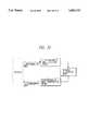
- FIG. 1is a schematic diagram showing a radar system in accordance with a first embodiment of the present invention
- FIG. 2is a flowchart showing a main routine in an obstacle detecting process in accordance with the first embodiment of the present invention
- FIG. 3is a flowchart showing an interrupt routine of the obstacle detecting process in accordance with the first embodiment of the present invention
- FIG. 4is a flowchart showing a measuring time setting routine of the interrupt routine in accordance with the first embodiment of the present invention
- FIG. 5is a flowchart showing an anti-collision process in accordance with the first embodiment of the present invention.
- FIG. 6is a time chart illustrating the procedure of the obstacle detecting process of the first embodiment of the present invention.
- FIGS. 7A and 7bare views showing the relationship between an automotive vehicle equipped with the radar system in accordance with the first embodiment of the present invention.
- FIGS. 8A and 8Bare time charts respectively showing an output voltage of the variable gain amplifier in accordance with the first embodiment of the present invention.
- FIGS. 9A and 9Bare time charts illustrating detection of the distances of preceding vehicles from the radar
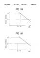
- FIGS. 10A and 10Bare graphs showing limitations of the detecting capability of the radar system in accordance with the first embodiment of the present invention.
- FIGS. 11A and 11Bare time charts showing the output voltage of a conventional radar system.
- FIG. 12is a schematic view illustrating the arrangement of the present invention.
- FIG. 1is a schematic diagram showing a radar system 1 in accordance with the first embodiment, which is installed in an automatic vehicle to detect an object (obstacle) existing in of the direction the automatic vehicle.
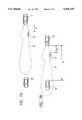
- the radar system 1comprises a semiconductor laser diode 3 acting as electromagnetic wave transmission means for emitting a semiconductor laser beam H having a pulse waveform, and a light receiving element 5 acting as electromagnetic wave reception means for receiving the semiconductor laser beam H reflected from the object (obstacle), which is not shown, and generating a voltage corresponding to the intensity of the semiconductor laser beam H received.
- the laser diode 3which is connected to an electronic control circuit (CPU) 9 via a drive circuit 7, emits the semiconductor laser beam H in response to a drive signal given from the electronic control circuit 9. Meanwhile, an output voltage of the light receiving element 5 is amplified to a predetermined level through a preamplifier 11 and thereafter supplied to a variable gain amplifier 13.
- the comparator 17compares the output voltage V of the variable gain amplifier 13 with a reference voltage V0, and sends a predetermined light receiving signal to a time interval measuring circuit 21 when the output voltage V exceeds the reference voltage V0.
- the time interval measuring circuit 21receives the drive signal given from the electronic control circuit 9 to the drive circuit 7.
- the time interval measuring circuit 21,which is a well-known type constituted by a plurality of integrated circuits (ICs), measures a time interval between transmission of the drive signal and reception of the light receiving signal, and sends the thus measured time interval as distance data to the electronic control circuit 9.
- the electronic control circuit 9calculates the distance of the object (obstacle) measured from the radar system. That is, the time interval measuring circuit 21 and the electronic control circuit 9 cooperatively constitute distance calculating means.
- the output voltage V of the variable gain amplifier 13is input to a window comparator 23 which compares the output voltage V of the variable gain amplifier 13 with each of two predetermined higher voltages V1 and V2.
- the voltages V1 and V2are fairly larger than the reference voltage V0 and voltage V2 is slightly larger than voltage V1.
- the comparison result of the window comparator 23is sent to the electronic control circuit 9.
- the electronic control circuit 9is connected to a warning device 25 that generates an alarm using light, sound and other warning indicators.
- the electronic control circuit 9gives a warning to a driver of the vehicle having the radar system as soon as the system detects an obstacle in the forward direction of the vehicle.
- FIG. 2is a flowchart showing a main routine of an obstacle detecting process in accordance with a first embodiment of the present invention, executed by the electronic control circuit (CPU) 9 upon an electric power source beginning supplying electric power to the radar system 1.
- FIGS. 3 and 4are flowcharts showing interrupt routines of the obstacle detecting process, which is periodically executed at predetermined intervals during execution of the main routine.
- the CPU 9sets a full gain flag FF to "1" in a step 101 as shown in FIG. 2. Then, the CPU 9 proceeds to a step 105 which sets a first waiting period equivalent to an elapse of 16 msec.
- the full gain flag FFis reset to "0" together with an AGC flag FA later described at the moment the electric power source starts supplying electric power to the radar system 1.
- the CPU 9supplies the drive circuit 7 with a drive signal to emit a laser beam from the laser diode 3.
- the CPU 9receives a distance data supplied from the time interval measuring circuit 21 which is generated in response to the reception of the laser beam reflected from an obstacle.
- the CPU 9has a RAM, not shown in the drawing, for memorizing this distance data.
- a judgementis made as to whether or not the AGC flag FA is set to "1". As the AGC flag FA is not "1" at this moment, the CPU 9 proceeds to a step 300.
- the CPU 9determines a next measuring time for executing this interrupt routine next by using a measuring time setting routine later described. After that, the CPU 9 ends the present processing cycle and returns to the main routine of FIG. 2.
- the CPU 9After the passage of first 16 msec period in the step 105, the CPU 9 proceeds to a step 110 to reset the full gain flag FF to "0" and set the AGC flag FA to "1".
- the CPU 9takes an average of the distance data memorized in the step 230 of the previously explained interrupt routine and calculates a distance (i.e. a full gain distance) of an obstacle measured from the vehicle on the basis of the average obtained.
- a relative speedi.e. a full gain relative speed
- the CPU 9proceeds to a step 125 which sets a second waiting period equivalent to an elapse of 16 msec in the same manner as the step 105.
- the interrupt routine of FIG. 3is executed again.
- the CPU 9proceeds to a step 240 to further make a judgement as to whether or not the AGC flag FA is already set to "1".
- the CPU 9proceeds to a step 245 to set the gain of the variable gain amplifier 13 to be a memorized value and subsequently proceeds to steps 220, 230 and 235.
- the memorized value in this caseis a value memorized in a step 270 later described.
- step 250a judgement is made based on the output of the window comparator 23 as to whether or not the maximum value Vmax of the output voltage V of the variable gain amplifier 13 is larger than the predetermined voltage V1. If the result of judgement is "YES”, the CPU 9 proceeds to a step 255 to further make a judgement as to whether or not the maximum value Vmax is smaller than the predetermined value V2. Thereafter, the CPU 9 proceeds to a step 270. When the maximum value Vmax is not larger than the predetermined voltage V1 ("NO" in the step 250), the CPU 9 proceeds to a step 260 to correct the gain of the variable gain amplifier 13 by increasing its value, and then proceeds to the step 270.
- the CPU 9proceeds to a step 265 to correct the gain of the variable gain amplifier 13 by decreasing its value, and then proceeds to the step 270.
- the CPU 9proceeds to the step 270 without correcting the gain of the variable gain amplifier 13.
- the CPU 9memorizes a present gain value in the RAM.
- these steps 250-270realizes AGC (automatic gain control) so as to adjust the gain of the variable gain amplifier 13 to satisfy a relation V1 ⁇ Vmax ⁇ V2. After that, the CPU 9 proceeds to a step 300.
- the CPU 9makes a judgement in a step 1451 as to whether or not a difference between the AGC distance D A and the full gain distance D F is larger than a predetermined distance (e.g. 5 m) with respect to the nearest obstacle. If the result of judgement in the step 1451 is "YES”, the CPU 9 adopts the full gain distance D F as a true distance D T in a step 1453. On the contrary, if the result of judgement in the step 1451 is "NO", the CPU 9 adopts the AGC distance D A as the true distance D T in a step 1455.
- a predetermined distancee.g. 5 m
- this embodimentchecks whether or not the difference between the AGC distance D A and the full gain distance D F is sufficiently small. More specifically, if the difference between the AGC distance D A and the full gain distance D F is not negligible, the CPU 9 judges that detection of an obstacle having a smaller reflectance has failed in the AGC distance calculating method because the AGC method has a large possibility of missing a small reflectance object when a large reflectance object exists in the same detection area as explained previously.
- the CPU 9adopts the AGC distance D A as the true distance D T when the difference between the AGC distance D A and the full gain distance D F is small, while the full gain distance D F is adopted as the true distance D T only when the difference between the AGC distance D A and the full gain distance D F is larger than the predetermined value. Subsequently, the CPU 9 proceeds to a step 1457 to further make a judgement as to whether or not the true distance D T is smaller than a predetermined safe distance (e.g. 35 m). If the result of judgement is "YES" in the step 1457, the CPU 9 proceeds to a succeeding step 1459 to actuate the warning device 25 to generate alarm.
- a predetermined safe distancee.g. 35 m
- the CPU 9After finishing such an anti-collision processing in the step 145, the CPU 9 proceeds to a step 150 which sets a third waiting period equivalent to an elapse of 16 msec. Namely, a judgement is made as to whether or not a third 16 msec period has passed after entering the step 130. If this third 16 msec period has passed, the CPU returns to the first step 101. During this third 16 msec period, the interrupt routine of FIG. 3 is executed again. In this case, judgements in the steps 205 and 240 are both "NO"; therefore, the CPU 9 directly goes to the step 300 to set the next measuring time.
- next measuring time setting routine of the step 300Details of the next measuring time setting routine of the step 300 will be explained with reference to FIG. 4.
- the CPU 9reads in both the full gain distance and the AGC distance in a step 301. (A predetermined value will be used in the event any one of these distances has not yet been calculated.)
- the next step 303a judgement is made based on the full gain and AGC distances as to whether or not accuracy is required. For example, if the true distance D T is smaller than the predetermined safe distance (i.e. 35 m), the CPU 9 judges that accuracy is necessary. In this case, it is preferable that the safe distance is varied in accordance with the vehicle speed.
- the CPU 9proceeds to a step 305 to set a processing period of the FIG. 3 interrupt routine longer (e.g. 48 cycles during a 16 msec period).
- the CPU 9proceeds to a step 307 to set the processing period of the FIG. 3 interrupt routine shorter (e.g. 60 cycles during a 16 msec period). Then, the CPU 9 proceeds to a step 309 to set the next measuring time and thereafter ends this routine.
- the processing period of the interrupt routineWhen the processing period of the interrupt routine is shortened to increase the accuracy of the detection, the total number of distance data stored in the step 230 during the waiting periods of 105 and 125 increases. This assures that the calculations in the steps 115, 120, 135 and 140 obtain accurate results on the basis of numerous distance data. 0n the other hand, when the processing period of the interrupt routine is enlarged, a total number of light emission in the laser diode 3 can be significantly decreased, thereby increasing durability of the laser diode 3.
- FIG. 6omits the anti-collision processing.
- the obstacle detecting process of the present embodimentrepeats the similar processing at the intervals of 48 msec.
- This 48 msec periodis divided into three 16 msec sections.
- a first 16 msec section(a time interval of t11-t22) executes the full gain measurement; namely, the laser diode 3 is repeatedly actuated with the gain of the variable gain amplifier 13 fixed at the maximum value (Full).
- Fullmaximum value
- 48 times measurementsare intermittently and successively executed during this first 16 msec section.
- a distance data obtained in each measurementis memorized in the RAM.
- the AGC measurementis executed by flexibly varying the gain of the variable gain amplifier 13.
- both the full gain distance calculation processing and the full gain relative speed calculation processingare carried out on the basis of the distance data memorized during the first 16 msec section (t11-t22).
- both the AGC distance calculation processing and the AGC relative speed calculation processingare carried out on the basis of the distance data memorized during the second 16 msec section (t22-t33).
- the previously described anti-collision processingis carried out in this third 16 msec section.
- FIG. 7Ais a plan view illustrating a condition where an automotive vehicle 51 equipped with the radar system 1 is following a preceding motorcycle 53 traveling with a constant distance D kept therebetween, while the automotive vehicle 51 is gradually approaching a preceding automotive vehicle 55.
- FIG. 7Bis a similar plan view showing a predetermined time later condition of these automotive vehicle 51, the motorcycle 53 and the automotive vehicle 55.
- FIG. 7A conditionshows the motorcycle 53 captured in the detection area 57 of the radar system 1, although the preceding automotive vehicle 55 is out of the detection area 57.
- FIG. 7Bshows the automotive vehicle 55 and the motorcycle 53 both captured in the detection area 57 of the radar system 1.
- FIGS. 8A and 8Bare time charts showing the output voltage V of the variable gain amplifier 13 in the condition of FIG. 7B.
- FIG. 8Ashows the output voltage V obtained as a result of the AGC method flexibly controlling the gain of the variable gain amplifier 13.
- a semiconductor laser beam H reflected from the automotive vehicle 55is stronger in its intensity than a semiconductor laser beam H reflected from the motorcycle 53.
- a small peak P53represents an output voltage corresponding to the semiconductor laser beam H reflected from the motorcycle 53.
- a large peak P55represents an output voltage corresponding to the semiconductor laser beam H reflected from the automotive vehicle 55.
- the AGCis a technology amplifying the maximum voltage value Vmax to be somewhere between the predetermined higher voltages V1 and V2.
- the AGC-based control of the variable gain amplifier 13possibly fails to detect the motorcycle 53 in tile above particular situation.
- the radar system 1detects the preceding motorcycle 53 spaced a distance D from the automotive vehicle 51 at the time (Ta) the automotive vehicle 55 is out of the detection area 57.
- the radar system 1fails to detect the preceding motorcycle 53 spaced a distance D from the automotive vehicle 51 at the time (Tb) the automotive vehicle 55 is captured in the detection area 57, although detecting only the automotive vehicle 55 spaced a distance D1 from the automotive vehicle 51.
- FIG. 8Bis a time chart showing the output voltage V obtained when the gain of the variable gain amplifier 13 is fixed to the maximum value (full gain).
- a full gain measuringenables the small peak P53 to always exceed the reference voltage V0. Therefore, it becomes possible to reliably detect the existence of the motorcycle 53.
- the large peak P55reaches the saturated voltage V3 of the variable gain amplifier 13, having a flat top in its waveform. In this manner, controlling the gain of the variable gain amplifier 13 to the full gain assures the detection of both the motorcycle 53 and the automotive vehicle 55.
- the automotive vehicle 55enters the detection area 57 of the radar system 1, both the distance D of the motorcycle 53 and the distance D1 of the automotive vehicle 55 are detected.
- the full gain distance and the full gain relative speed obtained in this mannerinclude large measuring errors compared with the previously described AGC distance and the AGC relative speed.
- the radar system 1 of the present embodimentexecutes the AGC based detection and the full-gain based detection alternately.
- the radar system 1 of the present embodimentnot only reliably detects the presence of both the motorcycle 53 and the automotive vehicle 55 using the full-gain based detecting method but also accurately detects the true distance and the relative speed of the automotive vehicle 55 having a large reflectance using the AGC based detecting method.
- FIGS. 10A and 10Bshow limitations capable of detecting another same reflective mirror under the condition that a circular reflective mirror of 51 mm is placed at a 40 m ahead position of the radar system 1.
- An abscissa of FIG. 10Arepresents distances in the right and left direction
- an abscissa of FIG. 10Brepresents distances in the up-and-down direction.
- the AGC based detectionhas narrow limitations compared with the limitations of an alternate long and dash line.
- the alternate long and dash linecorresponds to a case where no reflective mirror is placed in front of the radar system 1.
- the similar resultis obtained irrespective of the difference between the AGC based detection and the full gain based detection.
- the full gain based detectionhas substantially the same limitations as those of the alternate long and dash line. Therefore, it is understood that the AGC based detection possibly fails to detect an object out of its centrally narrowed limitations in the right and left direction, while the full gain based detection provides sufficiently wide detecting limitations.
- the limitations in the up-and-down direction shown in FIGS. 10Bthere was not found substantial difference among three detections above described.
- the electronic control circuit 9 of the above-described embodimentexecutes the anti-collision processing on the basis of distance data calculated
- various processingcan be executed additionally. For example, keeping a constant-distance between the preceding vehicle and the radar system will be acceptable.
- the radar system 1 of the present inventioncan be applied to various apparatuses other than automotive vehicles.
- the radar system 1 of the present inventionis not limited to the above-described embodiment.
- the output voltage V of the variable gain amplifier 13can be A/D converted and then directly supplied to the electronic control circuit 9, so that the electronic control circuit 9 can execute various processing in response to the output voltage V.
- two variable gain amplifiers 13, 13can be provided so that the AGC based detection and the full gain based detection can be simultaneously and independently carried out, assuring speediness and accuracy in the detection.
- the above-described embodimentutilizes the semiconductor laser beam H to detect an obstacle, it is needless to say that other electromagnetic wave such as microwave and infrared ray can be used.
- the above-described embodimentcontrols the gain of the variable gain amplifier 13 to take its maximum value to maximize the sensitivity of the semiconductor laser H, it is possible to vary the reference voltage V0 of the comparator 17 so that the reference voltage V0 is lowered sufficiently enough to detect the obstacle. Furthermore, by varying the reference voltage V0 in accordance with Vmax, it becomes possible to reduce the measuring error of distance as well as AGC.
- the radar system of the present inventionallows the electromagnetic wave reception means to use both a standard sensitivity corresponding to the maximum value of the electromagnetic wave received and a maximum sensitivity of the electromagnetic wave reception means. Accordingly, the present invention not only surely detects the presence of all the obstacles in the detection area using the maximum sensitivity but also accurately detects the true distance of the obstacle reflecting the largest electromagnetic wave using the standard sensitivity.
Landscapes
- Engineering & Computer Science (AREA)
- Physics & Mathematics (AREA)
- Computer Networks & Wireless Communication (AREA)
- General Physics & Mathematics (AREA)
- Radar, Positioning & Navigation (AREA)
- Remote Sensing (AREA)
- Electromagnetism (AREA)
- Optical Radar Systems And Details Thereof (AREA)
- Radar Systems Or Details Thereof (AREA)
Abstract
Description
Claims (20)
Applications Claiming Priority (2)
| Application Number | Priority Date | Filing Date | Title |
|---|---|---|---|
| JP05295340AJP3106045B2 (en) | 1993-11-25 | 1993-11-25 | Radar equipment |
| JP5-295340 | 1993-11-25 |
Publications (1)
| Publication Number | Publication Date |
|---|---|
| US5485155Atrue US5485155A (en) | 1996-01-16 |
Family
ID=17819353
Family Applications (1)
| Application Number | Title | Priority Date | Filing Date |
|---|---|---|---|
| US08/346,297Expired - Fee RelatedUS5485155A (en) | 1993-11-25 | 1994-11-23 | Radar system detecting plural obstacles and measuring distance based on full gain and automatic gain control |
Country Status (2)
| Country | Link |
|---|---|
| US (1) | US5485155A (en) |
| JP (1) | JP3106045B2 (en) |
Cited By (70)
| Publication number | Priority date | Publication date | Assignee | Title |
|---|---|---|---|---|
| DE19804957A1 (en)* | 1998-02-07 | 1999-08-12 | Itt Mfg Enterprises Inc | Distance measurement method with adaptive amplification |
| US6018308A (en)* | 1997-07-23 | 2000-01-25 | Denso Corporation | Obstacle recognition system for automotive vehicle |
| US6025797A (en)* | 1997-07-22 | 2000-02-15 | Denso Corporation | Angular shift determining apparatus for determining angular shift of central axis of radar used in automotive obstacle detection system |
| US6031421A (en)* | 1998-07-22 | 2000-02-29 | Mcewan; Thomas E. | Controlled gain amplifier with variable control exponent |
| US6147637A (en)* | 1997-07-23 | 2000-11-14 | Denso Corporation | Obstacle detecting system for automotive vehicle |
| US6265990B1 (en) | 1998-07-17 | 2001-07-24 | Denso Corporation | Apparatus and method for controlling a distance between two traveling vehicles and a recording medium for storing the control method |
| US6327530B1 (en) | 1998-07-13 | 2001-12-04 | Denso Corporation | Apparatus and method for controlling a distance between two traveling vehicles and a recording medium for storing the control method |
| US20020044082A1 (en)* | 2000-08-16 | 2002-04-18 | Woodington Walter Gordon | Radar detection method and apparatus |
| US20020049539A1 (en)* | 2000-09-08 | 2002-04-25 | Russell Mark E. | Path prediction system and method |
| US20020067287A1 (en)* | 2000-08-16 | 2002-06-06 | Delcheccolo Michael Joseph | Near object detection system |
| US20020072843A1 (en)* | 2000-08-16 | 2002-06-13 | Russell Mark E. | Safe distance algorithm for adaptive cruise control |
| US20020075138A1 (en)* | 2000-08-16 | 2002-06-20 | Van Rees H. Barteld | Portable object detection system |
| US6418370B1 (en) | 1998-08-04 | 2002-07-09 | Denso Corporation | Apparatus and method for controlling a target distance and a warning distance between traveling vehicles and a recording medium for storing the control method |
| US20020163478A1 (en)* | 2000-08-16 | 2002-11-07 | Pleva Joseph S. | Switched beam antenna architecture |
| US20030004633A1 (en)* | 2001-03-14 | 2003-01-02 | Russell Mark E. | Safe distance algorithm for adaptive cruise control |
| US20030036881A1 (en)* | 2000-06-22 | 2003-02-20 | Ford Global Technologies, Inc. | System and method for detecting an object using pulsed light |
| US20030098816A1 (en)* | 2001-08-16 | 2003-05-29 | Pleva Joseph S. | Antenna configurations for reduced radar complexity |
| US20030107323A1 (en)* | 1998-09-18 | 2003-06-12 | Stam Joseph S. | Headlamp control to prevent glare |
| US6611227B1 (en) | 2002-08-08 | 2003-08-26 | Raytheon Company | Automotive side object detection sensor blockage detection system and related techniques |
| US20030210172A1 (en)* | 2000-08-16 | 2003-11-13 | Pleva Joseph S. | Technique for changing a range gate and radar coverage |
| US20030210182A1 (en)* | 2000-08-16 | 2003-11-13 | Hanson James T. | Video amplifier for a radar receiver |
| US20040008110A1 (en)* | 1998-09-18 | 2004-01-15 | Stam Joseph S. | Continuously variable headlamp control |
| US20040034457A1 (en)* | 2001-03-05 | 2004-02-19 | Stam Joseph S. | Image processing system to control vehicle headlamps or other vehicle equipment |
| US20040031907A1 (en)* | 1998-06-09 | 2004-02-19 | Bechtel Jon H. | Imaging system for vehicle headlamp control |
| US6970142B1 (en) | 2001-08-16 | 2005-11-29 | Raytheon Company | Antenna configurations for reduced radar complexity |
| US20060091813A1 (en)* | 1997-04-02 | 2006-05-04 | Stam Joseph S | Control system to automatically control vehicle headlamps |
| US7183995B2 (en) | 2001-08-16 | 2007-02-27 | Raytheon Company | Antenna configurations for reduced radar complexity |
| US20070205938A1 (en)* | 2000-03-08 | 2007-09-06 | Uwe Zimmermann | Object Detection System |
| US7333183B2 (en)* | 2005-12-08 | 2008-02-19 | Omron Corporation | Laser scanning device |
| US20080136702A1 (en)* | 2006-08-10 | 2008-06-12 | Fujitsu Ten Limited | Radar device |
| US20090243912A1 (en)* | 2008-03-31 | 2009-10-01 | Lohmeier Stephen P | Automotive Radar Sensor Blockage Detection System and Related Techniques |
| US20090271087A1 (en)* | 2006-11-29 | 2009-10-29 | Yutaka Motonaga | Control device and engine control device |
| US7653215B2 (en) | 1997-04-02 | 2010-01-26 | Gentex Corporation | System for controlling exterior vehicle lights |
| US20110026571A1 (en)* | 2008-04-14 | 2011-02-03 | Electronics And Telecommunications Research Institute | Automatic gain controller, transceiver and automatic gain-control method thereof |
| CN101978286A (en)* | 2008-03-20 | 2011-02-16 | 特林布尔公司 | Geodetic scanner with increased efficiency |
| US8879139B2 (en) | 2012-04-24 | 2014-11-04 | Gentex Corporation | Display mirror assembly |
| US8964024B2 (en) | 2012-08-02 | 2015-02-24 | Gentex Corporation | System and method for controlling exterior vehicle lights responsive to detection of a semi-truck |
| US8977439B2 (en) | 2012-06-12 | 2015-03-10 | Genetex Corporation | Vehicle imaging system providing multi-stage aiming stability indication |
| US8983135B2 (en) | 2012-06-01 | 2015-03-17 | Gentex Corporation | System and method for controlling vehicle equipment responsive to a multi-stage village detection |
| US9187029B2 (en) | 2013-10-01 | 2015-11-17 | Gentex Corporation | System and method for controlling exterior vehicle lights on motorways |
| US9317758B2 (en) | 2013-08-19 | 2016-04-19 | Gentex Corporation | Vehicle imaging system and method for distinguishing reflective objects from lights of another vehicle |
| US9434327B2 (en) | 2013-11-15 | 2016-09-06 | Gentex Corporation | Imaging system including dynamic compensation for color attenuation for vehicle windscreens |
| US9511715B2 (en) | 2014-01-31 | 2016-12-06 | Gentex Corporation | Backlighting assembly for display for reducing cross-hatching |
| US9575315B2 (en) | 2013-09-24 | 2017-02-21 | Gentex Corporation | Display mirror assembly |
| US9619720B2 (en) | 2013-08-19 | 2017-04-11 | Gentex Corporation | Vehicle imaging system and method for distinguishing between vehicle tail lights and flashing red stop lights |
| USD783480S1 (en) | 2014-12-05 | 2017-04-11 | Gentex Corporation | Rearview device |
| US9694751B2 (en) | 2014-09-19 | 2017-07-04 | Gentex Corporation | Rearview assembly |
| US9694752B2 (en) | 2014-11-07 | 2017-07-04 | Gentex Corporation | Full display mirror actuator |
| US9720278B2 (en) | 2015-01-22 | 2017-08-01 | Gentex Corporation | Low cost optical film stack |
| US9744907B2 (en) | 2014-12-29 | 2017-08-29 | Gentex Corporation | Vehicle vision system having adjustable displayed field of view |
| USD797627S1 (en) | 2015-10-30 | 2017-09-19 | Gentex Corporation | Rearview mirror device |
| USD798207S1 (en) | 2015-10-30 | 2017-09-26 | Gentex Corporation | Rearview mirror assembly |
| USD800618S1 (en) | 2015-11-02 | 2017-10-24 | Gentex Corporation | Toggle paddle for a rear view device |
| US9834146B2 (en) | 2014-04-01 | 2017-12-05 | Gentex Corporation | Automatic display mirror assembly |
| USD809984S1 (en) | 2016-12-07 | 2018-02-13 | Gentex Corporation | Rearview assembly |
| USD817238S1 (en) | 2016-04-29 | 2018-05-08 | Gentex Corporation | Rearview device |
| US9995854B2 (en) | 2015-04-20 | 2018-06-12 | Gentex Corporation | Rearview assembly with applique |
| US9994156B2 (en) | 2015-10-30 | 2018-06-12 | Gentex Corporation | Rearview device |
| US10025138B2 (en) | 2016-06-06 | 2018-07-17 | Gentex Corporation | Illuminating display with light gathering structure |
| US10071689B2 (en) | 2014-11-13 | 2018-09-11 | Gentex Corporation | Rearview mirror system with a display |
| US10112540B2 (en) | 2015-05-18 | 2018-10-30 | Gentex Corporation | Full display rearview device |
| US10131279B2 (en) | 2014-12-03 | 2018-11-20 | Gentex Corporation | Display mirror assembly with an RF shield bezel |
| USD845851S1 (en) | 2016-03-31 | 2019-04-16 | Gentex Corporation | Rearview device |
| USD854473S1 (en) | 2016-12-16 | 2019-07-23 | Gentex Corporation | Rearview assembly |
| US10685623B2 (en) | 2015-10-30 | 2020-06-16 | Gentex Corporation | Toggle paddle |
| US10705332B2 (en) | 2014-03-21 | 2020-07-07 | Gentex Corporation | Tri-modal display mirror assembly |
| US10735638B2 (en) | 2017-03-17 | 2020-08-04 | Gentex Corporation | Dual display reverse camera system |
| US11178353B2 (en) | 2015-06-22 | 2021-11-16 | Gentex Corporation | System and method for processing streamed video images to correct for flicker of amplitude-modulated lights |
| US11800050B2 (en) | 2016-12-30 | 2023-10-24 | Gentex Corporation | Full display mirror with on-demand spotter view |
| US11994272B2 (en) | 2021-08-20 | 2024-05-28 | Gentex Corporation | Lighting assembly and illumination system having a lighting assembly |
Families Citing this family (1)
| Publication number | Priority date | Publication date | Assignee | Title |
|---|---|---|---|---|
| US7599671B2 (en)* | 2005-08-08 | 2009-10-06 | Marvell World Trade Ltd. | Radar detection apparatus and method thereof |
Citations (11)
| Publication number | Priority date | Publication date | Assignee | Title |
|---|---|---|---|---|
| US3749197A (en)* | 1971-05-12 | 1973-07-31 | B Deutsch | Obstacle detection system |
| US3772690A (en)* | 1971-12-07 | 1973-11-13 | Sperry Rand Corp | Vehicle safety apparatus |
| US3934252A (en)* | 1974-04-08 | 1976-01-20 | Sperry Rand Corporation | Closed loop tunnel diode receiver for operation with a base band semiconductor transmitter |
| US4039782A (en)* | 1974-10-25 | 1977-08-02 | Daimler-Benz Aktiengesellschaft | Installation for controlling a measuring beam and/or a light beam in motor vehicles |
| JPS5999376A (en)* | 1982-11-30 | 1984-06-08 | Nippon Soken Inc | Apparatus for detecting obstacle |
| US4551722A (en)* | 1982-03-16 | 1985-11-05 | Nippondenso Co., Ltd. | Apparatus and method for detecting obstacles in the path of a moving vehicle |
| US4552456A (en)* | 1981-10-31 | 1985-11-12 | Nissan Motor Company, Limited | Optical pulse radar for an automotive vehicle |
| US4641136A (en)* | 1985-04-18 | 1987-02-03 | Thaddeus Kowalczyk | Security eyes for prevention of car accidents |
| US4757450A (en)* | 1985-06-03 | 1988-07-12 | Nissan Motor Company, Limited | Method and system for automatically detecting a preceding vehicle |
| US4926171A (en)* | 1988-11-21 | 1990-05-15 | Kelley William L | Collision predicting and avoidance device for moving vehicles |
| US5260710A (en)* | 1991-01-31 | 1993-11-09 | Stanley Electric Co., Ltd. | Vehicular optical-radar apparatus |
- 1993
- 1993-11-25JPJP05295340Apatent/JP3106045B2/ennot_activeExpired - Fee Related
- 1994
- 1994-11-23USUS08/346,297patent/US5485155A/ennot_activeExpired - Fee Related
Patent Citations (11)
| Publication number | Priority date | Publication date | Assignee | Title |
|---|---|---|---|---|
| US3749197A (en)* | 1971-05-12 | 1973-07-31 | B Deutsch | Obstacle detection system |
| US3772690A (en)* | 1971-12-07 | 1973-11-13 | Sperry Rand Corp | Vehicle safety apparatus |
| US3934252A (en)* | 1974-04-08 | 1976-01-20 | Sperry Rand Corporation | Closed loop tunnel diode receiver for operation with a base band semiconductor transmitter |
| US4039782A (en)* | 1974-10-25 | 1977-08-02 | Daimler-Benz Aktiengesellschaft | Installation for controlling a measuring beam and/or a light beam in motor vehicles |
| US4552456A (en)* | 1981-10-31 | 1985-11-12 | Nissan Motor Company, Limited | Optical pulse radar for an automotive vehicle |
| US4551722A (en)* | 1982-03-16 | 1985-11-05 | Nippondenso Co., Ltd. | Apparatus and method for detecting obstacles in the path of a moving vehicle |
| JPS5999376A (en)* | 1982-11-30 | 1984-06-08 | Nippon Soken Inc | Apparatus for detecting obstacle |
| US4641136A (en)* | 1985-04-18 | 1987-02-03 | Thaddeus Kowalczyk | Security eyes for prevention of car accidents |
| US4757450A (en)* | 1985-06-03 | 1988-07-12 | Nissan Motor Company, Limited | Method and system for automatically detecting a preceding vehicle |
| US4926171A (en)* | 1988-11-21 | 1990-05-15 | Kelley William L | Collision predicting and avoidance device for moving vehicles |
| US5260710A (en)* | 1991-01-31 | 1993-11-09 | Stanley Electric Co., Ltd. | Vehicular optical-radar apparatus |
Cited By (113)
| Publication number | Priority date | Publication date | Assignee | Title |
|---|---|---|---|---|
| US20060091813A1 (en)* | 1997-04-02 | 2006-05-04 | Stam Joseph S | Control system to automatically control vehicle headlamps |
| US7653215B2 (en) | 1997-04-02 | 2010-01-26 | Gentex Corporation | System for controlling exterior vehicle lights |
| US6025797A (en)* | 1997-07-22 | 2000-02-15 | Denso Corporation | Angular shift determining apparatus for determining angular shift of central axis of radar used in automotive obstacle detection system |
| US6018308A (en)* | 1997-07-23 | 2000-01-25 | Denso Corporation | Obstacle recognition system for automotive vehicle |
| US6147637A (en)* | 1997-07-23 | 2000-11-14 | Denso Corporation | Obstacle detecting system for automotive vehicle |
| DE19804957A1 (en)* | 1998-02-07 | 1999-08-12 | Itt Mfg Enterprises Inc | Distance measurement method with adaptive amplification |
| US6094159A (en)* | 1998-02-07 | 2000-07-25 | Itt Manufacturing Enterprises, Inc. | Process for measuring distance with adaptive amplification |
| US20040031907A1 (en)* | 1998-06-09 | 2004-02-19 | Bechtel Jon H. | Imaging system for vehicle headlamp control |
| US6924470B2 (en) | 1998-06-09 | 2005-08-02 | Gentex Corporation | Vehicle vision system |
| US6327530B1 (en) | 1998-07-13 | 2001-12-04 | Denso Corporation | Apparatus and method for controlling a distance between two traveling vehicles and a recording medium for storing the control method |
| US6265990B1 (en) | 1998-07-17 | 2001-07-24 | Denso Corporation | Apparatus and method for controlling a distance between two traveling vehicles and a recording medium for storing the control method |
| US6031421A (en)* | 1998-07-22 | 2000-02-29 | Mcewan; Thomas E. | Controlled gain amplifier with variable control exponent |
| US6418370B1 (en) | 1998-08-04 | 2002-07-09 | Denso Corporation | Apparatus and method for controlling a target distance and a warning distance between traveling vehicles and a recording medium for storing the control method |
| US20050073853A1 (en)* | 1998-09-18 | 2005-04-07 | Stam Joseph S. | Headlamp control to prevent glare |
| US20030107323A1 (en)* | 1998-09-18 | 2003-06-12 | Stam Joseph S. | Headlamp control to prevent glare |
| US20040008110A1 (en)* | 1998-09-18 | 2004-01-15 | Stam Joseph S. | Continuously variable headlamp control |
| US6861809B2 (en) | 1998-09-18 | 2005-03-01 | Gentex Corporation | Headlamp control to prevent glare |
| US6906467B2 (en) | 1998-09-18 | 2005-06-14 | Gentex Corporation | Continuously variable headlamp control |
| US20070205938A1 (en)* | 2000-03-08 | 2007-09-06 | Uwe Zimmermann | Object Detection System |
| US7554484B2 (en)* | 2000-03-08 | 2009-06-30 | Robert Bosch Gmbh | Object detection system |
| US7079974B2 (en)* | 2000-06-22 | 2006-07-18 | Ford Global Technologies, Llc | System and method for detecting an object using pulsed light |
| US20030036881A1 (en)* | 2000-06-22 | 2003-02-20 | Ford Global Technologies, Inc. | System and method for detecting an object using pulsed light |
| US20020072843A1 (en)* | 2000-08-16 | 2002-06-13 | Russell Mark E. | Safe distance algorithm for adaptive cruise control |
| US20020075138A1 (en)* | 2000-08-16 | 2002-06-20 | Van Rees H. Barteld | Portable object detection system |
| US6642908B2 (en) | 2000-08-16 | 2003-11-04 | Raytheon Company | Switched beam antenna architecture |
| US20030210172A1 (en)* | 2000-08-16 | 2003-11-13 | Pleva Joseph S. | Technique for changing a range gate and radar coverage |
| US20030210182A1 (en)* | 2000-08-16 | 2003-11-13 | Hanson James T. | Video amplifier for a radar receiver |
| US6670910B2 (en) | 2000-08-16 | 2003-12-30 | Raytheon Company | Near object detection system |
| US20020044082A1 (en)* | 2000-08-16 | 2002-04-18 | Woodington Walter Gordon | Radar detection method and apparatus |
| US20030001772A1 (en)* | 2000-08-16 | 2003-01-02 | Woodington Walter Gordon | Radar detection method and apparatus |
| US6683557B2 (en) | 2000-08-16 | 2004-01-27 | Raytheon Company | Technique for changing a range gate and radar for coverage |
| US20020163478A1 (en)* | 2000-08-16 | 2002-11-07 | Pleva Joseph S. | Switched beam antenna architecture |
| US20020147534A1 (en)* | 2000-08-16 | 2002-10-10 | Delcheccolo Michael Joseph | Near object detection system |
| US6707419B2 (en) | 2000-08-16 | 2004-03-16 | Raytheon Company | Radar transmitter circuitry and techniques |
| US20020075178A1 (en)* | 2000-08-16 | 2002-06-20 | Woodington Walter Gordon | Radar transmitter circuitry and techniques |
| US6784828B2 (en) | 2000-08-16 | 2004-08-31 | Raytheon Company | Near object detection system |
| US20040246170A1 (en)* | 2000-08-16 | 2004-12-09 | Woodington Walter Gordon | Radar detection method and apparatus |
| US20040257266A1 (en)* | 2000-08-16 | 2004-12-23 | Pleva Joseph S. | Technique for changing a range gate and radar coverage |
| US6577269B2 (en) | 2000-08-16 | 2003-06-10 | Raytheon Company | Radar detection method and apparatus |
| US6864831B2 (en) | 2000-08-16 | 2005-03-08 | Raytheon Company | Radar detection method and apparatus |
| US7071868B2 (en) | 2000-08-16 | 2006-07-04 | Raytheon Company | Radar detection method and apparatus |
| US6977609B2 (en) | 2000-08-16 | 2005-12-20 | Raytheon Company | Technique for changing a range gate and radar coverage |
| US6903679B2 (en) | 2000-08-16 | 2005-06-07 | Raytheon Company | Video amplifier for a radar receiver |
| US20020067287A1 (en)* | 2000-08-16 | 2002-06-06 | Delcheccolo Michael Joseph | Near object detection system |
| US20020049539A1 (en)* | 2000-09-08 | 2002-04-25 | Russell Mark E. | Path prediction system and method |
| US6675094B2 (en) | 2000-09-08 | 2004-01-06 | Raytheon Company | Path prediction system and method |
| US7302326B2 (en) | 2001-03-05 | 2007-11-27 | Gentex Corporation | Image processing system to control vehicle headlamps or other vehicle equipment |
| US7149613B2 (en) | 2001-03-05 | 2006-12-12 | Gentex Corporation | Image processing system to control vehicle headlamps or other vehicle equipment |
| US20040034457A1 (en)* | 2001-03-05 | 2004-02-19 | Stam Joseph S. | Image processing system to control vehicle headlamps or other vehicle equipment |
| US20050165526A1 (en)* | 2001-03-05 | 2005-07-28 | Stam Joseph S. | Image processing system to control vehicle headlamps or other vehicle equipment |
| US6868322B2 (en) | 2001-03-05 | 2005-03-15 | Gentex Corporation | Image processing system to control vehicle headlamps or other vehicle equipment |
| US20070093949A1 (en)* | 2001-03-05 | 2007-04-26 | Stam Joseph S | Image processing system to control vehicle headlamps of other vehicle equipment |
| US6708100B2 (en) | 2001-03-14 | 2004-03-16 | Raytheon Company | Safe distance algorithm for adaptive cruise control |
| US20030004633A1 (en)* | 2001-03-14 | 2003-01-02 | Russell Mark E. | Safe distance algorithm for adaptive cruise control |
| US7183995B2 (en) | 2001-08-16 | 2007-02-27 | Raytheon Company | Antenna configurations for reduced radar complexity |
| US6995730B2 (en) | 2001-08-16 | 2006-02-07 | Raytheon Company | Antenna configurations for reduced radar complexity |
| US20030098816A1 (en)* | 2001-08-16 | 2003-05-29 | Pleva Joseph S. | Antenna configurations for reduced radar complexity |
| US6970142B1 (en) | 2001-08-16 | 2005-11-29 | Raytheon Company | Antenna configurations for reduced radar complexity |
| US6611227B1 (en) | 2002-08-08 | 2003-08-26 | Raytheon Company | Automotive side object detection sensor blockage detection system and related techniques |
| US7333183B2 (en)* | 2005-12-08 | 2008-02-19 | Omron Corporation | Laser scanning device |
| US20080136702A1 (en)* | 2006-08-10 | 2008-06-12 | Fujitsu Ten Limited | Radar device |
| US7504988B2 (en)* | 2006-08-10 | 2009-03-17 | Fujitsu Ten Limited | Radar device with overlapping short and long range sensors |
| US20090271087A1 (en)* | 2006-11-29 | 2009-10-29 | Yutaka Motonaga | Control device and engine control device |
| CN101978286A (en)* | 2008-03-20 | 2011-02-16 | 特林布尔公司 | Geodetic scanner with increased efficiency |
| CN101978286B (en)* | 2008-03-20 | 2014-03-05 | 特林布尔公司 | Geodetic scanner with increased efficiency |
| US20090243912A1 (en)* | 2008-03-31 | 2009-10-01 | Lohmeier Stephen P | Automotive Radar Sensor Blockage Detection System and Related Techniques |
| US7973701B2 (en) | 2008-03-31 | 2011-07-05 | Valeo Radar Systems, Inc. | Automotive radar sensor blockage detection system and related techniques |
| US20110026571A1 (en)* | 2008-04-14 | 2011-02-03 | Electronics And Telecommunications Research Institute | Automatic gain controller, transceiver and automatic gain-control method thereof |
| US8879139B2 (en) | 2012-04-24 | 2014-11-04 | Gentex Corporation | Display mirror assembly |
| US9057875B2 (en) | 2012-04-24 | 2015-06-16 | Gentex Corporation | Display mirror assembly |
| US9505349B2 (en) | 2012-04-24 | 2016-11-29 | Gentex Corporation | Display mirror assembly |
| US8983135B2 (en) | 2012-06-01 | 2015-03-17 | Gentex Corporation | System and method for controlling vehicle equipment responsive to a multi-stage village detection |
| US8977439B2 (en) | 2012-06-12 | 2015-03-10 | Genetex Corporation | Vehicle imaging system providing multi-stage aiming stability indication |
| US8964024B2 (en) | 2012-08-02 | 2015-02-24 | Gentex Corporation | System and method for controlling exterior vehicle lights responsive to detection of a semi-truck |
| US9619720B2 (en) | 2013-08-19 | 2017-04-11 | Gentex Corporation | Vehicle imaging system and method for distinguishing between vehicle tail lights and flashing red stop lights |
| US9317758B2 (en) | 2013-08-19 | 2016-04-19 | Gentex Corporation | Vehicle imaging system and method for distinguishing reflective objects from lights of another vehicle |
| US9575315B2 (en) | 2013-09-24 | 2017-02-21 | Gentex Corporation | Display mirror assembly |
| US10018843B2 (en) | 2013-09-24 | 2018-07-10 | Gentex Corporation | Display mirror assembly |
| US10739591B2 (en) | 2013-09-24 | 2020-08-11 | Gentex Corporation | Display mirror assembly |
| US9187029B2 (en) | 2013-10-01 | 2015-11-17 | Gentex Corporation | System and method for controlling exterior vehicle lights on motorways |
| US9434327B2 (en) | 2013-11-15 | 2016-09-06 | Gentex Corporation | Imaging system including dynamic compensation for color attenuation for vehicle windscreens |
| US9511715B2 (en) | 2014-01-31 | 2016-12-06 | Gentex Corporation | Backlighting assembly for display for reducing cross-hatching |
| US10705332B2 (en) | 2014-03-21 | 2020-07-07 | Gentex Corporation | Tri-modal display mirror assembly |
| US9834146B2 (en) | 2014-04-01 | 2017-12-05 | Gentex Corporation | Automatic display mirror assembly |
| US10343608B2 (en) | 2014-09-19 | 2019-07-09 | Gentex Corporation | Rearview assembly |
| US9694751B2 (en) | 2014-09-19 | 2017-07-04 | Gentex Corporation | Rearview assembly |
| US9694752B2 (en) | 2014-11-07 | 2017-07-04 | Gentex Corporation | Full display mirror actuator |
| US10071689B2 (en) | 2014-11-13 | 2018-09-11 | Gentex Corporation | Rearview mirror system with a display |
| US10131279B2 (en) | 2014-12-03 | 2018-11-20 | Gentex Corporation | Display mirror assembly with an RF shield bezel |
| USD783480S1 (en) | 2014-12-05 | 2017-04-11 | Gentex Corporation | Rearview device |
| US9744907B2 (en) | 2014-12-29 | 2017-08-29 | Gentex Corporation | Vehicle vision system having adjustable displayed field of view |
| US10195995B2 (en) | 2014-12-29 | 2019-02-05 | Gentex Corporation | Vehicle vision system having adjustable displayed field of view |
| US9720278B2 (en) | 2015-01-22 | 2017-08-01 | Gentex Corporation | Low cost optical film stack |
| US10823882B2 (en) | 2015-04-20 | 2020-11-03 | Gentex Corporation | Rearview assembly with applique |
| US9995854B2 (en) | 2015-04-20 | 2018-06-12 | Gentex Corporation | Rearview assembly with applique |
| US10807535B2 (en) | 2015-05-18 | 2020-10-20 | Gentex Corporation | Full display rearview device |
| US10112540B2 (en) | 2015-05-18 | 2018-10-30 | Gentex Corporation | Full display rearview device |
| US11178353B2 (en) | 2015-06-22 | 2021-11-16 | Gentex Corporation | System and method for processing streamed video images to correct for flicker of amplitude-modulated lights |
| USD798207S1 (en) | 2015-10-30 | 2017-09-26 | Gentex Corporation | Rearview mirror assembly |
| USD797627S1 (en) | 2015-10-30 | 2017-09-19 | Gentex Corporation | Rearview mirror device |
| US10685623B2 (en) | 2015-10-30 | 2020-06-16 | Gentex Corporation | Toggle paddle |
| US9994156B2 (en) | 2015-10-30 | 2018-06-12 | Gentex Corporation | Rearview device |
| USD800618S1 (en) | 2015-11-02 | 2017-10-24 | Gentex Corporation | Toggle paddle for a rear view device |
| USD845851S1 (en) | 2016-03-31 | 2019-04-16 | Gentex Corporation | Rearview device |
| USD817238S1 (en) | 2016-04-29 | 2018-05-08 | Gentex Corporation | Rearview device |
| US10025138B2 (en) | 2016-06-06 | 2018-07-17 | Gentex Corporation | Illuminating display with light gathering structure |
| USD809984S1 (en) | 2016-12-07 | 2018-02-13 | Gentex Corporation | Rearview assembly |
| USD854473S1 (en) | 2016-12-16 | 2019-07-23 | Gentex Corporation | Rearview assembly |
| USD924761S1 (en) | 2016-12-16 | 2021-07-13 | Gentex Corporation | Rearview assembly |
| US11800050B2 (en) | 2016-12-30 | 2023-10-24 | Gentex Corporation | Full display mirror with on-demand spotter view |
| US10735638B2 (en) | 2017-03-17 | 2020-08-04 | Gentex Corporation | Dual display reverse camera system |
| US11994272B2 (en) | 2021-08-20 | 2024-05-28 | Gentex Corporation | Lighting assembly and illumination system having a lighting assembly |
| US12435864B2 (en) | 2021-08-20 | 2025-10-07 | Gentex Corporation | Lighting assembly and illumination system having a lighting assembly |
Also Published As
| Publication number | Publication date |
|---|---|
| JP3106045B2 (en) | 2000-11-06 |
| JPH07146368A (en) | 1995-06-06 |
Similar Documents
| Publication | Publication Date | Title |
|---|---|---|
| US5485155A (en) | Radar system detecting plural obstacles and measuring distance based on full gain and automatic gain control | |
| US6650403B2 (en) | Distance measuring device for a vehicle | |
| US7271762B2 (en) | Method for detecting an obstacle around a vehicle | |
| KR930002467B1 (en) | Device detecting something in a vehicle | |
| US6665056B2 (en) | Method and apparatus for measuring distance to a detection object | |
| US5633706A (en) | Optical distance measurement apparatus and method | |
| JP3273530B2 (en) | Distance measuring device and distance measuring method capable of estimating weather conditions | |
| JP2000346941A (en) | Distance measuring device | |
| JP3249592B2 (en) | Distance detection method | |
| JPH07128438A (en) | Distance correction method for radar range finder | |
| JP3214250B2 (en) | Radar equipment for vehicles | |
| JPH0815434A (en) | Distance measuring device | |
| JPH09159765A (en) | Radar equipment for vehicles | |
| JP3249003B2 (en) | Distance measuring device | |
| JPH07167954A (en) | Distance measuring device | |
| JP3110562B2 (en) | Inter-vehicle distance measuring device | |
| JPH10153661A (en) | Range-finding device | |
| JPH07229967A (en) | Distance measuring device | |
| JPH1138135A (en) | Distance measuring apparatus | |
| JP3360434B2 (en) | Inter-vehicle distance measuring device | |
| JP3538890B2 (en) | Inter-vehicle radar system | |
| JP3201898B2 (en) | Obstacle detection device | |
| JP3498406B2 (en) | Car driving control device | |
| KR0152725B1 (en) | Distance measuring method and measuring device using ultrasonic wave | |
| JPH06308234A (en) | Distance measuring device |
Legal Events
| Date | Code | Title | Description |
|---|---|---|---|
| AS | Assignment | Owner name:NIPPONDENSO CO., LTD., JAPAN Free format text:ASSIGNMENT OF ASSIGNORS INTEREST;ASSIGNOR:HIBINO, KATSUHIKO;REEL/FRAME:007341/0745 Effective date:19941121 | |
| FEPP | Fee payment procedure | Free format text:PAYOR NUMBER ASSIGNED (ORIGINAL EVENT CODE: ASPN); ENTITY STATUS OF PATENT OWNER: LARGE ENTITY | |
| AS | Assignment | Owner name:NIPPONDENSO CO., LTD, JAPAN Free format text:ASSIGNMENT OF ASSIGNORS INTEREST;ASSIGNOR:HIBINO, KATSUHIKO;REEL/FRAME:007945/0433 Effective date:19941121 Owner name:TOYOTA JIDOSHA KABUSHIKI KAISHA, JAPAN Free format text:ASSIGNMENT OF ASSIGNORS INTEREST;ASSIGNOR:HIBINO, KATSUHIKO;REEL/FRAME:007945/0433 Effective date:19941121 | |
| CC | Certificate of correction | ||
| FPAY | Fee payment | Year of fee payment:4 | |
| FPAY | Fee payment | Year of fee payment:8 | |
| REMI | Maintenance fee reminder mailed | ||
| LAPS | Lapse for failure to pay maintenance fees | ||
| STCH | Information on status: patent discontinuation | Free format text:PATENT EXPIRED DUE TO NONPAYMENT OF MAINTENANCE FEES UNDER 37 CFR 1.362 | |
| FP | Lapsed due to failure to pay maintenance fee | Effective date:20080116 |