US5485057A - Gas discharge lamp and power distribution system therefor - Google Patents
Gas discharge lamp and power distribution system thereforDownload PDFInfo
- Publication number
- US5485057A US5485057AUS08/116,150US11615093AUS5485057AUS 5485057 AUS5485057 AUS 5485057AUS 11615093 AUS11615093 AUS 11615093AUS 5485057 AUS5485057 AUS 5485057A
- Authority
- US
- United States
- Prior art keywords
- power
- envelope
- lamp
- module
- output
- Prior art date
- Legal status (The legal status is an assumption and is not a legal conclusion. Google has not performed a legal analysis and makes no representation as to the accuracy of the status listed.)
- Expired - Fee Related
Links
- 238000009826distributionMethods0.000titleclaimsabstractdescription15
- 239000004020conductorSubstances0.000claimsdescription6
- 230000004044responseEffects0.000claimsdescription3
- 230000001131transforming effectEffects0.000claimsdescription3
- 230000008878couplingEffects0.000claims3
- 238000010168coupling processMethods0.000claims3
- 238000005859coupling reactionMethods0.000claims3
- 238000001914filtrationMethods0.000abstractdescription4
- 238000006243chemical reactionMethods0.000abstractdescription2
- 239000003990capacitorSubstances0.000description19
- 238000012937correctionMethods0.000description12
- 238000010586diagramMethods0.000description7
- 238000009434installationMethods0.000description6
- 238000004804windingMethods0.000description6
- 230000003750conditioning effectEffects0.000description5
- 229910052751metalInorganic materials0.000description5
- 239000002184metalSubstances0.000description5
- 238000000034methodMethods0.000description5
- 238000013461designMethods0.000description3
- 238000004519manufacturing processMethods0.000description3
- 230000008569processEffects0.000description3
- CWYNVVGOOAEACU-UHFFFAOYSA-NFe2+Chemical compound[Fe+2]CWYNVVGOOAEACU-UHFFFAOYSA-N0.000description2
- 230000000712assemblyEffects0.000description2
- 238000000429assemblyMethods0.000description2
- 230000005670electromagnetic radiationEffects0.000description2
- 230000001939inductive effectEffects0.000description2
- 230000005291magnetic effectEffects0.000description2
- QSHDDOUJBYECFT-UHFFFAOYSA-NmercuryChemical compound[Hg]QSHDDOUJBYECFT-UHFFFAOYSA-N0.000description2
- 238000012986modificationMethods0.000description2
- 230000004048modificationEffects0.000description2
- 230000005855radiationEffects0.000description2
- 239000007787solidSubstances0.000description2
- 238000003860storageMethods0.000description2
- DGAQECJNVWCQMB-PUAWFVPOSA-MIlexoside XXIXChemical compoundC[C@@H]1CC[C@@]2(CC[C@@]3(C(=CC[C@H]4[C@]3(CC[C@@H]5[C@@]4(CC[C@@H](C5(C)C)OS(=O)(=O)[O-])C)C)[C@@H]2[C@]1(C)O)C)C(=O)O[C@H]6[C@@H]([C@H]([C@@H]([C@H](O6)CO)O)O)O.[Na+]DGAQECJNVWCQMB-PUAWFVPOSA-M0.000description1
- 241000276498Pollachius virensSpecies0.000description1
- 238000007792additionMethods0.000description1
- 239000011324beadSubstances0.000description1
- 238000010276constructionMethods0.000description1
- 230000003247decreasing effectEffects0.000description1
- 238000001514detection methodMethods0.000description1
- 230000009977dual effectEffects0.000description1
- 230000005672electromagnetic fieldEffects0.000description1
- 238000004146energy storageMethods0.000description1
- 238000005516engineering processMethods0.000description1
- 230000005284excitationEffects0.000description1
- 238000010438heat treatmentMethods0.000description1
- 230000006872improvementEffects0.000description1
- 238000010348incorporationMethods0.000description1
- 239000000463materialSubstances0.000description1
- 229910001507metal halideInorganic materials0.000description1
- 150000005309metal halidesChemical class0.000description1
- 238000004806packaging method and processMethods0.000description1
- 230000002265preventionEffects0.000description1
- 229910052708sodiumInorganic materials0.000description1
- 239000011734sodiumSubstances0.000description1
- 239000007858starting materialSubstances0.000description1
- 239000000758substrateSubstances0.000description1
- 238000012360testing methodMethods0.000description1
- 238000012546transferMethods0.000description1
- 230000001052transient effectEffects0.000description1
- 229910000859α-FeInorganic materials0.000description1
Images


Classifications
- H—ELECTRICITY
- H01—ELECTRIC ELEMENTS
- H01J—ELECTRIC DISCHARGE TUBES OR DISCHARGE LAMPS
- H01J61/00—Gas-discharge or vapour-discharge lamps
- H01J61/02—Details
- H01J61/56—One or more circuit elements structurally associated with the lamp
- H—ELECTRICITY
- H05—ELECTRIC TECHNIQUES NOT OTHERWISE PROVIDED FOR
- H05B—ELECTRIC HEATING; ELECTRIC LIGHT SOURCES NOT OTHERWISE PROVIDED FOR; CIRCUIT ARRANGEMENTS FOR ELECTRIC LIGHT SOURCES, IN GENERAL
- H05B41/00—Circuit arrangements or apparatus for igniting or operating discharge lamps
- H05B41/02—Details
- H—ELECTRICITY
- H05—ELECTRIC TECHNIQUES NOT OTHERWISE PROVIDED FOR
- H05B—ELECTRIC HEATING; ELECTRIC LIGHT SOURCES NOT OTHERWISE PROVIDED FOR; CIRCUIT ARRANGEMENTS FOR ELECTRIC LIGHT SOURCES, IN GENERAL
- H05B41/00—Circuit arrangements or apparatus for igniting or operating discharge lamps
- H05B41/14—Circuit arrangements
- H05B41/24—Circuit arrangements in which the lamp is fed by high frequency AC, or with separate oscillator frequency
- H05B41/245—Circuit arrangements in which the lamp is fed by high frequency AC, or with separate oscillator frequency for a plurality of lamps
- H—ELECTRICITY
- H05—ELECTRIC TECHNIQUES NOT OTHERWISE PROVIDED FOR
- H05B—ELECTRIC HEATING; ELECTRIC LIGHT SOURCES NOT OTHERWISE PROVIDED FOR; CIRCUIT ARRANGEMENTS FOR ELECTRIC LIGHT SOURCES, IN GENERAL
- H05B41/00—Circuit arrangements or apparatus for igniting or operating discharge lamps
- H05B41/14—Circuit arrangements
- H05B41/26—Circuit arrangements in which the lamp is fed by power derived from DC by means of a converter, e.g. by high-voltage DC
- H05B41/28—Circuit arrangements in which the lamp is fed by power derived from DC by means of a converter, e.g. by high-voltage DC using static converters
- H05B41/282—Circuit arrangements in which the lamp is fed by power derived from DC by means of a converter, e.g. by high-voltage DC using static converters with semiconductor devices
- Y—GENERAL TAGGING OF NEW TECHNOLOGICAL DEVELOPMENTS; GENERAL TAGGING OF CROSS-SECTIONAL TECHNOLOGIES SPANNING OVER SEVERAL SECTIONS OF THE IPC; TECHNICAL SUBJECTS COVERED BY FORMER USPC CROSS-REFERENCE ART COLLECTIONS [XRACs] AND DIGESTS
- Y02—TECHNOLOGIES OR APPLICATIONS FOR MITIGATION OR ADAPTATION AGAINST CLIMATE CHANGE
- Y02B—CLIMATE CHANGE MITIGATION TECHNOLOGIES RELATED TO BUILDINGS, e.g. HOUSING, HOUSE APPLIANCES OR RELATED END-USER APPLICATIONS
- Y02B20/00—Energy efficient lighting technologies, e.g. halogen lamps or gas discharge lamps
Definitions
- the present inventionrelates to gas discharge lamp apparatus and methods as well as to power distribution systems and processes useful in association with such lamps although the power distribution feature is not necessarily limited to the discharge lamp application. More particularly, the present invention relates to fluorescent lamps, mercury vapor lamps, sodium or metal halide lamps, as well as to other electronic loads. This invention is especially useful for lighting systems and power distribution associated with such lighting systems.
- Contemporary lighting systemsdistribute power, such as at 60 Hertz, 115 volts RMS (or 220 volts RMS), to a variety of fixtures containing gas discharge lamps.
- a solid state ballastwhich functions as an electronic controller to filter and convert the A.C. power to direct current.
- the D.C.is next converted to a sinusoidal source, such as 20 kilohertz, to provide operating power to the lamps.
- Examples of prior ark ballast circuits for fluorescent lampsare shown in U.S. Pat. Nos. 3,753,071 by Engel et al; 4,109,307 by Knoll; and 4,259,614 by Kohler, as well in the Patent Cooperation Treaty Publication WO 91/16802 by Smallwood et al.
- Clegg et alshow D.C. driver inverters for producing high frequency signals for driving clusters of lamps.
- Nilssenconverts primary line power to D.C., and then to 30 kHz in an inverter for parallel distribution to a plurality of light units. Power is coupled through a passive auto-transformer network to drive fluorescent light bulbs in pairs.
- the Clegg et al patentemploys resonant circuits.
- the contemporary fluorescent lamp ballaststypically contain rectifiers, capacitors, transistors, integrated circuits and transformers to accomplish the power conversion function. Each ballast may contain in excess of forty individual components. While a single ballast may power from one to four or more gas discharge lamps at one time, for large distributed lighting requirements in factories and department stores, for instance, thousands of these controllers are required.
- the input A.C. power conditioningincludes surge protection, filtering and more recently active input power factor correction circuitry.
- the output or lamp drive circuitrycontains a high frequency oscillator and transformer.
- the traditional ballastis a large unit (i.e., about twenty-five cubic inches) which requires a certified electrician to install.
- the present inventionis concerned with the apparatus and method of construction of a module for driving a gas discharge lamp having heater elements contained within an envelope and for doing this in response to electrical power from a source.
- Poweris received from that source with an oscillator coupled to the received power for transforming that received power to an output signal at a frequency and voltage suitable for causing the lamp to produce visible light through gas discharge within the lamp envelope.
- An elongated circuit boardmounts the oscillator within a volume having a cross-section configured substantially the same as the cross-section of the lamp envelope. The board is attached for forming an end of the lamp envelope with the oscillator output signal connected to the lamp heater elements.
- the poweris receivable via prong-type conductor pins extending from an endcap. It is possible to attach the circuit board externally to an end of the lamp envelope with the module including a sleeve for retaining the board therewithin.
- the power sourcecan produce standard A.C. power with the module further including a circuit mounted on the circuit board for converting the received A.C. power for actuating the oscillator. If the power source produces D.C. power, the module includes means for actuating the oscillator from the received power from the D.C. source.
- the power factor correction unit employed in the present inventionis designed to accept conventional 50/60 Hz A.C. power to filter and power factor correct this energy, and to provide smooth D.C. voltage, such as 110 volts.
- the power factor correction unitmay supply from one to tens of fluorescent ballast lamps in parallel. In small lamp installations, such as for workshop or home use, the ballast lamp will function directly from the main A.C. power lines without the necessity of an intervening power factor correction unit.
- a conventional gas discharge lampis designed to include a miniature electronic power oscillator which will both heat the cathode and supply the necessary high voltage and current to illuminate the fluorescent type of gas discharge tube.
- the electronicsis constructed into a module which fits completely inside the envelope of the gas discharge lamp, or is attachable as a module to the end of the lamp envelope.
- electrodesare provided to connect a D.C. source of energy, such as 110 volts or conventional 110 volts AC, 60 Hz, which supplies power to the internal electronic oscillator.
- the electronics and associated electrodesare constructed in one integrated assembly which aides in the manufacture, test, and assembly of the lamp.
- the unitis so constructed as to optimize the heat removal from the circuitry.
- the power oscillator internal to the tubeproduces sine wave power at several hundred kilohertz which aides in reducing the size of the internal magnetic components as well as in minimizing the electromagnetic field emissions from the lamp.
- the miniature power oscillatoris placed in a ferrous metal cylinder to facilitate heat transfer and reduce electromagnetic radiation.
- Another feature of the present inventionrelates to placement within the gas discharge lamp envelope a complete, highly efficient power oscillator circuit, thereby eliminating bulky components which are presently mounted external to the lamp.
- a single electronic assemblyis provided through the use of integrated circuits and surface mount technology which will enable manufacture of the gas discharge lamp in accordance with this invention in a simple, reliable process.
- the inventionpermits design of a unit for D.C. input levels which are readily obtainable from existing conventional A.C. power sources, thereby adding to the universality of the lamp.
- a second feature of the present inventionrelates to apparatus and processes for separating the power conditioning elements associated with a fluorescent lighting system in a common master ballast unit which parallel feeds a plurality of slave ballast units either attached to, or embedded in, the envelope of an elongated fluorescent type lamp. While the invention is primarily intended for fluorescent systems, it is believed it may have wider power distribution significance.
- the present inventionis directed to a gas discharge lamp power distribution system for fluorescent lamps, or the like, and is composed of a master unit and one or more gas discharge lamps adapted to cooperate with that master unit.
- the master unithas an input and an output with the input receiving A.C. power from a source. Power factor correction is performed in the master unit, and reflected to the source at the master unit input. The A.C. power is converted to D.C. power at the master unit output.
- Each of those lampsis configured with an elongated envelope having a light producing medium contained therein.
- a moduleis associated with the envelope to interface with the master unit output.
- the moduleincludes a circuit board having an oscillator circuit mounted thereon, with that board positioned at one end of the elongated envelope. Further, the board assembly is constructed to have a cross-section conforming as an extension of the elongated envelope.
- the output of the oscillator circuitis applied for exciting the medium, as by energizing heater elements and placing a potential across the medium to cause it to produce light.
- FIG. 1is a schematic diagram of a typical prior art power distribution system for fluorescent lamps.
- FIG. 2Ais a fluorescent lamp power distribution system in accordance with the present invention with ballast lamps coupled in parallel directly to an A.C. main.
- FIG. 2Bis a fluorescent lamp power distribution system in accordance with the present invention powered by a converter and power factor correction master unit.
- FIG. 3is a general block diagram of the master conditioning unit of the FIG. 2B embodiment.
- FIG. 4is a somewhat idealized schematic diagram of a gas discharge lamp including the power oscillator as in integral element thereof.
- FIG. 5is an alternate embodiment of an attachment of the ballast module to a lamp envelope.
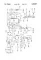
- FIG. 6is a circuit diagram of a power oscillator suitable for use with the ballast lamp structure of the present invention.
- FIG. 7is an isometric view of an electronics assembly constructed for placement within a lamp envelope or for incorporation in a module attachable to the end of the lamp envelope.
- FIG. 8is a partially-sectioned view of a gas discharge lamp with the envelope thereof formed in a U-shaped configuration with the control elements contained within that envelope.
- FIG. 1A conventional fluorescent lamp power distribution system is shown in schematic diagram form in FIG. 1 wherein standard input A.C. power 10 is introduced at the input terminals. In the United States, this input is usually 60 Hz at 110 or 220 volts A.C. This power is introduced in parallel to a plurality of assemblies associated with each of an array of lamp fixtures. These assemblies include a converter, or ballast unit 12A-12N which converts the primary A.C. input to a high frequency, such as 20-30 kilohertz, to drive a set of typically two series connected fluorescent lamps. Thus, ballast unit 12A drives lamps 14A and 15A in series.
- A.C. power 10In the United States, this input is usually 60 Hz at 110 or 220 volts A.C.
- This poweris introduced in parallel to a plurality of assemblies associated with each of an array of lamp fixtures. These assemblies include a converter, or ballast unit 12A-12N which converts the primary A.C. input to a high frequency, such as 20-30 kilohe
- FIGS. 2A and 2BLamp power distribution systems in accordance with this invention are shown in FIGS. 2A and 2B wherein the primary commercially-available power 10 is coupled to either system.
- a stand-alone configurationis shown in FIG. 2A wherein the main power 10 is connected in parallel into a plurality of lamps 11A-11N each of which is self-sufficient in that it contains its own power handling elements preferably including a conducted line noise filter and a power oscillator along the lines of those described later herein.
- FIG. 2Bis likewise driven by a conventional power system at input 10, but includes at least one master power converting unit 20 the output 22 of which is coupled in parallel into a plurality of slave ballast lamps 24A-24N.
- Conventional power factor correction circuitsrequire acceptance of rather large components (frequently bulky capacitors) for bulk energy storage and filtering thereby increasing the volume of the module at the lamp should that module include such circuitry.
- inclusion of the power factor correction in the master unit 20relieves the lamps of that volumetric burden associated with that function.
- Master ballast units 20contain input filters, preferably along with suitable power factor correction circuits, to convert the 60 Hz power internally to a high voltage D.C. while presenting better than 0.99 power factor loading to the A.C. source.
- the major sections of the master ballast 20are shown in sequential block form in FIG. 3.
- the 110/220 VAC input 10is initially passed through surge protection unit 26 where it is also filtered.
- the active power factor of the filtered output from block 26is corrected initially in block section 27 via conventional control circuitry.
- the A.C.is next rectified in block 27 which can include other electronic functions, if desired, such as fault detection.
- Output power switchingis accomplished by a network of output diodes and filters 29 which finally produces the D.C. desired for output bus 22.
- master ballast 20is capable of driving a bank of thirty or more ballast lamps where those lamps include their own oscillator circuit and gas discharge operating components, such as described later herein, for instance.
- master ballast 20receives the input power from a conventional power main 10.
- the primary input power 10is initially passed through circuitry 26 for surge protection and common mode and differential filtering.
- the A.C.is then rectified and appropriate power factor correction reflected back into the primary mains 10 via circuit 27 which likewise drives the control electronics.
- Output diodes and filtersapply the resulting output from circuit block 29 into secondary lamp feed bus 22.
- FIG. 4A block diagram of an embodiment of a ballast lamp 100 is shown in FIG. 4.
- the key to utilizing existing fluorescent lamp design with its 20,000 plus hours of life expectancyis to provide adequate heating power to the cathodes 101 and 102.
- thisis accomplished by routing two thin wires 104 and 105 down the lamp wall to the end heater 102.
- the potential difference between these wiresis developed by the power oscillator 108 in assembly 106 and its associated output transformer 109. After lamp ignition, as in conventional ballasts, this potential is approximately 2.5 volts RMS.
- the power oscillator 108similarly heats the local heater or cathode 101.
- the high voltage starting and running potentialare established as in a conventional ballast across the secondary of the power oscillator output transformer 109.
- the potential difference between local heater 101 and end heater 102is thus 110 VRMs during normal lamp operation. This potential is, however, in the form of a high frequency sine wave with a nearly perfect crest factor (1.414).
- the power oscillator assemblycan take the form of a cylindrical unit 110, containing the hybrid electronics and miniaturized magnetics.
- the lamp shown in FIG. 5is intended for a system wherein the A.C. main power is converted to D.C. power at a remote unit (such as master ballast 20 of FIG. 2B) which is then connected to the lamp.
- a remote unitsuch as master ballast 20 of FIG. 2B
- the two different shaped electrodes 120 and 121are respectively cylindrical and rectangular, and serve to key the lamp during installation so that the correct polarity of the high voltage D.C. is applied.
- a rectangular cross-sectionis acceptable for cylindrical terminal 120, although preferably at 90° to ground terminal 121 to provide an alternate polarity protection scheme.
- the internal electronic oscillatoralso contains reverse polarity protection to prevent tube damage for improperly-wired ballast lamp sockets.
- connection electrodesare not necessary if the module 110 employs a full wave rectifier, such as a diode bridge which can handle any polarity, and protects against polarity reversal. It is acceptable to employ pins similar to a contemporary fluorescent lamp for ease of installation, but preferably with a different pin orientation such as wider or narrower spacings between the pins. This would prevent inadvertent installation of the lamp in a conventional fixture.
- a full wave rectifiersuch as a diode bridge which can handle any polarity, and protects against polarity reversal. It is acceptable to employ pins similar to a contemporary fluorescent lamp for ease of installation, but preferably with a different pin orientation such as wider or narrower spacings between the pins. This would prevent inadvertent installation of the lamp in a conventional fixture.
- the outside shell of the oscillator assembly 110is constructed of a thin sheet of ferrous metal.
- the internal electronicsare mounted to a metal substrate which is attached to the outer shell.
- the metalalso serves as an electromagnetic shield to minimize radiation.
- the shellmay further be attached to the metal structure of lamp fixtures to further increase the heat sink capability of the ballast lamp.
- FIG. 6is a schematic diagram of the power oscillator which is a miniaturized electronic ballast configured to fit inside the fluorescent tube. Most (ninety-five percent or more) of the components are surface mount devices. The exceptions are components, such as the transformer, including primary 130 and secondaries shown at 134 and 135, bulk storage capacitors 131 and 132, inductive coupler 133, and several diodes. Circuit board pins 136 and 137 are connected to the two prongs at one endcap of the fluorescent tube. A.C. power 10, typically 90 to 130 volts RMS, 50 or 60 Hz, is applied to the tube.
- A.C. power 10typically 90 to 130 volts RMS, 50 or 60 Hz
- the far end heater of the tubeis connected via wires passing the length of the tube. While external placement of the end heater wires is acceptable, they are preferably inside the tube and coupled to circuit board pins 143 and 144 of the output transformer secondary 135. The near end heater of the tube is connected to pins 145 and 146.
- the tube socket containing pins 136 and 137 and the power oscillator circuitare one integrated part that is mated with the tube wires at the time of tube assembly either permanently or detachably.
- Transient voltage suppressor (TVS) 140prevents spikes and surges from damaging the electronics.
- Diode bridge 148is an integrated circuit diode bridge for rectifying the input A.C. power.
- Resistor 151 and Zener diode 150are a bootstrap circuit (typically 15 volt) to supply initial power to integrated circuit chip 156.
- Resistors 152 and Zener diode 153likewise provide +5 volt bootstrap power for integrated circuits 156, 157 and 158.
- Capacitors 154 and 155are bulk storage capacitors for these DC supplies.
- Integrated circuit 157is a CMOS 555 timer chip which provides several hundred kilohertz clock signals to integrated circuit chip 158.
- the network of resistors 164 and 165 and capacitor 166set the oscillator frequency while capacitors 167 and 168 are noise decoupling capacitors.
- Clock signals from chip 157are fed to chip 158 which is an HCT74 flip-flop coupled to divide the oscillator clock signals by two to provide a symmetrical square wave signal to integrated circuit 156. While the circuit disclosed was constructed to produce an output signal at transformer 130 with a frequency of 220 kilohertz, it is believed advantageous to design the circuit to function in the megahertz range.
- Integrated circuit ]56is preferably an IR2110S gate driver circuit.
- Power MOS FETS 171 and 172are connected in a half-bridge configuration to drive the primary 130 of the output transformer.
- Capacitor 173is the bootstrap capacitor for chip 156, while diode 162 is the charging diode for capacitor 173.
- Capacitors 174 and 175are decoupling capacitors for chip 156. Networks of resistor 176 and diode 177, as well as resistor 178 and diode 179, prevent cross-conduction of 171 and 172, thereby minimizing power loss and EMI generation. It is possible to realize cross-conduction prevention by including some AND gates between the output of the divider circuit 158 and the driver chip 156. Such gates would logically AND the short pulses from the oscillator circuit 157 with the divider 158 output to prevent cross-conduction at the output FET transistors 171 and 172 which drive the primary of output transformer 130.
- Capacitor 180is the resonant tank capacitor for the output transformer so that while square wave drives appear across primary 130, a quasi-sinusoidal drive is actually applied to the fluorescent tube. After tube ignition, windings 184 of secondary 135 applies approximately 100 volts RMS across the tube, while windings 183 and 185 apply power (such as at 2.7 volts RMS) across the far-and-near end heaters, respectively.
- FIG. 7An exemplary combination of electronic elements adapted for use in conjunction with the envelope of a gas discharge lamp is presented in FIG. 7.
- the planar circuit board 186is shown with through-hole mounted components 187-191 on the upper surface, and surface mounted components 192-195 on the lower surface of board 186.
- Element 187might represent a diode bridge assembly, while 188 and 189 are resistors and 190 and 191 are bulk capacitors or inductor type components.
- the surface mounted elements 192-195might include integrated circuit chips, surface mounted resistors and capacitors or the like.
- Board 186has a receptacle 198 mounted on one end as shown for receiving the pins of array 199 extending from output transformer 200.
- a group of four leads 201extend from transformer 200 to provide the connections to the heater elements, such as 143-146 of FIG. 6, and the heater connections of FIG. 4 for instance.
- Another group of four leads 205couple the primary of the transformer and the secondary winding which functions with the oscillator circuit, such as the FIG. 6 transformer primary 130 and secondary winding 134.
- outer end 196 of board 186preferably would mount within an end cap having dual power connecting prongs for receiving the A.C. or D.C. input power.
- the opposite endcan have any of a variety of known mounting structures as desired. It could include dummy pins similar to contemporary fluorescent lamp bulbs if contemporary fluorescent receptacles elements are employed. Otherwise, a blank endcap and receptacle would suffice for retaining the bulb within a fixture.
- FIG. 8illustrates yet another embodiment of a gas discharge lamp 210 having the elongated envelope 211 constructed preferably with a tubular, or semi-circular, cross-section but in a "U" shape.
- Base 215is secured to envelope 211 as shown with pins 216 and 217 adapted to plug into an A.C. receptacle to provide the primary power source.
- the thus received A.C. poweris connected to a module composed of a board 220 and output transformer 221.
- Board 220has the oscillator circuit and other components and circuitry including the power factor correction circuit mounted thereon for driving the output transformer 221.
- the moduleincluding board 220 and transformer 221, can be encapsulated in a heat transferring material so as to completely fill the end of the envelope 211 in which it is placed. Otherwise, the interior of envelope 211 is filled with a gas discharge medium for producing visible light upon excitation.
- Heater element 222is connected directly to a pair of output connections of transformer 221, while leads 223 pass from transformer 222 through the wall of envelope 211 into the base 215 and thence through the wall of envelope 211 on its opposite end so as to connect with heater element 224. Note that it is possible to suppress undesired radio frequency radiation from the device by shielding, or by ferrite beads on the output leads as is conventional.
Landscapes
- Circuit Arrangements For Discharge Lamps (AREA)
- Lighting Device Outwards From Vehicle And Optical Signal (AREA)
- Lasers (AREA)
- Polyesters Or Polycarbonates (AREA)
- Vessels And Coating Films For Discharge Lamps (AREA)
Abstract
Description
Claims (11)
Priority Applications (9)
| Application Number | Priority Date | Filing Date | Title |
|---|---|---|---|
| US08/116,150US5485057A (en) | 1993-09-02 | 1993-09-02 | Gas discharge lamp and power distribution system therefor |
| PCT/US1994/009955WO1995006951A1 (en) | 1993-09-02 | 1994-09-02 | Gas discharge lamp and power distribution system therefor |
| AT94928556TATE214517T1 (en) | 1993-09-02 | 1994-09-02 | GAS DISCHARGE LAMP AND ENERGY DISTRIBUTION SYSTEM SUITABLE THEREOF |
| DE69430142TDE69430142D1 (en) | 1993-09-02 | 1994-09-02 | GAS DISCHARGE LAMP AND A SUITABLE POWER DISTRIBUTION SYSTEM |
| KR1019960701084AKR100336995B1 (en) | 1993-09-02 | 1994-09-02 | Gas discharge lamp and power distribution system therefor |
| EP94928556AEP0746867B1 (en) | 1993-09-02 | 1994-09-02 | Gas discharge lamp and power distribution system therefor |
| AU77947/94AAU7794794A (en) | 1993-09-02 | 1994-09-02 | Gas discharge lamp and power distribution system therefor |
| CA002169752ACA2169752A1 (en) | 1993-09-02 | 1994-09-02 | Gas discharge lamp and powder distribution system therefor |
| US08/496,623US5654609A (en) | 1993-09-02 | 1995-06-29 | Gas discharge lamp and power distribution system therefor |
Applications Claiming Priority (1)
| Application Number | Priority Date | Filing Date | Title |
|---|---|---|---|
| US08/116,150US5485057A (en) | 1993-09-02 | 1993-09-02 | Gas discharge lamp and power distribution system therefor |
Related Child Applications (1)
| Application Number | Title | Priority Date | Filing Date |
|---|---|---|---|
| US08/496,623ContinuationUS5654609A (en) | 1993-09-02 | 1995-06-29 | Gas discharge lamp and power distribution system therefor |
Publications (1)
| Publication Number | Publication Date |
|---|---|
| US5485057Atrue US5485057A (en) | 1996-01-16 |
Family
ID=22365549
Family Applications (2)
| Application Number | Title | Priority Date | Filing Date |
|---|---|---|---|
| US08/116,150Expired - Fee RelatedUS5485057A (en) | 1993-09-02 | 1993-09-02 | Gas discharge lamp and power distribution system therefor |
| US08/496,623Expired - Fee RelatedUS5654609A (en) | 1993-09-02 | 1995-06-29 | Gas discharge lamp and power distribution system therefor |
Family Applications After (1)
| Application Number | Title | Priority Date | Filing Date |
|---|---|---|---|
| US08/496,623Expired - Fee RelatedUS5654609A (en) | 1993-09-02 | 1995-06-29 | Gas discharge lamp and power distribution system therefor |
Country Status (8)
| Country | Link |
|---|---|
| US (2) | US5485057A (en) |
| EP (1) | EP0746867B1 (en) |
| KR (1) | KR100336995B1 (en) |
| AT (1) | ATE214517T1 (en) |
| AU (1) | AU7794794A (en) |
| CA (1) | CA2169752A1 (en) |
| DE (1) | DE69430142D1 (en) |
| WO (1) | WO1995006951A1 (en) |
Cited By (47)
| Publication number | Priority date | Publication date | Assignee | Title |
|---|---|---|---|---|
| US5654609A (en)* | 1993-09-02 | 1997-08-05 | Logic Laboratories, Inc. | Gas discharge lamp and power distribution system therefor |
| US5703442A (en)* | 1996-04-29 | 1997-12-30 | Electronic Lighting Incorporated | Method and apparatus for interfacing a light dimming control with an automated control system |
| US5747942A (en)* | 1996-07-10 | 1998-05-05 | Enersol Systems, Inc. | Inverter for an electronic ballast having independent start-up and operational output voltages |
| US6244724B1 (en)* | 1997-01-20 | 2001-06-12 | Patent-Treuhand-Gesellschaft Fuer Elektrische Gluehlampen Mbh | Electric luminaire for discharge lamp having insulation-piercing contacts |
| US6320329B1 (en) | 1999-07-30 | 2001-11-20 | Philips Electronics North America Corporation | Modular high frequency ballast architecture |
| WO2001093379A1 (en)* | 2000-05-30 | 2001-12-06 | Lempi @ S.A. | Switching power supply for discharge lamp and method for powering a lamp |
| US6376991B1 (en) | 2001-01-10 | 2002-04-23 | Philips Electronics North America Corporation | Circuit assembly for inclusion within fluorescent lamp |
| US6443769B1 (en) | 2001-02-15 | 2002-09-03 | General Electric Company | Lamp electronic end cap for integral lamp |
| US6459215B1 (en) | 2000-08-11 | 2002-10-01 | General Electric Company | Integral lamp |
| US6552491B1 (en) | 2000-12-13 | 2003-04-22 | Koninklijke Philips Electronics N.V. | Fluorescent lamp with integral circuitry |
| US6555974B1 (en) | 2000-11-21 | 2003-04-29 | General Electric Company | Wiring geometry for multiple integral lamps |
| US20030184242A1 (en)* | 1999-06-08 | 2003-10-02 | Alain Denes | Switching power supply for discharge lamp and method for powering a lamp |
| US20040076001A1 (en)* | 2002-10-17 | 2004-04-22 | Lutes Arthur L. | Leadless ballast |
| US6731076B1 (en)* | 1999-03-26 | 2004-05-04 | Vogt Electronic Ag | Base of an electric discharge lamp with an ignition device |
| US20040109317A1 (en)* | 2002-10-04 | 2004-06-10 | Ribarich Thomas J. | Compact fluorescent lamp package |
| US6814462B1 (en)* | 2000-08-29 | 2004-11-09 | Ole K. Nilssen | Under-cabinet lighting system |
| US20050035730A1 (en)* | 2003-08-14 | 2005-02-17 | Sluggo Lighting Ltd. | Distributed fluorescent light control system |
| US20050062436A1 (en)* | 2003-09-09 | 2005-03-24 | Xiaoping Jin | Split phase inverters for CCFL backlight system |
| US20050093484A1 (en)* | 2003-10-21 | 2005-05-05 | Ball Newton E. | Systems and methods for fault protection in a balancing transformer |
| US20050093471A1 (en)* | 2003-10-06 | 2005-05-05 | Xiaoping Jin | Current sharing scheme for multiple CCF lamp operation |
| EP1555860A1 (en)* | 2004-01-14 | 2005-07-20 | TridonicAtco GmbH & Co. KG | DC-fed driving modules for light sources |
| US20050156540A1 (en)* | 2003-12-16 | 2005-07-21 | Ball Newton E. | Inverter with two switching stages for driving lamp |
| US20050190142A1 (en)* | 2004-02-09 | 2005-09-01 | Ferguson Bruce R. | Method and apparatus to control display brightness with ambient light correction |
| US20050218839A1 (en)* | 2002-10-04 | 2005-10-06 | International Rectifier Corporation | Dimmable fluorescent lamp package |
| US20050225261A1 (en)* | 2004-04-07 | 2005-10-13 | Xiaoping Jin | Primary side current balancing scheme for multiple CCF lamp operation |
| US20060077659A1 (en)* | 1998-11-27 | 2006-04-13 | Seiichi Nishiyama | Liquid crystal display |
| US7061183B1 (en) | 2005-03-31 | 2006-06-13 | Microsemi Corporation | Zigzag topology for balancing current among paralleled gas discharge lamps |
| US20060220593A1 (en)* | 2005-03-31 | 2006-10-05 | Ball Newton E | Nested balancing topology for balancing current among multiple lamps |
| US20060256589A1 (en)* | 2005-05-13 | 2006-11-16 | Hwangsoo Choi | Shoot-through prevention circuit for passive level-shifter |
| US20060273738A1 (en)* | 2005-06-06 | 2006-12-07 | Holst Barrie J | Cold cathode fluorescent lamp |
| US20070014130A1 (en)* | 2004-04-01 | 2007-01-18 | Chii-Fa Chiou | Full-bridge and half-bridge compatible driver timing schedule for direct drive backlight system |
| US20070132398A1 (en)* | 2003-09-23 | 2007-06-14 | Microsemi Corporation | Optical and temperature feedbacks to control display brightness |
| USD555110S1 (en)* | 2004-01-16 | 2007-11-13 | Fanglu Lou | Electronic controller for a gas discharge lamp |
| US20080024075A1 (en)* | 2002-12-13 | 2008-01-31 | Microsemi Corporation | Apparatus and method for striking a fluorescent lamp |
| US20080055814A1 (en)* | 2006-08-31 | 2008-03-06 | Viktor Karoly Varga | Lamp transformer |
| US20080055879A1 (en)* | 2006-08-31 | 2008-03-06 | Varga Viktor K | Lamp transformer |
| KR100846684B1 (en)* | 2000-08-16 | 2008-07-16 | 지멘스 악티엔게젤샤프트 | Luminaires with at least one U-shaped gas discharge lamp |
| US7414371B1 (en) | 2005-11-21 | 2008-08-19 | Microsemi Corporation | Voltage regulation loop with variable gain control for inverter circuit |
| US7569998B2 (en) | 2006-07-06 | 2009-08-04 | Microsemi Corporation | Striking and open lamp regulation for CCFL controller |
| US20090230896A1 (en)* | 2008-03-17 | 2009-09-17 | Yung-Chuan Lin | Fluorescent Lamp Holder Combination Device |
| US20100123400A1 (en)* | 2008-11-20 | 2010-05-20 | Microsemi Corporation | Method and apparatus for driving ccfl at low burst duty cycle rates |
| US7755595B2 (en) | 2004-06-07 | 2010-07-13 | Microsemi Corporation | Dual-slope brightness control for transflective displays |
| US7977888B2 (en) | 2003-10-06 | 2011-07-12 | Microsemi Corporation | Direct coupled balancer drive for floating lamp structure |
| CN101287319B (en)* | 2008-06-13 | 2013-03-20 | 许观泉 | Energy-saving florescent lamp |
| US8598795B2 (en) | 2011-05-03 | 2013-12-03 | Microsemi Corporation | High efficiency LED driving method |
| US8754581B2 (en) | 2011-05-03 | 2014-06-17 | Microsemi Corporation | High efficiency LED driving method for odd number of LED strings |
| US9030119B2 (en) | 2010-07-19 | 2015-05-12 | Microsemi Corporation | LED string driver arrangement with non-dissipative current balancer |
Families Citing this family (16)
| Publication number | Priority date | Publication date | Assignee | Title |
|---|---|---|---|---|
| FR2804571B1 (en)* | 2000-01-27 | 2004-07-23 | Eclairage Public Beep Bureau E | MODULE FORMING A BOOSTER-INVERTER FOR A DEVICE FOR SUPPLYING A DISCHARGE LAMP AND METHOD FOR MOUNTING A FLOOR LAMP OR PROJECTOR COMPRISING SUCH A MODULE |
| FR2804570B1 (en) | 2000-01-27 | 2002-07-19 | Eclairage Public Beep Bureau E | MODULAR ELECTRONIC SUPPLY DEVICE FOR DISCHARGE LAMP |
| FR2804572B1 (en)* | 2000-02-01 | 2002-04-19 | Dev Ind Et Commercial D Aldim | MEDIUM FREQUENCY GENERATOR DEVICE FOR POWERING A DISCHARGE LAMP |
| JP3975653B2 (en)* | 2000-06-12 | 2007-09-12 | 松下電工株式会社 | Discharge lamp lighting device |
| IT1316561B1 (en)* | 2000-12-28 | 2003-04-22 | Setech S R L | FEEDING DEVICE FOR COLD CATHODE LAMPS. |
| EP1244337A1 (en)* | 2001-03-20 | 2002-09-25 | MAGNETEK S.p.A. | Lighting system with an electrified line and a plurality of lighting fixtures connected to it |
| DE10163957A1 (en)* | 2001-12-23 | 2003-07-03 | Der Kluth Decke Und Licht Gmbh | Electronic voltage adapter for light sources is able to be connected to more than two light sources, especially fluorescent tubes, has rectifier connected to several high frequency generators |
| US20040232775A1 (en)* | 2003-05-19 | 2004-11-25 | Nilssen Ole K. | Lighting system comprised of a unique direct current power supply and a plurality of gas discharge luminaires |
| DE102004002017B4 (en)* | 2004-01-14 | 2019-12-12 | Tridonic Gmbh & Co Kg | Control of control gear for lamps using switching modulation of a DC bus |
| DE102004058881A1 (en)* | 2004-12-06 | 2006-06-08 | Patent-Treuhand-Gesellschaft für elektrische Glühlampen mbH | High pressure discharge lamp and lighting device with high pressure discharge lamp |
| US20070076386A1 (en)* | 2005-08-22 | 2007-04-05 | Thin-Lite Corporation | Optimized light fixture circuit board |
| US20070109795A1 (en)* | 2005-11-15 | 2007-05-17 | Gabrius Algimantas J | Thermal dissipation system |
| US20080169768A1 (en)* | 2007-01-16 | 2008-07-17 | Kevin Yang | Electronic ballast with PCB edge mounted output transformer/inductor |
| US20090289553A1 (en)* | 2008-05-23 | 2009-11-26 | Osram Sylvania, Inc. | Integrated ceramic metal halide high frequency ballast assembly |
| ITCZ20090016A1 (en)* | 2009-08-27 | 2011-02-28 | Edp Srl | DIMMABLE ELECTRONIC FEEDER ABLE TO CHECK CONTINUOUSLY THE POWER SUPPLIED TO A GAS DISCHARGE LAMP AND POWER CONTROL METHOD. |
| US8454207B2 (en)* | 2010-06-03 | 2013-06-04 | General Electric Company | Multi-lamp fluorescent lighting fixture apparatus and wiring method |
Citations (15)
| Publication number | Priority date | Publication date | Assignee | Title |
|---|---|---|---|---|
| US3549941A (en)* | 1968-06-03 | 1970-12-22 | Arnold Friedmann | Discharge lamp with circuit elements incorporated in the envelope |
| US3753071A (en)* | 1972-06-15 | 1973-08-14 | Westinghouse Electric Corp | Low cost transistorized inverter |
| GB1401628A (en)* | 1971-11-18 | 1975-07-16 | Victor Products Ltd | Electric power supply systems |
| US4109307A (en)* | 1977-05-04 | 1978-08-22 | Gte Sylvania Incorporated | High power factor conversion circuitry |
| US4259614A (en)* | 1979-07-20 | 1981-03-31 | Kohler Thomas P | Electronic ballast-inverter for multiple fluorescent lamps |
| US4293799A (en)* | 1979-10-05 | 1981-10-06 | Victor Products (Wallsend) Limited | Power supply systems |
| US4316121A (en)* | 1979-11-01 | 1982-02-16 | General Electric Company | Integrally ballasted fluorescent lamp unit |
| US4508996A (en)* | 1980-06-23 | 1985-04-02 | Brigham Young University | High frequency supply system for gas discharge lamps and electronic ballast therefor |
| US4571526A (en)* | 1980-09-11 | 1986-02-18 | U.S. Philips Corporation | Low-pressure discharge lamp with cooled internal ballast |
| US4857806A (en)* | 1980-08-14 | 1989-08-15 | Nilssen Ole K | Self-ballasted screw-in fluorescent lamp |
| US4939420A (en)* | 1987-04-06 | 1990-07-03 | Lim Kenneth S | Fluorescent reflector lamp assembly |
| US5047696A (en)* | 1982-12-16 | 1991-09-10 | Nilssen Ole K | Power-limited ceiling lighting system |
| US5189339A (en)* | 1990-09-05 | 1993-02-23 | Applied Lumens, Ltd. | Fluorescent lamp assemblies |
| US5208511A (en)* | 1991-03-21 | 1993-05-04 | North American Philips Corporation | Fluorescent lamp electrode disconnect arrangement |
| US5294865A (en)* | 1992-09-18 | 1994-03-15 | Gte Products Corporation | Lamp with integrated electronic module |
Family Cites Families (4)
| Publication number | Priority date | Publication date | Assignee | Title |
|---|---|---|---|---|
| GB2072958B (en)* | 1979-09-06 | 1983-09-01 | English Electric Valve Co Ltd | Lamps |
| SE8500648D0 (en)* | 1985-02-12 | 1985-02-12 | Lumalampan Ab | DEVICE ON LIGHTS |
| FR2632774B1 (en)* | 1988-06-13 | 1990-10-05 | Muessli Daniel | DISCHARGE LAMP COMPRISING A STANDARD BASE |
| US5485057A (en)* | 1993-09-02 | 1996-01-16 | Smallwood; Robert C. | Gas discharge lamp and power distribution system therefor |
- 1993
- 1993-09-02USUS08/116,150patent/US5485057A/ennot_activeExpired - Fee Related
- 1994
- 1994-09-02AUAU77947/94Apatent/AU7794794A/ennot_activeAbandoned
- 1994-09-02KRKR1019960701084Apatent/KR100336995B1/ennot_activeExpired - Fee Related
- 1994-09-02WOPCT/US1994/009955patent/WO1995006951A1/enactiveIP Right Grant
- 1994-09-02EPEP94928556Apatent/EP0746867B1/ennot_activeExpired - Lifetime
- 1994-09-02DEDE69430142Tpatent/DE69430142D1/ennot_activeExpired - Lifetime
- 1994-09-02CACA002169752Apatent/CA2169752A1/ennot_activeAbandoned
- 1994-09-02ATAT94928556Tpatent/ATE214517T1/ennot_activeIP Right Cessation
- 1995
- 1995-06-29USUS08/496,623patent/US5654609A/ennot_activeExpired - Fee Related
Patent Citations (15)
| Publication number | Priority date | Publication date | Assignee | Title |
|---|---|---|---|---|
| US3549941A (en)* | 1968-06-03 | 1970-12-22 | Arnold Friedmann | Discharge lamp with circuit elements incorporated in the envelope |
| GB1401628A (en)* | 1971-11-18 | 1975-07-16 | Victor Products Ltd | Electric power supply systems |
| US3753071A (en)* | 1972-06-15 | 1973-08-14 | Westinghouse Electric Corp | Low cost transistorized inverter |
| US4109307A (en)* | 1977-05-04 | 1978-08-22 | Gte Sylvania Incorporated | High power factor conversion circuitry |
| US4259614A (en)* | 1979-07-20 | 1981-03-31 | Kohler Thomas P | Electronic ballast-inverter for multiple fluorescent lamps |
| US4293799A (en)* | 1979-10-05 | 1981-10-06 | Victor Products (Wallsend) Limited | Power supply systems |
| US4316121A (en)* | 1979-11-01 | 1982-02-16 | General Electric Company | Integrally ballasted fluorescent lamp unit |
| US4508996A (en)* | 1980-06-23 | 1985-04-02 | Brigham Young University | High frequency supply system for gas discharge lamps and electronic ballast therefor |
| US4857806A (en)* | 1980-08-14 | 1989-08-15 | Nilssen Ole K | Self-ballasted screw-in fluorescent lamp |
| US4571526A (en)* | 1980-09-11 | 1986-02-18 | U.S. Philips Corporation | Low-pressure discharge lamp with cooled internal ballast |
| US5047696A (en)* | 1982-12-16 | 1991-09-10 | Nilssen Ole K | Power-limited ceiling lighting system |
| US4939420A (en)* | 1987-04-06 | 1990-07-03 | Lim Kenneth S | Fluorescent reflector lamp assembly |
| US5189339A (en)* | 1990-09-05 | 1993-02-23 | Applied Lumens, Ltd. | Fluorescent lamp assemblies |
| US5208511A (en)* | 1991-03-21 | 1993-05-04 | North American Philips Corporation | Fluorescent lamp electrode disconnect arrangement |
| US5294865A (en)* | 1992-09-18 | 1994-03-15 | Gte Products Corporation | Lamp with integrated electronic module |
Non-Patent Citations (2)
| Title |
|---|
| International Application PCT/US91/02895, "Electronic Lamp Ballast for Gas Discharge Lamp" by Smallwood, WO 91/16802. |
| International Application PCT/US91/02895, Electronic Lamp Ballast for Gas Discharge Lamp by Smallwood, WO 91/16802.* |
Cited By (102)
| Publication number | Priority date | Publication date | Assignee | Title |
|---|---|---|---|---|
| US5654609A (en)* | 1993-09-02 | 1997-08-05 | Logic Laboratories, Inc. | Gas discharge lamp and power distribution system therefor |
| US5703442A (en)* | 1996-04-29 | 1997-12-30 | Electronic Lighting Incorporated | Method and apparatus for interfacing a light dimming control with an automated control system |
| US5747942A (en)* | 1996-07-10 | 1998-05-05 | Enersol Systems, Inc. | Inverter for an electronic ballast having independent start-up and operational output voltages |
| US6244724B1 (en)* | 1997-01-20 | 2001-06-12 | Patent-Treuhand-Gesellschaft Fuer Elektrische Gluehlampen Mbh | Electric luminaire for discharge lamp having insulation-piercing contacts |
| US7283194B2 (en) | 1998-11-27 | 2007-10-16 | Hitachi, Ltd. | Liquid crystal display |
| US7077543B2 (en)* | 1998-11-27 | 2006-07-18 | Hitachi, Ltd. | Liquid crystal display |
| US20060077659A1 (en)* | 1998-11-27 | 2006-04-13 | Seiichi Nishiyama | Liquid crystal display |
| US7473021B2 (en) | 1998-11-27 | 2009-01-06 | Hitachi, Ltd. | Liquid crystal display |
| US20060268192A1 (en)* | 1998-11-27 | 2006-11-30 | Seiichi Nishiyama | Liquid crystal display |
| US6731076B1 (en)* | 1999-03-26 | 2004-05-04 | Vogt Electronic Ag | Base of an electric discharge lamp with an ignition device |
| US20030184242A1 (en)* | 1999-06-08 | 2003-10-02 | Alain Denes | Switching power supply for discharge lamp and method for powering a lamp |
| US6888320B2 (en) | 1999-06-08 | 2005-05-03 | Lempi Sa | Switching power supply for discharge lamp and method for powering a lamp |
| US6320329B1 (en) | 1999-07-30 | 2001-11-20 | Philips Electronics North America Corporation | Modular high frequency ballast architecture |
| WO2001093379A1 (en)* | 2000-05-30 | 2001-12-06 | Lempi @ S.A. | Switching power supply for discharge lamp and method for powering a lamp |
| US20030006718A1 (en)* | 2000-08-11 | 2003-01-09 | Nerone Louis R. | Integral lamp |
| US6459215B1 (en) | 2000-08-11 | 2002-10-01 | General Electric Company | Integral lamp |
| US7102298B2 (en) | 2000-08-11 | 2006-09-05 | General Electric Company | Integral lamp |
| KR100846684B1 (en)* | 2000-08-16 | 2008-07-16 | 지멘스 악티엔게젤샤프트 | Luminaires with at least one U-shaped gas discharge lamp |
| US6814462B1 (en)* | 2000-08-29 | 2004-11-09 | Ole K. Nilssen | Under-cabinet lighting system |
| US6555974B1 (en) | 2000-11-21 | 2003-04-29 | General Electric Company | Wiring geometry for multiple integral lamps |
| US6552491B1 (en) | 2000-12-13 | 2003-04-22 | Koninklijke Philips Electronics N.V. | Fluorescent lamp with integral circuitry |
| US6376991B1 (en) | 2001-01-10 | 2002-04-23 | Philips Electronics North America Corporation | Circuit assembly for inclusion within fluorescent lamp |
| US6443769B1 (en) | 2001-02-15 | 2002-09-03 | General Electric Company | Lamp electronic end cap for integral lamp |
| US20040109317A1 (en)* | 2002-10-04 | 2004-06-10 | Ribarich Thomas J. | Compact fluorescent lamp package |
| US20070188103A1 (en)* | 2002-10-04 | 2007-08-16 | International Rectifier Corporation | Dimmable fluorescent lamp package |
| US20050218839A1 (en)* | 2002-10-04 | 2005-10-06 | International Rectifier Corporation | Dimmable fluorescent lamp package |
| US7753558B2 (en) | 2002-10-04 | 2010-07-13 | International Rectifier Corporation | Compact fluorescent lamp package |
| US7224125B2 (en) | 2002-10-04 | 2007-05-29 | International Rectifier Corporation | Dimmable fluorescent lamp package |
| US7633230B2 (en) | 2002-10-04 | 2009-12-15 | International Rectifier Corporation | Dimmable fluorescent lamp package |
| US20040076001A1 (en)* | 2002-10-17 | 2004-04-22 | Lutes Arthur L. | Leadless ballast |
| US7411360B2 (en) | 2002-12-13 | 2008-08-12 | Microsemi Corporation | Apparatus and method for striking a fluorescent lamp |
| US20080024075A1 (en)* | 2002-12-13 | 2008-01-31 | Microsemi Corporation | Apparatus and method for striking a fluorescent lamp |
| US7161312B2 (en)* | 2003-08-14 | 2007-01-09 | Sluggo Lighting Ltd. | Distributed fluorescent light control system |
| US20050035730A1 (en)* | 2003-08-14 | 2005-02-17 | Sluggo Lighting Ltd. | Distributed fluorescent light control system |
| US20090206767A1 (en)* | 2003-09-09 | 2009-08-20 | Microsemi Corporation | Split phase inverters for ccfl backlight system |
| US7952298B2 (en) | 2003-09-09 | 2011-05-31 | Microsemi Corporation | Split phase inverters for CCFL backlight system |
| US7187139B2 (en) | 2003-09-09 | 2007-03-06 | Microsemi Corporation | Split phase inverters for CCFL backlight system |
| US7525255B2 (en) | 2003-09-09 | 2009-04-28 | Microsemi Corporation | Split phase inverters for CCFL backlight system |
| US20070145911A1 (en)* | 2003-09-09 | 2007-06-28 | Microsemi Corporation | Split phase inverters for ccfl backlight system |
| US20050062436A1 (en)* | 2003-09-09 | 2005-03-24 | Xiaoping Jin | Split phase inverters for CCFL backlight system |
| US7391172B2 (en) | 2003-09-23 | 2008-06-24 | Microsemi Corporation | Optical and temperature feedbacks to control display brightness |
| US20070132398A1 (en)* | 2003-09-23 | 2007-06-14 | Microsemi Corporation | Optical and temperature feedbacks to control display brightness |
| US7990072B2 (en) | 2003-10-06 | 2011-08-02 | Microsemi Corporation | Balancing arrangement with reduced amount of balancing transformers |
| US8222836B2 (en) | 2003-10-06 | 2012-07-17 | Microsemi Corporation | Balancing transformers for multi-lamp operation |
| US20090267521A1 (en)* | 2003-10-06 | 2009-10-29 | Microsemi Corporation | Balancing transformers for multi-lamp operation |
| US7294971B2 (en) | 2003-10-06 | 2007-11-13 | Microsemi Corporation | Balancing transformers for ring balancer |
| US7932683B2 (en) | 2003-10-06 | 2011-04-26 | Microsemi Corporation | Balancing transformers for multi-lamp operation |
| US7977888B2 (en) | 2003-10-06 | 2011-07-12 | Microsemi Corporation | Direct coupled balancer drive for floating lamp structure |
| US20110181204A1 (en)* | 2003-10-06 | 2011-07-28 | Microsemi Corporation | Balancing transformers for multi-lamp operation |
| US8008867B2 (en) | 2003-10-06 | 2011-08-30 | Microsemi Corporation | Arrangement suitable for driving floating CCFL based backlight |
| US7242147B2 (en) | 2003-10-06 | 2007-07-10 | Microsemi Corporation | Current sharing scheme for multiple CCF lamp operation |
| US7560875B2 (en) | 2003-10-06 | 2009-07-14 | Microsemi Corporation | Balancing transformers for multi-lamp operation |
| US20050093471A1 (en)* | 2003-10-06 | 2005-05-05 | Xiaoping Jin | Current sharing scheme for multiple CCF lamp operation |
| US20050093472A1 (en)* | 2003-10-06 | 2005-05-05 | Xiaoping Jin | Balancing transformers for ring balancer |
| US20050093483A1 (en)* | 2003-10-21 | 2005-05-05 | Ball Newton E. | Systems and methods for a transformer configuration for driving multiple gas discharge tubes in parallel |
| US7279851B2 (en) | 2003-10-21 | 2007-10-09 | Microsemi Corporation | Systems and methods for fault protection in a balancing transformer |
| US7250726B2 (en) | 2003-10-21 | 2007-07-31 | Microsemi Corporation | Systems and methods for a transformer configuration with a tree topology for current balancing in gas discharge lamps |
| US20050093484A1 (en)* | 2003-10-21 | 2005-05-05 | Ball Newton E. | Systems and methods for fault protection in a balancing transformer |
| US7141933B2 (en) | 2003-10-21 | 2006-11-28 | Microsemi Corporation | Systems and methods for a transformer configuration for driving multiple gas discharge tubes in parallel |
| US20050156539A1 (en)* | 2003-12-16 | 2005-07-21 | Ball Newton E. | Lamp current control using profile synthesizer |
| US7239087B2 (en) | 2003-12-16 | 2007-07-03 | Microsemi Corporation | Method and apparatus to drive LED arrays using time sharing technique |
| US20050156540A1 (en)* | 2003-12-16 | 2005-07-21 | Ball Newton E. | Inverter with two switching stages for driving lamp |
| US7265499B2 (en) | 2003-12-16 | 2007-09-04 | Microsemi Corporation | Current-mode direct-drive inverter |
| US20050162098A1 (en)* | 2003-12-16 | 2005-07-28 | Ball Newton E. | Current-mode direct-drive inverter |
| US7183724B2 (en) | 2003-12-16 | 2007-02-27 | Microsemi Corporation | Inverter with two switching stages for driving lamp |
| US7187140B2 (en) | 2003-12-16 | 2007-03-06 | Microsemi Corporation | Lamp current control using profile synthesizer |
| EP1555860A1 (en)* | 2004-01-14 | 2005-07-20 | TridonicAtco GmbH & Co. KG | DC-fed driving modules for light sources |
| EP1947913A1 (en)* | 2004-01-14 | 2008-07-23 | TridonicAtco GmbH & Co. KG | DC supplied operating module for illuminant |
| USD555110S1 (en)* | 2004-01-16 | 2007-11-13 | Fanglu Lou | Electronic controller for a gas discharge lamp |
| US20050190142A1 (en)* | 2004-02-09 | 2005-09-01 | Ferguson Bruce R. | Method and apparatus to control display brightness with ambient light correction |
| US8223117B2 (en) | 2004-02-09 | 2012-07-17 | Microsemi Corporation | Method and apparatus to control display brightness with ambient light correction |
| US7468722B2 (en) | 2004-02-09 | 2008-12-23 | Microsemi Corporation | Method and apparatus to control display brightness with ambient light correction |
| US7646152B2 (en) | 2004-04-01 | 2010-01-12 | Microsemi Corporation | Full-bridge and half-bridge compatible driver timing schedule for direct drive backlight system |
| US20070014130A1 (en)* | 2004-04-01 | 2007-01-18 | Chii-Fa Chiou | Full-bridge and half-bridge compatible driver timing schedule for direct drive backlight system |
| US20100090611A1 (en)* | 2004-04-01 | 2010-04-15 | Microsemi Corporation | Full-bridge and half-bridge compatible driver timing schedule for direct drive backlight system |
| US7965046B2 (en) | 2004-04-01 | 2011-06-21 | Microsemi Corporation | Full-bridge and half-bridge compatible driver timing schedule for direct drive backlight system |
| US7250731B2 (en) | 2004-04-07 | 2007-07-31 | Microsemi Corporation | Primary side current balancing scheme for multiple CCF lamp operation |
| US20050225261A1 (en)* | 2004-04-07 | 2005-10-13 | Xiaoping Jin | Primary side current balancing scheme for multiple CCF lamp operation |
| US7557517B2 (en) | 2004-04-07 | 2009-07-07 | Microsemi Corporation | Primary side current balancing scheme for multiple CCF lamp operation |
| US7755595B2 (en) | 2004-06-07 | 2010-07-13 | Microsemi Corporation | Dual-slope brightness control for transflective displays |
| US7173382B2 (en) | 2005-03-31 | 2007-02-06 | Microsemi Corporation | Nested balancing topology for balancing current among multiple lamps |
| US20060220593A1 (en)* | 2005-03-31 | 2006-10-05 | Ball Newton E | Nested balancing topology for balancing current among multiple lamps |
| US7061183B1 (en) | 2005-03-31 | 2006-06-13 | Microsemi Corporation | Zigzag topology for balancing current among paralleled gas discharge lamps |
| US7313006B2 (en) | 2005-05-13 | 2007-12-25 | Microsemi Corporation | Shoot-through prevention circuit for passive level-shifter |
| US20060256589A1 (en)* | 2005-05-13 | 2006-11-16 | Hwangsoo Choi | Shoot-through prevention circuit for passive level-shifter |
| US20060273738A1 (en)* | 2005-06-06 | 2006-12-07 | Holst Barrie J | Cold cathode fluorescent lamp |
| US7414371B1 (en) | 2005-11-21 | 2008-08-19 | Microsemi Corporation | Voltage regulation loop with variable gain control for inverter circuit |
| US8358082B2 (en) | 2006-07-06 | 2013-01-22 | Microsemi Corporation | Striking and open lamp regulation for CCFL controller |
| US20090273295A1 (en)* | 2006-07-06 | 2009-11-05 | Microsemi Corporation | Striking and open lamp regulation for ccfl controller |
| US7569998B2 (en) | 2006-07-06 | 2009-08-04 | Microsemi Corporation | Striking and open lamp regulation for CCFL controller |
| US20080055814A1 (en)* | 2006-08-31 | 2008-03-06 | Viktor Karoly Varga | Lamp transformer |
| US7760061B2 (en) | 2006-08-31 | 2010-07-20 | General Electric Company | Lamp transformer |
| US7855625B2 (en) | 2006-08-31 | 2010-12-21 | General Electric Company | Lamp transformer |
| US20080055879A1 (en)* | 2006-08-31 | 2008-03-06 | Varga Viktor K | Lamp transformer |
| US20090230896A1 (en)* | 2008-03-17 | 2009-09-17 | Yung-Chuan Lin | Fluorescent Lamp Holder Combination Device |
| CN101287319B (en)* | 2008-06-13 | 2013-03-20 | 许观泉 | Energy-saving florescent lamp |
| US8093839B2 (en) | 2008-11-20 | 2012-01-10 | Microsemi Corporation | Method and apparatus for driving CCFL at low burst duty cycle rates |
| US20100123400A1 (en)* | 2008-11-20 | 2010-05-20 | Microsemi Corporation | Method and apparatus for driving ccfl at low burst duty cycle rates |
| US9030119B2 (en) | 2010-07-19 | 2015-05-12 | Microsemi Corporation | LED string driver arrangement with non-dissipative current balancer |
| US8598795B2 (en) | 2011-05-03 | 2013-12-03 | Microsemi Corporation | High efficiency LED driving method |
| US8754581B2 (en) | 2011-05-03 | 2014-06-17 | Microsemi Corporation | High efficiency LED driving method for odd number of LED strings |
| USRE46502E1 (en) | 2011-05-03 | 2017-08-01 | Microsemi Corporation | High efficiency LED driving method |
Also Published As
| Publication number | Publication date |
|---|---|
| AU7794794A (en) | 1995-03-22 |
| EP0746867A4 (en) | 1998-01-28 |
| US5654609A (en) | 1997-08-05 |
| CA2169752A1 (en) | 1995-03-09 |
| EP0746867B1 (en) | 2002-03-13 |
| ATE214517T1 (en) | 2002-03-15 |
| DE69430142D1 (en) | 2002-04-18 |
| KR100336995B1 (en) | 2002-11-22 |
| WO1995006951A1 (en) | 1995-03-09 |
| EP0746867A1 (en) | 1996-12-11 |
Similar Documents
| Publication | Publication Date | Title |
|---|---|---|
| US5485057A (en) | Gas discharge lamp and power distribution system therefor | |
| US5691603A (en) | Electronic ballast with multiple lamp loads | |
| US5309062A (en) | Three-way compact fluorescent lamp system utilizing an electronic ballast having a variable frequency oscillator | |
| US8686655B2 (en) | Lighting circuit, lamp, and illumination apparatus | |
| US5751120A (en) | DC operated electronic ballast for fluorescent light | |
| CN101555999B (en) | Inductively powered lamp assembly | |
| EP0951730B1 (en) | Illumination unit and liquid crystal display device | |
| US4950959A (en) | Cassette light, powering unit therefore, multi-dynamic smart magnetic structure and method | |
| WO1994027419A1 (en) | System and method for distributing power to gas discharge lamps | |
| EP0150536B1 (en) | Ballast adaptor for improving operation of fluorescent lamps | |
| US6144445A (en) | Electronic ballast products and systems | |
| EP1352413A1 (en) | Circuit assembly for inclusion within fluorescent lamp | |
| US20050104537A1 (en) | High frequency electronic ballast with sine wave oscillator | |
| JP5383077B2 (en) | Ballast for powering a lamp load having at least one gas discharge lamp | |
| EP0581912B1 (en) | Improved low loss ballast system | |
| US4634932A (en) | Lighting system | |
| US6555971B1 (en) | High frequency, high efficiency quick restart lighting system | |
| WO1992001334A1 (en) | Magnetic structure and power converter for light sources | |
| US4388564A (en) | Energy saving fluorescent lamp circuit | |
| US4701673A (en) | Ballast adaptor for improving operation of fluorescent lamps | |
| US20040232775A1 (en) | Lighting system comprised of a unique direct current power supply and a plurality of gas discharge luminaires | |
| WO2002060227A2 (en) | Wiring geometry for multiple integral lamps | |
| US4467247A (en) | High frequency fluorescent lamp circuit | |
| RU2239961C2 (en) | Apparatus for energy-saving operation of fluorescent lamp and contact device for connecting this apparatus to lamp | |
| US20050012463A1 (en) | One-to-many compact fluorescent lamp holder structure |
Legal Events
| Date | Code | Title | Description |
|---|---|---|---|
| AS | Assignment | Owner name:AMERICAN COMPACT LIGHTING LLC, VIRGINIA Free format text:ASSIGNMENT OF ASSIGNORS INTEREST;ASSIGNOR:ZARICH, MICHAEL P.;REEL/FRAME:007358/0593 Effective date:19950201 | |
| AS | Assignment | Owner name:SMALLWOOD, ROBERT C., VIRGINIA Free format text:ASSIGNMENT OF ASSIGNORS INTEREST;ASSIGNOR:LOGIC LABORATORIES, INC.;REEL/FRAME:007919/0836 Effective date:19960503 | |
| AS | Assignment | Owner name:LOGIC LABORATORIES, INC., VIRGINIA Free format text:ASSIGNMENT OF ASSIGNORS INTEREST;ASSIGNOR:AMERICAN COMPACT LIGHTING, L.L.C.;REEL/FRAME:007927/0139 Effective date:19960125 | |
| AS | Assignment | Owner name:LOGIC LABORATORIES, INC., VIRGINIA Free format text:ASSIGNMENT OF ASSIGNORS INTEREST;ASSIGNOR:SMALLWOOD, ROBERT C.;REEL/FRAME:008104/0123 Effective date:19960826 | |
| AS | Assignment | Owner name:SMALLWOOD,CONSTANCE ELAINE, VIRGINIA Free format text:SECURITY INTEREST;ASSIGNOR:LOGIC LABORATORIES, INC. T/A LOGIC LABS;REEL/FRAME:008251/0496 Effective date:19961227 | |
| AS | Assignment | Owner name:SMALLWOOD, ROBERT C., VIRGINIA Free format text:SECURITY AGREEMENT;ASSIGNOR:LOGIC LABORATORIES, INC., T/A LOGIC LABS;REEL/FRAME:008251/0506 Effective date:19961227 | |
| AS | Assignment | Owner name:LOGIC LABORATORIES, INC., VIRGINIA Free format text:RELEASE;ASSIGNOR:SMALLWOOD, CONSTANCE ELAINE;REEL/FRAME:009638/0911 Effective date:19981113 | |
| AS | Assignment | Owner name:ARDINGER, JR., HORACE T., TEXAS Free format text:SECURITY AGREEMENT;ASSIGNOR:LOGIC LABORATORIES, INC.;REEL/FRAME:009711/0072 Effective date:19981113 | |
| FPAY | Fee payment | Year of fee payment:4 | |
| FPAY | Fee payment | Year of fee payment:8 | |
| REMI | Maintenance fee reminder mailed | ||
| LAPS | Lapse for failure to pay maintenance fees | ||
| STCH | Information on status: patent discontinuation | Free format text:PATENT EXPIRED DUE TO NONPAYMENT OF MAINTENANCE FEES UNDER 37 CFR 1.362 | |
| FP | Lapsed due to failure to pay maintenance fee | Effective date:20080116 |