US5484443A - Instrument for inserting a protective sleeve into the medullary canal of a bone - Google Patents
Instrument for inserting a protective sleeve into the medullary canal of a boneDownload PDFInfo
- Publication number
- US5484443A US5484443AUS08/310,651US31065194AUS5484443AUS 5484443 AUS5484443 AUS 5484443AUS 31065194 AUS31065194 AUS 31065194AUS 5484443 AUS5484443 AUS 5484443A
- Authority
- US
- United States
- Prior art keywords
- post
- distal
- base
- handle
- connection
- Prior art date
- Legal status (The legal status is an assumption and is not a legal conclusion. Google has not performed a legal analysis and makes no representation as to the accuracy of the status listed.)
- Expired - Fee Related
Links
- 210000000988bone and boneAnatomy0.000titleclaimsabstractdescription22
- 230000001681protective effectEffects0.000titleclaimsdescription4
- 230000013011matingEffects0.000claimsabstractdescription22
- 210000001145finger jointAnatomy0.000claimsabstractdescription6
- 238000002513implantationMethods0.000claimsdescription4
- 210000001226toe jointAnatomy0.000claimsdescription4
- 239000000463materialSubstances0.000claimsdescription3
- 208000034693LacerationDiseases0.000description4
- 238000005452bendingMethods0.000description2
- 238000000034methodMethods0.000description2
- 230000002028prematureEffects0.000description2
- 229910001220stainless steelInorganic materials0.000description2
- 239000010935stainless steelSubstances0.000description2
- 238000001356surgical procedureMethods0.000description2
- 229920006362Teflon®Polymers0.000description1
- 230000001419dependent effectEffects0.000description1
- 239000007943implantSubstances0.000description1
- 230000000717retained effectEffects0.000description1
- 238000006748scratchingMethods0.000description1
- 230000002393scratching effectEffects0.000description1
- 238000010008shearingMethods0.000description1
- 229920002379silicone rubberPolymers0.000description1
- 239000004945silicone rubberSubstances0.000description1
Images

Classifications
- A—HUMAN NECESSITIES
- A61—MEDICAL OR VETERINARY SCIENCE; HYGIENE
- A61F—FILTERS IMPLANTABLE INTO BLOOD VESSELS; PROSTHESES; DEVICES PROVIDING PATENCY TO, OR PREVENTING COLLAPSING OF, TUBULAR STRUCTURES OF THE BODY, e.g. STENTS; ORTHOPAEDIC, NURSING OR CONTRACEPTIVE DEVICES; FOMENTATION; TREATMENT OR PROTECTION OF EYES OR EARS; BANDAGES, DRESSINGS OR ABSORBENT PADS; FIRST-AID KITS
- A61F2/00—Filters implantable into blood vessels; Prostheses, i.e. artificial substitutes or replacements for parts of the body; Appliances for connecting them with the body; Devices providing patency to, or preventing collapsing of, tubular structures of the body, e.g. stents
- A61F2/02—Prostheses implantable into the body
- A61F2/30—Joints
- A61F2/42—Joints for wrists or ankles; for hands, e.g. fingers; for feet, e.g. toes
- A61F2/4241—Joints for wrists or ankles; for hands, e.g. fingers; for feet, e.g. toes for hands, e.g. fingers
- A—HUMAN NECESSITIES
- A61—MEDICAL OR VETERINARY SCIENCE; HYGIENE
- A61F—FILTERS IMPLANTABLE INTO BLOOD VESSELS; PROSTHESES; DEVICES PROVIDING PATENCY TO, OR PREVENTING COLLAPSING OF, TUBULAR STRUCTURES OF THE BODY, e.g. STENTS; ORTHOPAEDIC, NURSING OR CONTRACEPTIVE DEVICES; FOMENTATION; TREATMENT OR PROTECTION OF EYES OR EARS; BANDAGES, DRESSINGS OR ABSORBENT PADS; FIRST-AID KITS
- A61F2/00—Filters implantable into blood vessels; Prostheses, i.e. artificial substitutes or replacements for parts of the body; Appliances for connecting them with the body; Devices providing patency to, or preventing collapsing of, tubular structures of the body, e.g. stents
- A61F2/02—Prostheses implantable into the body
- A61F2/30—Joints
- A61F2/30721—Accessories
- A61F2/30728—Collars; Bone edge protectors
- A—HUMAN NECESSITIES
- A61—MEDICAL OR VETERINARY SCIENCE; HYGIENE
- A61F—FILTERS IMPLANTABLE INTO BLOOD VESSELS; PROSTHESES; DEVICES PROVIDING PATENCY TO, OR PREVENTING COLLAPSING OF, TUBULAR STRUCTURES OF THE BODY, e.g. STENTS; ORTHOPAEDIC, NURSING OR CONTRACEPTIVE DEVICES; FOMENTATION; TREATMENT OR PROTECTION OF EYES OR EARS; BANDAGES, DRESSINGS OR ABSORBENT PADS; FIRST-AID KITS
- A61F2/00—Filters implantable into blood vessels; Prostheses, i.e. artificial substitutes or replacements for parts of the body; Appliances for connecting them with the body; Devices providing patency to, or preventing collapsing of, tubular structures of the body, e.g. stents
- A61F2/02—Prostheses implantable into the body
- A61F2/30—Joints
- A61F2/46—Special tools for implanting artificial joints
- A61F2/4603—Special tools for implanting artificial joints for insertion or extraction of endoprosthetic joints or of accessories thereof
- A61F2/4606—Special tools for implanting artificial joints for insertion or extraction of endoprosthetic joints or of accessories thereof of wrists or ankles; of hands, e.g. fingers; of feet, e.g. toes
- A—HUMAN NECESSITIES
- A61—MEDICAL OR VETERINARY SCIENCE; HYGIENE
- A61F—FILTERS IMPLANTABLE INTO BLOOD VESSELS; PROSTHESES; DEVICES PROVIDING PATENCY TO, OR PREVENTING COLLAPSING OF, TUBULAR STRUCTURES OF THE BODY, e.g. STENTS; ORTHOPAEDIC, NURSING OR CONTRACEPTIVE DEVICES; FOMENTATION; TREATMENT OR PROTECTION OF EYES OR EARS; BANDAGES, DRESSINGS OR ABSORBENT PADS; FIRST-AID KITS
- A61F2/00—Filters implantable into blood vessels; Prostheses, i.e. artificial substitutes or replacements for parts of the body; Appliances for connecting them with the body; Devices providing patency to, or preventing collapsing of, tubular structures of the body, e.g. stents
- A61F2/02—Prostheses implantable into the body
- A61F2/30—Joints
- A61F2002/30001—Additional features of subject-matter classified in A61F2/28, A61F2/30 and subgroups thereof
- A61F2002/30108—Shapes
- A61F2002/3011—Cross-sections or two-dimensional shapes
- A61F2002/30138—Convex polygonal shapes
- A61F2002/30153—Convex polygonal shapes rectangular
- A—HUMAN NECESSITIES
- A61—MEDICAL OR VETERINARY SCIENCE; HYGIENE
- A61F—FILTERS IMPLANTABLE INTO BLOOD VESSELS; PROSTHESES; DEVICES PROVIDING PATENCY TO, OR PREVENTING COLLAPSING OF, TUBULAR STRUCTURES OF THE BODY, e.g. STENTS; ORTHOPAEDIC, NURSING OR CONTRACEPTIVE DEVICES; FOMENTATION; TREATMENT OR PROTECTION OF EYES OR EARS; BANDAGES, DRESSINGS OR ABSORBENT PADS; FIRST-AID KITS
- A61F2/00—Filters implantable into blood vessels; Prostheses, i.e. artificial substitutes or replacements for parts of the body; Appliances for connecting them with the body; Devices providing patency to, or preventing collapsing of, tubular structures of the body, e.g. stents
- A61F2/02—Prostheses implantable into the body
- A61F2/30—Joints
- A61F2/30767—Special external or bone-contacting surface, e.g. coating for improving bone ingrowth
- A61F2/30907—Nets or sleeves applied to surface of prostheses or in cement
- A61F2002/30919—Sleeves
- A—HUMAN NECESSITIES
- A61—MEDICAL OR VETERINARY SCIENCE; HYGIENE
- A61F—FILTERS IMPLANTABLE INTO BLOOD VESSELS; PROSTHESES; DEVICES PROVIDING PATENCY TO, OR PREVENTING COLLAPSING OF, TUBULAR STRUCTURES OF THE BODY, e.g. STENTS; ORTHOPAEDIC, NURSING OR CONTRACEPTIVE DEVICES; FOMENTATION; TREATMENT OR PROTECTION OF EYES OR EARS; BANDAGES, DRESSINGS OR ABSORBENT PADS; FIRST-AID KITS
- A61F2/00—Filters implantable into blood vessels; Prostheses, i.e. artificial substitutes or replacements for parts of the body; Appliances for connecting them with the body; Devices providing patency to, or preventing collapsing of, tubular structures of the body, e.g. stents
- A61F2/02—Prostheses implantable into the body
- A61F2/30—Joints
- A61F2/42—Joints for wrists or ankles; for hands, e.g. fingers; for feet, e.g. toes
- A61F2/4225—Joints for wrists or ankles; for hands, e.g. fingers; for feet, e.g. toes for feet, e.g. toes
- A61F2002/4228—Joints for wrists or ankles; for hands, e.g. fingers; for feet, e.g. toes for feet, e.g. toes for interphalangeal joints, i.e. IP joints
- A—HUMAN NECESSITIES
- A61—MEDICAL OR VETERINARY SCIENCE; HYGIENE
- A61F—FILTERS IMPLANTABLE INTO BLOOD VESSELS; PROSTHESES; DEVICES PROVIDING PATENCY TO, OR PREVENTING COLLAPSING OF, TUBULAR STRUCTURES OF THE BODY, e.g. STENTS; ORTHOPAEDIC, NURSING OR CONTRACEPTIVE DEVICES; FOMENTATION; TREATMENT OR PROTECTION OF EYES OR EARS; BANDAGES, DRESSINGS OR ABSORBENT PADS; FIRST-AID KITS
- A61F2/00—Filters implantable into blood vessels; Prostheses, i.e. artificial substitutes or replacements for parts of the body; Appliances for connecting them with the body; Devices providing patency to, or preventing collapsing of, tubular structures of the body, e.g. stents
- A61F2/02—Prostheses implantable into the body
- A61F2/30—Joints
- A61F2/42—Joints for wrists or ankles; for hands, e.g. fingers; for feet, e.g. toes
- A61F2/4241—Joints for wrists or ankles; for hands, e.g. fingers; for feet, e.g. toes for hands, e.g. fingers
- A61F2002/4243—Joints for wrists or ankles; for hands, e.g. fingers; for feet, e.g. toes for hands, e.g. fingers for interphalangeal joints, i.e. IP joints
- A—HUMAN NECESSITIES
- A61—MEDICAL OR VETERINARY SCIENCE; HYGIENE
- A61F—FILTERS IMPLANTABLE INTO BLOOD VESSELS; PROSTHESES; DEVICES PROVIDING PATENCY TO, OR PREVENTING COLLAPSING OF, TUBULAR STRUCTURES OF THE BODY, e.g. STENTS; ORTHOPAEDIC, NURSING OR CONTRACEPTIVE DEVICES; FOMENTATION; TREATMENT OR PROTECTION OF EYES OR EARS; BANDAGES, DRESSINGS OR ABSORBENT PADS; FIRST-AID KITS
- A61F2230/00—Geometry of prostheses classified in groups A61F2/00 - A61F2/26 or A61F2/82 or A61F9/00 or A61F11/00 or subgroups thereof
- A61F2230/0002—Two-dimensional shapes, e.g. cross-sections
- A61F2230/0017—Angular shapes
- A61F2230/0019—Angular shapes rectangular
Definitions
- This inventionrelates to surgical instrumentation for implanting a grommet for a bone joint replacement prosthesis, and more particularly an instrument for inserting a grommet into the medullary canal of a bone.
- Prostheses designed for use with grommetinclude a thickened mid-section and are fabricated from a flexible elastomeric, physiologically inert material, such as a cured silicone rubber, that is susceptible to lacerations and tearing at the stems which can lead to premature failure of the prostheses.
- the grommetshield the prostheses stems from shearing caused by sharp bone edges of the resected bone of the medullary canal believed to be responsible for lacerations and tearing.
- the prostheses stemsgenerally correspond to the dimension of the medullary canal of the bones adjacent the prostheses thickened midsection and are implantable within the canal. Prior to implantation of the stem, one grommet is surgically implanted within the medullary canal of the bone adjacent the thickened midsection before the stem is implanted into the medullary canal.
- an instrument for surgically implanting a grommet for a flexible bone joint replacement prosthesescomprises a handle having a central axis with opposed proximal and distal ends, wherein the distal end of the handle is configured with a first connection portion.
- a head having opposed proximal and distal portionsincludes a base extending axially from the distal portion. The proximal portion of the head is configured with a second connection portion for mating engagement with the first connection portion of the handle.
- a postprotrudes distally from the base and includes a cross-section which is tapered in a distal direction from a thicker portion at the intersection of the post with the base. The taper of the post is adapted for mating with the grommet to be press-fitted into the medullary canal of a bone.
- Meansare provided for removably securing the head to the handle.
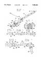
- FIG. 1is a perspective exploded isometric view of the instrument showing the handle, head, and a grommet to be inserted, according to the invention and showing the central axis A--A;
- FIG. 2is a cross sectional view of the head taken substantially along lines 2--2 of FIG. 1;
- FIG. 3is a perspective view showing the grommet of FIG. 1;
- FIG. 4is a perspective view showing a prostheses which is intended to cooperate with the grommet of FIG. 3;
- FIG. 5is a perspective view showing the prostheses of FIG. 4 with the protective grommet as they would be in place on the stem portions of the prostheses;
- FIG. 6is a perspective view showing the prostheses and grommets implanted in the medullary canals of adjoining bones of a finger joint;
- FIG. 7is a perspective view showing one stem portion of the prostheses implanted in the medullary canal of an adjoining bone of a joint, and a grommet press-fit into the medullary canal of the other adjoining bone;
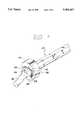
- FIG. 8is a perspective view showing a grommet being implanted into the medullary
- FIG. 9is a perspective exploded isometric view of the instrument showing the handle having a threaded portion, head, and a grommet to be inserted, according to the invention.
- FIG. 10is a cross-sectional view of the head taken substantially along lines 10--10 of FIG. 9;
- FIG. 11is a perspective view showing the insert that is to be press-fitted into the head of FIG. 10.
- the instrument 10comprises an elongated handle, generally indicated at 12, having a central axis, and a head which is indicated at 14.
- Handle 12preferably made of stainless steel, further includes opposed proximal 16 and distal 18 ends, distal end 18 being configured with a first connection portion 20 for interconnecting the handle and head 14 with one another.
- the head 14includes a base 22 with a protruding post 24 adapted for receiving grommet 26 to be implanted into the medullary canal. Means are further provided for removably securing head 14 to handle 12, as will be described in more detail below.
- head 14has opposed proximal 28 and distal 30 portions, with base 22 extending axially from the distal portion.
- the proximal portion 28is configured with a second connection portion 32 for mating with first connection portion 20 of handle 12, wherein head 14 and the handle are removably interconnected.
- Head 14is formed from a high density TEFLON® or other material which is nonabrasive to a prostheses or grommet being implanted, and Is sized to be interchangeable, allowing a single handle to be used with different head sizes corresponding to different grommet sizes.
- base 22is generally rectangular in cross-section, corresponding to rectangular flanged section 34 of grommet 26, shown in FIG. 3.
- Base 22supports grommet 26 and distributes the forces exerted during press-fitting of the grommet into the medullary canal 50, to flanged section 34, reducing the risk of bending the grommet.
- Base 22further includes horizontal leading edge 36 having radius R adapted for mating with radius flanged section 38 also having a radius r, of implantable grommet 26.
- post 24protrudes distally from base 22 and includes a cross-section tapered in a distal direction from a thicker portion 40 at the intersection of the post with the base.
- the tapered cross-section of post 24is configured to mate with protrusion 42 of grommet 26 as the grommet is situated on the post for implantation.
- the length of post 24is dependent on the size of the particular implant, and of sufficient length to hold grommet 26 on the post.
- Grommet 26is of the type conventionally used in finger and toe joint replacement surgery. A further detailed description of the structure and use of the grommet may be found in U.S. Pat. No. 4,158,893 issued Jun. 26, 1979, and entitled: PROTECTIVE SLEEVE FOR IMPLANTABLE PROSTHESES AND METHOD OF PROTECTING THE PROSTHESIS, the entire disclosure of which is expressly incorporated by reference herein and relied upon.
- the means for securing head 14 to handle 12preferably takes the form of thread portion 43 formed in first connection portion 20 of handle 12 which is threaded into second connection portion 32 via insert 45.
- Insert 45preferably made of stainless steel, further having internal threads 47 is press-fitted into second connecting portion 32 to threadedly interconnect head 14 and handle 12.
- the structure for head 14 and grommet 16are the same as FIGS. 1-3 with the exception of the above reference numbers.
- the means for securing head 14 to handle 12takes the form of ball plunger arrangement 44 formed in first connection portion 20 of handle 12, which is retained in a pilot hole 46 formed in head 14.
- First connection portion 20 including ball plunger arrangement 44is inserted into second connection portion 32 formed in the proximal portion 28 of base 22. With the first connection portion 20 inserted in second connection portion 32, handle 12 is rotated until the ball plunger arrangement 44 engages pilot hole 46 to interconnect head 14 and the handle. Head 14 is easily disconnected from handle 12 by further rotating the handle until ball plunger arrangement 44 disengages pilot hole 46.
- a surgeoncan quickly interchange different head sizes to correspond with different grommet sizes used during surgery while using the same handle.
- the grommet 26(FIG. 3), and prostheses 48, (FIGS. 4-7) are implanted into the prepared medullary canal 50 of bone 56 surgically as follows.
- the canal 50is first drilled and reamed as shown in phantom in FIG. 6, the reaming corresponding to the dimensions of stems 52, 54 of prostheses 48.
- grommets 26are situated over stems 52, 54 (FIGS. 5-7).
- Grommet 26protects stems 52 and 54 from lacerations that may occur from sharp edges of bones adjacent the medullary canal 50. Lacerations of stems 52 and 54 are believed to be the starting point of tears, which could ultimately lead to premature joint failure.
- grommet 26is shown situated on post 24 of base 22, and aligned with horizontal leading edge 36 of the base. With grommet 26 situated on post 24, the surgeon then press-fits the grommet into canal 50.
Landscapes
- Health & Medical Sciences (AREA)
- Orthopedic Medicine & Surgery (AREA)
- Transplantation (AREA)
- Heart & Thoracic Surgery (AREA)
- Life Sciences & Earth Sciences (AREA)
- Oral & Maxillofacial Surgery (AREA)
- Engineering & Computer Science (AREA)
- Biomedical Technology (AREA)
- Veterinary Medicine (AREA)
- Vascular Medicine (AREA)
- Cardiology (AREA)
- Animal Behavior & Ethology (AREA)
- General Health & Medical Sciences (AREA)
- Public Health (AREA)
- Physical Education & Sports Medicine (AREA)
- Prostheses (AREA)
- Surgical Instruments (AREA)
Abstract
Description
Claims (21)
Priority Applications (1)
| Application Number | Priority Date | Filing Date | Title |
|---|---|---|---|
| US08/310,651US5484443A (en) | 1992-01-03 | 1994-09-22 | Instrument for inserting a protective sleeve into the medullary canal of a bone |
Applications Claiming Priority (3)
| Application Number | Priority Date | Filing Date | Title |
|---|---|---|---|
| US81726592A | 1992-01-03 | 1992-01-03 | |
| US3751093A | 1993-03-24 | 1993-03-24 | |
| US08/310,651US5484443A (en) | 1992-01-03 | 1994-09-22 | Instrument for inserting a protective sleeve into the medullary canal of a bone |
Related Parent Applications (1)
| Application Number | Title | Priority Date | Filing Date |
|---|---|---|---|
| US3751093AContinuation | 1992-01-03 | 1993-03-24 |
Publications (1)
| Publication Number | Publication Date |
|---|---|
| US5484443Atrue US5484443A (en) | 1996-01-16 |
Family
ID=25222694
Family Applications (1)
| Application Number | Title | Priority Date | Filing Date |
|---|---|---|---|
| US08/310,651Expired - Fee RelatedUS5484443A (en) | 1992-01-03 | 1994-09-22 | Instrument for inserting a protective sleeve into the medullary canal of a bone |
Country Status (4)
| Country | Link |
|---|---|
| US (1) | US5484443A (en) |
| EP (1) | EP0550284A2 (en) |
| JP (1) | JPH05253243A (en) |
| CA (1) | CA2086574A1 (en) |
Cited By (25)
| Publication number | Priority date | Publication date | Assignee | Title |
|---|---|---|---|---|
| WO1999021515A1 (en) | 1997-10-27 | 1999-05-06 | University Of Florida Tissue Bank, Inc. | Segmentally demineralized bone implant |
| US6652592B1 (en) | 1997-10-27 | 2003-11-25 | Regeneration Technologies, Inc. | Segmentally demineralized bone implant |
| US20040015239A1 (en)* | 2002-05-23 | 2004-01-22 | Beguec Pierre Le | Apparatus for the preparation of a femur bone for for the implantation of a prosthesis |
| US20040030386A1 (en)* | 2000-12-08 | 2004-02-12 | Todd Boyce | Segmentally demineralized bone implant and method for its manufacture |
| US20060247774A1 (en)* | 2005-04-29 | 2006-11-02 | Gil Carlos E | Spinal implant |
| US8608785B2 (en) | 2010-06-02 | 2013-12-17 | Wright Medical Technology, Inc. | Hammer toe implant with expansion portion for retrograde approach |
| US8702809B2 (en) | 2007-09-14 | 2014-04-22 | Purdue Research Foundation | Demineralized cancellous bone scaffolds |
| US8945232B2 (en) | 2012-12-31 | 2015-02-03 | Wright Medical Technology, Inc. | Ball and socket implants for correction of hammer toes and claw toes |
| US9044287B2 (en) | 2010-06-02 | 2015-06-02 | Wright Medical Technology, Inc. | Hammer toe implant method |
| US9161789B2 (en) | 2007-03-20 | 2015-10-20 | Memometal Technologies | Osteosynthesis device |
| US9168074B2 (en) | 2008-09-09 | 2015-10-27 | Memometal Technologies | Resorptive intramedullary implant between two bones or two bone fragments |
| US9283007B2 (en) | 2005-04-14 | 2016-03-15 | Stryker European Holdings I, Llc | Device for osteosyntheses or arthrodeses of two- bone parts, in particular of the hand and / or foot |
| US9474561B2 (en) | 2013-11-19 | 2016-10-25 | Wright Medical Technology, Inc. | Two-wire technique for installing hammertoe implant |
| US9498273B2 (en) | 2010-06-02 | 2016-11-22 | Wright Medical Technology, Inc. | Orthopedic implant kit |
| US9498266B2 (en) | 2014-02-12 | 2016-11-22 | Wright Medical Technology, Inc. | Intramedullary implant, system, and method for inserting an implant into a bone |
| US9545274B2 (en) | 2014-02-12 | 2017-01-17 | Wright Medical Technology, Inc. | Intramedullary implant, system, and method for inserting an implant into a bone |
| US20170100172A1 (en)* | 2011-12-12 | 2017-04-13 | Wright Medical Technology, Inc. | Fusion implant |
| US9724139B2 (en) | 2013-10-01 | 2017-08-08 | Wright Medical Technology, Inc. | Hammer toe implant and method |
| US9724140B2 (en) | 2010-06-02 | 2017-08-08 | Wright Medical Technology, Inc. | Tapered, cylindrical cruciform hammer toe implant and method |
| US9757168B2 (en) | 2015-03-03 | 2017-09-12 | Howmedica Osteonics Corp. | Orthopedic implant and methods of implanting and removing same |
| US9808296B2 (en) | 2014-09-18 | 2017-11-07 | Wright Medical Technology, Inc. | Hammertoe implant and instrument |
| US10080597B2 (en) | 2014-12-19 | 2018-09-25 | Wright Medical Technology, Inc. | Intramedullary anchor for interphalangeal arthrodesis |
| US10470807B2 (en) | 2016-06-03 | 2019-11-12 | Stryker European Holdings I, Llc | Intramedullary implant and method of use |
| US11116509B2 (en) | 2017-11-10 | 2021-09-14 | Avantec Vascular Corporation | System and method for delivering an embolic device |
| US11382634B2 (en) | 2019-12-18 | 2022-07-12 | Avantec Vascular Corporation | Embolic device suited for ease of delivery and placement |
Citations (16)
| Publication number | Priority date | Publication date | Assignee | Title |
|---|---|---|---|---|
| US2187852A (en)* | 1936-08-18 | 1940-01-23 | William D Friddle | Fracture nail and fracture nail driver |
| US3036482A (en)* | 1960-09-02 | 1962-05-29 | Kenworthy Kenneth | Axial-impact type hand tool |
| US3334624A (en)* | 1963-09-26 | 1967-08-08 | Synthes Ag | Intramedullary nail |
| US3626935A (en)* | 1969-08-12 | 1971-12-14 | Gen Motors Corp | Surgical nail extractor |
| US4305394A (en)* | 1980-12-22 | 1981-12-15 | Bertuch Jr Charles J | Acetabular cup positioning instrument |
| US4423721A (en)* | 1978-09-04 | 1984-01-03 | Schwarzkopf Development Corporation | Device for insertion and extraction of medullary nails |
| US4462395A (en)* | 1983-03-02 | 1984-07-31 | Johnson Lanny L | Arthroscopic ligamentous and capsular fixation system |
| US4621630A (en)* | 1983-04-15 | 1986-11-11 | Pfizer Hospital Products Group, Inc. | Guide for femoral neck osteotomy |
| US4878918A (en)* | 1985-03-29 | 1989-11-07 | Gabor Tari | Mechanically fixed acetabular unit for prostheses and implantation device for fixing it into the cotyloid cavity |
| US4987904A (en)* | 1990-03-22 | 1991-01-29 | Wilson James T | Method and apparatus for bone size gauging |
| US4994064A (en)* | 1989-12-21 | 1991-02-19 | Aboczky Robert I | Instrument for orienting, inserting and impacting an acetabular cup prosthesis |
| US4993410A (en)* | 1989-05-01 | 1991-02-19 | Kimsey Timothy P | Prosthetic removal device |
| US5030219A (en)* | 1990-01-22 | 1991-07-09 | Boehringer Mannheim Corporation | Glenoid component installation tools |
| US5061270A (en)* | 1991-03-18 | 1991-10-29 | Aboczky Robert I | System for orienting, inserting and impacting an acetabular cup prosthesis |
| US5061271A (en)* | 1989-02-27 | 1991-10-29 | Boehringer Mannheim Corporation | Tool for separating components of a modular joint prosthesis |
| US5071420A (en)* | 1991-04-25 | 1991-12-10 | Depuy Du Pont Orthopaedics | Isometry testing device |
- 1992
- 1992-12-28JPJP4347673Apatent/JPH05253243A/enactivePending
- 1992-12-31EPEP92311896Apatent/EP0550284A2/ennot_activeWithdrawn
- 1992-12-31CACA002086574Apatent/CA2086574A1/ennot_activeAbandoned
- 1994
- 1994-09-22USUS08/310,651patent/US5484443A/ennot_activeExpired - Fee Related
Patent Citations (16)
| Publication number | Priority date | Publication date | Assignee | Title |
|---|---|---|---|---|
| US2187852A (en)* | 1936-08-18 | 1940-01-23 | William D Friddle | Fracture nail and fracture nail driver |
| US3036482A (en)* | 1960-09-02 | 1962-05-29 | Kenworthy Kenneth | Axial-impact type hand tool |
| US3334624A (en)* | 1963-09-26 | 1967-08-08 | Synthes Ag | Intramedullary nail |
| US3626935A (en)* | 1969-08-12 | 1971-12-14 | Gen Motors Corp | Surgical nail extractor |
| US4423721A (en)* | 1978-09-04 | 1984-01-03 | Schwarzkopf Development Corporation | Device for insertion and extraction of medullary nails |
| US4305394A (en)* | 1980-12-22 | 1981-12-15 | Bertuch Jr Charles J | Acetabular cup positioning instrument |
| US4462395A (en)* | 1983-03-02 | 1984-07-31 | Johnson Lanny L | Arthroscopic ligamentous and capsular fixation system |
| US4621630A (en)* | 1983-04-15 | 1986-11-11 | Pfizer Hospital Products Group, Inc. | Guide for femoral neck osteotomy |
| US4878918A (en)* | 1985-03-29 | 1989-11-07 | Gabor Tari | Mechanically fixed acetabular unit for prostheses and implantation device for fixing it into the cotyloid cavity |
| US5061271A (en)* | 1989-02-27 | 1991-10-29 | Boehringer Mannheim Corporation | Tool for separating components of a modular joint prosthesis |
| US4993410A (en)* | 1989-05-01 | 1991-02-19 | Kimsey Timothy P | Prosthetic removal device |
| US4994064A (en)* | 1989-12-21 | 1991-02-19 | Aboczky Robert I | Instrument for orienting, inserting and impacting an acetabular cup prosthesis |
| US5030219A (en)* | 1990-01-22 | 1991-07-09 | Boehringer Mannheim Corporation | Glenoid component installation tools |
| US4987904A (en)* | 1990-03-22 | 1991-01-29 | Wilson James T | Method and apparatus for bone size gauging |
| US5061270A (en)* | 1991-03-18 | 1991-10-29 | Aboczky Robert I | System for orienting, inserting and impacting an acetabular cup prosthesis |
| US5071420A (en)* | 1991-04-25 | 1991-12-10 | Depuy Du Pont Orthopaedics | Isometry testing device |
Cited By (57)
| Publication number | Priority date | Publication date | Assignee | Title |
|---|---|---|---|---|
| US6090998A (en)* | 1997-10-27 | 2000-07-18 | University Of Florida | Segmentally demineralized bone implant |
| US6652592B1 (en) | 1997-10-27 | 2003-11-25 | Regeneration Technologies, Inc. | Segmentally demineralized bone implant |
| WO1999021515A1 (en) | 1997-10-27 | 1999-05-06 | University Of Florida Tissue Bank, Inc. | Segmentally demineralized bone implant |
| US20040030386A1 (en)* | 2000-12-08 | 2004-02-12 | Todd Boyce | Segmentally demineralized bone implant and method for its manufacture |
| US20040015239A1 (en)* | 2002-05-23 | 2004-01-22 | Beguec Pierre Le | Apparatus for the preparation of a femur bone for for the implantation of a prosthesis |
| US7112203B2 (en)* | 2002-05-23 | 2006-09-26 | Centerpulse Orthopedics Ltd. | Apparatus for the preparation of a femur bone for the implantation of a prosthesis |
| US11478285B2 (en) | 2005-04-14 | 2022-10-25 | Stryker European Operations Holdings Llc | Device for osteosyntheses or arthrodesis of two-bone parts, in particular of the hand and/or foot |
| US10022167B2 (en) | 2005-04-14 | 2018-07-17 | Stryker European Holdings I, Llc | Method of osteosyntheses or arthrodesis of two-bone parts, in particular of the hand and / or foot |
| US9492215B2 (en) | 2005-04-14 | 2016-11-15 | Stryker European Holdings I, Llc | Method of osteosyntheses or arthrodeses of two- bone parts, in particular of the hand and / or foot |
| US11006984B2 (en) | 2005-04-14 | 2021-05-18 | Stryker European Operations Holdings Llc | Device for osteosyntheses or arthrodesis of two-bone parts, in particular of the hand and / or foot |
| US9283007B2 (en) | 2005-04-14 | 2016-03-15 | Stryker European Holdings I, Llc | Device for osteosyntheses or arthrodeses of two- bone parts, in particular of the hand and / or foot |
| US20060247774A1 (en)* | 2005-04-29 | 2006-11-02 | Gil Carlos E | Spinal implant |
| US8147547B2 (en) | 2005-04-29 | 2012-04-03 | Warsaw Orthopedic, Inc. | Spinal implant |
| US12396766B2 (en) | 2007-03-20 | 2025-08-26 | Stryker European Operations Holdings Llc | Osteosynthesis device |
| US9839453B2 (en) | 2007-03-20 | 2017-12-12 | Stryker European Holdings I, Llc | Osteosynthesis device |
| US9161789B2 (en) | 2007-03-20 | 2015-10-20 | Memometal Technologies | Osteosynthesis device |
| US10912594B2 (en) | 2007-03-20 | 2021-02-09 | Stryker European Holdings I, Llc | Osteosynthesis device |
| EP3708126A1 (en) | 2007-09-14 | 2020-09-16 | Purdue Research Foundation | Demineralized cancellous bone scaffolds |
| US8702809B2 (en) | 2007-09-14 | 2014-04-22 | Purdue Research Foundation | Demineralized cancellous bone scaffolds |
| US9364584B2 (en) | 2007-09-14 | 2016-06-14 | Purdue Research Foundation | Demineralized cancellous bone scaffolds |
| US12390255B2 (en) | 2008-09-09 | 2025-08-19 | Stryker European Operations Holdings Llc | Resorptive intramedullary implant between two bones or two bone fragments |
| US12059186B2 (en) | 2008-09-09 | 2024-08-13 | Stryker European Operations Holdings Llc | Resorptive intramedullary implant between two bones or two bone fragments |
| US9168074B2 (en) | 2008-09-09 | 2015-10-27 | Memometal Technologies | Resorptive intramedullary implant between two bones or two bone fragments |
| US10383671B2 (en) | 2008-09-09 | 2019-08-20 | Stryker European Holdings I, Llc | Resorptive intramedullary implant between two bones or two bone fragments |
| US12383319B2 (en) | 2008-09-09 | 2025-08-12 | Stryker European Operations Holdings Llc | Resorptive intramedullary implant between two bones or two bone fragments |
| US10736676B2 (en) | 2010-06-02 | 2020-08-11 | Wright Medical Technology, Inc. | Orthopedic implant kit |
| US9498273B2 (en) | 2010-06-02 | 2016-11-22 | Wright Medical Technology, Inc. | Orthopedic implant kit |
| US9125704B2 (en) | 2010-06-02 | 2015-09-08 | Wright Medical Technology, Inc. | Hammer toe implant with expansion portion for retrograde approach |
| US9724140B2 (en) | 2010-06-02 | 2017-08-08 | Wright Medical Technology, Inc. | Tapered, cylindrical cruciform hammer toe implant and method |
| US9044287B2 (en) | 2010-06-02 | 2015-06-02 | Wright Medical Technology, Inc. | Hammer toe implant method |
| US8608785B2 (en) | 2010-06-02 | 2013-12-17 | Wright Medical Technology, Inc. | Hammer toe implant with expansion portion for retrograde approach |
| US9072564B2 (en) | 2010-06-02 | 2015-07-07 | Wright Medical Technology, Inc. | Hammer toe implant and method |
| US9877753B2 (en) | 2010-06-02 | 2018-01-30 | Wright Medical Technology, Inc. | Orthopedic implant kit |
| US9949775B2 (en) | 2010-06-02 | 2018-04-24 | Wright Medical Technology, Inc. | Hammer toe implant with expansion portion for retrograde approach |
| US9603643B2 (en) | 2010-06-02 | 2017-03-28 | Wright Medical Technology, Inc. | Hammer toe implant with expansion portion for retrograde approach |
| US10463407B2 (en)* | 2011-12-12 | 2019-11-05 | Wright Medical Technology, Inc. | Fusion implant |
| US20170100172A1 (en)* | 2011-12-12 | 2017-04-13 | Wright Medical Technology, Inc. | Fusion implant |
| US8945232B2 (en) | 2012-12-31 | 2015-02-03 | Wright Medical Technology, Inc. | Ball and socket implants for correction of hammer toes and claw toes |
| US9504582B2 (en) | 2012-12-31 | 2016-11-29 | Wright Medical Technology, Inc. | Ball and socket implants for correction of hammer toes and claw toes |
| US10278828B2 (en) | 2012-12-31 | 2019-05-07 | Wright Medical Technology, Inc. | Ball and socket implants for correction of hammer toes and claw toes |
| US9724139B2 (en) | 2013-10-01 | 2017-08-08 | Wright Medical Technology, Inc. | Hammer toe implant and method |
| US9675392B2 (en) | 2013-11-19 | 2017-06-13 | Wright Medical Technology, Inc. | Two-wire technique for installing hammertoe implant |
| US9474561B2 (en) | 2013-11-19 | 2016-10-25 | Wright Medical Technology, Inc. | Two-wire technique for installing hammertoe implant |
| US9545274B2 (en) | 2014-02-12 | 2017-01-17 | Wright Medical Technology, Inc. | Intramedullary implant, system, and method for inserting an implant into a bone |
| US9498266B2 (en) | 2014-02-12 | 2016-11-22 | Wright Medical Technology, Inc. | Intramedullary implant, system, and method for inserting an implant into a bone |
| US10299840B2 (en) | 2014-09-18 | 2019-05-28 | Wright Medical Technology, Inc. | Hammertoe implant and instrument |
| US9808296B2 (en) | 2014-09-18 | 2017-11-07 | Wright Medical Technology, Inc. | Hammertoe implant and instrument |
| US10080597B2 (en) | 2014-12-19 | 2018-09-25 | Wright Medical Technology, Inc. | Intramedullary anchor for interphalangeal arthrodesis |
| US9757168B2 (en) | 2015-03-03 | 2017-09-12 | Howmedica Osteonics Corp. | Orthopedic implant and methods of implanting and removing same |
| US10702318B2 (en) | 2015-03-03 | 2020-07-07 | Howmedica Osteonics Corp. | Orthopedic implant and methods of implanting and removing same |
| US11672576B2 (en) | 2015-03-03 | 2023-06-13 | Howmedica Osteonics Corp. | Orthopedic implant and methods of implanting and removing same |
| US12383318B2 (en) | 2015-03-03 | 2025-08-12 | Howmedica Osteonics Corp. | Orthopedic implant and methods of implanting and removing same |
| US10470807B2 (en) | 2016-06-03 | 2019-11-12 | Stryker European Holdings I, Llc | Intramedullary implant and method of use |
| US11992248B2 (en) | 2016-06-03 | 2024-05-28 | Stryker European Operations Holdings Llc | Intramedullary implant and method of use |
| US11272966B2 (en) | 2016-06-03 | 2022-03-15 | Stryker European Operations Holdings Llc | Intramedullary implant and method of use |
| US11116509B2 (en) | 2017-11-10 | 2021-09-14 | Avantec Vascular Corporation | System and method for delivering an embolic device |
| US11382634B2 (en) | 2019-12-18 | 2022-07-12 | Avantec Vascular Corporation | Embolic device suited for ease of delivery and placement |
Also Published As
| Publication number | Publication date |
|---|---|
| CA2086574A1 (en) | 1993-07-04 |
| EP0550284A2 (en) | 1993-07-07 |
| JPH05253243A (en) | 1993-10-05 |
Similar Documents
| Publication | Publication Date | Title |
|---|---|---|
| US5484443A (en) | Instrument for inserting a protective sleeve into the medullary canal of a bone | |
| US5437675A (en) | Polygonal bone punch | |
| US5899907A (en) | Instrumentation for proximal femoral compaction broaching | |
| EP0626155B1 (en) | Absorbable medullary plug | |
| EP0329854B1 (en) | Modular shoulder prothesis | |
| JP4152452B2 (en) | Prosthesis mounting device | |
| US4385405A (en) | Hip prosthesis and its method of fitting | |
| US5489311A (en) | Prosthesis with orientable bearing surface | |
| US3720959A (en) | Mandibular prosthetic apparatus | |
| US9295556B2 (en) | Minimally invasive total hip replacement | |
| US5554192A (en) | Intramedullary implant stem and centralizer | |
| US5387216A (en) | Intramedullary based instrument systems for total knee revision | |
| US5108449A (en) | Femoral component for a hip prosthesis | |
| US20080147203A1 (en) | Modular plate and keel provisionals | |
| US5057101A (en) | Femoral prosthesis with centering sleeve | |
| US4728330A (en) | Prosthetic bone or tooth implant and a method of surgically implanting the same | |
| US20080154276A1 (en) | Method and instruments for inserting modular implant components | |
| DE10360390B4 (en) | Joint socket for a hip endoprosthesis | |
| KR20000070929A (en) | Hip prosthesis and method for fitting such hip prosthesis | |
| WO1992012691A1 (en) | Endoprosthesis, especially for the hip joint | |
| HK137893A (en) | Implantable fixation means for extra-oral applications | |
| US5441501A (en) | Intermedullary rasp with detachable extension end | |
| JPH05500177A (en) | bone graft | |
| EP1070489B1 (en) | Femoral prosthesis device | |
| EP1446076B1 (en) | Femoral neck endoprosthesis for an artificial hip joint |
Legal Events
| Date | Code | Title | Description |
|---|---|---|---|
| AS | Assignment | Owner name:STATE STREET BANK AND TRUST COMPANY, N.A., MASSACH Free format text:SECURITY INTEREST;ASSIGNOR:WRIGHT MEDICAL TECHNOLOGY, INC.;REEL/FRAME:008650/0778 Effective date:19970806 | |
| REMI | Maintenance fee reminder mailed | ||
| AS | Assignment | Owner name:CHASE MANHATTAN BANK, AS COLLATERAL AGENT, THE, NE Free format text:SECURITY INTEREST;ASSIGNOR:WRIGHT MEDICAL TECHNOLOGY, INC., A DELAWARE CORPORATION;REEL/FRAME:010506/0341 Effective date:19991220 | |
| LAPS | Lapse for failure to pay maintenance fees | ||
| FP | Lapsed due to failure to pay maintenance fee | Effective date:20000116 | |
| AS | Assignment | Owner name:WRIGHT MEDICAL TECHNOLOGY, INC., TENNESSEE Free format text:TERMINATION AND RELEASE OF SECURITY INTEREST;ASSIGNOR:STATE STREET BANK AND TRUST COMPANY, N.A.;REEL/FRAME:011571/0989 Effective date:19991220 | |
| AS | Assignment | Owner name:CHASE MANHATTAN BANK, AS COLLATERAL AGENT FOR SECU Free format text:GUARANTEE AND COLLATERAL AGREEMENT;ASSIGNOR:WRIGHT MEDICAL TECHNOLOGY, INC.;REEL/FRAME:012066/0233 Effective date:20010801 | |
| AS | Assignment | Owner name:WRIGHT MEDICAL TECHNOLOGY, INC., TENNESSEE Free format text:TERMINATION AND RELEASE OF SECURITY INTEREST;ASSIGNOR:CHASE MANHATTAN BANK, AS COLLATERAL AGENT FOR SECURED PARTIES, THE;REEL/FRAME:012066/0327 Effective date:20010801 | |
| STCH | Information on status: patent discontinuation | Free format text:PATENT EXPIRED DUE TO NONPAYMENT OF MAINTENANCE FEES UNDER 37 CFR 1.362 |