US5484409A - Intravascular catheter and method for use thereof - Google Patents
Intravascular catheter and method for use thereofDownload PDFInfo
- Publication number
- US5484409A US5484409AUS08/023,950US2395093AUS5484409AUS 5484409 AUS5484409 AUS 5484409AUS 2395093 AUS2395093 AUS 2395093AUS 5484409 AUS5484409 AUS 5484409A
- Authority
- US
- United States
- Prior art keywords
- guide wire
- balloon
- catheter
- distal
- lumen
- Prior art date
- Legal status (The legal status is an assumption and is not a legal conclusion. Google has not performed a legal analysis and makes no representation as to the accuracy of the status listed.)
- Expired - Lifetime
Links
Images


Classifications
- A—HUMAN NECESSITIES
- A61—MEDICAL OR VETERINARY SCIENCE; HYGIENE
- A61M—DEVICES FOR INTRODUCING MEDIA INTO, OR ONTO, THE BODY; DEVICES FOR TRANSDUCING BODY MEDIA OR FOR TAKING MEDIA FROM THE BODY; DEVICES FOR PRODUCING OR ENDING SLEEP OR STUPOR
- A61M25/00—Catheters; Hollow probes
- A61M25/10—Balloon catheters
- A61M25/104—Balloon catheters used for angioplasty
- A—HUMAN NECESSITIES
- A61—MEDICAL OR VETERINARY SCIENCE; HYGIENE
- A61M—DEVICES FOR INTRODUCING MEDIA INTO, OR ONTO, THE BODY; DEVICES FOR TRANSDUCING BODY MEDIA OR FOR TAKING MEDIA FROM THE BODY; DEVICES FOR PRODUCING OR ENDING SLEEP OR STUPOR
- A61M25/00—Catheters; Hollow probes
- A61M25/0021—Catheters; Hollow probes characterised by the form of the tubing
- A61M25/0023—Catheters; Hollow probes characterised by the form of the tubing by the form of the lumen, e.g. cross-section, variable diameter
- A—HUMAN NECESSITIES
- A61—MEDICAL OR VETERINARY SCIENCE; HYGIENE
- A61M—DEVICES FOR INTRODUCING MEDIA INTO, OR ONTO, THE BODY; DEVICES FOR TRANSDUCING BODY MEDIA OR FOR TAKING MEDIA FROM THE BODY; DEVICES FOR PRODUCING OR ENDING SLEEP OR STUPOR
- A61M25/00—Catheters; Hollow probes
- A61M25/01—Introducing, guiding, advancing, emplacing or holding catheters
- A61M25/0105—Steering means as part of the catheter or advancing means; Markers for positioning
- A—HUMAN NECESSITIES
- A61—MEDICAL OR VETERINARY SCIENCE; HYGIENE
- A61M—DEVICES FOR INTRODUCING MEDIA INTO, OR ONTO, THE BODY; DEVICES FOR TRANSDUCING BODY MEDIA OR FOR TAKING MEDIA FROM THE BODY; DEVICES FOR PRODUCING OR ENDING SLEEP OR STUPOR
- A61M25/00—Catheters; Hollow probes
- A61M25/0043—Catheters; Hollow probes characterised by structural features
- A61M25/0045—Catheters; Hollow probes characterised by structural features multi-layered, e.g. coated
- A61M2025/0046—Coatings for improving slidability
- A61M2025/0047—Coatings for improving slidability the inner layer having a higher lubricity
- A—HUMAN NECESSITIES
- A61—MEDICAL OR VETERINARY SCIENCE; HYGIENE
- A61M—DEVICES FOR INTRODUCING MEDIA INTO, OR ONTO, THE BODY; DEVICES FOR TRANSDUCING BODY MEDIA OR FOR TAKING MEDIA FROM THE BODY; DEVICES FOR PRODUCING OR ENDING SLEEP OR STUPOR
- A61M25/00—Catheters; Hollow probes
- A61M25/0067—Catheters; Hollow probes characterised by the distal end, e.g. tips
- A61M25/0074—Dynamic characteristics of the catheter tip, e.g. openable, closable, expandable or deformable
- A61M2025/0079—Separate user-activated means, e.g. guidewires, guide tubes, balloon catheters or sheaths, for sealing off an orifice, e.g. a lumen or side holes, of a catheter
- A—HUMAN NECESSITIES
- A61—MEDICAL OR VETERINARY SCIENCE; HYGIENE
- A61M—DEVICES FOR INTRODUCING MEDIA INTO, OR ONTO, THE BODY; DEVICES FOR TRANSDUCING BODY MEDIA OR FOR TAKING MEDIA FROM THE BODY; DEVICES FOR PRODUCING OR ENDING SLEEP OR STUPOR
- A61M25/00—Catheters; Hollow probes
- A61M2025/0098—Catheters; Hollow probes having a strain relief at the proximal end, e.g. sleeve
- A—HUMAN NECESSITIES
- A61—MEDICAL OR VETERINARY SCIENCE; HYGIENE
- A61M—DEVICES FOR INTRODUCING MEDIA INTO, OR ONTO, THE BODY; DEVICES FOR TRANSDUCING BODY MEDIA OR FOR TAKING MEDIA FROM THE BODY; DEVICES FOR PRODUCING OR ENDING SLEEP OR STUPOR
- A61M25/00—Catheters; Hollow probes
- A61M25/01—Introducing, guiding, advancing, emplacing or holding catheters
- A61M2025/0175—Introducing, guiding, advancing, emplacing or holding catheters having telescopic features, interengaging nestable members movable in relations to one another
- A—HUMAN NECESSITIES
- A61—MEDICAL OR VETERINARY SCIENCE; HYGIENE
- A61M—DEVICES FOR INTRODUCING MEDIA INTO, OR ONTO, THE BODY; DEVICES FOR TRANSDUCING BODY MEDIA OR FOR TAKING MEDIA FROM THE BODY; DEVICES FOR PRODUCING OR ENDING SLEEP OR STUPOR
- A61M25/00—Catheters; Hollow probes
- A61M25/01—Introducing, guiding, advancing, emplacing or holding catheters
- A61M2025/0183—Rapid exchange or monorail catheters
- A—HUMAN NECESSITIES
- A61—MEDICAL OR VETERINARY SCIENCE; HYGIENE
- A61M—DEVICES FOR INTRODUCING MEDIA INTO, OR ONTO, THE BODY; DEVICES FOR TRANSDUCING BODY MEDIA OR FOR TAKING MEDIA FROM THE BODY; DEVICES FOR PRODUCING OR ENDING SLEEP OR STUPOR
- A61M25/00—Catheters; Hollow probes
- A61M25/10—Balloon catheters
- A61M2025/1043—Balloon catheters with special features or adapted for special applications
- A61M2025/1063—Balloon catheters with special features or adapted for special applications having only one lumen used for guide wire and inflation, e.g. to minimise the diameter
- A—HUMAN NECESSITIES
- A61—MEDICAL OR VETERINARY SCIENCE; HYGIENE
- A61M—DEVICES FOR INTRODUCING MEDIA INTO, OR ONTO, THE BODY; DEVICES FOR TRANSDUCING BODY MEDIA OR FOR TAKING MEDIA FROM THE BODY; DEVICES FOR PRODUCING OR ENDING SLEEP OR STUPOR
- A61M25/00—Catheters; Hollow probes
- A61M25/10—Balloon catheters
- A61M2025/1043—Balloon catheters with special features or adapted for special applications
- A61M2025/1079—Balloon catheters with special features or adapted for special applications having radio-opaque markers in the region of the balloon
- A—HUMAN NECESSITIES
- A61—MEDICAL OR VETERINARY SCIENCE; HYGIENE
- A61M—DEVICES FOR INTRODUCING MEDIA INTO, OR ONTO, THE BODY; DEVICES FOR TRANSDUCING BODY MEDIA OR FOR TAKING MEDIA FROM THE BODY; DEVICES FOR PRODUCING OR ENDING SLEEP OR STUPOR
- A61M25/00—Catheters; Hollow probes
- A61M25/0067—Catheters; Hollow probes characterised by the distal end, e.g. tips
- A61M25/0068—Static characteristics of the catheter tip, e.g. shape, atraumatic tip, curved tip or tip structure
- A61M25/0069—Tip not integral with tube
- A—HUMAN NECESSITIES
- A61—MEDICAL OR VETERINARY SCIENCE; HYGIENE
- A61M—DEVICES FOR INTRODUCING MEDIA INTO, OR ONTO, THE BODY; DEVICES FOR TRANSDUCING BODY MEDIA OR FOR TAKING MEDIA FROM THE BODY; DEVICES FOR PRODUCING OR ENDING SLEEP OR STUPOR
- A61M25/00—Catheters; Hollow probes
- A61M25/0067—Catheters; Hollow probes characterised by the distal end, e.g. tips
- A61M25/0074—Dynamic characteristics of the catheter tip, e.g. openable, closable, expandable or deformable
- A—HUMAN NECESSITIES
- A61—MEDICAL OR VETERINARY SCIENCE; HYGIENE
- A61M—DEVICES FOR INTRODUCING MEDIA INTO, OR ONTO, THE BODY; DEVICES FOR TRANSDUCING BODY MEDIA OR FOR TAKING MEDIA FROM THE BODY; DEVICES FOR PRODUCING OR ENDING SLEEP OR STUPOR
- A61M25/00—Catheters; Hollow probes
- A61M25/0067—Catheters; Hollow probes characterised by the distal end, e.g. tips
- A61M25/008—Strength or flexibility characteristics of the catheter tip
- A—HUMAN NECESSITIES
- A61—MEDICAL OR VETERINARY SCIENCE; HYGIENE
- A61M—DEVICES FOR INTRODUCING MEDIA INTO, OR ONTO, THE BODY; DEVICES FOR TRANSDUCING BODY MEDIA OR FOR TAKING MEDIA FROM THE BODY; DEVICES FOR PRODUCING OR ENDING SLEEP OR STUPOR
- A61M25/00—Catheters; Hollow probes
- A61M25/01—Introducing, guiding, advancing, emplacing or holding catheters
- A61M25/09—Guide wires
- A61M25/09016—Guide wires with mandrils
- A61M25/09025—Guide wires with mandrils with sliding mandrils
Definitions
- This inventionrelates to an improved intravascular catheter and in particular to an improved intravascular catheter that can have a very low profile and that allows for the exchange of a first catheter for another catheter over a guide wire, and methods for use thereof.
- Intravascular catheterization apparatuseshave proven to be useful and efficient for both therapeutic and diagnostic purposes.
- Intravascular catheterization therapiessuch as angioplasty, atherectomy, and laser irradiation, have been developed as alternatives to bypass surgery for treating vascular diseases or other conditions that occlude or reduce the lumen size of portions of a patient's vascular system.
- balloon angioplastyhas proven to be a useful and in many circumstances a preferred treatment for obstructive coronary diseases.
- intravascular diagnostic catheter apparatusesfor angiographics, ultrasonic imaging, and Doppler blood flow measurements for example, have been developed to measure or image the extent of an occlusion of a vessel, (e.g., stenosis). These intravascular diagnostic apparatuses may be used in conjunction with the aforementioned therapeutic apparatuses or may be used in conjunction with more invasive techniques such as coronary surgery.
- intravascular therapeutic and diagnostic apparatuseshave achieved acceptance because of their effectiveness as well as the fact that they can be used through a minor surgical procedure that is relatively non-disruptive to the patient compared to coronary surgery.
- These intravascular therapeutic and diagnostic apparatusesrely on the positioning of a catheter device into the vascular system of a patient via an incision at an accessible location which may be remote from the site of the occlusion or stenosis.
- the accessible locationmay be the femoral artery at the groin.
- the intravascular deviceis then advanced through the incision via the femoral artery to the desired coronary distal site.
- the angioplasty balloon catheterIn order to perform an angioplasty dilation, the angioplasty balloon catheter must be positioned across the stenosis in the arterial site.
- the stenosismay be located in a tortuous portion of the coronary vasculature and, furthermore, the obstructive arterial disease may impede crossing the stenosis with the balloon portion of the angioplasty catheter.
- not all arterial obstructionscan be successfully treated by present intravascular balloon catheter procedures because some arterial obstructions are not readily accessible to a balloon dilation catheter. Accordingly, there is a need for intravascular catheters of very low profile that can be positioned in narrow, tortuous regions of a person's vasculature.
- Intravascular therapeutic and diagnostic devicescome in various types and sizes suitable for the vessel size and location in which the treatment is to be performed. Sometimes, it becomes necessary to exchange a first therapeutic device for one of a different size after the first device has been positioned or after an unsuccessful attempt to position the first device. This may be necessitated because it becomes apparent that the first device is the wrong size or because it is determined that additional therapeutic or diagnostic procedures with a different size or type of device is required.
- One type of catheter designcommonly referred to a fixed-wire type catheter, includes a non-removable wire tip attached on a distal end of the intravascular catheter.
- the wire tipfacilitates maneuvering the catheter to the desired vessel site.
- a disadvantage of the fixed-wire type catheterthat is if it becomes necessary to exchange a first catheter for a second catheter, the maneuvering procedure must be repeated for the second catheter. As mentioned above, this can be sometimes a tedious and difficult procedure.
- an over-the-wire type catheterincludes a central lumen through the intravascular device that can accommodate a separate guide wire that is movable, and removable, in relation to the catheter to facilitate positioning the catheter in a remote vessel location over the guide wire.
- the catheterincludes a lumen adapted to receive the guide wire from a proximal end to the distal end of the device.
- the guide wireis initially loaded through the lumen of the over-the-wire catheter and extends out from the distal end thereof. Then, the guide wire and the intravascular catheter are advanced together and positioned in the vessel at the desired site.
- the guide wiremay be advanced distally of the distal end of the catheter and steered, as necessary, to traverse tortuous passages of the vessel.
- the guide wiremay then be withdrawn proximally through the lumen of the catheter or may be left in place extending from the distal end of the catheter during the procedure.
- the over-the-wire type catheterfacilitates exchanges.
- An intravascular catheter with an over-the-wire constructioncan be exchanged while leaving the distal tip of the guide wire in place by using an exchange wire which is a guide wire having a long length (e.g. 300 cm) so that a sufficiently long proximal portion of the guide wire extends out of the proximal end of the catheter so that the entire catheter can be withdrawn out completely over the wire while maintaining a hold on a proximal portion of the wire.
- Another way to perform an exchange with an over-the-wire type intravascular catheteris by using a guide wire extension.
- a variation of the over-the-wire type catheter that facilitates exchange of a first intravascular catheter with anotheris the single-operator exchange type design construction.
- the guide wireoccupies a position adjacent to the intravascular catheter along proximal and middle portions of the catheter and enters into a short guide wire lumen of the catheter via an opening in the catheter at a location in a distal portion of the catheter.
- the cathetercan be positioned in the patient's vessel by positioning a guide wire in the desired location and advancing the catheter device over the wire.
- the cathetercan be withdrawn proximally while the distal tip of the guide wire is left in position in the vessel site.
- the proximal end of the guide wire and the proximal end of the catheterare adjacent to each other, the proximal end of the guide wire can be held so that the position of the distal end of the guide wire in the patient's vessel can be maintained.
- the distance from the distal end of the catheter to the proximal guide wire lumen entranceis less than the length of the guide wire that extends proximally out of the guiding catheter.
- intravascular catheterssuch as the over-the-wire type and the single-operator type, that employ a separate guide wire provide advantages relating to exchanges, these types of catheters obtain this advantage at the expense of size.
- a separate guide wire lumenmust be provided through at least a portion of the catheter. This element unavoidably increases the overall dimensions of the catheter to at least some degree compared to the fixed-wire type catheter.
- the present inventionrelates to an intravascular catheter and a method for use thereof comprising an elongate shaft having an inflation lumen extending therethrough, a dilation balloon connected to and located at the distal portion of the shaft and communicating with the lumen, a small profile core wire extending through at least the intravascular implement and having a distal portion that extends distally from intravascular implement through a distal core wire opening located distally of the balloon and further in which the core wire is movable relative to the elongate shaft to allow withdrawal of the elongate shaft and the balloon while leaving the core wire positioned intravascularly, and a tip member connected to the core wire in a region thereof distal of the location at which the core wire extends distally of the core wire opening, the tip member having a profile larger than the opening.
- FIG. 1is a sectional side elevational view of a first preferred embodiment of a balloon dilation catheter of the present invention.
- FIG. 2is a sectional side elevational view of a second preferred embodiment of a balloon dilation catheter of the present invention.
- FIG. 3shows a longitudinal sectional view of a distal portion of the embodiment of the embodiment depicted in FIG. 2
- FIG. 4shows a sectional view of the along lines A-A' in FIG. 3.
- FIG. 5shows a longitudinal sectional view of an intermediate portion of the embodiment of the embodiment depicted in FIG. 2.
- FIG. 6shows a sectional view of the along lines B-B' in FIG. 5.
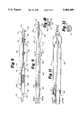
- FIG. 7is a sectional side elevational view of a third preferred embodiment of a balloon dilation catheter of the present invention.
- FIG. 8is a sectional side elevational view of a fourth preferred embodiment of a balloon dilation catheter of the present invention.
- FIG. 9is a sectional side elevational view of a fifth preferred embodiment of a balloon dilation catheter of the present invention.
- FIG. 10shows a sectional view of the along lines A-A' in FIG. 9.
- FIG. 11is a sectional side elevational view of a sixth preferred embodiment of a balloon dilation catheter of the present invention.
- FIG. 12shows a sectional view of the along lines A-A' in FIG. 12.
- FIG. 13is a sectional side elevational view of a seventh preferred embodiment of a balloon dilation catheter of the present invention.
- FIG. 14is a broken longitudinal sectional view depicting another embodiment of the present invention.
- FIG. 15depicts a section of a distal portion of the catheter of FIG. 14 shown in an uninflated condition (shown without the balloon portion for the sake of clarity) such as during positioning of the catheter.
- FIG. 16is a broken side view partially in section of the guide wire of the embodiment of FIG. 14.
- FIG. 17is an exploded perspective view of the manifold assembly in FIG. 14.
- FIG. 18is an exploded side view of the manifold assembly of FIG. 17.
- FIG. 19is a longitudinal sectional view of a portion of manifold assembly of FIG. 17 illustrating the manifold assembly in an inflation setting.
- FIG. 20is an exploded sectional view of the inflation port of FIG. 17.
- FIG. 21is a cross sectional view of the inflation port taken along lines 21--21 of FIG. 19 illustrating the inflation port in a venting setting.
- Embodiments of the present invention described hereinare dilation balloon catheters for use in PTCA procedures. It should be understood that these embodiments may be adapted to other types of intravascular therapeutic devices, such as atherectomy catheters, as well as diagnostic catheters, such as ultrasonic catheters.
- the balloon dilation catheter 10includes an elongate catheter shaft 14 formed of a tubular member 16 having a proximal portion 18 and a distal portion 22.
- a dilation balloon 26is located at and connected to the distal portion 22 of the catheter shaft 14.
- the balloon 26can be formed from a polyolefin copolymer or other polymer material.
- the balloon 26is formed of a polyolefin copolymer (such as that sold by DuPont under the tradename SURLYN as Resin No. 8527) using secondary treatment with 5 to 50 Mega-rad electron beam irradiation to enhance strength in the region of the balloon 26.
- the balloon 26is provided in a variety of conventional sizes suitable for PTCA use.
- a first lumen 32Extending through the catheter shaft 14 and specifically through the outer tubular member 16 is a first lumen 32.
- the dilation balloon 26is in fluid communication with the first lumen 32 of the catheter shaft 14.
- Inflation fluidis conveyed via the first lumen 32 from an inflation port 40 of a proximally located manifold 44 to inflate the balloon 26 and therefore dilate a vessel in a conventional manner known in the art.
- Located around the outer tubular member directly distal of the manifold 44is a strain relief member 46.
- the strain relief member 46may be piece of polymeric tubing and have a length of 5 to 10 cm.
- the outer tubular member 16 of the catheter shaft 14is formed of two portions.
- a proximal portion 48 of the outer tubular member 16is formed of a strong, relatively rigid material, such as a stainless steel hypotube formed of type 304 stainless steel.
- a distal portion 50 of the outer tubular member 16is formed of a relatively flexible material, such as a polymeric material like a polyolefin copolymer or polyethylene.
- the distal portion 50is formed of polyethylene and in particular a high density polyethylene (HDPE).
- the proximal portion 48 and the distal portion 50may be connected together by a bonding means such as an adhesive or a mechanical fit.
- the proximal portion 48 of the tubular member 16has an outer diameter of 0.028 inches, an inner diameter of 0.022 inches, and a length of 105 cm.
- the distal portion 50 of the tubular member 16has an outer diameter of 0.025 inches, an inner diameter of 0.019 inches, and a length of 30 cm.
- the proximal portion 48 of the shaft 14can be made of a material other than stainless steel.
- One alternative material that can be used for the shaftis a superelastic alloy. These alloys are also commonly referred to as shape memory alloys. Such an alloy is Tinel® which is available from Raychem, Inc of Menlo Park, Calif. Other materials that offer similar properties include nickel-titanium shape memory alloys available from Shape Memory Applications, Inc. of Sunnyvale, Calif. Nitinol is another such alloy. These materials are available as tubing having high elasticity resulting in a kink-resistant catheter shaft.
- tubing of these superelastic alloyscan be used for both the proximal and distal portions of the catheter shaft.
- proximal portion 48is made of tubing of a superelastic alloy, it preferably has an outer diameter of 0.028 and a wall thickness of 0.002 to 0.003.
- distal portion 50is made of tubing of a superelastic alloy, it preferably has an outer diameter of 0.020 and a wall thickness of 0.001 to 0.002. Because these materials are difficult to solder or braze, it may be preferred to join them to other substrates with adhesives. Also, in order to provide the tubing in the dimensions necessary for use, the materials may be processed by a centerless grinding operation.
- a kink resistant member 52is preferably located at and distally of the connection between the proximal and distal portions to provide for a transition in stiffness between the relatively rigid proximal portion 48 and the relatively flexible distal portion 50.
- the kink resistant member 52is formed of a spring coil extending across the connection location.
- the kink resistant memberis formed of a stainless steel coil that extends distally into the distal portion 50 approximately 5 cm.
- the spring coilis sized to closely fit in the lumen 32 of the outer tubular member 16.
- the kink resistant member 52may be bonded to the outer tubular member 16 or may be positioned by a press or mechanical fit.
- the kink resistant member 52may be formed by a wire extending distally of the proximal portion 48, and in particular, a tapered wire.
- the inner tubular member 56Located in the first lumen 32 is an inner tubular member 56.
- the inner tubular member 56also has a lumen, i.e., second lumen 58, extending therethrough.
- the tubular member 56extends through both the distal 50 and proximal 48 portions of the catheter shaft 14 and through the balloon 26.
- the inner tubular member 56occupies only a portion of the first lumen 32 thereby providing an annular region between the outer tubular member 16 and the inner tubular member 56 to allow for the conveyance of inflation fluid therein.
- the inner tubular member 56is formed of a relatively flexible material such as a medium density polyethylene.
- the inner tubular member 56has an outer diameter of 0.012 inches and an inner diameter of 0.010 inches and has a length of 140 cm.
- the core wire 62is a very low profile core wire.
- the core wirehas a diameter less than 0.010 inches, and preferably the core wire has a diameter of 0.006 to 0.008 inches.
- the core wire 62extends through the catheter shaft 14 in the inner tubular member lumen 56 and extends proximally of the manifold 44 from a second port 66 thereof.
- a distal portion 70 of the core wire 62extends distally from the catheter shaft 14 from a distal opening 72 located distally of the balloon 26. In this embodiment, the distal opening 72 communicates with the lumen 58 of the inner tubular member 56.
- the core wire 62preferably has a uniform outer diameter and is tapered distally. In a preferred embodiment the core wire is made of type 304 stainless steel.
- the tip member 76is preferably formed of a coil spring joined to the core wire 62. In a conventional manner, the core wire 62 is processed to have a reduced and flattened profile underneath the coil spring to provide additional flexibility.
- the tip member 76is preferably formed of a radiopaque material such as platinum, although other materials, such as stainless steel or even non-metallic polymers may be used as well.
- the tip member 76may be connected to the core 62 wire by brazing, soldering an adhesive, mechanical fit, or other connecting means.
- the tip member 76provides for a flexible, deformable tip for advancing and positioning the catheter 10 intravascularly with minimal trauma to the vessel.
- a rounded tip 78Located at the distal end of the tip member 76 is a rounded tip 78 which may be formed of solder or other material in a manner known in the art.
- the tip member 70is sized to conform closely in characteristics to a flexible spring tip incorporated on conventional fixed wire catheters to take advantage of the skills and familiarity already developed by practicing physicians with such conventional fixed wire type catheters. Accordingly, the spring tip is constructed so that it can be bent or otherwise formed, e.g. in a "J" shape, to facilitate positioning into the desired location of the artery.
- the marker 80is preferably formed of a small band or coil of radiopaque material such as platinum, gold, etc., that is bonded to the inner tubular member 56 directly underneath the balloon 26.
- the markermay be bonded by any conventional means, such as a mechanical fit, adhesives, etc.
- the marker 80is used in a conventional manner to assist the physician to locate and position the catheter fluoroscopically. Alternatively, the marker may be located at other positions, such as at the distal or proximal balloon waist areas, or multiple markers may be incorporated.
- the strain relief member 84may be a relatively short piece of polymeric tubing connected to the exterior of the inner tubular member 56 directly underneath the distal waist portion of the balloon 26.
- the strain relief member 84facilitates the connection of the flexible distal waist of the balloon 26 to the flexible inner tubular member 56 by reducing the bond gaps between the distal balloon waist and the shaft.
- the strain relief member 84also provides a transition from the relatively flexible spring tip to the relatively stiff balloon bond site. Also, the strain relief member acts like a funnel to facilitate loading of the core wire into the inner tubular member 56 such as during a catheter exchange.
- the manifold 44incorporates a securing means 88 to fix the proximal portion of the small profile core wire 62.
- the core wire 62When secured, the core wire 62 is fixed relative to the manifold both axially and rotationally. When so fixed, the core wire 62 and the elongate shaft 14 will function similarly to a conventional fixed wire type catheter.
- the securing means 88is preferably an easy to manipulate device that the physician can readily operate with one hand. Clamping devices for such a purpose are conventional and known to those of skill in the art.
- the securing means 88may include an annular ring having internal threads that engage corresponding external threads on the manifold body. Tightening of the annular member compresses a resilient gasket in an axial direction thereby causing it to clasp the core wire proximal end extending therethrough.
- An optional feature of this embodimentis a provision for torque transmission between the shaft 14 and the core wire 62. This feature is particularly advantageous because of the very small diameter of the core wire. This feature may be provided by incorporation of any of the torque transmission embodiments disclosed in copending application Ser. No. 07/583,437 filed Sep. 17, 1990, the entire disclosure of which is specifically incorporated herein by reference. In particular, it is preferred to incorporate a torque transition feature into this embodiment by forming a portion of the core wire 62 with an other-than-round profile in the region corresponding to the kink resistant member 52.
- the profile of the second lumen 58corresponds to the other-than-round shape of the core wire exterior profile so that torque can be transmitted to the distal portion of the core wire by rotation of the proximal end of the outer tubular member 16. It is preferred that the other-than-round external profile of the core wire 62 extend a distance along the core wire to allow advancing the core wire tip distally of the elongate shaft while still providing for torque transmission from the shaft to the core wire for steering purposes.
- the balloon catheter 10may be packaged with the core wire 62 already positioned in the shaft 14. Before use, the core wire 62 may be fixed proximally by the securing means 88. When the core wire is so fixed, the balloon catheter 10 can be positioned and used in the same or similar manner as fixed wire conventional balloon catheters. Moveover, like conventional fixed wire balloon catheters, the balloon catheter can possess a low profile. Further, when used with the torque transmission feature, as discussed above, the balloon catheter 10 can also possess handling characteristics similar or identical to conventional fixed wire type catheters.
- the balloon catheter 10provides a significant advantage not afforded by conventional fixed wire catheters.
- the balloon catheter 10allows for the exchange of a first catheter for another while leaving a wire in place in the vascular region thereby facilitating catheter exchanges.
- Such an exchangemay be required for example when it is determined that a balloon of a different size is needed or if a different type of intravascular catheter device is appropriate. This is advantageous for example when the wire is in position past a stenosis that is difficult to cross.
- the balloon catheter 10also provides the advantage of exchangability of over-the-wire type catheters.
- the core wire 62has a profile that is significantly smaller than previous conventional guide wires.
- a catheter exchangecan be accomplished by means of a guide wire captivation apparatus and method as described in application Ser. No. 07/398,765 filed Aug. 25, 1989.
- a Trapper catheter exchange devicemanufactured by SciMed Life Systems of Maple Grove, Minn.
- the catheter shaft 16can be withdrawn entirely from the artery while leaving the core wire 62 in place in the arterial site.
- a second intravascular catheterof a different size for example, can then be installed over the core wire 62.
- Thisprovides the advantage of over-the-wire type catheters. Withdrawal of the core wire 62 through the catheter shaft 14 is of course not provided because the profile of the tip member 70 is larger than that of the distal opening 72 and second lumen 58.
- the second intravascular catheterwould preferably be of a type adapted for use with a small profile core wire.
- FIGS. 2 to 6there is depicted a second preferred embodiment of the present invention.
- This embodimentis also a balloon catheter for performing angioplasty and includes components similar or identical to those described with respect the above embodiment, except as noted below. Similar components in this embodiment are indicated with the same numerals as above.
- FIGS. 2 through 6incorporate an innerless construction, i.e. the inner tubular member 56 is omitted in at least a portion of the catheter shaft 14 and a single tubular member provides the functions of both the outer tubular member and the inner tubular member of a conventional coaxial over-the-wire type catheter.
- This embodimentmay be constructed in the manner described in U.S. Pat. Nos. 5,032,113, 5,085,636, or in copending application Ser. No. 07/776,559 filed Oct. 15, 1991, the entire disclosures of which are incorporated herein by reference.
- the proximal portion 48 of the tubular member 16is preferably made of type 304 stainless steel and has an outer diameter of 0.024 inches and a wall thickness of 0.003.
- the distal portion 50 of the tubular member 16is preferably made of high density polyethylene and has an outer diameter of 0.024 inches and a wall thickness of 0.025 inches. If the proximal portion 48 is made of tubing of a superelastic alloy, it preferably has an outer diameter of 0.023 and a wall thickness of 0.002 to 0.003. If the distal portion 50 is made of tubing of a superelastic alloy, it preferably has an outer diameter of 0.018 and a wall thickness of 0.001 to 0.002.
- the outer tubular member 16extends from the manifold 44 to attach to the balloon 26.
- a sleeve member 90is located around the core member 62 in the portion of the catheter corresponding to the location of the balloon 26.
- the sleeve member 90may be joined to the distal waist of the balloon 26.
- the sleeve member 90terminates proximally at a location distal of the manifold 44.
- the sleeve member 90terminates proximally at a location 92 corresponding to the proximal balloon waist 94.
- the proximal end of the sleeve member 90preferably is connected (e.g.
- the core wire 62occupies the same lumen 32 that is used for conveyance of inflation fluid.
- the sleeve member 90defines a lumen 96 that communicates with the distal opening 72 and which is occupied by a portion of the core wire 62.
- the sleeve member lumen 96has a sufficiently low clearance around the core wire 62 such that the balloon 26 can be inflated to dilation pressures with little or no loss of inflation fluid through the lumen 96 with the core wire in place. Further, the sleeve member 90 provides for free core wire movement--both axially and rotationally--including when the catheter is positioned in tortuous arterial anatomy.
- the gap between the core wire 62 and the sleeve memberis approximately 0.0001 to 0.0002 inches.
- a valving devicecan be incorporated into the sleeve member 90, as disclosed in copending application Ser. No. 07/776,559).
- the marker member 80is bonded to the sleeve 90 at a proximal location thereof in the region corresponding to the proximal balloon waist.
- the torque transition member 100may be formed in a manner similar to that described above with respect to the first embodiment.
- the torque transmission membercomprises a circular insert 102 located in the lumen 32 at the distal end of the proximal portion 48 of the tubular member 16.
- the insert 102is fixed to the proximal portion 48 so as to move rotationally therewith.
- Extending through the insert 102are one or more apertures 104 to allow conveyance of inflation fluid therethrough.
- the insert 102also includes a keyed aperture 106.
- the keyed aperture 106has a flat side, for example, or any shape other than round.
- the core wire 62has an outer profile along a portion thereof corresponding to the position of the insert 102 so as to restrict relative rotation between the core wire 62 and the insert 102 (and thereby the shaft 16) when the keyed region of the core wire engages the keyed aperture of the insert 102. Axial movement however is not impeded.
- the keyed portion of the core wire 62preferably extends for only a relatively short distance, e.g. 2 cm, so that beyond the keyed region, the core wire 62 has a profile that allows relative rotation with respect to the insert 102 and shaft 16. Therefore, when the physician requires the torque transmission feature, the core wire keyed region is axially aligned with the insert 102 so that torque can be transmitted from the relatively stiff proximal outer tube 48 to the core wire 62.
- this embodimentis also a balloon catheter for performing angioplasty and includes components similar or identical to those described with respect the above embodiments, except as noted below. Similar components in this embodiment are indicated with the same numerals as above.
- This embodimentincorporates a single-operator exchange construction.
- the inner tubular member 56extends proximally from the distal opening 72 to a proximal opening 114 located in a portion of the elongate shaft 14 that is normally within the body of the body during intravascular use.
- the proximal opening 114is located at or close to the connection between the distal portion 50 and the proximal portion 48 of the outer tubular member 16 and in particular, the proximal opening 114 is located through the kink resistant member 52 to enhance the stability of the catheter.
- the proximal opening 114is located approximately 12 cm proximally of the proximal end of the balloon 26.
- the wireis located adjacent to the catheter shaft 16 proximal of the proximal opening 16.
- this portion of the catheter shaftis normally within the guide catheter conventionally used in coronary procedures.
- the manifold 44will not include a port through which the wire extends.
- a wire containment mechanism 122may be provided along the catheter shaft 16 proximal of the proximal opening 114.
- the wire containment mechanism 122also prevents twisting of the core wire 62 around the catheter shaft 16.
- the wire containment mechanism 122retains the core wire 62 close along the catheter shaft 16 and prevents twisting of the small profile wire around the shaft 16. It is also preferred that the wire containment mechanism 122 allow for at least limited axial movement of the core wire 62 relative to the catheter shaft 16 so that the shaft 16 can be withdrawn while leaving the core wire 62 in place in the arterial site.
- the wire containment mechanism 122may be in the form of one or more small wire or plastic clips 124 that extend laterally from the outside wall of the catheter shaft 16 and which maintain the core wire 62 close thereto.
- the wire containment mechanism 122may be formed by a series of small magnets located along the catheter shaft 16 that attract the core wire 62 and hold the core wire 62 close thereto.
- Still a further alternativeis to provide a longitudinally extending slit along the exterior surface of the catheter shaft 16. The slit is sized and adapted to allow retaining the core wire 62 within it during intravascular use but to allow easy removal when the catheter shaft it withdrawn proximally.
- An advantage of the single-operator constructionis that it facilitates catheter exchange.
- the catheter shaft 14can be withdrawn while the distal end of the wire 62 is left in place in the arterial site.
- a catheter exchangemay be performed with the single-operator embodiment without the use of a captivation catheter.
- a captivation cathetermay be preferred because of the advantages associated with the use of the captivation catheter such as wire tip stability and reduced bleeding back through the guide catheter.
- this embodimentis also a balloon catheter for performing angioplasty and includes components similar or identical to those described with respect the above embodiments, except as noted below. Similar components in this embodiment are indicated with the same numerals as above.
- this embodimentincorporates a single-operator exchange construction.
- the inner tubular member 56extends proximally from the distal opening 72 to the proximal opening 114 located in a portion of the elongate shaft 14 that is normally within the body of the body during intravascular use.
- the proximal opening 114is located at or close to the connection between the distal portion 50 of the outer tubular member 16 and the proximal waist portion of the balloon 26.
- the proximal opening 114is located approximately 1 cm proximally of the proximal end of the balloon 26 directly in the distal portion. With this construction, the proximal opening 114 may be located distal of the distal end of the guide catheter during intravascular use.
- the distal portion 50 of the outer tubular member 16may be advantageous to strengthen the distal portion 50 of the outer tubular member 16 to provide for appropriate pushability and tracking of the catheter.
- Thismay be provided by incorporation of a transition member as described in the copending application, entitled “Intravascular Catheter With Distal Guide Wire Lumen and Transition Member” filed on Feb. 10, 1992 (Attorney Docket No. 3570/92), the entire disclosure of which is incorporated herein by reference.
- Such a transition membermay not be required with a catheter of such small profile however or may alternatively be provided by processing the distal portion 50 of the outer tubular member to enhance its stiffness distally.
- this embodimentis also a balloon catheter for performing angioplasty and includes components similar or identical to those described with respect the above embodiments, except as noted below. Similar components in this embodiment are indicated with the same numerals as above.
- FIGS. 9 and 10depict a dilation catheter having a single-operator construction like that of the embodiment shown in FIG. 8.
- the core wire 62is located in a longitudinally extending slot 130 that is formed in and by the exterior surface of both the proximal portion 48 and the distal portion 50 of the outer tubular member 16.
- the slot 130is formed by bending the proximal and distal tubular members 48 and 50 that make up the outer tubular member 16 to define a groove.
- a sleeve 132Located around the shaft 14 from the manifold 44 almost to the proximal wire opening 114 is a sleeve 132.
- the sleeve 132may be formed of a polymeric sheath that can be readily slid over the shaft 14.
- the sleeve 132also has a slit 134 extending therealong corresponding to the slot 130.
- the slit 134 in the sleeve 132can be formed to be wavy or oscillating to facilitate retaining the core wire 62 within the slot 130.
- the sleeve 132, slit 134 and slot 130are sized so that the core wire fits snugly within, but can be removed easily.
- this embodimentis also a balloon catheter for performing angioplasty and includes components similar or identical to those described with respect the above embodiments, except as noted below. Similar components in this embodiment are indicated with the same numerals as above.
- FIGS. 11 and 12depict a dilation catheter having a single-operator construction with a longitudinally extending slot 130 along the catheter shaft 16 like that of the embodiment shown in FIGS. 9 and 10.
- the proximal wire opening 114is located at the proximal end of the distal tubular portion 50 at the connection between the distal tubular portion 50 and the proximal tubular portion 48.
- the location of the proximal wire opening 114is similar to that of the embodiment shown in FIG. 7.
- the core wire 62occupies the same lumen 32 used for conveyance of inflation fluid through the distal tubular portion 50.
- This embodimentmay incorporate a sleeve 140 through the balloon portion 26 of the catheter.
- the sleeve 140may be similar to the sleeve 90 described with respect to the embodiment shown in FIGS. 2 through 4.
- a proximal guide wire sleeve 142is located at the proximal wire opening 114 and extends a short distal distally into the distal tubular member.
- the proximal wire sleeve 142has dimensions such that little or no inflation fluid will escape through the sleeve 142 between the wire 62 and the sleeve 142 during inflation of the balloon 26.
- the sleeve 142may be constructed to provide a clearance on the order of approximately 0.0001 to 0.0002 inches for this purpose.
- the distal portion of the sleeve 142may be provided with a funnel-like shape to guide the core wire through the sleeve 142.
- the embodiment shown in FIGS. 11 and 12also includes a longitudinally extending slot 130. Because the core wire 62 is located in the lumen 32 through the distal portion 50 of the tubular member 16, the slot 130 is formed in the exterior surface of only the proximal portion 48 of the outer tubular member 16.
- This embodimentmay also include a sleeve around the shaft 14 from the manifold 44 to almost the proximal wire opening 114 similar to the sleeve 132 as in the embodiment shown in FIGS. 9 and 10.
- the proximal tubular portion 48is formed of two or more sections 150, 152, and 154, that telescope together so that the overall length of the proximal portion 48 can be changed from an extended length for use during dilation and a reduced length for use during exchanges.
- the proximal portion 48may preferably be formed of three or more sections each having a length of approximately 30 cm.
- the sections 150, 152, and 154are preferably made from stainless steel. Where the sections fit together, an annular rim is formed on the inside surface of the outer and the outside surface of the inner of the telescoping pieces to provide for a fluid tight seal and to prevent the sections from becoming disengaged.
- FIG. 13may be used in the same manner as a conventional dilation catheter.
- the first cathetercan be withdrawn by telescoping together the sections 150, 152, and 154 of the proximal portion 48 as the catheter shaft 14 is withdrawn so that the proximal end of the core wire 62 can be securely grasped while the distal end of the core wire is left in position in the arterial site.
- FIGS. 14-16there is depicted a still another embodiment of the present invention. This embodiment is similar in some respects to the embodiment shown in FIGS. 2-4.
- a balloon catheter system 200having a catheter portion 201 and a guide wire 202.
- the catheter portion 201includes a dilation balloon 204 located at a distal portion 206 of an elongate shaft 206.
- a manifold 208is located at a proximal end 210 of the shaft 206.
- a strain relief 209connects over the shaft 206 immediately distal of the manifold 208.
- the guide wire 202extends through the elongate shaft 206 of the catheter portion 201 and in particular the guide wire 202 occupies a position in a lumen 214 of the shaft 206.
- the guide wire 202is removable with respect to the shaft 206 of the catheter portion 201 so that the guide wire 202 can be maintained in position in a distal vessel location while the catheter portion 201 is removed and exchanged for another catheter.
- the guide wire 202has a distal portion 216 that has a larger profile than a distal guide wire opening 218 of the catheter portion 201 so that removal of the catheter portion 201 from the guide wire 202 for catheter exchange may be effected by withdrawal of the catheter portion 201 from the guide wire 202.
- the guide wire 202is provided with a proximal end 220 that is without a connection for coupling with a guide wire extension.
- the embodiment 200has an innerless construction, i.e., the lumen 214 occupied by the guide wire 202 is also used, at least in part, for conveyance of fluid for inflation of the balloon 204. Because the guide wire 202 and the inflation fluid share a common lumen, at least in part, a seal should be provided to prevent or limit leakage of inflation fluid out the distal opening 218 during inflation of the balloon 204.
- a proximal waist 222 of the balloon 204is bonded to a distal portion of the shaft 206 at a location 224.
- a distal extension or end 226 of the shaft 206is located inside the balloon 204.
- a sealing sleeve 228is received in the distal extension 226 of the shaft and extends distally. The sealing sleeve 228 and the distal extension 226 of the shaft are not bonded together so that the sealing sleeve 228 can slide relative to the shaft distal extension 226.
- a distal waist 230 of the balloon 204is bonded to a distal portion of the sealing sleeve 228 at a location 232.
- the guide wire 202extends from the distal end of the shaft and through a lumen 234 of the sealing sleeve 228 and out the distal opening 218 formed by a distal end of the sealing sleeve 228.
- a close tolerance fit between the guide wire 202 and the sealing sleeve 228 as well as between the sealing sleeve 228 and the shaft extension 226prevent or limit any significant leakage of inflation fluid out through the distal opening 218 during pressurization of the fluid for inflation of the balloon 204.
- the distal extension 226 of the shaftis slidable with respect to the sealing sleeve 228.
- the balloonWhen the balloon is inflated, the balloon expands radially and tends to expand longitudinally as well. This longitudinal expansion upon inflation tends to cause the proximal and distal ends, or waists, of the balloon to move apart. Unless the portion of the catheter underneath the balloon can accommodate this expansion, such expansion can cause stresses on the proximal and distal connections or bonds at the balloon proximal and distal waists.
- stresses at the connections between the balloon and the shaft or between the balloon and sealing sleevecan be reduced.
- One or more openings 236are located through the shaft extension 226 inside the balloon 204 in order to provide for fluid communication between the lumen 214 and the interior of the balloon 204. These openings 236 allow fluid to pass from the lumen 214 to the interior of the balloon 204 for inflation thereof. These openings 236 are located in a portion of the shaft extension 226 proximal of the location of the proximal end of the sealing sleeve 228 inside the extension 206. In a preferred embodiment, 4 openings are provided each having a diameter of approximately 0.008 inches. These openings 236 are spaced 1 mm apart axially from each other along the shaft extension 226 and each opening is staggered 90° apart circumferentially from an adjacent opening.
- a marker 238is located underneath the balloon 204.
- the marker 238is composed of a ring of a radiopaque material such as 90% platinum and 10% iridium.
- the marker 238is approximately 0.051 inches in length and 0.0015 inches in thickness.
- the marker 238is used in a conventional manner for fluoroscopic observation of the position of the balloon 204.
- the marker 238is also used to transmit an axially applied force from the shaft 206 and shaft extension 226 to the sealing sleeve 228.
- the marker 238is bonded to the sealing sleeve 228 at location so that it forms a shoulder against which a distal end of the shaft 206 can abut, as shown in FIG. 15.
- the forcewhen a pushing force is applied to the elongate shaft 206 at the proximal end by the physician for example during positioning of the catheter system 200, the force will be transmitted across the slidable-fitting shaft extension 226 and sealing sleeve 228 to the distal portion of the catheter.
- This featureenhances the maneuverability of the catheter. Because maneuverability is required when the balloon catheter 200 is being positioned, the location of marker 238 abutting the distal end of the shaft extension 226 is associated with the balloon 204 in its uninflated condition, as shown in FIG. 15. Inflation of the balloon 204 will tend to cause the proximal and distal ends of the balloon to move apart.
- the sleeve 228 and the shaft extension 226can slide relative to each other, they will also tend to move apart such that when inflated, the marker 238 will not be immediately adjacent the distal end of the shaft extension 226, as shown in FIG. 14.
- the proximal and distal ends of the balloon 204will tend to come together again and the marker 238 will also return to an abutting position against the distal end of the shaft extension 226.
- the sealing sleeve 228may be provided in a length so that approximately 0.023 to 0.062 inches of the sealing sleeve 228 extends into the distal extension 226 of the shaft.
- the sealing sleeve 228possesses an outer diameter of approximately 0.013 inches and an inner diameter of approximately 0.011 inches.
- the sealing sleeveis composed of polyimide with a coating of PTFE (e.g. Teflon) on an inner surface thereof.
- the balloon 204is made of an irradiated polyolefin copolymer such as Surlyn available from DuPont or a low or medium compliance material such as a PET.
- the balloonmay be provided in various diameters and lengths.
- the shaft 206is composed of a two-piece construction with a proximal portion 239 composed of 304 stainless steel and a distal portion 240 composed of high density polyethylene.
- the shaft 206has a length of approximately 66.5 inches from the manifold 208 to the proximal end of the balloon 204.
- the shaft 206has a proximal outer diameter of approximately 0.023 inches and a distal outer diameter of 0.026 inches with a portion in an intermediate section where the proximal and distal pieces overlap having an outer diameter of approximately 0.033 inches.
- the wall thickness of the shaft 206is approximately 0.0025 proximally and 0.003 inches distally.
- the distal extension 226 of the shaft that extends into the balloonis preferably formed of the same piece of material as the portion of the shaft 206 immediately proximal therefrom.
- the shaft extension 226may be made of a separate piece of tubing that is connected to the shaft 206 at or on either side of the proximal balloon waist.
- the length of the distal extension 226 of the shaft that extends into the balloonis sufficient to allow for a length for the inflation openings 236 as well as another length for an overlapping region where the proximal portion of the sealing sleeve 228 is received in the distal end of the shaft extension 226.
- the length of the distal shaft extension 226is thus dependent on the size of the balloon and accordingly will vary with different balloon sizes.
- the length of the shaft distal extension 226 distal of the proximal balloon waistis approximately 0.47 to 1.14 inches.
- the inner diameter of the shaft distal extension 226 in the portion that receives the sealing sleeveis approximately 0.014 inches.
- the guide wire 202is removable with respect to the shaft 206 by withdrawal of the shaft 206 from the guide wire 202.
- FIG. 16there is depicted a preferred embodiment of the guide wire 202 especially for use with the embodiment shown in FIG. 14 and 15.
- the guide wire 202includes the distal portion 216 and a proximal portion 244.
- the proximal portion 244 of the guide wire 202includes a core portion 246 and a wire sleeve portion 248 that is located around at least a part of the core portion 246.
- the core portion 246is made of a high tensile stainless steel such as 304 stainless steel and the wire sleeve portion 248 is made of a polymer, such as PTFE (e.g. Teflon).
- the polymermay be heat shrunk onto the core wire 246.
- At least a portion of the guide wire 202is coated with a low friction coating such as silicone.
- a silicone coatingis applied to the distal portion 216 and a distal region of the proximal portion 244.
- a proximal region of the proximal portion 244 of the guide wireis left uncoated with the silicone.
- the uncoated proximal region of the guide wire 202is approximately 18 inches in length.
- the guide wire sleeve portion 248is located immediately proximal of the distal portion 216 of the guide wire 202.
- the guide wire sleeve portion 248extends along a section of the proximal portion 244 of the guide wire 202 that corresponds approximately to the section of the guide wire 202 that is located in the sealing sleeve 228 of the catheter portion 201 during use.
- the guide wire sleeve portion 248extends for approximately 6.50 inches proximally from the distal portion 216 of the guide wire 202.
- the guide wire sleeve portion 248helps improve the fluid seal between the sealing sleeve 228 of the catheter portion 201 and the guide wire 202.
- the guide wire sleeve portion 248is preferably made of a material that forms a close and fluid sealing fit with the sealing sleeve 228.
- the guide wire 202has an overall length greater than that Of the catheter portion 201. Specifically, the guide wire 202 has a length such that the distal portion 216 extends distally from the distal end of the catheter portion and at least a portion of the proximal portion 244 extends proximally from the proximal end of the catheter portion 201. In a present embodiment, the guide wire 202 has a length of approximately 75 inches. As mentioned above, the distal portion 216 has a larger profile than the proximal portion 244 including the wire sleeve 248.
- the proximal portion 244should have a profile that is not larger than the distal opening 218 of the catheter 201 so that the shaft 206 can be withdrawn proximally over the guide wire 202.
- the proximal portion 244 of the guide wireis not larger than approximately 0.011 inches.
- the proximal portion 244does not have a uniform profile but instead includes a first section 250 extending from the proximal end 252 for length of approximately 62 inches and having a diameter of approximately 0.010 inches, a second section 254 immediately distal of the first section and having a length of approximately 2.00 inches that tapers down to approximately 0.0067 inches, a third section 256 located immediately distal of the second section and having a uniform diameter of approximately 0.0067 inches and a length of approximately 5 inches, a fourth section 258 immediately distal of the third section and having a length of approximately 5 inches that tapers down to approximately 0.0055 inches, and a fifth section 260 immediately distal of the fourth section and having a length of approximately 2.156 inches.
- a radiopaque coil spring 262is affixed to the distal end of the core wire.
- the coil 262is approximately 1-2 cm in length and surrounds a distal portion 264 of the fifth section 260 of the core wire.
- the core wireis preferably flattened in the most distal section along the portion that is located within the coil.
- the coil spring 262 and core wire 246form the distal section 216 of the guide wire 202.
- the coil spring 262has an outer diameter of approximately 0.015 inches.
- the core wire 246 and/or the sleeve portion 248may be centerless ground to provide the appropriate tolerances.
- one or more markers 270may be located along a proximal portion of the guide wire 202. These markers are located along a section of the proximal portion 250 of the guide wire that would extend proximally from the manifold 208. By observation of the positions of these markers 270 relative to the manifold 208, the physician can determine the extent that the distal portion 216 of the guide wire 202 is extended past the distal end of the catheter portion 201. Also, the physician can determine when the guide wire sleeve 248 is in alignment with the sealing sleeve 228 so that the balloon can be inflated. In a preferred embodiment, there are two markers.
- each markeris located approximately 60 inches proximal of the distal portion 216 of the guide wire and another of the markers is located approximately 65.5 inches proximal of the distal portion 216 of the guide wire 202.
- each markeris approximately 0.5 inches in length and is applied by means of a biocompatible ink.
- the catheter system 200can be used in the manner described above in connection with the embodiment of FIGS. 2-4. Prepping the catheter 200 is performed with the guide wire 202 in place in the lumen 214. When prepping the catheter system 200, it is preferable to immerse the balloon 204 in a 50-50 mixture of Renografin and saline when drawing a negative pressure to prevent pulling any air into the distal end of the catheter 201 due to any slight leakage.
- the guide wire 202is releasably fixed against relative movement with respect to the catheter portion 201 so that the catheter system 200 can be handled and positioned like a conventional fixed wire balloon catheter.
- the embodimentprovides the advantage unavailable in fixed wire catheters that the guide wire can be Left in position intravascularly while the catheter portion 201 is withdrawn and replaced with another catheter over the same guide wire 202.
- the second cathetermay be any type of catheter compatible with the guide wire 202.
- the second cathetershould be of the type that receives a conventional guide wire in a guide wire lumen.
- the second catheteris not necessarily a catheter similar to the catheter portion 201.
- a manifold for a catheterand in particular a manifold for the catheter depicted in FIGS. 14-15 in which a guide wire port is adapted to automatically both grip a guide wire and provide a fluid seal around the guide wire, and further in which an inflation port is automatically sealed upon disconnection of an inflation device.
- the manifold 208is located at the proximal end of the balloon catheter 200.
- the manifold 208provides for receiving the guide wire 202 and for connecting to a source of inflation fluid for the purpose of inflating the balloon for dilation.
- the manifold 208includes a guide wire port 300 and an inflation port 302.
- the manifold 208provides for several functions.
- the catheter portion 201may be fixed with the guide wire 202 so that catheter portion 201 and guide wire 202 can be advanced intravascularly together in a manner similar to a fixed-wire balloon catheter.
- the manifold 208provides for fixing the guide wire 202 with respect to the catheter portion 201.
- the catheter portion 201can be withdrawn from the guide wire 202. Therefore, the manifold 208 also provides for removability of the guide wire 202.
- the manifold 208should also provide for a fluid seal so that inflation fluid does not escape through the guide wire port of the manifold.
- the manifold 208includes a manifold body 310 with a main body portion 312 and an inflation port base portion 316 that extends at 90° from the main body portion 312.
- the manifold body 310has a main bore 314 extends through the main body 312.
- the inflation port base portion 316also has an inflation bore 318 extending therethrough that communicates between the inflation port 302 and the main bore 314.
- the manifold body 310 and inflation port base portion 316may be made of a hard plastic material such as polycarbonate.
- the manifold body insert 322Located in the main bore 314 directly at the location at which the inflation bore 318 communicates therewith is a manifold body insert 322.
- the manifold body insert 322has a generally cylindrical outer shape and is sized to fully occupy a recess 323 in the main body 312 in this region.
- the manifold body insert 322has an insert bore 324 extending therethrough having a size at least large enough to accommodate the guide wire 202.
- the insert bore 324is tapered so that it is larger distally than at its proximal end for reasons explained below.
- the manifold body insert 322includes an annular recess 528 that extends completely around the exterior circumference approximately midway along its length.
- a manifold insert inflation bore 330extends from the recess 328 to the insert bore 324.
- the manifold body insert 322is made of a relatively hard plastic material such as polycarbonate.
- the main bore 314increases in size forming a shoulder 332.
- a compression seal 336Located in this section of the main bore 314 is a compression seal 336.
- the compression seal 336is located directly adjacent the shoulder 332.
- the compression seal 336is formed of a soft sealable, elastic material, such as Kraton available from Shell Chemical.
- the compression seal 336includes a sealing bore 338 therethrough. The size of the sealing bore 338 through the compression seal 336 is adjustable depending on the compressive forces applied to the compression seal 336. When not under compression, the sealing bore 338 through the compression seal 336 has a diameter of approximately 0.020 inches.
- the collet seat 340Immediately proximal of the location in the main bore 314 occupied by the compression seal 336 is a collet seat 340.
- the collet seat 340has a generally cylindrical outer shape.
- a collet seat bore 342extends through the collet seat 340.
- the collet seat bore 342is tapered from both its proximal and distal ends 344 and 346 so that a middle portion 348 of the collet seat bore 342 is smaller in diameter than either the proximal or distal ends 344 and 346.
- the size of the collet seat bore distal end 346conforms generally to the unstressed diameter of the sealing bore 338.
- the size of the collet seat smallest diameter at the middle portion 348is sufficient to accommodate the guide wire 202.
- the collet seat 340is made of a relatively hard plastic material such as Lexan which is available from General Electric.
- the collet assembly 352is comprised of a collet body 356 and a collet insert 358.
- the collet insert 358is received in a proximal recess 360 of the collet body 356 and snaps into place permanently to form the collet assembly 352.
- the collet assembly 352has a collet bore 362 extending therethrough.
- the collet assembly 352includes a handle portion 364, a threaded portion 366, and a vise portion 368.
- the handle portion 364is defined by an exterior surface of a large diameter proximal portion of the collet assembly 352. When assembled, the handle portion 364 extends proximal of the proximal end of the manifold body 310.
- the threaded intermediate portion 366is located immediately distal of the handle portion 364.
- the threaded intermediate portion 366is adapted to threadably engage corresponding threads 370 on a proximal portion of the main bore 314 of the manifold body 310.
- the vise portion 368is immediately distal of the threaded portion 366.
- the vise portion 368includes an elongate cylindrical portion 372 and a tapered distal portion 374.
- the tapered distal portion 374 of the vise portion 368is adapted to conform to the tapered proximal portion 344 of the collet seat bore 342.
- the vise portion 368is comprised of at least two leaves 378 and 380 separated by a longitudinal slit 382 with the collet bore 262 extending through the leaves 378 and 380.
- the collet body 356 and the collet insert 358are made of a relatively hard plastic material such as Ultem which is available from General Electric Co.
- the vise portion 368 and threaded portion 366 of the collet assembly 352extend into the recess 370 of the manifold body 310.
- the tapered distal portion 374 of the collet assemblyis located directly adjacent the proximal tapered portion 344 of the collet seat bore 342.
- the compression seal 336is located between the collet seat 340 and the shoulder 332 of the manifold body 310.
- the manifold body insert 322is located in a portion of the main bore 314 so that the inflation port passageway 318 is aligned with recess 328 in the insert 322.
- the collet assembly 352is rotatably attached to the manifold main body 310 with matable threads 366 and 370 so that the collet assembly 352 can be advanced into and retracted out of the manifold body 310 by rotating the collet assembly 352 relative to the manifold body 310 by means of the handle portion 364.
- the collet assembly 352is prevented from being completely withdrawn from the manifold body by a stop 384 on the edge of the collet assembly 352. This stop 384 moves past snap ribs 500 and 501 during assembly and the snap ribs prevent disassembly when the collet handle 364 is turned counterclockwise.
- the guide wire 202In order to position the guide wire 202 into the catheter portion 201, the guide wire 202, is backloaded into the catheter portion 201, i.e. the proximal end of the guide wire 202 is slid through the distal opening 218 of the catheter portion 201. The guide wire 202 is then advanced back through the catheter portion 201. When the proximal end of the guide wire gets to, the manifold 208, it is received in the main bore 314 passing into the inflation port base portion 316. The proximal end of the guide wire 202 is then received in the insert bore 324.
- the tapered profile of the insert bore 324centers the guide wire proximal end as it exits the proximal end of the insert 322 so that it is positioned centrally in the sealing bore 338.
- the larger distal diameter of the insert bore 324also provides a larger annular region around the guide wire distally for the conveyance of inflation fluid.
- the guide wire 202next extends proximally through the sealing bore 338 of the compression seal 336 and into the distal side 346 of the collet seat 340.
- the collet seat bore 342is tapered so that its proximal and distal ends are larger in size than the middle. The larger distal dimension of the collet seat bore 342 facilitates receiving the guide wire 202 from the compression seal 336.
- the tapered distal portion 346 of the collet seal bore 342facilitates receiving the guide wire from the compression seal 336 even if it is not exactly aligned centrally.
- the guide wirenext exits the collet seat 340 and enters the collet bore 362 in the collet assembly 352.
- the guide wireextends through the collet assembly 352 and out the proximal end of the manifold 208. When the guide wire is fully positioned proximally in the catheter portion 201 approximately 10 inches of the proximal end of the guide wire extends proximally out of the manifold 208.
- the guide wire 202 and the catheter portion 201may be advanced together, like a fixed wire catheter, or alternatively, the guide wire 202 may be advanced somewhat ahead of the catheter portion 201.
- the collet assembly 352is rotated clockwise relative to the manifold body 310 thereby advancing the collet assembly into the manifold body 310. This forces the distal end of the collet assembly into the collet seat 340 and the compression seal 336. The compression seal is compressed between the collet seat 340 and the shoulder 332 of the manifold body 310 causing the compression bore size to be reduced.
- the compression seal 336closes down on the guide wire forming an fluid tight seal around the guide wire thereby preventing inflation fluid from leaking out the guide wire port 300.
- Advancement of the collet assembly 352also automatically grips the guide wire 202 in order to fix the position of the guide wire with respect to the manifold 208 (and therefore also the catheter portion 201) so that the guide wire 202 and catheter portion 201 can be handled like a conventional fixed-wire catheter.
- rotation of the collet assembly 352clockwise advances the collet assembly into the manifold body 310 forcing the distal vise portion 368 of the collet assembly 352 into the tapered proximal portion 344 of the collet seat 340.
- the vise portion 368 of the collet assemblyhas a tapered distal tip 374
- moving the collet assemblydistally squeezes the tapered distal end portion 374 into the collet seat bore proximal tapered end 344.
- Thishas the effect of transferring the axial force from the collet assembly onto the leaves 378 and 380 thereby forcing them together.
- the guide wireoccupies an position in the bore 362 between the leaves 378 and 380, this also has the effect of securing the guide wire inside the vise portion 368.
- the guide wire 202can be secured in the manifold 208 against axial or rotational movement with respect to the catheter portion 201. Moreover, rotation of the handle portion 364 also automatically compresses the seal 336, as explained above, so that the guide wire 202 can be secured both mechanically and fluidly in the guide wire port 300.
- the catheter system 200it is also possible to position the catheter system 200 by advancing the guide wire 202 independently of the catheter portion 201.
- the handle 364is rotated counterclockwise slightly so that the vise portion 368 no longer secures the guide wire 202 against relative movement with respect the catheter portion 201.
- the physiciancan move the guide wire 202 further in advance of the distal end of the catheter portion or rotate the guide wire independently of the catheter portion as needed.
- thisis readily accomplished by adjustment of the collet assembly handle 364.
- the guide wire port 300 on a catheter manifold 208 that provides for automatic fluid sealing around the guide wire and mechanical fixationhas particular utility with respect to the embodiment of the catheter system 200 discussed above because the guide wire 201 occupies the same lumen 214 used for inflation fluid.
- the automatic fluid sealing and mechanical fixation guide wire port 300could also be used on other types of catheters.
- the embodiment of the guide wire port described abovecould also be used on an over-the-wire type catheter in which the guide wire occupies a position in a lumen separate from the lumen used for inflation fluid. With such catheters, a fluid seal should be maintained to prevent blood from exiting back through the guide wire lumen.
- the automatic guide wire port described abovecould be readily used for such a catheter arrangement.
- the manifold 208provides for several functions.
- the catheter portion 201may be fixed with the guide wire 202 so that catheter portion 201 and guide wire 202 can be advanced intravascularly together similar to a fixed-wire balloon catheter and for this purpose, the manifold 208 provides for fixing the guide wire with respect to the catheter.
- the catheterhas already been prepped so that it would be preferred to prevent air from entering the inflation lumen. Accordingly, some physicians leave a syringe or inflation device attached to the inflation port to prevent air from entering the inflation lumen. This can be cumbersome and make handling of the catheter more difficult. Stop cock arrangements are sometimes employed, but these can be cumbersome as well.
- the manifold 208 in the present embodimentprovides for automatically opening the inflation port 302 when a source of inflation fluid is attached and automatically sealing the inflation port when the source of inflation fluid is disconnected. This has the advantage that the physician can readily disconnect the syringe or inflation device during positioning of the catheter without the concern that air may enter the inflation passage.
- a rotary seal 400is received into a recess 402 defined by a wall 404 of the inflation port base portion 316 of the manifold body 310.
- a cap 408is connected to the inflation port base portion 316 in a manner that provides for limited rotational movement.
- the cap 408includes skirts 410 and 412. These skirts 410 and 412 will abut a stop 414 located on the inflation port base portion 316 thereby limiting rotational movement of the cap 408 with respect to the inflation port base portion 316 to approximately 90°.
- the rotary seal 400is made of polyethylene and the cap 408 is made of polycarbonate.
- an O-ring 416may be located between the cap 408 and the inflation port base portion 316 to provide a fluid tight seal between these two components even during relative rotation.
- the O-ringmay be omitted if a fluid tight seal can be otherwise provided.
- the cap 408includes a top portion having a conventional male Luer fitting 420 to receive a syringe 422 (shown in FIG. 19), inflation device or other apparatus having a conventional male Luer fitting.
- the cap 408includes a receiving bore 424 communicating with the Luer fitting.
- An inner bore 426extends laterally through an inner wall 428 of the cap 408.
- the inner wall 428 and an outer wall 430define a cylindrical recess 432 between them in which the rotary seal 400 and the wall 404 of the inflation port base portion 316 are located.
- Located in the outer wall 430 of the cap 408is an outer bore 434.
- the outer bore 434is in alignment with the inner bore 426.
- the rotary seal 400is located in the recess 402 defined by the wall 404 of the inflation port base portion 316.
- the rotary seal 400is generally cylindrical in shape as is the wall 404 of the inflation port base portion that defines the recess 402 so that these two pieces fit into the recess 432 in the cap 408.
- the rotary seal 400is shaped such that it is fixed against relative rotation with respect to the inflation port base portion 316.
- the rotary seal 400includes a venting bore 436 and an inflation bore 438.
- the venting bore 436 and inflation bore 438are approximately 90° apart.
- the venting bore 436extends from an inside of the rotary seal 400 partially through the rotary seal wall.
- the inflation bore 438extends from the inside of the rotary seal wall all the way through the seal wall and also extends downward to a bottom side 440 of the rotary seal 400.
- the inflation port base portion 316has a venting bore 442 that extends through the wall 404.
- the venting bore 436 of rotary sealis aligned with the venting bore 442 of the inflation port base portion 316 to provide for communication therethrough.
- the wall 404 of the inflation port base body 316is solid and there is no hole through it.
- the only pathway for the inflation fluidis down to the bottom edge 440 of the rotary seal 400.
- the lower bore 318Located in a wall of the inflation port base 316 is the lower bore 318 that communicates from the bottom edge 440 of the rotary seal 400 to the main bore 314.
- the venting bore 436 of the rotary seal 400 and the venting bore 442 in the inflation port base portion wall 404are in alignment with the inner and outer bores 426 and 430 of the cap 408.
- the cap walls 428 and 430prevent communication between the receiving bore 424 of the cap and the main bore 314.
- the inflation device 422 and the upper portion of the manifoldmay be vented to remove any air, but the lumen 214 of the catheter shaft is sealed off.
- the inflation bore 438 of the rotary seal 400is in alignment with the inner bore 426 of the cap.
- the wall 404 of the inflation port baseis directly next to the inflation bore 438 of the rotary seal 400, the only flow passage is down to the bottom 440 of the seal.
- fluid communicationis provided between the receiving bore 424 and main bore 314 via the inner bore 426 of the cap, the inflation bore 438 of the rotary seal, the lower bore 318 of the inflation port base, and the annular recess 328 and the inflation bore of the insert 322.
- the source of inflation fluid 422is in communication with the main bore 314 and the catheter lumen 214 and therefore, the balloon 204 can be inflated.
- the cap 408 and the inflation port base 316are connected in a manner so that relatively little force is required to rotate the cap 408 relative to the inflation port base 316. Specifically, relatively less force is required to move the cap 408 relative to the manifold body 316 than is required to tighten a syringe or inflation device 422 onto the Luer fitting 420 of the cap. Accordingly, when a syringe or inflation device is positioned onto the female Luer fitting 420 on the cap and the syringe or device is rotated clockwise relative to the manifold body 316, the cap 408 will be made to rotate first thereby moving the cap 408 from the venting position (FIG. 21) to the inflating position (FIG. 19).
- the skirt 410abuts the stop 414 preventing further rotation of the cap relative to the manifold body 310. Further rotation applied to the syringe or inflation device 422 will cause relative rotation between the syringe and the cap 408 thereby tightening the Luer fitting to form a fluid tight seal between the syringe and the manifold 208.
- Disconnection of the syringefollows in the reverse order.
- the rotational force applied to the syringewill first move the cap 408 from the inflation position to the venting position.
- further counterclockwise force applied to itcauses the skirt 412 to abut the stop 414 thereby preventing further relative movement between the cap and inflation port base.
- Further force applied to the syringe 422will then cause relative rotation between the syringe and the cap to disconnect the Luer lock.
- the syringe or other inflation devicecan be connected and disconnected to the manifold 208 and at the same time the inflation passage can be automatically opened and then sealed.
- the automatic inflation port sealing feature described abovehas particular utility when used with the catheter 200. This is because it is important to keep air out of the common lumen 214 shared by the guide wire and inflation fluid. It can be appreciated that the automatic inflation port sealing feature could also be used on other types of catheters, including even those that do not use guide wires. For example, it may be useful to have an automatic fluid sealing port in a catheter used for infusion of dyes or medicines so that the syringe with the dye or medicine fluids can be readily disconnected and the syringe taken off without blood flowing back through the manifold port.
Landscapes
- Health & Medical Sciences (AREA)
- Life Sciences & Earth Sciences (AREA)
- Heart & Thoracic Surgery (AREA)
- Anesthesiology (AREA)
- Biophysics (AREA)
- Pulmonology (AREA)
- Engineering & Computer Science (AREA)
- Biomedical Technology (AREA)
- Hematology (AREA)
- Animal Behavior & Ethology (AREA)
- General Health & Medical Sciences (AREA)
- Public Health (AREA)
- Veterinary Medicine (AREA)
- Child & Adolescent Psychology (AREA)
- Vascular Medicine (AREA)
- Media Introduction/Drainage Providing Device (AREA)
Abstract
Description
Claims (22)
Priority Applications (4)
| Application Number | Priority Date | Filing Date | Title |
|---|---|---|---|
| US08/023,950US5484409A (en) | 1989-08-25 | 1993-02-26 | Intravascular catheter and method for use thereof |
| CA002115615ACA2115615C (en) | 1993-02-26 | 1994-02-14 | Intravascular catheter and method for use thereof |
| DE4406077ADE4406077B4 (en) | 1993-02-26 | 1994-02-24 | Balloon Catheter and Guidewire Arrangement |
| FR9402203AFR2701849B1 (en) | 1993-02-26 | 1994-02-25 | BALLOON CATHETER AND METHOD OF USING THE SAME. |
Applications Claiming Priority (4)
| Application Number | Priority Date | Filing Date | Title |
|---|---|---|---|
| US39875689A | 1989-08-25 | 1989-08-25 | |
| US07/830,479US6270465B1 (en) | 1989-08-25 | 1992-02-04 | Method and apparatus for catheter exchange by guide wire-captivation |
| US84364792A | 1992-02-28 | 1992-02-28 | |
| US08/023,950US5484409A (en) | 1989-08-25 | 1993-02-26 | Intravascular catheter and method for use thereof |
Related Parent Applications (1)
| Application Number | Title | Priority Date | Filing Date |
|---|---|---|---|
| US84364792AContinuation-In-Part | 1989-08-25 | 1992-02-28 |
Publications (1)
| Publication Number | Publication Date |
|---|---|
| US5484409Atrue US5484409A (en) | 1996-01-16 |
Family
ID=21818089
Family Applications (1)
| Application Number | Title | Priority Date | Filing Date |
|---|---|---|---|
| US08/023,950Expired - LifetimeUS5484409A (en) | 1989-08-25 | 1993-02-26 | Intravascular catheter and method for use thereof |
Country Status (4)
| Country | Link |
|---|---|
| US (1) | US5484409A (en) |
| CA (1) | CA2115615C (en) |
| DE (1) | DE4406077B4 (en) |
| FR (1) | FR2701849B1 (en) |
Cited By (115)
| Publication number | Priority date | Publication date | Assignee | Title |
|---|---|---|---|---|
| US5601539A (en)* | 1993-11-03 | 1997-02-11 | Cordis Corporation | Microbore catheter having kink-resistant metallic tubing |
| US5658309A (en)* | 1995-05-01 | 1997-08-19 | C. R. Bard, Inc. | Guidewire/inflation tube locking apparatus and method of use |
| US5693021A (en)* | 1996-07-02 | 1997-12-02 | Cordis Corporation | Catheter exchange device |
| US5795332A (en)* | 1996-04-15 | 1998-08-18 | Lucas; Daniel R. | Silicone catheter |
| US5807355A (en)* | 1996-12-09 | 1998-09-15 | Advanced Cardiovascular Systems, Inc. | Catheter with rapid exchange and OTW operative modes |
| US5810867A (en)* | 1997-04-28 | 1998-09-22 | Medtronic, Inc. | Dilatation catheter with varied stiffness |
| US5846259A (en)* | 1994-02-18 | 1998-12-08 | C. R. Bard, Inc. | Telescoping catheter and method of use |
| US5919160A (en)* | 1996-10-10 | 1999-07-06 | Sanfilippo, Ii; Dominic Joseph | Vascular access device and method of installing same |
| WO1999048552A1 (en)* | 1998-03-23 | 1999-09-30 | Scimed Life Systems, Inc. | Convertible catheter having a single proximal lumen |
| US5961536A (en)* | 1997-10-14 | 1999-10-05 | Scimed Life Systems, Inc. | Catheter having a variable length balloon and method of using the same |
| US6017323A (en)* | 1997-04-08 | 2000-01-25 | Target Therapeutics, Inc. | Balloon catheter with distal infusion section |
| US6027474A (en)* | 1998-09-30 | 2000-02-22 | Medtronic Ave, Inc. | Hydraulic exchange catheter |
| US6099496A (en)* | 1998-09-30 | 2000-08-08 | Medtronic Ave, Inc. | Catheter having a variable length shaft segment and method of use |
| WO2000024451A3 (en)* | 1998-10-23 | 2000-09-21 | Scimed Life Systems Inc | Catheter having improved proximal shaft design |
| EP1019140A4 (en)* | 1997-10-03 | 2001-01-03 | Boston Scient Corp | BALLOON CATHETERIZATION |
| US6200305B1 (en) | 1998-09-30 | 2001-03-13 | Medtronic Ave, Inc. | Catheter having a variable length shaft segment and method of use |
| US6248100B1 (en) | 1997-08-14 | 2001-06-19 | Scimed Life Systems, Inc. | Drainage catheter delivery system |
| US6264624B1 (en) | 1997-08-14 | 2001-07-24 | Boston Scientific Coporation | Drainage catheter delivery system |
| US6319244B2 (en) | 1999-03-16 | 2001-11-20 | Chase Medical, L.P. | Catheter with flexible and rigid reinforcements |
| US6371943B1 (en) | 1997-09-08 | 2002-04-16 | Epimed International, Inc. | Spring tip needle combination |
| US6468252B1 (en) | 2000-08-03 | 2002-10-22 | Sanfilippo, Ii Dominic J. | Clamp for vascular access device |
| US20030083622A1 (en)* | 2001-10-25 | 2003-05-01 | Shinji Osawa | Guide wire |
| US20030135256A1 (en)* | 2002-01-14 | 2003-07-17 | Gallagher Brendan P. | Stent delivery system |
| US20040092867A1 (en)* | 2002-11-12 | 2004-05-13 | Medtronic Ave Inc. | Catheter with full-length core wire shaft for core wire interchangeability |
| US20040092868A1 (en)* | 2002-11-12 | 2004-05-13 | Medtronic Ave, Inc. | Catheter with full-length core wire shaft for core wire interchangeability |
| US20040152941A1 (en)* | 2003-02-03 | 2004-08-05 | Scimed Life Systems, Inc. | Medical device with changeable tip flexibility |
| US20040193034A1 (en)* | 2003-03-28 | 2004-09-30 | Lawrence Wasicek | Combined long rail/short rail IVUS catheter |
| US20050027236A1 (en)* | 2003-07-30 | 2005-02-03 | Medtronic Ave, Inc. | Aspiration catheter having a variable over-the-wire length and methods of use |
| US20050187574A1 (en)* | 2004-01-22 | 2005-08-25 | Hideaki Senzaki | Balloon catheter |
| US6951555B1 (en) | 1998-03-16 | 2005-10-04 | Chase Medical, L.P. | Catheter having integral expandable/collapsible lumen |
| US20050240215A1 (en)* | 2004-04-21 | 2005-10-27 | Scimed Life Systems, Inc. | Magnetic embolic protection device and method |
| US20050273130A1 (en)* | 2002-11-18 | 2005-12-08 | Sell Jonathan C | Magnetically navigable balloon catheters |
| US20060041225A1 (en)* | 2004-08-17 | 2006-02-23 | Scimed Life Systems, Inc. | Targeted drug delivery device and method |
| US20060129045A1 (en)* | 2002-08-06 | 2006-06-15 | Abbott Laboratories Vascular Enterprises Limited | Ballooncatheter with radioopaque marker |
| US20080045928A1 (en)* | 2006-06-30 | 2008-02-21 | Abbott Cardiovascular System Inc. | Balloon catheter tapered shaft having high strength and flexibility and method of making same |
| US20090082800A1 (en)* | 2007-09-21 | 2009-03-26 | Insera Therapeutics Llc | Distal Embolic Protection Devices With A Variable Thickness Microguidewire And Methods For Their Use |
| US20090156998A1 (en)* | 2007-12-17 | 2009-06-18 | Abbott Cardiovascular Systems Inc. | Catheter having transitioning shaft segments |
| US20100036410A1 (en)* | 2008-07-03 | 2010-02-11 | Hotspur Technologies, Inc. | Apparatus and methods for treating obstructions within body lumens |
| US20100036312A1 (en)* | 2008-06-08 | 2010-02-11 | Hotspur Technologies, Inc. | Apparatus and methods for removing obstructive material from body lumens |
| US7662144B2 (en) | 2004-06-22 | 2010-02-16 | Boston Scientific Scimed, Inc. | Catheter shaft with improved manifold bond |
| US20100049137A1 (en)* | 2008-08-20 | 2010-02-25 | Cook Incorporated | Device for Crossing Occlusions and Method of Use Thereof |
| US20100069880A1 (en)* | 2008-09-18 | 2010-03-18 | Jeffrey Grayzel | Medical guide element with diameter transition |
| US20100094075A1 (en)* | 2008-10-10 | 2010-04-15 | Hologic Inc. | Expandable medical devices with reinforced elastomeric members and methods employing the same |
| US20100094074A1 (en)* | 2008-10-10 | 2010-04-15 | Hologic Inc. | Brachytherapy apparatus and methods employing expandable medical devices comprising fixation elements |
| US20100130925A1 (en)* | 2008-11-26 | 2010-05-27 | Abbott Cardiovascular Systems, Inc. | Robust catheter tubing |
| US20100280534A1 (en)* | 2002-10-18 | 2010-11-04 | Ariomedica Ltd. | Atherectomy system with imaging guidewire |
| US20110077622A1 (en)* | 2009-09-25 | 2011-03-31 | Boston Scientific Scimed, Inc. | Delivery system having stent locking structure |
| US20110160739A1 (en)* | 2009-12-30 | 2011-06-30 | Boston Scientific Scimed, Inc. | Rotatable Connection Between a Tubular Member and an Elongate Wire of a Catheter |
| CN102294071A (en)* | 2010-06-25 | 2011-12-28 | 朝日英达科株式会社 | Balloon catheter |
| US20120071916A1 (en)* | 2002-03-08 | 2012-03-22 | Tyco Healthcare Group Lp | Distal protection devices having controllable wire motion |
| US20130197353A1 (en)* | 2012-01-27 | 2013-08-01 | Randolf Von Oepen | Radiopaque marker for a catheter |
| US8613722B2 (en) | 2008-11-26 | 2013-12-24 | Abbott Cardiovascular Systems, Inc. | Robust multi-layer balloon |
| US8684963B2 (en) | 2012-07-05 | 2014-04-01 | Abbott Cardiovascular Systems Inc. | Catheter with a dual lumen monolithic shaft |
| US8715315B1 (en) | 2013-03-15 | 2014-05-06 | Insera Therapeutics, Inc. | Vascular treatment systems |
| US8715316B1 (en) | 2013-07-29 | 2014-05-06 | Insera Therapeutics, Inc. | Offset vascular treatment devices |
| US8926649B2 (en) | 2009-02-18 | 2015-01-06 | Hotspur Technologies, Inc. | Apparatus and methods for treating obstructions within body lumens |
| US8945160B2 (en) | 2008-07-03 | 2015-02-03 | Hotspur Technologies, Inc. | Apparatus and methods for treating obstructions within body lumens |
| US9126013B2 (en) | 2012-04-27 | 2015-09-08 | Teleflex Medical Incorporated | Catheter with adjustable guidewire exit position |
| US9144455B2 (en) | 2010-06-07 | 2015-09-29 | Just Right Surgical, Llc | Low power tissue sealing device and method |
| US9179931B2 (en) | 2013-03-15 | 2015-11-10 | Insera Therapeutics, Inc. | Shape-set textile structure based mechanical thrombectomy systems |
| US9265637B2 (en) | 2010-11-19 | 2016-02-23 | Boston Scientific Scimed, Inc. | Rapid exchange stent delivery system |
| US9314324B2 (en) | 2013-03-15 | 2016-04-19 | Insera Therapeutics, Inc. | Vascular treatment devices and methods |
| US9339631B2 (en) | 2009-09-25 | 2016-05-17 | Boston Scientific Scimed, Inc. | Locking mechanism for a medical device |
| US20160183977A1 (en)* | 2013-08-20 | 2016-06-30 | The Charlotte-Mecklenburg Hospital Authority D/B/A Carolinas Healthcare System | Device for placement of an intrauterine balloon |
| US9532785B2 (en) | 2012-05-09 | 2017-01-03 | Access Closure, Inc. | Method and devices for flow occlusion during device exchanges |
| US20170113025A1 (en)* | 2012-10-01 | 2017-04-27 | C.R. Bard, Inc. | Balloon catheter having multiple inflation lumens and related methods |
| US9731099B2 (en) | 2009-02-18 | 2017-08-15 | Hotspur Technologies, Inc. | Apparatus and methods for treating obstructions within body lumens |
| US20170232239A1 (en)* | 2016-02-16 | 2017-08-17 | Michael P. Allen | Occlusion balloon catheter and methods of fabrication and use |
| US9855400B2 (en) | 2001-09-19 | 2018-01-02 | Abbott Cardiovascular Systems, Inc. | Catheter with a multilayered shaft section having a polyimide layer |
| WO2018060776A3 (en)* | 2016-09-29 | 2018-09-27 | Rapid Medical Ltd. | Rotationally torquable endovascular device with actuatable working end |
| US10130762B2 (en) | 2013-05-08 | 2018-11-20 | Embolx, Inc. | Device and methods for transvascular tumor embolization with integrated flow regulation |
| AU2013370000B2 (en)* | 2012-12-31 | 2019-02-14 | C.R. Bard, Inc. | Balloon catheter with adjustable inner member |
| US10350382B1 (en) | 2018-06-08 | 2019-07-16 | Embolx, Inc. | High torque catheter and methods of manufacture |
| US10390926B2 (en) | 2013-07-29 | 2019-08-27 | Insera Therapeutics, Inc. | Aspiration devices and methods |
| US10406329B2 (en) | 2011-05-26 | 2019-09-10 | Abbott Cardiovascular Systems, Inc. | Through tip for catheter |
| US10434292B2 (en) | 2011-06-24 | 2019-10-08 | Access Closure | Method and devices for flow occlusion during device exchanges |
| US10449335B2 (en) | 2013-05-03 | 2019-10-22 | C.R. Bard, Inc. | Peelable protective sheath |
| US10667822B2 (en) | 2013-05-08 | 2020-06-02 | Embolx, Inc. | Devices and methods for low pressure tumor embolization |
| US20200297970A1 (en)* | 2019-03-20 | 2020-09-24 | Canon U.S.A., Inc. | Imaging catheter with radiopaque markers |
| CN111867665A (en)* | 2018-03-06 | 2020-10-30 | 美敦力瓦斯科尔勒公司 | Quick Change Balloon Catheter |
| US10849771B2 (en) | 2011-06-27 | 2020-12-01 | Boston Scientific Scimed, Inc. | Stent delivery systems and methods for making and using stent delivery systems |
| USD904611S1 (en) | 2018-10-10 | 2020-12-08 | Bolder Surgical, Llc | Jaw design for a surgical instrument |
| EP3760139A3 (en)* | 2019-07-03 | 2021-01-20 | DePuy Synthes Products, Inc. | Medical device delivery member with flexible stretch resistant distal portion |
| US10946177B2 (en) | 2018-12-19 | 2021-03-16 | Teleflex Life Sciences Limited | Guide extension catheter |
| US10974028B2 (en) | 2015-05-26 | 2021-04-13 | Teleflex Life Sciences Limited | Guidewire fixation |
| US11147562B2 (en) | 2018-12-12 | 2021-10-19 | DePuy Synthes Products, Inc. | Systems and methods for embolic implant detachment |
| US11154692B2 (en) | 2019-10-30 | 2021-10-26 | Rapid Medical Ltd. | Intraluminal device with looped core wire |
| US20210386440A1 (en)* | 2016-10-06 | 2021-12-16 | Mivi Neuroscience, Inc. | Hydraulic displacement and removal of thrombus clots, and catheters for performing hydraulic displacement |
| US11253265B2 (en) | 2019-06-18 | 2022-02-22 | DePuy Synthes Products, Inc. | Pull wire detachment for intravascular devices |
| CN114515376A (en)* | 2022-02-17 | 2022-05-20 | 湖南朗开医疗科技有限公司 | Penetrating positioning catheter for guiding guide wire |
| US11376013B2 (en) | 2019-11-18 | 2022-07-05 | DePuy Synthes Products, Inc. | Implant delivery system with braid cup formation |
| US11389172B2 (en) | 2016-09-29 | 2022-07-19 | Rapid Medical Ltd. | Rotationally torquable endovascular device with variable flexibility tip |
| US11389627B1 (en) | 2018-10-02 | 2022-07-19 | Lutonix Inc. | Balloon protectors, balloon-catheter assemblies, and methods thereof |
| US11426174B2 (en) | 2019-10-03 | 2022-08-30 | DePuy Synthes Products, Inc. | Medical device delivery member with flexible stretch resistant mechanical release |
| US11432822B2 (en) | 2020-02-14 | 2022-09-06 | DePuy Synthes Products, Inc. | Intravascular implant deployment system |
| US11439403B2 (en) | 2019-09-17 | 2022-09-13 | DePuy Synthes Products, Inc. | Embolic coil proximal connecting element and stretch resistant fiber |
| US11457922B2 (en) | 2020-01-22 | 2022-10-04 | DePuy Synthes Products, Inc. | Medical device delivery member with flexible stretch resistant distal portion |
| US11464948B2 (en) | 2016-02-16 | 2022-10-11 | Embolx, Inc. | Balloon catheters and methods of manufacture and use |
| US11826051B2 (en) | 2017-12-21 | 2023-11-28 | DePuy Synthes Products, Inc. | Implantable medical device detachment system with split tube and cylindrical coupling |
| US11844490B2 (en) | 2021-12-30 | 2023-12-19 | DePuy Synthes Products, Inc. | Suture linkage for inhibiting premature embolic implant deployment |
| US11871931B2 (en) | 2014-08-08 | 2024-01-16 | DePuy Synthes Products, Inc. | Embolic coil delivery system with retractable mechanical release mechanism |
| US11937826B2 (en) | 2022-03-14 | 2024-03-26 | DePuy Synthes Products, Inc. | Proximal link wire for preventing premature implant detachment |
| US11937824B2 (en) | 2021-12-30 | 2024-03-26 | DePuy Synthes Products, Inc. | Implant detachment systems with a modified pull wire |
| US11937825B2 (en) | 2022-03-02 | 2024-03-26 | DePuy Synthes Products, Inc. | Hook wire for preventing premature embolic implant detachment |
| US11951026B2 (en) | 2020-06-30 | 2024-04-09 | DePuy Synthes Products, Inc. | Implantable medical device detachment system with flexible braid section |
| US11998213B2 (en) | 2021-07-14 | 2024-06-04 | DePuy Synthes Products, Inc. | Implant delivery with modified detachment feature and pull wire engagement |
| US12011171B2 (en) | 2022-01-06 | 2024-06-18 | DePuy Synthes Products, Inc. | Systems and methods for inhibiting premature embolic implant deployment |
| US12121658B2 (en) | 2019-05-15 | 2024-10-22 | Teleflex Life Sciences Unlimited Company | Tracheostomy dilator |
| US12137915B2 (en) | 2022-03-03 | 2024-11-12 | DePuy Synthes Products, Inc. | Elongating wires for inhibiting premature implant detachment |
| WO2025024198A1 (en)* | 2023-07-24 | 2025-01-30 | EVA Innovations, Inc. | One-handed insertion device for guidewire and improved syringe with guidewire |
| US12268824B2 (en) | 2018-07-27 | 2025-04-08 | Embolx, Inc. | Shaped catheter tip for tracking over a guidewire through turns in the vasculature |
| US12376859B2 (en) | 2019-09-17 | 2025-08-05 | DePuy Synthes Products, Inc. | Embolic coil proximal connecting element and stretch resistant fiber |
| US12396730B2 (en) | 2022-09-28 | 2025-08-26 | DePuy Synthes Products, Inc. | Braided implant with detachment mechanism |
| US12402886B2 (en) | 2022-06-23 | 2025-09-02 | DePuy Synthes Products, Inc. | Detachment indicator for implant deployment |
| US12409298B2 (en) | 2019-08-20 | 2025-09-09 | Embolx, Inc. | Catheters and methods of manufacture and use |
Families Citing this family (37)
| Publication number | Priority date | Publication date | Assignee | Title |
|---|---|---|---|---|
| DE19823064C2 (en)* | 1998-05-22 | 2000-07-27 | Fraunhofer Ges Forschung | Distributor for an intravascular catheter and its use |
| US8317816B2 (en) | 2002-09-30 | 2012-11-27 | Acclarent, Inc. | Balloon catheters and methods for treating paranasal sinuses |
| US8932276B1 (en) | 2004-04-21 | 2015-01-13 | Acclarent, Inc. | Shapeable guide catheters and related methods |
| US9101384B2 (en) | 2004-04-21 | 2015-08-11 | Acclarent, Inc. | Devices, systems and methods for diagnosing and treating sinusitis and other disorders of the ears, Nose and/or throat |
| US20070208252A1 (en) | 2004-04-21 | 2007-09-06 | Acclarent, Inc. | Systems and methods for performing image guided procedures within the ear, nose, throat and paranasal sinuses |
| US20070167682A1 (en) | 2004-04-21 | 2007-07-19 | Acclarent, Inc. | Endoscopic methods and devices for transnasal procedures |
| US7654997B2 (en) | 2004-04-21 | 2010-02-02 | Acclarent, Inc. | Devices, systems and methods for diagnosing and treating sinusitus and other disorders of the ears, nose and/or throat |
| US9399121B2 (en)* | 2004-04-21 | 2016-07-26 | Acclarent, Inc. | Systems and methods for transnasal dilation of passageways in the ear, nose or throat |
| US7462175B2 (en) | 2004-04-21 | 2008-12-09 | Acclarent, Inc. | Devices, systems and methods for treating disorders of the ear, nose and throat |
| US9554691B2 (en) | 2004-04-21 | 2017-01-31 | Acclarent, Inc. | Endoscopic methods and devices for transnasal procedures |
| US7559925B2 (en) | 2006-09-15 | 2009-07-14 | Acclarent Inc. | Methods and devices for facilitating visualization in a surgical environment |
| US8747389B2 (en) | 2004-04-21 | 2014-06-10 | Acclarent, Inc. | Systems for treating disorders of the ear, nose and throat |
| US8702626B1 (en) | 2004-04-21 | 2014-04-22 | Acclarent, Inc. | Guidewires for performing image guided procedures |
| US7419497B2 (en) | 2004-04-21 | 2008-09-02 | Acclarent, Inc. | Methods for treating ethmoid disease |
| US7803150B2 (en) | 2004-04-21 | 2010-09-28 | Acclarent, Inc. | Devices, systems and methods useable for treating sinusitis |
| US10188413B1 (en) | 2004-04-21 | 2019-01-29 | Acclarent, Inc. | Deflectable guide catheters and related methods |
| US8764729B2 (en) | 2004-04-21 | 2014-07-01 | Acclarent, Inc. | Frontal sinus spacer |
| US20190314620A1 (en) | 2004-04-21 | 2019-10-17 | Acclarent, Inc. | Apparatus and methods for dilating and modifying ostia of paranasal sinuses and other intranasal or paranasal structures |
| US8894614B2 (en) | 2004-04-21 | 2014-11-25 | Acclarent, Inc. | Devices, systems and methods useable for treating frontal sinusitis |
| US20060063973A1 (en) | 2004-04-21 | 2006-03-23 | Acclarent, Inc. | Methods and apparatus for treating disorders of the ear, nose and throat |
| US20060004323A1 (en) | 2004-04-21 | 2006-01-05 | Exploramed Nc1, Inc. | Apparatus and methods for dilating and modifying ostia of paranasal sinuses and other intranasal or paranasal structures |
| US8951225B2 (en) | 2005-06-10 | 2015-02-10 | Acclarent, Inc. | Catheters with non-removable guide members useable for treatment of sinusitis |
| US8114113B2 (en) | 2005-09-23 | 2012-02-14 | Acclarent, Inc. | Multi-conduit balloon catheter |
| US8190389B2 (en) | 2006-05-17 | 2012-05-29 | Acclarent, Inc. | Adapter for attaching electromagnetic image guidance components to a medical device |
| US9820688B2 (en) | 2006-09-15 | 2017-11-21 | Acclarent, Inc. | Sinus illumination lightwire device |
| US8118757B2 (en) | 2007-04-30 | 2012-02-21 | Acclarent, Inc. | Methods and devices for ostium measurement |
| US8485199B2 (en) | 2007-05-08 | 2013-07-16 | Acclarent, Inc. | Methods and devices for protecting nasal turbinate during surgery |
| US10206821B2 (en) | 2007-12-20 | 2019-02-19 | Acclarent, Inc. | Eustachian tube dilation balloon with ventilation path |
| US8182432B2 (en) | 2008-03-10 | 2012-05-22 | Acclarent, Inc. | Corewire design and construction for medical devices |
| RU2500337C2 (en) | 2008-07-30 | 2013-12-10 | Аккларент, Инк. | Device and methods of identifying orifice of paranasal sinus |
| BRPI0919195A2 (en) | 2008-09-18 | 2019-09-24 | Acclarent Inc | Methods and Apparatus for the Treatment of Ear, Nose, and Throat Disorders |
| US20100241155A1 (en) | 2009-03-20 | 2010-09-23 | Acclarent, Inc. | Guide system with suction |
| US8435290B2 (en) | 2009-03-31 | 2013-05-07 | Acclarent, Inc. | System and method for treatment of non-ventilating middle ear by providing a gas pathway through the nasopharynx |
| US7978742B1 (en) | 2010-03-24 | 2011-07-12 | Corning Incorporated | Methods for operating diode lasers |
| US9095370B2 (en) | 2011-06-29 | 2015-08-04 | Cordis Corporation | System and method for dilating and adjusting flexibility in a guiding device |
| US9433437B2 (en) | 2013-03-15 | 2016-09-06 | Acclarent, Inc. | Apparatus and method for treatment of ethmoid sinusitis |
| US9629684B2 (en) | 2013-03-15 | 2017-04-25 | Acclarent, Inc. | Apparatus and method for treatment of ethmoid sinusitis |
Citations (63)
| Publication number | Priority date | Publication date | Assignee | Title |
|---|---|---|---|---|
| US3890977A (en)* | 1974-03-01 | 1975-06-24 | Bruce C Wilson | Kinetic memory electrodes, catheters and cannulae |
| US4194513A (en)* | 1977-05-05 | 1980-03-25 | Indiana University Foundation | Antenatal cell extracting device and method |
| US4425919A (en)* | 1981-07-27 | 1984-01-17 | Raychem Corporation | Torque transmitting catheter apparatus |
| US4445892A (en)* | 1982-05-06 | 1984-05-01 | Laserscope, Inc. | Dual balloon catheter device |
| US4554929A (en)* | 1983-07-13 | 1985-11-26 | Advanced Cardiovascular Systems, Inc. | Catheter guide wire with short spring tip and method of using the same |
| US4573470A (en)* | 1984-05-30 | 1986-03-04 | Advanced Cardiovascular Systems, Inc. | Low-profile steerable intraoperative balloon dilitation catheter |
| US4616653A (en)* | 1985-07-30 | 1986-10-14 | Advanced Cardiovascular Systems, Inc. | Balloon dilatation catheter with advanceable non-removable guide wire |
| US4641654A (en)* | 1985-07-30 | 1987-02-10 | Advanced Cardiovascular Systems, Inc. | Steerable balloon dilatation catheter assembly having dye injection and pressure measurement capabilities |
| US4646742A (en)* | 1986-01-27 | 1987-03-03 | Angiomedics Incorporated | Angioplasty catheter assembly |
| US4654025A (en)* | 1984-05-04 | 1987-03-31 | Robert Cassou | Artificial insemination apparatus |
| US4723550A (en)* | 1986-11-10 | 1988-02-09 | Cordis Corporation | Leakproof hemostasis valve with single valve member |
| AU1006788A (en)* | 1987-01-06 | 1988-07-07 | Advanced Cardiovascular Systems Inc. | Dilatation catheter with thin guide wire |
| US4762129A (en)* | 1984-11-23 | 1988-08-09 | Tassilo Bonzel | Dilatation catheter |
| US4817613A (en)* | 1987-07-13 | 1989-04-04 | Devices For Vascular Intervention, Inc. | Guiding catheter |
| US4838268A (en)* | 1988-03-07 | 1989-06-13 | Scimed Life Systems, Inc. | Non-over-the wire balloon catheter |
| US4846174A (en)* | 1986-08-08 | 1989-07-11 | Scimed Life Systems, Inc. | Angioplasty dilating guide wire |
| US4846193A (en)* | 1987-09-21 | 1989-07-11 | Advanced Cardiovascular Systems, Inc. | Extendable guide wire for vascular procedures |
| US4848344A (en)* | 1987-11-13 | 1989-07-18 | Cook, Inc. | Balloon guide |
| US4892519A (en)* | 1987-12-03 | 1990-01-09 | Advanced Cardiovascular Systems, Inc. | Steerable perfusion dilatation catheter |
| US4898577A (en)* | 1988-09-28 | 1990-02-06 | Advanced Cardiovascular Systems, Inc. | Guiding cathether with controllable distal tip |
| US4906241A (en)* | 1987-11-30 | 1990-03-06 | Boston Scientific Corporation | Dilation balloon |
| US4928693A (en)* | 1989-03-13 | 1990-05-29 | Schneider (Usa), Inc. | Pressure monitor catheter |
| US4932413A (en)* | 1989-03-13 | 1990-06-12 | Schneider (Usa), Inc. | Guidewire exchange catheter |
| US4964409A (en)* | 1989-05-11 | 1990-10-23 | Advanced Cardiovascular Systems, Inc. | Flexible hollow guiding member with means for fluid communication therethrough |
| US4967753A (en)* | 1987-04-10 | 1990-11-06 | Cardiometrics, Inc. | Apparatus, system and method for measuring spatial average velocity and/or volumetric flow of blood in a vessel |
| US4976720A (en)* | 1987-01-06 | 1990-12-11 | Advanced Cardiovascular Systems, Inc. | Vascular catheters |
| US4986814A (en)* | 1988-06-13 | 1991-01-22 | Indianapolis Center For Advanced Research | One-punch catheter |
| US4988356A (en)* | 1987-02-27 | 1991-01-29 | C. R. Bard, Inc. | Catheter and guidewire exchange system |
| US4994027A (en)* | 1988-06-08 | 1991-02-19 | Farrell Edward M | Percutaneous femoral bypass system |
| US4998917A (en)* | 1988-05-26 | 1991-03-12 | Advanced Cardiovascular Systems, Inc. | High torque steerable dilatation catheter |
| US5003990A (en)* | 1988-07-28 | 1991-04-02 | Peter Osypka | Apparatus for implanting electrodes and the like in animal bodies |
| US5007901A (en)* | 1989-11-24 | 1991-04-16 | Shields Jack W | Intravenous catheter insertion device |
| US5015231A (en)* | 1989-04-21 | 1991-05-14 | Scimed Life Systems, Inc. | Multipart split sleeve balloon protector for dilatation catheter |
| US5026607A (en)* | 1989-06-23 | 1991-06-25 | C. R. Bard, Inc. | Medical apparatus having protective, lubricious coating |
| US5031636A (en)* | 1985-09-18 | 1991-07-16 | C. R. Bard, Inc. | Guide wire extension |
| US5032113A (en)* | 1989-04-13 | 1991-07-16 | Scimed Life Systems, Inc. | Innerless catheter |
| US5045061A (en)* | 1990-02-02 | 1991-09-03 | C. R. Bard, Inc. | Balloon catheter and locking guidewire system |
| US5047018A (en)* | 1989-08-14 | 1991-09-10 | Minnesota Mining And Manufacturing Company | Catheter and stylet assembly having dual position stylet |
| US5046497A (en)* | 1986-11-14 | 1991-09-10 | Millar Instruments, Inc. | Structure for coupling a guidewire and a catheter |
| US5047045A (en)* | 1989-04-13 | 1991-09-10 | Scimed Life Systems, Inc. | Multi-section coaxial angioplasty catheter |
| US5057092A (en)* | 1990-04-04 | 1991-10-15 | Webster Wilton W Jr | Braided catheter with low modulus warp |
| US5066285A (en)* | 1990-01-26 | 1991-11-19 | Cordis Corporation | Catheter introducer sheath made of expanded polytetrafluoroethylene |
| WO1992000775A1 (en)* | 1990-07-03 | 1992-01-23 | Mallinckrodt Medical, Inc. | Ptca catheter having an optionally fixated corewire |
| US5114403A (en)* | 1989-09-15 | 1992-05-19 | Eclipse Surgical Technologies, Inc. | Catheter torque mechanism |
| US5120308A (en)* | 1989-05-03 | 1992-06-09 | Progressive Angioplasty Systems, Inc. | Catheter with high tactile guide wire |
| US5125905A (en)* | 1991-06-27 | 1992-06-30 | Boc Health Care, Inc. | Guidewire straightener |
| EP0513818A1 (en)* | 1991-05-15 | 1992-11-19 | Advanced Cardiovascular Systems, Inc. | Low profile diltation catheter |
| US5171221A (en)* | 1991-02-05 | 1992-12-15 | Target Therapeutics | Single lumen low profile valved balloon catheter |
| US5209728A (en)* | 1989-11-02 | 1993-05-11 | Danforth Biomedical, Inc. | Low profile, high performance interventional catheters |
| US5217434A (en)* | 1991-10-15 | 1993-06-08 | Scimed Life Systems, Inc. | Innerless dilatation catheter with balloon stretch valve |
| US5221260A (en)* | 1989-01-13 | 1993-06-22 | Scimed Life Systems, Inc. | Innerless dilatation balloon catheter |
| US5250034A (en)* | 1990-09-17 | 1993-10-05 | E-Z-Em, Inc. | Pressure responsive valve catheter |
| US5256144A (en)* | 1989-11-02 | 1993-10-26 | Danforth Biomedical, Inc. | Low profile, high performance interventional catheters |
| US5259839A (en)* | 1991-08-23 | 1993-11-09 | Scimed Life Systems, Inc. | Balloon catheter with guidewire valve |
| US5265622A (en)* | 1990-10-25 | 1993-11-30 | C. R. Bard, Inc. | Guidewire having radially expandable member and method for guiding and advancing a catheter using the same |
| US5290247A (en)* | 1991-05-21 | 1994-03-01 | C. R. Bard, Inc. | Intracoronary exchange apparatus and method |
| US5304198A (en)* | 1992-11-13 | 1994-04-19 | Target Therapeutics | Single-lumen balloon catheter having a directional valve |
| US5305740A (en)* | 1991-09-12 | 1994-04-26 | The United States Of America As Represented By The Secretary Of The Department Of Health And Human Services | Sealing means for endotracheal tubes |
| US5312340A (en)* | 1992-03-17 | 1994-05-17 | Scimed Life Systems, Inc. | Balloon dilatation catheter having dual sealing plugs |
| US5318529A (en)* | 1989-09-06 | 1994-06-07 | Boston Scientific Corporation | Angioplasty balloon catheter and adaptor |
| US5320604A (en)* | 1991-04-24 | 1994-06-14 | Baxter International Inc. | Low-profile single-lumen dual-balloon catheter with integrated guide wire for embolectomy dilatation/occlusion and delivery of treatment fluid |
| US5324259A (en)* | 1991-12-18 | 1994-06-28 | Advanced Cardiovascular Systems, Inc. | Intravascular catheter with means to seal guidewire port |
| US5348537A (en)* | 1992-07-15 | 1994-09-20 | Advanced Cardiovascular Systems, Inc. | Catheter with intraluminal sealing element |
Family Cites Families (4)
| Publication number | Priority date | Publication date | Assignee | Title |
|---|---|---|---|---|
| CA2005818A1 (en) | 1989-03-13 | 1990-09-13 | Samuel Shiber | Atherectomy system with a sleeve |
| US5192295A (en)* | 1990-06-20 | 1993-03-09 | Danforth Biomedical, Inc. | Angioplasty dilatation balloon catheter/guidewire system |
| US5141518A (en)* | 1991-03-05 | 1992-08-25 | Progressive Angioplasty Systems, Inc. | Angioplasty catheter with close-fitting guidewire and tube |
| WO1993017750A1 (en)* | 1992-02-28 | 1993-09-16 | Scimed Life Systems, Inc. | Intravascular catheter and method for use thereof |
- 1993
- 1993-02-26USUS08/023,950patent/US5484409A/ennot_activeExpired - Lifetime
- 1994
- 1994-02-14CACA002115615Apatent/CA2115615C/ennot_activeExpired - Fee Related
- 1994-02-24DEDE4406077Apatent/DE4406077B4/ennot_activeExpired - Fee Related
- 1994-02-25FRFR9402203Apatent/FR2701849B1/ennot_activeExpired - Fee Related
Patent Citations (67)
| Publication number | Priority date | Publication date | Assignee | Title |
|---|---|---|---|---|
| US3890977A (en)* | 1974-03-01 | 1975-06-24 | Bruce C Wilson | Kinetic memory electrodes, catheters and cannulae |
| US4194513A (en)* | 1977-05-05 | 1980-03-25 | Indiana University Foundation | Antenatal cell extracting device and method |
| US4425919A (en)* | 1981-07-27 | 1984-01-17 | Raychem Corporation | Torque transmitting catheter apparatus |
| US4445892A (en)* | 1982-05-06 | 1984-05-01 | Laserscope, Inc. | Dual balloon catheter device |
| US4554929A (en)* | 1983-07-13 | 1985-11-26 | Advanced Cardiovascular Systems, Inc. | Catheter guide wire with short spring tip and method of using the same |
| US4654025A (en)* | 1984-05-04 | 1987-03-31 | Robert Cassou | Artificial insemination apparatus |
| US4573470A (en)* | 1984-05-30 | 1986-03-04 | Advanced Cardiovascular Systems, Inc. | Low-profile steerable intraoperative balloon dilitation catheter |
| US4762129A (en)* | 1984-11-23 | 1988-08-09 | Tassilo Bonzel | Dilatation catheter |
| US4762129B1 (en)* | 1984-11-23 | 1991-07-02 | Tassilo Bonzel | |
| US4641654A (en)* | 1985-07-30 | 1987-02-10 | Advanced Cardiovascular Systems, Inc. | Steerable balloon dilatation catheter assembly having dye injection and pressure measurement capabilities |
| US4616653A (en)* | 1985-07-30 | 1986-10-14 | Advanced Cardiovascular Systems, Inc. | Balloon dilatation catheter with advanceable non-removable guide wire |
| US5031636A (en)* | 1985-09-18 | 1991-07-16 | C. R. Bard, Inc. | Guide wire extension |
| US4646742A (en)* | 1986-01-27 | 1987-03-03 | Angiomedics Incorporated | Angioplasty catheter assembly |
| US4846174A (en)* | 1986-08-08 | 1989-07-11 | Scimed Life Systems, Inc. | Angioplasty dilating guide wire |
| US4723550A (en)* | 1986-11-10 | 1988-02-09 | Cordis Corporation | Leakproof hemostasis valve with single valve member |
| US5046497A (en)* | 1986-11-14 | 1991-09-10 | Millar Instruments, Inc. | Structure for coupling a guidewire and a catheter |
| AU1006788A (en)* | 1987-01-06 | 1988-07-07 | Advanced Cardiovascular Systems Inc. | Dilatation catheter with thin guide wire |
| US4976720A (en)* | 1987-01-06 | 1990-12-11 | Advanced Cardiovascular Systems, Inc. | Vascular catheters |
| US4988356A (en)* | 1987-02-27 | 1991-01-29 | C. R. Bard, Inc. | Catheter and guidewire exchange system |
| US4967753A (en)* | 1987-04-10 | 1990-11-06 | Cardiometrics, Inc. | Apparatus, system and method for measuring spatial average velocity and/or volumetric flow of blood in a vessel |
| US4817613A (en)* | 1987-07-13 | 1989-04-04 | Devices For Vascular Intervention, Inc. | Guiding catheter |
| US4846193A (en)* | 1987-09-21 | 1989-07-11 | Advanced Cardiovascular Systems, Inc. | Extendable guide wire for vascular procedures |
| US4848344A (en)* | 1987-11-13 | 1989-07-18 | Cook, Inc. | Balloon guide |
| US4906241A (en)* | 1987-11-30 | 1990-03-06 | Boston Scientific Corporation | Dilation balloon |
| US4892519A (en)* | 1987-12-03 | 1990-01-09 | Advanced Cardiovascular Systems, Inc. | Steerable perfusion dilatation catheter |
| US4838268A (en)* | 1988-03-07 | 1989-06-13 | Scimed Life Systems, Inc. | Non-over-the wire balloon catheter |
| US4998917A (en)* | 1988-05-26 | 1991-03-12 | Advanced Cardiovascular Systems, Inc. | High torque steerable dilatation catheter |
| US4994027A (en)* | 1988-06-08 | 1991-02-19 | Farrell Edward M | Percutaneous femoral bypass system |
| US4986814A (en)* | 1988-06-13 | 1991-01-22 | Indianapolis Center For Advanced Research | One-punch catheter |
| US5003990A (en)* | 1988-07-28 | 1991-04-02 | Peter Osypka | Apparatus for implanting electrodes and the like in animal bodies |
| US4898577A (en)* | 1988-09-28 | 1990-02-06 | Advanced Cardiovascular Systems, Inc. | Guiding cathether with controllable distal tip |
| US5221260A (en)* | 1989-01-13 | 1993-06-22 | Scimed Life Systems, Inc. | Innerless dilatation balloon catheter |
| US4928693A (en)* | 1989-03-13 | 1990-05-29 | Schneider (Usa), Inc. | Pressure monitor catheter |
| US4932413A (en)* | 1989-03-13 | 1990-06-12 | Schneider (Usa), Inc. | Guidewire exchange catheter |
| US5032113A (en)* | 1989-04-13 | 1991-07-16 | Scimed Life Systems, Inc. | Innerless catheter |
| US5047045A (en)* | 1989-04-13 | 1991-09-10 | Scimed Life Systems, Inc. | Multi-section coaxial angioplasty catheter |
| US5015231A (en)* | 1989-04-21 | 1991-05-14 | Scimed Life Systems, Inc. | Multipart split sleeve balloon protector for dilatation catheter |
| US5120308A (en)* | 1989-05-03 | 1992-06-09 | Progressive Angioplasty Systems, Inc. | Catheter with high tactile guide wire |
| US4964409A (en)* | 1989-05-11 | 1990-10-23 | Advanced Cardiovascular Systems, Inc. | Flexible hollow guiding member with means for fluid communication therethrough |
| US5026607A (en)* | 1989-06-23 | 1991-06-25 | C. R. Bard, Inc. | Medical apparatus having protective, lubricious coating |
| US5047018A (en)* | 1989-08-14 | 1991-09-10 | Minnesota Mining And Manufacturing Company | Catheter and stylet assembly having dual position stylet |
| US5318529A (en)* | 1989-09-06 | 1994-06-07 | Boston Scientific Corporation | Angioplasty balloon catheter and adaptor |
| US5114403A (en)* | 1989-09-15 | 1992-05-19 | Eclipse Surgical Technologies, Inc. | Catheter torque mechanism |
| US5256144A (en)* | 1989-11-02 | 1993-10-26 | Danforth Biomedical, Inc. | Low profile, high performance interventional catheters |
| US5209728A (en)* | 1989-11-02 | 1993-05-11 | Danforth Biomedical, Inc. | Low profile, high performance interventional catheters |
| US5209728B1 (en)* | 1989-11-02 | 1998-04-14 | Danforth Biomedical Inc | Low profile high performance interventional catheters |
| US5007901A (en)* | 1989-11-24 | 1991-04-16 | Shields Jack W | Intravenous catheter insertion device |
| US5066285A (en)* | 1990-01-26 | 1991-11-19 | Cordis Corporation | Catheter introducer sheath made of expanded polytetrafluoroethylene |
| US5045061A (en)* | 1990-02-02 | 1991-09-03 | C. R. Bard, Inc. | Balloon catheter and locking guidewire system |
| US5057092A (en)* | 1990-04-04 | 1991-10-15 | Webster Wilton W Jr | Braided catheter with low modulus warp |
| WO1992000775A1 (en)* | 1990-07-03 | 1992-01-23 | Mallinckrodt Medical, Inc. | Ptca catheter having an optionally fixated corewire |
| US5250034A (en)* | 1990-09-17 | 1993-10-05 | E-Z-Em, Inc. | Pressure responsive valve catheter |
| US5265622A (en)* | 1990-10-25 | 1993-11-30 | C. R. Bard, Inc. | Guidewire having radially expandable member and method for guiding and advancing a catheter using the same |
| US5171221A (en)* | 1991-02-05 | 1992-12-15 | Target Therapeutics | Single lumen low profile valved balloon catheter |
| US5364354A (en)* | 1991-04-24 | 1994-11-15 | Baxter International Inc. | Exchangeable integrated-wire balloon catheter |
| US5320604A (en)* | 1991-04-24 | 1994-06-14 | Baxter International Inc. | Low-profile single-lumen dual-balloon catheter with integrated guide wire for embolectomy dilatation/occlusion and delivery of treatment fluid |
| EP0513818A1 (en)* | 1991-05-15 | 1992-11-19 | Advanced Cardiovascular Systems, Inc. | Low profile diltation catheter |
| US5290247A (en)* | 1991-05-21 | 1994-03-01 | C. R. Bard, Inc. | Intracoronary exchange apparatus and method |
| US5125905A (en)* | 1991-06-27 | 1992-06-30 | Boc Health Care, Inc. | Guidewire straightener |
| US5259839A (en)* | 1991-08-23 | 1993-11-09 | Scimed Life Systems, Inc. | Balloon catheter with guidewire valve |
| US5305740A (en)* | 1991-09-12 | 1994-04-26 | The United States Of America As Represented By The Secretary Of The Department Of Health And Human Services | Sealing means for endotracheal tubes |
| US5217434A (en)* | 1991-10-15 | 1993-06-08 | Scimed Life Systems, Inc. | Innerless dilatation catheter with balloon stretch valve |
| US5324259A (en)* | 1991-12-18 | 1994-06-28 | Advanced Cardiovascular Systems, Inc. | Intravascular catheter with means to seal guidewire port |
| US5312340A (en)* | 1992-03-17 | 1994-05-17 | Scimed Life Systems, Inc. | Balloon dilatation catheter having dual sealing plugs |
| US5348537A (en)* | 1992-07-15 | 1994-09-20 | Advanced Cardiovascular Systems, Inc. | Catheter with intraluminal sealing element |
| WO1994011047A1 (en)* | 1992-11-13 | 1994-05-26 | Target Therapeutics, Inc. | Single-lumen balloon catheter having a directional valve |
| US5304198A (en)* | 1992-11-13 | 1994-04-19 | Target Therapeutics | Single-lumen balloon catheter having a directional valve |
Cited By (250)
| Publication number | Priority date | Publication date | Assignee | Title |
|---|---|---|---|---|
| US5601539A (en)* | 1993-11-03 | 1997-02-11 | Cordis Corporation | Microbore catheter having kink-resistant metallic tubing |
| US5846259A (en)* | 1994-02-18 | 1998-12-08 | C. R. Bard, Inc. | Telescoping catheter and method of use |
| US5658309A (en)* | 1995-05-01 | 1997-08-19 | C. R. Bard, Inc. | Guidewire/inflation tube locking apparatus and method of use |
| US5795332A (en)* | 1996-04-15 | 1998-08-18 | Lucas; Daniel R. | Silicone catheter |
| US5693021A (en)* | 1996-07-02 | 1997-12-02 | Cordis Corporation | Catheter exchange device |
| US6210366B1 (en) | 1996-10-10 | 2001-04-03 | Sanfilippo, Ii Dominic Joseph | Vascular access kit |
| US5919160A (en)* | 1996-10-10 | 1999-07-06 | Sanfilippo, Ii; Dominic Joseph | Vascular access device and method of installing same |
| US6074377A (en)* | 1996-10-10 | 2000-06-13 | Sanfilippo, Ii; Dominic Joseph | Method of installing vascular access device |
| US6258058B1 (en) | 1996-10-10 | 2001-07-10 | Sanfilippo, Ii Dominic Joseph | Vascular access device |
| US5807355A (en)* | 1996-12-09 | 1998-09-15 | Advanced Cardiovascular Systems, Inc. | Catheter with rapid exchange and OTW operative modes |
| US6017323A (en)* | 1997-04-08 | 2000-01-25 | Target Therapeutics, Inc. | Balloon catheter with distal infusion section |
| US6030405A (en)* | 1997-04-28 | 2000-02-29 | Medtronic Inc. | Dilatation catheter with varied stiffness |
| US5810867A (en)* | 1997-04-28 | 1998-09-22 | Medtronic, Inc. | Dilatation catheter with varied stiffness |
| US6562024B2 (en) | 1997-08-14 | 2003-05-13 | Scimed Life Systems, Inc. | Drainage catheter delivery system |
| US6264624B1 (en) | 1997-08-14 | 2001-07-24 | Boston Scientific Coporation | Drainage catheter delivery system |
| US6248100B1 (en) | 1997-08-14 | 2001-06-19 | Scimed Life Systems, Inc. | Drainage catheter delivery system |
| US6371943B1 (en) | 1997-09-08 | 2002-04-16 | Epimed International, Inc. | Spring tip needle combination |
| EP1019140A4 (en)* | 1997-10-03 | 2001-01-03 | Boston Scient Corp | BALLOON CATHETERIZATION |
| US6517514B1 (en) | 1997-10-03 | 2003-02-11 | Boston Scientific Corporation | Balloon catheterization |
| US5961536A (en)* | 1997-10-14 | 1999-10-05 | Scimed Life Systems, Inc. | Catheter having a variable length balloon and method of using the same |
| US6951555B1 (en) | 1998-03-16 | 2005-10-04 | Chase Medical, L.P. | Catheter having integral expandable/collapsible lumen |
| WO1999048552A1 (en)* | 1998-03-23 | 1999-09-30 | Scimed Life Systems, Inc. | Convertible catheter having a single proximal lumen |
| US6200305B1 (en) | 1998-09-30 | 2001-03-13 | Medtronic Ave, Inc. | Catheter having a variable length shaft segment and method of use |
| US6099496A (en)* | 1998-09-30 | 2000-08-08 | Medtronic Ave, Inc. | Catheter having a variable length shaft segment and method of use |
| US6027474A (en)* | 1998-09-30 | 2000-02-22 | Medtronic Ave, Inc. | Hydraulic exchange catheter |
| WO2000024451A3 (en)* | 1998-10-23 | 2000-09-21 | Scimed Life Systems Inc | Catheter having improved proximal shaft design |
| US6319244B2 (en) | 1999-03-16 | 2001-11-20 | Chase Medical, L.P. | Catheter with flexible and rigid reinforcements |
| US6468252B1 (en) | 2000-08-03 | 2002-10-22 | Sanfilippo, Ii Dominic J. | Clamp for vascular access device |
| US9855400B2 (en) | 2001-09-19 | 2018-01-02 | Abbott Cardiovascular Systems, Inc. | Catheter with a multilayered shaft section having a polyimide layer |
| US7083577B2 (en) | 2001-10-25 | 2006-08-01 | Nipro Corporation | Guide wire |
| US20030083622A1 (en)* | 2001-10-25 | 2003-05-01 | Shinji Osawa | Guide wire |
| US20030135256A1 (en)* | 2002-01-14 | 2003-07-17 | Gallagher Brendan P. | Stent delivery system |
| US10555799B2 (en) | 2002-03-08 | 2020-02-11 | Covidien Lp | Distal protection devices having controllable wire motion |
| US20120071916A1 (en)* | 2002-03-08 | 2012-03-22 | Tyco Healthcare Group Lp | Distal protection devices having controllable wire motion |
| US9775701B2 (en)* | 2002-03-08 | 2017-10-03 | Covidien Lp | Distal protection devices having controllable wire motion |
| US8251949B2 (en) | 2002-08-06 | 2012-08-28 | Abbott Laboratories | Balloon catheter with radiopaque marker |
| US20080015499A1 (en)* | 2002-08-06 | 2008-01-17 | Boris Warnack | Balloon Catheter With Radiopaque Marker |
| US7322959B2 (en)* | 2002-08-06 | 2008-01-29 | Abbott Laboratories Vascular Enterprises, Limited | Balloon catheter with radioopaque marker |
| US20060129045A1 (en)* | 2002-08-06 | 2006-06-15 | Abbott Laboratories Vascular Enterprises Limited | Ballooncatheter with radioopaque marker |
| US20100280534A1 (en)* | 2002-10-18 | 2010-11-04 | Ariomedica Ltd. | Atherectomy system with imaging guidewire |
| US20040092868A1 (en)* | 2002-11-12 | 2004-05-13 | Medtronic Ave, Inc. | Catheter with full-length core wire shaft for core wire interchangeability |
| US20040092867A1 (en)* | 2002-11-12 | 2004-05-13 | Medtronic Ave Inc. | Catheter with full-length core wire shaft for core wire interchangeability |
| US7189215B2 (en) | 2002-11-12 | 2007-03-13 | Medtronic Vascular, Inc. | Catheter with full-length core wire shaft for core wire interchangeability |
| US8419681B2 (en)* | 2002-11-18 | 2013-04-16 | Stereotaxis, Inc. | Magnetically navigable balloon catheters |
| US20050273130A1 (en)* | 2002-11-18 | 2005-12-08 | Sell Jonathan C | Magnetically navigable balloon catheters |
| US7044921B2 (en)* | 2003-02-03 | 2006-05-16 | Scimed Life Systems, Inc | Medical device with changeable tip flexibility |
| US20040152941A1 (en)* | 2003-02-03 | 2004-08-05 | Scimed Life Systems, Inc. | Medical device with changeable tip flexibility |
| US20040193034A1 (en)* | 2003-03-28 | 2004-09-30 | Lawrence Wasicek | Combined long rail/short rail IVUS catheter |
| US20050027236A1 (en)* | 2003-07-30 | 2005-02-03 | Medtronic Ave, Inc. | Aspiration catheter having a variable over-the-wire length and methods of use |
| WO2005011786A1 (en)* | 2003-07-30 | 2005-02-10 | Medtronic Vascular Inc. | Aspiration catheter having a variable over-the-wire length and methods of use |
| WO2005016437A1 (en)* | 2003-08-15 | 2005-02-24 | Medtronic Vascular | Catheter with full-length core wire shaft for core wire iinterchangeability |
| US20050187574A1 (en)* | 2004-01-22 | 2005-08-25 | Hideaki Senzaki | Balloon catheter |
| US7314476B2 (en)* | 2004-01-22 | 2008-01-01 | Nipro Corporation | Balloon catheter |
| US20050240215A1 (en)* | 2004-04-21 | 2005-10-27 | Scimed Life Systems, Inc. | Magnetic embolic protection device and method |
| US8257343B2 (en) | 2004-06-22 | 2012-09-04 | Boston Scientific Scimed, Inc | Catheter shaft with improved manifold bond |
| US8858529B2 (en) | 2004-06-22 | 2014-10-14 | Boston Scientific Scimed, Inc. | Catheter shaft with improved manifold bond |
| US7662144B2 (en) | 2004-06-22 | 2010-02-16 | Boston Scientific Scimed, Inc. | Catheter shaft with improved manifold bond |
| US20100145311A1 (en)* | 2004-06-22 | 2010-06-10 | Boston Scientific Scimed, Inc. | Catheter shaft with improved manifold bond |
| US9238121B2 (en) | 2004-06-22 | 2016-01-19 | Boston Scientific Scimed, Inc. | Catheter shaft with improved manifold bond |
| US8206346B2 (en) | 2004-08-17 | 2012-06-26 | Stryker Corporation | Targeted drug delivery device and method |
| US7758541B2 (en) | 2004-08-17 | 2010-07-20 | Boston Scientific Scimed, Inc. | Targeted drug delivery device and method |
| US20060041225A1 (en)* | 2004-08-17 | 2006-02-23 | Scimed Life Systems, Inc. | Targeted drug delivery device and method |
| US20100286655A1 (en)* | 2004-08-17 | 2010-11-11 | Boston Scientific Scimed, Inc. | Targeted Drug Delivery Device and Method |
| US10245352B2 (en) | 2006-06-30 | 2019-04-02 | Abbott Cardiovascular Systems Inc. | Catheter shaft having high strength and flexibility |
| US9056190B2 (en) | 2006-06-30 | 2015-06-16 | Abbott Cardiovascular Systems Inc. | Balloon catheter tapered shaft having high strength and flexibility and method of making same |
| US9205223B2 (en) | 2006-06-30 | 2015-12-08 | Abbott Cardiovascular Systems Inc | Balloon catheter shaft having high strength and flexibility |
| US20080045928A1 (en)* | 2006-06-30 | 2008-02-21 | Abbott Cardiovascular System Inc. | Balloon catheter tapered shaft having high strength and flexibility and method of making same |
| US8388602B2 (en) | 2006-06-30 | 2013-03-05 | Abbott Cardiovascular Systems Inc. | Balloon catheter shaft having high strength and flexibility |
| US8721624B2 (en) | 2006-06-30 | 2014-05-13 | Abbott Cardiovascular Systems Inc. | Balloon catheter shaft having high strength and flexibility |
| US9968713B2 (en) | 2006-06-30 | 2018-05-15 | Abbott Cardiovascular Systems Inc. | Balloon catheter shaft having high strength and flexibility |
| US8382738B2 (en) | 2006-06-30 | 2013-02-26 | Abbott Cardiovascular Systems, Inc. | Balloon catheter tapered shaft having high strength and flexibility and method of making same |
| US20090082800A1 (en)* | 2007-09-21 | 2009-03-26 | Insera Therapeutics Llc | Distal Embolic Protection Devices With A Variable Thickness Microguidewire And Methods For Their Use |
| US9034007B2 (en) | 2007-09-21 | 2015-05-19 | Insera Therapeutics, Inc. | Distal embolic protection devices with a variable thickness microguidewire and methods for their use |
| US20090156998A1 (en)* | 2007-12-17 | 2009-06-18 | Abbott Cardiovascular Systems Inc. | Catheter having transitioning shaft segments |
| US20120296273A1 (en)* | 2007-12-17 | 2012-11-22 | Ramon Arana | Catheter having transitioning shaft segments |
| US20140163466A1 (en)* | 2007-12-17 | 2014-06-12 | Abbott Cardiovascular Systems Inc. | Catheter having transitioning shaft segments |
| US20170000986A1 (en)* | 2007-12-17 | 2017-01-05 | Abbott Cardiovascular Systems Inc. | Catheter having transitioning shaft segments |
| US8403885B2 (en)* | 2007-12-17 | 2013-03-26 | Abbott Cardiovascular Systems Inc. | Catheter having transitioning shaft segments |
| US9468744B2 (en)* | 2007-12-17 | 2016-10-18 | Abbott Cardiovascular Systems Inc. | Catheter having transitioning shaft segments |
| US9216274B2 (en)* | 2007-12-17 | 2015-12-22 | Abbott Cardiovascular Systems Inc. | Catheter having transitioning shaft segments |
| US8657782B2 (en)* | 2007-12-17 | 2014-02-25 | Abbott Cardiovascular Systems, Inc. | Catheter having transitioning shaft segments |
| US8939991B2 (en) | 2008-06-08 | 2015-01-27 | Hotspur Technologies, Inc. | Apparatus and methods for removing obstructive material from body lumens |
| US9855067B2 (en) | 2008-06-08 | 2018-01-02 | Hotspur Technologies, Inc. | Removing obstructive material from body lumens |
| US10716586B2 (en) | 2008-06-08 | 2020-07-21 | Arrow International, Inc. | Apparatus and methods for removing obstructive material from body lumens |
| US20100036312A1 (en)* | 2008-06-08 | 2010-02-11 | Hotspur Technologies, Inc. | Apparatus and methods for removing obstructive material from body lumens |
| US9833599B2 (en) | 2008-07-03 | 2017-12-05 | Hotspur Technologies, Inc. | Apparatus and methods for treating obstructions within body lumens |
| US10898695B2 (en) | 2008-07-03 | 2021-01-26 | Arrow International, Inc. | Apparatus and methods for treating obstructions within body lumens |
| US8945160B2 (en) | 2008-07-03 | 2015-02-03 | Hotspur Technologies, Inc. | Apparatus and methods for treating obstructions within body lumens |
| US20100036410A1 (en)* | 2008-07-03 | 2010-02-11 | Hotspur Technologies, Inc. | Apparatus and methods for treating obstructions within body lumens |
| US8043313B2 (en) | 2008-07-03 | 2011-10-25 | Hotspur Technologies, Inc | Apparatus and methods for treating obstructions within body lumens |
| US10624656B2 (en) | 2008-07-03 | 2020-04-21 | Arrow International, Inc. | Apparatus and methods for treating obstructions within body lumens |
| US20100049137A1 (en)* | 2008-08-20 | 2010-02-25 | Cook Incorporated | Device for Crossing Occlusions and Method of Use Thereof |
| US9238124B2 (en) | 2008-09-18 | 2016-01-19 | Jeffrey Grayzel | Medical guide element with diameter transition |
| US20100069880A1 (en)* | 2008-09-18 | 2010-03-18 | Jeffrey Grayzel | Medical guide element with diameter transition |
| US8485969B2 (en) | 2008-09-18 | 2013-07-16 | Jeffrey Grayzel | Medical guide element with diameter transition |
| EP2346562A4 (en)* | 2008-09-18 | 2012-03-21 | Jeffrey Grayzel | MEDICAL GUIDE ELEMENT WITH DIAMETER TRANSITION |
| US20100094075A1 (en)* | 2008-10-10 | 2010-04-15 | Hologic Inc. | Expandable medical devices with reinforced elastomeric members and methods employing the same |
| US20100094074A1 (en)* | 2008-10-10 | 2010-04-15 | Hologic Inc. | Brachytherapy apparatus and methods employing expandable medical devices comprising fixation elements |
| US9539368B2 (en) | 2008-11-26 | 2017-01-10 | Abbott Cardiovascular Systems, Inc. | Robust catheter tubing |
| US9669196B2 (en) | 2008-11-26 | 2017-06-06 | Abbott Cardiovascular Systems, Inc. | Robust multi-layer balloon |
| US8613722B2 (en) | 2008-11-26 | 2013-12-24 | Abbott Cardiovascular Systems, Inc. | Robust multi-layer balloon |
| US20100130925A1 (en)* | 2008-11-26 | 2010-05-27 | Abbott Cardiovascular Systems, Inc. | Robust catheter tubing |
| US8444608B2 (en) | 2008-11-26 | 2013-05-21 | Abbott Cardivascular Systems, Inc. | Robust catheter tubing |
| US9381325B2 (en) | 2008-11-26 | 2016-07-05 | Abbott Cadiovascular Systems, Inc. | Robust catheter tubing |
| US9731099B2 (en) | 2009-02-18 | 2017-08-15 | Hotspur Technologies, Inc. | Apparatus and methods for treating obstructions within body lumens |
| US9101382B2 (en) | 2009-02-18 | 2015-08-11 | Hotspur Technologies, Inc. | Apparatus and methods for treating obstructions within body lumens |
| US8926649B2 (en) | 2009-02-18 | 2015-01-06 | Hotspur Technologies, Inc. | Apparatus and methods for treating obstructions within body lumens |
| US9757137B2 (en) | 2009-02-18 | 2017-09-12 | Hotspur Technologies, Inc. | Apparatus and methods for treating obstructions within body lumens |
| US8753303B2 (en) | 2009-09-25 | 2014-06-17 | Boston Scientific Scimed, Inc. | Delivery system having stent locking structure |
| US9597207B2 (en) | 2009-09-25 | 2017-03-21 | Boston Scientific Scimed, Inc. | Delivery system having stent locking structure |
| US9339631B2 (en) | 2009-09-25 | 2016-05-17 | Boston Scientific Scimed, Inc. | Locking mechanism for a medical device |
| US20110077622A1 (en)* | 2009-09-25 | 2011-03-31 | Boston Scientific Scimed, Inc. | Delivery system having stent locking structure |
| US9408733B2 (en) | 2009-12-30 | 2016-08-09 | Michael Devon Amos | Rotatable connection between a tubular member and an elongate wire of a catheter |
| US20110160739A1 (en)* | 2009-12-30 | 2011-06-30 | Boston Scientific Scimed, Inc. | Rotatable Connection Between a Tubular Member and an Elongate Wire of a Catheter |
| US10166064B2 (en) | 2010-06-07 | 2019-01-01 | Just Right Surgical, Llc | Low-power tissue sealing device and method |
| US11998260B2 (en) | 2010-06-07 | 2024-06-04 | Bolder Surgical, Llc | Low-power tissue sealing device and method |
| US11399884B2 (en) | 2010-06-07 | 2022-08-02 | Bolder Surgical, Llc | Low power tissue sealing device and method |
| US9144455B2 (en) | 2010-06-07 | 2015-09-29 | Just Right Surgical, Llc | Low power tissue sealing device and method |
| CN102294071B (en)* | 2010-06-25 | 2015-08-12 | 朝日英达科株式会社 | Foley's tube |
| CN102294071A (en)* | 2010-06-25 | 2011-12-28 | 朝日英达科株式会社 | Balloon catheter |
| EP2399641A1 (en)* | 2010-06-25 | 2011-12-28 | Asahi Intecc Co., Ltd. | Balloon catheter |
| US8551133B2 (en) | 2010-06-25 | 2013-10-08 | Asahi Intecc Co., Ltd. | Balloon catheter |
| US9265637B2 (en) | 2010-11-19 | 2016-02-23 | Boston Scientific Scimed, Inc. | Rapid exchange stent delivery system |
| US12290649B2 (en) | 2011-05-26 | 2025-05-06 | Abbott Cardiovascular Systems Inc. | Through tip for catheter |
| US11383070B2 (en) | 2011-05-26 | 2022-07-12 | Abbott Cardiovascular Systems Inc. | Through tip for catheter |
| US10406329B2 (en) | 2011-05-26 | 2019-09-10 | Abbott Cardiovascular Systems, Inc. | Through tip for catheter |
| US10434292B2 (en) | 2011-06-24 | 2019-10-08 | Access Closure | Method and devices for flow occlusion during device exchanges |
| US10849771B2 (en) | 2011-06-27 | 2020-12-01 | Boston Scientific Scimed, Inc. | Stent delivery systems and methods for making and using stent delivery systems |
| US20130197353A1 (en)* | 2012-01-27 | 2013-08-01 | Randolf Von Oepen | Radiopaque marker for a catheter |
| US10105517B2 (en) | 2012-04-27 | 2018-10-23 | Teleflex Medical Incorporated | Catheter with adjustable guidewire exit position |
| US9126013B2 (en) | 2012-04-27 | 2015-09-08 | Teleflex Medical Incorporated | Catheter with adjustable guidewire exit position |
| US9532785B2 (en) | 2012-05-09 | 2017-01-03 | Access Closure, Inc. | Method and devices for flow occlusion during device exchanges |
| US8684963B2 (en) | 2012-07-05 | 2014-04-01 | Abbott Cardiovascular Systems Inc. | Catheter with a dual lumen monolithic shaft |
| US9707380B2 (en) | 2012-07-05 | 2017-07-18 | Abbott Cardiovascular Systems Inc. | Catheter with a dual lumen monolithic shaft |
| US10702679B2 (en)* | 2012-10-01 | 2020-07-07 | C.R. Bard, Inc. | Balloon catheter having multiple inflation lumens and related methods |
| US20170113025A1 (en)* | 2012-10-01 | 2017-04-27 | C.R. Bard, Inc. | Balloon catheter having multiple inflation lumens and related methods |
| AU2019203245B2 (en)* | 2012-12-31 | 2021-06-03 | C.R. Bard, Inc. | Balloon catheter with adjustable inner member |
| US10518068B2 (en) | 2012-12-31 | 2019-12-31 | C.R. Bard, Inc. | Balloon catheter with adjustable inner member |
| US11679241B2 (en) | 2012-12-31 | 2023-06-20 | Clearstream Technologies Limited | Balloon catheter with adjustable inner member |
| AU2013370000B2 (en)* | 2012-12-31 | 2019-02-14 | C.R. Bard, Inc. | Balloon catheter with adjustable inner member |
| US8753371B1 (en) | 2013-03-15 | 2014-06-17 | Insera Therapeutics, Inc. | Woven vascular treatment systems |
| US8747432B1 (en) | 2013-03-15 | 2014-06-10 | Insera Therapeutics, Inc. | Woven vascular treatment devices |
| US8895891B2 (en) | 2013-03-15 | 2014-11-25 | Insera Therapeutics, Inc. | Methods of cutting tubular devices |
| US8721676B1 (en) | 2013-03-15 | 2014-05-13 | Insera Therapeutics, Inc. | Slotted vascular treatment devices |
| US8882797B2 (en) | 2013-03-15 | 2014-11-11 | Insera Therapeutics, Inc. | Methods of embolic filtering |
| US9179995B2 (en)* | 2013-03-15 | 2015-11-10 | Insera Therapeutics, Inc. | Methods of manufacturing slotted vascular treatment devices |
| US11298144B2 (en) | 2013-03-15 | 2022-04-12 | Insera Therapeutics, Inc. | Thrombus aspiration facilitation systems |
| US9179931B2 (en) | 2013-03-15 | 2015-11-10 | Insera Therapeutics, Inc. | Shape-set textile structure based mechanical thrombectomy systems |
| US8721677B1 (en) | 2013-03-15 | 2014-05-13 | Insera Therapeutics, Inc. | Variably-shaped vascular devices |
| US8733618B1 (en) | 2013-03-15 | 2014-05-27 | Insera Therapeutics, Inc. | Methods of coupling parts of vascular treatment systems |
| US9592068B2 (en) | 2013-03-15 | 2017-03-14 | Insera Therapeutics, Inc. | Free end vascular treatment systems |
| US10463468B2 (en) | 2013-03-15 | 2019-11-05 | Insera Therapeutics, Inc. | Thrombus aspiration with different intensity levels |
| US8904914B2 (en) | 2013-03-15 | 2014-12-09 | Insera Therapeutics, Inc. | Methods of using non-cylindrical mandrels |
| US8789452B1 (en) | 2013-03-15 | 2014-07-29 | Insera Therapeutics, Inc. | Methods of manufacturing woven vascular treatment devices |
| US8852227B1 (en) | 2013-03-15 | 2014-10-07 | Insera Therapeutics, Inc. | Woven radiopaque patterns |
| US10342655B2 (en) | 2013-03-15 | 2019-07-09 | Insera Therapeutics, Inc. | Methods of treating a thrombus in an artery using cyclical aspiration patterns |
| US10335260B2 (en) | 2013-03-15 | 2019-07-02 | Insera Therapeutics, Inc. | Methods of treating a thrombus in a vein using cyclical aspiration patterns |
| US9750524B2 (en) | 2013-03-15 | 2017-09-05 | Insera Therapeutics, Inc. | Shape-set textile structure based mechanical thrombectomy systems |
| US8910555B2 (en) | 2013-03-15 | 2014-12-16 | Insera Therapeutics, Inc. | Non-cylindrical mandrels |
| US10251739B2 (en) | 2013-03-15 | 2019-04-09 | Insera Therapeutics, Inc. | Thrombus aspiration using an operator-selectable suction pattern |
| US8783151B1 (en) | 2013-03-15 | 2014-07-22 | Insera Therapeutics, Inc. | Methods of manufacturing vascular treatment devices |
| US9833251B2 (en) | 2013-03-15 | 2017-12-05 | Insera Therapeutics, Inc. | Variably bulbous vascular treatment devices |
| US9314324B2 (en) | 2013-03-15 | 2016-04-19 | Insera Therapeutics, Inc. | Vascular treatment devices and methods |
| US8715315B1 (en) | 2013-03-15 | 2014-05-06 | Insera Therapeutics, Inc. | Vascular treatment systems |
| US9901435B2 (en) | 2013-03-15 | 2018-02-27 | Insera Therapeutics, Inc. | Longitudinally variable vascular treatment devices |
| US10449335B2 (en) | 2013-05-03 | 2019-10-22 | C.R. Bard, Inc. | Peelable protective sheath |
| US11123482B2 (en) | 2013-05-08 | 2021-09-21 | Embolx, Inc. | Device and methods for transvascular tumor embolization |
| US10667822B2 (en) | 2013-05-08 | 2020-06-02 | Embolx, Inc. | Devices and methods for low pressure tumor embolization |
| US10130762B2 (en) | 2013-05-08 | 2018-11-20 | Embolx, Inc. | Device and methods for transvascular tumor embolization with integrated flow regulation |
| US8715316B1 (en) | 2013-07-29 | 2014-05-06 | Insera Therapeutics, Inc. | Offset vascular treatment devices |
| US8813625B1 (en) | 2013-07-29 | 2014-08-26 | Insera Therapeutics, Inc. | Methods of manufacturing variable porosity flow diverting devices |
| US8784446B1 (en) | 2013-07-29 | 2014-07-22 | Insera Therapeutics, Inc. | Circumferentially offset variable porosity devices |
| US8828045B1 (en) | 2013-07-29 | 2014-09-09 | Insera Therapeutics, Inc. | Balloon catheters |
| US8932320B1 (en) | 2013-07-29 | 2015-01-13 | Insera Therapeutics, Inc. | Methods of aspirating thrombi |
| US8866049B1 (en) | 2013-07-29 | 2014-10-21 | Insera Therapeutics, Inc. | Methods of selectively heat treating tubular devices |
| US8845678B1 (en) | 2013-07-29 | 2014-09-30 | Insera Therapeutics Inc. | Two-way shape memory vascular treatment methods |
| US8869670B1 (en) | 2013-07-29 | 2014-10-28 | Insera Therapeutics, Inc. | Methods of manufacturing variable porosity devices |
| US10390926B2 (en) | 2013-07-29 | 2019-08-27 | Insera Therapeutics, Inc. | Aspiration devices and methods |
| US8859934B1 (en) | 2013-07-29 | 2014-10-14 | Insera Therapeutics, Inc. | Methods for slag removal |
| US8803030B1 (en)* | 2013-07-29 | 2014-08-12 | Insera Therapeutics, Inc. | Devices for slag removal |
| US8795330B1 (en) | 2013-07-29 | 2014-08-05 | Insera Therapeutics, Inc. | Fistula flow disruptors |
| US8816247B1 (en)* | 2013-07-29 | 2014-08-26 | Insera Therapeutics, Inc. | Methods for modifying hypotubes |
| US8728116B1 (en) | 2013-07-29 | 2014-05-20 | Insera Therapeutics, Inc. | Slotted catheters |
| US8932321B1 (en) | 2013-07-29 | 2015-01-13 | Insera Therapeutics, Inc. | Aspiration systems |
| US8845679B1 (en) | 2013-07-29 | 2014-09-30 | Insera Therapeutics, Inc. | Variable porosity flow diverting devices |
| US8735777B1 (en) | 2013-07-29 | 2014-05-27 | Insera Therapeutics, Inc. | Heat treatment systems |
| US8790365B1 (en) | 2013-07-29 | 2014-07-29 | Insera Therapeutics, Inc. | Fistula flow disruptor methods |
| US8863631B1 (en) | 2013-07-29 | 2014-10-21 | Insera Therapeutics, Inc. | Methods of manufacturing flow diverting devices |
| US8728117B1 (en) | 2013-07-29 | 2014-05-20 | Insera Therapeutics, Inc. | Flow disrupting devices |
| US10751159B2 (en) | 2013-07-29 | 2020-08-25 | Insera Therapeutics, Inc. | Systems for aspirating thrombus during neurosurgical procedures |
| US8715317B1 (en) | 2013-07-29 | 2014-05-06 | Insera Therapeutics, Inc. | Flow diverting devices |
| US8872068B1 (en)* | 2013-07-29 | 2014-10-28 | Insera Therapeutics, Inc. | Devices for modifying hypotubes |
| US8870910B1 (en) | 2013-07-29 | 2014-10-28 | Insera Therapeutics, Inc. | Methods of decoupling joints |
| US8870901B1 (en) | 2013-07-29 | 2014-10-28 | Insera Therapeutics, Inc. | Two-way shape memory vascular treatment systems |
| US20160183977A1 (en)* | 2013-08-20 | 2016-06-30 | The Charlotte-Mecklenburg Hospital Authority D/B/A Carolinas Healthcare System | Device for placement of an intrauterine balloon |
| US11871931B2 (en) | 2014-08-08 | 2024-01-16 | DePuy Synthes Products, Inc. | Embolic coil delivery system with retractable mechanical release mechanism |
| US12337125B2 (en) | 2015-05-26 | 2025-06-24 | Teleflex Life Sciences Llc | Guidewire fixation |
| US10974028B2 (en) | 2015-05-26 | 2021-04-13 | Teleflex Life Sciences Limited | Guidewire fixation |
| US10786660B2 (en)* | 2016-02-16 | 2020-09-29 | Embolx, Inc. | Occlusion balloon catheter and methods of fabrication and use |
| US11464948B2 (en) | 2016-02-16 | 2022-10-11 | Embolx, Inc. | Balloon catheters and methods of manufacture and use |
| US10780252B2 (en) | 2016-02-16 | 2020-09-22 | Embolx, Inc. | Catheter with inflatable balloon |
| US20170232239A1 (en)* | 2016-02-16 | 2017-08-17 | Michael P. Allen | Occlusion balloon catheter and methods of fabrication and use |
| US11090464B2 (en) | 2016-09-29 | 2021-08-17 | Rapid Medical Ltd. | Rotationally torquable endovascular device with actuatable working end |
| WO2018060776A3 (en)* | 2016-09-29 | 2018-09-27 | Rapid Medical Ltd. | Rotationally torquable endovascular device with actuatable working end |
| CN109843224A (en)* | 2016-09-29 | 2019-06-04 | 急速医疗有限公司 | Rotationally twistable intravascular device with actuatable working end |
| JP2019528965A (en)* | 2016-09-29 | 2019-10-17 | ラピッド メディカル リミテッド | Rotating twistable endovascular device having an actuable working end |
| US11389172B2 (en) | 2016-09-29 | 2022-07-19 | Rapid Medical Ltd. | Rotationally torquable endovascular device with variable flexibility tip |
| AU2017336603B2 (en)* | 2016-09-29 | 2022-03-31 | Rapid Medical Ltd. | Rotationally torquable endovascular device with actuatable working end |
| US10918834B2 (en) | 2016-09-29 | 2021-02-16 | Rapid Medical Ltd. | Rotationally torquable endovascular device with actuatable working end |
| CN109843224B (en)* | 2016-09-29 | 2022-04-26 | 急速医疗有限公司 | Rotationally twistable intravascular device with actuatable working end |
| US20210386440A1 (en)* | 2016-10-06 | 2021-12-16 | Mivi Neuroscience, Inc. | Hydraulic displacement and removal of thrombus clots, and catheters for performing hydraulic displacement |
| US11826051B2 (en) | 2017-12-21 | 2023-11-28 | DePuy Synthes Products, Inc. | Implantable medical device detachment system with split tube and cylindrical coupling |
| CN111867665A (en)* | 2018-03-06 | 2020-10-30 | 美敦力瓦斯科尔勒公司 | Quick Change Balloon Catheter |
| CN111867665B (en)* | 2018-03-06 | 2022-10-25 | 美敦力瓦斯科尔勒公司 | Quick Change Balloon Catheter |
| US10350382B1 (en) | 2018-06-08 | 2019-07-16 | Embolx, Inc. | High torque catheter and methods of manufacture |
| US12268824B2 (en) | 2018-07-27 | 2025-04-08 | Embolx, Inc. | Shaped catheter tip for tracking over a guidewire through turns in the vasculature |
| US11389627B1 (en) | 2018-10-02 | 2022-07-19 | Lutonix Inc. | Balloon protectors, balloon-catheter assemblies, and methods thereof |
| USD904611S1 (en) | 2018-10-10 | 2020-12-08 | Bolder Surgical, Llc | Jaw design for a surgical instrument |
| US11147562B2 (en) | 2018-12-12 | 2021-10-19 | DePuy Synthes Products, Inc. | Systems and methods for embolic implant detachment |
| US10946177B2 (en) | 2018-12-19 | 2021-03-16 | Teleflex Life Sciences Limited | Guide extension catheter |
| US20200297970A1 (en)* | 2019-03-20 | 2020-09-24 | Canon U.S.A., Inc. | Imaging catheter with radiopaque markers |
| US12263314B2 (en)* | 2019-03-20 | 2025-04-01 | Canon U.S.A., Inc. | Imaging catheter with radiopaque markers |
| US12121658B2 (en) | 2019-05-15 | 2024-10-22 | Teleflex Life Sciences Unlimited Company | Tracheostomy dilator |
| US11253265B2 (en) | 2019-06-18 | 2022-02-22 | DePuy Synthes Products, Inc. | Pull wire detachment for intravascular devices |
| US12419645B2 (en) | 2019-06-18 | 2025-09-23 | DePuy Synthes Products, Inc. | Pull wire detachment for intravascular devices |
| EP3760139A3 (en)* | 2019-07-03 | 2021-01-20 | DePuy Synthes Products, Inc. | Medical device delivery member with flexible stretch resistant distal portion |
| US11207494B2 (en) | 2019-07-03 | 2021-12-28 | DePuy Synthes Products, Inc. | Medical device delivery member with flexible stretch resistant distal portion |
| US12409298B2 (en) | 2019-08-20 | 2025-09-09 | Embolx, Inc. | Catheters and methods of manufacture and use |
| US12376859B2 (en) | 2019-09-17 | 2025-08-05 | DePuy Synthes Products, Inc. | Embolic coil proximal connecting element and stretch resistant fiber |
| US12127744B2 (en) | 2019-09-17 | 2024-10-29 | DePuy Synthes Products, Inc. | Embolic coil proximal connecting element and stretch resistant fiber |
| US11439403B2 (en) | 2019-09-17 | 2022-09-13 | DePuy Synthes Products, Inc. | Embolic coil proximal connecting element and stretch resistant fiber |
| US12419646B2 (en) | 2019-10-03 | 2025-09-23 | DePuy Synthes Products, Inc. | Medical device delivery member with flexible stretch resistant mechanical release |
| US11426174B2 (en) | 2019-10-03 | 2022-08-30 | DePuy Synthes Products, Inc. | Medical device delivery member with flexible stretch resistant mechanical release |
| US11154692B2 (en) | 2019-10-30 | 2021-10-26 | Rapid Medical Ltd. | Intraluminal device with looped core wire |
| US11376013B2 (en) | 2019-11-18 | 2022-07-05 | DePuy Synthes Products, Inc. | Implant delivery system with braid cup formation |
| US11457922B2 (en) | 2020-01-22 | 2022-10-04 | DePuy Synthes Products, Inc. | Medical device delivery member with flexible stretch resistant distal portion |
| US11432822B2 (en) | 2020-02-14 | 2022-09-06 | DePuy Synthes Products, Inc. | Intravascular implant deployment system |
| US11951026B2 (en) | 2020-06-30 | 2024-04-09 | DePuy Synthes Products, Inc. | Implantable medical device detachment system with flexible braid section |
| US11998213B2 (en) | 2021-07-14 | 2024-06-04 | DePuy Synthes Products, Inc. | Implant delivery with modified detachment feature and pull wire engagement |
| US11937824B2 (en) | 2021-12-30 | 2024-03-26 | DePuy Synthes Products, Inc. | Implant detachment systems with a modified pull wire |
| US11844490B2 (en) | 2021-12-30 | 2023-12-19 | DePuy Synthes Products, Inc. | Suture linkage for inhibiting premature embolic implant deployment |
| US12011171B2 (en) | 2022-01-06 | 2024-06-18 | DePuy Synthes Products, Inc. | Systems and methods for inhibiting premature embolic implant deployment |
| CN114515376A (en)* | 2022-02-17 | 2022-05-20 | 湖南朗开医疗科技有限公司 | Penetrating positioning catheter for guiding guide wire |
| CN114515376B (en)* | 2022-02-17 | 2024-01-26 | 湖南朗开医疗科技有限公司 | Penetrating type positioning catheter for guiding guide wire |
| US11937825B2 (en) | 2022-03-02 | 2024-03-26 | DePuy Synthes Products, Inc. | Hook wire for preventing premature embolic implant detachment |
| US12137915B2 (en) | 2022-03-03 | 2024-11-12 | DePuy Synthes Products, Inc. | Elongating wires for inhibiting premature implant detachment |
| US11937826B2 (en) | 2022-03-14 | 2024-03-26 | DePuy Synthes Products, Inc. | Proximal link wire for preventing premature implant detachment |
| US12402886B2 (en) | 2022-06-23 | 2025-09-02 | DePuy Synthes Products, Inc. | Detachment indicator for implant deployment |
| US12396730B2 (en) | 2022-09-28 | 2025-08-26 | DePuy Synthes Products, Inc. | Braided implant with detachment mechanism |
| WO2025024198A1 (en)* | 2023-07-24 | 2025-01-30 | EVA Innovations, Inc. | One-handed insertion device for guidewire and improved syringe with guidewire |
Also Published As
| Publication number | Publication date |
|---|---|
| CA2115615C (en) | 2007-11-20 |
| CA2115615A1 (en) | 1994-08-27 |
| DE4406077B4 (en) | 2005-01-27 |
| FR2701849A1 (en) | 1994-09-02 |
| DE4406077A1 (en) | 1994-09-01 |
| FR2701849B1 (en) | 1999-04-30 |
Similar Documents
| Publication | Publication Date | Title |
|---|---|---|
| US5484409A (en) | Intravascular catheter and method for use thereof | |
| WO1993017750A1 (en) | Intravascular catheter and method for use thereof | |
| EP0629417B1 (en) | Low-profile dual-lumen perfusion balloon catheter with axially movable inner guide sheath | |
| US5334160A (en) | Intravascular catheter with sleeve and method for use thereof | |
| US6355014B1 (en) | Low profile catheter valve | |
| US5941871A (en) | Catheter systems with interchangeable parts | |
| US6740104B1 (en) | Enhanced catheter with alignment means | |
| US5045061A (en) | Balloon catheter and locking guidewire system | |
| US5387225A (en) | Dilatation catheter with transition member | |
| US6394995B1 (en) | Enhanced balloon dilatation system | |
| US5919175A (en) | Guidewire replacement device | |
| US6488672B1 (en) | Thrombolysis catheter system with fixed length infusion zone | |
| US6447501B1 (en) | Enhanced stent delivery system | |
| US6299628B1 (en) | Method and apparatus for catheter exchange | |
| US20020052638A1 (en) | Method and apparatus for emboli containment | |
| CA2121769A1 (en) | Single operator exchange catheter having a distal catheter shaft section | |
| US6786888B1 (en) | Low profile catheter for emboli protection | |
| CA2175366A1 (en) | Low-profile single-lumen perfusion balloon catheter | |
| WO1992021282A1 (en) | Anchorable guidewire | |
| WO1996024404A1 (en) | Esophageal dilation balloon catheter containing flexible nitinol wire | |
| JP3638304B2 (en) | Intravascular catheter | |
| JP3989917B2 (en) | Balloon catheter guide wire assembly | |
| CA2211567C (en) | Esophageal dilation balloon catheter containing flexible nitinol wire |
Legal Events
| Date | Code | Title | Description |
|---|---|---|---|
| AS | Assignment | Owner name:SCIMED LIFE SYSTEMS, INC. Free format text:ASSIGNMENT OF ASSIGNORS INTEREST;ASSIGNORS:ATKINSON, ROBERT;KEITH, PETER;ELLIS, LOUIS G.;AND OTHERS;REEL/FRAME:006657/0424;SIGNING DATES FROM 19930413 TO 19930426 | |
| STCF | Information on status: patent grant | Free format text:PATENTED CASE | |
| FEPP | Fee payment procedure | Free format text:PAYOR NUMBER ASSIGNED (ORIGINAL EVENT CODE: ASPN); ENTITY STATUS OF PATENT OWNER: LARGE ENTITY | |
| FPAY | Fee payment | Year of fee payment:4 | |
| FEPP | Fee payment procedure | Free format text:PAYOR NUMBER ASSIGNED (ORIGINAL EVENT CODE: ASPN); ENTITY STATUS OF PATENT OWNER: LARGE ENTITY Free format text:PAYER NUMBER DE-ASSIGNED (ORIGINAL EVENT CODE: RMPN); ENTITY STATUS OF PATENT OWNER: LARGE ENTITY | |
| FPAY | Fee payment | Year of fee payment:8 | |
| AS | Assignment | Owner name:BOSTON SCIENTIFIC SCIMED, INC., MINNESOTA Free format text:CHANGE OF NAME;ASSIGNOR:SCIMED LIFE SYSTEMS, INC.;REEL/FRAME:018505/0868 Effective date:20050101 Owner name:BOSTON SCIENTIFIC SCIMED, INC.,MINNESOTA Free format text:CHANGE OF NAME;ASSIGNOR:SCIMED LIFE SYSTEMS, INC.;REEL/FRAME:018505/0868 Effective date:20050101 | |
| FPAY | Fee payment | Year of fee payment:12 |