US5484402A - Surgical suction irrigator - Google Patents
Surgical suction irrigatorDownload PDFInfo
- Publication number
- US5484402A US5484402AUS08/176,130US17613093AUS5484402AUS 5484402 AUS5484402 AUS 5484402AUS 17613093 AUS17613093 AUS 17613093AUS 5484402 AUS5484402 AUS 5484402A
- Authority
- US
- United States
- Prior art keywords
- handpiece
- irrigation liquid
- irrigation
- pumping
- motor
- Prior art date
- Legal status (The legal status is an assumption and is not a legal conclusion. Google has not performed a legal analysis and makes no representation as to the accuracy of the status listed.)
- Expired - Lifetime
Links
Images


Classifications
- A—HUMAN NECESSITIES
- A61—MEDICAL OR VETERINARY SCIENCE; HYGIENE
- A61M—DEVICES FOR INTRODUCING MEDIA INTO, OR ONTO, THE BODY; DEVICES FOR TRANSDUCING BODY MEDIA OR FOR TAKING MEDIA FROM THE BODY; DEVICES FOR PRODUCING OR ENDING SLEEP OR STUPOR
- A61M1/00—Suction or pumping devices for medical purposes; Devices for carrying-off, for treatment of, or for carrying-over, body-liquids; Drainage systems
- A61M1/02—Blood transfusion apparatus
- A—HUMAN NECESSITIES
- A61—MEDICAL OR VETERINARY SCIENCE; HYGIENE
- A61M—DEVICES FOR INTRODUCING MEDIA INTO, OR ONTO, THE BODY; DEVICES FOR TRANSDUCING BODY MEDIA OR FOR TAKING MEDIA FROM THE BODY; DEVICES FOR PRODUCING OR ENDING SLEEP OR STUPOR
- A61M1/00—Suction or pumping devices for medical purposes; Devices for carrying-off, for treatment of, or for carrying-over, body-liquids; Drainage systems
- A61M1/71—Suction drainage systems
- A61M1/74—Suction control
- A61M1/741—Suction control with means for varying suction manually
- A61M1/7413—Suction control with means for varying suction manually by changing the cross-section of the line
- A61M1/7415—Suction control with means for varying suction manually by changing the cross-section of the line by deformation of the fluid passage
- A—HUMAN NECESSITIES
- A61—MEDICAL OR VETERINARY SCIENCE; HYGIENE
- A61M—DEVICES FOR INTRODUCING MEDIA INTO, OR ONTO, THE BODY; DEVICES FOR TRANSDUCING BODY MEDIA OR FOR TAKING MEDIA FROM THE BODY; DEVICES FOR PRODUCING OR ENDING SLEEP OR STUPOR
- A61M1/00—Suction or pumping devices for medical purposes; Devices for carrying-off, for treatment of, or for carrying-over, body-liquids; Drainage systems
- A61M1/71—Suction drainage systems
- A61M1/77—Suction-irrigation systems
- A61M1/774—Handpieces specially adapted for providing suction as well as irrigation, either simultaneously or independently
- A—HUMAN NECESSITIES
- A61—MEDICAL OR VETERINARY SCIENCE; HYGIENE
- A61M—DEVICES FOR INTRODUCING MEDIA INTO, OR ONTO, THE BODY; DEVICES FOR TRANSDUCING BODY MEDIA OR FOR TAKING MEDIA FROM THE BODY; DEVICES FOR PRODUCING OR ENDING SLEEP OR STUPOR
- A61M3/00—Medical syringes, e.g. enemata; Irrigators
- A61M3/02—Enemata; Irrigators
- A—HUMAN NECESSITIES
- A61—MEDICAL OR VETERINARY SCIENCE; HYGIENE
- A61M—DEVICES FOR INTRODUCING MEDIA INTO, OR ONTO, THE BODY; DEVICES FOR TRANSDUCING BODY MEDIA OR FOR TAKING MEDIA FROM THE BODY; DEVICES FOR PRODUCING OR ENDING SLEEP OR STUPOR
- A61M1/00—Suction or pumping devices for medical purposes; Devices for carrying-off, for treatment of, or for carrying-over, body-liquids; Drainage systems
- A61M1/71—Suction drainage systems
- A61M1/77—Suction-irrigation systems
- A61M1/772—Suction-irrigation systems operating alternately
- A—HUMAN NECESSITIES
- A61—MEDICAL OR VETERINARY SCIENCE; HYGIENE
- A61M—DEVICES FOR INTRODUCING MEDIA INTO, OR ONTO, THE BODY; DEVICES FOR TRANSDUCING BODY MEDIA OR FOR TAKING MEDIA FROM THE BODY; DEVICES FOR PRODUCING OR ENDING SLEEP OR STUPOR
- A61M2205/00—General characteristics of the apparatus
- A61M2205/82—Internal energy supply devices
- A61M2205/8206—Internal energy supply devices battery-operated
- A—HUMAN NECESSITIES
- A61—MEDICAL OR VETERINARY SCIENCE; HYGIENE
- A61M—DEVICES FOR INTRODUCING MEDIA INTO, OR ONTO, THE BODY; DEVICES FOR TRANSDUCING BODY MEDIA OR FOR TAKING MEDIA FROM THE BODY; DEVICES FOR PRODUCING OR ENDING SLEEP OR STUPOR
- A61M2209/00—Ancillary equipment
- A61M2209/08—Supports for equipment
- A61M2209/082—Mounting brackets, arm supports for equipment
- A—HUMAN NECESSITIES
- A61—MEDICAL OR VETERINARY SCIENCE; HYGIENE
- A61M—DEVICES FOR INTRODUCING MEDIA INTO, OR ONTO, THE BODY; DEVICES FOR TRANSDUCING BODY MEDIA OR FOR TAKING MEDIA FROM THE BODY; DEVICES FOR PRODUCING OR ENDING SLEEP OR STUPOR
- A61M3/00—Medical syringes, e.g. enemata; Irrigators
- A61M3/02—Enemata; Irrigators
- A61M3/0233—Enemata; Irrigators characterised by liquid supply means, e.g. from pressurised reservoirs
- A61M3/0254—Enemata; Irrigators characterised by liquid supply means, e.g. from pressurised reservoirs the liquid being pumped
- A61M3/0258—Enemata; Irrigators characterised by liquid supply means, e.g. from pressurised reservoirs the liquid being pumped by means of electric pumps
Definitions
- This inventionrelates to a surgical suction and irrigation system, and more particularly to one adaptable for use in endoscopic surgery.
- the SURGILAV PLUS (TM) systemwhile adaptable to a variety of surgical uses, was not specifically directed toward endoscopic surgery. Moreover, it differs structurally and operationally in a number of respects from the present invention.
- a surgical irrigation systemis suitable for endoscopic and other surgical procedures.
- a hand held handpiecehas a forward protruding hollow tip for supplying irrigation liquid to a surgical site, a hand actuable control for controlling irrigation liquid flow to the tip, and an irrigation liquid inlet.
- a self contained pumping unitis locatable adjacent a source of irrigation liquid and remote from the handpiece.
- the pumping unitcomprises a housing containing an outlet for irrigation liquid, a pumping member for pumping irrigation liquid through the outlet, a motor for driving the pumping member, and an electric battery assembly for energizing the motor.
- An elongate tubeconnects the pumping outlet to the handpiece irrigation liquid inlet for supplying pumped irrigation liquid to the handpiece.
- FIG. 1is a fragmentary, partially broken, somewhat schematic view of a system embodying the invention.
- FIG. 1Ais an enlarged fragmentary cross-sectional view of the bag fitting and pumping unit liquid inlet connector of FIG. 1.
- FIGS. 2-4are exploded pictorial views of the pressure liquid unit of FIG. 1 taken from three different vantage points of differing height and circumferential location.
- FIG. 5is a central cross-sectional view of the pressure liquid unit of FIGS. 1-4 taken on a diametral cutting plane running through the cable space and indicated generally by the line 5--5 in FIG. 3.
- FIG. 6is a central cross-sectional view similar to FIG. 5 but with the diametral cutting plane rotated to cut through a diametrically opposed pair of depending cover tabs, as generally indicated by the line 6--6 in FIG. 2.
- FIGS. 7-9are pictorial views of the cup of FIGS. 2-6, taken from different viewpoints, to show the bottom of the cup in FIG. 7 and to show different viewpoints of the interior of the cup in FIGS. 8 and 9.
- FIG. 10is a central cross-sectional view of the cup, substantially as taken on the line 10--10 of FIG. 8.
- FIG. 11is a top view of the FIG. 10 cup.
- FIG. 12is a bottom view of the FIG. 10 cup.
- FIGS. 13 and 14are pictorial views of the locator of FIGS. 2-4, looking respectively toward the bottom and top thereof.
- FIG. 15is a bottom view of the FIG. 13 locator.
- FIG. 16is a schematic elevational view of the electrical connections for batteries to be carried by the FIG. 13 locator.
- FIG. 17is a fragmentary generally schematic view illustrating a location of battery contacting elements in the FIG. 13 locator.
- FIG. 18is a somewhat schematic fragment of FIG. 6 showing location of the motor and battery in the locator of FIG. 13.
- FIG. 19is a fragmentary, somewhat schematic, sectional view generally as taken on the line 19--19 of FIG. 6 and showing a lower battery contact.
- FIG. 20is a fragmentary, somewhat schematic, sectional view generally as taken on the line 20--20 of FIG. 6 and showing an upper battery contact.
- FIG. 21is a pictorial view of the motor of FIG. 19.
- FIG. 22is a schematic representation of the electrical circuit of the FIG. 1 system.
- FIGS. 23-25are pictorial views of the pumping chamber cover of the FIGS. 2-4 apparatus, taken from the underside in FIGS. 23 and 24 and from the top in FIG. 25.
- FIG. 26is a side elevational view of the FIG. 23 cover partially broken on a cutting plane including the central axis of the liquid outlet and cable groove.
- FIG. 27is a pictorial view of the handpiece of FIG. 1 with the user actuated rocker in neutral (rest) position and the guard pin inserted for packing or shipping.
- FIG. 28is a pictorial view generally similar to FIG. 27 but taken at a different angle and omitting the guard pin and the conduit and with the rocker tilted forward.
- FIG. 29is an exploded view of the FIG. 21 handpiece drawn in reduced scale and omitting the adapter block at the rear thereof.
- FIGS. 30 and 31are respective top and bottom views of the FIG. 27 handpiece.
- FIG. 32is a side elevational view of the FIG. 27 handpiece.
- FIGS. 33 and 34are pictorial views of the irrigation side half shell of the FIG. 27 handpiece.
- FIG. 35is a side elevational view, taken from the inside, of the FIG. 33 half shell.
- FIGS. 36 and 37are pictorial views of the other half shell of the FIG. 27 handpiece.
- FIG. 38is an elevational view of the FIG. 37 half shell.
- FIG. 39is an enlarged pictorial view of the irrigation anvil of FIG. 29.
- FIGS. 40 and 41are pictorial views of the suction and irrigation pinch levers, respectively, of FIG. 29.
- FIG. 42is a pictorial view, taken substantially from the front, of the adapter block of FIG. 32.
- FIG. 43is a plan view taken from above and behind of the FIG. 42 adapter block.
- FIG. 44is a pictorial view of the conduit of FIG. 29.
- FIG. 45is a front view of the FIG. 44 conduit.
- FIG. 46is a central cross-sectional view of the FIG. 44 conduit.
- FIGS. 47, 48 and 49are substantially enlarged pictorial views of the U-spring, switch spring and Z-spring, respectively, of FIG. 29.
- FIG. 50is an enlarged pictorial view of a subassembly of the FIG. 29 handpiece.
- FIG. 51is an enlarged top view of the FIG. 50 subassembly.
- FIG. 52is an enlarged bottom view of the FIG. 50 subassembly.
- FIG. 53is an elevational view of the handpiece above-referenced, taken from the irrigation side, with the guard pin in place but with the rear portion of the guard pin shown only in dotted line to better show internal handpiece parts located behind it and with the irrigation side half shell removed.
- FIGS. 53A and 53Bare fragments of FIG. 53 with the irrigation hose added and shown in its closed and opened positions respectively.
- FIG. 54is a view similar to FIG. 53 but with the irrigation anvil removed.
- FIG. 55is a view similar to FIG. 54 but with the irrigation pinch lever removed to show parts behind it.
- FIG. 56is a view similar to FIG. 55 but with the rocker removed and portions of the U-spring and suction pinch lever removed to better show the suction tube pinch blade opposing the corresponding anvil surface.
- FIGS. 56A and 56Bare fragments of FIG. 56 with the suction tube added and shown in its closed and opened positions respectively.
- FIG. 57is a central cross-sectional view substantially as taken on the line 57--57 of FIG. 31 with the rear portion of the guard pin broken away.
- FIG. 58is a view similar to FIG. 57 but showing the entire guard pin in place.
- FIG. 59is a view similar to FIG. 54 but with the guard pin entirely omitted and the rocker rocked forward in its irrigation tube open position (corresponding to FIG. 53B) and the switch contacts 323 and 315 engaged to close the battery/motor circuit and energize the motor for pumping irrigation liquid to the handpiece.
- FIG. 60is a view similar to FIG. 59 but with the rocker rocked backward to open the suction tube as schematically indicated in FIG. 56B.
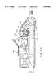
- the suction irrigation system 10(FIG. 1) embodying the invention comprises a pressure liquid unit 11 having a upstanding liquid inlet connector 12 for direct connection to a liquid outlet connector 13 on a conventional irrigation liquid supply IL.
- the irrigation liquid supply ILis a conventional irrigation liquid supply bag 14 and the connector 13 is a conventional luer connector.
- the irrigation liquid bag 14may be conventionally supported by the usual horizontal arm 15 adjustably fixed on the usual standing pole 16, the arm and pole being, for example, of the kind usually employed to support an IV (intravenous) bottle, irrigation liquid bag, or the like.
- the pressure liquid unit 11may be supported from the bag 14 simply by interconnection of the respective connectors 12 and 13.
- additional support meansmay be employed, such as a strap (not shown) fixed in any convenient way to the outside of the pressure liquid unit 11 and to the arm 15.
- the pressure liquid unit 11may be supported by a conventional bracket 18 conventionally clamped at 19 to the pole 16, and encircling the pressure liquid unit 11 snugly, as indicated generally at 20.
- the pressure liquid unit 11pressurizes irrigation liquid tube 23 (FIG. 3) which is flexible and runs at length (for example 6-12 feet) to a handpiece 26 to be gripped and controlled by a user, typically a surgeon or surgical assistant.
- An electric cable 27is comparable in length to the tube 23 and runs with it from the pressure liquid unit 11 to the handpiece 26.
- the cable 27preferably is, for neatness, fixed along the tube 23, for example by longitudinally spaced conventional clips 32 or longitudinal bonding.
- a flexible suction tube 33runs from the handpiece 26 to a conventional suction source SS, such as a conventional hospital operating room suction port.
- the tubes 23 and 33 and cable 27preferably run to the rear end portion 34 of the handpiece 26.
- the handpiece 26 in the embodiment shownhas a rigid tubular tip TP (hereafter described) releasably extending forward from the front end portion 36 thereof for direction toward a surgical site, either directly or through a conventional endoscopic cannula (a fragment of which is schematically indicated at CA in FIG. 1), for performing irrigation and suction removal of debris at a surgical site SU.
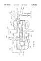
- the pressure liquid unit 11comprises (FIG. 2) a housing generally indicated at 40, in turn comprising an upward opening cup 41, a motor and battery locator 42 and a pump cover 43.
- the cup 41comprises an open top 50 (FIGS. 7-9), a slightly downward tapered side/wall 51 and a generally closed bottom wall 52.
- the bottom wallas an upstepped central motor support drum 53.
- the drumis of circular cross-section.
- An annular, upward facing, battery receiving groove 54is defined radially and coaxially between the cup side wall and drum.
- the battery and motor locator 42(FIGS. 6 and 13) comprises a deck 60 adapted to seat upon the top edge of the cup side wall 51 and substantially close the open top of the cup 41.
- a finned column 61fixedly coaxially depends from the deck 60.
- the columncomprises a hollow tubular wall 59 defining a downward opening recess 62 located coaxially therein and closed at its top by the deck 60.
- the finned exterior of the column 61is defined by a plurality (here eight for example) of circular cross-section grooves 63 extending the length of the column.
- the grooves 63are circumferentially evenly spaced and circumferentially separated by axial, curved cross-section, ridge-like fins 65 radially outwardly extending from the tubular wall 59.
- the radially outermost surface 64 of the columnis somewhat tapered downward in correspondence to the taper of the sidewall 51 of the cup.
- the circular cross-section grooves 63have axes similarly convergent downward toward the central axis of the locator 42 (and thus toward the central axis of the recess 62 and deck 60).
- the grooves 63thus have bottom portions which cut into the recess 62 at the arched notches 66.
- the column 61is sized to depend snugly into the cup 41, with the deck 60 mounted atop the side wall 51 of the cup.
- the bottom of the hollow column 61extends down into the annular groove 54 between the drum and side wall of the cup and the drum 53 is snugly but slidably received upward into the bottom portion of the central recess 62 of the locator.
- the fins 65have their bottom ends 67 (FIGS. 5 and 6) spaced above the bottom wall 52 of the cup 41.
- the locator 42 and cup 41when assembled, are intended to locate therewithin in a circumferential array, plural (here eight) conventional AA batteries B (FIGS. 17 and 18), one in each of the circumferentially distributed grooves 63 of the locator, and a battery powered motor M in the recess 62.
- the motor Mis, in the embodiment shown, shaped generally as a right circular cylinder with coaxially protruding top and bottom bosses 70 and 71.
- a shaft 72extends coaxially up through the top boss 70 and is rotatable with respect thereto. See particularly FIGS. 5 and 21.
- the motor Mis snugly but slidably received up into the recess 62 of the locator 42 with its shaft 72 extending up through a coaxial hole 73 in the deck 60.
- a conventional annular seal 74(FIG. 5) recessed in the top of the deck 60, admits the shaft 72 rotatably upwardly therethrough but prevents liquid leakage therepast downward along the shaft toward the top of boss 70.
- the motor Mis coaxially located in the recess 62 by snug reception of its top boss 70 in a down facing central recess 75 in the deck 60, and its bottom boss 71 in a central opening 76 in the top of the drum 53 (FIGS. 7 and 8).
- the top and sides of the drum 53are cut by three evenly circumferentially spaced pairs of parallel slots 80 communicating with the central opening 76.
- the parallel slots 80 of each pairdefine therebetween a generally L-shaped segment 81 of the drum top and side walls.
- the upper and radially inner ends of the three segments 81are enlarged in cross-section to define corresponding circumferentially spaced rim parts 82 which together define the central opening 76 through the top of the drum.
- the rim parts 82are slightly wedge-shaped, to converge downwardly slightly and thereby tend to center therebetween, in wedging fashion, the bottom boss 71 of the motor M.
- the L-shaped segments 81being separated from the rest of the drum 53 by the flanking slots 80, can resiliently deflect, in the manner of a leaf spring, to snugly grip the bottom boss 71 of the motor M and thereby firmly and fixedly center the motor M coaxially with respect to the cup 41 and locator 42.
- upper contacts 86each comprise a generally straight bight flanked by integral coil compression spring portions 88 of frustoconical profile.
- the profile of each coil spring portions 88tapers downwardly as seen in FIGS. 17 and 18.
- the bight 87 and widened base of each spring portion 88is backed by the underside of the deck 60.
- the coil spring portions 88each are snugly frictionally gripped by the surrounding fins 65 to firmly hold each upper contact 86 axially against the underside of the deck 60.
- the upper contacts 86are easily installed on the column 61 by placing same in registry with the bottom end 67 (FIG. 14) of the corresponding fin 65 and then sliding same there along upwardly into contact with the underside of the deck 60.
- Conductive, flat plate, lower contacts 92each comprise a pair of circumferentially spaced circular disks 93 connected by an integral circumferentially extending strap 94.
- the strap 94is cut in the middle to form respective terminal tabs 94A (FIGS. 17 and 19) for connection of the batteries B, in circuit with the motor M and a switch SW hereafter described.
- the disks 93are respectively fixedly located coaxially with the grooves 63 of the column 61 but are spaced below the column 61 to lie fixedly atop the bottom wall 52 of the cup 41, within the annular groove 54 thereof.
- the disks 93are fixed atop the cup bottom wall 52 by any convenient means.
- the lower contacts 92were installed in a particularly advantageous manner while producing the cup 41 by injection molding.
- the bottom wall 52 of the cup 51is perforated by circumferentially spaced large and small holes 52L and 52S respectively. Same are left by wide and narrow mold pins (not shown) upstanding from a (not shown) mold floor underlying the bottom wall 52 (FIG. 10) of the cup 41 when forming same by molding.
- Eight of the conductive circular disks 93(FIG. 19) were continuously connected in a circle by the straps 94 and supported just above the mold floor by the wide mold pins which produce the larger diameter holes 52L abovementioned.
- the motor Mrequires a nominal 12-volt DC power supply. Accordingly, it is appropriate to provide eight batteries B of the nominal 1 1/2 volt inexpensive, commercially available AA type. In view of their long shelf life and relatively high power storage capability and capability to supply adequate voltage until nearly fully discharged, alkaline batteries are preferred.
- the motor Mhas a pair of electrical contacts MC protruding from the bottom thereof and electrically energizable for rotating the motor shaft.
- circumferential extensions 83 of the slots 80are diametrically opposed in the top of the drum 53 and the electric contacts MC of motor M extend downwardly therethrough for electrical connection in circuit with the batteries B and the switch SW hereafter described.
- Circumferentially spaced ribs 95extend upward along and protrude radially in on the sidewall 51 of the cup 41 and closely radially oppose corresponding ones of the fins 65 of the locator 42. However, the radially outer part of the one of the fins 65 is eliminated, as indicated at 65A in FIG. 13, and its corresponding upstanding cup rib 95 is eliminated, leaving a cable space 96 radially therebetween.
- Electric cable 27(FIG. 5) extends through this cable space 96, substantially vertically along the cup sidewall 51 and exits up through a cable port 101 in the deck 60 near the edge thereof and down through a cable port 102 in the bottom wall 52 of the cup 41.
- the electric cable 27here incorporates two insulated electric wires generally indicated at 103.
- the cover 43(FIGS. 2-6 and 23-26) includes a downwardly opening dome 110, a radially outward extending bottom flange 112 and the inlet connector 12.
- the inlet connector 12takes the form of a hollow spigot upstanding from the top of the dome 110 and, as seen in FIG. 6, provides an irrigation liquid inlet conduit down through the top of the dome 110 and into a pump chamber 113 occupying the upper part of the dome 110.
- a recess 114(FIG. 5) is stepped radially outward slightly from the pump chamber 113 and extends downward therefrom through the bottom of the cover 43.
- the central portion of the deck 60(FIGS.
- a resilient, annular seal 116(FIG. 6) is trapped vertically between axially opposed steps adjacent the top of the recess 114 and plug 115 to seal the bottom of the pump chamber 113.
- a preferably conventional centrifugal pump rotor 117(FIGS. 5 and 6) is fixed coaxially atop the motor shaft 72 in the pump chamber 113. The motor shaft 72 and pump rotor 117 are preferably coaxial with the liquid inlet 12.
- An outlet passage 120extends tangentially from the pump chamber 113 within a tangential extension 121 (FIG. 2) of the dome 110 and has an enlarged diameter outlet recess 122 adapted to fixedly sealingly receive therein the end of the irrigation liquid tube 23 as seen for example in FIG. 2, to pump irrigation liquid into the tube 23.
- a downwardly and radially outwardly opening groove 123which is blind at its radially inner end. With the cover fixed in its proper location atop the locator 42, the blind groove 123 opens downward into the upper cable port 101 in the deck 60 of the locator 42, to route the cable 27 (FIG. 5) upward and radially outward and away from the pressure liquid unit 11 and along the path of the irrigation liquid tube 23, as generally indicated in FIG. 1.
- the cup 41 and locator 42 and cover 43are fixed together, preferably by snap fit connections, as follows.
- the deck 60(FIG. 4) has an upwardly and downwardly thickened rim 124. Radially inboard from the rim 124, the deck 60 is axially punctured by circumferentially extending, circumferentially spaced slots 125 and 126. The slots 125 alternate circumferentially with the slots 126
- Circumferentially spaced, generally L-profile tabs 130each depend slightly bendably from the perimeter edge of the cover 43 and insert downward into a respective slot 125 in the deck 60.
- Each tab 130has a radially outward extending lip 131 (FIGS. 4 and 6) which snaps radially outward under the deck rim 124 to hold the cover 43 fixed downward firmly against the deck 60 of the locator 42.
- the slots 126each have a circumferentially extending step 132 upset radially inward from the rim 124 near the bottom of such slot 126, as indicated for example in FIGS. 4 and 13.
- Circumferentially spaced tabs 133extend up from the sidewall 51 of the cup 41 and are generally L-shaped, each having a shallow radially outward extending lip 134.
- the tabs 133are circumferentially in register with the remaining slots 126 in the locator deck 60.
- the tab lips 134Upon bringing the cup 41 upward coaxially toward the deck 60, the tops of the tabs 133 enter the slots 126.
- the tab lips 134each advance upward past, and are deflected resiliently radially inward by, the corresponding step 132 to snap over such step 132.
- cup 51, locator 42 and cover 43may be of any desired rigid material and manufactured in any desired way it is convenient to mold same each in one piece, of a conventional plastics material.
- a circular, disk-like label of generally rigid materialsuch as cardboard, styrofoam, or the like, fits snugly up into the downward opening recess 55 (FIG. 3) defined by downward extension of the sidewall 51 a short distance below the bottom wall 52.
- Such labelmay be fixed in place as a last step in the assembly operation, by adhesive bonding or by press fit upward into the recess 55 due to the slight downward taper of the cup side wall 51.
- a suitable diskis indicated at 56 in FIGS. 4 and 5.
- the disk 56can be used to cover holes in the bottom wall 52 and wiring between the cable 27 and motor contacts MC and battery lower contacts 93.
- Such disk 56could also be used as a label for describing the product, usage and warnings regarding misuse.
- the spring wire upper contacts 86 and lower contact disks 93are located to connect the eight batteries B in series, as seen in FIG. 16 and as schematically indicated at 8 X B in the FIG. 22 circuit diagram.
- the series battery connection 8 X Bis in turn connected in series loop (through the endmost disks 93) with the motor M (through its contacts MC) and (through the conductors 103 of the cable 27) with the manually actuable switch SW (hereafter described, in the handpiece 26) as shown in FIG. 22.
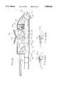
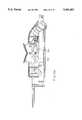
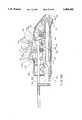
- the handpiece 26comprises an outer shell conveniently defined by opposed concave half shells 200S and 200I located respectively on the suction and irrigation sides of the handpiece, as generally indicated in FIGS. 27-29.
- the edges 201 of the half shell 200Soverlap edges 202 of the half shell 200I (FIGS. 33-38) and are fixed thereto by any convenient means such as conventional snapfit connections 203 and 204 respectively, or by adhesive bonding, or the like.
- An elongate rigid conduit 210extends longitudinally through the lower portion of the shell 200 and has front and rear end portions 211 and 212 which respectively protrude forwardly and rearwardly through front and rear openings 213 and 214 respectively in the substantially radial front wall and in the somewhat downward angled rear end portion 268 of the shell 200 (FIGS. 29 and 57).
- Longitudinally spaced ribs 217 in the half shells 200S and 200Iradially fix conduit 210 therein.
- Transversely extending tabs 20 (FIGS. 44 and 45) fixed on the conduit 210are received in ports 221 (FIGS. 35 and 38) opening toward each other in the half shells 200S and 200I to locate the conduit longitudinally fixedly in the shell 200, as seen for example in FIG. 29.
- annularly ribbed, hollow, tubular suction and irrigation fittings 222I and 222Srigidly connect to the front portion 211 of the rigid conduit 210 inside the shell 200, adjacent the front wall 215 thereof as seen in FIG. 53.
- the fittings 222S and 222Idiverge upwardly and angle rearwardly for fixed securement thereon of respective resiliently pressurably closeable, normally open hoses 224S and 224I (FIG. 29).
- the downward and rearward angled rear opening 214 of the shell 200is normally occupied by an adapter block 225 (FIGS. 42, 43, 53 and 57) fixed into the rear opening 214 (FIG. 53) of the shell 210 during assembly of the two half shells 200S and 200I.
- the adapter block 225(FIGS. 42 and 43) has laterally protruding, partially circumferentially extending, locator ribs 226 fixed thereon. Reception, during assembly of the half shells together, of the ribs 226 snugly between a forward/rearward spaced pair of further ribs 227 (FIGS.
- the adapter blockfurther comprises a laterally spaced pair of generally upwardly and forwardly aimed, externally ribbed fittings 230S and 230I (FIGS. 42 and 43) for receiving thereon, in fixed liquid tight coupled relation, the rear ends of the pinchable hoses 224S and 224I respectively.
- the fittings 230S and 230Iare similar in form to the fittings 222S and 222I above discussed.
- Passages indicated in broken lines at 231extend from the open front of the fittings 230S and 230I rearward through the adapter block and open through the rear end face 232 thereof and are adapted to fixedly and nonleakingly receive, in any conventional manner not shown, the front ends of the suction tube 33 and irrigation liquid tube 23, as indicated in FIGS. 42 and 43.
- the rear end portion 212 of the rigid conduit 210may be closed by a cap 233 (FIG. 32) releasably secured thereon, by any convenient means such as threads.
- the cap 233may be removed to enable insertion forwardly through the conduit 210 of an elongate instrument, or other aid to surgery, whose front end is to be positioned adjacent the surgical site.
- the hollow cylindrical tip TP(FIG. 53) is mountable removably on the front end portion 211 of the rigid conduit 210.
- An O-ring 234 or the like in an annular groove 235 in the conduitsealingly engages the hollow tip TP fixedly to the front end of the conduit 210.
- the rear end portion 212 of the rigid conduit 210passes snugly, but slidably, rearward through a central hole 236 in the adapter block 225 (see FIGS. 42, 43 and 57).
- a transverse shaft 240(FIG. 29) extends across the interior of the shell 200 and has its ends fixed in transversely opposed, tubular bosses 241 (FIGS. 29, 35 and 38).
- the shaft 240is located about mid-height in the shell 200.
- An irrigation pinch lever 242 and a suction pinch lever 243are located on the shaft 240, adjacent the irrigation half shell 200I and suction half shell 200S respectively.
- the pinch leverseach have mid portions pivoted on the shaft 240 and each extends forward and rearward from the shaft.
- the levers 242 and 243each have a through bore 244 for pivoting on the shaft 240 a round edged pinch blade 245 extending from one side thereof adjacent the bore 244, and a pair of tabs 246 and 247 extending from the other side thereof at respective opposite ends thereof.
- the tabs 246are flat and the tabs 247 are domed.
- the pinch levers 242 and 243differ only in that the domed tab 247 of the irrigation pinch lever 242 is somewhat flattened, as seen at 248 (FIG. 41).
- the pinch levers 242 and 243are each assembled on the shaft 240 so that the elongate pinch edge 249 of the blade 245 faces upward but wherein the two pinch blades 245 extend laterally away from each other and toward their respective half shells 200S and 200I.
- the pinch levers 242 and 243are oriented on the shaft 240 such that their respective tabs 247 and 246 are forwardmost (leftwardmost in FIG. 29).
- a resilient metal U-spring 252(FIGS. 29 and 47) of springy sheet metal comprises a U-shaped portion 253 comprising a pair of legs 254 depending from a bight 255. Holes 256 through the lower portion of the legs 254 receive the shaft 240 to pivotly locate the U-spring 252 on the shaft 240 snugly between the pinch levers 242 and 243 and with the bight 255 spaced up above the shaft 240.
- a leaf spring-like arm 257extends rearward and downward from the bight 255. The free end portion 258 of the arm 257 is bent sharply to extend forward and somewhat upward between the legs 254 in spaced relation between the bight 255 and holes 256.
- a coil torsion spring 261(FIG. 29) comprises a central portion 262 wrapped around the shaft 240 between the U-spring legs 254 and from which central portion extends a pair of generally rearwardly extending elongate legs 263I and 263S which are vertically trapped between and resiliently urge vertically apart the rear tabs 246 and 247 of the pinch levers 242 and 243 (FIGS. 52 and 53).
- a rigid, preferably unitary, anvil 270(FIGS. 29 and 39) comprises a fore/aft extending bar 271 locatable between the half shells 200S and 200I (FIG. 29) and spaced above the shaft 240.
- a horizontal shaft 272(FIG. 39) extends toward the half shell 200S.
- the baris widened toward the half shell 200I to form a downwardly stepped, downwardly facing anvil surface 273.
- a hole 274 in the rear end portion of the bar 271is coaxial with the shaft 272 and faces in the opposite direction, namely toward the half shell 200I.
- the bar 271is generally L-shaped, as seen from above, having a leg 275 aimed toward the half shell 200S and terminating in a pin 276.
- the anvil 270is fixed with respect to half shell 200S by entry of the free end of its shaft 272 and the pin 276 into corresponding holes 280 and 281 in, and adjacent the top of, the half shell 200S (FIGS. 29, 37 and 38) and by entry of a pin 282 (FIGS. 34 and 35), fixed within the opposite half shell 200I just below the top thereof, into the opposed hole 274 in the rear portion of the anvil 270. In this manner, the anvil 270 is firmly fixed within the assembled shell 200.
- the anvil 270is spaced above the irrigation pinch lever 242, with its down facing anvil surface 273 directly opposing the upfacing pinch edge 249 of the pinch blade 245 of the irrigation pinch lever 242 (FIGS. 52 and 53) for coaction therewith in pinching and unpinching the irrigation hose 224I which is routed therebetween.
- a further anvilwhich may termed the suction anvil, 283 (FIGS. 29, 37 and 56) is fixed in and preferably formed integrally with the half shell 200S and has a down facing anvil surface 284 underlying the upper shaft hole 280 and at about the same height as the anvil surface 273 cooperating with the irrigation pinch lever 242 above-described.
- the down facing anvil surface 284overlies and cooperates with the upfacing pinch blade edge 249 of the suction pinch lever 243 for pinching and unpinching the suction hose 224S routed therebetween.
- a hand actuable rocker 290(FIG. 29) comprises a generally box-like body 291 (FIG. 50) having parallel upstanding side walls 292 and convexly rounded, upwardly converging front and rear end walls 293.
- the body 291includes a relatively large, generally rectangular, downwardly opening recess 294 (FIG. 57).
- the body 291extends down through an opening 295 in the top of the shell 200.
- the bodyis topped by fixed, preferably integral, divergently angled, front and rear push pads 296 and 297.
- the recess 294 of the rocker 290receives upwardly thereinto the upper portion of the U-shaped part 253 of the U-spring 252, the top of the U-shaped part 253 being spaced below the top of the recess 294 in the rocker.
- the upper (anvil) shaft 272(FIGS. 29 and 57) extends laterally through holes 300 in the sides 292 (FIG. 50) of the rocker 290.
- the anvil shaft 272also extends through aligned holes 301 in the upper parts of the U-spring legs 254 (FIG. 56).
- the U-spring 272is substantially fixed in place with respect to the shell 200 by passage of the upper and lower shafts 272 and 240 therethrough and the rocker 290 (FIG. 57) is pivoted on the anvil shaft 272 for rocking forwardly and rearwardly (clockwise or counterclockwise in the drawing) about the anvil shaft 272.
- the forwardly and upwardly angled front end portion 258 of the U-spring 252lies within the downward opening recess 294 of the rocker 290 and at its forward extremity (left extremity in FIG. 57) is fixed to the front wall 293 of the rocker 292 by any convenient means, such as by being molded integrally with the rocker 290.
- the U-spring 252is arranged to resiliently urge the rocker 290 to its central, horizontal position shown in FIG. 57 and to resiliently resist, but permit, forward and rearward (in FIG. 57 counterclockwise and clockwise) rocking of the rocker 290 by the user.
- the rocker 290is pivotable forward (counterclockwise in FIG. 57) to push the bottom edge of its front wall 293 down against irrigation lever front tab 247, correspondingly counterclockwise rotate the irrigation pinch lever 242, cause its pinch blade 245 to drop away from the corresponding irrigation hose 224I, and thus open the irrigation hose 224I, as in the transition from FIG. 53A to FIG. 53B.
- the rocker 290is pivotable rearward (clockwise in FIG.
- the electrical switch SW of the handpiece 26is formed by a switch spring 310 and a Z-spring 311, seen in FIGS. 48 and 49 respectively. Both are formed of resiliently deflectable, electrically conductive, sheet metal.
- the switch spring 310comprises a base plate 312 having a free end provided with gripper tabs 313 reflexly bent, a generally L profile female electric terminal 314 and a switch contact arm 315.
- the Z-spring 311(FIG. 49) comprises a base plate 320 whose free end is provided with gripper tabs 321, a generally L-shaped planar electric terminal 322, and a generally Z-shaped switch contact 323.
- the half shell 200S(FIGS.
- the tubular boss 241to the rear of the tubular boss 241, comprises rear and front lateral recesses 325 and 324 respectively which open toward the opposite half shell 200I and are shaped to receive the gripper tab equipped, free end portions of the base plates 312 and 320 of the switch spring 310 and Z-spring 311, respectively.
- the switch spring and Z-springare oriented so that their electric terminals 314 and 322 extend rearwardly (FIG. 57) and so that their switch contacts 315 and 323 respectively extend upwardly and forwardly.
- the top of the switch contact 323is normally spaced slightly in front of the top portion of the switch contact 315. See also FIGS. 51 and 52.
- a preferably integral switch actuator foot 326(FIG. 53) arranged so that forward (counterclockwise) tilting of the rocker 290 not only opens the irrigation tube 224 by dropping the pinch blade 245 (in the transition from FIG. 53A to FIG. 53B), but also pivots the foot 326 (FIG. 59) upward and rearward, to push the switch contact 323 of the Z spring 311 rearwardly into electrical contact with the switch contact 315 of the switch spring 310.
- rocking the rocker 290 rearwarddrops the pinch blade 245 of the suction pinch lever 243 to open the suction tube 224 (in the transition from FIG. 56A to 56B) to allow suction flow from the tip back to a suction source SS.
- a guard pin 330(FIG. 29) has its square cross-section, elongate shank 331 inserted rearwardly through a hole 332 in front wall 333 of the shell (FIGS. 27-29).
- the guard pin shank 331(FIG. 58) extends through the front wall hole 332 rearward into the shell 200 snugly under the front and rear walls 293 of the rocker 290 to positively prevent pivoting of the rocker 290 and thereby preventing closure of the electric switch contacts 315 and 323.
- FIGS. 53-58show the parts in this storage position, with the guard pin shank 331 in solid line in FIG. 58 and in dotted line (to better show parts behind it in the drawings) in FIGS. 53-57.
- a shield 335depends from the shank 331 near the ring 334 to partly cover and protect, during storage and shipping, the open front end of the conduit 210.
- the guard pin 330When the apparatus is ready for use, the guard pin 330 is withdrawn from the handpiece by forward pull on a finger ring 334 (FIG. 29) fixed on the front end of the shank 331.
- the remaining primary parts of the handpieceare formed of a suitable rigid material, by any convenient means, such as molding of a rigid plastics material.
- the inlet connector 12 of the pumping unit 11is inserted in the corresponding fitting of an irrigation liquid supply (e.g. bag) IL and the pumping unit 11 is supported therebelow by means above discussed.
- the guard pin 330is pulled from the handpiece 26.
- the tip TP of the handpiece 26is inserted into a surgical site SU in a patient, e.g. through a cannula CA previously inserted thereinto.
- the disclosed suction irrigation system 10is totally disposable and manufacturable at relatively low cost. Upon insertion of the inlet flow connector 12 into the irrigation liquid source IL, and pulling out of the guard pin 330, the system 10 is ready for immediate use.
- the systemprovides a high flow rate of irrigation liquid (higher than usual for a disposable system). The flow rate is steady so as not to make tissue jump at the surgical site, as might a pulsed irrigation system.
- Location of motor, pump and batteries remotely from the handpiece, adjacent the irrigation liquid source ILnot only provides for substantially instantaneous priming of the pump but also permits a compact, very lightweight, and hence readily maneuverable handpiece 26.
- the connector 13(FIGS. 1 and 1A) on the liquid supply container 14 was a conventional luer female fitting.
- the liquid inlet connector 12was provided with an annular rib 12A (FIGS. 1, 2 and 4-6) adjacent its upper end to snapfit into the bag fitting 13 forcibly enough to support the weight of the pumping unit 11 (and its trailing hose 23 and cable 27) pendently from the container 14, yet allow the pumping unit 11 to be intentionally disconnected from the container 14 by pulling same apart more forcibly.
- the pumping unit 11 with its trailing hose 23 and cable 27can be entirely supported pendently from the liquid supply container 14 by connection of its hollow spike 12 to the container fitting 13, or can instead be supported by separate means, exemplified by the bracket 18 of FIG. 1.
Landscapes
- Health & Medical Sciences (AREA)
- Heart & Thoracic Surgery (AREA)
- Life Sciences & Earth Sciences (AREA)
- Biomedical Technology (AREA)
- Anesthesiology (AREA)
- Hematology (AREA)
- Engineering & Computer Science (AREA)
- Animal Behavior & Ethology (AREA)
- General Health & Medical Sciences (AREA)
- Public Health (AREA)
- Veterinary Medicine (AREA)
- Vascular Medicine (AREA)
- Pulmonology (AREA)
- Endoscopes (AREA)
Abstract
Description
Claims (18)
Priority Applications (4)
| Application Number | Priority Date | Filing Date | Title |
|---|---|---|---|
| US08/176,130US5484402A (en) | 1993-12-30 | 1993-12-30 | Surgical suction irrigator |
| US08/769,428US6213970B1 (en) | 1993-12-30 | 1996-12-19 | Surgical suction irrigation |
| US09/676,517US6623445B1 (en) | 1993-12-30 | 2000-10-02 | Surgical suction irrigator |
| US10/648,693US7297133B2 (en) | 1993-12-30 | 2003-08-26 | Surgical suction irrigator |
Applications Claiming Priority (1)
| Application Number | Priority Date | Filing Date | Title |
|---|---|---|---|
| US08/176,130US5484402A (en) | 1993-12-30 | 1993-12-30 | Surgical suction irrigator |
Related Child Applications (1)
| Application Number | Title | Priority Date | Filing Date |
|---|---|---|---|
| US50270895AContinuation-In-Part | 1993-12-30 | 1995-07-14 |
Publications (1)
| Publication Number | Publication Date |
|---|---|
| US5484402Atrue US5484402A (en) | 1996-01-16 |
Family
ID=22643101
Family Applications (1)
| Application Number | Title | Priority Date | Filing Date |
|---|---|---|---|
| US08/176,130Expired - LifetimeUS5484402A (en) | 1993-12-30 | 1993-12-30 | Surgical suction irrigator |
Country Status (1)
| Country | Link |
|---|---|
| US (1) | US5484402A (en) |
Cited By (97)
| Publication number | Priority date | Publication date | Assignee | Title |
|---|---|---|---|---|
| US5630908A (en)* | 1993-09-23 | 1997-05-20 | Valmet Corporation | Method in the operation of a doctor in a paper/board machine |
| USD380544S (en)* | 1996-03-08 | 1997-07-01 | Conmed Corporation | Manual control for a laparoscopic instrument |
| US5647852A (en)* | 1995-01-31 | 1997-07-15 | Zimmer, Inc. | Lavage system including a cassette assembly |
| WO1998003214A1 (en)* | 1996-07-19 | 1998-01-29 | C.R. Bard, Inc. | Battery powered surgical irrigator |
| US5792167A (en)* | 1996-09-13 | 1998-08-11 | Stryker Corporation | Surgical irrigation pump and tool system |
| US5810770A (en)* | 1996-12-13 | 1998-09-22 | Stryker Corporation | Fluid management pump system for surgical procedures |
| US5941851A (en)* | 1996-07-12 | 1999-08-24 | C.R. Bard, Inc. | Pulsed lavage handpiece with improved handle |
| US6022329A (en) | 1993-04-19 | 2000-02-08 | Stryker Corporation | Irrigation handpiece with built in pulsing pump |
| US6086554A (en)* | 1998-06-04 | 2000-07-11 | Cabot Technology Corporation | Surgical suction/irrigation probe assembly with a rotatable adaptor |
| US6099494A (en)* | 1997-08-20 | 2000-08-08 | Stryker Corporation | Pulsed irrigator useful for surgical and medical procedures |
| US6162194A (en)* | 1998-05-20 | 2000-12-19 | Apollo Camera, Llc | Surgical irrigation apparatus and methods for use |
| US6176847B1 (en) | 1999-05-14 | 2001-01-23 | Circon Corporation | Surgical irrigation system incorporating flow sensor device |
| US6213970B1 (en)* | 1993-12-30 | 2001-04-10 | Stryker Corporation | Surgical suction irrigation |
| WO2001051105A2 (en) | 2000-01-11 | 2001-07-19 | C.R. Bard, Inc. | Electrically powered surgical irrigator |
| EP1086713A3 (en)* | 1999-09-24 | 2002-01-02 | Tyco Healthcare Group Lp | Irrigation system for endoscopic surgery |
| US6342061B1 (en) | 1996-09-13 | 2002-01-29 | Barry J. Kauker | Surgical tool with integrated channel for irrigation |
| WO2002024253A2 (en) | 2000-09-22 | 2002-03-28 | C.R. Bard, Inc. | Electrically powered surgical irrigator |
| WO2002024252A2 (en) | 2000-09-22 | 2002-03-28 | C.R. Bard, Inc. | Surgical irrigation system |
| USD462437S1 (en) | 1997-04-14 | 2002-09-03 | Baxter International Inc. | Manually operable irrigation surgical instrument |
| US6461323B2 (en) | 2000-05-03 | 2002-10-08 | Reginald H. Fowler | Surgical system pump with flow sensor and method therefor |
| US6517531B2 (en) | 2001-04-27 | 2003-02-11 | Scimed Life Systems, Inc. | Medical suction device |
| US6527743B1 (en) | 2000-05-03 | 2003-03-04 | Ethicon Endo-Surgery, Inc. | Surgical system pump and method therefor |
| US20030109826A1 (en)* | 2000-05-03 | 2003-06-12 | Conmed Corp. | Surgical system pump and method therefor |
| US6585720B2 (en)* | 1996-03-15 | 2003-07-01 | Colocare Holdings Pty Ltd | Colostomy pump and aid |
| WO2002092149A3 (en)* | 2001-05-16 | 2003-09-25 | Acmi Corp | Fluid delivery system for use with a surgical pumping unit |
| US20030212363A1 (en)* | 2001-04-16 | 2003-11-13 | Surgicon, Inc. | Surgical irrigation apparatus and methods for use |
| US6652488B1 (en) | 2000-09-11 | 2003-11-25 | Stryker Corporation | Surgical suction irrigator |
| US20030236508A1 (en)* | 2002-06-24 | 2003-12-25 | Cull Laurence J. | Adjustable fluid flow resistor cassette |
| US6746419B1 (en) | 1993-04-19 | 2004-06-08 | Stryker Corporation | Irrigation handpiece with built in pulsing pump |
| US20040199200A1 (en)* | 2003-04-07 | 2004-10-07 | Scimed Life Systems, Inc. | Beaded basket retrieval device |
| US6869439B2 (en) | 1996-09-19 | 2005-03-22 | United States Surgical Corporation | Ultrasonic dissector |
| US20050113794A1 (en)* | 2003-09-22 | 2005-05-26 | Rucinski Paul J. | Novel wound irrigation device and method |
| US20050143769A1 (en)* | 2002-08-19 | 2005-06-30 | White Jeffrey S. | Ultrasonic dissector |
| US6958058B1 (en) | 2001-05-18 | 2005-10-25 | Medsafe Inc. | Methods and devices for pumping fluid and performing surgical procedures |
| US20060122576A1 (en)* | 2003-10-22 | 2006-06-08 | Khalid Raja | Fluid delivery system for use with a surgical pumping unit |
| US20060224129A1 (en)* | 1998-12-07 | 2006-10-05 | Beasley Jim C | Septum including at least one identifiable feature, access ports including same, and related methods |
| US20060247584A1 (en)* | 2005-03-04 | 2006-11-02 | C.R. Bard, Inc. | Access port identification systems and methods |
| US20060264898A1 (en)* | 2005-04-27 | 2006-11-23 | Beasley Jim C | Infusion apparatuses and related methods |
| US20070005002A1 (en)* | 2005-06-30 | 2007-01-04 | Intuitive Surgical Inc. | Robotic surgical instruments for irrigation, aspiration, and blowing |
| US20070233017A1 (en)* | 2006-10-18 | 2007-10-04 | Medical Components, Inc. | Venous access port assembly with radiopaque indicia |
| US20070233003A1 (en)* | 2005-12-14 | 2007-10-04 | Radgowski Todd J | Surgical irrigation system |
| US20070239113A1 (en)* | 2006-04-06 | 2007-10-11 | Reznik Alan M | Arthroscopic fluid control device |
| US20080167527A1 (en)* | 2007-01-09 | 2008-07-10 | Slenker Dale E | Surgical systems and methods for biofilm removal, including a sheath for use therewith |
| USD574950S1 (en)* | 2007-09-07 | 2008-08-12 | C.R. Bard, Inc. | Implantable port device |
| US20080319399A1 (en)* | 2007-06-20 | 2008-12-25 | Medical Components, Inc. | Venous access port with molded and/or radiopaque indicia |
| US20090024024A1 (en)* | 2007-07-19 | 2009-01-22 | Innovative Medical Devices, Llc | Venous Access Port Assembly with X-Ray Discernable Indicia |
| US20090174558A1 (en)* | 2004-03-05 | 2009-07-09 | White Russell W | Athletic Monitoring System And Method |
| US20100049119A1 (en)* | 2008-08-22 | 2010-02-25 | Norman Gerould W | Surgical fluid management system |
| US20100069743A1 (en)* | 2005-03-04 | 2010-03-18 | C. R. Bard, Inc. | Systems and methods for identifying an access port |
| USD612479S1 (en) | 2007-09-07 | 2010-03-23 | C. R. Bard, Inc. | Implantable port device |
| US20100324473A1 (en)* | 2006-04-06 | 2010-12-23 | Reznik Alan M | Arthroscopic fluid control device and method for controlling fluid flow in arthroscopic procedures |
| WO2010016089A3 (en)* | 2008-08-08 | 2011-01-06 | Ab Medica S.P.A. | Irrigation and suction system, in particular for laparoscopic surgery |
| US7867196B1 (en) | 2005-09-13 | 2011-01-11 | Medsafe, Llc | Pump and method having reduced pressure and friction for providing fluid, especially for surgical procedures |
| US7947022B2 (en) | 2005-03-04 | 2011-05-24 | C. R. Bard, Inc. | Access port identification systems and methods |
| FR2955242A1 (en)* | 2010-01-19 | 2011-07-22 | Axess Vision Technology | MEDICAL ENDOSCOPE COMPRISING A CONSUMABLE INSTRUMENT WITH CIRCUIT CIRCUIT OF A FLUID |
| USD642260S1 (en)* | 2007-03-07 | 2011-07-26 | William Hendricks | Bottle for delivering nutrients to an enteral feeding tube |
| WO2011091075A1 (en) | 2010-01-19 | 2011-07-28 | Jeffrey Alan Klein | Sterile disposable remote pneumatic actuators |
| US8021324B2 (en) | 2007-07-19 | 2011-09-20 | Medical Components, Inc. | Venous access port assembly with X-ray discernable indicia |
| US8029482B2 (en) | 2005-03-04 | 2011-10-04 | C. R. Bard, Inc. | Systems and methods for radiographically identifying an access port |
| US8206349B2 (en) | 2007-03-01 | 2012-06-26 | Medtronic Xomed, Inc. | Systems and methods for biofilm removal, including a biofilm removal endoscope for use therewith |
| WO2012156959A1 (en)* | 2011-05-16 | 2012-11-22 | Cork Institute Of Technology | A fluid removal and delivery apparatus |
| USD676955S1 (en) | 2010-12-30 | 2013-02-26 | C. R. Bard, Inc. | Implantable access port |
| US8429788B1 (en) | 2004-09-17 | 2013-04-30 | Creative Marketing Strategies Inc. | Liquid separation device for suction nozzles |
| USD682416S1 (en) | 2010-12-30 | 2013-05-14 | C. R. Bard, Inc. | Implantable access port |
| US8641676B2 (en) | 2005-04-27 | 2014-02-04 | C. R. Bard, Inc. | Infusion apparatuses and methods of use |
| US20140046249A1 (en)* | 2006-12-20 | 2014-02-13 | Linvatec Corporation | Dual pump arthroscopic irrigation/aspiration system with outflow control |
| US8715244B2 (en) | 2009-07-07 | 2014-05-06 | C. R. Bard, Inc. | Extensible internal bolster for a medical device |
| US8915842B2 (en) | 2008-07-14 | 2014-12-23 | Ethicon Endo-Surgery, Inc. | Methods and devices for maintaining visibility and providing irrigation and/or suction during surgical procedures |
| US8932271B2 (en) | 2008-11-13 | 2015-01-13 | C. R. Bard, Inc. | Implantable medical devices including septum-based indicators |
| US9079004B2 (en) | 2009-11-17 | 2015-07-14 | C. R. Bard, Inc. | Overmolded access port including anchoring and identification features |
| US20150351954A1 (en)* | 2013-02-05 | 2015-12-10 | Centre Hospitalier Regional Universitaire De Lille | Device enabling flow of food bolus between two stomas |
| CN105163772A (en)* | 2013-06-03 | 2015-12-16 | 顿特斯普雷Ih公司 | Cylindrical collapsible container |
| EP1977776B1 (en) | 1999-11-29 | 2016-02-10 | KCI Medical Resources | Wound treatment apparatus |
| US9265912B2 (en) | 2006-11-08 | 2016-02-23 | C. R. Bard, Inc. | Indicia informative of characteristics of insertable medical devices |
| US9326665B2 (en) | 2007-01-09 | 2016-05-03 | Medtronic Xomed, Inc. | Surgical instrument, system, and method for biofilm removal |
| USD758590S1 (en)* | 2014-11-26 | 2016-06-07 | Baylis Medical Company Inc. | Switch box |
| US9474888B2 (en) | 2005-03-04 | 2016-10-25 | C. R. Bard, Inc. | Implantable access port including a sandwiched radiopaque insert |
| US9579496B2 (en) | 2007-11-07 | 2017-02-28 | C. R. Bard, Inc. | Radiopaque and septum-based indicators for a multi-lumen implantable port |
| US9642986B2 (en) | 2006-11-08 | 2017-05-09 | C. R. Bard, Inc. | Resource information key for an insertable medical device |
| US9827367B2 (en) | 2008-04-29 | 2017-11-28 | Medtronic Xomed, Inc. | Surgical instrument, system, and method for frontal sinus irrigation |
| US10098703B2 (en) | 2011-08-16 | 2018-10-16 | Intuitive Surgical Operations, Inc. | Surgical instrument with commonly actuated robotic and manual features |
| USD831819S1 (en) | 2016-01-22 | 2018-10-23 | Medline Industries, Inc. | Irrigator |
| US10220123B2 (en) | 2010-08-25 | 2019-03-05 | Camodo, Llc | Hand held irrigation and suction tool |
| US10271716B2 (en) | 2008-06-27 | 2019-04-30 | C.R. Bard, Inc. | Endoscopic vacuum controller |
| US10286141B2 (en) | 2014-01-31 | 2019-05-14 | Camodo, Llc | Combination suction and irrigation tool |
| US10307581B2 (en) | 2005-04-27 | 2019-06-04 | C. R. Bard, Inc. | Reinforced septum for an implantable medical device |
| US11020194B2 (en) | 2017-11-02 | 2021-06-01 | National Chiao Tung University | Minimally invasive surgical instruments with terminal steerable mechanism |
| US11324526B2 (en) | 2018-02-02 | 2022-05-10 | Calyxo, Inc. | Devices and methods for minimally invasive kidney stone removal by combined aspiration and irrigation |
| CN114929092A (en)* | 2019-10-28 | 2022-08-19 | 史赛克公司 | Systems and methods for peristaltic endoscope cleaning |
| US20230044805A1 (en)* | 2020-01-08 | 2023-02-09 | Spoke Medical Limited | Fluid transfer device |
| US20230277750A1 (en)* | 2022-03-01 | 2023-09-07 | Br Surgical, Llc | Medical implement for providing suction and irrigation |
| US11844544B2 (en) | 2021-08-25 | 2023-12-19 | Medtronic Ps Medical, Inc. | Irrigation devices in debridement systems |
| US11890443B2 (en) | 2008-11-13 | 2024-02-06 | C. R. Bard, Inc. | Implantable medical devices including septum-based indicators |
| US12004724B2 (en) | 2021-05-06 | 2024-06-11 | Medtronic Xomed, Inc. | Endoscope cleaning system |
| US12256989B2 (en) | 2022-09-29 | 2025-03-25 | Calyxo, Inc. | Tool guiding device for kidney stone treatment apparatus |
| US12329399B2 (en) | 2022-03-02 | 2025-06-17 | Calyxo, Inc. | Kidney stone treatment system |
| US12403236B2 (en) | 2020-06-02 | 2025-09-02 | Stryker Corporation | Modular, multi-specialty fluid pump |
Citations (14)
| Publication number | Priority date | Publication date | Assignee | Title |
|---|---|---|---|---|
| US3861383A (en)* | 1973-09-24 | 1975-01-21 | Leslie J Kovach | Skin massaging instrument |
| US4493694A (en)* | 1980-10-17 | 1985-01-15 | Cooper Lasersonics, Inc. | Surgical pre-aspirator |
| US4935005A (en)* | 1985-06-05 | 1990-06-19 | Nestle, S.A. | Opthalmic fluid flow control system |
| US4982739A (en)* | 1989-02-06 | 1991-01-08 | Board Of Regents For The Univeristy Of Oklahoma | Biosample aspirator |
| US5120305A (en)* | 1990-05-11 | 1992-06-09 | Boehringer Laboratories | Method and apparatus for delivering or withdrawing fluids |
| US5142723A (en)* | 1990-11-09 | 1992-09-01 | L. Paul Lustig | Tooth cleaning apparatus having powered brush and spray |
| WO1992021388A1 (en)* | 1991-05-29 | 1992-12-10 | Fundação Adib Jatene | Pump |
| US5170779A (en)* | 1991-01-22 | 1992-12-15 | Ginsberg Irwin A | Automated ear cleansing device |
| US5186714A (en)* | 1992-05-18 | 1993-02-16 | Yab Revo-Tech Inc. | Multifunctional surgical instrument |
| US5197460A (en)* | 1989-06-20 | 1993-03-30 | Ricoh Elemex Corporation | Mouth cavity sanitary device |
| US5203769A (en)* | 1989-11-06 | 1993-04-20 | Mectra Labs, Inc. | Medical device valving mechanism |
| US5224929A (en)* | 1990-12-21 | 1993-07-06 | C. R. Bard, Inc. | Irrigation/aspiration cannula and valve assembly |
| US5295956A (en)* | 1992-10-09 | 1994-03-22 | Symbiosis Corporation | Endoscopic suction instrument having variable suction strength capabilities |
| US5322503A (en)* | 1991-10-18 | 1994-06-21 | Desai Ashvin H | Endoscopic surgical instrument |
- 1993
- 1993-12-30USUS08/176,130patent/US5484402A/ennot_activeExpired - Lifetime
Patent Citations (14)
| Publication number | Priority date | Publication date | Assignee | Title |
|---|---|---|---|---|
| US3861383A (en)* | 1973-09-24 | 1975-01-21 | Leslie J Kovach | Skin massaging instrument |
| US4493694A (en)* | 1980-10-17 | 1985-01-15 | Cooper Lasersonics, Inc. | Surgical pre-aspirator |
| US4935005A (en)* | 1985-06-05 | 1990-06-19 | Nestle, S.A. | Opthalmic fluid flow control system |
| US4982739A (en)* | 1989-02-06 | 1991-01-08 | Board Of Regents For The Univeristy Of Oklahoma | Biosample aspirator |
| US5197460A (en)* | 1989-06-20 | 1993-03-30 | Ricoh Elemex Corporation | Mouth cavity sanitary device |
| US5203769A (en)* | 1989-11-06 | 1993-04-20 | Mectra Labs, Inc. | Medical device valving mechanism |
| US5120305A (en)* | 1990-05-11 | 1992-06-09 | Boehringer Laboratories | Method and apparatus for delivering or withdrawing fluids |
| US5142723A (en)* | 1990-11-09 | 1992-09-01 | L. Paul Lustig | Tooth cleaning apparatus having powered brush and spray |
| US5224929A (en)* | 1990-12-21 | 1993-07-06 | C. R. Bard, Inc. | Irrigation/aspiration cannula and valve assembly |
| US5170779A (en)* | 1991-01-22 | 1992-12-15 | Ginsberg Irwin A | Automated ear cleansing device |
| WO1992021388A1 (en)* | 1991-05-29 | 1992-12-10 | Fundação Adib Jatene | Pump |
| US5322503A (en)* | 1991-10-18 | 1994-06-21 | Desai Ashvin H | Endoscopic surgical instrument |
| US5186714A (en)* | 1992-05-18 | 1993-02-16 | Yab Revo-Tech Inc. | Multifunctional surgical instrument |
| US5295956A (en)* | 1992-10-09 | 1994-03-22 | Symbiosis Corporation | Endoscopic suction instrument having variable suction strength capabilities |
Cited By (229)
| Publication number | Priority date | Publication date | Assignee | Title |
|---|---|---|---|---|
| US6022329A (en) | 1993-04-19 | 2000-02-08 | Stryker Corporation | Irrigation handpiece with built in pulsing pump |
| US20040210186A1 (en)* | 1993-04-19 | 2004-10-21 | Stryker Corporation. | Irrigation handpiece with built in pulsing pump |
| US7144383B2 (en) | 1993-04-19 | 2006-12-05 | Stryker Corporation | Surgical/medical irrigating handpiece with variable speed pump, integrated suction and battery pack |
| US20070149918A1 (en)* | 1993-04-19 | 2007-06-28 | Arnett Jeffery D | Medical/surgical irrigator with a tip through which irrigation fluid is discharged and a suction is drawn, a variable rate pulse pump for discharging the irrigation fluid and a seperate battery pack for powering the pump |
| US6746419B1 (en) | 1993-04-19 | 2004-06-08 | Stryker Corporation | Irrigation handpiece with built in pulsing pump |
| US5630908A (en)* | 1993-09-23 | 1997-05-20 | Valmet Corporation | Method in the operation of a doctor in a paper/board machine |
| US7297133B2 (en) | 1993-12-30 | 2007-11-20 | Stryker Corporation | Surgical suction irrigator |
| US6213970B1 (en)* | 1993-12-30 | 2001-04-10 | Stryker Corporation | Surgical suction irrigation |
| US20050075600A1 (en)* | 1993-12-30 | 2005-04-07 | Stryker Corporation | Surgical suction irrigator |
| US6623445B1 (en) | 1993-12-30 | 2003-09-23 | Stryker Corporation | Surgical suction irrigator |
| US5647852A (en)* | 1995-01-31 | 1997-07-15 | Zimmer, Inc. | Lavage system including a cassette assembly |
| USD380544S (en)* | 1996-03-08 | 1997-07-01 | Conmed Corporation | Manual control for a laparoscopic instrument |
| US6585720B2 (en)* | 1996-03-15 | 2003-07-01 | Colocare Holdings Pty Ltd | Colostomy pump and aid |
| US5941851A (en)* | 1996-07-12 | 1999-08-24 | C.R. Bard, Inc. | Pulsed lavage handpiece with improved handle |
| WO1998003214A1 (en)* | 1996-07-19 | 1998-01-29 | C.R. Bard, Inc. | Battery powered surgical irrigator |
| US5807313A (en)* | 1996-07-19 | 1998-09-15 | C. R. Bard, Inc. | Battery powered surgical irrigator |
| US6007556A (en)* | 1996-09-13 | 1999-12-28 | Stryker Corporation | Surgical irrigation pump and tool system |
| US6342061B1 (en) | 1996-09-13 | 2002-01-29 | Barry J. Kauker | Surgical tool with integrated channel for irrigation |
| US5928257A (en)* | 1996-09-13 | 1999-07-27 | Stryker Corporation | Surgical irrigation pump and tool system |
| US5792167A (en)* | 1996-09-13 | 1998-08-11 | Stryker Corporation | Surgical irrigation pump and tool system |
| US6869439B2 (en) | 1996-09-19 | 2005-03-22 | United States Surgical Corporation | Ultrasonic dissector |
| US20080243160A1 (en)* | 1996-09-19 | 2008-10-02 | White Jeffrey S | Ultrasonic Dissector |
| US5810770A (en)* | 1996-12-13 | 1998-09-22 | Stryker Corporation | Fluid management pump system for surgical procedures |
| USD462437S1 (en) | 1997-04-14 | 2002-09-03 | Baxter International Inc. | Manually operable irrigation surgical instrument |
| US6179807B1 (en) | 1997-08-20 | 2001-01-30 | Stryker Corporation | Surgical/medical irrigator with removable tip and integrated suction conduit |
| US7153287B2 (en) | 1997-08-20 | 2006-12-26 | Stryker Corporation | Surgical/medical irrigator with removable splash shield |
| US6471668B2 (en) | 1997-08-20 | 2002-10-29 | Stryker Corporation | Surgical/medical irrigator with adjustable nozzle |
| US6352527B1 (en) | 1997-08-20 | 2002-03-05 | Stryker Corporation | Surgical/medical irrigator with rechargeable battery pack |
| US20030036723A1 (en)* | 1997-08-20 | 2003-02-20 | Stryker Corporation | Surgical/medical irrigator with removable splash shield |
| US6099494A (en)* | 1997-08-20 | 2000-08-08 | Stryker Corporation | Pulsed irrigator useful for surgical and medical procedures |
| US6162194A (en)* | 1998-05-20 | 2000-12-19 | Apollo Camera, Llc | Surgical irrigation apparatus and methods for use |
| US6086554A (en)* | 1998-06-04 | 2000-07-11 | Cabot Technology Corporation | Surgical suction/irrigation probe assembly with a rotatable adaptor |
| US8608713B2 (en) | 1998-12-07 | 2013-12-17 | C. R. Bard, Inc. | Septum feature for identification of an access port |
| US8177762B2 (en) | 1998-12-07 | 2012-05-15 | C. R. Bard, Inc. | Septum including at least one identifiable feature, access ports including same, and related methods |
| US20060224129A1 (en)* | 1998-12-07 | 2006-10-05 | Beasley Jim C | Septum including at least one identifiable feature, access ports including same, and related methods |
| US6176847B1 (en) | 1999-05-14 | 2001-01-23 | Circon Corporation | Surgical irrigation system incorporating flow sensor device |
| EP1086713A3 (en)* | 1999-09-24 | 2002-01-02 | Tyco Healthcare Group Lp | Irrigation system for endoscopic surgery |
| AU776352B2 (en)* | 1999-09-24 | 2004-09-02 | Covidien Lp | Irrigation system for endoscopic surgery |
| EP1977776B1 (en) | 1999-11-29 | 2016-02-10 | KCI Medical Resources | Wound treatment apparatus |
| WO2001051105A3 (en)* | 2000-01-11 | 2001-12-20 | Bard Inc C R | Electrically powered surgical irrigator |
| WO2001051105A2 (en) | 2000-01-11 | 2001-07-19 | C.R. Bard, Inc. | Electrically powered surgical irrigator |
| US6685667B1 (en) | 2000-01-11 | 2004-02-03 | C. R. Bard, Inc. | Electrically powered surgical irrigator |
| US6461323B2 (en) | 2000-05-03 | 2002-10-08 | Reginald H. Fowler | Surgical system pump with flow sensor and method therefor |
| US6635031B2 (en) | 2000-05-03 | 2003-10-21 | Ethicon Endo-Surgery, Inc. | Surgical system pump and method therefor |
| US6527743B1 (en) | 2000-05-03 | 2003-03-04 | Ethicon Endo-Surgery, Inc. | Surgical system pump and method therefor |
| US20030109826A1 (en)* | 2000-05-03 | 2003-06-12 | Conmed Corp. | Surgical system pump and method therefor |
| US6899697B2 (en) | 2000-05-03 | 2005-05-31 | Conmed Corp. | Surgical system pump and method therefor |
| US20040158203A1 (en)* | 2000-09-11 | 2004-08-12 | Stryker Corporation | Surgical suction irrigator |
| US7481791B2 (en)* | 2000-09-11 | 2009-01-27 | Stryker Corporation | Surgical suction irrigator |
| US6652488B1 (en) | 2000-09-11 | 2003-11-25 | Stryker Corporation | Surgical suction irrigator |
| US20040097872A1 (en)* | 2000-09-22 | 2004-05-20 | Michael Delk | Surgical irrigation system |
| US7632248B2 (en) | 2000-09-22 | 2009-12-15 | C.R. Bard, Inc. | Surgical irrigation system |
| WO2002024252A2 (en) | 2000-09-22 | 2002-03-28 | C.R. Bard, Inc. | Surgical irrigation system |
| WO2002024252A3 (en)* | 2000-09-22 | 2003-05-30 | Bard Inc C R | Surgical irrigation system |
| WO2002024253A3 (en)* | 2000-09-22 | 2003-03-06 | Bard Inc C R | Electrically powered surgical irrigator |
| WO2002024253A2 (en) | 2000-09-22 | 2002-03-28 | C.R. Bard, Inc. | Electrically powered surgical irrigator |
| US20030212363A1 (en)* | 2001-04-16 | 2003-11-13 | Surgicon, Inc. | Surgical irrigation apparatus and methods for use |
| US8100892B2 (en) | 2001-04-27 | 2012-01-24 | Boston Scientific Scimed, Inc. | Medical suction device |
| US7540868B2 (en) | 2001-04-27 | 2009-06-02 | Boston Scientific Scimed, Inc. | Medical suction device |
| US20030078566A1 (en)* | 2001-04-27 | 2003-04-24 | Scimed Life Systems, Inc. | Medical suction device |
| US8672928B2 (en) | 2001-04-27 | 2014-03-18 | Boston Scientific Scimed, Inc. | Medical suction device |
| US6517531B2 (en) | 2001-04-27 | 2003-02-11 | Scimed Life Systems, Inc. | Medical suction device |
| WO2002092149A3 (en)* | 2001-05-16 | 2003-09-25 | Acmi Corp | Fluid delivery system for use with a surgical pumping unit |
| US6958058B1 (en) | 2001-05-18 | 2005-10-25 | Medsafe Inc. | Methods and devices for pumping fluid and performing surgical procedures |
| US6752795B2 (en)* | 2002-06-24 | 2004-06-22 | Bausch & Lomb Incorporated | Adjustable fluid flow resistor cassette |
| US20030236508A1 (en)* | 2002-06-24 | 2003-12-25 | Cull Laurence J. | Adjustable fluid flow resistor cassette |
| US20050143769A1 (en)* | 2002-08-19 | 2005-06-30 | White Jeffrey S. | Ultrasonic dissector |
| US20040199200A1 (en)* | 2003-04-07 | 2004-10-07 | Scimed Life Systems, Inc. | Beaded basket retrieval device |
| US7559934B2 (en) | 2003-04-07 | 2009-07-14 | Scimed Life Systems, Inc. | Beaded basket retrieval device |
| US20050113794A1 (en)* | 2003-09-22 | 2005-05-26 | Rucinski Paul J. | Novel wound irrigation device and method |
| US20060122576A1 (en)* | 2003-10-22 | 2006-06-08 | Khalid Raja | Fluid delivery system for use with a surgical pumping unit |
| US20090174558A1 (en)* | 2004-03-05 | 2009-07-09 | White Russell W | Athletic Monitoring System And Method |
| US8429788B1 (en) | 2004-09-17 | 2013-04-30 | Creative Marketing Strategies Inc. | Liquid separation device for suction nozzles |
| US10179230B2 (en) | 2005-03-04 | 2019-01-15 | Bard Peripheral Vascular, Inc. | Systems and methods for radiographically identifying an access port |
| US9603993B2 (en) | 2005-03-04 | 2017-03-28 | C. R. Bard, Inc. | Access port identification systems and methods |
| US9603992B2 (en) | 2005-03-04 | 2017-03-28 | C. R. Bard, Inc. | Access port identification systems and methods |
| US9682186B2 (en) | 2005-03-04 | 2017-06-20 | C. R. Bard, Inc. | Access port identification systems and methods |
| US9474888B2 (en) | 2005-03-04 | 2016-10-25 | C. R. Bard, Inc. | Implantable access port including a sandwiched radiopaque insert |
| US10238850B2 (en) | 2005-03-04 | 2019-03-26 | Bard Peripheral Vascular, Inc. | Systems and methods for radiographically identifying an access port |
| US10265512B2 (en) | 2005-03-04 | 2019-04-23 | Bard Peripheral Vascular, Inc. | Implantable access port including a sandwiched radiopaque insert |
| US8998860B2 (en) | 2005-03-04 | 2015-04-07 | C. R. Bard, Inc. | Systems and methods for identifying an access port |
| US20100069743A1 (en)* | 2005-03-04 | 2010-03-18 | C. R. Bard, Inc. | Systems and methods for identifying an access port |
| US8939947B2 (en) | 2005-03-04 | 2015-01-27 | C. R. Bard, Inc. | Systems and methods for radiographically identifying an access port |
| US20100211026A2 (en)* | 2005-03-04 | 2010-08-19 | C. R. Bard, Inc. | Access port identification systems and methods |
| US10675401B2 (en) | 2005-03-04 | 2020-06-09 | Bard Peripheral Vascular, Inc. | Access port identification systems and methods |
| US7785302B2 (en) | 2005-03-04 | 2010-08-31 | C. R. Bard, Inc. | Access port identification systems and methods |
| US8029482B2 (en) | 2005-03-04 | 2011-10-04 | C. R. Bard, Inc. | Systems and methods for radiographically identifying an access port |
| US8603052B2 (en) | 2005-03-04 | 2013-12-10 | C. R. Bard, Inc. | Access port identification systems and methods |
| US8585663B2 (en) | 2005-03-04 | 2013-11-19 | C. R. Bard, Inc. | Access port identification systems and methods |
| US10857340B2 (en) | 2005-03-04 | 2020-12-08 | Bard Peripheral Vascular, Inc. | Systems and methods for radiographically identifying an access port |
| US7947022B2 (en) | 2005-03-04 | 2011-05-24 | C. R. Bard, Inc. | Access port identification systems and methods |
| US7959615B2 (en) | 2005-03-04 | 2011-06-14 | C. R. Bard, Inc. | Access port identification systems and methods |
| US10905868B2 (en) | 2005-03-04 | 2021-02-02 | Bard Peripheral Vascular, Inc. | Systems and methods for radiographically identifying an access port |
| US8382724B2 (en) | 2005-03-04 | 2013-02-26 | C. R. Bard, Inc. | Systems and methods for radiographically identifying an access port |
| US8382723B2 (en) | 2005-03-04 | 2013-02-26 | C. R. Bard, Inc. | Access port identification systems and methods |
| US8202259B2 (en) | 2005-03-04 | 2012-06-19 | C. R. Bard, Inc. | Systems and methods for identifying an access port |
| US11077291B2 (en) | 2005-03-04 | 2021-08-03 | Bard Peripheral Vascular, Inc. | Implantable access port including a sandwiched radiopaque insert |
| US20060247584A1 (en)* | 2005-03-04 | 2006-11-02 | C.R. Bard, Inc. | Access port identification systems and methods |
| US8475417B2 (en) | 2005-04-27 | 2013-07-02 | C. R. Bard, Inc. | Assemblies for identifying a power injectable access port |
| US10183157B2 (en) | 2005-04-27 | 2019-01-22 | Bard Peripheral Vascular, Inc. | Assemblies for identifying a power injectable access port |
| US10307581B2 (en) | 2005-04-27 | 2019-06-04 | C. R. Bard, Inc. | Reinforced septum for an implantable medical device |
| US8025639B2 (en) | 2005-04-27 | 2011-09-27 | C. R. Bard, Inc. | Methods of power injecting a fluid through an access port |
| US20060264898A1 (en)* | 2005-04-27 | 2006-11-23 | Beasley Jim C | Infusion apparatuses and related methods |
| US10052470B2 (en) | 2005-04-27 | 2018-08-21 | Bard Peripheral Vascular, Inc. | Assemblies for identifying a power injectable access port |
| US10016585B2 (en) | 2005-04-27 | 2018-07-10 | Bard Peripheral Vascular, Inc. | Assemblies for identifying a power injectable access port |
| US8641676B2 (en) | 2005-04-27 | 2014-02-04 | C. R. Bard, Inc. | Infusion apparatuses and methods of use |
| US9937337B2 (en) | 2005-04-27 | 2018-04-10 | C. R. Bard, Inc. | Assemblies for identifying a power injectable access port |
| US20090204074A1 (en)* | 2005-04-27 | 2009-08-13 | C. R. Bard, Inc. | Methods of power injecting a fluid through an access port |
| US8641688B2 (en) | 2005-04-27 | 2014-02-04 | C. R. Bard, Inc. | Assemblies for identifying a power injectable access port |
| US9421352B2 (en) | 2005-04-27 | 2016-08-23 | C. R. Bard, Inc. | Infusion apparatuses and methods of use |
| US10625065B2 (en) | 2005-04-27 | 2020-04-21 | Bard Peripheral Vascular, Inc. | Assemblies for identifying a power injectable access port |
| US10661068B2 (en) | 2005-04-27 | 2020-05-26 | Bard Peripheral Vascular, Inc. | Assemblies for identifying a power injectable access port |
| US20090216216A1 (en)* | 2005-04-27 | 2009-08-27 | C. R. Bard, Inc. | Methods of performing a power injection procedure |
| US8805478B2 (en) | 2005-04-27 | 2014-08-12 | C. R. Bard, Inc. | Methods of performing a power injection procedure including identifying features of a subcutaneously implanted access port for delivery of contrast media |
| US10780257B2 (en) | 2005-04-27 | 2020-09-22 | Bard Peripheral Vascular, Inc. | Assemblies for identifying a power injectable access port |
| US8545460B2 (en) | 2005-04-27 | 2013-10-01 | C. R. Bard, Inc. | Infusion apparatuses and related methods |
| US9216243B2 (en) | 2005-06-30 | 2015-12-22 | Intuitive Surgical Operations, Inc. | Robotic surgical systems with fluid flow control for irrigation, aspiration, and blowing |
| US11517379B2 (en) | 2005-06-30 | 2022-12-06 | Intuitive Surgical Operations, Inc. | Surgical instrument with robotic and manual actuation features |
| US20070016174A1 (en)* | 2005-06-30 | 2007-01-18 | Intuitive Surgical Inc. | Robotic surgical instruments with a fluid flow control system for irrigation, aspiration, and blowing |
| US20070005002A1 (en)* | 2005-06-30 | 2007-01-04 | Intuitive Surgical Inc. | Robotic surgical instruments for irrigation, aspiration, and blowing |
| US9446177B2 (en) | 2005-06-30 | 2016-09-20 | Intuitive Surgical Operations, Inc. | Surgical instrument with robotic and manual actuation features |
| US8241271B2 (en) | 2005-06-30 | 2012-08-14 | Intuitive Surgical Operations, Inc. | Robotic surgical instruments with a fluid flow control system for irrigation, aspiration, and blowing |
| US10441370B2 (en) | 2005-06-30 | 2019-10-15 | Intuitive Surgical Operations, Inc. | Surgical instrument with robotic and manual actuation features |
| US7867196B1 (en) | 2005-09-13 | 2011-01-11 | Medsafe, Llc | Pump and method having reduced pressure and friction for providing fluid, especially for surgical procedures |
| US8052644B2 (en) | 2005-12-14 | 2011-11-08 | Stryker Corporation | Surgical irrigation system |
| US20070233003A1 (en)* | 2005-12-14 | 2007-10-04 | Radgowski Todd J | Surgical irrigation system |
| US8075520B2 (en)* | 2006-04-06 | 2011-12-13 | Reznik Alan M | Arthroscopic fluid control device and method for controlling fluid flow in arthroscopic procedures |
| US20100324473A1 (en)* | 2006-04-06 | 2010-12-23 | Reznik Alan M | Arthroscopic fluid control device and method for controlling fluid flow in arthroscopic procedures |
| US7785287B2 (en)* | 2006-04-06 | 2010-08-31 | Reznik Alan M | Arthroscopic fluid control device |
| US20070239113A1 (en)* | 2006-04-06 | 2007-10-11 | Reznik Alan M | Arthroscopic fluid control device |
| US11878137B2 (en) | 2006-10-18 | 2024-01-23 | Medical Components, Inc. | Venous access port assembly with X-ray discernable indicia |
| US20070233017A1 (en)* | 2006-10-18 | 2007-10-04 | Medical Components, Inc. | Venous access port assembly with radiopaque indicia |
| US9642986B2 (en) | 2006-11-08 | 2017-05-09 | C. R. Bard, Inc. | Resource information key for an insertable medical device |
| US10092725B2 (en) | 2006-11-08 | 2018-10-09 | C. R. Bard, Inc. | Resource information key for an insertable medical device |
| US9265912B2 (en) | 2006-11-08 | 2016-02-23 | C. R. Bard, Inc. | Indicia informative of characteristics of insertable medical devices |
| US10556090B2 (en) | 2006-11-08 | 2020-02-11 | C. R. Bard, Inc. | Resource information key for an insertable medical device |
| US11602590B2 (en)* | 2006-12-20 | 2023-03-14 | Conmed Corporation | Dual pump arthroscopic irrigation/aspiration system with outflow control |
| US20140046249A1 (en)* | 2006-12-20 | 2014-02-13 | Linvatec Corporation | Dual pump arthroscopic irrigation/aspiration system with outflow control |
| US9308315B2 (en)* | 2006-12-20 | 2016-04-12 | Linvatec Corporation | Dual pump arthroscopic irrigation/aspiration system with outflow control |
| US9339172B2 (en) | 2007-01-09 | 2016-05-17 | Medtronic Xomed, Inc. | Methods for biofilm removal |
| US9326665B2 (en) | 2007-01-09 | 2016-05-03 | Medtronic Xomed, Inc. | Surgical instrument, system, and method for biofilm removal |
| US20080167527A1 (en)* | 2007-01-09 | 2008-07-10 | Slenker Dale E | Surgical systems and methods for biofilm removal, including a sheath for use therewith |
| US20110009699A1 (en)* | 2007-01-09 | 2011-01-13 | Medtronic Xomed, Inc. | Methods for biofilm removal |
| US8790301B2 (en) | 2007-03-01 | 2014-07-29 | Medtronic Xomed, Inc. | Systems and methods for biofilm removal, including a biofilm removal endoscope for use therewith |
| US8206349B2 (en) | 2007-03-01 | 2012-06-26 | Medtronic Xomed, Inc. | Systems and methods for biofilm removal, including a biofilm removal endoscope for use therewith |
| USD642260S1 (en)* | 2007-03-07 | 2011-07-26 | William Hendricks | Bottle for delivering nutrients to an enteral feeding tube |
| US8257325B2 (en) | 2007-06-20 | 2012-09-04 | Medical Components, Inc. | Venous access port with molded and/or radiopaque indicia |
| US8852160B2 (en) | 2007-06-20 | 2014-10-07 | Medical Components, Inc. | Venous access port with molded and/or radiopaque indicia |
| US11406808B2 (en) | 2007-06-20 | 2022-08-09 | Medical Components, Inc. | Venous access port with molded and/or radiopaque indicia |
| US11478622B2 (en) | 2007-06-20 | 2022-10-25 | Medical Components, Inc. | Venous access port with molded and/or radiopaque indicia |
| US11938296B2 (en) | 2007-06-20 | 2024-03-26 | Medical Components, Inc. | Venous access port with molded and/or radiopaque indicia |
| US20080319399A1 (en)* | 2007-06-20 | 2008-12-25 | Medical Components, Inc. | Venous access port with molded and/or radiopaque indicia |
| US9533133B2 (en) | 2007-06-20 | 2017-01-03 | Medical Components, Inc. | Venous access port with molded and/or radiopaque indicia |
| US10874842B2 (en) | 2007-07-19 | 2020-12-29 | Medical Components, Inc. | Venous access port assembly with X-ray discernable indicia |
| US20090024024A1 (en)* | 2007-07-19 | 2009-01-22 | Innovative Medical Devices, Llc | Venous Access Port Assembly with X-Ray Discernable Indicia |
| US9517329B2 (en) | 2007-07-19 | 2016-12-13 | Medical Components, Inc. | Venous access port assembly with X-ray discernable indicia |
| US9610432B2 (en) | 2007-07-19 | 2017-04-04 | Innovative Medical Devices, Llc | Venous access port assembly with X-ray discernable indicia |
| US10639465B2 (en) | 2007-07-19 | 2020-05-05 | Innovative Medical Devices, Llc | Venous access port assembly with X-ray discernable indicia |
| US11547843B2 (en) | 2007-07-19 | 2023-01-10 | Innovative Medical Devices, Llc | Venous access port assembly with x-ray discernable indicia |
| US8021324B2 (en) | 2007-07-19 | 2011-09-20 | Medical Components, Inc. | Venous access port assembly with X-ray discernable indicia |
| US12274850B2 (en) | 2007-07-19 | 2025-04-15 | Medical Components, Inc. | Venous access port assembly with X-ray discernable indicia |
| USD574950S1 (en)* | 2007-09-07 | 2008-08-12 | C.R. Bard, Inc. | Implantable port device |
| USD612479S1 (en) | 2007-09-07 | 2010-03-23 | C. R. Bard, Inc. | Implantable port device |
| US11638810B2 (en) | 2007-11-07 | 2023-05-02 | C. R. Bard, Inc. | Radiopaque and septum-based indicators for a multi-lumen implantable port |
| US10086186B2 (en) | 2007-11-07 | 2018-10-02 | C. R. Bard, Inc. | Radiopaque and septum-based indicators for a multi-lumen implantable port |
| US9579496B2 (en) | 2007-11-07 | 2017-02-28 | C. R. Bard, Inc. | Radiopaque and septum-based indicators for a multi-lumen implantable port |
| US10792485B2 (en) | 2007-11-07 | 2020-10-06 | C. R. Bard, Inc. | Radiopaque and septum-based indicators for a multi-lumen implantable port |
| US9827367B2 (en) | 2008-04-29 | 2017-11-28 | Medtronic Xomed, Inc. | Surgical instrument, system, and method for frontal sinus irrigation |
| US10271716B2 (en) | 2008-06-27 | 2019-04-30 | C.R. Bard, Inc. | Endoscopic vacuum controller |
| US8915842B2 (en) | 2008-07-14 | 2014-12-23 | Ethicon Endo-Surgery, Inc. | Methods and devices for maintaining visibility and providing irrigation and/or suction during surgical procedures |
| US9314554B2 (en) | 2008-08-08 | 2016-04-19 | Ab Medica Holding S.P.A. | Irrigation and suction system, in particular for laparoscopic surgery |
| WO2010016089A3 (en)* | 2008-08-08 | 2011-01-06 | Ab Medica S.P.A. | Irrigation and suction system, in particular for laparoscopic surgery |
| US20100049119A1 (en)* | 2008-08-22 | 2010-02-25 | Norman Gerould W | Surgical fluid management system |
| US10369267B2 (en) | 2008-08-22 | 2019-08-06 | Medtronic Xomed, Inc. | Surgical fluid management system |
| US9289541B2 (en) | 2008-08-22 | 2016-03-22 | Medtronic, Inc. | Surgical fluid management system |
| US11998677B2 (en) | 2008-08-22 | 2024-06-04 | Medtronic Xomed, Inc. | Surgical fluid management |
| US8932271B2 (en) | 2008-11-13 | 2015-01-13 | C. R. Bard, Inc. | Implantable medical devices including septum-based indicators |
| US11890443B2 (en) | 2008-11-13 | 2024-02-06 | C. R. Bard, Inc. | Implantable medical devices including septum-based indicators |
| US10773066B2 (en) | 2008-11-13 | 2020-09-15 | C. R. Bard, Inc. | Implantable medical devices including septum-based indicators |
| US10052471B2 (en) | 2008-11-13 | 2018-08-21 | C. R. Bard, Inc. | Implantable medical devices including septum-based indicators |
| US8715244B2 (en) | 2009-07-07 | 2014-05-06 | C. R. Bard, Inc. | Extensible internal bolster for a medical device |
| US10155101B2 (en) | 2009-11-17 | 2018-12-18 | Bard Peripheral Vascular, Inc. | Overmolded access port including anchoring and identification features |
| US9079004B2 (en) | 2009-11-17 | 2015-07-14 | C. R. Bard, Inc. | Overmolded access port including anchoring and identification features |
| US9717895B2 (en) | 2009-11-17 | 2017-08-01 | C. R. Bard, Inc. | Overmolded access port including anchoring and identification features |
| US11759615B2 (en) | 2009-11-17 | 2023-09-19 | Bard Peripheral Vascular, Inc. | Overmolded access port including anchoring and identification features |
| US10912935B2 (en) | 2009-11-17 | 2021-02-09 | Bard Peripheral Vascular, Inc. | Method for manufacturing a power-injectable access port |
| US9248268B2 (en) | 2009-11-17 | 2016-02-02 | C. R. Bard, Inc. | Overmolded access port including anchoring and identification features |
| US9384925B2 (en) | 2010-01-19 | 2016-07-05 | Hk Surgical, Inc. | Sterile disposable remote pneumatic actuators |
| FR2955242A1 (en)* | 2010-01-19 | 2011-07-22 | Axess Vision Technology | MEDICAL ENDOSCOPE COMPRISING A CONSUMABLE INSTRUMENT WITH CIRCUIT CIRCUIT OF A FLUID |
| WO2011089349A1 (en) | 2010-01-19 | 2011-07-28 | Axess Vision Technology | Medical endoscope comprising a consumable instrument having a fluid flow circuit |
| CN102781492B (en)* | 2010-01-19 | 2016-03-02 | 杰弗里·艾伦·克莱因 | Sterile Disposable Remote Pneumatic Actuator |
| US8876705B2 (en) | 2010-01-19 | 2014-11-04 | Axess Vision Technology | Medical endoscope comprising a consumable instrument having a fluid flow circuit |
| CN102781492A (en)* | 2010-01-19 | 2012-11-14 | 杰弗里·艾伦·克莱因 | Sterile Disposable Remote Pneumatic Actuator |
| CN102740758A (en)* | 2010-01-19 | 2012-10-17 | 阿克塞斯视觉技术公司 | Medical endoscope comprising a consumable instrument having a fluid flow circuit |
| WO2011091075A1 (en) | 2010-01-19 | 2011-07-28 | Jeffrey Alan Klein | Sterile disposable remote pneumatic actuators |
| US10220123B2 (en) | 2010-08-25 | 2019-03-05 | Camodo, Llc | Hand held irrigation and suction tool |
| USD682416S1 (en) | 2010-12-30 | 2013-05-14 | C. R. Bard, Inc. | Implantable access port |
| USD676955S1 (en) | 2010-12-30 | 2013-02-26 | C. R. Bard, Inc. | Implantable access port |
| WO2012156959A1 (en)* | 2011-05-16 | 2012-11-22 | Cork Institute Of Technology | A fluid removal and delivery apparatus |
| US10716636B2 (en) | 2011-08-16 | 2020-07-21 | Intuitive Surgical Operations, Inc. | Surgical instrument with commonly actuated robotic and manual features |
| US11317977B2 (en) | 2011-08-16 | 2022-05-03 | Intuitive Surgical Operations, Inc. | Surgical instrument with commonly actuated robotic and manual features |
| US10098703B2 (en) | 2011-08-16 | 2018-10-16 | Intuitive Surgical Operations, Inc. | Surgical instrument with commonly actuated robotic and manual features |
| US11864853B2 (en) | 2011-08-16 | 2024-01-09 | Intuitive Surgical Operations, Inc. | Surgical instrument with commonly actuated robotic and manual features |
| US20150351954A1 (en)* | 2013-02-05 | 2015-12-10 | Centre Hospitalier Regional Universitaire De Lille | Device enabling flow of food bolus between two stomas |
| US10166139B2 (en)* | 2013-02-05 | 2019-01-01 | Centre Hospitalier Regional Universitaire De Lille | Device enabling flow of food bolus between two stomas |
| CN105163772A (en)* | 2013-06-03 | 2015-12-16 | 顿特斯普雷Ih公司 | Cylindrical collapsible container |
| US10286141B2 (en) | 2014-01-31 | 2019-05-14 | Camodo, Llc | Combination suction and irrigation tool |
| USD758590S1 (en)* | 2014-11-26 | 2016-06-07 | Baylis Medical Company Inc. | Switch box |
| USD874643S1 (en) | 2016-01-22 | 2020-02-04 | Medline Industries, Inc. | Irrigator |
| USD896364S1 (en) | 2016-01-22 | 2020-09-15 | Medline Industries, Inc. | Irrigator |
| USD831819S1 (en) | 2016-01-22 | 2018-10-23 | Medline Industries, Inc. | Irrigator |
| US11020194B2 (en) | 2017-11-02 | 2021-06-01 | National Chiao Tung University | Minimally invasive surgical instruments with terminal steerable mechanism |
| US12318099B2 (en) | 2018-02-02 | 2025-06-03 | Calyxo, Inc. | Devices and methods for minimally invasive kidney stone removal by combined aspiration and irrigation |
| US11324526B2 (en) | 2018-02-02 | 2022-05-10 | Calyxo, Inc. | Devices and methods for minimally invasive kidney stone removal by combined aspiration and irrigation |
| US12023059B2 (en) | 2018-02-02 | 2024-07-02 | Calyxo, Inc. | Devices and methods for minimally invasive kidney stone removal by combined aspiration and irrigation |
| US20230380928A1 (en)* | 2019-10-28 | 2023-11-30 | Stryker Corporation | Systems and methods for peristaltic endoscope cleaning |
| EP4257030A3 (en)* | 2019-10-28 | 2023-12-27 | Stryker Corporation | Systems and methods for peristaltic endoscope cleaning |
| CN114929092A (en)* | 2019-10-28 | 2022-08-19 | 史赛克公司 | Systems and methods for peristaltic endoscope cleaning |
| US11612452B2 (en)* | 2019-10-28 | 2023-03-28 | Stryker Corporation | Systems and methods for peristaltic endoscope cleaning |
| US20230044805A1 (en)* | 2020-01-08 | 2023-02-09 | Spoke Medical Limited | Fluid transfer device |
| US12011533B2 (en)* | 2020-01-08 | 2024-06-18 | Spoke Medical Limited | Fluid transfer device |
| US12403236B2 (en) | 2020-06-02 | 2025-09-02 | Stryker Corporation | Modular, multi-specialty fluid pump |
| US12004724B2 (en) | 2021-05-06 | 2024-06-11 | Medtronic Xomed, Inc. | Endoscope cleaning system |
| US11844544B2 (en) | 2021-08-25 | 2023-12-19 | Medtronic Ps Medical, Inc. | Irrigation devices in debridement systems |
| US11969540B2 (en)* | 2022-03-01 | 2024-04-30 | Br Surgical, Llc | Medical implement for providing suction and irrigation |
| US20230277750A1 (en)* | 2022-03-01 | 2023-09-07 | Br Surgical, Llc | Medical implement for providing suction and irrigation |
| US12329399B2 (en) | 2022-03-02 | 2025-06-17 | Calyxo, Inc. | Kidney stone treatment system |
| US12329396B2 (en) | 2022-03-02 | 2025-06-17 | Calyxo, Inc. | Kidney stone treatment system |
| US12256989B2 (en) | 2022-09-29 | 2025-03-25 | Calyxo, Inc. | Tool guiding device for kidney stone treatment apparatus |
Similar Documents
| Publication | Publication Date | Title |
|---|---|---|
| US5484402A (en) | Surgical suction irrigator | |
| US7297133B2 (en) | Surgical suction irrigator | |
| US5807313A (en) | Battery powered surgical irrigator | |
| US7144383B2 (en) | Surgical/medical irrigating handpiece with variable speed pump, integrated suction and battery pack | |
| EP0942687B1 (en) | Dental scaler | |
| US5718668A (en) | Irrigation handpiece with built in pulsing pump | |
| US8052644B2 (en) | Surgical irrigation system | |
| AU682444B2 (en) | Multi-purpose irrigation/aspiration pump system | |
| JP4033495B2 (en) | Medical irrigation pump and system | |
| EP1331954B1 (en) | Surgical irrigation system | |
| US9402939B2 (en) | Disposable surgical suction/irrigation trumpet valve tube cassette | |
| US20070161978A1 (en) | Multifunctional medical device assembly | |
| EP4456948A1 (en) | Anal irrigation system, pump unit, methods of assembly and of anal irrigation | |
| WO1986000535A1 (en) | Irrigation device for personal hygiene |
Legal Events
| Date | Code | Title | Description |
|---|---|---|---|
| AS | Assignment | Owner name:STRYKER CORPORATION, MICHIGAN Free format text:ASSIGNMENT OF ASSIGNORS INTEREST;ASSIGNORS:SARAVIA, HEBER;JONES, CHRISTOPHER SCOTT;NELSON, CHARLES L.;REEL/FRAME:006929/0072;SIGNING DATES FROM 19920302 TO 19940114 | |
| STCF | Information on status: patent grant | Free format text:PATENTED CASE | |
| CC | Certificate of correction | ||
| AS | Assignment | Owner name:BANK OF AMERICA NATIONAL TRUST AND SAVINGS ASSOCIA Free format text:SECURITY AGREEMENT;ASSIGNORS:STRYKER CORPORATION;STRYKER FAR EAST, INC.;REEL/FRAME:014137/0212 Effective date:19981204 Owner name:BANK OF AMERICA NATIONAL TRUST AND SAVINGS ASSOCIA Free format text:SECURITY INTEREST;ASSIGNORS:STRYKER CORPORATION;STRYKER FAR EAST, INC.;STRYKER INTERNATIONAL INC.;AND OTHERS;REEL/FRAME:009817/0001 Effective date:19981204 | |
| FPAY | Fee payment | Year of fee payment:4 | |
| AS | Assignment | Owner name:STRYKER CORPORATION, MICHIGAN Free format text:RELEASE OF SECURITY INTEREST;ASSIGNOR:BANK OF AMERICA, N.A. (F/K/A BANK OF AMERICA NATIONAL TRUST AND SAVINGS ASSOCIATION);REEL/FRAME:012539/0557 Effective date:20020124 Owner name:STRYKER FAR EAST, INC., MICHIGAN Free format text:RELEASE OF SECURITY INTEREST;ASSIGNOR:BANK OF AMERICA, N.A. (F/K/A BANK OF AMERICA NATIONAL TRUST AND SAVINGS ASSOCIATION);REEL/FRAME:012539/0557 Effective date:20020124 Owner name:STRYKER INTERNATIONAL, INC., MICHIGAN Free format text:RELEASE OF SECURITY INTEREST;ASSIGNOR:BANK OF AMERICA, N.A. (F/K/A BANK OF AMERICA NATIONAL TRUST AND SAVINGS ASSOCIATION);REEL/FRAME:012539/0557 Effective date:20020124 Owner name:HOWMEDICA OSTEONICS CORPORATION, MICHIGAN Free format text:RELEASE OF SECURITY INTEREST;ASSIGNOR:BANK OF AMERICA, N.A. (F/K/A BANK OF AMERICA NATIONAL TRUST AND SAVINGS ASSOCIATION);REEL/FRAME:012539/0557 Effective date:20020124 Owner name:PHYSIOTHERAPY ASSOCIATES, INC., MICHIGAN Free format text:RELEASE OF SECURITY INTEREST;ASSIGNOR:BANK OF AMERICA, N.A. (F/K/A BANK OF AMERICA NATIONAL TRUST AND SAVINGS ASSOCIATION);REEL/FRAME:012539/0557 Effective date:20020124 Owner name:STRYKER PUERTO RICO INC., MICHIGAN Free format text:RELEASE OF SECURITY INTEREST;ASSIGNOR:BANK OF AMERICA, N.A. (F/K/A BANK OF AMERICA NATIONAL TRUST AND SAVINGS ASSOCIATION);REEL/FRAME:012539/0557 Effective date:20020124 Owner name:STRYKER SALES CORPORATION, MICHIGAN Free format text:RELEASE OF SECURITY INTEREST;ASSIGNOR:BANK OF AMERICA, N.A. (F/K/A BANK OF AMERICA NATIONAL TRUST AND SAVINGS ASSOCIATION);REEL/FRAME:012539/0557 Effective date:20020124 Owner name:STRYKER TECHNOLOGIES CORPORATION, MICHIGAN Free format text:RELEASE OF SECURITY INTEREST;ASSIGNOR:BANK OF AMERICA, N.A. (F/K/A BANK OF AMERICA NATIONAL TRUST AND SAVINGS ASSOCIATION);REEL/FRAME:012539/0557 Effective date:20020124 Owner name:STRYKER FOREIGN HOLDCO, INC., MICHIGAN Free format text:RELEASE OF SECURITY INTEREST;ASSIGNOR:BANK OF AMERICA, N.A. (F/K/A BANK OF AMERICA NATIONAL TRUST AND SAVINGS ASSOCIATION);REEL/FRAME:012539/0557 Effective date:20020124 Owner name:SMD CORPORATION, MICHIGAN Free format text:RELEASE OF SECURITY INTEREST;ASSIGNOR:BANK OF AMERICA, N.A. (F/K/A BANK OF AMERICA NATIONAL TRUST AND SAVINGS ASSOCIATION);REEL/FRAME:012539/0557 Effective date:20020124 Owner name:HOWMEDICAL LEIBINGER, INC., MICHIGAN Free format text:RELEASE OF SECURITY INTEREST;ASSIGNOR:BANK OF AMERICA, N.A. (F/K/A BANK OF AMERICA NATIONAL TRUST AND SAVINGS ASSOCIATION);REEL/FRAME:012539/0557 Effective date:20020124 | |
| FPAY | Fee payment | Year of fee payment:8 | |
| FPAY | Fee payment | Year of fee payment:12 |