US5484292A - Apparatus for combining audio and visual indicia - Google Patents
Apparatus for combining audio and visual indiciaDownload PDFInfo
- Publication number
- US5484292A US5484292AUS07/980,649US98064992AUS5484292AUS 5484292 AUS5484292 AUS 5484292AUS 98064992 AUS98064992 AUS 98064992AUS 5484292 AUS5484292 AUS 5484292A
- Authority
- US
- United States
- Prior art keywords
- printed
- pages
- leaf
- visual
- circuit
- Prior art date
- Legal status (The legal status is an assumption and is not a legal conclusion. Google has not performed a legal analysis and makes no representation as to the accuracy of the status listed.)
- Expired - Lifetime
Links
Images


Classifications
- G—PHYSICS
- G09—EDUCATION; CRYPTOGRAPHY; DISPLAY; ADVERTISING; SEALS
- G09B—EDUCATIONAL OR DEMONSTRATION APPLIANCES; APPLIANCES FOR TEACHING, OR COMMUNICATING WITH, THE BLIND, DEAF OR MUTE; MODELS; PLANETARIA; GLOBES; MAPS; DIAGRAMS
- G09B5/00—Electrically-operated educational appliances
- G—PHYSICS
- G09—EDUCATION; CRYPTOGRAPHY; DISPLAY; ADVERTISING; SEALS
- G09B—EDUCATIONAL OR DEMONSTRATION APPLIANCES; APPLIANCES FOR TEACHING, OR COMMUNICATING WITH, THE BLIND, DEAF OR MUTE; MODELS; PLANETARIA; GLOBES; MAPS; DIAGRAMS
- G09B5/00—Electrically-operated educational appliances
- G09B5/06—Electrically-operated educational appliances with both visual and audible presentation of the material to be studied
- G09B5/062—Combinations of audio and printed presentations, e.g. magnetically striped cards, talking books, magnetic tapes with printed texts thereon
- B—PERFORMING OPERATIONS; TRANSPORTING
- B42—BOOKBINDING; ALBUMS; FILES; SPECIAL PRINTED MATTER
- B42C—BOOKBINDING
- B42C9/00—Applying glue or adhesive peculiar to bookbinding
- B—PERFORMING OPERATIONS; TRANSPORTING
- B42—BOOKBINDING; ALBUMS; FILES; SPECIAL PRINTED MATTER
- B42D—BOOKS; BOOK COVERS; LOOSE LEAVES; PRINTED MATTER CHARACTERISED BY IDENTIFICATION OR SECURITY FEATURES; PRINTED MATTER OF SPECIAL FORMAT OR STYLE NOT OTHERWISE PROVIDED FOR; DEVICES FOR USE THEREWITH AND NOT OTHERWISE PROVIDED FOR; MOVABLE-STRIP WRITING OR READING APPARATUS
- B42D1/00—Books or other bound products
- B42D1/003—Books or other bound products characterised by shape or material of the sheets
- B42D1/004—Perforated or punched sheets
- B—PERFORMING OPERATIONS; TRANSPORTING
- B42—BOOKBINDING; ALBUMS; FILES; SPECIAL PRINTED MATTER
- B42D—BOOKS; BOOK COVERS; LOOSE LEAVES; PRINTED MATTER CHARACTERISED BY IDENTIFICATION OR SECURITY FEATURES; PRINTED MATTER OF SPECIAL FORMAT OR STYLE NOT OTHERWISE PROVIDED FOR; DEVICES FOR USE THEREWITH AND NOT OTHERWISE PROVIDED FOR; MOVABLE-STRIP WRITING OR READING APPARATUS
- B42D1/00—Books or other bound products
- B42D1/003—Books or other bound products characterised by shape or material of the sheets
- B42D1/006—Books or other bound products characterised by shape or material of the sheets with at least one foldable or folded sheet
- B—PERFORMING OPERATIONS; TRANSPORTING
- B42—BOOKBINDING; ALBUMS; FILES; SPECIAL PRINTED MATTER
- B42D—BOOKS; BOOK COVERS; LOOSE LEAVES; PRINTED MATTER CHARACTERISED BY IDENTIFICATION OR SECURITY FEATURES; PRINTED MATTER OF SPECIAL FORMAT OR STYLE NOT OTHERWISE PROVIDED FOR; DEVICES FOR USE THEREWITH AND NOT OTHERWISE PROVIDED FOR; MOVABLE-STRIP WRITING OR READING APPARATUS
- B42D1/00—Books or other bound products
- B42D1/009—Books or other bound products characterised by printed matter not otherwise provided for
- B—PERFORMING OPERATIONS; TRANSPORTING
- B42—BOOKBINDING; ALBUMS; FILES; SPECIAL PRINTED MATTER
- B42D—BOOKS; BOOK COVERS; LOOSE LEAVES; PRINTED MATTER CHARACTERISED BY IDENTIFICATION OR SECURITY FEATURES; PRINTED MATTER OF SPECIAL FORMAT OR STYLE NOT OTHERWISE PROVIDED FOR; DEVICES FOR USE THEREWITH AND NOT OTHERWISE PROVIDED FOR; MOVABLE-STRIP WRITING OR READING APPARATUS
- B42D3/00—Book covers
- B42D3/12—Book covers combined with other articles
- B42D3/123—Book covers combined with other articles incorporating sound producing or light emitting means or carrying sound records
- G—PHYSICS
- G09—EDUCATION; CRYPTOGRAPHY; DISPLAY; ADVERTISING; SEALS
- G09B—EDUCATIONAL OR DEMONSTRATION APPLIANCES; APPLIANCES FOR TEACHING, OR COMMUNICATING WITH, THE BLIND, DEAF OR MUTE; MODELS; PLANETARIA; GLOBES; MAPS; DIAGRAMS
- G09B5/00—Electrically-operated educational appliances
- G09B5/06—Electrically-operated educational appliances with both visual and audible presentation of the material to be studied
- G09B5/065—Combinations of audio and video presentations, e.g. videotapes, videodiscs, television systems
- Y—GENERAL TAGGING OF NEW TECHNOLOGICAL DEVELOPMENTS; GENERAL TAGGING OF CROSS-SECTIONAL TECHNOLOGIES SPANNING OVER SEVERAL SECTIONS OF THE IPC; TECHNICAL SUBJECTS COVERED BY FORMER USPC CROSS-REFERENCE ART COLLECTIONS [XRACs] AND DIGESTS
- Y10—TECHNICAL SUBJECTS COVERED BY FORMER USPC
- Y10S—TECHNICAL SUBJECTS COVERED BY FORMER USPC CROSS-REFERENCE ART COLLECTIONS [XRACs] AND DIGESTS
- Y10S345/00—Computer graphics processing and selective visual display systems
- Y10S345/901—Electronic book with display
Definitions
- This inventionrelates to the general field of apparatus and methods for combining audio and visual indicia of information. Specifically, the present invention relates to apparatus and methods for enhancing the comprehension and retention of information displayed in a book by combining audio and/or visual messages with the presentation of printed material.
- U.S. Pat. No. 4,809,246 to Jengin particular, teaches a sound illustrated book that utilizes a page sensing element that triggers an audio recording of a description of the printed matter on the page being viewed.
- U.S. Pat. No. 4,209,824 to Kauffman (1980)discloses a book comprising pages including electrical circuitry and apertures with light emitting devices in each page to illuminate areas of pictures printed on the page.
- U.S. Pat. No. 3,592,098 to Zadig (1971)teaches a flexible conductive ink which enables the sheet on which the ink is printed to be folded across the ink without breaking the ink circuit.
- U.S. Pat. No. 1,545,217 (1925) and U.S. Pat. No. 1,670,254 (1928)Thurber and Gowin show the forming of conventional, non-electronic, books by folding a single sheet in accordion style.
- U.S. Pat. No. 2,277,318 (1942) and U.S. Pat. No. 2,444,355 (1948) to Grant and Kniznickillustrate the making of conventional books by folding a plurality of sheets in half and binding them at the folds to the spine of the book.
- the present inventionprovides an electronic book apparatus that produces audio and/or visual enhancement of printed information.
- visual signalsare produced in conjunction with the display of the printed information in the book in order to highlight and draw attention to it.
- an audio signal, or messageis produced in conjunction with the display of the printed information in the book to describe and facilitate the reader's recognition and understanding of the material and to further highlight its presence on a page.
- synchronization between the audio and visual signalsis provided in connection with any portion of the printed information to which they pertain, to clearly focus the attention of the viewer on the particular portion of interest and improve his or her comprehension of the material viewed.
- synchronized audio and/or visual messagesare delivered according to a predetermined schedule appropriately chosen for educational or entertainment purposes.
- an interactive systemwhereby the reader of the book can chose between alternatives to best suit his or her interest, so that the reader's attention can be further stimulated by direct involvement in the viewing progression through the material in the book.
- the bookconsists of a continuous sheet of circuitry folded in accordion fashion and bound at one end to form leaves and corresponding pages.
- the circuitry corresponding to each pair of facing pages (spread) or, in the alternative, to each book leaf (opposite pages on one sheet)constitutes a module that is made functional by connection with control electronics in the head portion of the book through flexible printed circuitry in the spine of the book.
- the present inventionmay be implemented in a variety of designs and physical embodiments to fit different implementation formats, as may be desired for different kinds of printed information.
- the apparatus described hereincan be, if desired, implemented in modular form, wherein each page of a book constitutes a modular component of the overall apparatus.
- an apparatusis provided that is suitable for assembly in voluminous form and wherein the visual and/or audio display of each page can be controlled directly from a central control board and independently of the other pages.
- a device in accordance with the present inventioncan be realized in an economical and commercially viable manner. This is done by utilizing simple components and methods of manufacture that are either already available in the open market or can be developed at competitive prices.
- FIG. 1is a perspective view of the general features of an embodiment of the electronic book, the present invention, and illustrating an open spread with alphabet letters and pictorial representations of related subject matter.
- FIG. 2Aillustrates a first embodiment of a book page exposing a circuit layer sandwiched between a top sheet bearing visual information and a substrate sheet according to one embodiment of the present invention.
- FIG. 2Billustrates leaf formed of two opposing book pages according to another embodiment of the present invention wherein a circuit is formed by conductive ink on the underside of a substrate sheet (interior of the leaf).
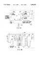
- FIGS. 3A and 3Bare block schematic diagrams of respective embodiments of the common electronic circuitry of the book of the present invention.
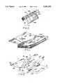
- FIG. 4is a perspective view of a continuous sheet used to form the leaves of the electronic book according to another embodiment of the invention.
- FIG. 5is a perspective view of the continuous sheet of FIG. 4 after assembly into book leaf form.
- FIG. 6is a cross-sectional view of a light emitting diode formed directly on the page of the book.
- FIG. 6Ais a cross-sectional view of a thermochromic display formed integral to the book leaf.
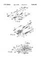
- FIG. 7Ais a perspective view of a modular substrate sheet used to form one leaf corresponding to two opposite pages of the electronic book according to another embodiment of the invention.
- FIG. 7Bis a cross-sectional view of a through page conductor employed for inter-page connections.
- FIG. 8is a perspective view of the modular substrate sheet of FIG. 7A after assembly into a modular book leaf.
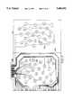
- FIG. 9is a plan view of an example of a circuit printed on the modular substrate sheet of FIG. 7A showing conductive paths through the center fold for connection, through the spine of the book, to electronic circuitry housed in the book cover.
- FIG. 10is a perspective view of a fan-like spine for receiving each modular book leaf, as shown in FIG. 8, between flaps that contain corresponding connections to the control circuitry of the book.
- FIG. 11shows a perspective view of an embodiment of the invention manufactured according to the spine and modular leaf approach illustrated in FIGS. 8 and 10.
- FIG. 12is a perspective view of another kind of substrate sheet used to form adjacent modular book spreads, each corresponding to two facing pages, of the electronic book according to yet another embodiment of the invention.
- FIG. 13is a perspective view of the modular substrate sheets of FIG. 12 after assembly into a book leaf and two corresponding book spreads.
- FIG. 14is a perspective, semi-exploded view of a fan-like spine for receiving each modular book spread while being combined to form book leaves, as shown in FIGS. 12 and 13, between flaps that contain corresponding connections to the control circuitry of the book, wherein the spine is partially extracted for illustration.
- FIG. 15is an illustration of exemplary electrical paths used to route the circuitry of the book of FIG. 12 through the last book-spread module to a terminal portion.
- FIG. 16Aillustrates an exemplary layout of the circuit of the substrate sheet shown in FIG. 12.
- FIG. 16Bis an exploded top of a momentary contact switch in accordance with one aspect of the present invention.
- FIG. 16Cis a pictorial view of the contacts of a second embodiment of the switch in accordance with the present invention.
- FIG. 17shows an exemplary layout of the circuit board layer of the single-sheet last segment, featuring the same set of connections of the circuit board layer of FIG. 16A.
- FIG. 18is a sectional view of a further embodiment of the electronic book in accordance with the present invention employing single unfolded sheet leaves.
- an electronic book 100comprises a cover 110, a multiplicity of page leaves 120, a spine 140, a head portion 150, a battery compartment 152, a speaker 154, and electronic circuitry 160.
- Cover 110suitably covers and binds page leaves 120 at an inside margin 130 to form spine 140.
- Head portion 150is suitably affixed to cover 110 and preferably incorporates electronic control circuitry 160, battery compartment 152, and speaker 154.
- pages 122suitably comprise a substrate 121 bearing visual material 126 and a circuit 123 (variously referred to a printed circuit 123, circuit layer 123 and circuit board layer 123).
- Visual material 126is suitably in the form of printed images, alphanumeric characters, or other material suitable for affixation to a book page.
- Circuit 123is suitably formed on one or both sides of substrate 121. Circuit 123 is preferably formed by printing in conductive ink, but can be formed by other conventional methods.
- Circuit 123suitably incorporates one or more electrical elements, such as, for example, switches (127, 129), active visual devices (125), heat element (resistor) and conductive terminal pads (101).
- electrical elementssuch as, for example, switches (127, 129), active visual devices (125), heat element (resistor) and conductive terminal pads (101).
- exposed conductive terminal pads 101FIG. 2B
- Pads 101are suitably accessible through an aperture, or formed (e.g., using conventional through hole techniques) on the print side of the leaf.
- Pads 101are employed to provide an electrical connecter to an extrinsic item, such as a figurine, including, e.g., a speaker and/or active visual device.
- the heat elementcan be used in conjunction with material that changes color (thermochromic) or releases scent (thermo-olfactory) when heated.
- top sheet 124may include one or more transparent or translucent portions or apertures 128 disposed at predetermined positions on sheet 124.
- Active visual devices 125such as, for example, light emitting diodes (LEDs), or electrochromic or thermochromic devices
- circuit 123may be incorporated into circuit 123, disposed in registry with non-opaque (i.e., transparent, semi-transparent, or translucent) portions or apertures 128 in top sheet 124 for visual accessibility when the page 122 is assembled in its laminated form.
- non-opaquei.e., transparent, semi-transparent, or translucent
- top sheet 124may comprise a non-opaque material, with visual material 126 printed by conventional reverse lay down processes on its underside (i.e., the side adjacent substrate 121) unprinted (bare) portions are provided to overlie the various visual display devices 125 in circuit 123.
- circuit 123is suitably formed on the side of substrate 121 adjacent top sheet 124.
- the layout of the circuit 123 corresponding to the pagedetermines the exact physical location on the page of the visual signals produced by the LEDs and visible through the non-opaque portions or apertures 128 in the top sheet 124 of that page. Of course, these locations may be the same or vary from page to page according to the specific requirements for the material being displayed. While not shown in FIG. 2A, the page on the back side of the laminated embodiment of leaf 120, is suitably of similar two-sheet laminated configuration.
- page 122can also be formed of a single (unitary) sheet bearing both the visual information (e.g., printed material) and with circuit 123, circuit 123 would be formed, suitably by printing in conductive ink, on the opposite side of the sheet or on the same side of the sheet with the printed material.
- leaves 120can be formed by printing visual materials on one side of substrate sheet 121 and forming (e.g., printing) conductive circuit 123 on the other, or by first forming (e.g., printing) circuit 123 on the substrate then overprinting with visual material 126.
- circuit 123can be printed on one side of substrate 121 (or top sheet 124), and over-printed with the visual material 126.
- the substrateis non-opaque (e.g., transparent, semi-transparent, or translucent) material (e.g., a plastic, such as polyester Melinex, Mylar, or other synthetic materials specifically treated to facilitate multi-color printing processes)
- the visual materialcan be printed by conventional reverse lay down processes on the back of substrate 121, so that the visual material is viewed through substrate 121.
- Circuit 23is then printed over the reverse laid down printing.
- an intermediate layer of "white-wash”can be printed over the reverse laid down printed material, and circuit 123 printed over the "white-wash".
- the reverse laid down printed matterand white-wash, if used) define bare areas on substrate 121, corresponding to the desired dispositions of visual devices 125.
- substrate 121would be folded to place the printed matter and circuit 123 on the interior of the fold, with the other side (e.g., non-printed side) of substrate 121 facing outward on both sides.
- Such a structureis particularly desirable in books intended for young children; the respective inks and electrical devices are secure by virtue of their location on the interior of the folded structure.
- Pages 122each suitably include one or more switches (127, 129) associated with the page, or respective portions of or images on the page.
- each pagemay include, if desired, a suitable switch mechanism 127 that is actuated when the book is opened to the corresponding page.
- Switch 127may comprise photosensitive switch elements or phototransistors, pressure sensitive switches or electromechanical contact switch elements extending outwardly from the surface of the page, or the like.
- switches 127may be formed of contact elements on the opposite pages a spread of adjacent pages (FIG. 1), so that an open circuit is created by separating the pages and separating adjacent components that otherwise form a normally closed switch assembly.
- the contacts of switch 127are suitably formed using conventional through hole technology, where circuit 123 is disposed on the rear of the substrate.
- each page 122suitably includes one or more switches 129 (e.g., 129A-129D) associated with the page, or respective portions of the page in particular, images or characters on the page.
- Switches 129are preferably momentary contact switches formed underlying printed indicia disposed at predetermined positions on the page, preferably in the vicinity of particular images, characters, words, or passages.
- switches 129may be formed, in accordance with one aspect of the present invention, employing conventional printing processes, using respective patterns of conductive, and nonconductive (e.g., dielectric) ink.
- the respective pagesare assembled such that the circuit 123 of each page is electrically connected to electronic circuit 160.
- Switch 129 (and/or 127) on the pageelectronically generates and transmits an identifying signal (such as an open or a closed circuit signal) through that page's conductive circuit 123 to the electronic circuitry 160.
- Electronic circuitry 160may be any circuit which, in response to actuation of switches 129 (and/or 127), generates a predetermined audio response and/or control signals to visual elements (e.g., LED 125) on pages 122 in accordance with the particular switch activated (and hence the corresponding visual material 126).
- Electronic circuitry 160services all of the various pages of the book and, hence, is sometimes referred to herein as "common electronic circuitry" 160.
- circuit 160may comprise one or more conventional data selector chips, such as a Hewlett Packard 74HP138 one of eight data selector IC, and a conventional integrated speech processor chip, such as a Texas Instrument TI TSP50C14 speech processor.
- the speech processoris programmed to generate signals corresponding to the desired speech or sounds, employing conventional techniques, for application to a conventional audio output device (e.g., speakers, headphones or the like).
- electronic circuit 160may include a suitable data selector (interface) circuit (or circuits) 164A (e.g., conventional data selector chips), a conventional microprocessor 166, a conventional sound generator 168 (e.g., speech synthesis chip, digital recorder, or the like, with internal or external memory or storage media), and a suitable output interface circuit 164B (e.g., multiplexer, or decoder).
- a suitable data selector (interface) circuit (or circuits) 164Ae.g., conventional data selector chips
- a conventional microprocessor 166e.g., a conventional microprocessor 166
- a conventional sound generator 168e.g., speech synthesis chip, digital recorder, or the like, with internal or external memory or storage media
- a suitable output interface circuit 164Be.g., multiplexer, or decoder
- Interface circuit 164Aconnected, as will be explained, to switches 129 (and/or 127) through circuit 123, generates in accordance with conventional techniques, a signal to microprocessor 160, indicative of the particular switches 129 (and/or 127) which are activated (e.g., rendered conductive, rendered nonconductive or otherwise change state).
- Microprocessor 166responsively generates control signals to sound generator 168 and/or output interface circuit 164B.
- Microprocessor 166is programmed, in accordance with techniques well known in the art, to generate a sequence of one or more control signals to sound generator 168 and/or output interface circuit 164B in response to actuation of particular individual switches 129 (and/or 127).
- the sequence of control signalscan be predetermined, or randomly chosen.
- a particular (generally unique) sequence of control signalsis associated with each individual switch 129 (and/or 127), or the sequence is chosen from a specific group of predetermined sequences corresponding to the switch, either randomly or in accordance with a predetermined criteria (e.g., a count of the number of times the switch is actuated, or as a function of prior actuated switches).
- Sound generator 168provides signals to a conventional audio output device 170 (e.g., speaker, headphones) to generate predetermined sounds or speech in accordance with the control signals provided by microprocessor 166.
- Interface circuit 164Bsuitably effects control (e.g., actuates, deactuates or causes a change of state) of one or more designated visual devices 125 in accordance with the control signals provided by microprocessor 166; e.g., completes a circuit between power source 162 and the designated device 125.
- electronic circuit 160effects generation of sounds and/or speech, and/or control of visual elements 125.
- circuitry 160may, alternatively, comprise a sequencer 165 and synchronizer 167 in cooperation with an integrated speech synthesizer.
- Sequencer 165 and synchronizer 167each suitably comprise 16-to-1 analog multiplexers such as sold by the Motorola Corporation of Chicago.
- An on/off switch 161selectively provides power to the respective elements of circuit 160.
- Switches 127 and/or 129are connected through the associated circuit 123 to one or both sequencer 165 and synchronizer 167, which cooperate to complete a circuit through one or more designated visual devices 125, and provide a control signal indicative of the actuated switch 127, 129 to sound generator 168.
- sequencer 165 and synchronizer 167may be implemented in a single chip, such as a Signetics CD694067 decoder/multiplexer/expansion sequencer, cooperating with a sound generator 168 Comprising a Texas Instruments TSP-50C-11 speech synthesizer and a 10 mHz synchronization crystal.
- the synthesizeris appropriately programmed employing conventional techniques.
- Page switches 127may be employed if desired to effect a sequence of visual and/or audio responses associated with the material presented on a set of pages (e.g., a spread of two adjacent pages as illustrated in FIG. 1). Switch 127 may effect the sequence automatically when book 100 is open to that set of pages (e.g., spread) or may be manually actuated.
- circuitry 160In operation, in an exemplary embodiment employing page switches 127 associated with a spread of pages, as illustrated in FIG. 1, book 100 is opened to the adjacent pages of a spread, the switch 127 associated with those pages, upon actuation, generates a signal to electronic circuitry 160. Circuit 160 then begins a sequence of visual and/or audible signals associated with the material presented on the spread. For example, the activation of switch 127 on such adjacent pages first triggers the operation of the circuitry on the left page.
- Electronic circuit 160generates signals to cause the identification and highlighting of selected portions of the printed matter 126 on that page by activating or changing the state of corresponding visual devices 125 situated next to that matter and/or through the delivery of voice messages pertaining to the printed matter, all preferably in accordance with a predetermined order and interval of presentation programmed in the electronic circuitry 160.
- Common electronic circuit 160can be programmed according to methods well known in the art of integrated circuitry, to perform any sequence of visual and/or audio signal combinations in a manner tailored to produce maximum enhancement of the material presented. If desired, when the logic of possibilities on the left page is exhausted, as determined by the specific program designed for the book, sequencer 164 automatically starts a similar series of audible and/or visual signals for the adjacent right page in conjunction with the presentation of its printed material. The sequence of signals for each page may be the same or different, depending on the preprogrammed instructions. At the conclusion of the sequence for the right page, the apparatus stops (unless forced to repeat by the reader in response to an available option, as described above for the left page) until a new pair of switch elements 127 is activated by the opening of the book at another page.
- Switches 129which may be used in conjunction with or in lieu of switch 127, preferably comprise a pressure activated momentary contact switch incorporated in the circuitry of each page and manually operated by the viewer to activate the audio and/or visual functions associated with the corresponding portion of that page (or spread of pages).
- Actuation of an individual switch 129effects a sequence or sequences associated with that switch.
- each switch 129is preferably associated with particular visual indicia, or passage, on a page or spread of pages. Alternatively, it can be associated with an entire page, or all or part of a pair of opposing pages (spread).
- the programmed presentation effected through electronic circuity 160may include interactive alternative or repetitive sequences for the viewer's choice, implemented by actuation of switches 129. For instance, at a certain point in the sequence of signal delivery effected in response to actuation of switch 29, an audible message would inform the reader of alternative progression choices in response to specific instructions communicated by the reader through the pressure switch 129 (which, in turn, could correspond to a recognizable feature in the displayed printed material). For example, after a series of light and/or sound signals associated with the printed image of a bear on the page (FIG.
- the method and apparatus of the present inventionare particularly suitable for multi-leaf compilation.
- the approach used hereutilizes novel methods for connecting the circuit 123 of each page to common electronic circuitry 160, which results in a more compact design and added versatility.
- a novel approachis also utilized in placing active visual devices 125 (e.g., LEDs) in the circuit 123 of each page in a way that reduces manufacturing costs and minimizes the space between pages occupied by the visual device, and by forming switches 129 (and 127, if utilized), and in some instances visual devices 125 employing conventional printing techniques.
- active visual devices 125e.g., LEDs
- a continuous circuit 186(corresponding to the combined circuits 123 for each page of book 100) for the entire book is printed in flexible conductive ink on one side (the top side as shown in FIG. 4) of a continuous sheet 180.
- sheet 180can be a core sheet (e.g., sheet 121) of a laminated page, or can itself bear visual information (printed matter) on the opposite side from, or on the same side as, (overlying or underlying) circuit 180.
- sheet 180is then folded into equal segments in accordion fashion to form respective book leaves consisting of pairs of adjacent segments with inside (184) and outside (182) folds. Inside folds 184 are bound together to form the book's spine 140, while the outside folds 182 constitute the outer edges of the book's pages.
- FIG. 5illustrates assembly of continuous sheet 180 into book-leaf form.
- a terminal circuit portion 188is included in printed circuit 186, on the last segment (leaf) L1 of sheet 180, to provide a convenient point of connection with electronic circuitry 160, directly with electronic devices in the circuitry or through conventional interconnecting devices (not shown in the figures). Similar terminal circuit portions 188 are also shown in FIGS. 10, 15 and 17. As shown in FIGS. 4, 5, 10, 15, and 17, terminal circuit portion 188 extends beyond the bounds of the pages to provide the convenient point of connection with electronic circuitry 160.
- Connections between circuit 186 and electronic circuitry 160can be effected, for example through a conventional mechanical connection (e.g., spring clip or spring loaded tongue connector), or through a conventional ribbon cable, connector pad or board, electrically between circuit 186 and circuitry 160.
- the terminals of circuitry 160can be disposed to conform to the disposition of terminals in portion 188, and directly connected, employing, for example, z-axis anisotropic conductive adhesive (as will hereinafter be more fully described).
- the connections between the various elements of electronic circuitry 160can be effected through circuit 186 itself; circuit 186 on end leaf L1 can include the connecting conductive paths, and the respective electronic components of common circuit 160 surface mounted on leaf L1.
- Visual devices 125, switches 127 and pressure switches 129are incorporated into continuous circuit 186 in the same manner as described in conjunction with FIG. 2; that is, the circuitry of each page is independently connected to the electronic circuitry 160 by separate conductive paths that run all the way from the particular page to last segment (leaf) L1 through the entire portion of the sheet 180 in between. The last segment L1 is then connected to electronic circuitry 160 via the terminal portion 188.
- the pagesare formed by lamination of continuous sheet 180 with matching printed material with non-opaque portions or apertures 128 corresponding to each in the circuit board layer of the book.
- the circuit 186is covered throughout the book by sheets 124 containing printed material and non-opaque portions or apertures 128 for each underlying visual device.
- a unitary page constructioni.e., visual material 126 is disposed on the substrate
- printing of the visual material (printed matter) and circuit 186can be effected concurrently, or sequentially, on the continuous sheet, prior to folding using conventional printing equipment (e.g., a Gravere printing press). Any printing equipment that is capable of effecting selective solid coverage ink transfer distribution can be utilized. It should be appreciated that by printing material corresponding to a plurality of pages of the book on the same continuous substrate (web, or large sheet) registry between the pages of printed material and printed circuits, and between the positions of the respective printed circuits, is facilitated.
- Suitable printing equipmentinclude Gravere and Flex-O-Press printing presses and screen printing apparatus. Standard multi-station offset printing presses can also be utilized, if properly configured to print circuit 186 in "solid coverage," i.e., so that ink deposited by the press printing units does not include any interstices. In other words the dots of ink deposited by the press overlap or overlay to provide a continuous conductive path.
- web-fed offset printing pressestypically include a number of successive print stations (units). Each print station is associated with a particular color, and, typically, includes upper and lower sets of rollers to selectively apply ink of that color to both sides of the web (paper; substrate 180) on a substantially concurrent basis. The web passes through the respective printing units in sequence to develop a multi-color image.
- each printing unitapplies its respective ink in accordance with an associated dot matrix (corresponding to a color separation) established by a plate.
- the operation of the individual unitsis coordinated, so that the respective matrices as printed are in registry.
- the combinations of colors and relative dispositions of the matricesprovide a composite image having the desired form, composition, and color.
- Visual matter 126 and circuit 186can be concurrently printed employing one (e.g., the upper set) of print rollers in the respective units to lay down visual matter 126, and the other (e.g., the lower set) of print rollers in the units to print circuit 186 (123).
- Disposition of a continuous conductive pathcan be facilitated by printing circuit 186 (123) employing a plurality of successive print units, each applying the conductive ink in sequence.
- the respective dot matrices laid down by the successive unitswould be slightly offset but overlay each other.
- circuit 186can be desirable to provide insulation between portions of the circuitry brought into adjacency by the folding. As will hereafter be explained, this can be done by the insertion of insulative sheets, or by overprinting the conductive ink with nonconductive or dielectric ink.
- circuit 186can be selectively, or completely coated with a layer of flexible dielectric paint, such as the product marketed by Olin Hunt Specialty Products Inc., a subsidiary of the Olin Corporation of Ontario, Calif., under the name "37AC22 Curable Spacer" or equivalent insulating material. As will be explained, this process can be employed to make switches 129 in a particularly economical fashion.
- Sheet 180is preferably made of nonconductive material capable of accepting flexible conductive ink, as taught in the prior art. Any material suitable for making book leaves, such as paper or thin plastic, which can be folded without breakage, is acceptable. Typically, the fold lines are provided through what is referred to in the art of book-making as "living-hinge” technology, which involves the formation of a hinge line by scoring it or compressing it onto the material constituting the leaf of the book. The material used may vary from pure paper to pure synthetic substances, including a variety of composite materials.
- the products sold by Paper Sources International under the trademark “Chromolux” and by the Champion International Corporation under the trademark “Cromekote”consist of paper coated on both sides with a layer of synthetic material, available in overall thicknesses from approximately 6 to 18 thousands of an inch.
- the product marketed by the Kimberly-Clark Corporation under the trademark “Kimdura”consists entirely of synthetic paper, a polypropylene material, available in thicknesses ranging from about 3 to 12 thousands of an inch.
- the materials marketed by the Spring Hill Paper Company under the trademark “Claycoat” and by the ICI Company of England under the trademark “Melinex”consist of a polyester substrate. These materials are all suitable to practice the invention and can all be folded for long-term durability by means of living hinges.
- circuit 186is printed on the back side of sheet 180
- perforations or non-opaque portionsmay be provided in sheet 180 corresponding to each visual device (e.g., LED), so that it becomes visible with printed information.
- Visual devices 125may comprise commercially available LEDs. Such LEDs are available in a variety of thicknesses approximately in the 20 to 50 thousands of an inch range. For example, Instruments Design Engineering Associates, Inc. of Brea, Calif., sells an LED approximately 50 thousands of an inch (1.3 mm) thick, which is suitable to practice this invention. A much thinner, and therefore preferable, LED is sold by citizens Electronic Company of Japan as Part No. CL-190YG-X, believed to be approximately 20 thousands of an inch thick.
- Another novel aspect of this inventionis a method of manufacture of an LED structure within the circuit 186; each LED component is formed directly in sheet 180 of the book. Instead of mounting commercially available LEDs into the network of the circuit, construction of each LED structure 125 directly into circuit 186 on each page results in significantly lower manufacturing cost and lower overall thickness of the page. Thus, as illustrated in the greatly enlarged cross-sectional view in FIG.
- an LEDcan be operationally inserted into circuit 186 at predetermined sites using techniques similar to well known methods employed for mass production of LEDs: the desired sites for the LEDs are incorporated in circuit 186 (a break of predetermined length is provided in the conductive path) during the printing process, the ends of the conductor at the break saving is terminal for the LED; a base is prepared for each LED by laying a small length of conductive tape 191 across each set of LED terminals in circuit 186; and a semiconductor die chip 192 is deposited directly into the sites.
- Tape 191is adhesive on both sides and laminated on the top side with a copper foil 193, appropriately scored in the middle to form two electrically separate copper strips.
- This kind of conductive adhesive tapeis available commercially in a variety of forms produced by the 3M Company of Saint Paul, Minn., such as copper-foil-backed 9703 Transfer Conductive Adhesive.
- the section of tape used on each LED siteis oriented so that each copper strip covers one of the terminals in the circuit 186.
- the conductivity of tape 191is uni-directional only, so that a current can flow across but not along the plane of the tape; therefore, the two copper strips 193 are initially electrically insulated from one another, but are connected through the tape 191 to the corresponding circuit terminals on which they lie, thus forming suitable electrodes for integrating semiconductor die chip 192 into circuit 186.
- Semiconductor die chip 192is then placed on the cathode side and electrically connected and bonded to the anode side by a strand of conductive epoxy resin 195 deposited on the anode side and stretched to make contact with the die chip.
- this bonding operationis performed simultaneously on multiple die chips on the tape, which is then cut to yield individual LED components.
- Each componentis then affixed with the appropriate electrical orientation to the terminals in the LED sites of the circuit board layer and covered with a sufficient amount of nonconductive epoxy resin 196 bond it to sheet 180 and to the conductive ink of the circuit board layer 186.
- the resin 196 covering the sitetends to acquire a curvature that forms a lens over the light emitting diode, thus further enhancing its effect in providing visual signals to the reader of the book.
- a corresponding perforation 194 on the adjacent segment of sheet 180is required to make the LED visible from the front side of such adjacent segment.
- the circuitry and the LEDs corresponding to each pagemay be placed on the back of the segment of core sheet corresponding to the opposite page (i.e., the back of the adjacent segment). This way, the LED can be seen through a perforation 194 placed on the page to which the LED pertains (i.e., the page on the adjacent segment).
- the LED manufacturing industryprovides standard equipment that can be used to manufacture the LEDs of the invention directly on the circuit board layer, as described above.
- Kulicke and Soffa Industries, Inc. of Willow Grove, Pa.provide several die bonders, such as the Models 6490 and 6491 Semiautomatic Die Bonders, that have proven suitable for the task.
- the average combined thickness of the conductive tape 191 and copper foil 193 used in the preferred embodiment of the inventionis approximately 1.4 thousands of an inch; the semiconductor LED die chip 192, a product marketed by Hewlett-Packard, National Semiconductor, and other companies, is less than five thousands of an inch thick, depending on the specific product used; and the conductive strand 195, formed using LED wire bond material as available from Kulicke and Soffa Industries, is also approximately 5-10 thousands of an inch thick, depending on how it is laid.
- the nonconductive protective resin 196also available form Kulicke and Soffa Industries) that is used to cover the assembly of the other parts varies in thickness as needed.
- the overall thickness of an LED so constructedis approximately 10-20 thousands of an inch, even including the arbitrary thickness of the protective lens 196. This constitutes a thickness reduction with respect to most standard LEDs, which can reduce the overall thickness of each page and permit the construction of an electronic book containing a large number of pages.
- Visual devices 125may also comprise persistent electrochromic material, displays such as described in U.S. Pat. No. 4,703,573 issued to Montgomery, et al., on Nov. 3, 1987, or thermochromic material.
- thermochromic printmay be used to implement one or more of active visual devices 125. Thermochromic printing is a well known technique. Referring to FIG. 6A, a layer of thermochromic paint or ink 600 and an adjacent (e.g., underlying) heat element, e.g., resistor 602, suitably formed of a printable layer of resistive material, such as printable carbon, between two conductive leads 186A, 186B on a support foundation (sheet 180).
- an adjacent heat elemente.g., resistor 602
- thermochromic paintWhen electric current is passed through resistor 602, the heat generated by the current causes the thermochromic paint to change color, normally from an unobtrusive grey to a bright color of choice. Thus, this technique is particularly suitable for use as an active visual element in book 100.
- a protective coating 604 of clear plasticmay be deposited (printed) over thermochromic ink 600.
- thermochromic paint and conductive materialcan be laid across sets of terminals in the circuit 186 to form a thermochromic element.
- the thermochromic elementis suitably disposed in registration with a non-opaque portion or aperture 194 in the overlying section sheet 180.
- the thermochromic element(conductor, resistor, and the thermochromic ink) can be printed on the exposed surface of sheet 180, with the conductive circuit 186 being overprinted with the visual (printed) material.
- the conductors of circuit 186can be printed on the back side of the sheet, coupled to resister 602 using conventional through hole techniques (i.e., the conductive ink is bled through the paper through sheet 180 through perforations preformed at the desired position of the thermochromic element).
- printable thermochromic paintis available in various colors from the Murfin Division of the Menasha Corporation of Neeha, Wis.; and printable carbon is available from Olin Hunt under the name "Advanced Thermoset Polymer Thick Film IL-I Graphite Conductor.”
- Thermochromic inksare normally offered in two formats. In one format the ink changes color when heated above a certain temperature and returns to its original color when cooled down. In the other format the ink is transformed into an almost transparent state by heat and returns to the original color when cooled down. The cycle can be repeated each time as the temperature is increased or decreased and is the same for both color-to-color and color-to-colorless options.
- thermochromic inks(12 offered by Menasha) with threshold temperatures ranging from -3° C. to 580 C.
- original and changed colorscan be specified within a wide range of colors, including colorless among the latter, which can be used to expose a printed design underneath the original color.
- thermochromic inkscan be printed on most ordinary printable surfaces.
- Visual devices 125can also be implemented using electro-illuminating ink, which can be laid between terminals in the circuit board layer of the invention in the same way as LEDs and thermochromic print.
- This inkis conductive, like the ink used to form the circuit 186 but it becomes luminous when current flows through it. Therefore, it affords an easy tool for illuminating the printed matter in the book with a variety of glowing colors.
- Electro-illuminating inkis available in different colors, for example, from the Murfin Division of the Menasha Corporation.
- Heat element 602can also be employed in cooperation with materials that release a scent when heated (thermo-olfactory materials).
- the conductor and resistor 602are printed on the exposed surface of sheet 180, with resistor 602 being overprinted with the scent releasing material, and conductive circuit 186 being overprinted with visual (printed) material.
- printed circuit 123 of each pageis further simplified by a modular approach to the construction of each book leaf.
- This approachassumes different configurations depending on whether a circuit 112 (corresponding to circuits 123 and 186) is printed on the front or the back side of the substrate forming the leaf.
- FIGS. 7A, 7B, 8 and 9when circuit 112 is printed on the front side, as shown in FIG. 7A, each leaf of the book consists of one substrate sheet 116 bearing printed matter (either by way of laminated printed sheet, or by directly printing on sheet 116), corresponding to two opposite pages on the same leaf, (referred to in the figure as O and E for odd and even with reference to conventional page numbering) folded at a centerline 114.
- Each sheet 116bears a circuit 112 corresponding to the specific display requirements of the two pages O and E, with the same general characteristics described above for the continuous sheet 180 of FIG. 4.
- the conductive paths of circuit 112originate/terminate in connections 113 lying across (spanning) center fold 114 of sheet 116.
- Centerfold 114becomes a common edge between the two opposite pages after folding of the core sheet and becomes part of the spine of the book after assembly into book format.
- the circuitry of each individual pagecontaining electrical elements, e.g., visual devices 125, switches 129 and, if utilized, switch 127 for that page) is self-contained, independent of the circuitry in any other page, and connected to the electronic circuitry 160 through connections 113.
- the circuit 112 of each pageis connected in parallel to the circuitry of each other page, and is controlled directly by circuitry 160 through separate connecting terminals.
- a book leaf 116is formed wherein the edge corresponding to the center fold 114 constitutes the inside margin of each opposite page O and E (and the common edge of the folded module), and wherein each page contains the half of the circuit board layer 112 that pertains to its printed material.
- connections 113which span the fold 114 of leaf 116, these connections can be used as the conductive paths to electronic circuitry 160.
- FIG. 9An example of one such circuit board layer 112 is shown in FIG. 9, wherein each active visual element site is shown with two LEDs.
- terminal connectionswould be provided along the edges opposite fold 114.
- a perforation 113Cwould be formed in sheet 116 at the desired position of terminal 113.
- conductive inkis deposited over perforation 113.
- the conductive inkwill bleed through perforation 113C so that conductive terminals (113A, 113B) are established on both sides of sheet 116, to facilitate interconnection with the other leaves.
- connections between the respective individual book leaf 116, and electronic circuit 160can be facilitated through use of a specially constructed spine.
- a specially constructed spine 221is fan like, including respective flaps 222 for receiving each book leaf 116. Flaps 222 sandwich book leaves 116 and contain connections 223 configured to correspond and, in assembly to become coupled to, connections 113 of each leaf.
- a conductive path to the electronic circuitry 160is thus formed through a last segment L2 (equivalent to the last segment L1 of the continuous sheet 180 shown in FIGS. 4 and 5). Like continuous sheet 180 of FIGS.
- spine 221is constructed by forming on a single sheet, suitably by printing in flexible conductive ink, a printed circuit 286 converging at end segment L2, for coupling with the electronic circuitry 160 through terminal portion 188.
- the continuous sheet of spine 221is folded in accordion fashion (except for the segment L2) into equal narrow segments (flaps 222) to form spine 221 as shown in FIG. 10.
- a specific conductive pathgoes from each connection 223 to the last segment L2 through spine 221 and there it is routed to a common terminal portion 188.
- FIG. 11shows a perspective view of an embodiment 200 of the invention manufactured according to the spine and modular leaf approach just described.
- the modular approachmakes it possible to use the same leaf sheet (116 for example) for the entire book, identical in all respects except for one identifying connection 113, laminated or printed with different printed material for different pages, thus greatly decreasing the cost of printing individual circuits 112 for each page.
- the versatility of the accordion approach of the first embodimentis limited by the requirement that all electrical paths for the entire set of pages be cumulatively run through the continuous core sheet to the last page for connection with the terminal board 188. This means that the complexity of each individual page is necessarily reflected in progressively crowded circuitry toward the last page, where it all converges for connection with the terminal board.
- each module of the bookcomprises one substrate sheet 216 corresponding to a spread of two facing pages (E, O) on adjacent leaves.
- Sheets 216have the same general characteristics described above for the continuous sheet 180 of FIG. 4.
- a top sheet 224 bearing printed matter and light apertures 228 (or corresponding non-opaque portions)may be affixed to each page to complete a laminated assembly (as shown in FIG. 13), or printed matter can be selectively printed directly on the substrate sheets.
- This constructionis also particularly suited for printing visual material through reverse lay down processes on a non-opaque (e.g., transparent) substrate, and overprinting circuit 212 on the visual material.
- the back of each pagesuitably contains the portion of the circuit 212 that pertains to the printed material of the opposite page of leaf 215.
- the circuitry on the back of the odd page 0 on the left module in the figurecorresponds to the printed material on the front of the even page E of the right module; similarly, the circuitry (not seen in the figures) on the back of the even page E on the right module necessarily corresponds to the printed material (also not seen) on the front of the odd page 0 of the left module.
- the respective portions of circuit 212 printed on the back of each spreadare suitably connected to other portions by connections 213 along, and preferably spanning, center fold 214. Since this configuration may cause portions of the circuit on adjacent sheets 216 to be in direct contact with one another because sandwiched between segments of adjacent spreads to form book leaves, it may be desirable to protect the circuit board layers by coating them with a layer of flexible dielectric paint, such as the Olin Hunt "37AC22 Curable Spacer" product mentioned above, or equivalent insulating material.
- Each substrate sheet 216can be plugged in modular form into a matching spine 220 (seen in FIG. 14) equivalent to the spine 221 of FIG. 10, with the connections 213 of each circuit 212 disposed to overlap corresponding connections 223 (see FIG. 10).
- Spine 220is shown in FIG. 14 only partially enmeshed with several substrate modules for clarity. Each module 216, comprising one spread of facing pages, is received between sets of flaps, with the flap interposed between the pages forming a leaf.
- Spine 220provides the point of connection for each page to common electronic circuit 160 (not shown in FIGS. 12-14); each connection 223 in the spine is tied to a conductive path that is routed through the last segment L3 of the spine to the terminal portion 188 (not seen in FIG. 14), which is in turn coupled to the electronic circuitry 160.
- FIGS. 12-14is particularly advantageous in that each pair of pages E and O on facing sides of each spread can be designed independently of the rest of the book, the only constraint being the disposition points of connection through the spine.
- the modular approachmakes it possible to use the same core sheet 216 for the entire book, with a single different connection 213 in each circuit board layer for identification purposes, laminated or printed with different printed material for different pages, thus again greatly decreasing the cost of printing individual circuits.
- Such modulescan be created, if desired, by printing a standard circuit on all modules, then selectively overprinting various connectors 213 with nonconductive ink.
- a separate spine structure (220 and 221 in FIGS. 14 and 10, respectively)can be physically omitted from the book, if connections 213 (or 113; FIGS. 7A-9) in adjacent modules overlap one another, such that the abutting connections 213 (or 113) provide sufficient electrical contact, when bound together, to form the required electrical paths to the last segment of the circuit (L2 and L3 in FIGS. 10 and 14, respectively).
- Such a constructionsis facilitated by use of conductors spanning the fold of the modules (leaves or spreads depending upon the mode of construction) at which the modules are bound together, i.e., constituting the spine.
- through hole techniquesFIG. 7B are suitably employed to extend the conductor terminal to both sides of the module.
- a particularly economical mechanism for completing the connection between remote pages (leaves) and electronic circuitry 160is effected through use of free connections 213A in each module (in FIG. 16A for example, 25 connections are shown as free, i.e., not connected to circuit 212).
- Free connections 213Aserve as bridges, through abutting connections in all adjacent modules, completing a connection from a module in which it is connected to circuit 212 of that particular module to a different module containing a conductor connected to the corresponding connection 213 completing the connection to electronic circuit 160.
- all modulesmay feature the same set of connections 213, but each module uses one different connection for coupling with electronic circuitry.
- the spine assemblies 220 and 221may be functionally replaced by a single-sheet last segment L4 containing electrical paths 386 that couple each connection 213 (or 113) on the last module 216 (or 116) to terminal portion 188 and hence to circuit 160.
- every other connection 213 (or 113) in the adjacent modulesbecomes also connected to the terminal board 188 by virtue of the contact between abutting connections 213 (or 113).
- Single-sheet segment L4can also be eliminated altogether by coupling electronic circuitry 160 directly to the connections 213 (or 113) in the spine of the book.
- abutting connections 213may be improved through use of selective disposition of conductive adhesive over abutting connections 213 (isolation between adjacent connections on sheet 216 maintained) or by general application of a strip of anisotropic conductive material (adhesive) along the bound edge.
- This materialalso referred to in the industry as a z-axis conductive membrane, is characterized by its directional electric conductivity across its thickness (the z-axis) and by its otherwise insulating characteristics in any other direction. It is available in tape form, such as the Scotch Brand 9703 Conductive Adhesive Transfer Tape sold by the 3M Company of St.
- the anisotropic conductive materialis laid on the circuit board layer 212 (or 112) to cover the connections 213 (or 113), and it is sandwiched between the modules to provide electrical contact between each pair of abutting connections without causing electrical shorting with the adjacent circuitry.
- Some of these productse.g., the Scotch transfer tape
- the book of the inventioncan be bound according to conventional book binding procedures, requiring an adhesive (such as one of the glues normally used in book-binding) to form a spine holding the modular leaves or spreads together.
- an adhesivesuch as one of the glues normally used in book-binding
- a sandwich leaf construction as illustrated in FIGS. 12-15is particularly advantageous in that a single visual device (e.g., LED, thermochromic element, or electro-illuminating ink site) can be used for two opposite pages.
- a single visual devicee.g., LED, thermochromic element, or electro-illuminating ink site
- a lens formede.g., with the nonconductive epoxy resin 196 shown in FIG. 6, may be used on both sides of the visual device to protect it from damage through the perforations 227.
- thermochromic elementstwo different thermochromics can be used around (e.g., underlying and overlying, respectively) a single resistor (e.g., strand of carbon) to produce different colors on each side.
- a single resistore.g., strand of carbon
- thermochromic elementsany combination of LEDs, electro-illuminating ink, and thermochromic elements can be used throughout the circuit board layer of the invention without affecting any of the features described in this specification.
- a "sandwich" leaf constructionis also particularly advantageous in that it facilitates the formation of switches (e.g., switches 129) employing conventional printing processes.
- switchese.g., switches 129
- conductive padsmay be printed on the interior surfaces of the respective pages of the leaf, disposed for general registry when the leaf is assembled (e.g., opposing pages folded as in FIGS. 2B, 4, 5, or brought together in binding as in FIGS. 12-14), with a spacer interposed between the pages.
- the spacercan be implemented using conventional spot gluing apparatus, or by selective printing with a nonconductive or dielectric ink.
- the sensitivity of the switchesboth as to the pressure necessary to effect a connection, and as to the necessary localization of force, is controlled, as noted above, by the pattern and relative disposition of the spacer to the conductors.
- switches 127(and 129) comprise: a respective conductive pad, 127A, disposed on the interior surface of one page (e.g., 216E) of the leaf; a corresponding pad (1270) in the portion of circuit 212 of the opposite page (2160) on the same leaf 216, and an interposed spacer, suitably pressure sensitive dielectric medium 217, such as the Olin Hunt 37AC22 Curable Spacer product mentioned above.
- Conductive pads 127A (127B)are disposed to abut corresponding pads on the opposing pages (216E, 216O) of the leaf when module 216 is folded and the leaf assembled.
- Conductive pads 127A (127B)while shown in circular configuration in FIG. 16B, may be of other configurations.
- the conductive padsmay be configured as fringes, with one conductor rotated 90° with respect to the others.
- Dielectric medium 217is interposed between pages 216E and 216O, preferably printed in a predetermined pattern on one or both of the leaf interior surfaces in predetermined positions, e.g., adjacent, circumscribing or overlying, conductive pads (127A, 127B).
- the pressure necessary to actuate the switchcan be closely controlled by forming spacer 217 as a grid having lines 217A and spaces 217B, overlying pad 127A.
- the conductive surfacescan be forced into contact through dielectric grid spaces 217B by exerting a predetermined force; the insulating function of the dielectric medium is bypassed when a certain level of pressure is exerted upon it, thus connecting the two pads and activating the switch formed by them.
- the two switches formed by the switch element pairs 127a and 127bare utilized as pressure switches to activate the odd and even page, respectively, of the leaf.
- the amount of force necessary to effect contactis a function of the denseness of the grid. Actuation at approximately 7 ounces per square inch of pressure is preferred. A seven ounce per square inch pressure requirement can be obtained by overprinting conductive pads 127A with a grid of dielectric 0.0008 inch thick, with dielectric spacer lines 217A 0.020 inch wide, and line spacing 217B of 0.02 inch.
- the dielectricincludes an annulus (ring) 217C circumscribing the conductive pad. The respective pads 127A and 127o are brought into contact through spaces 217B between grid lines 217A, only in response to pressure from directly above the pads.
- Intervening pagescause a dispersal of pressure, so that a switch on one page can be disposed underlying a switch on another page with only a few leaves interposed; e.g., leaves with switches at other dispositions between the overlying switches (the number of necessary interposed leaves is a function of the thickness of the leaves).
- one of the conductive pads (127A, 127o)would be replaced by respective proximate conductors, suitably interdigitized fingers, constituting the terminals 127X, 127Y of the switch printed on the interior surface of one of the leaf pages.
- Terminals 127X, 127Yare suitably disposed in predetermined relationship with an associated portion of the visual material on the leaf.
- a spacer 217Ais interposed between the interior surfaces of the leaf pages, and a conductive connector (not shown in FIG.
- Spacer 217Amay comprise a grid or ringed grid such as shown in FIG. 16B, disposed over terminals 127X and 127Y.
- spacer 217Amay comprise dielectric ink overprinted on terminals 127X and 127Y, as shown in FIG. 16C. Spacer 217A suitably covers approximately 60% of the surface area of terminals 127X and 127Y.
- Switches 129 for interactive sequences controlled by the viewerare similarly implemented by switch elements 129A and 129B incorporated into each half of circuit 212.
- the circuit 212 of FIG. 16Aforms switches 127 and 129 sandwiched in each leaf 215 that are used to interact with the electronic control circuitry 160 to activate and control the various audio and/or visual functions programmed for each page on that leaf.
- FIG. 17shows an exemplary layout of the last segment L4 in an embodiment of FIG. 16A, featuring the same set of connections 213 for coupling with the modules 216 in the manner shown in FIG. 15.
- Multiple switches 129are also included in the circuitry.
- matching pairs of switch elements 129form manually actuated pressure switches that give the viewer game options to enhance the recognition of printed material superimposed on each switch. For example, pressing the letter B placed over one switch may initiate a repetition of the audio display used before in the book to illustrate the letter B in conjunction with the picture of a bear, and so on.
- terminal circuit portion 188extends beyond the bounds of the pages, it remains unobstructed when segment L4 is folded along center fold 314.
- a book 1800includes a plurality of sheets 1802 (shown in FIG. 18 in greatly enlarged cross section). Sheets 1802 are suitably any material capable of accepting flexible conductive ink. Perforations 1804 are formed at predetermined positions on each sheet 1802 of the book. Printed circuits 1806 (analogous to printed circuits 123 of FIGS. 2A, 2B; 186 of FIG. 4; 112 of FIGS. 7A-9; and 212 of FIGS. 12, 15 and 16), are formed integral to sheets 1802, preferably laid down, preferably using conventional printing equipment as previously described, on each side of the sheets 1802.
- Each perforation 1804is overprinted with conductive ink, either as part of an active circuit 1806, or as a free connector 1808 (as previously discussed in connection with FIGS. 15 and 16).
- the conductive inkflows through perforation 1804 (as previously discussed in connection with FIGS. 7A and 12-14) to provide for interpage connectors, for effecting electrical connections between integral circuits 1806 and common electronic circuit 160 (not shown in FIG. 18).
- Perforations 1804are preferably of a size and configuration (e.g., round) such that a meniscus is formed extending outwardly of the opposing surface of sheet 1802 to establish the interpage connector (e.g., 1808) in a single print process.
- conductive ink circuitsare printed on both sides of the substrate, to deposit conductive ink over perforation 1804 from both sides of sheet to establish interpage terminals of a predetermined size and configuration on both sides of the leaf.
- sheets 1802may include one or more switches 1812, associated with a portion of the visual material on the page (or set of pages).
- Switches 1812suitably comprise a pair of conductive paths 1806X, and 1806Y (analogous to terminals 127X and 127Y in FIG. 16C) cooperating with an overprinted dielectric spacer 1814 (analogous to spacer 217 of FIG. 16B).
- a flexible membrane 1816 having a conductive pad 1818 disposed on the undersurface thereof, a suitably printed in flexible conductive ink (analogous to pad 1270 in FIG. 16B)is disposed over spacer 1814.
- Membrane 1816is affixed to page 1802 by a suitable adhesive.
- Visual materiale.g., images, characters, and/or text
- Visual materiale.g., images, characters, and/or text
- an anisotropic conductive adhesive 1810z-axis conductive
- Book 100may then be bound in accordance with conventional techniques; as will be understood the embodiment of FIG. 18 is particularly suited for perfect binding techniques.
Landscapes
- Engineering & Computer Science (AREA)
- Business, Economics & Management (AREA)
- Educational Administration (AREA)
- Educational Technology (AREA)
- Physics & Mathematics (AREA)
- General Physics & Mathematics (AREA)
- Theoretical Computer Science (AREA)
- Multimedia (AREA)
- Push-Button Switches (AREA)
- Devices For Indicating Variable Information By Combining Individual Elements (AREA)
- Illuminated Signs And Luminous Advertising (AREA)
- Electrically Operated Instructional Devices (AREA)
- Mechanical Treatment Of Semiconductor (AREA)
- Non-Silver Salt Photosensitive Materials And Non-Silver Salt Photography (AREA)
- Apparatuses And Processes For Manufacturing Resistors (AREA)
- Printing Methods (AREA)
- Toys (AREA)
- Electroluminescent Light Sources (AREA)
Abstract
Description
Claims (36)
Priority Applications (15)
| Application Number | Priority Date | Filing Date | Title |
|---|---|---|---|
| US07/980,649US5484292A (en) | 1989-08-21 | 1992-11-24 | Apparatus for combining audio and visual indicia |
| FI952545AFI952545A7 (en) | 1992-11-24 | 1993-11-04 | Electronic book |
| AU55940/94AAU673219B2 (en) | 1992-11-24 | 1993-11-04 | Electronic book |
| RU95118875ARU2141134C1 (en) | 1992-11-24 | 1993-11-04 | Device for combination of audio and video messages |
| CA002150013ACA2150013C (en) | 1992-11-24 | 1993-11-04 | Electronic book |
| JP6513158AJPH08505954A (en) | 1992-11-24 | 1993-11-04 | E-book |
| NZ258342ANZ258342A (en) | 1992-11-24 | 1993-11-04 | Electronic book: audio and visual enhancement of print details |
| KR1019950702092AKR950704765A (en) | 1992-11-24 | 1993-11-04 | E-book (ELECTRONIC BOOK) |
| PCT/US1993/010705WO1994012963A1 (en) | 1992-11-24 | 1993-11-04 | Electronic book |
| EP94901300AEP0676076A4 (en) | 1992-11-24 | 1993-11-04 | ELECTRONIC BOOK. |
| NZ314675ANZ314675A (en) | 1992-11-24 | 1993-11-04 | Combining visual indicia with audio: folding continuous printed circuitry to form book |
| CN93120335ACN1039944C (en) | 1992-11-24 | 1993-11-24 | Electronic book |
| US08/195,755US5609488A (en) | 1989-08-21 | 1994-02-14 | Method of combining audio and visual indicia |
| NO952042ANO952042L (en) | 1992-11-24 | 1995-05-23 | Electronic book |
| US08/898,056US6021306A (en) | 1989-08-21 | 1997-07-22 | Apparatus for presenting visual material with identified sensory material |
Applications Claiming Priority (3)
| Application Number | Priority Date | Filing Date | Title |
|---|---|---|---|
| US39612989A | 1989-08-21 | 1989-08-21 | |
| US07/685,278US5167508A (en) | 1989-08-21 | 1991-04-14 | Electronic book |
| US07/980,649US5484292A (en) | 1989-08-21 | 1992-11-24 | Apparatus for combining audio and visual indicia |
Related Parent Applications (1)
| Application Number | Title | Priority Date | Filing Date |
|---|---|---|---|
| US07/685,278Continuation-In-PartUS5167508A (en) | 1989-08-21 | 1991-04-14 | Electronic book |
Related Child Applications (2)
| Application Number | Title | Priority Date | Filing Date |
|---|---|---|---|
| US08/195,755DivisionUS5609488A (en) | 1989-08-21 | 1994-02-14 | Method of combining audio and visual indicia |
| US47470795ADivision | 1989-08-21 | 1995-06-07 |
Publications (1)
| Publication Number | Publication Date |
|---|---|
| US5484292Atrue US5484292A (en) | 1996-01-16 |
Family
ID=25527734
Family Applications (3)
| Application Number | Title | Priority Date | Filing Date |
|---|---|---|---|
| US07/980,649Expired - LifetimeUS5484292A (en) | 1989-08-21 | 1992-11-24 | Apparatus for combining audio and visual indicia |
| US08/195,755Expired - Fee RelatedUS5609488A (en) | 1989-08-21 | 1994-02-14 | Method of combining audio and visual indicia |
| US08/898,056Expired - LifetimeUS6021306A (en) | 1989-08-21 | 1997-07-22 | Apparatus for presenting visual material with identified sensory material |
Family Applications After (2)
| Application Number | Title | Priority Date | Filing Date |
|---|---|---|---|
| US08/195,755Expired - Fee RelatedUS5609488A (en) | 1989-08-21 | 1994-02-14 | Method of combining audio and visual indicia |
| US08/898,056Expired - LifetimeUS6021306A (en) | 1989-08-21 | 1997-07-22 | Apparatus for presenting visual material with identified sensory material |
Country Status (12)
| Country | Link |
|---|---|
| US (3) | US5484292A (en) |
| EP (1) | EP0676076A4 (en) |
| JP (1) | JPH08505954A (en) |
| KR (1) | KR950704765A (en) |
| CN (1) | CN1039944C (en) |
| AU (1) | AU673219B2 (en) |
| CA (1) | CA2150013C (en) |
| FI (1) | FI952545A7 (en) |
| NO (1) | NO952042L (en) |
| NZ (2) | NZ314675A (en) |
| RU (1) | RU2141134C1 (en) |
| WO (1) | WO1994012963A1 (en) |
Cited By (116)
| Publication number | Priority date | Publication date | Assignee | Title |
|---|---|---|---|---|
| US5599046A (en)* | 1994-06-22 | 1997-02-04 | Scientific Games Inc. | Lottery ticket structure with circuit elements |
| WO1997017117A1 (en) | 1995-11-07 | 1997-05-15 | Futech Educational Products, Inc. | Gameboard |
| US5681170A (en)* | 1995-06-07 | 1997-10-28 | Hasbro, Inc. | Electronic learning apparatus with self-adjusting level of difficulty |
| WO1998003962A1 (en)* | 1996-07-23 | 1998-01-29 | Junkyard Dogs, Ltd. | Electroluminescent display apparatus |
| WO1998014927A1 (en)* | 1996-09-30 | 1998-04-09 | Publications International, Ltd. | Apparatus for producing audible sounds in response to visual indicia |
| FR2755840A1 (en)* | 1996-11-15 | 1998-05-22 | Caux Jean | Luminous animation device for promotion of book in window display |
| US5807176A (en)* | 1996-07-15 | 1998-09-15 | Forsse; Earl K. | Station for providing remote interactivity with a multimedia source |
| US5810604A (en)* | 1995-12-28 | 1998-09-22 | Pioneer Publishing | Electronic book and method |
| US5897324A (en)* | 1997-02-03 | 1999-04-27 | Atop Technologies, Inc. | Multimedia-book operable with removable data storage media implemented with universal interfacing book-adapting processor |
| WO1999024954A1 (en)* | 1997-11-10 | 1999-05-20 | Sims Barnes Wanda L | Literacy training device |
| US6011545A (en)* | 1997-07-23 | 2000-01-04 | Numoncis, Inc. | Multi-panel digitizer |
| US6021306A (en)* | 1989-08-21 | 2000-02-01 | Futech Interactive Products, Inc. | Apparatus for presenting visual material with identified sensory material |
| EP0991028A2 (en) | 1998-10-03 | 2000-04-05 | Panda Eng., Inc. | Electronic verification machine for documents |
| US6064855A (en)* | 1998-04-27 | 2000-05-16 | Ho; Frederick Pak Wai | Voice book system |
| US6076734A (en)* | 1997-10-07 | 2000-06-20 | Interval Research Corporation | Methods and systems for providing human/computer interfaces |
| US6104306A (en)* | 1998-02-17 | 2000-08-15 | Buztronics, Inc. | Closure-sensitive signalling device with cantilever switch |
| US6118426A (en)* | 1995-07-20 | 2000-09-12 | E Ink Corporation | Transducers and indicators having printed displays |
| US6124851A (en)* | 1995-07-20 | 2000-09-26 | E Ink Corporation | Electronic book with multiple page displays |
| US6164541A (en)* | 1997-10-10 | 2000-12-26 | Interval Research Group | Methods and systems for providing human/computer interfaces |
| US6256638B1 (en) | 1998-04-14 | 2001-07-03 | Interval Research Corporation | Printable interfaces and digital linkmarks |
| US6298441B1 (en) | 1994-03-10 | 2001-10-02 | News Datacom Ltd. | Secure document access system |
| US20010037313A1 (en)* | 2000-05-01 | 2001-11-01 | Neil Lofgren | Digital watermarking systems |
| US6330427B1 (en) | 1999-09-08 | 2001-12-11 | Joel B. Tabachnik | Talking novelty device with book |
| US20020040472A1 (en)* | 1993-12-02 | 2002-04-04 | Hendricks John S. | Electronic book selection and delivery system having encryption and security features |
| US6376828B1 (en) | 1998-10-07 | 2002-04-23 | E Ink Corporation | Illumination system for nonemissive electronic displays |
| US6396472B1 (en)* | 1996-10-28 | 2002-05-28 | Peter L. Jacklin | Device and process for displaying images and sounds |
| US6408331B1 (en) | 1995-07-27 | 2002-06-18 | Digimarc Corporation | Computer linking methods using encoded graphics |
| US6411725B1 (en) | 1995-07-27 | 2002-06-25 | Digimarc Corporation | Watermark enabled video objects |
| US6473072B1 (en) | 1998-05-12 | 2002-10-29 | E Ink Corporation | Microencapsulated electrophoretic electrostatically-addressed media for drawing device applications |
| US20030116620A1 (en)* | 1999-08-09 | 2003-06-26 | Jin Song | Method and system for illustrating sound and text |
| US6608618B2 (en)* | 2001-06-20 | 2003-08-19 | Leapfrog Enterprises, Inc. | Interactive apparatus using print media |
| US20030170604A1 (en)* | 2002-03-05 | 2003-09-11 | Mullen Jeffrey D. | Talking book employing photoelectronics for autonomous page recognition |
| US20030175672A1 (en)* | 2002-03-18 | 2003-09-18 | Kyoung-Ho Kim | Voice book device |
| US6647130B2 (en) | 1993-11-18 | 2003-11-11 | Digimarc Corporation | Printable interfaces and digital linking with embedded codes |
| US20040027327A1 (en)* | 2002-06-10 | 2004-02-12 | E Ink Corporation | Components and methods for use in electro-optic displays |
| US6697602B1 (en) | 2000-02-04 | 2004-02-24 | Mattel, Inc. | Talking book |
| US20040155857A1 (en)* | 2002-09-03 | 2004-08-12 | E Ink Corporation | Electro-optic displays |
| US20050007336A1 (en)* | 1997-08-28 | 2005-01-13 | E Ink Corporation | Adhesive backed displays |
| US20050011376A1 (en)* | 2001-08-30 | 2005-01-20 | Barry Mak | Embossing tools and tape printers |
| US20050012758A1 (en)* | 2003-06-25 | 2005-01-20 | Christou Charlotte L. | Digital picture frame |
| US20050026128A1 (en)* | 2003-02-18 | 2005-02-03 | Leapfrog Enterprises, Inc. | Print media apparatus for young children |
| US20050023338A1 (en)* | 2003-04-22 | 2005-02-03 | Larry Goldenberg | Photograph album accessory including audio playback device |
| US20050024884A1 (en)* | 2003-07-30 | 2005-02-03 | Seminara Dominick M. | Illuminated personal safety device for use by cyclists and joggers |
| US20050036640A1 (en)* | 2003-08-11 | 2005-02-17 | Larry Goldenberg | Small-size accessory with audio recording and playback device and transparent wall for holding and viewing an article |
| US20050048459A1 (en)* | 2003-08-29 | 2005-03-03 | Gubitosi Domenic T. | Educational toy with actuators and correlated audible and visual output |
| US20050076548A1 (en)* | 2003-09-05 | 2005-04-14 | Devos John A. | Printed sensor having opposed areas of nonvisible conductive ink |
| US20050082820A1 (en)* | 2002-10-09 | 2005-04-21 | Nelson Veronica A. | Flexible sheet having at least one region of electroluminescence |
| US20050122564A1 (en)* | 1999-05-03 | 2005-06-09 | E Ink Corporation | Machine-readable displays |
| US20050175973A1 (en)* | 2004-02-05 | 2005-08-11 | Miller David E. | Textbook with supplemental multimedia capability |
| US6934855B1 (en) | 1998-10-13 | 2005-08-23 | Nds Limited | Remote administration of smart cards for secure access systems |
| US20060139308A1 (en)* | 1995-07-20 | 2006-06-29 | E Ink Corporation | Addressing schemes for electronic displays |
| US20060176267A1 (en)* | 2003-07-24 | 2006-08-10 | E Ink Corporation | Improvements in electro-optic displays |
| US7106296B1 (en) | 1995-07-20 | 2006-09-12 | E Ink Corporation | Electronic book with multiple page displays |
| US20060202795A1 (en)* | 2003-03-12 | 2006-09-14 | Harald Hoeppner | Method for the production of a book cover insert and book-type security document and book cover insert and book-type security document |
| US7110164B2 (en) | 2002-06-10 | 2006-09-19 | E Ink Corporation | Electro-optic displays, and processes for the production thereof |
| US20060279527A1 (en)* | 1999-05-03 | 2006-12-14 | E Ink Corporation | Machine-readable displays |
| US7174295B1 (en)* | 1999-09-06 | 2007-02-06 | Nokia Corporation | User interface for text to speech conversion |
| US20070052757A1 (en)* | 1996-07-19 | 2007-03-08 | E Ink Corporation | Electronically addressable microencapsulated ink and display thereof |
| US7203455B2 (en) | 2002-05-30 | 2007-04-10 | Mattel, Inc. | Interactive multi-sensory reading system electronic teaching/learning device |
| US20070097100A1 (en)* | 2005-11-01 | 2007-05-03 | James Marggraff | Method and system for invoking computer functionality by interaction with dynamically generated interface regions of a writing surface |
| US20070151487A1 (en)* | 2005-10-24 | 2007-07-05 | Allan Villapanda | Portable desktop |
| US20070153361A1 (en)* | 2002-06-10 | 2007-07-05 | E Ink Corporation | Components and testing methods for use in the production of electro-optic displays |
| US20070201702A1 (en)* | 1992-12-09 | 2007-08-30 | Discovery Communications, Inc. | Electronic book security and copyright protection system |
| US20070262579A1 (en)* | 2006-05-11 | 2007-11-15 | Xerox Corporation | Substrate fluorescence pattern mask for embedding information in printed documents |
| US20070264476A1 (en)* | 2006-05-11 | 2007-11-15 | Xerox Corporation | Substrate fluorescence mask for embedding information in printed documents |
| US20080043318A1 (en)* | 2005-10-18 | 2008-02-21 | E Ink Corporation | Color electro-optic displays, and processes for the production thereof |
| US7336788B1 (en) | 1992-12-09 | 2008-02-26 | Discovery Communicatoins Inc. | Electronic book secure communication with home subsystem |
| US20080057252A1 (en)* | 2002-06-10 | 2008-03-06 | E Ink Corporation | Components and methods for use in electro-optic displays |
| US20080070216A1 (en)* | 2006-09-20 | 2008-03-20 | James Becker | Book having audio information |
| US7401286B1 (en) | 1993-12-02 | 2008-07-15 | Discovery Communications, Inc. | Electronic book electronic links |
| US7402042B2 (en) | 2002-05-30 | 2008-07-22 | Mattel, Inc. | Electronic learning device for an interactive multi-sensory reading system |
| US7436976B2 (en) | 1995-07-27 | 2008-10-14 | Digimarc Corporation | Digital watermarking systems and methods |
| US20080254428A1 (en)* | 2003-01-31 | 2008-10-16 | Mattel, Inc. | Interactive electronic device with optical page identification system |
| US20080299333A1 (en)* | 2007-05-29 | 2008-12-04 | Xerox Corporation | Substrate fluorescent non-overlapping dot patterns for embedding information in printed documents |
| US20080305444A1 (en)* | 2007-06-05 | 2008-12-11 | Xerox Corporation | Infrared encoding of security elements using standard xerographic materials with distraction patterns |
| US20080302263A1 (en)* | 2007-06-05 | 2008-12-11 | Xerox Corporation | Infrared encoding of security elements using standard xerographic materials |
| US7509270B1 (en) | 1992-12-09 | 2009-03-24 | Discovery Communications, Inc. | Electronic Book having electronic commerce features |
| US20090122349A1 (en)* | 2007-11-09 | 2009-05-14 | Xerox Corporation | Fluorescence-based correlation mark for enhanced security in printed documents |
| US20090179873A1 (en)* | 2003-02-10 | 2009-07-16 | Wood Michael C | Interactive hand held apparatus with stylus |
| US20090191531A1 (en)* | 2007-12-21 | 2009-07-30 | Joseph Saccocci | Method and Apparatus for Integrating Audio and/or Video With a Book |
| US7583251B2 (en) | 1995-07-20 | 2009-09-01 | E Ink Corporation | Dielectrophoretic displays |
| US20090241054A1 (en)* | 1993-12-02 | 2009-09-24 | Discovery Communications, Inc. | Electronic book with information manipulation features |
| US20100012396A1 (en)* | 2006-10-24 | 2010-01-21 | Yasuji Ogawa | Operating Tool with Conductor Pieces |
| US7716349B1 (en) | 1992-12-09 | 2010-05-11 | Discovery Communications, Inc. | Electronic book library/bookstore system |
| US20100165446A1 (en)* | 2002-06-10 | 2010-07-01 | E Ink Corporation | Components and methods for use in electro-optic displays |
| US7831933B2 (en) | 2004-03-17 | 2010-11-09 | Leapfrog Enterprises, Inc. | Method and system for implementing a user interface for a device employing written graphical elements |
| US7839564B2 (en) | 2002-09-03 | 2010-11-23 | E Ink Corporation | Components and methods for use in electro-optic displays |
| US7849393B1 (en) | 1992-12-09 | 2010-12-07 | Discovery Communications, Inc. | Electronic book connection to world watch live |
| US7853193B2 (en) | 2004-03-17 | 2010-12-14 | Leapfrog Enterprises, Inc. | Method and device for audibly instructing a user to interact with a function |
| US7861166B1 (en)* | 1993-12-02 | 2010-12-28 | Discovery Patent Holding, Llc | Resizing document pages to fit available hardware screens |
| US7865567B1 (en) | 1993-12-02 | 2011-01-04 | Discovery Patent Holdings, Llc | Virtual on-demand electronic book |
| US7916124B1 (en) | 2001-06-20 | 2011-03-29 | Leapfrog Enterprises, Inc. | Interactive apparatus using print media |
| US7922099B1 (en) | 2005-07-29 | 2011-04-12 | Leapfrog Enterprises, Inc. | System and method for associating content with an image bearing surface |
| US20110164307A1 (en)* | 2002-06-10 | 2011-07-07 | E Ink Corporation | Electro-optic displays, and processes for the production thereof |
| US20110169257A1 (en)* | 2008-07-31 | 2011-07-14 | Kate Stone | Book |
| US8073695B1 (en) | 1992-12-09 | 2011-12-06 | Adrea, LLC | Electronic book with voice emulation features |
| US8095949B1 (en) | 1993-12-02 | 2012-01-10 | Adrea, LLC | Electronic book with restricted access features |
| US8261967B1 (en) | 2006-07-19 | 2012-09-11 | Leapfrog Enterprises, Inc. | Techniques for interactively coupling electronic content with printed media |
| CN101534709B (en)* | 2007-07-05 | 2012-10-10 | “索弗莱门纳亚伊姆佩丹纳亚医疗技术”股份责任有限公司 | Electroimpedance computer mammograph |
| US8599143B1 (en) | 2006-02-06 | 2013-12-03 | Leapfrog Enterprises, Inc. | Switch configuration for detecting writing pressure in a writing device |
| US20130346838A1 (en)* | 2009-11-10 | 2013-12-26 | Dulcetta, Inc. | Dynamic audio playback of soundtracks for electronic visual works |
| US8641220B1 (en) | 2013-07-01 | 2014-02-04 | Fujian Yibao Optoelectronics Technology Co., Ltd. | Lighted footwear |
| US8860011B2 (en) | 2003-01-24 | 2014-10-14 | Semiconductor Energy Laboratory Co., Ltd. | Semiconductor device, and electronic book including double-sided light emitting display panel |
| US8960936B1 (en)* | 2012-01-19 | 2015-02-24 | Shelley A. Malcolm | Backlit storybook for the visually impaired |
| US9053640B1 (en) | 1993-12-02 | 2015-06-09 | Adrea, LLC | Interactive electronic book |
| WO2015089508A1 (en)* | 2013-12-13 | 2015-06-18 | Cirque Corporation | Secure cage created by re-distribution layer metallization |
| US20150227803A1 (en)* | 2012-08-24 | 2015-08-13 | Moleskine S.P.A. | Notebook and method for digitizing notes |
| US20150308639A1 (en)* | 2014-04-29 | 2015-10-29 | Tactotek Oy | Method for manufacturing electronic products, related arrangement and product |
| US9470950B2 (en) | 2002-06-10 | 2016-10-18 | E Ink Corporation | Electro-optic displays, and processes for the production thereof |
| US9646584B1 (en)* | 2015-12-15 | 2017-05-09 | Chris Dorety | Visual aid for improvised music |
| US9664978B2 (en) | 2002-10-16 | 2017-05-30 | E Ink Corporation | Electrophoretic displays |
| CN108492805A (en)* | 2018-04-24 | 2018-09-04 | 凯涛电子(上海)有限公司 | Multi-mode portable electronics audio device and system |
| US10643484B2 (en)* | 2014-10-16 | 2020-05-05 | Hallmark Cards, Incorporated | Capacitive gesture recognition book |
| US11250794B2 (en) | 2004-07-27 | 2022-02-15 | E Ink Corporation | Methods for driving electrophoretic displays using dielectrophoretic forces |
| US11754271B2 (en) | 2013-07-01 | 2023-09-12 | Fujian Yibao Optoelectronics Technology Co., Ltd. | Lighted footwear |
| US20240304117A1 (en)* | 2023-03-07 | 2024-09-12 | Designled Technology Corp. | Easily Curved LED Display Module |
Families Citing this family (92)
| Publication number | Priority date | Publication date | Assignee | Title |
|---|---|---|---|---|
| JP3895830B2 (en) | 1997-06-18 | 2007-03-22 | インテリジェントディスク株式会社 | Storage medium having electronic circuit |
| JPH117296A (en)* | 1997-06-18 | 1999-01-12 | Oputoromu:Kk | Storage medium having electronic circuit and speech synthesizer having the storage medium |
| US20010044864A1 (en)* | 1997-06-18 | 2001-11-22 | Kabushiki Kaisha Optrom | Disk storage system having an electronic circuit mounted on the surface of the disk and control method thereof |
| TW389894B (en) | 1997-06-19 | 2000-05-11 | Optrom Kk | Device for exchanging information with storage medium having electronic circuit and the electronic circuit, and system including the same |
| KR100208019B1 (en)* | 1997-07-16 | 1999-07-15 | 윤종용 | Multi-purpose training system |
| IT1299128B1 (en)* | 1997-12-17 | 2000-02-07 | Ilario Bertotti | SMART ROAD MAP |
| US6419158B2 (en) | 1998-03-27 | 2002-07-16 | Peter Hooglander | System and method for carrying medical and/or personal information |
| US6882824B2 (en)* | 1998-06-10 | 2005-04-19 | Leapfrog Enterprises, Inc. | Interactive teaching toy |
| US5944533A (en)* | 1998-06-10 | 1999-08-31 | Knowledge Kids Enterprises, Inc. | Interactive educational toy |
| US6377780B2 (en) | 1999-06-09 | 2002-04-23 | Shelcore Inc. | Device for displaying multiple scenes animated by sequences of light |
| US6405167B1 (en)* | 1999-07-16 | 2002-06-11 | Mary Ann Cogliano | Interactive book |
| US7110945B2 (en)* | 1999-07-16 | 2006-09-19 | Dreamations Llc | Interactive book |
| KR100530911B1 (en)* | 1999-10-01 | 2005-11-23 | 세이코 엡슨 가부시키가이샤 | Wiring board, semiconductor device and method of producing, testing and packaging the same, and circuit board and electronic equipment |
| US9640083B1 (en) | 2002-02-26 | 2017-05-02 | Leapfrog Enterprises, Inc. | Method and system for providing content for learning appliances over an electronic communication medium |
| US9520069B2 (en)* | 1999-11-30 | 2016-12-13 | Leapfrog Enterprises, Inc. | Method and system for providing content for learning appliances over an electronic communication medium |
| US6668156B2 (en)* | 2000-04-27 | 2003-12-23 | Leapfrog Enterprises, Inc. | Print media receiving unit including platform and print media |
| US6933928B1 (en)* | 2000-07-18 | 2005-08-23 | Scott E. Lilienthal | Electronic book player with audio synchronization |
| US6549751B1 (en) | 2000-07-25 | 2003-04-15 | Giuseppe Li Mandri | Multimedia educational system |
| US6824066B2 (en)* | 2000-10-06 | 2004-11-30 | Leon H. Weyant | Electronic access security key card pamphlet |
| RU2197748C2 (en)* | 2000-10-31 | 2003-01-27 | Российский государственный гуманитарный университет | Method and device for training and digesting training appliances |
| RU2180455C1 (en)* | 2000-10-31 | 2002-03-10 | Российский государственный гуманитарный университет | Method for purposeful control of learning educational materials |
| RU2170132C1 (en)* | 2000-12-15 | 2001-07-10 | Смирнов Александр Витальевич | Sound reproducing device (modifications) |
| US20020097159A1 (en)* | 2001-01-19 | 2002-07-25 | Peter Hooglander | System and method using medical information-containing electronic devices |
| US20030129572A1 (en)* | 2002-01-05 | 2003-07-10 | Leapfrog Enterprises, Inc. | Learning center |
| US7252510B1 (en)* | 2002-04-30 | 2007-08-07 | Mattel, Inc. | Entertainment device and method of using the same |
| US6966777B2 (en)* | 2002-08-01 | 2005-11-22 | Teresa Robotham | Tool device, system and method for teaching reading |
| GB0227040D0 (en)* | 2002-11-20 | 2002-12-24 | Sexton Conrad | Greetings card |
| US20050260551A1 (en)* | 2003-03-27 | 2005-11-24 | Rubin Aaron C | Reading book including partially electronic page display |
| US7242315B2 (en)* | 2003-05-13 | 2007-07-10 | Atg Design Works, Llc | Self contained device for displaying electronic information |
| US20050076438A1 (en)* | 2003-10-08 | 2005-04-14 | Leapfrog Enterprises, Inc. | Foldable structure capable of being configured as a book |
| US7152856B2 (en)* | 2003-11-17 | 2006-12-26 | Canon Kabushiki Kaisha | Sheet processing apparatus and image processing apparatus |
| US7612677B2 (en) | 2005-01-28 | 2009-11-03 | Smartrac Ip B.V. | Method for producing a security layered construction and security layered construction and identification documents containing such a construction |
| US20050191604A1 (en)* | 2004-02-27 | 2005-09-01 | Allen William H. | Apparatus and method for teaching dyslexic individuals |
| US20060077184A1 (en)* | 2004-03-17 | 2006-04-13 | James Marggraff | Methods and devices for retrieving and using information stored as a pattern on a surface |
| US20060078866A1 (en)* | 2004-03-17 | 2006-04-13 | James Marggraff | System and method for identifying termination of data entry |
| US20060073444A1 (en)* | 2004-09-23 | 2006-04-06 | Rines Robert H | Method of and apparatus for supplementing the reading of selected passages of printed material in a book or the like by voice or acoustic pronouncement of coded indicia provided in the book at such passages, remotely to access the playing of corresponding coded tracks of pre-recorded video/audio supplemental material respectively related to the selected passages |
| GB2428505B (en)* | 2004-03-24 | 2009-01-07 | Robert Harvey Rines | Electronic & accoustic reading of printed material |
| US20050214730A1 (en)* | 2004-03-24 | 2005-09-29 | Rines Robert H | Method of and apparatus for supplementing the reading of selected passages of printed material in a book or the like by electronically reading coded indicia provided in the book at such passages to access the playing of corresponding coded tracks of pre-recorded video/audio supplemental material respectively related to the selected passages |
| US7436318B2 (en)* | 2004-04-19 | 2008-10-14 | Atg Designworks, Llc | Self contained device for displaying electronic information |
| JP2006301085A (en)* | 2005-04-18 | 2006-11-02 | Toppan Forms Co Ltd | Voice message transmission sheet and voice board |
| NL1031355C2 (en)* | 2006-03-13 | 2007-09-14 | Najim El Boumassaoudi | Aid device is for self-study and comprises at least one page, which on at least one and preferably two sides is provided with illustrations |
| US7748634B1 (en)* | 2006-03-29 | 2010-07-06 | Amazon Technologies, Inc. | Handheld electronic book reader device having dual displays |
| US9384672B1 (en) | 2006-03-29 | 2016-07-05 | Amazon Technologies, Inc. | Handheld electronic book reader device having asymmetrical shape |
| US8413904B1 (en) | 2006-03-29 | 2013-04-09 | Gregg E. Zehr | Keyboard layout for handheld electronic book reader device |
| GB0611452D0 (en) | 2006-06-12 | 2006-07-19 | Plastic Logic Ltd | Page refreshing e-reader |
| GB2440730B (en)* | 2006-06-22 | 2008-11-26 | Emmanouil Kelaidis | A method of making a book |
| GB2439591A (en)* | 2006-06-30 | 2008-01-02 | Liesbeth Oosterwijk | Sound book apparatus |
| WO2008054715A2 (en)* | 2006-10-31 | 2008-05-08 | Solicore, Inc. | Powered print advertisements, product packaging, and trading cards |
| WO2008054714A2 (en)* | 2006-10-31 | 2008-05-08 | Solicore, Inc. | Powered authenticating cards |
| JP4997399B2 (en)* | 2006-12-27 | 2012-08-08 | 株式会社ジャパンディスプレイセントラル | Liquid crystal display |
| US8181879B2 (en)* | 2006-12-29 | 2012-05-22 | Solicore, Inc. | Mailing apparatus for powered cards |
| WO2008082616A1 (en)* | 2006-12-29 | 2008-07-10 | Solicore, Inc. | Card configured to receive separate battery |
| CN101241651A (en)* | 2007-02-01 | 2008-08-13 | 邝天立 | Sounding book and method for providing relevant audio for printed picture or text by using sounding book |
| US8253654B2 (en)* | 2007-03-16 | 2012-08-28 | Motorola Mobility Llc | Visual interface control based on viewing display area configuration |
| US8149183B2 (en)* | 2007-07-31 | 2012-04-03 | Hewlett-Packard Development Company, L.P. | Display |
| GB2454032A (en) | 2007-10-24 | 2009-04-29 | Plastic Logic Ltd | Edgeless document viewer |
| US8342844B1 (en) | 2008-02-13 | 2013-01-01 | Evans Elena M | Visual aid and process for demonstrating the formation of colors |
| GB2462290B (en)* | 2008-07-31 | 2011-02-23 | Novalia Ltd | Printed article |
| KR100896910B1 (en)* | 2008-08-25 | 2009-05-12 | 주식회사 씽코웰 | Mat for children's learning using toys |
| GB2463266B (en)* | 2008-09-05 | 2011-07-27 | Plastic Logic Ltd | Electronic document reader |
| CN102387926A (en)* | 2009-04-06 | 2012-03-21 | 徐涛 | Rotatable binder set for page identification |
| US8471824B2 (en)* | 2009-09-02 | 2013-06-25 | Amazon Technologies, Inc. | Touch-screen user interface |
| US8451238B2 (en) | 2009-09-02 | 2013-05-28 | Amazon Technologies, Inc. | Touch-screen user interface |
| US9262063B2 (en)* | 2009-09-02 | 2016-02-16 | Amazon Technologies, Inc. | Touch-screen user interface |
| US8624851B2 (en)* | 2009-09-02 | 2014-01-07 | Amazon Technologies, Inc. | Touch-screen user interface |
| GB0916806D0 (en) | 2009-09-24 | 2009-11-04 | Plastic Logic Ltd | Touch screen displays |
| GB2524419B (en) | 2009-10-23 | 2015-10-28 | Flexenable Ltd | Electronic document reading devices |
| GB201000021D0 (en) | 2010-01-04 | 2010-02-17 | Plastic Logic Ltd | Electronic document reading devices |
| CN102314778A (en)* | 2010-06-29 | 2012-01-11 | 鸿富锦精密工业(深圳)有限公司 | Electronic reader |
| GB201012012D0 (en) | 2010-07-16 | 2010-09-01 | Novalia Ltd | Laminate |
| JP5609507B2 (en)* | 2010-10-04 | 2014-10-22 | ソニー株式会社 | Information processing apparatus, information processing method, and program |
| JP5671921B2 (en)* | 2010-10-04 | 2015-02-18 | ソニー株式会社 | Information processing apparatus, information processing method, and program |
| GB2487576B (en) | 2011-01-28 | 2013-07-03 | Novalia Ltd | Book |
| US10060207B2 (en) | 2011-10-05 | 2018-08-28 | Helix Energy Solutions Group, Inc. | Riser system and method of use |
| GB2501689B (en) | 2012-04-30 | 2016-10-19 | Novalia Ltd | Printed article |
| CN102785502A (en)* | 2012-08-01 | 2012-11-21 | 东莞明彩纸品有限公司 | A Voice Stability Book |
| CN102941742B (en)* | 2012-10-19 | 2015-08-12 | 刘瑛 | A kind of physical book system with interactive function |
| US8977555B2 (en) | 2012-12-20 | 2015-03-10 | Amazon Technologies, Inc. | Identification of utterance subjects |
| US20140241784A1 (en)* | 2013-02-26 | 2014-08-28 | Jeff Baker | Interactive retaining device |
| WO2015092785A1 (en)* | 2013-12-17 | 2015-06-25 | Simhi Doron | Slides projector book device |
| WO2016205555A1 (en)* | 2015-06-16 | 2016-12-22 | Video Plus Print Company | Multi-sensory presentation device |
| US10203773B2 (en)* | 2015-08-29 | 2019-02-12 | Bragi GmbH | Interactive product packaging system and method |
| JP6575601B2 (en)* | 2016-04-01 | 2019-09-18 | 凸版印刷株式会社 | Print body, print body management apparatus, information output system, page identification method of print body, book cover, cover of print body |
| CN106515254A (en)* | 2016-12-02 | 2017-03-22 | 安徽壁虎智能科技有限公司 | Difunctional book and manufacturing method thereof |
| CN106908968A (en)* | 2017-04-20 | 2017-06-30 | 武汉大学 | A kind of printed electronic paper media of integrated multicomponent device |
| CN107316510A (en)* | 2017-06-21 | 2017-11-03 | 南京福图信息科技有限公司 | A kind of trans-printing type children teaching aid based on electrically conductive ink |
| CN108022465A (en)* | 2017-12-14 | 2018-05-11 | 大连高马艺术设计工程有限公司 | An interactive picture book system for learning Chinese characters based on embedded systems and hand-painted circuits |
| US11610499B2 (en) | 2018-03-26 | 2023-03-21 | Hewlett-Packard Development Company, L.P. | Printed circuitry |
| CN108831264A (en)* | 2018-05-30 | 2018-11-16 | 李倩 | A kind of home test e-book |
| RU2721344C1 (en)* | 2019-12-05 | 2020-05-19 | Общество с ограниченной ответственностью «ВОЙС ГРУПП МЕДИА» | Interactive book and electronic substrate for interactive book |
| CN114333449B (en)* | 2021-04-03 | 2024-04-05 | 武汉世帝牧文化传媒有限公司 | Sounding book |
| CN116512793A (en)* | 2022-12-14 | 2023-08-01 | 王新诚 | Book using wireless power transmission technology |
Citations (48)
| Publication number | Priority date | Publication date | Assignee | Title |
|---|---|---|---|---|
| US1475430A (en)* | 1922-02-27 | 1923-11-27 | Curwen John Spedding | Advertising device or toy |
| US1545217A (en)* | 1924-01-10 | 1925-07-07 | Ginn And Company | Test paper |
| US1670254A (en)* | 1922-03-31 | 1928-05-15 | Gowin Enoch Burton | Educational folder |
| US2277318A (en)* | 1941-03-14 | 1942-03-24 | Joseph E Grant | Bookbinding |
| US2444355A (en)* | 1946-09-11 | 1948-06-29 | Joseph D Kniznick | Strip binder for record albums or scrapbooks |
| US2524143A (en)* | 1948-01-08 | 1950-10-03 | Willard D Smith | Educational art and apparatus |
| US2826844A (en)* | 1953-11-27 | 1958-03-18 | Leika Walter | Illuminated greeting cards |
| US2997306A (en)* | 1959-05-04 | 1961-08-22 | Hicks Walter Robert | Book with talking pages |
| US3086297A (en)* | 1961-08-21 | 1963-04-23 | Louise A Kay | Talking book |
| US3096271A (en)* | 1958-11-26 | 1963-07-02 | Burroughs Corp | Data display device |
| US3220126A (en)* | 1960-05-04 | 1965-11-30 | Sono Libra Inc | Multisensory intelligence transmission devices |
| US3522665A (en)* | 1967-12-12 | 1970-08-04 | Sprague Electric Co | Teaching system |
| US3529832A (en)* | 1968-02-08 | 1970-09-22 | Mattel Inc | Sound illustrated book |
| US3540132A (en)* | 1968-10-25 | 1970-11-17 | Marvin Glass & Associates | Audio visual educational toy |
| US3553851A (en)* | 1969-03-27 | 1971-01-12 | Richard E Paige | Talking book |
| US3592098A (en)* | 1969-05-21 | 1971-07-13 | Ernest A Zadig | Electronic musical instrument employing plural tuning sheets and a hand-held selector |
| US3648387A (en)* | 1969-11-24 | 1972-03-14 | Xerox Corp | Educational aid |
| US3738021A (en)* | 1969-10-20 | 1973-06-12 | Matsushita Electric Industrial Co Ltd | System for synchronizing sounds with learning materials |
| US3798806A (en)* | 1973-05-14 | 1974-03-26 | D Sanford | Musical greeting card |
| US3803580A (en)* | 1972-02-18 | 1974-04-09 | Litton Systems Inc | Apparatus for operation of indicators and controls shown in a pictorial illustration |
| USRE28199E (en)* | 1973-06-01 | 1974-10-15 | Electro-optical device having variable optical density | |
| US4021932A (en)* | 1975-07-31 | 1977-05-10 | Lipps Edwin A | Audiovisual device |
| US4044229A (en)* | 1972-07-21 | 1977-08-23 | Nikolay Samreus | Device for electroconductive connection and reading |
| US4055014A (en)* | 1976-03-25 | 1977-10-25 | The Maytronics Group, Inc. | Lighted greeting cards |
| US4102067A (en)* | 1976-10-06 | 1978-07-25 | Tarrant Fred A | Combined greeting card and music box structure |
| US4158264A (en)* | 1977-08-31 | 1979-06-19 | Orth Joy H | Audio-visual teaching apparatus |
| US4209824A (en)* | 1978-02-02 | 1980-06-24 | Kaufman Beverly F | Electrically illuminated book |
| US4222188A (en)* | 1978-09-22 | 1980-09-16 | Tarrant Fred A | Combined merchandise display, sound reproduction device and insignia supporting unit |
| US4236156A (en)* | 1979-04-23 | 1980-11-25 | Vought Corporation | Switching of thermochromic and pressure sensitive films with surface acoustic waves |
| US4273538A (en)* | 1978-09-06 | 1981-06-16 | Douglas Alan Ross | Educational aid |
| WO1981002215A1 (en)* | 1980-02-01 | 1981-08-06 | M Segan | Audio-visual message device |
| US4286399A (en)* | 1979-07-25 | 1981-09-01 | Matsushita Electric Industrial Co., Ltd. | Card or book involving luminescence |
| US4299041A (en)* | 1979-09-20 | 1981-11-10 | Wilson Stephen H | Animated device |
| US4363081A (en)* | 1980-07-02 | 1982-12-07 | Wilbur Robert W | Illuminated greeting cards |
| US4425098A (en)* | 1981-08-21 | 1984-01-10 | Doering Erich | Sound-illustrated, bound book |
| US4497126A (en)* | 1984-04-06 | 1985-02-05 | Rodrigue Dejean | Greeting card with illuminated message and design |
| US4531310A (en)* | 1984-01-10 | 1985-07-30 | Futures Unlimited, Inc. | Display element |
| US4636881A (en)* | 1984-09-10 | 1987-01-13 | James T. Shaw | Talking book with an infrared detector used to detect page turning |
| US4656469A (en)* | 1983-11-17 | 1987-04-07 | Oliver Earl H | Activated work and method of forming same |
| US4703573A (en)* | 1985-02-04 | 1987-11-03 | Montgomery John W | Visual and audible activated work and method of forming same |
| US4706536A (en)* | 1986-02-05 | 1987-11-17 | Jtg Of Nashville, Inc. | Membrane keyboard for songbook tone generator |
| US4733127A (en)* | 1984-06-12 | 1988-03-22 | Sanyo Electric Co., Ltd. | Unit of arrayed light emitting diodes |
| US4752230A (en)* | 1986-05-02 | 1988-06-21 | Dainippon Kaiga Co., Ltd. | Picture book |
| US4778391A (en)* | 1986-01-26 | 1988-10-18 | Weiner Avish J | Sound-producing amusement or educational devices |
| US4809246A (en)* | 1987-04-24 | 1989-02-28 | Lih Jeng | Sound illustrated book having page indicator circuit |
| FR2625011A1 (en)* | 1987-12-18 | 1989-06-23 | Info Media Communication | Device for detecting information by means of electrical circuits integrated within a sheet of paper |
| US4990092A (en)* | 1989-08-14 | 1991-02-05 | Tonka Corporation | Talking book |
| US5209665A (en)* | 1989-10-12 | 1993-05-11 | Sight & Sound Incorporated | Interactive audio visual work |
Family Cites Families (23)
| Publication number | Priority date | Publication date | Assignee | Title |
|---|---|---|---|---|
| US28199A (en)* | 1860-05-08 | Octave saulay | ||
| US3641684A (en)* | 1971-01-11 | 1972-02-15 | Richard E Paige | Talking book |
| US4189852A (en)* | 1977-06-13 | 1980-02-26 | Chatlien Emilie M | Method of teaching reading |
| US4343474A (en)* | 1980-05-19 | 1982-08-10 | Steven Caney | Multiple game device |
| US4310318A (en)* | 1980-09-17 | 1982-01-12 | Rivercross Learning Corp. | Electronic game |
| JPH0680803B2 (en)* | 1983-07-19 | 1994-10-12 | 株式会社東芝 | MIS dynamic memory cell and method of manufacturing MIS dynamic memory cell |
| JPS616797A (en)* | 1984-06-20 | 1986-01-13 | 三洋電機株式会社 | Key scanning circuit |
| CH669760A5 (en)* | 1985-04-01 | 1989-04-14 | Andi Steiner | |
| US4664634A (en)* | 1985-09-20 | 1987-05-12 | Stanley Cutler | Electric self-teaching apparatus utilizing printed and auditory means |
| JP2518212B2 (en)* | 1986-06-26 | 1996-07-24 | 日本電気株式会社 | Orbit control method for artificial satellites |
| JPS6396898A (en)* | 1986-10-13 | 1988-04-27 | 株式会社東芝 | Synchrotron radiator |
| US4818827A (en)* | 1988-04-07 | 1989-04-04 | Amp Incorporated | Low force membrane switch |
| US5484292A (en)* | 1989-08-21 | 1996-01-16 | Mctaggart; Stephen I. | Apparatus for combining audio and visual indicia |
| US5167508A (en)* | 1989-08-21 | 1992-12-01 | Mc Taggart Stephen I | Electronic book |
| CA2068409A1 (en)* | 1989-11-13 | 1991-05-14 | Philip N. Samreus | Data entry book with sheet identification |
| CH683198A5 (en)* | 1991-04-09 | 1994-01-31 | Hesco Ag | Method for reducing radon exposure in enclosed spaces. |
| US5190285A (en)* | 1991-09-30 | 1993-03-02 | At&T Bell Laboratories | Electronic game having intelligent game pieces |
| GB9204128D0 (en)* | 1992-02-26 | 1992-04-08 | Jessop Richard V | Improvements in or relating to a toy or educational device |
| US5356296A (en)* | 1992-07-08 | 1994-10-18 | Harold D. Pierce | Audio storybook |
| US5374195A (en)* | 1992-09-30 | 1994-12-20 | Mcclanahan Book Company, Inc. | Talking book |
| US5538430A (en)* | 1994-07-26 | 1996-07-23 | Smith; B. Gary | Self-reading child's book |
| US5810604A (en)* | 1995-12-28 | 1998-09-22 | Pioneer Publishing | Electronic book and method |
| US5807176A (en)* | 1996-07-15 | 1998-09-15 | Forsse; Earl K. | Station for providing remote interactivity with a multimedia source |
- 1992
- 1992-11-24USUS07/980,649patent/US5484292A/ennot_activeExpired - Lifetime
- 1993
- 1993-11-04WOPCT/US1993/010705patent/WO1994012963A1/ennot_activeApplication Discontinuation
- 1993-11-04CACA002150013Apatent/CA2150013C/ennot_activeExpired - Fee Related
- 1993-11-04NZNZ314675Apatent/NZ314675A/enunknown
- 1993-11-04RURU95118875Apatent/RU2141134C1/enactive
- 1993-11-04AUAU55940/94Apatent/AU673219B2/ennot_activeCeased
- 1993-11-04KRKR1019950702092Apatent/KR950704765A/ennot_activeWithdrawn
- 1993-11-04FIFI952545Apatent/FI952545A7/enunknown
- 1993-11-04JPJP6513158Apatent/JPH08505954A/enactivePending
- 1993-11-04EPEP94901300Apatent/EP0676076A4/ennot_activeWithdrawn
- 1993-11-04NZNZ258342Apatent/NZ258342A/enunknown
- 1993-11-24CNCN93120335Apatent/CN1039944C/ennot_activeExpired - Fee Related
- 1994
- 1994-02-14USUS08/195,755patent/US5609488A/ennot_activeExpired - Fee Related
- 1995
- 1995-05-23NONO952042Apatent/NO952042L/enunknown
- 1997
- 1997-07-22USUS08/898,056patent/US6021306A/ennot_activeExpired - Lifetime
Patent Citations (49)
| Publication number | Priority date | Publication date | Assignee | Title |
|---|---|---|---|---|
| US1475430A (en)* | 1922-02-27 | 1923-11-27 | Curwen John Spedding | Advertising device or toy |
| US1670254A (en)* | 1922-03-31 | 1928-05-15 | Gowin Enoch Burton | Educational folder |
| US1545217A (en)* | 1924-01-10 | 1925-07-07 | Ginn And Company | Test paper |
| US2277318A (en)* | 1941-03-14 | 1942-03-24 | Joseph E Grant | Bookbinding |
| US2444355A (en)* | 1946-09-11 | 1948-06-29 | Joseph D Kniznick | Strip binder for record albums or scrapbooks |
| US2524143A (en)* | 1948-01-08 | 1950-10-03 | Willard D Smith | Educational art and apparatus |
| US2826844A (en)* | 1953-11-27 | 1958-03-18 | Leika Walter | Illuminated greeting cards |
| US3096271A (en)* | 1958-11-26 | 1963-07-02 | Burroughs Corp | Data display device |
| US2997306A (en)* | 1959-05-04 | 1961-08-22 | Hicks Walter Robert | Book with talking pages |
| US3220126A (en)* | 1960-05-04 | 1965-11-30 | Sono Libra Inc | Multisensory intelligence transmission devices |
| US3086297A (en)* | 1961-08-21 | 1963-04-23 | Louise A Kay | Talking book |
| US3522665A (en)* | 1967-12-12 | 1970-08-04 | Sprague Electric Co | Teaching system |
| US3529832A (en)* | 1968-02-08 | 1970-09-22 | Mattel Inc | Sound illustrated book |
| US3540132A (en)* | 1968-10-25 | 1970-11-17 | Marvin Glass & Associates | Audio visual educational toy |
| US3553851A (en)* | 1969-03-27 | 1971-01-12 | Richard E Paige | Talking book |
| US3592098A (en)* | 1969-05-21 | 1971-07-13 | Ernest A Zadig | Electronic musical instrument employing plural tuning sheets and a hand-held selector |
| US3738021A (en)* | 1969-10-20 | 1973-06-12 | Matsushita Electric Industrial Co Ltd | System for synchronizing sounds with learning materials |
| US3648387A (en)* | 1969-11-24 | 1972-03-14 | Xerox Corp | Educational aid |
| US3803580A (en)* | 1972-02-18 | 1974-04-09 | Litton Systems Inc | Apparatus for operation of indicators and controls shown in a pictorial illustration |
| US4044229A (en)* | 1972-07-21 | 1977-08-23 | Nikolay Samreus | Device for electroconductive connection and reading |
| US3798806A (en)* | 1973-05-14 | 1974-03-26 | D Sanford | Musical greeting card |
| USRE28199E (en)* | 1973-06-01 | 1974-10-15 | Electro-optical device having variable optical density | |
| US4021932A (en)* | 1975-07-31 | 1977-05-10 | Lipps Edwin A | Audiovisual device |
| US4055014A (en)* | 1976-03-25 | 1977-10-25 | The Maytronics Group, Inc. | Lighted greeting cards |
| US4102067A (en)* | 1976-10-06 | 1978-07-25 | Tarrant Fred A | Combined greeting card and music box structure |
| US4158264A (en)* | 1977-08-31 | 1979-06-19 | Orth Joy H | Audio-visual teaching apparatus |
| US4209824A (en)* | 1978-02-02 | 1980-06-24 | Kaufman Beverly F | Electrically illuminated book |
| US4273538A (en)* | 1978-09-06 | 1981-06-16 | Douglas Alan Ross | Educational aid |
| US4222188A (en)* | 1978-09-22 | 1980-09-16 | Tarrant Fred A | Combined merchandise display, sound reproduction device and insignia supporting unit |
| US4236156A (en)* | 1979-04-23 | 1980-11-25 | Vought Corporation | Switching of thermochromic and pressure sensitive films with surface acoustic waves |
| US4286399A (en)* | 1979-07-25 | 1981-09-01 | Matsushita Electric Industrial Co., Ltd. | Card or book involving luminescence |
| US4299041A (en)* | 1979-09-20 | 1981-11-10 | Wilson Stephen H | Animated device |
| WO1981002215A1 (en)* | 1980-02-01 | 1981-08-06 | M Segan | Audio-visual message device |
| US4363081A (en)* | 1980-07-02 | 1982-12-07 | Wilbur Robert W | Illuminated greeting cards |
| US4425098A (en)* | 1981-08-21 | 1984-01-10 | Doering Erich | Sound-illustrated, bound book |
| US4656469A (en)* | 1983-11-17 | 1987-04-07 | Oliver Earl H | Activated work and method of forming same |
| US4531310A (en)* | 1984-01-10 | 1985-07-30 | Futures Unlimited, Inc. | Display element |
| US4497126A (en)* | 1984-04-06 | 1985-02-05 | Rodrigue Dejean | Greeting card with illuminated message and design |
| US4733127A (en)* | 1984-06-12 | 1988-03-22 | Sanyo Electric Co., Ltd. | Unit of arrayed light emitting diodes |
| US4636881A (en)* | 1984-09-10 | 1987-01-13 | James T. Shaw | Talking book with an infrared detector used to detect page turning |
| US4703573A (en)* | 1985-02-04 | 1987-11-03 | Montgomery John W | Visual and audible activated work and method of forming same |
| US4778391A (en)* | 1986-01-26 | 1988-10-18 | Weiner Avish J | Sound-producing amusement or educational devices |
| US4706536A (en)* | 1986-02-05 | 1987-11-17 | Jtg Of Nashville, Inc. | Membrane keyboard for songbook tone generator |
| US4752230A (en)* | 1986-05-02 | 1988-06-21 | Dainippon Kaiga Co., Ltd. | Picture book |
| US4809246A (en)* | 1987-04-24 | 1989-02-28 | Lih Jeng | Sound illustrated book having page indicator circuit |
| FR2625011A1 (en)* | 1987-12-18 | 1989-06-23 | Info Media Communication | Device for detecting information by means of electrical circuits integrated within a sheet of paper |
| US4990092A (en)* | 1989-08-14 | 1991-02-05 | Tonka Corporation | Talking book |
| US4990092B1 (en)* | 1989-08-14 | 1998-08-04 | Tonka Corp | Talking book |
| US5209665A (en)* | 1989-10-12 | 1993-05-11 | Sight & Sound Incorporated | Interactive audio visual work |
Cited By (231)
| Publication number | Priority date | Publication date | Assignee | Title |
|---|---|---|---|---|
| US6021306A (en)* | 1989-08-21 | 2000-02-01 | Futech Interactive Products, Inc. | Apparatus for presenting visual material with identified sensory material |
| US8073695B1 (en) | 1992-12-09 | 2011-12-06 | Adrea, LLC | Electronic book with voice emulation features |
| US7849393B1 (en) | 1992-12-09 | 2010-12-07 | Discovery Communications, Inc. | Electronic book connection to world watch live |
| US7835989B1 (en) | 1992-12-09 | 2010-11-16 | Discovery Communications, Inc. | Electronic book alternative delivery systems |
| US7509270B1 (en) | 1992-12-09 | 2009-03-24 | Discovery Communications, Inc. | Electronic Book having electronic commerce features |
| US7716349B1 (en) | 1992-12-09 | 2010-05-11 | Discovery Communications, Inc. | Electronic book library/bookstore system |
| US7865405B2 (en) | 1992-12-09 | 2011-01-04 | Discovery Patent Holdings, Llc | Electronic book having electronic commerce features |
| US20070201702A1 (en)* | 1992-12-09 | 2007-08-30 | Discovery Communications, Inc. | Electronic book security and copyright protection system |
| US20090216623A1 (en)* | 1992-12-09 | 2009-08-27 | Discovery Communications, Inc. | Electronic book having electronic commerce features |
| US7336788B1 (en) | 1992-12-09 | 2008-02-26 | Discovery Communicatoins Inc. | Electronic book secure communication with home subsystem |
| US6647130B2 (en) | 1993-11-18 | 2003-11-11 | Digimarc Corporation | Printable interfaces and digital linking with embedded codes |
| US8095949B1 (en) | 1993-12-02 | 2012-01-10 | Adrea, LLC | Electronic book with restricted access features |
| US7401286B1 (en) | 1993-12-02 | 2008-07-15 | Discovery Communications, Inc. | Electronic book electronic links |
| US7865567B1 (en) | 1993-12-02 | 2011-01-04 | Discovery Patent Holdings, Llc | Virtual on-demand electronic book |
| US7861166B1 (en)* | 1993-12-02 | 2010-12-28 | Discovery Patent Holding, Llc | Resizing document pages to fit available hardware screens |
| US7299501B2 (en) | 1993-12-02 | 2007-11-20 | Discovery Communications, Inc. | Electronic book selection and delivery system having encryption and security features |
| US9053640B1 (en) | 1993-12-02 | 2015-06-09 | Adrea, LLC | Interactive electronic book |
| US20020040472A1 (en)* | 1993-12-02 | 2002-04-04 | Hendricks John S. | Electronic book selection and delivery system having encryption and security features |
| US20090300539A1 (en)* | 1993-12-02 | 2009-12-03 | Discovery Communications, Inc. | Electronic book with information manipulation features |
| US20090241054A1 (en)* | 1993-12-02 | 2009-09-24 | Discovery Communications, Inc. | Electronic book with information manipulation features |
| US6298441B1 (en) | 1994-03-10 | 2001-10-02 | News Datacom Ltd. | Secure document access system |
| US5599046A (en)* | 1994-06-22 | 1997-02-04 | Scientific Games Inc. | Lottery ticket structure with circuit elements |
| US5902116A (en)* | 1995-06-07 | 1999-05-11 | Hasbro, Inc. | Electronic learning apparatus with self-adjusting level of difficulty |
| US5681170A (en)* | 1995-06-07 | 1997-10-28 | Hasbro, Inc. | Electronic learning apparatus with self-adjusting level of difficulty |
| US6118426A (en)* | 1995-07-20 | 2000-09-12 | E Ink Corporation | Transducers and indicators having printed displays |
| US20100045592A1 (en)* | 1995-07-20 | 2010-02-25 | E Ink Corporation | Dielectrophoretic displays |
| US8305341B2 (en) | 1995-07-20 | 2012-11-06 | E Ink Corporation | Dielectrophoretic displays |
| US7583251B2 (en) | 1995-07-20 | 2009-09-01 | E Ink Corporation | Dielectrophoretic displays |
| US6124851A (en)* | 1995-07-20 | 2000-09-26 | E Ink Corporation | Electronic book with multiple page displays |
| US8139050B2 (en) | 1995-07-20 | 2012-03-20 | E Ink Corporation | Addressing schemes for electronic displays |
| US6680725B1 (en) | 1995-07-20 | 2004-01-20 | E Ink Corporation | Methods of manufacturing electronically addressable displays |
| US20090174651A1 (en)* | 1995-07-20 | 2009-07-09 | E Ink Corporation | Addressing schemes for electronic displays |
| US20060139308A1 (en)* | 1995-07-20 | 2006-06-29 | E Ink Corporation | Addressing schemes for electronic displays |
| US7106296B1 (en) | 1995-07-20 | 2006-09-12 | E Ink Corporation | Electronic book with multiple page displays |
| US7050603B2 (en) | 1995-07-27 | 2006-05-23 | Digimarc Corporation | Watermark encoded video, and related methods |
| US6411725B1 (en) | 1995-07-27 | 2002-06-25 | Digimarc Corporation | Watermark enabled video objects |
| US6408331B1 (en) | 1995-07-27 | 2002-06-18 | Digimarc Corporation | Computer linking methods using encoded graphics |
| US7436976B2 (en) | 1995-07-27 | 2008-10-14 | Digimarc Corporation | Digital watermarking systems and methods |
| WO1997017117A1 (en) | 1995-11-07 | 1997-05-15 | Futech Educational Products, Inc. | Gameboard |
| US5810604A (en)* | 1995-12-28 | 1998-09-22 | Pioneer Publishing | Electronic book and method |
| US5807176A (en)* | 1996-07-15 | 1998-09-15 | Forsse; Earl K. | Station for providing remote interactivity with a multimedia source |
| US20070052757A1 (en)* | 1996-07-19 | 2007-03-08 | E Ink Corporation | Electronically addressable microencapsulated ink and display thereof |
| WO1998003962A1 (en)* | 1996-07-23 | 1998-01-29 | Junkyard Dogs, Ltd. | Electroluminescent display apparatus |
| AU733071B2 (en)* | 1996-07-23 | 2001-05-03 | Xs Energy International, Inc | Electroluminescent display apparatus |
| WO1998014927A1 (en)* | 1996-09-30 | 1998-04-09 | Publications International, Ltd. | Apparatus for producing audible sounds in response to visual indicia |
| US5803748A (en) | 1996-09-30 | 1998-09-08 | Publications International, Ltd. | Apparatus for producing audible sounds in response to visual indicia |
| US6041215A (en) | 1996-09-30 | 2000-03-21 | Publications International, Ltd. | Method for making an electronic book for producing audible sounds in response to visual indicia |
| US6396472B1 (en)* | 1996-10-28 | 2002-05-28 | Peter L. Jacklin | Device and process for displaying images and sounds |
| FR2755840A1 (en)* | 1996-11-15 | 1998-05-22 | Caux Jean | Luminous animation device for promotion of book in window display |
| US5897324A (en)* | 1997-02-03 | 1999-04-27 | Atop Technologies, Inc. | Multimedia-book operable with removable data storage media implemented with universal interfacing book-adapting processor |
| US6011545A (en)* | 1997-07-23 | 2000-01-04 | Numoncis, Inc. | Multi-panel digitizer |
| US20050007336A1 (en)* | 1997-08-28 | 2005-01-13 | E Ink Corporation | Adhesive backed displays |
| US7728811B2 (en) | 1997-08-28 | 2010-06-01 | E Ink Corporation | Adhesive backed displays |
| US6439459B1 (en) | 1997-10-07 | 2002-08-27 | Interval Research Corporation | Methods and systems for providing human/computer interfaces |
| US6587859B2 (en) | 1997-10-07 | 2003-07-01 | Interval Research Corporation | Printable interfaces and digital linkmarks |
| US6989816B1 (en) | 1997-10-07 | 2006-01-24 | Vulcan Patents Llc | Methods and systems for providing human/computer interfaces |
| US6540141B1 (en) | 1997-10-07 | 2003-04-01 | Interval Research Corporation | Methods and systems for providing human/computer interfaces |
| US6076734A (en)* | 1997-10-07 | 2000-06-20 | Interval Research Corporation | Methods and systems for providing human/computer interfaces |
| US6518950B1 (en) | 1997-10-07 | 2003-02-11 | Interval Research Corporation | Methods and systems for providing human/computer interfaces |
| US6164541A (en)* | 1997-10-10 | 2000-12-26 | Interval Research Group | Methods and systems for providing human/computer interfaces |
| US5975910A (en)* | 1997-11-10 | 1999-11-02 | Sims-Barnes; Wanda L. | Literacy training device |
| WO1999024954A1 (en)* | 1997-11-10 | 1999-05-20 | Sims Barnes Wanda L | Literacy training device |
| US6104306A (en)* | 1998-02-17 | 2000-08-15 | Buztronics, Inc. | Closure-sensitive signalling device with cantilever switch |
| US6256638B1 (en) | 1998-04-14 | 2001-07-03 | Interval Research Corporation | Printable interfaces and digital linkmarks |
| US6064855A (en)* | 1998-04-27 | 2000-05-16 | Ho; Frederick Pak Wai | Voice book system |
| US6738050B2 (en) | 1998-05-12 | 2004-05-18 | E Ink Corporation | Microencapsulated electrophoretic electrostatically addressed media for drawing device applications |
| US6473072B1 (en) | 1998-05-12 | 2002-10-29 | E Ink Corporation | Microencapsulated electrophoretic electrostatically-addressed media for drawing device applications |
| EP0991028A2 (en) | 1998-10-03 | 2000-04-05 | Panda Eng., Inc. | Electronic verification machine for documents |
| US6376828B1 (en) | 1998-10-07 | 2002-04-23 | E Ink Corporation | Illumination system for nonemissive electronic displays |
| US20070169183A1 (en)* | 1998-10-13 | 2007-07-19 | Nds Limited | Remote administration of smart cards for secure access systems |
| US7757273B2 (en) | 1998-10-13 | 2010-07-13 | Nds Limited | Remote administration of smart cards for secure access systems |
| US7882552B2 (en) | 1998-10-13 | 2011-02-01 | Nds Limited | Remote administration of smart cards for secure access systems |
| US6934855B1 (en) | 1998-10-13 | 2005-08-23 | Nds Limited | Remote administration of smart cards for secure access systems |
| US20050216732A1 (en)* | 1998-10-13 | 2005-09-29 | Nds Limited | Remote administration of smart cards for secure access systems |
| US7690029B2 (en) | 1998-10-13 | 2010-03-30 | Nds Limited | Remote administration of smart cards for secure access systems |
| US20060107038A1 (en)* | 1998-10-13 | 2006-05-18 | Nds Limited | Remote administration of smart cards for secure access systems |
| US20050122564A1 (en)* | 1999-05-03 | 2005-06-09 | E Ink Corporation | Machine-readable displays |
| US20060279527A1 (en)* | 1999-05-03 | 2006-12-14 | E Ink Corporation | Machine-readable displays |
| US7119759B2 (en) | 1999-05-03 | 2006-10-10 | E Ink Corporation | Machine-readable displays |
| US8009348B2 (en) | 1999-05-03 | 2011-08-30 | E Ink Corporation | Machine-readable displays |
| US9099097B2 (en) | 1999-06-25 | 2015-08-04 | Adrea, LLC | Electronic book with voice emulation features |
| US8548813B2 (en) | 1999-06-25 | 2013-10-01 | Adrea, LLC | Electronic book with voice emulation features |
| US20040178256A1 (en)* | 1999-08-09 | 2004-09-16 | Pil, L.L.C. | Method and system for illustrating sound and text |
| US7540406B2 (en) | 1999-08-09 | 2009-06-02 | Publications International, Ltd. | Method and system for illustrating sound and text |
| US7290700B2 (en)* | 1999-08-09 | 2007-11-06 | Pil, L.L.C. | Method and system for illustrating sound and text |
| US20030116620A1 (en)* | 1999-08-09 | 2003-06-26 | Jin Song | Method and system for illustrating sound and text |
| US20040016809A1 (en)* | 1999-08-09 | 2004-01-29 | Song Jin K. | Method and system for illustrating sound and text |
| US7111774B2 (en) | 1999-08-09 | 2006-09-26 | Pil, L.L.C. | Method and system for illustrating sound and text |
| US20060191992A1 (en)* | 1999-08-09 | 2006-08-31 | Publications International, Ltd. | Method and system for illustrating sound and text |
| US6763995B1 (en) | 1999-08-09 | 2004-07-20 | Pil, L.L.C. | Method and system for illustrating sound and text |
| US7201317B2 (en) | 1999-08-09 | 2007-04-10 | Pil, L.L.C. | Method and system for illustrating sound and text |
| US20080067231A1 (en)* | 1999-08-09 | 2008-03-20 | Publications International, Ltd. | Method and system for illustrating sound and text |
| US7174295B1 (en)* | 1999-09-06 | 2007-02-06 | Nokia Corporation | User interface for text to speech conversion |
| US6330427B1 (en) | 1999-09-08 | 2001-12-11 | Joel B. Tabachnik | Talking novelty device with book |
| US20040191741A1 (en)* | 2000-02-04 | 2004-09-30 | Mattel, Inc. | Talking book and interactive talking toy figure |
| US7035583B2 (en) | 2000-02-04 | 2006-04-25 | Mattel, Inc. | Talking book and interactive talking toy figure |
| US6697602B1 (en) | 2000-02-04 | 2004-02-24 | Mattel, Inc. | Talking book |
| US7111168B2 (en) | 2000-05-01 | 2006-09-19 | Digimarc Corporation | Digital watermarking systems |
| US20010037313A1 (en)* | 2000-05-01 | 2001-11-01 | Neil Lofgren | Digital watermarking systems |
| US7106309B2 (en) | 2001-06-20 | 2006-09-12 | Leapfrog Enterprises, Inc. | Interactive apparatus using print media |
| US6608618B2 (en)* | 2001-06-20 | 2003-08-19 | Leapfrog Enterprises, Inc. | Interactive apparatus using print media |
| US6985139B2 (en) | 2001-06-20 | 2006-01-10 | Leapfrog Enterprises, Inc. | Interactive apparatus using print media |
| US7916124B1 (en) | 2001-06-20 | 2011-03-29 | Leapfrog Enterprises, Inc. | Interactive apparatus using print media |
| US20030218604A1 (en)* | 2001-06-20 | 2003-11-27 | Leapfrog Enterprises, Inc. | Interactive apparatus using print media |
| US8952887B1 (en) | 2001-06-20 | 2015-02-10 | Leapfrog Enterprises, Inc. | Interactive references to related application |
| US20050011376A1 (en)* | 2001-08-30 | 2005-01-20 | Barry Mak | Embossing tools and tape printers |
| US7679788B2 (en)* | 2001-08-30 | 2010-03-16 | Dymo, N.V. | Embossing tools and tape printers |
| US20100162907A1 (en)* | 2001-08-30 | 2010-07-01 | Dymo | Embossing tools and tape printers |
| US7224934B2 (en)* | 2002-03-05 | 2007-05-29 | Jeffrey D Mullen | Talking book employing photoelectronics for autonomous page recognition |
| US20030170604A1 (en)* | 2002-03-05 | 2003-09-11 | Mullen Jeffrey D. | Talking book employing photoelectronics for autonomous page recognition |
| US20050123889A1 (en)* | 2002-03-18 | 2005-06-09 | Kyoung-Ho Kim | Voice book device and method of formation |
| US7010261B2 (en) | 2002-03-18 | 2006-03-07 | Syhitech Co., Ltd. | Voice book device and method of formation |
| US6865367B2 (en)* | 2002-03-18 | 2005-03-08 | Syhitech Co., Ltd. | Voice book device |
| US20030175672A1 (en)* | 2002-03-18 | 2003-09-18 | Kyoung-Ho Kim | Voice book device |
| US7203455B2 (en) | 2002-05-30 | 2007-04-10 | Mattel, Inc. | Interactive multi-sensory reading system electronic teaching/learning device |
| US7402042B2 (en) | 2002-05-30 | 2008-07-22 | Mattel, Inc. | Electronic learning device for an interactive multi-sensory reading system |
| US7110164B2 (en) | 2002-06-10 | 2006-09-19 | E Ink Corporation | Electro-optic displays, and processes for the production thereof |
| US20100142030A1 (en)* | 2002-06-10 | 2010-06-10 | E Ink Corporation | Components and methods for use in electro-optic displays |
| US20040027327A1 (en)* | 2002-06-10 | 2004-02-12 | E Ink Corporation | Components and methods for use in electro-optic displays |
| US7443571B2 (en) | 2002-06-10 | 2008-10-28 | E Ink Corporation | Components and methods for use in electro-optic displays |
| US20110164307A1 (en)* | 2002-06-10 | 2011-07-07 | E Ink Corporation | Electro-optic displays, and processes for the production thereof |
| US7513813B2 (en) | 2002-06-10 | 2009-04-07 | E Ink Corporation | Sub-assemblies and processes for the production of electro-optic displays |
| US20090109522A1 (en)* | 2002-06-10 | 2009-04-30 | E Ink Corporation | Electro-optic displays, and processes for the production thereof |
| US8482835B2 (en) | 2002-06-10 | 2013-07-09 | E Ink Corporation | Components and methods for use in electro-optic displays |
| US8049947B2 (en) | 2002-06-10 | 2011-11-01 | E Ink Corporation | Components and methods for use in electro-optic displays |
| US20090168067A1 (en)* | 2002-06-10 | 2009-07-02 | E Ink Corporation | Components and methods for use in electro-optic displays |
| US8854721B2 (en) | 2002-06-10 | 2014-10-07 | E Ink Corporation | Components and testing methods for use in the production of electro-optic displays |
| US8068272B2 (en) | 2002-06-10 | 2011-11-29 | E Ink Corporation | Components and methods for use in electro-optic displays |
| US8363299B2 (en) | 2002-06-10 | 2013-01-29 | E Ink Corporation | Electro-optic displays, and processes for the production thereof |
| US20080057252A1 (en)* | 2002-06-10 | 2008-03-06 | E Ink Corporation | Components and methods for use in electro-optic displays |
| US20110075248A1 (en)* | 2002-06-10 | 2011-03-31 | E Ink Corporation | Components and methods for use in electro-optic displays |
| US20070207560A1 (en)* | 2002-06-10 | 2007-09-06 | E Ink Corporation | Components and methods for use in electro-optic displays |
| US7583427B2 (en) | 2002-06-10 | 2009-09-01 | E Ink Corporation | Components and methods for use in electro-optic displays |
| US20110032596A1 (en)* | 2002-06-10 | 2011-02-10 | E Ink Corporation | Components and testing methods for use in the production of electro-optic displays |
| US20070153361A1 (en)* | 2002-06-10 | 2007-07-05 | E Ink Corporation | Components and testing methods for use in the production of electro-optic displays |
| US11294255B2 (en) | 2002-06-10 | 2022-04-05 | E Ink Corporation | Components and methods for use in electro-optic displays |
| US7236292B2 (en) | 2002-06-10 | 2007-06-26 | E Ink Corporation | Components and methods for use in electro-optic displays |
| US9182646B2 (en) | 2002-06-10 | 2015-11-10 | E Ink Corporation | Electro-optic displays, and processes for the production thereof |
| US9778536B2 (en) | 2002-06-10 | 2017-10-03 | E Ink Corporation | Components and methods for use in electro-optic displays |
| US9470950B2 (en) | 2002-06-10 | 2016-10-18 | E Ink Corporation | Electro-optic displays, and processes for the production thereof |
| US9563099B2 (en) | 2002-06-10 | 2017-02-07 | E Ink Corporation | Components and methods for use in electro-optic displays |
| US6982178B2 (en) | 2002-06-10 | 2006-01-03 | E Ink Corporation | Components and methods for use in electro-optic displays |
| US7843621B2 (en) | 2002-06-10 | 2010-11-30 | E Ink Corporation | Components and testing methods for use in the production of electro-optic displays |
| US7729039B2 (en) | 2002-06-10 | 2010-06-01 | E Ink Corporation | Components and methods for use in electro-optic displays |
| US8786929B2 (en) | 2002-06-10 | 2014-07-22 | E Ink Corporation | Components and methods for use in electro-optic displays |
| US20100149630A1 (en)* | 2002-06-10 | 2010-06-17 | E Ink Corporation | Components and methods for use in electro-optic displays |
| US20050146774A1 (en)* | 2002-06-10 | 2005-07-07 | E Ink Corporation | Components and methods for use in electro-optic displays |
| US20100165446A1 (en)* | 2002-06-10 | 2010-07-01 | E Ink Corporation | Components and methods for use in electro-optic displays |
| US9733540B2 (en) | 2002-06-10 | 2017-08-15 | E Ink Corporation | Components and methods for use in electro-optic displays |
| US7791782B2 (en) | 2002-06-10 | 2010-09-07 | E Ink Corporation | Electro-optics displays, and processes for the production thereof |
| US8077381B2 (en) | 2002-06-10 | 2011-12-13 | E Ink Corporation | Components and methods for use in electro-optic displays |
| US20040155857A1 (en)* | 2002-09-03 | 2004-08-12 | E Ink Corporation | Electro-optic displays |
| US7839564B2 (en) | 2002-09-03 | 2010-11-23 | E Ink Corporation | Components and methods for use in electro-optic displays |
| US7561324B2 (en) | 2002-09-03 | 2009-07-14 | E Ink Corporation | Electro-optic displays |
| US10444590B2 (en) | 2002-09-03 | 2019-10-15 | E Ink Corporation | Electro-optic displays |
| US10599005B2 (en) | 2002-09-03 | 2020-03-24 | E Ink Corporation | Electro-optic displays |
| US9075280B2 (en) | 2002-09-03 | 2015-07-07 | E Ink Corporation | Components and methods for use in electro-optic displays |
| US11520179B2 (en) | 2002-09-03 | 2022-12-06 | E Ink Corporation | Method of forming an electrophoretic display having a color filter array |
| US20090225398A1 (en)* | 2002-09-03 | 2009-09-10 | E Ink Corporation | Electro-optic displays |
| US20110032595A1 (en)* | 2002-09-03 | 2011-02-10 | E Ink Corporation | Components and methods for use in electro-optic displays |
| US7396049B2 (en)* | 2002-10-09 | 2008-07-08 | Hewlett-Packard Development Company, L.P. | Flexible sheet having at least one region of electroluminescence |
| US20050082820A1 (en)* | 2002-10-09 | 2005-04-21 | Nelson Veronica A. | Flexible sheet having at least one region of electroluminescence |
| US10331005B2 (en) | 2002-10-16 | 2019-06-25 | E Ink Corporation | Electrophoretic displays |
| US9664978B2 (en) | 2002-10-16 | 2017-05-30 | E Ink Corporation | Electrophoretic displays |
| US8860011B2 (en) | 2003-01-24 | 2014-10-14 | Semiconductor Energy Laboratory Co., Ltd. | Semiconductor device, and electronic book including double-sided light emitting display panel |
| US9324773B2 (en) | 2003-01-24 | 2016-04-26 | Semiconductor Energy Laboratory Co., Ltd. | Display panel including a plurality of lighting emitting elements |
| US20110236869A1 (en)* | 2003-01-31 | 2011-09-29 | Mattel, Inc. | Interactive electronic device with optical page identification system |
| US20080254428A1 (en)* | 2003-01-31 | 2008-10-16 | Mattel, Inc. | Interactive electronic device with optical page identification system |
| US8594557B2 (en) | 2003-01-31 | 2013-11-26 | Mattel, Inc. | Interactive electronic device with optical page identification system |
| US8025505B2 (en) | 2003-02-10 | 2011-09-27 | Leapfrog Enterprises, Inc. | Interactive hand held apparatus with stylus |
| US20090179873A1 (en)* | 2003-02-10 | 2009-07-16 | Wood Michael C | Interactive hand held apparatus with stylus |
| US20050026128A1 (en)* | 2003-02-18 | 2005-02-03 | Leapfrog Enterprises, Inc. | Print media apparatus for young children |
| US20060202795A1 (en)* | 2003-03-12 | 2006-09-14 | Harald Hoeppner | Method for the production of a book cover insert and book-type security document and book cover insert and book-type security document |
| US9152901B2 (en)* | 2003-03-12 | 2015-10-06 | Bundesdruckerei Gmbh | Method for the production of a book cover insert and book-type security document and book cover insert and book-type security document |
| US20050023338A1 (en)* | 2003-04-22 | 2005-02-03 | Larry Goldenberg | Photograph album accessory including audio playback device |
| US7063266B2 (en) | 2003-04-22 | 2006-06-20 | Larry Goldenberg | Photograph album accessory including audio playback device |
| US20050012758A1 (en)* | 2003-06-25 | 2005-01-20 | Christou Charlotte L. | Digital picture frame |
| US7636191B2 (en) | 2003-07-24 | 2009-12-22 | E Ink Corporation | Electro-optic display |
| US20060176267A1 (en)* | 2003-07-24 | 2006-08-10 | E Ink Corporation | Improvements in electro-optic displays |
| US7957053B2 (en) | 2003-07-24 | 2011-06-07 | E Ink Corporation | Electro-optic displays |
| US20050024884A1 (en)* | 2003-07-30 | 2005-02-03 | Seminara Dominick M. | Illuminated personal safety device for use by cyclists and joggers |
| US20050036640A1 (en)* | 2003-08-11 | 2005-02-17 | Larry Goldenberg | Small-size accessory with audio recording and playback device and transparent wall for holding and viewing an article |
| US20050048459A1 (en)* | 2003-08-29 | 2005-03-03 | Gubitosi Domenic T. | Educational toy with actuators and correlated audible and visual output |
| US7106208B2 (en) | 2003-09-05 | 2006-09-12 | Hewlett-Packard Development Company, L.P. | Printed sensor having opposed areas of nonvisible conductive ink |
| US20050076548A1 (en)* | 2003-09-05 | 2005-04-14 | Devos John A. | Printed sensor having opposed areas of nonvisible conductive ink |
| US20050175973A1 (en)* | 2004-02-05 | 2005-08-11 | Miller David E. | Textbook with supplemental multimedia capability |
| US7853193B2 (en) | 2004-03-17 | 2010-12-14 | Leapfrog Enterprises, Inc. | Method and device for audibly instructing a user to interact with a function |
| US7831933B2 (en) | 2004-03-17 | 2010-11-09 | Leapfrog Enterprises, Inc. | Method and system for implementing a user interface for a device employing written graphical elements |
| US11250794B2 (en) | 2004-07-27 | 2022-02-15 | E Ink Corporation | Methods for driving electrophoretic displays using dielectrophoretic forces |
| US7922099B1 (en) | 2005-07-29 | 2011-04-12 | Leapfrog Enterprises, Inc. | System and method for associating content with an image bearing surface |
| US20080043318A1 (en)* | 2005-10-18 | 2008-02-21 | E Ink Corporation | Color electro-optic displays, and processes for the production thereof |
| US9726959B2 (en) | 2005-10-18 | 2017-08-08 | E Ink Corporation | Color electro-optic displays, and processes for the production thereof |
| US9170467B2 (en) | 2005-10-18 | 2015-10-27 | E Ink Corporation | Color electro-optic displays, and processes for the production thereof |
| US20070151487A1 (en)* | 2005-10-24 | 2007-07-05 | Allan Villapanda | Portable desktop |
| US7936339B2 (en) | 2005-11-01 | 2011-05-03 | Leapfrog Enterprises, Inc. | Method and system for invoking computer functionality by interaction with dynamically generated interface regions of a writing surface |
| US20070097100A1 (en)* | 2005-11-01 | 2007-05-03 | James Marggraff | Method and system for invoking computer functionality by interaction with dynamically generated interface regions of a writing surface |
| US8599143B1 (en) | 2006-02-06 | 2013-12-03 | Leapfrog Enterprises, Inc. | Switch configuration for detecting writing pressure in a writing device |
| US8277908B2 (en) | 2006-05-11 | 2012-10-02 | Xerox Corporation | Substrate fluorescence mask for embedding information in printed documents |
| US20070264476A1 (en)* | 2006-05-11 | 2007-11-15 | Xerox Corporation | Substrate fluorescence mask for embedding information in printed documents |
| US8283004B2 (en) | 2006-05-11 | 2012-10-09 | Xerox Corporation | Substrate fluorescence pattern mask for embedding information in printed documents |
| US20070262579A1 (en)* | 2006-05-11 | 2007-11-15 | Xerox Corporation | Substrate fluorescence pattern mask for embedding information in printed documents |
| US8261967B1 (en) | 2006-07-19 | 2012-09-11 | Leapfrog Enterprises, Inc. | Techniques for interactively coupling electronic content with printed media |
| US20080070216A1 (en)* | 2006-09-20 | 2008-03-20 | James Becker | Book having audio information |
| US20100012396A1 (en)* | 2006-10-24 | 2010-01-21 | Yasuji Ogawa | Operating Tool with Conductor Pieces |
| US8563880B2 (en)* | 2006-10-24 | 2013-10-22 | Newcom, Inc. | Operating tool with conductor pieces |
| US8821996B2 (en) | 2007-05-29 | 2014-09-02 | Xerox Corporation | Substrate fluorescent non-overlapping dot patterns for embedding information in printed documents |
| US20080299333A1 (en)* | 2007-05-29 | 2008-12-04 | Xerox Corporation | Substrate fluorescent non-overlapping dot patterns for embedding information in printed documents |
| US8455087B2 (en) | 2007-06-05 | 2013-06-04 | Xerox Corporation | Infrared encoding of security elements using standard xerographic materials with distraction patterns |
| US20080305444A1 (en)* | 2007-06-05 | 2008-12-11 | Xerox Corporation | Infrared encoding of security elements using standard xerographic materials with distraction patterns |
| US8460781B2 (en)* | 2007-06-05 | 2013-06-11 | Xerox Corporation | Infrared encoding of security elements using standard xerographic materials |
| US20080302263A1 (en)* | 2007-06-05 | 2008-12-11 | Xerox Corporation | Infrared encoding of security elements using standard xerographic materials |
| CN101534709B (en)* | 2007-07-05 | 2012-10-10 | “索弗莱门纳亚伊姆佩丹纳亚医疗技术”股份责任有限公司 | Electroimpedance computer mammograph |
| US8009329B2 (en) | 2007-11-09 | 2011-08-30 | Xerox Corporation | Fluorescence-based correlation mark for enhanced security in printed documents |
| US20090122349A1 (en)* | 2007-11-09 | 2009-05-14 | Xerox Corporation | Fluorescence-based correlation mark for enhanced security in printed documents |
| US20090191531A1 (en)* | 2007-12-21 | 2009-07-30 | Joseph Saccocci | Method and Apparatus for Integrating Audio and/or Video With a Book |
| US20110169257A1 (en)* | 2008-07-31 | 2011-07-14 | Kate Stone | Book |
| US20130346838A1 (en)* | 2009-11-10 | 2013-12-26 | Dulcetta, Inc. | Dynamic audio playback of soundtracks for electronic visual works |
| US8960936B1 (en)* | 2012-01-19 | 2015-02-24 | Shelley A. Malcolm | Backlit storybook for the visually impaired |
| US9235772B2 (en)* | 2012-08-24 | 2016-01-12 | Moleskine S.P.A. | Notebook and method for digitizing notes |
| US20150227803A1 (en)* | 2012-08-24 | 2015-08-13 | Moleskine S.P.A. | Notebook and method for digitizing notes |
| US10995943B2 (en) | 2013-07-01 | 2021-05-04 | Fujian Yibao Optoelectronics Technology Co., Ltd. | Lighted footwear |
| US9410691B2 (en) | 2013-07-01 | 2016-08-09 | Fujian Yibao Optoelectronics Technology Co., Ltd. | Lighted footwear |
| US8641220B1 (en) | 2013-07-01 | 2014-02-04 | Fujian Yibao Optoelectronics Technology Co., Ltd. | Lighted footwear |
| US11754271B2 (en) | 2013-07-01 | 2023-09-12 | Fujian Yibao Optoelectronics Technology Co., Ltd. | Lighted footwear |
| WO2015089508A1 (en)* | 2013-12-13 | 2015-06-18 | Cirque Corporation | Secure cage created by re-distribution layer metallization |
| US9869810B2 (en)* | 2014-04-29 | 2018-01-16 | Tactotek Oy | Method for manufacturing electronic products, related arrangement and product |
| US20150308639A1 (en)* | 2014-04-29 | 2015-10-29 | Tactotek Oy | Method for manufacturing electronic products, related arrangement and product |
| US10643484B2 (en)* | 2014-10-16 | 2020-05-05 | Hallmark Cards, Incorporated | Capacitive gesture recognition book |
| US9646584B1 (en)* | 2015-12-15 | 2017-05-09 | Chris Dorety | Visual aid for improvised music |
| CN108492805A (en)* | 2018-04-24 | 2018-09-04 | 凯涛电子(上海)有限公司 | Multi-mode portable electronics audio device and system |
| US20240304117A1 (en)* | 2023-03-07 | 2024-09-12 | Designled Technology Corp. | Easily Curved LED Display Module |
Also Published As
| Publication number | Publication date |
|---|---|
| WO1994012963A3 (en) | 1994-09-01 |
| NO952042D0 (en) | 1995-05-23 |
| US6021306A (en) | 2000-02-01 |
| CA2150013C (en) | 2000-05-16 |
| CN1089377A (en) | 1994-07-13 |
| KR950704765A (en) | 1995-11-20 |
| RU2141134C1 (en) | 1999-11-10 |
| EP0676076A1 (en) | 1995-10-11 |
| WO1994012963A1 (en) | 1994-06-09 |
| AU5594094A (en) | 1994-06-22 |
| CA2150013A1 (en) | 1994-06-09 |
| CN1039944C (en) | 1998-09-23 |
| US5609488A (en) | 1997-03-11 |
| JPH08505954A (en) | 1996-06-25 |
| NZ258342A (en) | 1997-06-24 |
| NO952042L (en) | 1995-07-24 |
| FI952545A0 (en) | 1995-05-24 |
| NZ314675A (en) | 1997-06-24 |
| EP0676076A4 (en) | 1997-04-02 |
| FI952545A7 (en) | 1995-07-24 |
| AU673219B2 (en) | 1996-10-31 |
Similar Documents
| Publication | Publication Date | Title |
|---|---|---|
| US5484292A (en) | Apparatus for combining audio and visual indicia | |
| WO1994012963A2 (en) | Electronic book | |
| EP0582646B1 (en) | Electronic book | |
| US6041215A (en) | Method for making an electronic book for producing audible sounds in response to visual indicia | |
| US5810604A (en) | Electronic book and method | |
| US5374195A (en) | Talking book | |
| RU95118875A (en) | DEVICE FOR COMBINING AUDIO AND OPTICAL INDICATORS | |
| US20110169257A1 (en) | Book | |
| US5772208A (en) | Game board incorporating apparatus for selectively providing sensory game enhancement and method for making the same | |
| WO1998022987A2 (en) | Laminated sheet product containing a printed battery | |
| WO1997017117A9 (en) | Gameboard | |
| CN210924991U (en) | Children's book for intelligence-benefiting type point-reading machine and point-reading machine matched with book | |
| EP3776520B1 (en) | Printed circuitry | |
| WO2000074021A1 (en) | An interactive book particularly useful with computers |
Legal Events
| Date | Code | Title | Description |
|---|---|---|---|
| STCF | Information on status: patent grant | Free format text:PATENTED CASE | |
| AS | Assignment | Owner name:FUTECH EDUCATIONAL PRODUCTS, INC., ARIZONA Free format text:ASSIGNMENT OF ASSIGNORS INTEREST;ASSIGNOR:MCTAGGART, STEPHEN I.;REEL/FRAME:008800/0020 Effective date:19971017 | |
| AS | Assignment | Owner name:U.S. BANCORP REPUBLIC COMMERCIAL FINANCE, INC., MI Free format text:SECURITY INTEREST;ASSIGNOR:FUTECH INTERACTIVE PRODUCTS, INC.;REEL/FRAME:009267/0896 Effective date:19980331 | |
| FEPP | Fee payment procedure | Free format text:PAT HLDR NO LONGER CLAIMS SMALL ENT STAT AS INDIV INVENTOR (ORIGINAL EVENT CODE: LSM1); ENTITY STATUS OF PATENT OWNER: SMALL ENTITY Free format text:PAYOR NUMBER ASSIGNED (ORIGINAL EVENT CODE: ASPN); ENTITY STATUS OF PATENT OWNER: SMALL ENTITY | |
| FPAY | Fee payment | Year of fee payment:4 | |
| FEPP | Fee payment procedure | Free format text:PAT HOLDER CLAIMS SMALL ENTITY STATUS, ENTITY STATUS SET TO SMALL (ORIGINAL EVENT CODE: LTOS); ENTITY STATUS OF PATENT OWNER: SMALL ENTITY | |
| FEPP | Fee payment procedure | Free format text:PETITION RELATED TO MAINTENANCE FEES FILED (ORIGINAL EVENT CODE: PMFP); ENTITY STATUS OF PATENT OWNER: SMALL ENTITY | |
| FPAY | Fee payment | Year of fee payment:8 | |
| SULP | Surcharge for late payment | Year of fee payment:7 | |
| AS | Assignment | Owner name:FUTECH EDUCATIONAL PRODUCTS, INC., ARIZONA Free format text:ASSIGNMENT OF ASSIGNORS INTEREST;ASSIGNOR:MCTAGGART, STEPHEN I.;REEL/FRAME:014981/0638 Effective date:19971017 | |
| AS | Assignment | Owner name:FUTECH INTERACTIVE PRODUCTS, INC., ARIZONA Free format text:CHANGE OF NAME;ASSIGNOR:FUTECH EDUCATIONAL PRODUCTS, INC.;REEL/FRAME:014384/0498 Effective date:19980206 | |
| AS | Assignment | Owner name:GOETT, VINCENT W., ARIZONA Free format text:SECURITY AGREEMENT;ASSIGNOR:FUTECH EDUCATIONAL PRODUCTS, INC.;REEL/FRAME:014420/0731 Effective date:19981203 Owner name:WITHYCOMBE, F. KEITH, ARIZONA Free format text:SECURITY AGREEMENT;ASSIGNOR:FUTECH EDUCATIONAL PRODUCTS, INC.;REEL/FRAME:014420/0731 Effective date:19981203 Owner name:WITHYCOMBE, PATIRCIA A., ARIZONA Free format text:SECURITY AGREEMENT;ASSIGNOR:FUTECH EDUCATIONAL PRODUCTS, INC.;REEL/FRAME:014420/0731 Effective date:19981203 | |
| AS | Assignment | Owner name:AUGUSTA HOLDINGS LLC, ARIZONA Free format text:QUIT CLAIM;ASSIGNORS:WITHYCOMBE, KEITH F.;WITHYCOMBE, PATRICIA A.;GOETT, VINCENT;REEL/FRAME:014428/0037 Effective date:20040226 | |
| REMI | Maintenance fee reminder mailed | ||
| FPAY | Fee payment | Year of fee payment:12 | |
| SULP | Surcharge for late payment | Year of fee payment:11 |