US5484151A - Mobile standing aid - Google Patents
Mobile standing aidDownload PDFInfo
- Publication number
- US5484151A US5484151AUS08/154,608US15460893AUS5484151AUS 5484151 AUS5484151 AUS 5484151AUS 15460893 AUS15460893 AUS 15460893AUS 5484151 AUS5484151 AUS 5484151A
- Authority
- US
- United States
- Prior art keywords
- user
- seat
- column
- set forth
- support
- Prior art date
- Legal status (The legal status is an assumption and is not a legal conclusion. Google has not performed a legal analysis and makes no representation as to the accuracy of the status listed.)
- Expired - Lifetime
Links
- 230000036544postureEffects0.000claimsdescription20
- 230000007935neutral effectEffects0.000claimsdescription6
- 230000000452restraining effectEffects0.000claimsdescription2
- 206010036437PosturingDiseases0.000claims3
- 230000000712assemblyEffects0.000abstractdescription8
- 238000000429assemblyMethods0.000abstractdescription8
- 238000010276constructionMethods0.000abstractdescription8
- 210000002414legAnatomy0.000description20
- 239000003381stabilizerSubstances0.000description14
- 210000001624hipAnatomy0.000description10
- 210000000038chestAnatomy0.000description7
- 210000003205muscleAnatomy0.000description7
- 230000009471actionEffects0.000description6
- 239000012530fluidSubstances0.000description5
- 230000004048modificationEffects0.000description4
- 238000012986modificationMethods0.000description4
- 230000000694effectsEffects0.000description3
- 239000000463materialSubstances0.000description3
- 210000003127kneeAnatomy0.000description2
- 239000007788liquidSubstances0.000description2
- 230000013011matingEffects0.000description2
- 240000005020Acaciella glaucaSpecies0.000description1
- 206010003694AtrophyDiseases0.000description1
- NIXOWILDQLNWCW-UHFFFAOYSA-Nacrylic acid groupChemical groupC(C=C)(=O)ONIXOWILDQLNWCW-UHFFFAOYSA-N0.000description1
- 230000037444atrophyEffects0.000description1
- 230000017531blood circulationEffects0.000description1
- 230000037396body weightEffects0.000description1
- 244000309466calfSpecies0.000description1
- 230000004087circulationEffects0.000description1
- 238000006073displacement reactionMethods0.000description1
- 210000003414extremityAnatomy0.000description1
- 230000007246mechanismEffects0.000description1
- 238000000034methodMethods0.000description1
- 238000000554physical therapyMethods0.000description1
- 230000008569processEffects0.000description1
- 230000000750progressive effectEffects0.000description1
- 235000003499redwoodNutrition0.000description1
- 230000000717retained effectEffects0.000description1
- 125000006850spacer groupChemical group0.000description1
- 210000000115thoracic cavityAnatomy0.000description1
Images

Classifications
- A—HUMAN NECESSITIES
- A61—MEDICAL OR VETERINARY SCIENCE; HYGIENE
- A61G—TRANSPORT, PERSONAL CONVEYANCES, OR ACCOMMODATION SPECIALLY ADAPTED FOR PATIENTS OR DISABLED PERSONS; OPERATING TABLES OR CHAIRS; CHAIRS FOR DENTISTRY; FUNERAL DEVICES
- A61G5/00—Chairs or personal conveyances specially adapted for patients or disabled persons, e.g. wheelchairs
- A61G5/10—Parts, details or accessories
- A61G5/14—Standing-up or sitting-down aids
- A—HUMAN NECESSITIES
- A61—MEDICAL OR VETERINARY SCIENCE; HYGIENE
- A61G—TRANSPORT, PERSONAL CONVEYANCES, OR ACCOMMODATION SPECIALLY ADAPTED FOR PATIENTS OR DISABLED PERSONS; OPERATING TABLES OR CHAIRS; CHAIRS FOR DENTISTRY; FUNERAL DEVICES
- A61G5/00—Chairs or personal conveyances specially adapted for patients or disabled persons, e.g. wheelchairs
- A61G5/10—Parts, details or accessories
- A61G5/1094—Tables, working plates or trays
- A—HUMAN NECESSITIES
- A61—MEDICAL OR VETERINARY SCIENCE; HYGIENE
- A61G—TRANSPORT, PERSONAL CONVEYANCES, OR ACCOMMODATION SPECIALLY ADAPTED FOR PATIENTS OR DISABLED PERSONS; OPERATING TABLES OR CHAIRS; CHAIRS FOR DENTISTRY; FUNERAL DEVICES
- A61G2200/00—Information related to the kind of patient or his position
- A61G2200/30—Specific positions of the patient
- A61G2200/34—Specific positions of the patient sitting
- A—HUMAN NECESSITIES
- A61—MEDICAL OR VETERINARY SCIENCE; HYGIENE
- A61G—TRANSPORT, PERSONAL CONVEYANCES, OR ACCOMMODATION SPECIALLY ADAPTED FOR PATIENTS OR DISABLED PERSONS; OPERATING TABLES OR CHAIRS; CHAIRS FOR DENTISTRY; FUNERAL DEVICES
- A61G2200/00—Information related to the kind of patient or his position
- A61G2200/30—Specific positions of the patient
- A61G2200/36—Specific positions of the patient standing
- A—HUMAN NECESSITIES
- A61—MEDICAL OR VETERINARY SCIENCE; HYGIENE
- A61G—TRANSPORT, PERSONAL CONVEYANCES, OR ACCOMMODATION SPECIALLY ADAPTED FOR PATIENTS OR DISABLED PERSONS; OPERATING TABLES OR CHAIRS; CHAIRS FOR DENTISTRY; FUNERAL DEVICES
- A61G5/00—Chairs or personal conveyances specially adapted for patients or disabled persons, e.g. wheelchairs
- A61G5/02—Chairs or personal conveyances specially adapted for patients or disabled persons, e.g. wheelchairs propelled by the patient or disabled person
- A61G5/021—Chairs or personal conveyances specially adapted for patients or disabled persons, e.g. wheelchairs propelled by the patient or disabled person having particular propulsion mechanisms
- A61G5/023—Chairs or personal conveyances specially adapted for patients or disabled persons, e.g. wheelchairs propelled by the patient or disabled person having particular propulsion mechanisms acting directly on hubs or axis
- A—HUMAN NECESSITIES
- A61—MEDICAL OR VETERINARY SCIENCE; HYGIENE
- A61G—TRANSPORT, PERSONAL CONVEYANCES, OR ACCOMMODATION SPECIALLY ADAPTED FOR PATIENTS OR DISABLED PERSONS; OPERATING TABLES OR CHAIRS; CHAIRS FOR DENTISTRY; FUNERAL DEVICES
- A61G5/00—Chairs or personal conveyances specially adapted for patients or disabled persons, e.g. wheelchairs
- A61G5/02—Chairs or personal conveyances specially adapted for patients or disabled persons, e.g. wheelchairs propelled by the patient or disabled person
- A61G5/024—Chairs or personal conveyances specially adapted for patients or disabled persons, e.g. wheelchairs propelled by the patient or disabled person having particular operating means
- A61G5/026—Cranks or hand wheels
- Y—GENERAL TAGGING OF NEW TECHNOLOGICAL DEVELOPMENTS; GENERAL TAGGING OF CROSS-SECTIONAL TECHNOLOGIES SPANNING OVER SEVERAL SECTIONS OF THE IPC; TECHNICAL SUBJECTS COVERED BY FORMER USPC CROSS-REFERENCE ART COLLECTIONS [XRACs] AND DIGESTS
- Y10—TECHNICAL SUBJECTS COVERED BY FORMER USPC
- Y10S—TECHNICAL SUBJECTS COVERED BY FORMER USPC CROSS-REFERENCE ART COLLECTIONS [XRACs] AND DIGESTS
- Y10S297/00—Chairs and seats
- Y10S297/04—Wheelchair
- Y—GENERAL TAGGING OF NEW TECHNOLOGICAL DEVELOPMENTS; GENERAL TAGGING OF CROSS-SECTIONAL TECHNOLOGIES SPANNING OVER SEVERAL SECTIONS OF THE IPC; TECHNICAL SUBJECTS COVERED BY FORMER USPC CROSS-REFERENCE ART COLLECTIONS [XRACs] AND DIGESTS
- Y10—TECHNICAL SUBJECTS COVERED BY FORMER USPC
- Y10S—TECHNICAL SUBJECTS COVERED BY FORMER USPC CROSS-REFERENCE ART COLLECTIONS [XRACs] AND DIGESTS
- Y10S297/00—Chairs and seats
- Y10S297/10—Occupant-arising assist
Definitions
- the present inventionrelates to rehabilitation devices for the handicapped, and in particular, to a lift and standing support for wheel chair bound users having relatively limited upper body muscle control.
- a solution to the dilemmais to mechanically support the individual in an upright posture. Restraining the legs and trunk of the individual in such a condition, allows the legs to support the individual's body weight. Such activity, in turn, exercises the muscles with consequent blood flow to the exercised limbs.
- Another stationary stand of which applicant is awareprovides a telescoping hydraulic support column, which cooperates with a sling that acts as a seat and hip support.
- the sling and lift assembliesdo not provide a rigid support to the user and are believed rather awkward and cumbersome in use, especially for a wheel chair bound user.
- Two other mobile, standing supports of which applicant is awareprovide user operated chain drive linkages.
- the assembliesdo not include active lift mechanisms. Instead, a user must possess a degree of coordination and upper body muscle control to lift himself or herself into an erect posture. Once erect, the user must also be capable of pivoting or strapping certain restraints into position to maintain the erect posture.
- the present inventionparticularly provides a rigid assembly to support the user through the entire lifting process, from chair transfer until fully erect, and to comfortably restrain the user, once erect. No additional muscle control is required, other than already exists to operate the wheel chair from which the user transfers himself or herself.
- a base framein a transportable construction, includes a telescoping longitudinal member and a pair of transverse stabilizers. Wheels project from forward stabilizers to facilitate transport.
- a longitudinal frame clampincludes a foot restraint.
- the base framesupports a telescoping vertical support column.
- the vertical support columnextends from the base frame at a gusset bracket.
- a tabletopis secured to the upper end of the vertical column and a chest support telescopes from a table support frame.
- a number of aligned holes and a clampfix the column height.
- a padded support having a pair of vertical channelssupports each leg of the occupant.
- a seat and hip supportpivotally mounts at a lift arm to the column and rotates between a lowermost transfer position and an uppermost standing support position.
- a hand actuated hydraulic pumppivots the cantilevered lift arm to direct the seat between horizontal and vertical alignments of the user at corresponding seated and standing postures.
- the hydraulic liftincludes a two-way pump arm which rotates from a center neutral position to induce a lift operation with a pulling action and to release an extended piston with a pushing action.
- a springbiases the lift arm to the neutral position. Release operation rotates a linkage plate to engage a modified valve stem at the pump to control the descent of the seat and hip support.
- drive wheelsare secured to transverse stabilizers of a fixed length base frame which contains an elevated foot platform.
- Independent drive linkagesextend between left and right hand wheels and drive wheels.
- a drive beltmates with pulleys secured to the hand and drive wheels.
- a threaded tensionermounts within drive columns to adjust the position of a hand wheel axle.
- a spring biased latch pinmates to a number of apertures at each hand wheel to independently lock each drive.
- An accessory basketprojects from the vertical support column at transverse wing members.
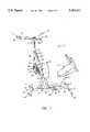
- FIG. 1is a perspective drawing showing a stationary standing aid.
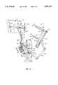
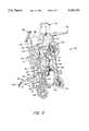
- FIG. 2is a perspective drawing showing the hydraulic lift and seat/hip support.
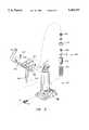
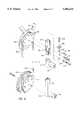
- FIG. 3is a perspective drawing of the hydraulic pump assembly.
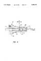
- FIG. 4is a cross-section drawing of an axially directed hydraulic relief valve.
- FIG. 5is a perspective drawing of a mobile, hand driven standing aid.
- FIG. 6is a perspective drawing of the hand drive linkage assembly.
- FIG. 7is a perspective drawing, shown in partial cutaway, of a detachable accessory basket which is useable with either support assembly.
- FIGS. 1 and 2perspective drawings are shown of a portable standing aid 2.
- the aid 2is constructed of a base 4, a vertical support column 6 and a tabletop or working platform 8, which may also be used to support a user's elbows.
- the column 6is secured to the base 4 at a gusset bracket. Telescoping from beneath the table 8 is a padded chest support 10.
- a leg support 12is secured to the column 6, along with a pivoting, hydraulically controlled seat/hip support 14.
- the base frame 4includes a telescoping longitudinal frame piece 16. Fore and aft stabilizers 18 and 20 transversely project from the longitudinal member 16. A pair of wheels 19 project from axle brackets 21 that are permanently secured to the stabilizer 18 and which permit manual transport of the assembly 2. That is, upon grasping and rotating the support column 6 forward, the weight of the assembly 2 is shifted onto the wheels 19, which raises the stabilizer 18 and permits a user or an attendant to move the assembly 2.
- the base frame 4occupies a space of approximately 29 ⁇ 36 inches.
- the stabilizer 20 and/or 18, depending upon the construction,includes multiple, height adjustable support pads 23.
- a surface material of the pads 23can be varied to the ground condition.
- the pad materialprevents movement of the base 4 during use of the assembly 2.
- the frame piece 16includes a pair of tubular pieces 24 and 26 which telescope from one another. An appropriate length of the frame piece 16 is established with a clamping foot or heel stop 28 which mounts over the frame piece 26. A cooperating threaded draw fastener 30 mounts through the stop 28 to compressively fix a desired length.
- the stabilizers 18 and/or 20can be made length adjustable.
- the position of the stop 28can also be adjusted along the frame piece 26 to accommodate the feet.
- a pair of formed wing pieces 32 and 34transversely project from the stop 28 to contact and restrain the user's heels.
- the wing members 32, 34particularly prevent the user's feet from slipping backward to maintain a stable foot position, during lifting and once the user is fully erect and the legs are supported to the leg support 12.
- the tabletop 8is constructed of a platform 40 which is secured to a tubular H-shaped frame 42.
- the platform 40can be constructed to any size and of any variety of materials. Presently a 16 ⁇ 24 inch surface is provided which is constructed from a 3/8" thick acrylic stock.
- a member 44telescopes from a cross piece 46 of the frame 42.
- a padded chest support 48telescopes from the member 44.
- the relative mounting position or displacement of the pad 48 from the platform 40is determined via a clamp 50.
- a vertical adjustmentmay also be provided at the member 44, although is not presently required due to the adjustable nature of the column 6, described below.
- the chest support 10is presently constructed to be extensible over a range of approximately 3 to 6 inches.
- the support 10provides a support surface of approximately 7 ⁇ 12 inches and is approximately one inch thick.
- the support column 6includes a base piece 52 and a telescoping extension piece 54.
- the base piece 52is secured to the longitudinal member 16 at a gusset bracket.
- a number of holes 56 in the extension piece 54selectively establish the extension of the support 6 relative to the base 4 at a threaded fastener 58 and mating retainer.
- a compressive clamp actionis obtained with the fastener 58.
- the height of the column 6is adjustable over an approximate range of 40 to 52 inches.
- the leg support 12is adjustably secured to the column piece 52 at a bracket 68 with appropriate bolt fasteners 70.
- the bracket 68is welded to the column 52, although may be mounted to a clamp or at apertures 72 to permit adjustment of the leg support 12 along the column piece 52.
- a leg support cushion 74is mounted to the bracket 68 and provides a contoured 10 ⁇ 16 inch padded surface.
- the forward face of the surfaceincludes a pair of vertical channels 78.
- the channels 78conform about the knee and shin region of the occupant's legs and laterally restrain movement of the legs.
- the lift 80Secured to the column 6, opposite the leg support 12, is a hydraulic lift assembly 80.
- the lift 80includes a hydraulic pump 82 and cantilevered lift arm 84.
- the pump 82comprises a so called “bottle jack” which has been modified to permit the supported user to manually raise and lower the lift arm 84. More of the details of the pump 82 are shown at FIGS. 3 and 4 and to which attention is also directed.
- a piston 88extends from a pump body 89 and is secured to an upper shackle 90 at the column piece 52 with a through bolt 92.
- the bolt 92extends through a bushing 91 secured to the end of the piston 88.
- the shackle 90anchors the pump 82 to the assembly 2.
- the pump body 89is secured to a plate 94 at one end of the lift arm 84. Extension and retraction of the piston 88 rotates the arm 84. Rotation is determined with a tubular pump handle 98 that extends to a preferred side of the column 6.
- the handle 98can be mounted to accommodate either right or left hand operation.
- the handle 98is also shaped to facilitate a manual pump action by the occupant in either a seated or standing posture.
- the pump 82provides a range of extension from 0 to 5 inches. In combination with the depicted shape of the arm 84, the pump 82 permits rotation of the arm 84 to vary the position of the seat/hip support 14 between a fully lowered horizontal orientation to a fully raised vertical orientation and to transport the occupant from a seated to a standing posture.
- the handle 98mounts to a pivot rod 250 that rotates in a pair of link arms 252, 254 that are welded to the pump body 89.
- a pin fastener 257restrains the handle 98 to an appropriate side of the rod 250.
- a pump actuator 256is welded to the rod 250 and engages a spring biased assembly 258 which establishes a neutral position at the pump 82.
- the assembly 258includes a valve stem or plunger 260 and to which O'ring seals 261 are secured.
- the plunger 260mounts inside a valve body 262 which is threaded to the pump body 89. Movement of the plunger 260 appropriately directs fluid in the pump body 89 to extend the pump piston 88.
- a cap piece 262is secured to the upper end of the plunger 260 with a threaded fastener 263.
- the cap piece 262retains a spring 264 between the body 89 and the actuator arm 256, and the arm 256 contacts the end of the fastener 261 and/or end of the plunger 260.
- the spring 264counters the motion and biases the handle 98 to the neutral position.
- Pushing on the handle 98induces a linkage arm 258, which is also welded to the rod 250, to depress a relief valve 99 and direct fluid in the pump body 89 to permit the arm 84 to descend.
- the rate of descentcan be varied by jogging the handle 98 into and out of engagement with the valve 99. Modifications have also been provided to the relief valve 99 to control or slow the rate of descent, which modifications are discussed in greater detail below with reference to FIG. 4.
- an axial, push action relief valve 99is provided.
- a plunger or valve stem 270is biased by a spring 272 which mounts within a valve body 274.
- the plunger 270manipulates a ball check 276 which is biased in a bore 278 of the body 274 by a second spring 280.
- liquidcan pass from the piston cylinder to the reservoir at the pump body 89 via a port 284.
- the volume of liquidis partially reduced by a slot 286 in the outer surface of the body 274 which re-directs a portion of the fluid flow in a closed loop. The re-direction of a portion of the fluid reduces the rate of descent of the arm 84.
- the collar 100includes an extension piece 101 which is welded to the column piece 52, and which offsets a pivot bushing (not shown) that is welded to an upper surface of the extension 101.
- a pair of plates 102, 104extend from the arm 84 and are secured to the pivot bushing with a through fastener 106.
- Another fastener 107secures the ends of the plates 102, 104 on the opposite side of the column piece 52 to the base plate 94 and the pump 82.
- the piston 88extends and retracts with the user directed motion of the handle 98, the arm 84 rotates about the fastener 106.
- the pivot arm 84is constructed of three tubular pieces 110, 112 and 114.
- the piece 110projects from the plates 102, 104 to the piece 112 at an approximate angular orientation in the range of 80 to 90 degrees.
- the piece 114projects from the piece 112 at an angular orientation in the range of 100 to 120 degrees.
- a seat frame 116is rigidly secured to the end of the piece 114 and a padded cushion 118 is appended to the frame 116.
- a pair of hip or wing supports 120, 122project from the seat frame 116.
- the wing supports 120, 122are each pivotally secured to the frame 116 at a retained fastener 124.
- a padded collar 126mounts about a rigid core piece 128 of each wing 120, 122.
- each wing support 120, 122can be rotated parallel to the seat frame 116 to facilitate user access to the assembly 2.
- each wing support 120, 122is normally rotated, as depicted, to engage or restrain the hip region of the occupant. Minimal contact is made with the occupant.
- the assemblies 120, 122laterally stabilize the occupant, as necessary, who is otherwise also stabilized via the chest support 10, leg support 12 and heel restraint 28.
- FIGS. 5 and 6an alternative, mobile standing assembly 150 is shown.
- the assembly 150is substantially similar to the assembly 2 with the exception of appropriate modifications to provide independent, manual drive linkages 152 and 154 to each of a pair of drive wheels 156 and 158. More of the details of the drive assemblies 152 and 154 are described with respect to FIG. 6.
- a base frame 160includes a fixed length longitudinal member 162 and fore and aft stabilizers 164 and 166. If desired, the member 162 and/or stabilizers 164, 166 can be constructed to telescope, as described above for the member 16.
- a pair of casters 168which are rotatable at horizontal and vertical axes, project from the aft stabilizer 166. Depending upon the ground surface, the type of casters 168 can be varied. Commercially available furniture casters are presently used.
- An elevated, molded foot restraint 169is fastened along the member 162 with appropriate fasteners (not shown).
- the restraint 169provides conformal foot pads 170 having integral heel restraints 171.
- the position of the foot restraint 169 along the member 162can be adjusted to provide proper weight distribution to stabilize the assembly 150 and the occupant under stationary and moving conditions.
- the support column 172projects from the member 162 to a working platform 174.
- the height of the platform 174can be adjusted at a threaded hand fastener 173, which mates with holes in the vertical support column 172.
- a padded chest support 176telescopes from beneath the platform 174.
- the support 176is contoured to provide upper trunk stability and contact a greater area of the thoracic cavity than the assembly 2.
- a leg restraint 180is secured to the column 172.
- the restraint 180is substantially similar to the leg restraint 12 and provides a pair of conformal vertical channels to capture the knee/shin areas of the occupant's legs.
- a seat/hip support assembly 182which is substantially similar to the assembly 14.
- a pair of pivoting wing arms 188mount to the seat platform 183.
- the chest support 176, leg restraint 180, seat platform 183, wing arms 188 and foot restraint 169confine the occupant to the assembly 150, once the seat/hip support 182 is fully raised to place the occupant in an erect position.
- a utility basket 200shown in partial cutaway at FIG. 7, is secured to the column 172 at a stub piece 210 which projects from the column 172.
- U-shaped portions 204 of the basketrestrain the basket 200 to the stub piece 202.
- the vertical position of the seat support 182is determined by a pump handle 210 which operates in relation to a hydraulic pump 212. Operation of the handle 210 induces an extension and retraction of a piston 213, which action raises and lowers the seat platform 183.
- Mobilityis obtained with the hand wheels 153, 155, which cooperate with the drive wheels 156, 158 and drive linkage assemblies 152, 154.
- FIG. 6depicts various details of the independent drive assemblies 152 and 154.
- the drive linkages 152, 154are supported to a pair of vertical frame members 219, 221.
- a cross frame member 151is welded to the upper ends of the members 219, 221 and the cross member 151 is fastened to the column 172 at a clamp plate 221.
- a lower end of the drives 152, 154is secured to the stabilizer 164, which is fastened to the column 172.
- each drive 152, 154is identical to the other.
- the drive 154 versus the drive 152is depicted and described in detail only as a matter of convenience.
- the drive wheel 156 and the tubular frame member 219are secured to the stabilizer 164 at an offset plate 220.
- the plate 220is welded to the end of the stabilizer 164.
- An axle bolt 222mounts through the plate 220, wheel 158 and frame member 219.
- a V-belt pulley 224is permanently secured to the back of the wheel 156 and rotates in unison with the wheel 156. Spacers, bearings or bushings (not shown) are provided to assure smooth rotation of the wheel 158.
- a second V-pulley 226is permanently secured to an inside surface of the hand wheel 155.
- the hand wheel 155is secured to the frame member 219 with a smooth shouldered axle bolt 228.
- the bolt 228mounts within slots 230, 231 formed into the member 219.
- the slots 230, 231also receive a detent 232.
- the detent 232includes a spring biased, locking or latch pin 234 which selectively mates with one of a number of apertures 236 at the back of the pulley 226. That is, once the assembly 150 is manually maneuvered to a desired location, upon engaging the detent 232, the pin 234 is extended and latched to the pulley 226 to restrain further movement.
- a drive belt 237extends between the pulleys 224 and 226.
- the mounting of the pulleys 224 and 226 to the member 219assures a proper vertical alignment of one to the other, and minimizes tracking difficulties with the belt 237.
- Proper belt tensionis established with a tensioner 238 which cooperates with the slots 230, 231.
- the tensioner 238includes a captured bushing 240.
- Apertures 242, 244laterally extend through the side of the bushing 240 and receive the stub axle 228 and detent 232.
- the bushing 240mounts inside the frame member 219 and is free to move up and down in relation to movement of a threaded adjuster 242 that mates with a longitudinal bore 244 of the bushing 240 and a cap piece 246.
- the cap piece 246rigidly mounts to the end of the member 219. Upon appropriately rotating the adjuster 242, the bushing 240, stub axle 234 and detent 232 are raised or lowered to provide a desired tension at the drive belt 232.
Landscapes
- Health & Medical Sciences (AREA)
- Life Sciences & Earth Sciences (AREA)
- Animal Behavior & Ethology (AREA)
- General Health & Medical Sciences (AREA)
- Public Health (AREA)
- Veterinary Medicine (AREA)
- Invalid Beds And Related Equipment (AREA)
Abstract
Description
Claims (23)
Priority Applications (1)
| Application Number | Priority Date | Filing Date | Title |
|---|---|---|---|
| US08/154,608US5484151A (en) | 1993-11-18 | 1993-11-18 | Mobile standing aid |
Applications Claiming Priority (1)
| Application Number | Priority Date | Filing Date | Title |
|---|---|---|---|
| US08/154,608US5484151A (en) | 1993-11-18 | 1993-11-18 | Mobile standing aid |
Publications (1)
| Publication Number | Publication Date |
|---|---|
| US5484151Atrue US5484151A (en) | 1996-01-16 |
Family
ID=22552013
Family Applications (1)
| Application Number | Title | Priority Date | Filing Date |
|---|---|---|---|
| US08/154,608Expired - LifetimeUS5484151A (en) | 1993-11-18 | 1993-11-18 | Mobile standing aid |
Country Status (1)
| Country | Link |
|---|---|
| US (1) | US5484151A (en) |
Cited By (25)
| Publication number | Priority date | Publication date | Assignee | Title |
|---|---|---|---|---|
| GB2307666A (en)* | 1994-10-03 | 1997-06-04 | Brian J Nestor | Mobile standing aid |
| US5829766A (en)* | 1992-11-14 | 1998-11-03 | Irmgard Gohlert | Device for dressing and undressing and for the cleaning and care of the body of a handicapped person |
| US5860899A (en)* | 1996-10-07 | 1999-01-19 | New Back Technologies, L.L.C. | Back manipulating apparatus |
| US5884935A (en)* | 1997-06-09 | 1999-03-23 | Tholkes; Alan L. | Modular standing support |
| WO1999026579A1 (en)* | 1997-11-21 | 1999-06-03 | Marec Hase | Mobile standing device for use in rehabilitation |
| US6231067B1 (en) | 1998-01-12 | 2001-05-15 | Fena Design, Inc. | Motorized standing wheelchair |
| US6439657B1 (en) | 1999-02-25 | 2002-08-27 | Alan L. Tholkes | Synergistic body positioning and dynamic support system |
| US6440046B1 (en)* | 1998-11-17 | 2002-08-27 | Altimate Medical, Inc. | Disabled user lift system |
| US6644748B2 (en) | 1999-02-25 | 2003-11-11 | Health Postures, Inc. | Synergistic body positioning and dynamic support system |
| US6698831B2 (en)* | 2000-07-20 | 2004-03-02 | John T. Lloyd | Adjustable chair |
| US20050035644A1 (en)* | 2001-12-14 | 2005-02-17 | Lloyd John T. | Portable massage chair |
| US7036512B2 (en) | 2003-06-25 | 2006-05-02 | Prodije 9061-7457 Quebec Inc. | Dismountable multi-position stander |
| US20060097557A1 (en)* | 2004-10-12 | 2006-05-11 | Tholkes Alan L | Modular standing frame |
| US20060220429A1 (en)* | 2003-05-05 | 2006-10-05 | Par Nylander | Patient chair with a vertically movable seat |
| US20070086880A1 (en)* | 2005-10-14 | 2007-04-19 | Mark Jordan | Personal lift apparatus |
| US20070270295A1 (en)* | 2005-10-04 | 2007-11-22 | Anastasios Balis | Extensor muscle based postural rehabilitation systems and methods with integrated multimedia therapy and instructional components |
| US20090146389A1 (en)* | 2005-03-30 | 2009-06-11 | Jaimie Borisoff | Wheelchair |
| US20090186747A1 (en)* | 2008-01-22 | 2009-07-23 | Invacare Corporation | Seat |
| KR100921970B1 (en)* | 2009-01-09 | 2009-10-19 | 김병일 | bathchair |
| US20100007180A1 (en)* | 2008-07-08 | 2010-01-14 | Invacare Corporation | Standing Frame with Supine Mode |
| US9844868B1 (en) | 2014-01-27 | 2017-12-19 | Kenneth Robert Abbey | Cart system for tool manipulation |
| US10493349B2 (en) | 2016-03-18 | 2019-12-03 | Icon Health & Fitness, Inc. | Display on exercise device |
| US10625114B2 (en) | 2016-11-01 | 2020-04-21 | Icon Health & Fitness, Inc. | Elliptical and stationary bicycle apparatus including row functionality |
| US10625137B2 (en) | 2016-03-18 | 2020-04-21 | Icon Health & Fitness, Inc. | Coordinated displays in an exercise device |
| RU2779360C1 (en)* | 2021-08-17 | 2022-09-06 | Олег Владимирович Козелков | Method for verticalisation of a patient and apparatus for implementation thereof |
Citations (9)
| Publication number | Priority date | Publication date | Assignee | Title |
|---|---|---|---|---|
| US4732402A (en)* | 1985-09-13 | 1988-03-22 | Establissements Poirier | Wheelchair for a disabled person, particularly a child |
| US4744578A (en)* | 1987-02-09 | 1988-05-17 | Luconex, Inc. | User inclinable prone stander type wheelchair |
| US4861059A (en)* | 1988-04-22 | 1989-08-29 | Shirk Lynn V | Holder apparatus attachable on a wheelchair for holding a catheter bag and the like |
| US4968050A (en)* | 1988-10-11 | 1990-11-06 | Luconex, Inc. | Mobile prone stander having adjustable axis of inclination |
| US5172925A (en)* | 1989-06-09 | 1992-12-22 | Quickie Designs Inc. | Mobile prone stander with positioning chair |
| US5242180A (en)* | 1992-06-01 | 1993-09-07 | Bergeron Timothy J | Prone stander |
| US5265689A (en)* | 1991-01-14 | 1993-11-30 | Kauffmann Ricardo M | Prosthetic device for lifting and lowering a person thereon |
| US5294027A (en)* | 1993-02-25 | 1994-03-15 | Bel-Art Products, Inc. | Portable combination table top/basket apparatus |
| US5340139A (en)* | 1993-01-11 | 1994-08-23 | Davis Daniel W | Ambulatory wheelstand with torso and leg support |
- 1993
- 1993-11-18USUS08/154,608patent/US5484151A/ennot_activeExpired - Lifetime
Patent Citations (9)
| Publication number | Priority date | Publication date | Assignee | Title |
|---|---|---|---|---|
| US4732402A (en)* | 1985-09-13 | 1988-03-22 | Establissements Poirier | Wheelchair for a disabled person, particularly a child |
| US4744578A (en)* | 1987-02-09 | 1988-05-17 | Luconex, Inc. | User inclinable prone stander type wheelchair |
| US4861059A (en)* | 1988-04-22 | 1989-08-29 | Shirk Lynn V | Holder apparatus attachable on a wheelchair for holding a catheter bag and the like |
| US4968050A (en)* | 1988-10-11 | 1990-11-06 | Luconex, Inc. | Mobile prone stander having adjustable axis of inclination |
| US5172925A (en)* | 1989-06-09 | 1992-12-22 | Quickie Designs Inc. | Mobile prone stander with positioning chair |
| US5265689A (en)* | 1991-01-14 | 1993-11-30 | Kauffmann Ricardo M | Prosthetic device for lifting and lowering a person thereon |
| US5242180A (en)* | 1992-06-01 | 1993-09-07 | Bergeron Timothy J | Prone stander |
| US5340139A (en)* | 1993-01-11 | 1994-08-23 | Davis Daniel W | Ambulatory wheelstand with torso and leg support |
| US5294027A (en)* | 1993-02-25 | 1994-03-15 | Bel-Art Products, Inc. | Portable combination table top/basket apparatus |
Cited By (40)
| Publication number | Priority date | Publication date | Assignee | Title |
|---|---|---|---|---|
| US5829766A (en)* | 1992-11-14 | 1998-11-03 | Irmgard Gohlert | Device for dressing and undressing and for the cleaning and care of the body of a handicapped person |
| GB2307666A (en)* | 1994-10-03 | 1997-06-04 | Brian J Nestor | Mobile standing aid |
| US5860899A (en)* | 1996-10-07 | 1999-01-19 | New Back Technologies, L.L.C. | Back manipulating apparatus |
| US5884935A (en)* | 1997-06-09 | 1999-03-23 | Tholkes; Alan L. | Modular standing support |
| WO1999026579A1 (en)* | 1997-11-21 | 1999-06-03 | Marec Hase | Mobile standing device for use in rehabilitation |
| US6270101B1 (en) | 1997-11-21 | 2001-08-07 | Marec Hase | Mobile standing device for use in rehabilitation |
| US6231067B1 (en) | 1998-01-12 | 2001-05-15 | Fena Design, Inc. | Motorized standing wheelchair |
| US6440046B1 (en)* | 1998-11-17 | 2002-08-27 | Altimate Medical, Inc. | Disabled user lift system |
| EP1139967A4 (en)* | 1998-11-17 | 2003-08-06 | Altimate Medical Inc | Disabled user lift system |
| US6644748B2 (en) | 1999-02-25 | 2003-11-11 | Health Postures, Inc. | Synergistic body positioning and dynamic support system |
| US6702372B2 (en) | 1999-02-25 | 2004-03-09 | Health Postures, Inc. | Synergistic body positioning and dynamic support system |
| US6726276B1 (en) | 1999-02-25 | 2004-04-27 | Health Postures, Inc. | Synergistic body positioning and dynamic support system |
| US6439657B1 (en) | 1999-02-25 | 2002-08-27 | Alan L. Tholkes | Synergistic body positioning and dynamic support system |
| US6698831B2 (en)* | 2000-07-20 | 2004-03-02 | John T. Lloyd | Adjustable chair |
| US7144080B2 (en) | 2001-12-14 | 2006-12-05 | Lloyd John T | Portable massage chair |
| US20050035644A1 (en)* | 2001-12-14 | 2005-02-17 | Lloyd John T. | Portable massage chair |
| US7273255B2 (en)* | 2003-05-05 | 2007-09-25 | Arjo Hospital Equipment Ab | Patient chair with a vertically movable seat |
| US20060220429A1 (en)* | 2003-05-05 | 2006-10-05 | Par Nylander | Patient chair with a vertically movable seat |
| US7036512B2 (en) | 2003-06-25 | 2006-05-02 | Prodije 9061-7457 Quebec Inc. | Dismountable multi-position stander |
| US20100013276A1 (en)* | 2004-10-12 | 2010-01-21 | Altimate Medical, Inc. | Modular standing frame |
| US20060097557A1 (en)* | 2004-10-12 | 2006-05-11 | Tholkes Alan L | Modular standing frame |
| US8567808B2 (en) | 2004-10-12 | 2013-10-29 | Altimate Medical, Inc. | Modular standing frame |
| US7614639B2 (en) | 2004-10-12 | 2009-11-10 | Invacare Corporation | Modular standing frame |
| US20090146389A1 (en)* | 2005-03-30 | 2009-06-11 | Jaimie Borisoff | Wheelchair |
| US7845665B2 (en) | 2005-03-30 | 2010-12-07 | Jaimie Borisoff | Wheelchair |
| US20070270295A1 (en)* | 2005-10-04 | 2007-11-22 | Anastasios Balis | Extensor muscle based postural rehabilitation systems and methods with integrated multimedia therapy and instructional components |
| US7635324B2 (en)* | 2005-10-04 | 2009-12-22 | Anastasios Balis | Extensor muscle based postural rehabilitation systems and methods with integrated multimedia therapy and instructional components |
| US20070086880A1 (en)* | 2005-10-14 | 2007-04-19 | Mark Jordan | Personal lift apparatus |
| US8388505B2 (en) | 2008-01-22 | 2013-03-05 | Invacare Corp. | Seat |
| US8123664B2 (en) | 2008-01-22 | 2012-02-28 | Invacare Corp. | Seat |
| US20090186747A1 (en)* | 2008-01-22 | 2009-07-23 | Invacare Corporation | Seat |
| US9079089B2 (en) | 2008-01-22 | 2015-07-14 | Altimate Medical, Inc. | Seat |
| US20100007180A1 (en)* | 2008-07-08 | 2010-01-14 | Invacare Corporation | Standing Frame with Supine Mode |
| US8104835B2 (en) | 2008-07-08 | 2012-01-31 | Invacare Corp. | Standing frame with supine mode |
| KR100921970B1 (en)* | 2009-01-09 | 2009-10-19 | 김병일 | bathchair |
| US9844868B1 (en) | 2014-01-27 | 2017-12-19 | Kenneth Robert Abbey | Cart system for tool manipulation |
| US10493349B2 (en) | 2016-03-18 | 2019-12-03 | Icon Health & Fitness, Inc. | Display on exercise device |
| US10625137B2 (en) | 2016-03-18 | 2020-04-21 | Icon Health & Fitness, Inc. | Coordinated displays in an exercise device |
| US10625114B2 (en) | 2016-11-01 | 2020-04-21 | Icon Health & Fitness, Inc. | Elliptical and stationary bicycle apparatus including row functionality |
| RU2779360C1 (en)* | 2021-08-17 | 2022-09-06 | Олег Владимирович Козелков | Method for verticalisation of a patient and apparatus for implementation thereof |
Similar Documents
| Publication | Publication Date | Title |
|---|---|---|
| US5484151A (en) | Mobile standing aid | |
| US5884935A (en) | Modular standing support | |
| US5054852A (en) | Utility station with controlled seating | |
| US4915378A (en) | Exercising apparatus | |
| US5038758A (en) | User controlled device for decompressing the spine | |
| US6354982B1 (en) | Exercise machine and methods | |
| EP2311425B1 (en) | Modular standing frame with movable work surface | |
| US10018298B2 (en) | Exercise machine and method for use in a supine position | |
| US4465274A (en) | Hydraulic exercise device | |
| US8151812B2 (en) | Sit down and stand up walker with seat assembly | |
| US5807219A (en) | Exercise apparatus adaptable for handicapped and non-handicapped users | |
| US8033971B2 (en) | Adjustable user support platform for an inclinable exercise device and method of use | |
| KR100995230B1 (en) | Fitness equipment | |
| US5509880A (en) | Apparatus for exercise, body stretching, neuromuscular and other orthopedic movements | |
| US5005829A (en) | Exercise machine for patients confined to bed | |
| US20080153677A1 (en) | Leg press exercise machine with self-aligning pivoting seat | |
| US20090286658A1 (en) | Multi-Angle Incline Dumbbell Bench Press | |
| WO2001030458A1 (en) | Backstrong lumbar extension machine | |
| US5556363A (en) | Linear movement, trunk muscle exercise method | |
| WO2005076746A2 (en) | Back traction and muscle stretching bench | |
| EP0456718A1 (en) | Combination wheelchair and walker apparatus | |
| US20190015695A1 (en) | Inclined reverse hyperextension exercise device | |
| US5507711A (en) | Leg stretcher | |
| US5980434A (en) | Exercise apparatus with adjustable roller pads | |
| US7153251B2 (en) | Stretching apparatus |
Legal Events
| Date | Code | Title | Description |
|---|---|---|---|
| STCF | Information on status: patent grant | Free format text:PATENTED CASE | |
| FPAY | Fee payment | Year of fee payment:4 | |
| AS | Assignment | Owner name:NEW LIFE CORPORATION OF AMERICA, TENNESSEE Free format text:ASSIGNMENT OF ASSIGNORS INTEREST;ASSIGNOR:THOLKES, ALAN L.;REEL/FRAME:013323/0071 Effective date:20021231 | |
| AS | Assignment | Owner name:ALTIMATE MEDICAL, INC., MINNESOTA Free format text:ASSIGNMENT OF ASSIGNORS INTEREST;ASSIGNOR:NEW LIFE CORPORATION OF AMERICA;REEL/FRAME:013740/0695 Effective date:20030203 | |
| FPAY | Fee payment | Year of fee payment:8 | |
| FEPP | Fee payment procedure | Free format text:PAT HOLDER NO LONGER CLAIMS SMALL ENTITY STATUS, ENTITY STATUS SET TO UNDISCOUNTED (ORIGINAL EVENT CODE: STOL); ENTITY STATUS OF PATENT OWNER: LARGE ENTITY | |
| REFU | Refund | Free format text:REFUND - PAYMENT OF MAINTENANCE FEE, 12TH YR, SMALL ENTITY (ORIGINAL EVENT CODE: R2553); ENTITY STATUS OF PATENT OWNER: LARGE ENTITY | |
| AS | Assignment | Owner name:NATIONAL CITY BANK, AS MULTICURRENCY COLLATERAL AG Free format text:NOTICE OF GRANT OF SECURITY INTEREST;ASSIGNOR:ALTIMATE MEDICAL, INC.;REEL/FRAME:019000/0793 Effective date:20070212 | |
| FPAY | Fee payment | Year of fee payment:12 | |
| SULP | Surcharge for late payment | Year of fee payment:11 | |
| FEPP | Fee payment procedure | Free format text:ENTITY STATUS SET TO UNDISCOUNTED (ORIGINAL EVENT CODE: BIG.); ENTITY STATUS OF PATENT OWNER: LARGE ENTITY | |
| AS | Assignment | Owner name:PNC BANK, NATIONAL ASSOCIATION, PENNSYLVANIA Free format text:SECURITY AGREEMENT;ASSIGNORS:INVACARE CORPORATION;ADAPTIVE SWITCH LABORATORIES, INC.;THE AFTERMARKET GROUP, INC.;AND OTHERS;REEL/FRAME:025473/0311 Effective date:20101028 | |
| AS | Assignment | Owner name:ALTIMATE MEDICAL, INC., OHIO Free format text:RELEASE OF SECURITY INTEREST;ASSIGNOR:PNC BANK, NATIONAL ASSOCIATION;REEL/FRAME:033673/0551 Effective date:20140829 Owner name:INVACARE CORPORATION, OHIO Free format text:RELEASE OF SECURITY INTEREST;ASSIGNOR:PNC BANK, NATIONAL ASSOCIATION;REEL/FRAME:033673/0551 Effective date:20140829 | |
| AS | Assignment | Owner name:INVACARE HCS, LLC, OHIO Free format text:RELEASE BY SECURED PARTY;ASSIGNOR:PNC BANK, NATIONAL ASSOCIATION;REEL/FRAME:063668/0679 Effective date:20230505 Owner name:INVACARE FLORIDA HOLDINGS, LLC, OHIO Free format text:RELEASE BY SECURED PARTY;ASSIGNOR:PNC BANK, NATIONAL ASSOCIATION;REEL/FRAME:063668/0679 Effective date:20230505 Owner name:GARDEN CITY MEDICAL INC., OHIO Free format text:RELEASE BY SECURED PARTY;ASSIGNOR:PNC BANK, NATIONAL ASSOCIATION;REEL/FRAME:063668/0679 Effective date:20230505 Owner name:FREEDOM DESIGNS, INC., OHIO Free format text:RELEASE BY SECURED PARTY;ASSIGNOR:PNC BANK, NATIONAL ASSOCIATION;REEL/FRAME:063668/0679 Effective date:20230505 Owner name:ROADRUNNER MOBILITY, INCORPORATED, OHIO Free format text:RELEASE BY SECURED PARTY;ASSIGNOR:PNC BANK, NATIONAL ASSOCIATION;REEL/FRAME:063668/0679 Effective date:20230505 Owner name:KUSCHALL, INC., OHIO Free format text:RELEASE BY SECURED PARTY;ASSIGNOR:PNC BANK, NATIONAL ASSOCIATION;REEL/FRAME:063668/0679 Effective date:20230505 Owner name:INVAMEX HOLDINGS LLC, OHIO Free format text:RELEASE BY SECURED PARTY;ASSIGNOR:PNC BANK, NATIONAL ASSOCIATION;REEL/FRAME:063668/0679 Effective date:20230505 Owner name:INVACARE SUPPLY GROUP, INC., OHIO Free format text:RELEASE BY SECURED PARTY;ASSIGNOR:PNC BANK, NATIONAL ASSOCIATION;REEL/FRAME:063668/0679 Effective date:20230505 Owner name:INVACARE INTERNATIONAL CORPORATION, OHIO Free format text:RELEASE BY SECURED PARTY;ASSIGNOR:PNC BANK, NATIONAL ASSOCIATION;REEL/FRAME:063668/0679 Effective date:20230505 Owner name:INVACARE HOLDINGS, LLC, OHIO Free format text:RELEASE BY SECURED PARTY;ASSIGNOR:PNC BANK, NATIONAL ASSOCIATION;REEL/FRAME:063668/0679 Effective date:20230505 Owner name:INVACARE FLORIDA CORPORATION, OHIO Free format text:RELEASE BY SECURED PARTY;ASSIGNOR:PNC BANK, NATIONAL ASSOCIATION;REEL/FRAME:063668/0679 Effective date:20230505 Owner name:INVACARE CREDIT CORPORATION, OHIO Free format text:RELEASE BY SECURED PARTY;ASSIGNOR:PNC BANK, NATIONAL ASSOCIATION;REEL/FRAME:063668/0679 Effective date:20230505 Owner name:INVACARE CONTINUING CARE, INC., OHIO Free format text:RELEASE BY SECURED PARTY;ASSIGNOR:PNC BANK, NATIONAL ASSOCIATION;REEL/FRAME:063668/0679 Effective date:20230505 Owner name:INVACARE CANADIAN HOLDINGS, LLC, OHIO Free format text:RELEASE BY SECURED PARTY;ASSIGNOR:PNC BANK, NATIONAL ASSOCIATION;REEL/FRAME:063668/0679 Effective date:20230505 Owner name:INVACARE CANADIAN HOLDINGS, INC., OHIO Free format text:RELEASE BY SECURED PARTY;ASSIGNOR:PNC BANK, NATIONAL ASSOCIATION;REEL/FRAME:063668/0679 Effective date:20230505 Owner name:THE HELIXX GROUP, INC., OHIO Free format text:RELEASE BY SECURED PARTY;ASSIGNOR:PNC BANK, NATIONAL ASSOCIATION;REEL/FRAME:063668/0679 Effective date:20230505 Owner name:FAMILY MEDICAL SUPPLY LLC, OHIO Free format text:RELEASE BY SECURED PARTY;ASSIGNOR:PNC BANK, NATIONAL ASSOCIATION;REEL/FRAME:063668/0679 Effective date:20230505 Owner name:CHAMPION MANUFACTURING INC., OHIO Free format text:RELEASE BY SECURED PARTY;ASSIGNOR:PNC BANK, NATIONAL ASSOCIATION;REEL/FRAME:063668/0679 Effective date:20230505 Owner name:CENTRALIZED MEDICAL EQUIPMENT LLC, OHIO Free format text:RELEASE BY SECURED PARTY;ASSIGNOR:PNC BANK, NATIONAL ASSOCIATION;REEL/FRAME:063668/0679 Effective date:20230505 Owner name:ALTIMATE MEDICAL, INC., OHIO Free format text:RELEASE BY SECURED PARTY;ASSIGNOR:PNC BANK, NATIONAL ASSOCIATION;REEL/FRAME:063668/0679 Effective date:20230505 Owner name:THE AFTERMARKET GROUP, INC., OHIO Free format text:RELEASE BY SECURED PARTY;ASSIGNOR:PNC BANK, NATIONAL ASSOCIATION;REEL/FRAME:063668/0679 Effective date:20230505 Owner name:ADAPTIVE SWITCH LABORATORIES, INC., OHIO Free format text:RELEASE BY SECURED PARTY;ASSIGNOR:PNC BANK, NATIONAL ASSOCIATION;REEL/FRAME:063668/0679 Effective date:20230505 Owner name:INVACARE CORPORATION, OHIO Free format text:RELEASE BY SECURED PARTY;ASSIGNOR:PNC BANK, NATIONAL ASSOCIATION;REEL/FRAME:063668/0679 Effective date:20230505 Owner name:INVACARE HCS, LLC, OHIO Free format text:RELEASE BY SECURED PARTY;ASSIGNOR:PNC BANK, NATIONAL ASSOCIATION;REEL/FRAME:063662/0430 Effective date:20230505 Owner name:INVACARE FLORIDA HOLDINGS, LLC, OHIO Free format text:RELEASE BY SECURED PARTY;ASSIGNOR:PNC BANK, NATIONAL ASSOCIATION;REEL/FRAME:063662/0430 Effective date:20230505 Owner name:GARDEN CITY MEDICAL INC., OHIO Free format text:RELEASE BY SECURED PARTY;ASSIGNOR:PNC BANK, NATIONAL ASSOCIATION;REEL/FRAME:063662/0430 Effective date:20230505 Owner name:FREEDOM DESIGNS, INC., OHIO Free format text:RELEASE BY SECURED PARTY;ASSIGNOR:PNC BANK, NATIONAL ASSOCIATION;REEL/FRAME:063662/0430 Effective date:20230505 Owner name:ROADRUNNER MOBILITY, INCORPORATED, OHIO Free format text:RELEASE BY SECURED PARTY;ASSIGNOR:PNC BANK, NATIONAL ASSOCIATION;REEL/FRAME:063662/0430 Effective date:20230505 Owner name:KUSCHALL, INC., OHIO Free format text:RELEASE BY SECURED PARTY;ASSIGNOR:PNC BANK, NATIONAL ASSOCIATION;REEL/FRAME:063662/0430 Effective date:20230505 Owner name:INVAMEX HOLDINGS LLC, OHIO Free format text:RELEASE BY SECURED PARTY;ASSIGNOR:PNC BANK, NATIONAL ASSOCIATION;REEL/FRAME:063662/0430 Effective date:20230505 Owner name:INVACARE SUPPLY GROUP, INC., OHIO Free format text:RELEASE BY SECURED PARTY;ASSIGNOR:PNC BANK, NATIONAL ASSOCIATION;REEL/FRAME:063662/0430 Effective date:20230505 Owner name:INVACARE INTERNATIONAL CORPORATION, OHIO Free format text:RELEASE BY SECURED PARTY;ASSIGNOR:PNC BANK, NATIONAL ASSOCIATION;REEL/FRAME:063662/0430 Effective date:20230505 Owner name:INVACARE HOLDINGS, LLC, OHIO Free format text:RELEASE BY SECURED PARTY;ASSIGNOR:PNC BANK, NATIONAL ASSOCIATION;REEL/FRAME:063662/0430 Effective date:20230505 Owner name:INVACARE FLORIDA CORPORATION, OHIO Free format text:RELEASE BY SECURED PARTY;ASSIGNOR:PNC BANK, NATIONAL ASSOCIATION;REEL/FRAME:063662/0430 Effective date:20230505 Owner name:INVACARE CREDIT CORPORATION, OHIO Free format text:RELEASE BY SECURED PARTY;ASSIGNOR:PNC BANK, NATIONAL ASSOCIATION;REEL/FRAME:063662/0430 Effective date:20230505 Owner name:INVACARE CONTINUING CARE, INC., OHIO Free format text:RELEASE BY SECURED PARTY;ASSIGNOR:PNC BANK, NATIONAL ASSOCIATION;REEL/FRAME:063662/0430 Effective date:20230505 Owner name:INVACARE CANADIAN HOLDINGS, LLC, OHIO Free format text:RELEASE BY SECURED PARTY;ASSIGNOR:PNC BANK, NATIONAL ASSOCIATION;REEL/FRAME:063662/0430 Effective date:20230505 Owner name:INVACARE CANADIAN HOLDINGS, INC., OHIO Free format text:RELEASE BY SECURED PARTY;ASSIGNOR:PNC BANK, NATIONAL ASSOCIATION;REEL/FRAME:063662/0430 Effective date:20230505 Owner name:THE HELIXX GROUP, INC., OHIO Free format text:RELEASE BY SECURED PARTY;ASSIGNOR:PNC BANK, NATIONAL ASSOCIATION;REEL/FRAME:063662/0430 Effective date:20230505 Owner name:FAMILY MEDICAL SUPPLY LLC, OHIO Free format text:RELEASE BY SECURED PARTY;ASSIGNOR:PNC BANK, NATIONAL ASSOCIATION;REEL/FRAME:063662/0430 Effective date:20230505 Owner name:CHAMPION MANUFACTURING INC., OHIO Free format text:RELEASE BY SECURED PARTY;ASSIGNOR:PNC BANK, NATIONAL ASSOCIATION;REEL/FRAME:063662/0430 Effective date:20230505 Owner name:CENTRALIZED MEDICAL EQUIPMENT LLC, OHIO Free format text:RELEASE BY SECURED PARTY;ASSIGNOR:PNC BANK, NATIONAL ASSOCIATION;REEL/FRAME:063662/0430 Effective date:20230505 Owner name:ALTIMATE MEDICAL, INC., OHIO Free format text:RELEASE BY SECURED PARTY;ASSIGNOR:PNC BANK, NATIONAL ASSOCIATION;REEL/FRAME:063662/0430 Effective date:20230505 Owner name:THE AFTERMARKET GROUP, INC., OHIO Free format text:RELEASE BY SECURED PARTY;ASSIGNOR:PNC BANK, NATIONAL ASSOCIATION;REEL/FRAME:063662/0430 Effective date:20230505 Owner name:ADAPTIVE SWITCH LABORATORIES, INC., OHIO Free format text:RELEASE BY SECURED PARTY;ASSIGNOR:PNC BANK, NATIONAL ASSOCIATION;REEL/FRAME:063662/0430 Effective date:20230505 Owner name:INVACARE CORPORATION, OHIO Free format text:RELEASE BY SECURED PARTY;ASSIGNOR:PNC BANK, NATIONAL ASSOCIATION;REEL/FRAME:063662/0430 Effective date:20230505 |