US5483616A - Humidifier tank with improved handle - Google Patents
Humidifier tank with improved handleDownload PDFInfo
- Publication number
- US5483616A US5483616AUS08/360,473US36047394AUS5483616AUS 5483616 AUS5483616 AUS 5483616AUS 36047394 AUS36047394 AUS 36047394AUS 5483616 AUS5483616 AUS 5483616A
- Authority
- US
- United States
- Prior art keywords
- handle
- tank
- humidifier according
- humidifier
- tube
- Prior art date
- Legal status (The legal status is an assumption and is not a legal conclusion. Google has not performed a legal analysis and makes no representation as to the accuracy of the status listed.)
- Expired - Fee Related
Links
- XLYOFNOQVPJJNP-UHFFFAOYSA-NwaterSubstancesOXLYOFNOQVPJJNP-UHFFFAOYSA-N0.000claimsabstractdescription65
- 238000007599dischargingMethods0.000claimsdescription3
- 230000000717retained effectEffects0.000claims1
- 230000002093peripheral effectEffects0.000description6
- 238000010438heat treatmentMethods0.000description5
- 238000009835boilingMethods0.000description4
- 230000009471actionEffects0.000description2
- 230000007246mechanismEffects0.000description2
- 239000003595mistSubstances0.000description2
- 238000013021overheatingMethods0.000description2
- 230000037361pathwayEffects0.000description2
- 230000002745absorbentEffects0.000description1
- 239000002250absorbentSubstances0.000description1
- 230000000712assemblyEffects0.000description1
- 238000000429assemblyMethods0.000description1
- 230000006835compressionEffects0.000description1
- 238000007906compressionMethods0.000description1
- 230000007812deficiencyEffects0.000description1
- 238000001704evaporationMethods0.000description1
- 230000008020evaporationEffects0.000description1
- 239000000463materialSubstances0.000description1
- 238000000034methodMethods0.000description1
- 238000012986modificationMethods0.000description1
- 230000004048modificationEffects0.000description1
- 230000010355oscillationEffects0.000description1
- 230000008569processEffects0.000description1
- 230000000284resting effectEffects0.000description1
- 238000009987spinningMethods0.000description1
Images


Classifications
- F—MECHANICAL ENGINEERING; LIGHTING; HEATING; WEAPONS; BLASTING
- F24—HEATING; RANGES; VENTILATING
- F24F—AIR-CONDITIONING; AIR-HUMIDIFICATION; VENTILATION; USE OF AIR CURRENTS FOR SCREENING
- F24F6/00—Air-humidification, e.g. cooling by humidification
- F24F6/02—Air-humidification, e.g. cooling by humidification by evaporation of water in the air
- F24F6/04—Air-humidification, e.g. cooling by humidification by evaporation of water in the air using stationary unheated wet elements
- F24F6/043—Air-humidification, e.g. cooling by humidification by evaporation of water in the air using stationary unheated wet elements with self-sucking action, e.g. wicks
- F—MECHANICAL ENGINEERING; LIGHTING; HEATING; WEAPONS; BLASTING
- F24—HEATING; RANGES; VENTILATING
- F24F—AIR-CONDITIONING; AIR-HUMIDIFICATION; VENTILATION; USE OF AIR CURRENTS FOR SCREENING
- F24F2221/00—Details or features not otherwise provided for
- F24F2221/12—Details or features not otherwise provided for transportable
Definitions
- This inventionrelates generally to a portable humidifier and, more specifically, to a portable humidifier with an improved water tank.
- humidifiersare used to provide moisture to indoor air. Included among such humidifiers are ultrasonic humidifiers, steam humidifiers or vaporizers, and evaporative humidifiers.
- Ultrasonic humidifiersemploy a high-speed oscillator, positioned a given distance below the water surface, to energize the water and break it into a fine mist.
- a fancarries the mist into the surrounding environment. It is critical that the distance from the oscillator to the water level be accurately maintained to ensure that the oscillation energy is efficiently transferred to the water. A drop in water level can result in permanent damage to the oscillator.
- the water levelgenerally is maintained by the use of an inverted water tank such as that described in U.S. Pat. Nos. 5,210,818 and 5,247,604.
- the tankis sealed and includes a carrying handle on its top surface while a bottom surface includes an opening to which a cap is attached.
- the openingserves as a fill opening.
- the capincludes a valve system which seals the fill opening unless the tank is properly positioned on a humidifier base and the valve is engaged by a valve actuator in the base.
- the valve actuatoropens the valve and allows water to escape from the tank into a reservoir defined by the base. Discharging water is exchanged for air which enters the tank through the same opening. As water flows into the base reservoir, the water level rises until it seals the valve and prevents air from getting into the tank. At this level, which is the normal operating water level for the humidifier, water flow from the tank ceases.
- the design of the humidifieris established to position the oscillator that given distance below this level.
- the water levelattempts to drop creating a pathway for air into the tank and in turn allowing the release of a proportional amount of water from the tank into the reservoir to thereby return the water level to the normal operating level.
- This processrepeats itself continually until the water supply in the tank is depleted, at which time the water level begins to drop increasingly lower.
- a float sensing shut-off switch mechanismsenses the abnormally low water level and turns the humidifier off before the water level drops low enough to cause damage to the oscillator. This basic system is well known and often practiced in ultrasonic humidifiers of the prior art.
- Evaporative humidifierscome in several varieties. Some employ absorbent belts continuously rotating through first a water reservoir and then an air stream to cause humidity. Some employ pumps to lift water from a reservoir and pour it over a porous media through which air flows to cause similar humidification, and some employ wicking pads which are positioned partially below water level and partially above. In such humidifiers, the water level must be maintained for a different reason than that of the ultrasonic humidifier. Specifically, it is important that water level be maintained to ensure consistent humidity efficiency and maximum moisture output. Wick pads generally are capable of drawing water from the reservoir water level to a given height through capillary action. A relatively smaller portion of the wick pad must be positioned below the water level where water is absorbed, than above where air flowing through the pad causes the desired humidification.
- a submersible heating elementdepends from a humidification unit into a boiling chamber within a base.
- a water tank similar to that described aboveis positioned on the base to both feed water to the boiling chamber and to maintain a given normal operating level therein.
- the boiling watermaintains the temperature of the heating element at approximately two hundred and twelve degrees fahrenheit. It is important that the water level be maintained high enough to fully submerge the heating element, and not be allowed to drop while the heating element is energized or overheating will occur.
- a float sensing shut-off switch mechanismsenses an abnormally low water level as the water tank is depleted and turns the heating element off before excessive overheating occurs.
- the present inventionis a humidifier water tank having a handle on its top surface and a fill opening on its bottom surface onto which a cap/valve assembly is attached.
- the bottom surfacefurther includes a support structure by which the tank can be rested hole side down while keeping the valve assembly off of the supporting surface to prevent damage.
- the support structurefurther serves as a handle by which the tank can be carried with the fill openings to face upwardly to prevent leakage.
- FIG. 1is a front perspective view of a humidifier according to the invention
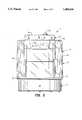
- FIG. 2is a front elevational view of the humidifier
- FIG. 3is a rear elevational view of the humidifier
- FIG. 4is a top view of the humidifier
- FIG. 5is a bottom view of the humidifier
- FIG. 6is a left side elevational view of the humidifier
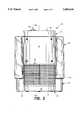
- FIG. 7is a cross-sectional view taken along lines 7--7 in FIG. 2;
- FIG. 8is a perspective view of a water tank used in the humidifier shown in FIGS. 1-7.
- a humidifier 11includes a base 12, and a humidification unit 13 having an upright housing portion 16 and a removable water tank 14 both mounted on the base 12.
- the base 12is generally key-shaped from top view including a circular portion 18 and a rectangular portion 19 as shown in FIG. 1.
- a peripheral wall 23extends upwardly from a circular bottom surface 22 of the base 12, and an upright housing portion 21 projects upwardly from a bottom surface 24 of the rectangular portion 19.
- Extending upwardly from the peripheral wall 21 of the base 12is a horizontal top surface 25 of the upright housing portion 19.
- An inner vertical wall 28projects downwardly from the horizontal top surface 25 to meet an outer upper edge 29 of the rectangular portion 19.
- the tank 14includes an inverted cup-shaped housing 31 and a lid portion 32 permanently sealed in an open bottom end thereof and forming a bottom wall.
- a substantially planar top wall 33 of the tank 14is joined to the bottom wall 32 by vertical side wall portions 34 of the housing 31.
- the horizontally positioned lid portion 32is supported on a top edge 35 of the peripheral wall 23 of the base portion 12. Extending through an outer peripheral wall 36 of the housing portion 16 are air intake openings 38 while exhaust openings 39 project through a horizontal top surface 40 thereof.
- a blower assembly 41is mounted below the horizontal top surface 40 and within the housing 16. Included is the blower assembly 41 is a motor 42, a horizontally oriented cylindrical blower wheel 43 mounted on a motor shaft 44, and a blower housing 45. Defined by the blower housing 45 are an air intake opening 46 and an exhaust opening 47 aligned with and adjacent to the exhaust openings 39 of the upright housing 16. When a control switch 51 mounted on the horizontal top surface 25 is closed, the motor 42 is energized to produce rotation of the shaft 44.
- Resultant spinning of the blower wheel 43draws air into the housing 16 through the intake openings 38, through the interior of the housing 16, through the intake opening 46 of the blower housing 45, and then out of the humidifier 11 through the air exhaust opening 47 of the blower housing 45 and the exhaust openings 39 in the horizontal top surface 40.
- a tubular projection 51with a hollow interior defining female threads 53 (FIG. 7).
- the tubular projection 51together with an adjacent opening 52 (FIG. 1) through the lid 32 constitute a water fill opening and discharge opening for the tank 14.
- a cap/valve assembly 55is engaged within the threads 53 of the tubular projection 51.
- the cap/valve assembly 55consists of a cylindrical cap 56, a valve plunger 57, a rubber valve seal 58, and a compression spring 59.
- Formed on the cylindrical cap 56are an outer male threaded cylindrical wall 61, a horizontal circular bottom wall 62 and an axial discharge opening 63.
- valve plunger 57is loosely positioned through the opening 63 to allow axial movement of the plunger 57 relative the cap 56. Attached to the top end of the valve plunger 57 is the valve seal 58 and the spring 59 is compressed between the cap 56 and a lower end of the plunger 57 to bias the rubber valve seal 58 towards the axial discharge opening 63.
- a tray 65defining a reservoir 66.
- the tray 65has a "tee" shaped horizontal bottom surface 68 with a peripheral wall 69 extending upwardly therefrom. Also extending upwardly from the horizontal bottom surface 68 of the tray 65 is a cylindrical valve actuator post 71 positioned directly below and concentric with the cap/valve assembly 55 of the tank 14.
- an evaporative wick pad 73which extends upwardly into the upright housing portion 16 and within an airstream path therethrough.
- the tank 14After being filled with water and attached to the cap/valve assembly 55, the tank 14 is positioned on the peripheral wall 23 of the base 12. With the tank 14 in that position, the valve actuator 59 in the reservoir 66 pushes the valve plunger 57 upwardly to remove the rubber valve seal 58 away from the axial discharge opening 63 of the cap 56. Water then flows from the tank 14 through the axial discharge opening 63 into the reservoir 66. As water escapes from the tank 14, air simultaneously enters the tank through the axial opening 63. The water level rises until reaching the level of the horizontal bottom wall 62 of the cap 56. At that time water seals the air path into the tank 14 and preventing further discharge of water from the tank 14.
- Water in the reservoir 66is absorbed by a lower portion 81 of the wicking pad 73 and drawn by capillary action upward into an upper portion 82 thereof.
- the water in the upper portion 82is subjected to the airstream through the upright housing 16 which airflow accelerates the evaporation of moisture and causes the humidification desired of the humidifier 11.
- the water levelattempts to fall, but thereby exposes the horizontal bottom wall 62 of the cap 56 to allow air to enter the tank 14 and water to thereby escape therefrom. In this manner, the water in the reservoir 66 is maintained at its normal operating level until such time as the tank's water supply has been depleted.
- a lower handle 85projecting downwardly therefrom.
- An outer extremity 86 of the lower handle 85is aligned substantially with an outer extremity 87 of the downwardly projecting cap/valve assembly 55.
- the lower handle 85facilitates transport of the tank 14 with the assembly facing upwardly to thereby prevent inadvertent spillage of water through the discharge opening 63.
- the planar top wall 33 of the housing 31accommodates support of the tank 14 on a suitable support surface.
- the lower handle 85can function as a support for the tank 14 when removed from the base 12 and positioned on a flat surface. The support provided by the lower handle reduces the possibility of damage to the valve assembly 55 of undesirable tipping over of the tank 12.
- the lower handle 85can be alternatively used in conjunction with an upper handle 91 projecting upwardly from a recessed surface 92 in the top wall 33 of the tank 14.
- the two handles 85, 91permit the use of two hands to more readily accommodate transport of the tank 14 when filled and relatively heavy.
Landscapes
- Engineering & Computer Science (AREA)
- Chemical & Material Sciences (AREA)
- Combustion & Propulsion (AREA)
- Mechanical Engineering (AREA)
- General Engineering & Computer Science (AREA)
- Air Humidification (AREA)
- Details Of Rigid Or Semi-Rigid Containers (AREA)
Abstract
Description
Claims (16)
Priority Applications (4)
| Application Number | Priority Date | Filing Date | Title |
|---|---|---|---|
| US08/360,473US5483616A (en) | 1994-12-21 | 1994-12-21 | Humidifier tank with improved handle |
| CA002151998ACA2151998C (en) | 1994-12-21 | 1995-06-16 | Humidifier tank with improved handle |
| EP95308974AEP0718565A3 (en) | 1994-12-21 | 1995-12-11 | Humidifier tank with improved handle |
| JP7349798AJPH08233314A (en) | 1994-12-21 | 1995-12-21 | Humidifier tank with improved type handle |
Applications Claiming Priority (1)
| Application Number | Priority Date | Filing Date | Title |
|---|---|---|---|
| US08/360,473US5483616A (en) | 1994-12-21 | 1994-12-21 | Humidifier tank with improved handle |
Publications (1)
| Publication Number | Publication Date |
|---|---|
| US5483616Atrue US5483616A (en) | 1996-01-09 |
Family
ID=23418105
Family Applications (1)
| Application Number | Title | Priority Date | Filing Date |
|---|---|---|---|
| US08/360,473Expired - Fee RelatedUS5483616A (en) | 1994-12-21 | 1994-12-21 | Humidifier tank with improved handle |
Country Status (4)
| Country | Link |
|---|---|
| US (1) | US5483616A (en) |
| EP (1) | EP0718565A3 (en) |
| JP (1) | JPH08233314A (en) |
| CA (1) | CA2151998C (en) |
Cited By (82)
| Publication number | Priority date | Publication date | Assignee | Title |
|---|---|---|---|---|
| USD395491S (en) | 1996-01-16 | 1998-06-23 | Honeywell Consumer Products, Inc. | Humidifier with outlet grill and medicine cup |
| US5783117A (en)* | 1997-01-09 | 1998-07-21 | Hunter Fan Company | Evaporative humidifier |
| US6052511A (en)* | 1998-12-18 | 2000-04-18 | Honeywell Inc. | Humidifier with removable water supply tank |
| US6149141A (en)* | 1998-12-18 | 2000-11-21 | Honeywell Inc. | Portable evaporative humidifier apparatus |
| US6259860B1 (en)* | 2000-10-30 | 2001-07-10 | Huang Chen-Lung | Humidifier |
| US6275652B1 (en)* | 1999-08-09 | 2001-08-14 | The Holmes Group, Inc. | Heating element for a humidifier |
| USD449676S1 (en) | 2000-08-11 | 2001-10-23 | Hamilton Beach/Proctor-Silex, Inc. | Humidifier |
| WO2002013957A1 (en)* | 2000-08-11 | 2002-02-21 | Hamilton Beach/Proctor-Silex, Inc. | Evaporative humidifier |
| US6398196B1 (en) | 2000-03-20 | 2002-06-04 | Allied Systems Research, Inc. | Steam humidifier for furnaces |
| US6622993B2 (en) | 2000-10-30 | 2003-09-23 | Hamilton Beach/Proctor-Silex, Inc. | Humidifier including output efficiency and liquid level indicators |
| USD484962S1 (en) | 2002-10-18 | 2004-01-06 | Kaz, Inc. | Humidifier |
| USD487503S1 (en) | 2003-04-18 | 2004-03-09 | Royal-G Enterprise Co., Ltd. | Humidifier |
| US6832753B1 (en)* | 2003-08-28 | 2004-12-21 | Royal-G Enterprise Co., Ltd. | Humidifier with a water wheel device |
| US20050121540A1 (en)* | 2002-03-01 | 2005-06-09 | Kenji Torigoe | Mist generating device |
| US20050151280A1 (en)* | 2004-01-09 | 2005-07-14 | Jon French | Humidifier |
| USD513797S1 (en) | 2004-07-09 | 2006-01-24 | Burton, Inc. | Humidifier |
| USD548318S1 (en)* | 2005-11-08 | 2007-08-07 | Reckitt Benckiser (Uk) Limited | Air freshener device |
| USD551334S1 (en)* | 2006-08-29 | 2007-09-18 | Reckitt Benekiser (Uk) Limited | Air freshener device |
| USD556311S1 (en)* | 2006-05-05 | 2007-11-27 | Reckitt Benckiser (Uk) Limited | Air freshener device |
| US20080072900A1 (en)* | 2003-06-20 | 2008-03-27 | Resmed Limited | Breathable Gas Apparatus With Humidifier |
| USD596730S1 (en)* | 2007-11-05 | 2009-07-21 | Reckitt Benckiser (Uk) Limited | Air freshener device |
| USD596729S1 (en)* | 2007-11-05 | 2009-07-21 | Recknitt Benckiser (UK) Limited | Air freshener |
| US20090277971A1 (en)* | 2008-05-12 | 2009-11-12 | James Scott | Economical, dripless, reciprocating atomizer |
| US20110017212A1 (en)* | 2003-06-20 | 2011-01-27 | Resmed Limited | Breathable gas apparatus with humidifier |
| CN103306950A (en)* | 2012-03-06 | 2013-09-18 | 戴森技术有限公司 | humidifier |
| CN103306948A (en)* | 2012-03-06 | 2013-09-18 | 戴森技术有限公司 | Humidifying apparatus |
| US8783663B2 (en) | 2009-03-04 | 2014-07-22 | Dyson Technology Limited | Humidifying apparatus |
| US8789525B2 (en) | 2007-06-07 | 2014-07-29 | Resmed Limited | Tub for humidifier |
| USD728092S1 (en) | 2013-08-01 | 2015-04-28 | Dyson Technology Limited | Fan |
| USD728769S1 (en) | 2013-08-01 | 2015-05-05 | Dyson Technology Limited | Fan |
| USD728770S1 (en) | 2013-08-01 | 2015-05-05 | Dyson Technology Limited | Fan |
| USD729373S1 (en) | 2013-03-07 | 2015-05-12 | Dyson Technology Limited | Fan |
| USD729374S1 (en) | 2013-03-07 | 2015-05-12 | Dyson Technology Limited | Fan |
| USD729372S1 (en) | 2013-03-07 | 2015-05-12 | Dyson Technology Limited | Fan |
| USD729376S1 (en) | 2013-03-07 | 2015-05-12 | Dyson Technology Limited | Fan |
| USD729375S1 (en) | 2013-03-07 | 2015-05-12 | Dyson Technology Limited | Fan |
| USD729925S1 (en) | 2013-03-07 | 2015-05-19 | Dyson Technology Limited | Fan |
| US9127855B2 (en) | 2011-07-27 | 2015-09-08 | Dyson Technology Limited | Fan assembly |
| USD746425S1 (en) | 2013-01-18 | 2015-12-29 | Dyson Technology Limited | Humidifier |
| USD746966S1 (en) | 2013-01-18 | 2016-01-05 | Dyson Technology Limited | Humidifier |
| USD747450S1 (en) | 2013-01-18 | 2016-01-12 | Dyson Technology Limited | Humidifier |
| USD749231S1 (en) | 2013-01-18 | 2016-02-09 | Dyson Technology Limited | Humidifier |
| US9272116B2 (en) | 1999-08-05 | 2016-03-01 | Resmed R&D Germany Gmbh | Apparatus for humidifying a respiratory gas |
| US9316405B2 (en)* | 2014-07-10 | 2016-04-19 | Dana Electronics Co., Ltd. | Cyclone type humidifier and wet air purifier combination device using centrifugal force |
| KR20160057471A (en)* | 2013-11-11 | 2016-05-23 | 웬 칭 리 | Water dispenser and cup thereof |
| US9366449B2 (en) | 2012-03-06 | 2016-06-14 | Dyson Technology Limited | Humidifying apparatus |
| US9410711B2 (en) | 2013-09-26 | 2016-08-09 | Dyson Technology Limited | Fan assembly |
| US9458853B2 (en) | 2011-07-27 | 2016-10-04 | Dyson Technology Limited | Fan assembly |
| US9599356B2 (en) | 2014-07-29 | 2017-03-21 | Dyson Technology Limited | Humidifying apparatus |
| USD787036S1 (en)* | 2015-02-13 | 2017-05-16 | Samsung Electronics Co., Ltd. | Bucket for dehumidifier |
| USD791925S1 (en)* | 2015-07-13 | 2017-07-11 | Samsung Electronics Co., Ltd | Water box for dehumidifier |
| US9745981B2 (en) | 2011-11-11 | 2017-08-29 | Dyson Technology Limited | Fan assembly |
| US9797613B2 (en) | 2012-03-06 | 2017-10-24 | Dyson Technology Limited | Humidifying apparatus |
| US9797612B2 (en) | 2013-01-29 | 2017-10-24 | Dyson Technology Limited | Fan assembly |
| US9903602B2 (en) | 2014-07-29 | 2018-02-27 | Dyson Technology Limited | Humidifying apparatus |
| US9927136B2 (en) | 2012-03-06 | 2018-03-27 | Dyson Technology Limited | Fan assembly |
| US9982677B2 (en) | 2014-07-29 | 2018-05-29 | Dyson Technology Limited | Fan assembly |
| US20190083671A1 (en)* | 2017-09-20 | 2019-03-21 | Great Innovations, LLC | Humidifier with aromatherapy tray |
| US10408478B2 (en) | 2012-03-06 | 2019-09-10 | Dyson Technology Limited | Humidifying apparatus |
| US10465928B2 (en) | 2012-03-06 | 2019-11-05 | Dyson Technology Limited | Humidifying apparatus |
| US10612565B2 (en) | 2013-01-29 | 2020-04-07 | Dyson Technology Limited | Fan assembly |
| US10709866B2 (en) | 2014-05-13 | 2020-07-14 | Fisher & Paykel Healthcare Limited | Usability features for respiratory humidification system |
| USD899598S1 (en) | 2018-09-04 | 2020-10-20 | 3B Medical, Inc. | CPAP device |
| US10828482B2 (en) | 2013-12-20 | 2020-11-10 | Fisher & Paykel Healthcare Limited | Humidification system connections |
| US10962244B2 (en)* | 2018-03-22 | 2021-03-30 | Foshan Jinxinghui Electrical Appliance Co., Ltd. | Humidifier |
| US10962245B2 (en)* | 2017-07-24 | 2021-03-30 | Foshan Jinxinghui Electrical Appliance Co., Ltd. | Humidifier to which water is supplied from the top |
| US10974015B2 (en) | 2012-03-15 | 2021-04-13 | Fisher & Paykel Healthcare Limited | Respiratory gas humidification system |
| US11129956B2 (en) | 2012-04-27 | 2021-09-28 | Fisher & Paykel Healthcare Limited | Usability features for respiratory humidification system |
| WO2021216472A1 (en)* | 2020-04-20 | 2021-10-28 | Vornado Air, Llc | Portable humidifier |
| US11173272B2 (en) | 2014-05-02 | 2021-11-16 | Fisher & Paykel Healthcare Limited | Gas humidification arrangement |
| US11278689B2 (en) | 2014-11-17 | 2022-03-22 | Fisher & Paykel Healthcare Limited | Humidification of respiratory gases |
| US11306929B2 (en) | 2018-09-09 | 2022-04-19 | Vornado Air, Llc | Portable steam humidifier |
| US11324911B2 (en) | 2014-06-03 | 2022-05-10 | Fisher & Paykel Healthcare Limited | Flow mixers for respiratory therapy systems |
| US11351332B2 (en) | 2016-12-07 | 2022-06-07 | Fisher & Paykel Healthcare Limited | Sensing arrangements for medical devices |
| US11511069B2 (en) | 2013-09-13 | 2022-11-29 | Fisher & Paykel Healthcare Limited | Humidification system |
| US11549699B2 (en)* | 2017-10-03 | 2023-01-10 | Vornado Air, Llc | Portable humidifier |
| US11559653B2 (en) | 2014-02-07 | 2023-01-24 | Fisher & Paykel Healthcare Limited | Respiratory humidification system |
| US20230136098A1 (en)* | 2021-11-02 | 2023-05-04 | Shenzhen Miaoxin Technology Co., Ltd | Humidifier |
| US20230241343A1 (en)* | 2020-09-08 | 2023-08-03 | ResMed Pty Ltd | Humidification platform for use with a portable cpap device |
| US11801360B2 (en) | 2013-09-13 | 2023-10-31 | Fisher & Paykel Healthcare Limited | Connections for humidification system |
| USD1024298S1 (en)* | 2021-11-24 | 2024-04-23 | Chuang DU | Humidifier tank |
| USD1024299S1 (en)* | 2021-11-24 | 2024-04-23 | Chuang DU | Humidifier tank |
Families Citing this family (12)
| Publication number | Priority date | Publication date | Assignee | Title |
|---|---|---|---|---|
| JP4660031B2 (en)* | 2001-08-09 | 2011-03-30 | 三洋電機株式会社 | Humidifier |
| JP2003074916A (en)* | 2001-08-29 | 2003-03-12 | Sanyo Electric Co Ltd | Humidifier |
| CN100362284C (en)* | 2004-12-08 | 2008-01-16 | 黄仲盘 | Safety structure for humidifier |
| JP4809125B2 (en)* | 2006-05-19 | 2011-11-09 | ダイニチ工業株式会社 | Liquid supply device, humidifier equipped with liquid supply device, and heater equipped with liquid supply device |
| JP2008039326A (en)* | 2006-08-09 | 2008-02-21 | Sharp Corp | Humidifier |
| JP4545773B2 (en)* | 2007-03-30 | 2010-09-15 | パナソニックエコシステムズ株式会社 | Vaporizing humidifier |
| JP2009036407A (en)* | 2007-07-31 | 2009-02-19 | Sanyo Electric Co Ltd | Humidifier |
| JP2013050290A (en)* | 2011-08-01 | 2013-03-14 | Panasonic Corp | Humidifier and hot air humidifier including the same |
| CN102818343B (en)* | 2012-07-17 | 2014-07-30 | 格力电器(中山)小家电制造有限公司 | Airflow switching device and method |
| WO2020243959A1 (en)* | 2019-06-06 | 2020-12-10 | Vincent Medical (Dong Guan) Manufacturing Co., Ltd. | An improved liquid reservoir for a humidifier, a medical device containing, a humidifier containing, and a method therefor |
| JP7190399B2 (en)* | 2019-06-28 | 2022-12-15 | ダイニチ工業株式会社 | humidifier |
| JP2021006752A (en)* | 2019-06-28 | 2021-01-21 | ダイニチ工業株式会社 | Water tank and humidifier |
Citations (4)
| Publication number | Priority date | Publication date | Assignee | Title |
|---|---|---|---|---|
| US2369623A (en)* | 1943-03-01 | 1945-02-13 | Ray C Utley | Hat steamer |
| US2639365A (en)* | 1951-06-08 | 1953-05-19 | Krampe | Portable steam cleaner |
| US4752423A (en)* | 1986-09-18 | 1988-06-21 | Wellman Industrial Company, Ltd. | Combined humidifier and fan heater unit |
| US5247604A (en)* | 1992-04-20 | 1993-09-21 | Duracraft Corporation | Humidifier tank with leakage control cap |
Family Cites Families (1)
| Publication number | Priority date | Publication date | Assignee | Title |
|---|---|---|---|---|
| DE3516829A1 (en)* | 1985-05-10 | 1986-11-13 | Andrade, Samuel Rebelo de, 6835 Brühl | Air humidifier according to the evaporation principle |
- 1994
- 1994-12-21USUS08/360,473patent/US5483616A/ennot_activeExpired - Fee Related
- 1995
- 1995-06-16CACA002151998Apatent/CA2151998C/ennot_activeExpired - Fee Related
- 1995-12-11EPEP95308974Apatent/EP0718565A3/ennot_activeWithdrawn
- 1995-12-21JPJP7349798Apatent/JPH08233314A/enactivePending
Patent Citations (4)
| Publication number | Priority date | Publication date | Assignee | Title |
|---|---|---|---|---|
| US2369623A (en)* | 1943-03-01 | 1945-02-13 | Ray C Utley | Hat steamer |
| US2639365A (en)* | 1951-06-08 | 1953-05-19 | Krampe | Portable steam cleaner |
| US4752423A (en)* | 1986-09-18 | 1988-06-21 | Wellman Industrial Company, Ltd. | Combined humidifier and fan heater unit |
| US5247604A (en)* | 1992-04-20 | 1993-09-21 | Duracraft Corporation | Humidifier tank with leakage control cap |
Cited By (143)
| Publication number | Priority date | Publication date | Assignee | Title |
|---|---|---|---|---|
| USD395491S (en) | 1996-01-16 | 1998-06-23 | Honeywell Consumer Products, Inc. | Humidifier with outlet grill and medicine cup |
| US5783117A (en)* | 1997-01-09 | 1998-07-21 | Hunter Fan Company | Evaporative humidifier |
| US6052511A (en)* | 1998-12-18 | 2000-04-18 | Honeywell Inc. | Humidifier with removable water supply tank |
| US6149141A (en)* | 1998-12-18 | 2000-11-21 | Honeywell Inc. | Portable evaporative humidifier apparatus |
| US9302067B2 (en) | 1999-08-05 | 2016-04-05 | Resmed R&D Germany Gmbh | Apparatus for humidifying a respiratory gas |
| US10052450B2 (en) | 1999-08-05 | 2018-08-21 | Resmed R&D Germany Gmbh | Apparatus for humidifying a respiratory gas |
| US9884163B2 (en) | 1999-08-05 | 2018-02-06 | RedMed R&D Germany GmbH | Apparatus for humidifying a respiratory gas |
| US9555211B2 (en) | 1999-08-05 | 2017-01-31 | Resmed R&D Germany Gmbh | Apparatus for humidifying a respiratory gas |
| US9545493B2 (en) | 1999-08-05 | 2017-01-17 | Resmed R&D Germany Gmbh | Apparatus for humidifying a respiratory gas |
| US9545494B2 (en) | 1999-08-05 | 2017-01-17 | Resmed R&D Germany Gmbh | Apparatus for humidifying a respiratory gas |
| US9272116B2 (en) | 1999-08-05 | 2016-03-01 | Resmed R&D Germany Gmbh | Apparatus for humidifying a respiratory gas |
| US6275652B1 (en)* | 1999-08-09 | 2001-08-14 | The Holmes Group, Inc. | Heating element for a humidifier |
| US6398196B1 (en) | 2000-03-20 | 2002-06-04 | Allied Systems Research, Inc. | Steam humidifier for furnaces |
| USD449676S1 (en) | 2000-08-11 | 2001-10-23 | Hamilton Beach/Proctor-Silex, Inc. | Humidifier |
| GB2383277A (en)* | 2000-08-11 | 2003-06-25 | Hamilton Beach Proctor Silex | Evaporative humidifier |
| WO2002013957A1 (en)* | 2000-08-11 | 2002-02-21 | Hamilton Beach/Proctor-Silex, Inc. | Evaporative humidifier |
| US6715739B2 (en) | 2000-08-11 | 2004-04-06 | Hamilton Beach/Proctor-Silex, Inc. | Evaporative humidifier |
| GB2383277B (en)* | 2000-08-11 | 2004-06-23 | Hamilton Beach Proctor Silex | Evaporative humidifier |
| US6427984B1 (en) | 2000-08-11 | 2002-08-06 | Hamilton Beach/Proctor-Silex, Inc. | Evaporative humidifier |
| US20040012103A1 (en)* | 2000-08-11 | 2004-01-22 | Hamilton Beach/Proctor-Silex, Inc. | Evaporative humidifier |
| US6604733B2 (en) | 2000-08-11 | 2003-08-12 | Hamilton Beach/Proctor-Silex, Inc. | Evaporative humidifier |
| US6622993B2 (en) | 2000-10-30 | 2003-09-23 | Hamilton Beach/Proctor-Silex, Inc. | Humidifier including output efficiency and liquid level indicators |
| US6259860B1 (en)* | 2000-10-30 | 2001-07-10 | Huang Chen-Lung | Humidifier |
| US7055763B2 (en)* | 2002-03-01 | 2006-06-06 | Sera Corporation Inc. | Mist generating device |
| US20050121540A1 (en)* | 2002-03-01 | 2005-06-09 | Kenji Torigoe | Mist generating device |
| USD484962S1 (en) | 2002-10-18 | 2004-01-06 | Kaz, Inc. | Humidifier |
| USD487503S1 (en) | 2003-04-18 | 2004-03-09 | Royal-G Enterprise Co., Ltd. | Humidifier |
| US10850053B2 (en) | 2003-06-20 | 2020-12-01 | ResMed Pty Ltd | Breathable gas supply apparatus |
| US9610420B2 (en) | 2003-06-20 | 2017-04-04 | Resmed Limited | Breathable gas apparatus with humidifier |
| US9358359B2 (en) | 2003-06-20 | 2016-06-07 | Resmed Limited | Breathable gas apparatus with humidifier |
| US9539409B2 (en) | 2003-06-20 | 2017-01-10 | Resmed Limited | Breathable gas apparatus with humidifier |
| US9227035B2 (en) | 2003-06-20 | 2016-01-05 | Resmed Limited | Breathable gas apparatus with humidifier |
| US9072860B2 (en) | 2003-06-20 | 2015-07-07 | Resmed Limited | Breathable gas apparatus with humidifier |
| US20100192094A1 (en)* | 2003-06-20 | 2010-07-29 | Resmed Limited | Flow generator with patient reminder |
| US20110017212A1 (en)* | 2003-06-20 | 2011-01-27 | Resmed Limited | Breathable gas apparatus with humidifier |
| US20110023877A1 (en)* | 2003-06-20 | 2011-02-03 | Resmed Limited | Breathable gas apparatus with humidifier |
| US20110180068A1 (en)* | 2003-06-20 | 2011-07-28 | Resmed Limited | Breathable gas apparatus with humidifier |
| US8006691B2 (en)* | 2003-06-20 | 2011-08-30 | Resmed Limited | Humidifier with removable water tank |
| US8020551B2 (en)* | 2003-06-20 | 2011-09-20 | Resmed Limited | Breathable gas apparatus with humidifier |
| US8028693B2 (en)* | 2003-06-20 | 2011-10-04 | Resmed Limited | Breathable gas apparatus with humidifier |
| US8042535B2 (en) | 2003-06-20 | 2011-10-25 | Resmed Limited | Breathable gas apparatus with humidifier |
| US9038631B2 (en) | 2003-06-20 | 2015-05-26 | Resmed Limited | Breathable gas apparatus with humidifier |
| US11413412B2 (en) | 2003-06-20 | 2022-08-16 | ResMed Pty Ltd | Breathable gas supply apparatus |
| US11260187B2 (en) | 2003-06-20 | 2022-03-01 | ResMed Pty Ltd | Breathable gas supply apparatus |
| US11235115B2 (en) | 2003-06-20 | 2022-02-01 | ResMed Pty Ltd | Breathable gas apparatus with humidifier |
| US9038632B2 (en) | 2003-06-20 | 2015-05-26 | Resmed Limited | Breathable gas apparatus with humidifier |
| US20080072900A1 (en)* | 2003-06-20 | 2008-03-27 | Resmed Limited | Breathable Gas Apparatus With Humidifier |
| US10881820B2 (en) | 2003-06-20 | 2021-01-05 | ResMed Pty Ltd | Breathable gas apparatus with humidifier |
| USRE46543E1 (en) | 2003-06-20 | 2017-09-12 | Resmed Limited | Breathable gas apparatus with humidifier |
| US10201676B2 (en) | 2003-06-20 | 2019-02-12 | Resmed Limited | Breathable gas supply apparatus |
| US10293125B2 (en) | 2003-06-20 | 2019-05-21 | Resmed Limited | Flow generator with patient reminder |
| US6832753B1 (en)* | 2003-08-28 | 2004-12-21 | Royal-G Enterprise Co., Ltd. | Humidifier with a water wheel device |
| US7073782B2 (en) | 2004-01-09 | 2006-07-11 | Jcs/Thg, Llc | Humidifier |
| US20050151280A1 (en)* | 2004-01-09 | 2005-07-14 | Jon French | Humidifier |
| US7377494B2 (en) | 2004-01-09 | 2008-05-27 | Sunbeam Products, Inc. | Humidifier |
| US20060170121A1 (en)* | 2004-01-09 | 2006-08-03 | Jcs/Thg, Llc. | Humidifier |
| USD513797S1 (en) | 2004-07-09 | 2006-01-24 | Burton, Inc. | Humidifier |
| USD548318S1 (en)* | 2005-11-08 | 2007-08-07 | Reckitt Benckiser (Uk) Limited | Air freshener device |
| USD556311S1 (en)* | 2006-05-05 | 2007-11-27 | Reckitt Benckiser (Uk) Limited | Air freshener device |
| USD551334S1 (en)* | 2006-08-29 | 2007-09-18 | Reckitt Benekiser (Uk) Limited | Air freshener device |
| US8789525B2 (en) | 2007-06-07 | 2014-07-29 | Resmed Limited | Tub for humidifier |
| US12011545B2 (en) | 2007-06-07 | 2024-06-18 | ResMed Pty Ltd | Tub for humidifier |
| US10478585B2 (en) | 2007-06-07 | 2019-11-19 | ResMed Pty Ltd | Tub for humidifier |
| USD596729S1 (en)* | 2007-11-05 | 2009-07-21 | Recknitt Benckiser (UK) Limited | Air freshener |
| USD596730S1 (en)* | 2007-11-05 | 2009-07-21 | Reckitt Benckiser (Uk) Limited | Air freshener device |
| US20090277971A1 (en)* | 2008-05-12 | 2009-11-12 | James Scott | Economical, dripless, reciprocating atomizer |
| US8783663B2 (en) | 2009-03-04 | 2014-07-22 | Dyson Technology Limited | Humidifying apparatus |
| US9335064B2 (en) | 2011-07-27 | 2016-05-10 | Dyson Technology Limited | Fan assembly |
| US9458853B2 (en) | 2011-07-27 | 2016-10-04 | Dyson Technology Limited | Fan assembly |
| US9291361B2 (en) | 2011-07-27 | 2016-03-22 | Dyson Technology Limited | Fan assembly |
| US10094581B2 (en) | 2011-07-27 | 2018-10-09 | Dyson Technology Limited | Fan assembly |
| US9127855B2 (en) | 2011-07-27 | 2015-09-08 | Dyson Technology Limited | Fan assembly |
| US9745981B2 (en) | 2011-11-11 | 2017-08-29 | Dyson Technology Limited | Fan assembly |
| US10563875B2 (en)* | 2012-03-06 | 2020-02-18 | Dyson Technology Limited | Humidifying apparatus |
| US9927136B2 (en) | 2012-03-06 | 2018-03-27 | Dyson Technology Limited | Fan assembly |
| US10408478B2 (en) | 2012-03-06 | 2019-09-10 | Dyson Technology Limited | Humidifying apparatus |
| US9366449B2 (en) | 2012-03-06 | 2016-06-14 | Dyson Technology Limited | Humidifying apparatus |
| US10465928B2 (en) | 2012-03-06 | 2019-11-05 | Dyson Technology Limited | Humidifying apparatus |
| US9797613B2 (en) | 2012-03-06 | 2017-10-24 | Dyson Technology Limited | Humidifying apparatus |
| CN103306950A (en)* | 2012-03-06 | 2013-09-18 | 戴森技术有限公司 | humidifier |
| US9752789B2 (en)* | 2012-03-06 | 2017-09-05 | Dyson Technology Limited | Humidifying apparatus |
| US20130249124A1 (en)* | 2012-03-06 | 2013-09-26 | Dyson Technology Limited | Humidifying apparatus |
| CN103306948B (en)* | 2012-03-06 | 2016-06-29 | 戴森技术有限公司 | Damping device |
| CN103306948A (en)* | 2012-03-06 | 2013-09-18 | 戴森技术有限公司 | Humidifying apparatus |
| EP2636962A3 (en)* | 2012-03-06 | 2013-12-11 | Dyson Technology Limited | Humidifying apparatus |
| US10974015B2 (en) | 2012-03-15 | 2021-04-13 | Fisher & Paykel Healthcare Limited | Respiratory gas humidification system |
| US12350436B2 (en) | 2012-03-15 | 2025-07-08 | Fisher & Paykel Healthcare Limited | Respiratory gas humidification system |
| US11129956B2 (en) | 2012-04-27 | 2021-09-28 | Fisher & Paykel Healthcare Limited | Usability features for respiratory humidification system |
| US11878093B2 (en) | 2012-04-27 | 2024-01-23 | Fisher & Paykel Healthcare Limited | Usability features for respiratory humidification system |
| USD749231S1 (en) | 2013-01-18 | 2016-02-09 | Dyson Technology Limited | Humidifier |
| USD746425S1 (en) | 2013-01-18 | 2015-12-29 | Dyson Technology Limited | Humidifier |
| USD746966S1 (en) | 2013-01-18 | 2016-01-05 | Dyson Technology Limited | Humidifier |
| USD747450S1 (en) | 2013-01-18 | 2016-01-12 | Dyson Technology Limited | Humidifier |
| US10612565B2 (en) | 2013-01-29 | 2020-04-07 | Dyson Technology Limited | Fan assembly |
| US9797612B2 (en) | 2013-01-29 | 2017-10-24 | Dyson Technology Limited | Fan assembly |
| USD729376S1 (en) | 2013-03-07 | 2015-05-12 | Dyson Technology Limited | Fan |
| USD729925S1 (en) | 2013-03-07 | 2015-05-19 | Dyson Technology Limited | Fan |
| USD729372S1 (en) | 2013-03-07 | 2015-05-12 | Dyson Technology Limited | Fan |
| USD729375S1 (en) | 2013-03-07 | 2015-05-12 | Dyson Technology Limited | Fan |
| USD729374S1 (en) | 2013-03-07 | 2015-05-12 | Dyson Technology Limited | Fan |
| USD729373S1 (en) | 2013-03-07 | 2015-05-12 | Dyson Technology Limited | Fan |
| USD728769S1 (en) | 2013-08-01 | 2015-05-05 | Dyson Technology Limited | Fan |
| USD728770S1 (en) | 2013-08-01 | 2015-05-05 | Dyson Technology Limited | Fan |
| USD728092S1 (en) | 2013-08-01 | 2015-04-28 | Dyson Technology Limited | Fan |
| US11801360B2 (en) | 2013-09-13 | 2023-10-31 | Fisher & Paykel Healthcare Limited | Connections for humidification system |
| US12053589B2 (en) | 2013-09-13 | 2024-08-06 | Fisher & Paykel Healthcare Limited | Humidification system |
| US11511069B2 (en) | 2013-09-13 | 2022-11-29 | Fisher & Paykel Healthcare Limited | Humidification system |
| US9410711B2 (en) | 2013-09-26 | 2016-08-09 | Dyson Technology Limited | Fan assembly |
| US10005658B2 (en)* | 2013-11-11 | 2018-06-26 | Wen-Ching Lee | Water dispenser and detachable water container with lateral connector connected thereto |
| US20160176698A1 (en)* | 2013-11-11 | 2016-06-23 | Wen-Ching Lee | Water dispenser and water container thereof |
| KR20160057471A (en)* | 2013-11-11 | 2016-05-23 | 웬 칭 리 | Water dispenser and cup thereof |
| CN106659313A (en)* | 2013-11-11 | 2017-05-10 | 李文钦 | Water dispenser and water cup thereof |
| US10828482B2 (en) | 2013-12-20 | 2020-11-10 | Fisher & Paykel Healthcare Limited | Humidification system connections |
| US11826538B2 (en) | 2013-12-20 | 2023-11-28 | Fisher & Paykel Healthcare Limited | Humidification system connections |
| US11559653B2 (en) | 2014-02-07 | 2023-01-24 | Fisher & Paykel Healthcare Limited | Respiratory humidification system |
| US12397127B2 (en) | 2014-02-07 | 2025-08-26 | Fisher & Paykel Healthcare Limited | Respiratory humidification system |
| US11173272B2 (en) | 2014-05-02 | 2021-11-16 | Fisher & Paykel Healthcare Limited | Gas humidification arrangement |
| US10709866B2 (en) | 2014-05-13 | 2020-07-14 | Fisher & Paykel Healthcare Limited | Usability features for respiratory humidification system |
| US11992622B2 (en) | 2014-05-13 | 2024-05-28 | Fisher & Paykel Healthcare Limited | Usability features for respiratory humidification system |
| US11324911B2 (en) | 2014-06-03 | 2022-05-10 | Fisher & Paykel Healthcare Limited | Flow mixers for respiratory therapy systems |
| US11712536B2 (en) | 2014-06-03 | 2023-08-01 | Fisher & Paykel Healthcare Limited | Flow mixers for respiratory therapy systems |
| US9316405B2 (en)* | 2014-07-10 | 2016-04-19 | Dana Electronics Co., Ltd. | Cyclone type humidifier and wet air purifier combination device using centrifugal force |
| US9903602B2 (en) | 2014-07-29 | 2018-02-27 | Dyson Technology Limited | Humidifying apparatus |
| US9982677B2 (en) | 2014-07-29 | 2018-05-29 | Dyson Technology Limited | Fan assembly |
| US9599356B2 (en) | 2014-07-29 | 2017-03-21 | Dyson Technology Limited | Humidifying apparatus |
| US11278689B2 (en) | 2014-11-17 | 2022-03-22 | Fisher & Paykel Healthcare Limited | Humidification of respiratory gases |
| USD787036S1 (en)* | 2015-02-13 | 2017-05-16 | Samsung Electronics Co., Ltd. | Bucket for dehumidifier |
| USD791925S1 (en)* | 2015-07-13 | 2017-07-11 | Samsung Electronics Co., Ltd | Water box for dehumidifier |
| US11351332B2 (en) | 2016-12-07 | 2022-06-07 | Fisher & Paykel Healthcare Limited | Sensing arrangements for medical devices |
| US10962245B2 (en)* | 2017-07-24 | 2021-03-30 | Foshan Jinxinghui Electrical Appliance Co., Ltd. | Humidifier to which water is supplied from the top |
| US20190083671A1 (en)* | 2017-09-20 | 2019-03-21 | Great Innovations, LLC | Humidifier with aromatherapy tray |
| US11549699B2 (en)* | 2017-10-03 | 2023-01-10 | Vornado Air, Llc | Portable humidifier |
| US10962244B2 (en)* | 2018-03-22 | 2021-03-30 | Foshan Jinxinghui Electrical Appliance Co., Ltd. | Humidifier |
| USD899598S1 (en) | 2018-09-04 | 2020-10-20 | 3B Medical, Inc. | CPAP device |
| US11306929B2 (en) | 2018-09-09 | 2022-04-19 | Vornado Air, Llc | Portable steam humidifier |
| CN115803570A (en)* | 2020-04-20 | 2023-03-14 | 沃尔纳多航空有限公司 | portable humidifier |
| WO2021216472A1 (en)* | 2020-04-20 | 2021-10-28 | Vornado Air, Llc | Portable humidifier |
| US20230241343A1 (en)* | 2020-09-08 | 2023-08-03 | ResMed Pty Ltd | Humidification platform for use with a portable cpap device |
| US12023447B2 (en)* | 2020-09-08 | 2024-07-02 | ResMed Pty Ltd | Humidification platform for use with a portable CPAP device |
| US11852374B2 (en)* | 2021-11-02 | 2023-12-26 | Shenzhen Miaoxin Technology Co., Ltd | Humidifier |
| US20230136098A1 (en)* | 2021-11-02 | 2023-05-04 | Shenzhen Miaoxin Technology Co., Ltd | Humidifier |
| USD1024299S1 (en)* | 2021-11-24 | 2024-04-23 | Chuang DU | Humidifier tank |
| USD1024298S1 (en)* | 2021-11-24 | 2024-04-23 | Chuang DU | Humidifier tank |
Also Published As
| Publication number | Publication date |
|---|---|
| JPH08233314A (en) | 1996-09-13 |
| CA2151998A1 (en) | 1996-06-22 |
| EP0718565A3 (en) | 1997-06-18 |
| EP0718565A2 (en) | 1996-06-26 |
| CA2151998C (en) | 2001-12-04 |
Similar Documents
| Publication | Publication Date | Title |
|---|---|---|
| US5483616A (en) | Humidifier tank with improved handle | |
| US6604733B2 (en) | Evaporative humidifier | |
| US5061405A (en) | Constant humidity evaporative wicking filter humidifier | |
| US5547615A (en) | Portable humidifier with bacteriastat dispenser | |
| US6874771B2 (en) | Humidifier with a heating disc | |
| US5162088A (en) | Evaporator apparatus | |
| US5529726A (en) | Evaporative humidifier | |
| JP5130805B2 (en) | Humidifier | |
| US6220579B1 (en) | Warm mist humidifier | |
| CA2305092A1 (en) | Combination humidifier and air purifier | |
| US5143656A (en) | Humidifier with a tamper proof liquid level responsive shut-off | |
| JP2019023539A (en) | Humidifier | |
| JP6960679B2 (en) | humidifier | |
| US5636319A (en) | Portable and personal-sized warm air humidifier | |
| US6176474B1 (en) | Humidifier bottle with side fill/side dispensing cap | |
| JP2020104053A (en) | Liquid refining unit | |
| US20050200031A1 (en) | Humidifier with safety reservoir | |
| JP2003097829A (en) | humidifier | |
| JPH025244Y2 (en) | ||
| JP3119541U (en) | humidifier | |
| JPH0633298Y2 (en) | humidifier | |
| KR0130942Y1 (en) | Humidifier with dehumidifying function | |
| JPS5928262Y2 (en) | humidifier | |
| KR0130943Y1 (en) | Humidifier with dehumidifying function | |
| JP2557203Y2 (en) | Valve mechanism of liquid supply device |
Legal Events
| Date | Code | Title | Description |
|---|---|---|---|
| AS | Assignment | Owner name:DURACRAFT CORPORATION, MASSACHUSETTS Free format text:ASSIGNMENT OF ASSIGNORS INTEREST;ASSIGNORS:CHIU, BERNARD;WANG, JUI-SHANG;GRESENS, STANLEY;REEL/FRAME:007281/0743 Effective date:19941114 | |
| RF | Reissue application filed | Effective date:19980108 | |
| FPAY | Fee payment | Year of fee payment:4 | |
| AS | Assignment | Owner name:KAZ HOME ENVIRONMENT, INC., MASSACHUSETTS Free format text:CHANGE OF NAME;ASSIGNOR:HONEYWELL CONSUMER PRODUCTS, INC.;REEL/FRAME:013897/0758 Effective date:20020827 Owner name:KAZ, INC., NEW YORK Free format text:ASSIGNMENT OF ASSIGNORS INTEREST;ASSIGNOR:KAZ HOME ENVIRONMENT, INC.;REEL/FRAME:013868/0187 Effective date:20030328 | |
| REMI | Maintenance fee reminder mailed | ||
| FPAY | Fee payment | Year of fee payment:8 | |
| SULP | Surcharge for late payment | Year of fee payment:7 | |
| AS | Assignment | Owner name:BANK OF AMERICA, N.A., AS AGENT, MASSACHUSETTS Free format text:SECURITY AGREEMENT;ASSIGNORS:KAZ, INC.;KAZ USA, INC.;KAZ CANADA, INC.;REEL/FRAME:017215/0696 Effective date:20060131 | |
| REMI | Maintenance fee reminder mailed | ||
| LAPS | Lapse for failure to pay maintenance fees | ||
| STCH | Information on status: patent discontinuation | Free format text:PATENT EXPIRED DUE TO NONPAYMENT OF MAINTENANCE FEES UNDER 37 CFR 1.362 | |
| FP | Lapsed due to failure to pay maintenance fee | Effective date:20080109 |