US5482492A - Balloons and balloon valves - Google Patents
Balloons and balloon valvesDownload PDFInfo
- Publication number
- US5482492A US5482492AUS08/179,308US17930894AUS5482492AUS 5482492 AUS5482492 AUS 5482492AUS 17930894 AUS17930894 AUS 17930894AUS 5482492 AUS5482492 AUS 5482492A
- Authority
- US
- United States
- Prior art keywords
- valve
- balloon
- layers
- layer
- inlet end
- Prior art date
- Legal status (The legal status is an assumption and is not a legal conclusion. Google has not performed a legal analysis and makes no representation as to the accuracy of the status listed.)
- Expired - Fee Related
Links
Images


Classifications
- A—HUMAN NECESSITIES
- A63—SPORTS; GAMES; AMUSEMENTS
- A63H—TOYS, e.g. TOPS, DOLLS, HOOPS OR BUILDING BLOCKS
- A63H27/00—Toy aircraft; Other flying toys
- A63H27/10—Balloons
- A—HUMAN NECESSITIES
- A63—SPORTS; GAMES; AMUSEMENTS
- A63H—TOYS, e.g. TOPS, DOLLS, HOOPS OR BUILDING BLOCKS
- A63H27/00—Toy aircraft; Other flying toys
- A63H27/10—Balloons
- A63H2027/1083—Valves or nozzles
Definitions
- the present inventionpertains to balloons, and in particular to valves for use with balloons.
- valve filmsare typically "softer" and are more susceptible to stretching. It has been observed, from time to time, upon insertion of an inflation probe in the balloon valve, that edges of the valve film at the valve inlet may be pushed by the probe into the valve interior.
- the valve films in use today, especially in toy balloons,can be made to stretch if placed under tension, and it is important that edges of the valve film are not allowed to conform to the probe tip, so as to be stretched within the valve passageway by the probe, thus impairing the inflation operation.
- Another object according to principles of the present inventionis to provide an improved valve with so-called “coterminous,” i.e., edges formed by two overlapping layers of valve film which are even with one another.
- a further object according to principles of the present inventionis to provide an improved valve of the above type which may be inexpensively produced by modifying existing valves with minimal cost.
- valve for use in a balloon filled with a pressurized gascomprising:
- first and second layers of flexible valve materialdisposed in at least partially overlapping relationship
- At least one of said first and said second layershaving an inlet end at the inlet end of the tube, which is divided into at least two unconnected parts.
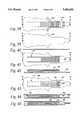
- FIG. 1is a fragmentary top plan view, shown partly cut away, of a balloon and valve assembly illustrating principles according to the present invention.
- FIG. 2is a fragmentary perspective view thereof.
- FIGS. 3-6are fragmentary views thereof with successive layers removed.
- FIG. 7is a cross-sectional view taken along the line 7--7 of FIG. 1, shown at an early stage of probe insertion.
- FIG. 8is a view similar to that of FIG. 7 showing the probe at a later stage of insertion.
- FIG. 9is a top plan view similar to that of FIG. 1 showing the probe inserted.
- FIG. 10is a fragmentary top plan view similar to that of FIG. 5, but shown during probe insertion.
- FIG. 11is a perspective view similar to that of FIG. 2, but showing the probe inserted.
- FIG. 12is a cross-sectional view taken along the line 12--12 of FIG. 2, but shown after inflation.
- FIGS. 13-15are fragmentary top plan views of an alternative embodiment of balloon and valve assemblies illustrating principles of the present invention.
- FIGS. 16-18are top plan views of balloon and valve assemblies showing further alternative embodiments according to principles of the present invention.
- FIG. 19is a fragmentary top plan view, shown partly broken away, of a prior art balloon and valve assembly.
- FIG. 20is a top plan view thereof showing an inflation probe at an early stage of insertion.
- FIG. 21is a fragmentary cross-sectional view taken along the line 21--21 of FIG. 20.
- FIG. 22is a view similar to that of FIG. 21 showing the inflation probe at a later stage of insertion.
- FIG. 23is a fragmentary perspective view, shown partly broken away, of the prior art balloon and valve assembly of FIG. 19.
- FIG. 24is a view similar to that of FIG. 23 showing the inflation probe inserted in the valve.
- FIG. 25is a cross-sectional view taken along the line 25--25 of FIG. 24.
- FIG. 26is a perspective view thereof.
- FIGS. 27-29are fragmentary perspective views of alternative valve assemblies.
- FIG. 30is a fragmentary top plan view of a further embodiment of a balloon assembly according to principles of the present invention.
- FIG. 31is a fragmentary top plan view of the upper layer thereof.
- FIG. 32is a fragmentary cross-sectional view taken along the line 32--32 of FIG. 31.
- FIG. 33is a fragmentary bottom plan view similar to that of FIG. 31 but showing a valve member installed.
- FIG. 34is a fragmentary cross-sectional view taken along the line 34--34 of FIG. 33.
- FIG. 35is a fragmentary bottom plan view similar to that of FIG. 33 but showing an alternative means of connecting the valve to the valve film.
- FIG. 36is a fragmentary cross-sectional view taken along the line 36--36 of FIG. 35.
- FIG. 37is a fragmentary cross-sectional view taken along the line 37--37 of FIG. 30.
- FIG. 38is a fragmentary top plan view of another balloon assembly illustrating principles of the present invention.
- FIG. 39is a fragmentary bottom plan view thereof.
- FIG. 40is a fragmentary cross-sectional view taken along the line 40--40 of FIG. 39.
- FIG. 41is a top plan view similar to that of FIG. 39 but showing a valve member installed.
- FIG. 42is a fragmentary cross-sectional view taken along the line 42--42 of FIG. 41.
- FIG. 43is a fragmentary top plan view of the balloon assembly with the upper balloon film installed.
- FIG. 44is a fragmentary cross-sectional view taken along the line 44--44 of FIG. 43.
- FIG. 45is a fragmentary cross-sectional view taken along the line 45--45 of FIG. 38.
- Assembly 10has found immediate commercial acceptance for use as a toy balloon, although the present invention is also applicable to other inflated structures, such as hot water bottles, weather balloons inflatable bladders and air mattresses, for example.
- Assembly 10is comprised of four layers, as seen, for example, in FIGS. 7 and 8. The two outer layers of the balloon are substantially identical, being coextensive with one another.
- the outer layers or balloon films 12, 14are made of conventional "balloon film", which covers a wide variety of plastics materials in commercial use today, including metalized balloon films having a plastics substrate.
- the balloon films 12, 14include body portions 22, 24, neck portions 26, 28 and tether portions 30, 32 for tying a string, ribbon or other tethered device to the inflated balloon.
- the upper balloon film 12further includes a slit or other opening 36 formed in neck portion 26, for insertion of an inflation probe which can have a wide variety of shapes.
- inflation probe 40has a conical tip 42 and a central hollow passageway 44 for passage of pressurized inflating gas.
- a valve generally indicated at 50is inserted between the balloon films 12, 14 and is sealed thereto by heat and pressure.
- the regions of heat sealingresemble an "H-shape" in appearance.
- heat-sealing portions 54sealing the periphery of the balloon films 12, 14 together
- a valve seal region 56located at the crossbar of the H-shape bonding the four layers of assembly 10 in pairs, as shown in FIGS. 7 and 8.
- a neck seal portion 58bonding the balloon films 12, 14 together to finish the balloon construction, and to reinforce the neck portion weakened by slit 36.
- the valve 50is comprised of upper and lower, generally coextensive valve film layers 62, 64 which are shown in FIG. 7. As can be seen in FIG. 2, for example, these layers are elongated in a direction generally toward the center of the balloon films.
- the valve films 62, 64are bonded together at their longitudinally extending edges by bands 66, 68 of sealing, preferably thermal bonding. Although not necessary, it is generally preferred that the valve layers be bonded together prior to the construction of the balloon assembly.
- the valve 50is inserted between balloon film layers 12, 14 and is bonded to the balloon films by the same operation which seals the marginal edges of the balloon films.
- FIGS. 1 and 2for example, in a single step the various layers of assembly 10 are bonded together with heated dies conforming to the outer periphery of the balloon films (including heat-sealing portions 54, 58), as well as the cross sealing or valve seal 56 at the center of the "H" pattern.
- the sealing patterncan be clearly seen in the fragmentary view of FIG. 6, which shows the bottom balloon film 14.
- the balloon film 14is a flat sheet without deformations or other surface structures. Interior lines shown in FIG.
- thermal joiningis accomplished by a heated die having a shape conforming to the stippled portions of FIG. 6, which simultaneously presses the layers of the balloon and valve assembly together.
- a heated diehaving a shape conforming to the stippled portions of FIG. 6, which simultaneously presses the layers of the balloon and valve assembly together.
- other types of constructionincluding the thermal joining of various layers to one another either in one step or a series of multiple steps.
- ultrasonic welding or impulse sealing techniquescan also be employed to join the films together.
- valve film layers 62, 64are substantially identical to one another and, as shown in the drawings, have generally rectangular configurations.
- the right hand end 74 of valve 50is the inlet end of the valve, lying within the neck of the balloon.
- FIG. 5shows the inlet edge 76 of the lower valve film 64 and the bottom balloon film layer 14.
- the valveis preferably preassembled, with the valve film layers bonded together at their marginal edges 66, 68, prior to the joining of the four balloon layers, as will be described herein.
- the sealed area of overlap of the bottom valve film layer 64 and the valve 50is indicated by stippling for purposes of description. Throughout the stippled area of FIG.
- valve and balloon filmsare continuously bonded together to form a pressure-tight leak-proof seal between them.
- relatively small lateral portions of the valve filmsare sealed to the balloon films by the balloon-seal and neck seal at the periphery of the balloon, a preferred quality assurance measure to prevent leakage.
- FIG. 4shows the additional layer 62, the top layer of valve 50, being added to the structure of FIGS. 5 an 6.
- the inlet end 86 of upper valve film layer 62is generally coterminous, or even with the inlet edge 76 shown in FIG. 5. Except for a slit 78 (to be described later), the layers 62, 64 of valve 50 are generally identical to one another.
- the portion of bonding to the underlying layers 64 and 14is indicated by stippling in FIG. 4.
- the central passageway of valve 50that is, the portion lying between marginal bands 66, 68, remains unattached to the lying layers 64, 14.
- the upper valve film layer 62is bonded to the overlying balloon film layer 12 with a bonding pattern resembling that indicated by stippling in FIG. 5.
- one of the valve film layersis coated with a heat-resistant ink or other non-sealable coating on one or both of its opposed inner surfaces to prevent bonding during balloon manufacture, without requiring the use of temporary insertion of a heat-resistant barrier or the like during forming of the balloon seal.
- the upper valve film layer 62is coated with a heat-resistant ink 63, indicated in FIGS. 1-9 with a hatch pattern.
- the ink coating 63is applied to the bottom surface of upper valve layer 62, as shown, for example, in FIGS. 7 and 8. It is important that the heat-resistant ink 63 be applied in the region of bonding portion 56 to prevent unintentional valve closure during balloon manufacture. As shown in FIG.
- the inlet portion of lower valve layer 64is bounded on three sides by bonding formed during the balloon manufacture process.
- This inlet portionis divided by slit 78 into tabs 90, 92, which are independently movable, one with respect to the other, so as to clear a path for inflation probe 40, as will be seen herein.
- a slit 78extends from the inlet edge 76, into the valve sealing area 56, as shown in FIG. 5.
- the slitcould also terminate at a point adjacent the valve sealing portion 56, short of the sealing area 56, for example.
- Heat-resistant ink employed in the preferred embodiment of valve 50does not play a role in the stippled area illustrated in FIG. 5, which indicates bonding of the outside surface of the valve to an inner surface of a balloon film.
- the end portions of the valve filmsare formed essentially by the relative location of the valve with respect to the balloon films, that is, with respect to the heat seals.
- valve filmsare able to provide a high degree of accuracy in the registration of the valve films (and also in the registration of the balloon films) without incurring prohibitive cost penalties.
- placement of the valve relative to the balloon filmscan be held to fairly close tolerances, but still, throughout a production run, some completed balloons are observed to have less than ideal alignment of the valve with respect to the balloon films.
- An ideal alignmentwould consistently place the free edges of the valve films, such as the free edge 76 shown in FIG. 5 at the bottom edge 56A of valve seals 56.
- the valvemust completely cover the crossbar of the "H" pattern shown in FIG. 6, to prevent bonding of the balloon films together at that location, thus preventing entry into the interior cavity of the balloon. Accordingly, in commercially practicable mass production of balloons, a small amount of the valve is made to extend beyond the valve seal 56.
- the inlet portion of the lower valve layer 64located adjacent inlet edge 76, is bounded on three sides by bonding formed during the balloon manufacture process.
- the edge 76 of the valve filmwill be located at varied distances with respect to the bottom edge 56A of valve seal 56. While it may theoretically be possible to reduce distances between free edge 76 and edge 56A beyond that already attained using prohibitively expensive equipment and labor intensive techniques, economic manufacture of the balloons has prevented such efforts.
- the valve inlet portionis divided by slit 78 into tabs 90, 92, which are unconnected at their adjacent edges and hingeable at other portions by reason of the flexible nature of the valve film material, so as to be independently movable, one with respect to the other, so as to clear a path for inflation probe 40.
- tabs 90, 92which are unconnected at their adjacent edges and hingeable at other portions by reason of the flexible nature of the valve film material, so as to be independently movable, one with respect to the other, so as to clear a path for inflation probe 40.
- the present inventionhelps to insure the formation of a continuous tubular passageway which extends from the neck of the balloon to the balloon interior, passing through the sealing area shown in FIGS. 1 and 3.
- the tubular passageway of valve 50Prior to inflation, the tubular passageway of valve 50 is collapsed, but is readily opened upon introduction of a pressurized gas therein, to assume the opened hollow center shown in FIG. 2.
- the tip 42 of inflation probe 40is inserted through slit 36, between the balloon film layers 12, 14, in the manner indicated in FIG. 7. As will now be appreciated, this is a "blind" operation, and it is not possible for an operator to see the alignment of the probe tip with the valve inlet edges.
- a prior art balloon assemblyis generally indicated at 310 and has upper and lower valve film layers 312, 314 on either side of a conventional valve 350.
- the valve 350is similar to the valve 50 of the present invention, except that the inlet edges 386, 376 of the upper and lower valve layers 362, 364 are unbroken, and are coterminous with one another.
- Probe 40is shown inserted in slit 336, lying within the balloon neck in preparation for inflation of the balloon. When the tip of probe 40 is dragged across the bottom balloon layer 314 and then raised slightly for entrance to the valve inlet, the bottom flap 377 (formed between the bonding portion 356 and free edge 376) is "kicked up", at least partly obstructing the inlet to valve 350.
- Probe insertionis shown in greater detail in FIG. 24.
- Many types of valve film materials in use todaywill stretch a considerable amount when placed under tension. This tendency for stretching is shown in FIG. 25 with tab 377 stretched to fill a substantial portion of the valve inlet and, as shown in FIG. 26, may partially block the tip of inflation probe 40.
- the inlet edge 76 of the bottom valve layer 64may also be "kicked up.” Because of slit 78, however, it is unlikely that the valve inlet would become obstructed by this displacement of the valve film by the tip of the inflation probe.
- slit 78forms two tabs 90, 92 at the inlet edge of the bottom valve film 64.
- free edge 76is split into two unconnected and separate, preferably independently movable portions which are bent or folded out of the way of inflation probe 40, as illustrated in FIGS. 9-11.
- FIG. 10is a view similar to that of FIG. 5, that is, showing only the bottom balloon film layer 14 and bottom valve layer 64, during probe insertion.
- FIG. 13an alternative embodiment of a balloon and valve assembly according to principles of the present invention is generally indicated at 110.
- a valve 112 constructed according to principles of the present inventionhas an upper valve film layer 114 with an inlet end 116. Slits 118, 119 extend from the inlet edge 116 into a region of thermal bonding, as described above.
- the bottom layer of valve 112is substantially the same as the upper valve layer 163 and is substantially identical to the valve layer 114, except for the omission of slits 118, 120.
- the slits in the inlet end of the valveare formed in the upper valve layer.
- valve 112could be inverted so that valve layer 114, with slits 118, 120, is on the lower layer of the valve, immediately adjacent the lower balloon layer. Accordingly, as with the first-described embodiment, valve assembly 110 can have its valve member with inlet-disrupting slits formed in either the upper valve layer, the lower valve layer or both valve layers.
- the slit 78could extend through the upper valve layer 62, as well.
- the slits 118, 120could extend through both valve layers, if desired.
- the centrally located slit 78could be formed in the bottom layer of valve 112, with slits 118, 120 formed in the upper valve layer.
- a balloon 120has a valve 122 with an upper layer 124 having a plurality of slits 126 formed at the inlet end 128.
- a balloon 130has a valve 132 having an upper layer 134 with non-parallel slits 136 formed at its inlet end 138.
- a balloon 140has a valve 142 with a generally rectangular unbroken upper layer 144 and a lower layer 146 with converging slits 148 formed at its inlet end 150. As shown in FIGS. 16-18, the slits 148 meet at the inlet edge 150, and thus show one example of intersecting slits.
- valve layerwhich has been disrupted at its inlet end by slits, does not have material removed from the inlet end.
- FIGS. 27-29show further alternative embodiments of valve film layers, having inlet ends 200-204 formed according to principles of the present invention, by removing portions from a rectangular valve blank. The valve layers are shown with bonding portions at their marginal edges.
- valve inlet features according to principles of the present inventioncan be incorporated in so-called “noncoterminous" valves. These valves have overlapping valve layers which are not coextensive, wherein the inlet end of one valve layer extends beyond the inlet end of the other valve layer.
- balloon assembly 400provides substantial advantages in providing trouble-free inflation of the balloon. If desired, embodiments of the divided balloon inlet construction described above could be incorporated with balloon 400. Further, balloon 400 is suitable with so-called “coterminous” and “noncoterminous" valves.
- balloon 400includes an upper balloon film 402 having a body portion 404 and a neck portion 406. As shown in FIG. 31, the upper balloon film 402 has a hole 408 formed therein by punching or other suitable means. As shown in the Figures, hole 408 is circular, although the hole can take on virtually any shape as may be desired.
- a bottom balloon film layer 450 having balloon body and neck portions 452, 454, respectively,is bonded to the aforedescribed layers of balloon 400 (see FIG. 37).
- valve 412is "tacked” or lightly secured to film layer 402 by heat sealing 414 in a manner illustrated in FIG. 33.
- Other techniques of joining valve 412 to layer 402can also be employed.
- Valve 412is of conventional construction, and preferably is identical to valve 50 as described above. As such, valve 412 has sealed edges 418, an inlet end 420 and an outlet end 422. As can be seen in FIG. 34, the inlet end 420 of the preferred valve 412 has top and bottom valve layers 430, 432 with so-called “coterminous" edges.
- a sealing-preventing barrier layer 436, and the inlet end 420 of the valvelie directly underneath the hole 408, and in the preferred embodiment, lie generally along a diameter of the circular hole.
- hole 408can have different shapes, and it is preferred that the inlet end of the valve, and at least the inlet end of the upper valve layer 430, be spaced from the edge of the hole remote from the balloon film body portion 404, so as to form a hole or other type of opening 438 in the assembly, as illustrated in FIG. 33.
- the tack seals 414illustrated in FIG. 33, are of relatively small size, and, therefore, must be accurately positioned with respect to the valve 412.
- An alternative tack seal 440is indicated in FIG. 35, with the dash line 442 indicating the outer perimeter of the heat-sealing die. Accordingly, the upper surface of upper valve layer 430 lying within dash line 442 is joined to the upper balloon layer 402.
- the preferred technique of tack sealing the valve to the adjacent balloon filmis to apply heat solely from the top side of the upper balloon film 402, with heat being transferred to the upper valve film.
- a tack seal 440is illustrated.
- the tack sealis formed by a sealing die shown in dotted outline at 442.
- the tack seal 440is made between valve 412 and the upper balloon film layer 404, prior to registration of that partial balloon assembly with the bottom balloon film layer 450.
- the stippled area indicated at 460is the so-called "balloon seal” formed by sealing dies having the area indicated by the stippling, which apply heat and pressure, sealing together the various balloon and valve film layers.
- the barrier layer 436is not overcome by either the tack seal 440 of FIG. 35 (or 414 of FIG. 33), or the balloon seal 460. Referring to FIG.
- the balloon assembly 400when viewed from the top, includes a semicircular window through which the bottom balloon film 450 can be readily observed. This provides ready visual indication of the inlet edge of the top valve film layer to help a user insert an inflation probe in the inlet valve. As can be seen in FIG. 37, the inlet end of the bottom valve film layer is bonded to the bottom balloon film layer, and thus interference with the inflation probe by the bottom valve film layer is effectively prevented.
- FIGS. 38-45an alternative method of construction of balloon assembly 400 is shown.
- the bottom balloon film layer 450is prepared for a tack seal with valve 412, indicated in FIG. 41.
- the tack seal die 442is applied to the valve in the bottom balloon film layer from above and results in sealing of the bottom valve film layer 432 to the bottom balloon film 450.
- the tack sealis preferably made continuous across the width of the inlet end of the bottom valve film.
- FIGS. 43, 44show the registration of the upper balloon film layer 402, with the same alignment of hole 408 with the inlet end 420 of valve 412, as described in the preceding embodiment.
- a pressure vesselis formed from a balloon body having upper and lower balloon films, each balloon film having a body portion defining the pressure vessel and a second, adjoining neck portion.
- the balloon filmsare joined together, preferably by heat and pressure, at their periphery to form the pressure vessel.
- a filling valveis disposed between the neck portions of the balloon films, with an inlet end disposed out of the pressure vessel and an outlet end disposed within the pressure vessel.
- One of the balloon film neck portions, preferably the upper balloon film,defines an aperture exposing the valve inlet.
Landscapes
- Toys (AREA)
Abstract
Description
Claims (7)
Priority Applications (2)
| Application Number | Priority Date | Filing Date | Title |
|---|---|---|---|
| US08/179,308US5482492A (en) | 1994-01-10 | 1994-01-10 | Balloons and balloon valves |
| US08/475,422US5595521A (en) | 1994-01-10 | 1995-06-07 | Balloons and balloon valves |
Applications Claiming Priority (1)
| Application Number | Priority Date | Filing Date | Title |
|---|---|---|---|
| US08/179,308US5482492A (en) | 1994-01-10 | 1994-01-10 | Balloons and balloon valves |
Related Child Applications (1)
| Application Number | Title | Priority Date | Filing Date |
|---|---|---|---|
| US08/475,422ContinuationUS5595521A (en) | 1994-01-10 | 1995-06-07 | Balloons and balloon valves |
Publications (1)
| Publication Number | Publication Date |
|---|---|
| US5482492Atrue US5482492A (en) | 1996-01-09 |
Family
ID=22656022
Family Applications (2)
| Application Number | Title | Priority Date | Filing Date |
|---|---|---|---|
| US08/179,308Expired - Fee RelatedUS5482492A (en) | 1994-01-10 | 1994-01-10 | Balloons and balloon valves |
| US08/475,422Expired - LifetimeUS5595521A (en) | 1994-01-10 | 1995-06-07 | Balloons and balloon valves |
Family Applications After (1)
| Application Number | Title | Priority Date | Filing Date |
|---|---|---|---|
| US08/475,422Expired - LifetimeUS5595521A (en) | 1994-01-10 | 1995-06-07 | Balloons and balloon valves |
Country Status (1)
| Country | Link |
|---|---|
| US (2) | US5482492A (en) |
Cited By (24)
| Publication number | Priority date | Publication date | Assignee | Title |
|---|---|---|---|---|
| US5860441A (en)* | 1995-11-29 | 1999-01-19 | Convertidora Industries S.A. De C.V. | Self-sealing flexible plastic valve with curled inlet |
| US5934310A (en)* | 1996-12-31 | 1999-08-10 | Littlehorn; Michael J. | Balloon valve and method of producing |
| GB2344057A (en)* | 1998-11-30 | 2000-05-31 | William Charles Carlton | Small Inflatable Balloon |
| US6170513B1 (en)* | 1999-10-14 | 2001-01-09 | Luke Lo | Inflation nozzle structure of an inflatable envelope |
| US6176758B1 (en)* | 1999-05-05 | 2001-01-23 | Teng-Hui Wu | Inflatable bag |
| US6632120B2 (en) | 2002-02-20 | 2003-10-14 | Sing-A-Tune Balloons, Llc | Balloon and method of connecting objects to one of two sheets forming the balloon |
| US20040065680A1 (en)* | 2001-09-24 | 2004-04-08 | Schroeder Alfred A. | Beverage dispensing with cold carbonation |
| US20040226646A1 (en)* | 1999-05-10 | 2004-11-18 | Tadashi Hagihara | Method for welding together sheet member and cylindrical member |
| US20050153622A1 (en)* | 2004-01-12 | 2005-07-14 | Hye Sung Hwang | Sheet type balloon |
| US20060275565A1 (en)* | 2005-06-03 | 2006-12-07 | Jose De Jesus Michel Velasco | Autoblock valve for non latex type baloons |
| US20070056647A1 (en)* | 2005-09-12 | 2007-03-15 | Sealed Air Corporation (Us) | Flexible valves |
| US20070090109A1 (en)* | 2003-05-30 | 2007-04-26 | Martin Gustavsson | Valve |
| US20080076322A1 (en)* | 2006-09-26 | 2008-03-27 | Charles Phillips | Balloon display systems |
| US20080085656A1 (en)* | 2006-10-09 | 2008-04-10 | Wayne Scott Boise | Method, system, and kit package for balloon weights and balloon stompers |
| US20090050834A1 (en)* | 2007-08-25 | 2009-02-26 | Wayne Scott Boise | Nozzles and Decorations or Ornamental-Functional Features |
| US20090050835A1 (en)* | 2007-08-25 | 2009-02-26 | Wayne Scott Boise | Nozzles and Decorations or Ornamental-Functional Features |
| US20090239006A1 (en)* | 2008-03-21 | 2009-09-24 | Liao Chieh Hua | Air enclosure without heat resistant material and manufacturing of same |
| US20100108671A1 (en)* | 2008-11-04 | 2010-05-06 | William Cho | Pressure Relief System |
| US20110192490A1 (en)* | 2006-08-01 | 2011-08-11 | Pregis Innovative Packaging, Inc. | Inflation nozzle with valve-locating probe and pulsating air supply |
| US9097361B1 (en) | 2013-04-12 | 2015-08-04 | Google Inc. | Actuated elastomer valve |
| US20180236366A1 (en)* | 2015-09-11 | 2018-08-23 | Takara Kosan Co., Ltd. | Balloon |
| US10639560B2 (en)* | 2016-04-04 | 2020-05-05 | Creative Impact Inc. | Gas inflatable balloons |
| US11564479B2 (en)* | 2017-10-17 | 2023-01-31 | Bestway Inflatables & Material Corp. | Inflation system and device |
| US11851260B2 (en)* | 2018-07-23 | 2023-12-26 | Pregis Innovative Packaging Llc | Automatic protective packaging inflator |
Families Citing this family (24)
| Publication number | Priority date | Publication date | Assignee | Title |
|---|---|---|---|---|
| ES2119661B1 (en)* | 1995-10-10 | 1999-05-16 | Carrasco Juan Jose Tarazaga | ONE-WAY VALVE FOR INFLATABLE BODIES AND PROCEDURE FOR ITS MANUFACTURE AND INCORPORATION INTO THE INFLATABLE BODY. |
| CA2251763C (en)* | 1996-04-10 | 2004-11-09 | Ernesto Antonio Ramos Loza | Self-sealing valve for balloons or non elastomer articles, obtained by a mass production process |
| US5769683A (en)* | 1997-02-10 | 1998-06-23 | Park; Young-Ho | Attachment for balloon tether |
| JP3235988B2 (en)* | 1998-06-12 | 2001-12-04 | 国雄 駒場 | Stringed balloon and method of manufacturing the same |
| US6155901A (en)* | 1999-02-08 | 2000-12-05 | Chen; David | Light-emitting inflatable envelope structure |
| US6352526B1 (en)* | 1999-11-12 | 2002-03-05 | Cawood Family Limited Partnership | Anti-reflux valve for collection bags |
| WO2005124209A1 (en)* | 2004-06-22 | 2005-12-29 | Michel Velasco Jose De Jesus | Self-locking valve for non-latex-type balloons |
| SE531371C2 (en)* | 2007-08-03 | 2009-03-10 | Bengt Pettersson | Check valve and method for forming check valve system for attachment to containers for air or liquid |
| JP4729650B1 (en)* | 2010-12-13 | 2011-07-20 | 株式会社柏原製袋 | Valve structure |
| TWI413608B (en)* | 2011-06-08 | 2013-11-01 | Yaw Shin Liao | Can be a number of gas filling structure |
| US8910664B2 (en)* | 2012-02-14 | 2014-12-16 | AIRBAG Packing Co, Ltd. | Nonlinear air stop valve structure |
| US10182932B2 (en) | 2012-02-21 | 2019-01-22 | Allurion Technologies, Inc. | Methods and devices for deploying and releasing a temporary implant within the body |
| ES2608629T3 (en)* | 2012-02-21 | 2017-04-12 | Allurion Technologies, Inc. | Devices for deployment and release of a temporary implant in the body |
| US9849018B2 (en) | 2012-02-21 | 2017-12-26 | Allurion Technologies, Inc. | Ingestible delivery systems and methods |
| US9193480B2 (en) | 2012-12-07 | 2015-11-24 | Raven Industries, Inc. | High altitude balloon system |
| US9845141B2 (en)* | 2012-12-07 | 2017-12-19 | Raven Industries, Inc. | Atmospheric balloon system |
| US20160221661A1 (en) | 2015-02-02 | 2016-08-04 | Derek Lee Bohannon | Tendon sleeve for high-altitude balloon and system for making the same |
| EP4344724A3 (en) | 2018-02-26 | 2024-08-21 | Allurion Technologies, LLC | Automatic-sealing balloon-filling catheter system |
| US11162596B1 (en) | 2018-07-05 | 2021-11-02 | Margaret Denise Davis | Apparatus and method for inflating, sealing and deflating an inflatable body |
| CN112638464B (en) | 2018-07-06 | 2021-12-14 | 阿勒里恩科技公司 | Binary fluid control valve system |
| EP3886774A4 (en) | 2018-12-13 | 2022-09-28 | Allurion Technologies, Inc. | Enhanced fluid delivery system |
| CN112089128B (en)* | 2020-11-16 | 2021-02-05 | 苏州市兴丰强纺织科技有限公司 | Air-inflatable warm-keeping garment fabric structure |
| US12245962B2 (en) | 2023-04-12 | 2025-03-11 | Allurion Technologies, Inc. | Balloon sealing and fill valve |
| US12246163B2 (en) | 2023-04-12 | 2025-03-11 | Allurion Technologies, Inc. | Automatic-sealing balloon-filling catheter system |
Citations (40)
| Publication number | Priority date | Publication date | Assignee | Title |
|---|---|---|---|---|
| US31614A (en)* | 1861-03-05 | Waterproof hose | ||
| US279451A (en)* | 1883-06-12 | Clair | ||
| US1151093A (en)* | 1914-11-24 | 1915-08-24 | Arthur H Du Bois | Toy balloon. |
| US1625394A (en)* | 1924-05-12 | 1927-04-19 | Paramount Rubber Cons Inc | Method of making hollow rubber articles |
| US1702974A (en)* | 1928-05-12 | 1929-02-19 | Spalding & Bros Ag | Collapsible valve and method of making same |
| US1881916A (en)* | 1930-03-21 | 1932-10-11 | Brown Co | Method of forming fibrous bell-mouth tube ends |
| US1885917A (en)* | 1928-06-29 | 1932-11-01 | Kelemen Lewis | Inflatable rubber article |
| US2597924A (en)* | 1950-10-04 | 1952-05-27 | William F Davenport | Self-sealing valve for inflatable pneumatic bladders or the like |
| US2662724A (en)* | 1948-12-27 | 1953-12-15 | Kravagna Cut | Check valve |
| US2700980A (en)* | 1950-08-02 | 1955-02-01 | Goodrich Co B F | Flexible valve and the like |
| US2713746A (en)* | 1950-03-17 | 1955-07-26 | Haugh Gordon Alexander | Hollow object and method of making thermoplastic seam |
| US2954048A (en)* | 1959-02-05 | 1960-09-27 | Frank J Rychlik | Pump and valve therefor |
| US3006257A (en)* | 1956-10-02 | 1961-10-31 | Plastus Sa | Method for producing bags and the like containers of thermo-weldable material through welding of elementary component parts |
| US3133696A (en)* | 1962-02-19 | 1964-05-19 | Holiday Line Inc | Pump |
| US3230663A (en)* | 1962-10-01 | 1966-01-25 | Cons Thermoplastics Company | Inflatable article with integral valve |
| US3295556A (en)* | 1963-08-26 | 1967-01-03 | Laurence W Gertsma | Foldable conduit |
| US3332415A (en)* | 1964-04-30 | 1967-07-25 | Kendall & Co | Self-sealing pressure valve for inflatable splints and other devices |
| US3384294A (en)* | 1967-04-07 | 1968-05-21 | Nat Distillers Chem Corp | Plastic bag with tuck-in valve |
| US3523563A (en)* | 1967-09-26 | 1970-08-11 | Louis Mirando | Integrally formed self-sealing valve having additionally integral means to render valve airtight |
| US3664158A (en)* | 1970-02-05 | 1972-05-23 | Tedeco Textile Dev Co As | Apparatus for treatment of fabrics with liquid ammonia |
| US3717174A (en)* | 1971-08-03 | 1973-02-20 | R Dewall | Perfusion safety valve |
| US3759289A (en)* | 1971-08-03 | 1973-09-18 | Wall R De | Perfusion safety valve |
| JPS5211898A (en)* | 1975-07-18 | 1977-01-29 | Seiko Epson Corp | Liquid crystal dispiay equipment |
| US4077588A (en)* | 1975-09-15 | 1978-03-07 | Hurst Gerald L | Permanently buoyant balloon |
| US4110144A (en)* | 1973-08-20 | 1978-08-29 | Canadian General Electric Company Limited | Mechanically locked bell and spigot coupling for ducts and method of forming |
| US4127909A (en)* | 1976-09-27 | 1978-12-05 | C. J. Hendry Company | Inflatable raft construction and method |
| JPS53144579A (en)* | 1977-05-18 | 1978-12-15 | Sankyo Co Ltd | 4-aminopolyalkylpiperidine derivatives |
| US4674532A (en)* | 1984-10-30 | 1987-06-23 | Toshimichi Koyanagi | Check valve |
| US4708167A (en)* | 1985-12-04 | 1987-11-24 | Toshimichi Koyanagi | Check valve |
| US4758198A (en)* | 1986-09-18 | 1988-07-19 | Ringstone Co., Ltd. | Gas-inflatable toy with plural bladders and valve means |
| US4842007A (en)* | 1988-09-08 | 1989-06-27 | Guard Associates, Inc. | Self-sealing valve for inflated bodies |
| US4850912A (en)* | 1987-10-30 | 1989-07-25 | Toshimichi Koyanagi | Container for sealingly containing a fluid |
| US4872558A (en)* | 1987-08-25 | 1989-10-10 | Pharo Daniel A | Bag-in-bag packaging system |
| US4917646A (en)* | 1988-08-17 | 1990-04-17 | Kieves G | Self-sealing valve, a self-sealing, non-latex balloon, and a method for producing such a balloon |
| US4949756A (en)* | 1988-08-31 | 1990-08-21 | Uresil Corporation | One-way valve |
| US4983138A (en)* | 1988-11-01 | 1991-01-08 | Mcgrath John | Inflatable container with self-sealing valve |
| US5108339A (en)* | 1990-08-22 | 1992-04-28 | Anagram International, Inc. | Non-latex inflatable toy |
| US5121996A (en)* | 1987-11-04 | 1992-06-16 | Drg Flexpak Limited | Fluid containers and ports therefor |
| US5188558A (en)* | 1991-01-02 | 1993-02-23 | Barton Leslie W | Self-sealing refillable plastic balloon valve |
| US5248275A (en)* | 1991-05-20 | 1993-09-28 | M & D Balloons, Inc. | Balloon with flat film valve and method of manufacture |
Family Cites Families (1)
| Publication number | Priority date | Publication date | Assignee | Title |
|---|---|---|---|---|
| US3664058A (en)* | 1971-04-19 | 1972-05-23 | Bernard F Brieske | Inflatable plastic structures |
- 1994
- 1994-01-10USUS08/179,308patent/US5482492A/ennot_activeExpired - Fee Related
- 1995
- 1995-06-07USUS08/475,422patent/US5595521A/ennot_activeExpired - Lifetime
Patent Citations (41)
| Publication number | Priority date | Publication date | Assignee | Title |
|---|---|---|---|---|
| US279451A (en)* | 1883-06-12 | Clair | ||
| US31614A (en)* | 1861-03-05 | Waterproof hose | ||
| US1151093A (en)* | 1914-11-24 | 1915-08-24 | Arthur H Du Bois | Toy balloon. |
| US1625394A (en)* | 1924-05-12 | 1927-04-19 | Paramount Rubber Cons Inc | Method of making hollow rubber articles |
| US1702974A (en)* | 1928-05-12 | 1929-02-19 | Spalding & Bros Ag | Collapsible valve and method of making same |
| US1885917A (en)* | 1928-06-29 | 1932-11-01 | Kelemen Lewis | Inflatable rubber article |
| US1881916A (en)* | 1930-03-21 | 1932-10-11 | Brown Co | Method of forming fibrous bell-mouth tube ends |
| US2662724A (en)* | 1948-12-27 | 1953-12-15 | Kravagna Cut | Check valve |
| US2713746A (en)* | 1950-03-17 | 1955-07-26 | Haugh Gordon Alexander | Hollow object and method of making thermoplastic seam |
| US2700980A (en)* | 1950-08-02 | 1955-02-01 | Goodrich Co B F | Flexible valve and the like |
| US2597924A (en)* | 1950-10-04 | 1952-05-27 | William F Davenport | Self-sealing valve for inflatable pneumatic bladders or the like |
| US3006257A (en)* | 1956-10-02 | 1961-10-31 | Plastus Sa | Method for producing bags and the like containers of thermo-weldable material through welding of elementary component parts |
| US2954048A (en)* | 1959-02-05 | 1960-09-27 | Frank J Rychlik | Pump and valve therefor |
| US3133696A (en)* | 1962-02-19 | 1964-05-19 | Holiday Line Inc | Pump |
| US3230663A (en)* | 1962-10-01 | 1966-01-25 | Cons Thermoplastics Company | Inflatable article with integral valve |
| US3295556A (en)* | 1963-08-26 | 1967-01-03 | Laurence W Gertsma | Foldable conduit |
| US3332415A (en)* | 1964-04-30 | 1967-07-25 | Kendall & Co | Self-sealing pressure valve for inflatable splints and other devices |
| US3384294A (en)* | 1967-04-07 | 1968-05-21 | Nat Distillers Chem Corp | Plastic bag with tuck-in valve |
| US3523563A (en)* | 1967-09-26 | 1970-08-11 | Louis Mirando | Integrally formed self-sealing valve having additionally integral means to render valve airtight |
| US3664158A (en)* | 1970-02-05 | 1972-05-23 | Tedeco Textile Dev Co As | Apparatus for treatment of fabrics with liquid ammonia |
| US3717174A (en)* | 1971-08-03 | 1973-02-20 | R Dewall | Perfusion safety valve |
| US3759289A (en)* | 1971-08-03 | 1973-09-18 | Wall R De | Perfusion safety valve |
| US4110144A (en)* | 1973-08-20 | 1978-08-29 | Canadian General Electric Company Limited | Mechanically locked bell and spigot coupling for ducts and method of forming |
| JPS5211898A (en)* | 1975-07-18 | 1977-01-29 | Seiko Epson Corp | Liquid crystal dispiay equipment |
| US4077588A (en)* | 1975-09-15 | 1978-03-07 | Hurst Gerald L | Permanently buoyant balloon |
| US4077588B1 (en)* | 1975-09-15 | 1991-01-01 | Leslie Barton | |
| US4127909A (en)* | 1976-09-27 | 1978-12-05 | C. J. Hendry Company | Inflatable raft construction and method |
| JPS53144579A (en)* | 1977-05-18 | 1978-12-15 | Sankyo Co Ltd | 4-aminopolyalkylpiperidine derivatives |
| US4674532A (en)* | 1984-10-30 | 1987-06-23 | Toshimichi Koyanagi | Check valve |
| US4708167A (en)* | 1985-12-04 | 1987-11-24 | Toshimichi Koyanagi | Check valve |
| US4758198A (en)* | 1986-09-18 | 1988-07-19 | Ringstone Co., Ltd. | Gas-inflatable toy with plural bladders and valve means |
| US4872558A (en)* | 1987-08-25 | 1989-10-10 | Pharo Daniel A | Bag-in-bag packaging system |
| US4850912A (en)* | 1987-10-30 | 1989-07-25 | Toshimichi Koyanagi | Container for sealingly containing a fluid |
| US5121996A (en)* | 1987-11-04 | 1992-06-16 | Drg Flexpak Limited | Fluid containers and ports therefor |
| US4917646A (en)* | 1988-08-17 | 1990-04-17 | Kieves G | Self-sealing valve, a self-sealing, non-latex balloon, and a method for producing such a balloon |
| US4949756A (en)* | 1988-08-31 | 1990-08-21 | Uresil Corporation | One-way valve |
| US4842007A (en)* | 1988-09-08 | 1989-06-27 | Guard Associates, Inc. | Self-sealing valve for inflated bodies |
| US4983138A (en)* | 1988-11-01 | 1991-01-08 | Mcgrath John | Inflatable container with self-sealing valve |
| US5108339A (en)* | 1990-08-22 | 1992-04-28 | Anagram International, Inc. | Non-latex inflatable toy |
| US5188558A (en)* | 1991-01-02 | 1993-02-23 | Barton Leslie W | Self-sealing refillable plastic balloon valve |
| US5248275A (en)* | 1991-05-20 | 1993-09-28 | M & D Balloons, Inc. | Balloon with flat film valve and method of manufacture |
Non-Patent Citations (4)
| Title |
|---|
| Exhibit A Nonlatex Balloon by CTI Corporation of Barrington, Illinois, undated.* |
| Exhibit A--Nonlatex Balloon by CTI Corporation of Barrington, Illinois, undated. |
| Exhibit B Nonlatex Balloon by Classic Balloon Corporation, Carrollton, Texas, undated.* |
| Exhibit B--Nonlatex Balloon by Classic Balloon Corporation, Carrollton, Texas, undated. |
Cited By (33)
| Publication number | Priority date | Publication date | Assignee | Title |
|---|---|---|---|---|
| US6015472A (en)* | 1995-11-29 | 2000-01-18 | Convertidora Industrial S.A. De C.V. | Method of producing a balloon with a self-sealing valve |
| US6015601A (en)* | 1995-11-29 | 2000-01-18 | Convertidora Industrial S.A. De C.V. | Curling ribbon |
| US5860441A (en)* | 1995-11-29 | 1999-01-19 | Convertidora Industries S.A. De C.V. | Self-sealing flexible plastic valve with curled inlet |
| US5934310A (en)* | 1996-12-31 | 1999-08-10 | Littlehorn; Michael J. | Balloon valve and method of producing |
| US6042448A (en)* | 1996-12-31 | 2000-03-28 | Pro-Pak Industries, Inc. | Balloon valve and method of producing |
| GB2344057A (en)* | 1998-11-30 | 2000-05-31 | William Charles Carlton | Small Inflatable Balloon |
| US6431938B1 (en) | 1998-11-30 | 2002-08-13 | Carlton & Carlton Ltd. | Inflatable balloon assembly |
| US6176758B1 (en)* | 1999-05-05 | 2001-01-23 | Teng-Hui Wu | Inflatable bag |
| US20040226646A1 (en)* | 1999-05-10 | 2004-11-18 | Tadashi Hagihara | Method for welding together sheet member and cylindrical member |
| US6170513B1 (en)* | 1999-10-14 | 2001-01-09 | Luke Lo | Inflation nozzle structure of an inflatable envelope |
| US20040065680A1 (en)* | 2001-09-24 | 2004-04-08 | Schroeder Alfred A. | Beverage dispensing with cold carbonation |
| US6632120B2 (en) | 2002-02-20 | 2003-10-14 | Sing-A-Tune Balloons, Llc | Balloon and method of connecting objects to one of two sheets forming the balloon |
| US8911150B2 (en)* | 2003-05-30 | 2014-12-16 | Micvac Ab | Valve |
| US20070090109A1 (en)* | 2003-05-30 | 2007-04-26 | Martin Gustavsson | Valve |
| US7335083B2 (en) | 2004-01-12 | 2008-02-26 | Hye Sung Hwang | Sheet type balloon |
| US20050153622A1 (en)* | 2004-01-12 | 2005-07-14 | Hye Sung Hwang | Sheet type balloon |
| US20060275565A1 (en)* | 2005-06-03 | 2006-12-07 | Jose De Jesus Michel Velasco | Autoblock valve for non latex type baloons |
| US20070056647A1 (en)* | 2005-09-12 | 2007-03-15 | Sealed Air Corporation (Us) | Flexible valves |
| US20110192490A1 (en)* | 2006-08-01 | 2011-08-11 | Pregis Innovative Packaging, Inc. | Inflation nozzle with valve-locating probe and pulsating air supply |
| US8424552B2 (en)* | 2006-08-01 | 2013-04-23 | Pregis Innovative Packaging, Inc. | Inflation nozzle with valve-locating probe and pulsating air supply |
| US20080076322A1 (en)* | 2006-09-26 | 2008-03-27 | Charles Phillips | Balloon display systems |
| US7708616B2 (en)* | 2006-09-26 | 2010-05-04 | Charles Phillips | Balloon display systems |
| US20080085656A1 (en)* | 2006-10-09 | 2008-04-10 | Wayne Scott Boise | Method, system, and kit package for balloon weights and balloon stompers |
| US20090050834A1 (en)* | 2007-08-25 | 2009-02-26 | Wayne Scott Boise | Nozzles and Decorations or Ornamental-Functional Features |
| US20090050835A1 (en)* | 2007-08-25 | 2009-02-26 | Wayne Scott Boise | Nozzles and Decorations or Ornamental-Functional Features |
| US20090239006A1 (en)* | 2008-03-21 | 2009-09-24 | Liao Chieh Hua | Air enclosure without heat resistant material and manufacturing of same |
| US20100108671A1 (en)* | 2008-11-04 | 2010-05-06 | William Cho | Pressure Relief System |
| US9097361B1 (en) | 2013-04-12 | 2015-08-04 | Google Inc. | Actuated elastomer valve |
| US20180236366A1 (en)* | 2015-09-11 | 2018-08-23 | Takara Kosan Co., Ltd. | Balloon |
| US10252174B2 (en)* | 2015-09-11 | 2019-04-09 | Takara Kosan Co., Ltd. | Balloon |
| US10639560B2 (en)* | 2016-04-04 | 2020-05-05 | Creative Impact Inc. | Gas inflatable balloons |
| US11564479B2 (en)* | 2017-10-17 | 2023-01-31 | Bestway Inflatables & Material Corp. | Inflation system and device |
| US11851260B2 (en)* | 2018-07-23 | 2023-12-26 | Pregis Innovative Packaging Llc | Automatic protective packaging inflator |
Also Published As
| Publication number | Publication date |
|---|---|
| US5595521A (en) | 1997-01-21 |
Similar Documents
| Publication | Publication Date | Title |
|---|---|---|
| US5482492A (en) | Balloons and balloon valves | |
| US5183432A (en) | Floating body of sophisticated shape produced from a single sheet of film with a single sealing | |
| US5378299A (en) | Method of making a balloon with flat film valve | |
| US4930905A (en) | Thermoplastic bag with integral draw strip and method of manufacture | |
| US5188558A (en) | Self-sealing refillable plastic balloon valve | |
| US4917646A (en) | Self-sealing valve, a self-sealing, non-latex balloon, and a method for producing such a balloon | |
| US5322579A (en) | Method of forming side seams for zippered bags or packages | |
| US5509884A (en) | Container carrier | |
| JP2002264228A (en) | Method for manufacturing re-closable package and re- closable package | |
| CA2164337A1 (en) | Semi-rigid cereal carton | |
| EP0850674B1 (en) | One-way valve for inflatable bodies and production process for an inflatable object incorporating said valve | |
| US3549298A (en) | Plastic valved bag | |
| EP0805769B1 (en) | Inflatable cushion and method of making same | |
| US5011722A (en) | Rectangular paperboard package and method of making same | |
| US4069964A (en) | Gusseted pinch bottom valved bags | |
| US3473446A (en) | Process for the manufacture of paper or similar multi-ply bags,and bags obtained by the process | |
| JPH0436943B2 (en) | ||
| US3966115A (en) | Stepped and angle-cut, pinch closure | |
| JP2587135B2 (en) | Self-sealing blow tube with multiple side-by-side passages for airbags | |
| US6526730B2 (en) | Process for sealing a filled sack made of thermoplastic plastic and provided with gussets | |
| CA1311922C (en) | Floating body such as a balloon and the like and method for producing same | |
| JPH068934A (en) | Containers and semi-finished products for making containers | |
| US3943833A (en) | Production of lined valved bags | |
| US20020139704A1 (en) | Methods of manufacturing reclosable packages using transverse application of zipper closure | |
| JPH07256743A (en) | Method for manufacturing composite container |
Legal Events
| Date | Code | Title | Description |
|---|---|---|---|
| AS | Assignment | Owner name:M & D BALLOONS, INC., ILLINOIS Free format text:ASSIGNMENT OF ASSIGNORS INTEREST;ASSIGNOR:BECKER, CHARLES R.;REEL/FRAME:006854/0554 Effective date:19931231 | |
| AS | Assignment | Owner name:BALLOON ZONE WHOLESALE, INC., DELAWARE Free format text:SECURITY INTEREST;ASSIGNOR:M.&D. BALLOONS, INC.;REEL/FRAME:007656/0805 Effective date:19950831 | |
| FEPP | Fee payment procedure | Free format text:PAYOR NUMBER ASSIGNED (ORIGINAL EVENT CODE: ASPN); ENTITY STATUS OF PATENT OWNER: LARGE ENTITY | |
| FEPP | Fee payment procedure | Free format text:PAT HLDR NO LONGER CLAIMS SMALL ENT STAT AS SMALL BUSINESS (ORIGINAL EVENT CODE: LSM2); ENTITY STATUS OF PATENT OWNER: LARGE ENTITY | |
| FPAY | Fee payment | Year of fee payment:4 | |
| AS | Assignment | Owner name:M & D FLEXOGRAPHIC PRINTERS, INC. (ILLINOIS), ILLI Free format text:AGREEMENT AND PLANE OF MERGER BETWEEN M & D FLEXOGRAPHIC PRINTERS, INC. & M & D BALLOONS, INCORPORATED;ASSIGNOR:M AND D BALLONS, INCORPORATED (CALIFORNIA);REEL/FRAME:012559/0401 Effective date:19931227 | |
| AS | Assignment | Owner name:FLEET NATIONAL BANK, AS COLLATERAL AGENT, MASSACHU Free format text:SECURITY AGREEMENT;ASSIGNOR:M&D BALLOONS, INC.;REEL/FRAME:012841/0513 Effective date:20020320 | |
| FEPP | Fee payment procedure | Free format text:PAYOR NUMBER ASSIGNED (ORIGINAL EVENT CODE: ASPN); ENTITY STATUS OF PATENT OWNER: LARGE ENTITY Free format text:PAYER NUMBER DE-ASSIGNED (ORIGINAL EVENT CODE: RMPN); ENTITY STATUS OF PATENT OWNER: LARGE ENTITY | |
| AS | Assignment | Owner name:GENERAL ELECTRIC CAPITAL CORPORATION, NEW YORK Free format text:SECOND AMENDED AND RESTATED PLEDGE AND SECURITY AGREEMENT;ASSIGNORS:AMSCAN HOLDINGS, INC.;AM-SOURCE, LLC;AMSCAN INC.;AND OTHERS;REEL/FRAME:013392/0001 Effective date:20021220 | |
| FPAY | Fee payment | Year of fee payment:8 | |
| AS | Assignment | Owner name:AMSCAN HOLDINGS, INC., NEW YORK Free format text:RELEASE OF SECURITY AGREEMENT;ASSIGNOR:GENERAL ELECTRIC CAPITAL CORPORATION;REEL/FRAME:015320/0033 Effective date:20040430 Owner name:AMSCAN, INC., NEW YORK Free format text:RELEASE OF SECURITY AGREEMENT;ASSIGNOR:GENERAL ELECTRIC CAPITAL CORPORATION;REEL/FRAME:015320/0033 Effective date:20040430 Owner name:ANAGRAM EDEN PRAIRIE PROPERTY HOLDINGS, LLC, NEW Y Free format text:RELEASE OF SECURITY AGREEMENT;ASSIGNOR:GENERAL ELECTRIC CAPITAL CORPORATION;REEL/FRAME:015320/0033 Effective date:20040430 Owner name:ANAGRAM INTERNATIONAL HOLDINGS, INC., NEW YORK Free format text:RELEASE OF SECURITY AGREEMENT;ASSIGNOR:GENERAL ELECTRIC CAPITAL CORPORATION;REEL/FRAME:015320/0033 Effective date:20040430 Owner name:ANAGRAM INTERNATIONAL, INC., NEW YORK Free format text:RELEASE OF SECURITY AGREEMENT;ASSIGNOR:GENERAL ELECTRIC CAPITAL CORPORATION;REEL/FRAME:015320/0033 Effective date:20040430 Owner name:ANAGRAM INTERNATIONAL, LLC, NEW YORK Free format text:RELEASE OF SECURITY AGREEMENT;ASSIGNOR:GENERAL ELECTRIC CAPITAL CORPORATION;REEL/FRAME:015320/0033 Effective date:20040430 Owner name:JCS REALTY CORP., NEW YORK Free format text:RELEASE OF SECURITY AGREEMENT;ASSIGNOR:GENERAL ELECTRIC CAPITAL CORPORATION;REEL/FRAME:015320/0033 Effective date:20040430 Owner name:M&D INDUSTRIES, INC., NEW YORK Free format text:RELEASE OF SECURITY AGREEMENT;ASSIGNOR:GENERAL ELECTRIC CAPITAL CORPORATION;REEL/FRAME:015320/0033 Effective date:20040430 Owner name:SSY REALTY CORP., NEW YORK Free format text:RELEASE OF SECURITY AGREEMENT;ASSIGNOR:GENERAL ELECTRIC CAPITAL CORPORATION;REEL/FRAME:015320/0033 Effective date:20040430 Owner name:TRISAR, INC., NEW YORK Free format text:RELEASE OF SECURITY AGREEMENT;ASSIGNOR:GENERAL ELECTRIC CAPITAL CORPORATION;REEL/FRAME:015320/0033 Effective date:20040430 | |
| AS | Assignment | Owner name:GENERAL ELECTRIC CAPITAL CORPORATION, CONNECTICUT Free format text:SECURITY AGREEMENT;ASSIGNOR:M&D INDUSTRIES, INC. F/K/A M&D BALLONS, INC.;REEL/FRAME:015328/0137 Effective date:20040430 | |
| AS | Assignment | Owner name:AMSCAN INC., NEW YORK Free format text:RELEASE OF SECURITY INTEREST IN PATENTS;ASSIGNOR:GENERAL ELECTRIC CAPITAL CORPORATION AS COLLATERAL AGENT;REEL/FRAME:017025/0197 Effective date:20051223 Owner name:AM-SOURCE, LLC, NEW YORK Free format text:RELEASE OF SECURITY INTEREST IN PATENTS;ASSIGNOR:GENERAL ELECTRIC CAPITAL CORPORATION AS COLLATERAL AGENT;REEL/FRAME:017025/0197 Effective date:20051223 Owner name:ANAGRAM INTERNATIONAL, INC., NEW YORK Free format text:RELEASE OF SECURITY INTEREST IN PATENTS;ASSIGNOR:GENERAL ELECTRIC CAPITAL CORPORATION AS COLLATERAL AGENT;REEL/FRAME:017025/0197 Effective date:20051223 Owner name:M&D INDUSTRIES, INC., NEW YORK Free format text:RELEASE OF SECURITY INTEREST IN PATENTS;ASSIGNOR:GENERAL ELECTRIC CAPITAL CORPORATION AS COLLATERAL AGENT;REEL/FRAME:017025/0197 Effective date:20051223 | |
| AS | Assignment | Owner name:GENERAL ELECTRIC CAPITAL CORPORATION AS COLLATERAL Free format text:FIRST LIEN PATENT SECURITY AGREEMENT;ASSIGNORS:AMSCAN INC.;ANAGRAM INTERNATIONAL, INC.;AM-SOURCE, LLC;AND OTHERS;REEL/FRAME:017025/0375 Effective date:20051223 Owner name:GOLDMAN SACHS CREDIT PARTNERS L.P., AS COLLATERAL Free format text:SECOND LIEN PATENT SECURITY AGREEMENT;ASSIGNORS:AMSCAN INC.;AM-SOURCE, LLC;ANAGRAM INTERNATIONAL, INC.;AND OTHERS;REEL/FRAME:017025/0868 Effective date:20051223 | |
| AS | Assignment | Owner name:M&D INDUSTRIES, INC., NEW YORK Free format text:RELEASE OF SECOND LIEN SECURITY AGREEMENT IN PATENTS;ASSIGNOR:GOLDMAN SACHS CREDIT PARTNERS, L.P.;REEL/FRAME:019489/0448 Effective date:20070525 Owner name:AMSCAN INC., NEW YORK Free format text:RELEASE OF FIRST LIEN SECURITY AGREEMENT IN PATENTS;ASSIGNOR:GENERAL ELECTRIC CAPITAL CORPORATION;REEL/FRAME:019489/0406 Effective date:20070525 Owner name:AMSCAN INC., NEW YORK Free format text:RELEASE OF SECOND LIEN SECURITY AGREEMENT IN PATENTS;ASSIGNOR:GOLDMAN SACHS CREDIT PARTNERS, L.P.;REEL/FRAME:019489/0448 Effective date:20070525 Owner name:AM-SOURCE, LLC, NEW YORK Free format text:RELEASE OF FIRST LIEN SECURITY AGREEMENT IN PATENTS;ASSIGNOR:GENERAL ELECTRIC CAPITAL CORPORATION;REEL/FRAME:019489/0406 Effective date:20070525 Owner name:AM-SOURCE, LLC, NEW YORK Free format text:RELEASE OF SECOND LIEN SECURITY AGREEMENT IN PATENTS;ASSIGNOR:GOLDMAN SACHS CREDIT PARTNERS, L.P.;REEL/FRAME:019489/0448 Effective date:20070525 Owner name:M&D INDUSTRIES, INC., NEW YORK Free format text:RELEASE OF FIRST LIEN SECURITY AGREEMENT IN PATENTS;ASSIGNOR:GENERAL ELECTRIC CAPITAL CORPORATION;REEL/FRAME:019489/0406 Effective date:20070525 Owner name:ANAGRAM INTERNATIONAL, INC., NEW YORK Free format text:RELEASE OF FIRST LIEN SECURITY AGREEMENT IN PATENTS;ASSIGNOR:GENERAL ELECTRIC CAPITAL CORPORATION;REEL/FRAME:019489/0406 Effective date:20070525 Owner name:ANAGRAM INTERNATIONAL, INC., NEW YORK Free format text:RELEASE OF SECOND LIEN SECURITY AGREEMENT IN PATENTS;ASSIGNOR:GOLDMAN SACHS CREDIT PARTNERS, L.P.;REEL/FRAME:019489/0448 Effective date:20070525 | |
| REMI | Maintenance fee reminder mailed | ||
| LAPS | Lapse for failure to pay maintenance fees | ||
| STCH | Information on status: patent discontinuation | Free format text:PATENT EXPIRED DUE TO NONPAYMENT OF MAINTENANCE FEES UNDER 37 CFR 1.362 | |
| FP | Lapsed due to failure to pay maintenance fee | Effective date:20080109 | |
| AS | Assignment | Owner name:DEUTSCHE BANK TRUST COMPANY AMERICAS, NEW YORK Free format text:GRANT OF SECURITY INTEREST IN US PATENTS (ABL SECURITY AGREEMENT);ASSIGNORS:AMSCAN, INC.;AM-SOURCE, INC.;ANAGRAM INTERNATIONAL, INC.;AND OTHERS;REEL/FRAME:028652/0714 Effective date:20120727 Owner name:DEUTSCHE BANK TRUST COMPANY AMERICAS, NEW YORK Free format text:GRANT OF SECURITY INTEREST IN US PATENTS (TERM LOAN SECURITY AGREEMENT);ASSIGNORS:AMSCAN, INC.;AM-SOURCE, INC.;ANAGRAM INTERNATIONAL, INC.;AND OTHERS;REEL/FRAME:028652/0979 Effective date:20120727 | |
| AS | Assignment | Owner name:BALLOON ZONE WHOLESALE, INC., DELAWARE Free format text:ASSIGNMENT OF ASSIGNORS INTEREST;ASSIGNOR:M.&D. BALLOONS, INC.;REEL/FRAME:028989/0908 Effective date:19950831 | |
| AS | Assignment | Owner name:ANAGRAM INTERNATIONAL, INC., MINNESOTA Free format text:RELEASE BY SECURED PARTY;ASSIGNOR:BANK OF AMERICA, N.A., AS SUCCESSOR BY MERGER TO FLEET NATIONAL BANK;REEL/FRAME:028999/0152 Effective date:20120919 Owner name:M&D BALLOONS, INC., NEW YORK Free format text:RELEASE BY SECURED PARTY;ASSIGNOR:BANK OF AMERICA, N.A., AS SUCCESSOR BY MERGER TO FLEET NATIONAL BANK;REEL/FRAME:028999/0152 Effective date:20120919 | |
| AS | Assignment | Owner name:ANAGRAM INTERNATIONAL, INC., NEW YORK Free format text:TERMINATION AND RELEASE OF SECURITY INTEREST IN PATENTS, RECORDED AT REEL 028652, FRAME 0979;ASSIGNOR:DEUTSCHE BANK TRUST COMPANY AMERICAS;REEL/FRAME:036396/0632 Effective date:20150818 Owner name:ANAGRAM INTERNATIONAL, INC, MINNESOTA Free format text:TERMINATION AND RELEASE OF SECURITY INTEREST IN PATENTS, RECORDED AT REEL 028652, FRAME 0714;ASSIGNOR:DEUTSCHE BANK TRUST COMPANY AMERICAS;REEL/FRAME:036396/0913 Effective date:20150818 Owner name:TRISAR, INC., NEW YORK Free format text:TERMINATION AND RELEASE OF SECURITY INTEREST IN PATENTS, RECORDED AT REEL 028652, FRAME 0979;ASSIGNOR:DEUTSCHE BANK TRUST COMPANY AMERICAS;REEL/FRAME:036396/0632 Effective date:20150818 Owner name:M&D INDUSTRIES, INC., NEW YORK Free format text:TERMINATION AND RELEASE OF SECURITY INTEREST IN PATENTS, RECORDED AT REEL 028652, FRAME 0979;ASSIGNOR:DEUTSCHE BANK TRUST COMPANY AMERICAS;REEL/FRAME:036396/0632 Effective date:20150818 Owner name:AMSCAN, INC., NEW YORK Free format text:TERMINATION AND RELEASE OF SECURITY INTEREST IN PATENTS, RECORDED AT REEL 028652, FRAME 0714;ASSIGNOR:DEUTSCHE BANK TRUST COMPANY AMERICAS;REEL/FRAME:036396/0913 Effective date:20150818 Owner name:AM-SOURCE, INC., NEW YORK Free format text:TERMINATION AND RELEASE OF SECURITY INTEREST IN PATENTS, RECORDED AT REEL 028652, FRAME 0979;ASSIGNOR:DEUTSCHE BANK TRUST COMPANY AMERICAS;REEL/FRAME:036396/0632 Effective date:20150818 Owner name:AMSCAN, INC, NEW YORK Free format text:TERMINATION AND RELEASE OF SECURITY INTEREST IN PATENTS, RECORDED AT REEL 028652, FRAME 0979;ASSIGNOR:DEUTSCHE BANK TRUST COMPANY AMERICAS;REEL/FRAME:036396/0632 Effective date:20150818 Owner name:M&D INDUSTRIES, INC., NEW YORK Free format text:TERMINATION AND RELEASE OF SECURITY INTEREST IN PATENTS, RECORDED AT REEL 028652, FRAME 0714;ASSIGNOR:DEUTSCHE BANK TRUST COMPANY AMERICAS;REEL/FRAME:036396/0913 Effective date:20150818 Owner name:TRISAR, NEW YORK Free format text:TERMINATION AND RELEASE OF SECURITY INTEREST IN PATENTS, RECORDED AT REEL 028652, FRAME 0714;ASSIGNOR:DEUTSCHE BANK TRUST COMPANY AMERICAS;REEL/FRAME:036396/0913 Effective date:20150818 Owner name:AM-SOURCE, INC., NEW YORK Free format text:TERMINATION AND RELEASE OF SECURITY INTEREST IN PATENTS, RECORDED AT REEL 028652, FRAME 0714;ASSIGNOR:DEUTSCHE BANK TRUST COMPANY AMERICAS;REEL/FRAME:036396/0913 Effective date:20150818 |