US5482370A - Paint can cover assembly - Google Patents
Paint can cover assemblyDownload PDFInfo
- Publication number
- US5482370A US5482370AUS08/263,784US26378494AUS5482370AUS 5482370 AUS5482370 AUS 5482370AUS 26378494 AUS26378494 AUS 26378494AUS 5482370 AUS5482370 AUS 5482370A
- Authority
- US
- United States
- Prior art keywords
- shaft
- driven member
- paint
- lid
- locking dog
- Prior art date
- Legal status (The legal status is an assumption and is not a legal conclusion. Google has not performed a legal analysis and makes no representation as to the accuracy of the status listed.)
- Expired - Lifetime
Links
- 239000003973paintSubstances0.000titleclaimsabstractdescription61
- 238000003756stirringMethods0.000claimsabstractdescription15
- 210000005069earsAnatomy0.000claimsdescription4
- 239000004033plasticSubstances0.000claimsdescription2
- 230000000712assemblyEffects0.000description8
- 238000000429assemblyMethods0.000description8
- 239000012858resilient materialSubstances0.000description2
- 239000004677NylonSubstances0.000description1
- 230000004048modificationEffects0.000description1
- 238000012986modificationMethods0.000description1
- 229920001778nylonPolymers0.000description1
Images
Classifications
- B—PERFORMING OPERATIONS; TRANSPORTING
- B44—DECORATIVE ARTS
- B44D—PAINTING OR ARTISTIC DRAWING, NOT OTHERWISE PROVIDED FOR; PRESERVING PAINTINGS; SURFACE TREATMENT TO OBTAIN SPECIAL ARTISTIC SURFACE EFFECTS OR FINISHES
- B44D3/00—Accessories or implements for use in connection with painting or artistic drawing, not otherwise provided for; Methods or devices for colour determination, selection, or synthesis, e.g. use of colour tables
- B44D3/12—Paint cans; Brush holders; Containers for storing residual paint
- B44D3/127—Covers or lids for paint cans
- B—PERFORMING OPERATIONS; TRANSPORTING
- B01—PHYSICAL OR CHEMICAL PROCESSES OR APPARATUS IN GENERAL
- B01F—MIXING, e.g. DISSOLVING, EMULSIFYING OR DISPERSING
- B01F27/00—Mixers with rotary stirring devices in fixed receptacles; Kneaders
- B01F27/80—Mixers with rotary stirring devices in fixed receptacles; Kneaders with stirrers rotating about a substantially vertical axis
- B01F27/88—Mixers with rotary stirring devices in fixed receptacles; Kneaders with stirrers rotating about a substantially vertical axis with a separate receptacle-stirrer unit that is adapted to be coupled to a drive mechanism
- B—PERFORMING OPERATIONS; TRANSPORTING
- B01—PHYSICAL OR CHEMICAL PROCESSES OR APPARATUS IN GENERAL
- B01F—MIXING, e.g. DISSOLVING, EMULSIFYING OR DISPERSING
- B01F33/00—Other mixers; Mixing plants; Combinations of mixers
- B01F33/50—Movable or transportable mixing devices or plants
- B01F33/501—Movable mixing devices, i.e. readily shifted or displaced from one place to another, e.g. portable during use
- B01F33/5011—Movable mixing devices, i.e. readily shifted or displaced from one place to another, e.g. portable during use portable during use, e.g. hand-held
- B—PERFORMING OPERATIONS; TRANSPORTING
- B01—PHYSICAL OR CHEMICAL PROCESSES OR APPARATUS IN GENERAL
- B01F—MIXING, e.g. DISSOLVING, EMULSIFYING OR DISPERSING
- B01F35/00—Accessories for mixers; Auxiliary operations or auxiliary devices; Parts or details of general application
- B01F35/30—Driving arrangements; Transmissions; Couplings; Brakes
- B01F35/32—Driving arrangements
- B01F35/323—Driving arrangements for vertical stirrer shafts
- B01F35/3231—Driving several stirrer shafts, e.g. about the same axis
- B—PERFORMING OPERATIONS; TRANSPORTING
- B01—PHYSICAL OR CHEMICAL PROCESSES OR APPARATUS IN GENERAL
- B01F—MIXING, e.g. DISSOLVING, EMULSIFYING OR DISPERSING
- B01F35/00—Accessories for mixers; Auxiliary operations or auxiliary devices; Parts or details of general application
- B01F35/40—Mounting or supporting mixing devices or receptacles; Clamping or holding arrangements therefor
- B01F35/41—Mounting or supporting stirrer shafts or stirrer units on receptacles
- B01F35/411—Mounting or supporting stirrer shafts or stirrer units on receptacles by supporting only one extremity of the shaft
- B01F35/4111—Mounting or supporting stirrer shafts or stirrer units on receptacles by supporting only one extremity of the shaft at the top of the receptacle
- B—PERFORMING OPERATIONS; TRANSPORTING
- B01—PHYSICAL OR CHEMICAL PROCESSES OR APPARATUS IN GENERAL
- B01F—MIXING, e.g. DISSOLVING, EMULSIFYING OR DISPERSING
- B01F35/00—Accessories for mixers; Auxiliary operations or auxiliary devices; Parts or details of general application
- B01F35/40—Mounting or supporting mixing devices or receptacles; Clamping or holding arrangements therefor
- B01F35/41—Mounting or supporting stirrer shafts or stirrer units on receptacles
- B01F35/413—Mounting or supporting stirrer shafts or stirrer units on receptacles by means of clamps or clamping arrangements for fixing attached stirrers or independent stirrer units
- B—PERFORMING OPERATIONS; TRANSPORTING
- B01—PHYSICAL OR CHEMICAL PROCESSES OR APPARATUS IN GENERAL
- B01F—MIXING, e.g. DISSOLVING, EMULSIFYING OR DISPERSING
- B01F35/00—Accessories for mixers; Auxiliary operations or auxiliary devices; Parts or details of general application
- B01F35/40—Mounting or supporting mixing devices or receptacles; Clamping or holding arrangements therefor
- B01F35/42—Clamping or holding arrangements for mounting receptacles on mixing devices
- B—PERFORMING OPERATIONS; TRANSPORTING
- B01—PHYSICAL OR CHEMICAL PROCESSES OR APPARATUS IN GENERAL
- B01F—MIXING, e.g. DISSOLVING, EMULSIFYING OR DISPERSING
- B01F2101/00—Mixing characterised by the nature of the mixed materials or by the application field
- B01F2101/30—Mixing paints or paint ingredients, e.g. pigments, dyes, colours, lacquers or enamel
- B—PERFORMING OPERATIONS; TRANSPORTING
- B01—PHYSICAL OR CHEMICAL PROCESSES OR APPARATUS IN GENERAL
- B01F—MIXING, e.g. DISSOLVING, EMULSIFYING OR DISPERSING
- B01F27/00—Mixers with rotary stirring devices in fixed receptacles; Kneaders
- Y—GENERAL TAGGING OF NEW TECHNOLOGICAL DEVELOPMENTS; GENERAL TAGGING OF CROSS-SECTIONAL TECHNOLOGIES SPANNING OVER SEVERAL SECTIONS OF THE IPC; TECHNICAL SUBJECTS COVERED BY FORMER USPC CROSS-REFERENCE ART COLLECTIONS [XRACs] AND DIGESTS
- Y10—TECHNICAL SUBJECTS COVERED BY FORMER USPC
- Y10S—TECHNICAL SUBJECTS COVERED BY FORMER USPC CROSS-REFERENCE ART COLLECTIONS [XRACs] AND DIGESTS
- Y10S366/00—Agitating
- Y10S366/605—Paint mixer
Definitions
- the present inventionrelates to paint can cover assemblies of the type used in automatic mixing systems.
- cover assembliesfor paint cans. These previously known cover assemblies are designed to overlie the open top of the paint can and are secured to the paint can chime by locking feet. Furthermore, many of these cover assemblies include spouts and closure assemblies associated with the spouts to allow the paint to be dispensed from the can.
- cover assembliesfurther included a mixing assembly.
- the mixing assemblyincluded an elongated shaft extending through the paint can lid so that a lower end of the shaft was positioned within the interior of the paint can while an upper end of the shaft extended upwardly above the paint can lid.
- a paddlewas secured to the lower end of the shaft while a driven member is secured to the upper end of the shaft.
- paint can assembliesare typically used with automatic stirring equipment of the type used in automotive body repair shops and the like.
- paint stirring equipmentincludes a rack in which the paint cans with their attached cover assemblies are positioned.
- a drive member in the rackengages and cooperates with the driven member to rotatably drive the driven member with its attached paddle as long as the paint can is positioned within the rack.
- the paint canscan be stored indefinitely within the rack while insuring that the paint remains in a stirred and thus a ready to use condition.
- the driven member on the cover assemblyIn order for the driven member on the cover assembly to cooperate with the drive member in the paint rack, it is necessary that the driven member when attached to the paint can is vertically positioned at the proper height so that the driven member can mechanically engage and cooperate with the drive member from the paint can rack. Consequently, it is oftentimes necessary to adjust the axial position of the driven member relative to the shaft in order that the driven member on the shaft properly meshes and cooperates with the drive member from the paint can rack.
- a simple set screwis threaded radially through the driven member against a flat formed in the shaft.
- the set screwis loosened by a screw driver, repositioned to the desired position, and then retightened.
- a still further disadvantage of these previously known adjustment means for the driven memberis that frequently several adjustments often are required in order to properly position the driven member on its shaft. Each such adjustment requires that the Allen screw be loosened, the driven member readjusted, and the screw retightened. This is time consuming and, therefore, disadvantageous.
- the present inventionprovides a cover assembly for a paint can which overcomes all of the above mentioned disadvantages of the previously known devices.
- the cover assembly of the present inventioncomprises a lid and locking feet which detachably secure the lid to the paint can so that the lid overlies the open top of the paint can.
- a spoutis also provided on the lid for dispensing paint from the paint can.
- An elongated shaftis rotatably positioned to the lid so that a lower end of the shaft is positioned within the interior of the can while an upper end of the shaft projects upwardly from the top of the lid.
- a paddleis secured to the lower end of the shaft so that rotation of the shaft stirs the contents of the paint can.
- a driven memberis secured to the upper end of the shaft so that the driven member is positioned above the paint can lid.
- This driven memberin turn, cooperates with a drive member in the rack of automatic stirring equipment of the type used in automotive body shops.
- the axial position of the driven member relative to the shaftcan be manually positioned by the user without tools and, once axially adjusted to the desired position, automatically locked against further axial movement.
- the shaftincludes a plurality of transversely extending and axially spaced slots formed along the upper end of the shaft.
- a resilient locking dogin turn is secured to the driven member and includes a detent which nests and is received within one of the slots on the shaft and, in doing so, locks the driven member against axial movement relative to the shaft.
- the locking dogis constructed of a resilient material such that the driven member can be manually moved along the shaft and, in doing so, the locking dog deflects between a radially inner position and a radially outer position to enable the locking dog detent to move from one shaft slot to the next shaft slot.
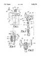
- FIG. 1is a side view illustrating a preferred embodiment of the present invention
- FIG. 2is an exploded fragmentary view illustrating a portion of the preferred embodiment of the present invention:
- FIG. 3is a longitudinal sectional view illustrating the preferred embodiment of the present invention.
- FIG. 4is a sectional view taken along line 4--4 in FIG. 3.
- a preferred embodiment of the cover assembly 10 of the present inventionis thereshown for use with a paint can 12.
- the paint can 12includes an open top 14 having an inwardly extending chime (not shown).
- the cover assembly 10includes a lid 16 dimensioned to overlie the open top 14 of the paint can 12.
- the lid 16includes a spout 18 for dispensing paint from the can 12 while locking feet 20 selectively secure the lid 16 to the paint can 12.
- a stirring assembly 22 having an elongated shaft 24is rotatably mounted to the lid 16.
- a lower portion 26 of the shaft 24extends within the interior of the paint can 12 while an upper end 28 of the shaft 24 extends above the lid 16.
- a paddle 30is secured to the lower end 26 of the shaft 24 so that rotation of the shaft 24 rotatably drives the paddle 30 and stirs the paint within the can 12.
- the cover assembly 10 of the present inventionis intended to be used in automatic stirring equipment of the type used in automotive body shops.
- the cover assembly 10includes a driven member 32 which is secured to the upper end 28 of the shaft 24.
- the driven member 32includes, for example, a pair of ears 34 which cooperate with a drive member 36 in the automatic paint stirring rack 38 (illustrated only diagrammatically). Consequently, with the paint can 12 positioned within the rack so that the drive member 36 and driven member 32 drivingly engage each other, the paint within the paint can 12 is continuously stirred.
- FIGS. 2-4a preferred embodiment of the means for adjustably securing the driven member 32 to the upper end 28 of the shaft 24 is thereshown in which the upper end 28 of the shaft 24 has a plurality of axially spaced and transversely extending slots 40 formed near the upper end 28 of the shaft 24. As best shown in FIG. 3, these slots 40 are substantially V-shaped in cross section.
- the driven member 32includes a body 42 having a throughbore 44 through which the upper end 28 of the shaft 24 extends. Furthermore, both the throughbore 44 and upper end 28 of the shaft 24 are non-circular in cross sectional shape so that, with the shaft 24 positioned through the body throughbore 44 as shown in FIGS. 3 and 4, rotation of the driven member 32 simultaneously rotatably drives the shaft 24.
- the body 42also includes a pair of upwardly extending ears 46 which cooperate with the drive mechanism 36 (FIG. 1) in the paint can rack.
- an axially extending slot 48is formed along one side of the body 42 and this slot 48 terminates in a channel 50 (FIG. 3) in the body 42 of the driven member 32. Both the channel 50 and slot 48 extend generally axially along the driven member 32.
- a locking dog 54has an upper portion 56 which is slidably received through the channel 50 to the position shown in FIG. 3. In doing so, a lower portion 58 of the locking dog 54 is positioned within the body slot 48.
- the upper portion 56 of the locking dog 54also includes a pair of opposed locking tabs 60 which engage recesses 62 (FIG. 4) formed in the body 42 in order to secure the locking dog 54 to the body 42 of the driven member 32.
- a radially inwardly extending detent 64is formed at its lowermost end of the locking dog 54 and the detent 64 which is dimensioned so that it is nestingly received within one of the transverse slots 40 formed on the shaft 24.
- the locking dog 54is constructed of a resilient material, such as plastic, nylon or the like so that the locking dog 54 is movable between the radially outer or unlocked position, illustrated in phantom line in FIG. 3, and the radially inner or locked position, illustrated in solid line in FIG. 3.
- the locking dog 54is sufficiently flexible so that the driven member 32, together with the locking dog 54, can be manually axially moved relative to the shaft 24. Such manual movement of the driven member 32 causes the locking dog 54 to flex between its locked and unlocked position as the locking dog detent 64 sequentially registers and is received within the adjacent slots 40 on the shaft 24. However, upon release of the driven member 32, the locking dog detent 64 resiliently engages and rests within one of the slots 40 thereby automatically locking the driven member 32 against further axial movement to the drive shaft 24.
- the present inventionprovides a cover assembly for a paint can for use with automatic stirring equipment in which the driven member 32 on the cover assembly 10 can be easily manually axially adjusted on the shaft 24 and, upon release, automatically locked into position. All this can be achieved, furthermore, without the use of tools. Furthermore, adjustment of the driven member 32 along the shaft 24 can be rapidly accomplished.
Landscapes
- Chemical & Material Sciences (AREA)
- Chemical Kinetics & Catalysis (AREA)
- Accessories For Mixers (AREA)
- Mixers Of The Rotary Stirring Type (AREA)
- Coating Apparatus (AREA)
Abstract
Description
1. Field of the Invention
The present invention relates to paint can cover assemblies of the type used in automatic mixing systems.
2. Description of the Prior Art
There are a number of previously known cover assemblies for paint cans. These previously known cover assemblies are designed to overlie the open top of the paint can and are secured to the paint can chime by locking feet. Furthermore, many of these cover assemblies include spouts and closure assemblies associated with the spouts to allow the paint to be dispensed from the can.
These previously known cover assemblies further included a mixing assembly. Typically, the mixing assembly included an elongated shaft extending through the paint can lid so that a lower end of the shaft was positioned within the interior of the paint can while an upper end of the shaft extended upwardly above the paint can lid. A paddle was secured to the lower end of the shaft while a driven member is secured to the upper end of the shaft.
These previously known paint can assemblies are typically used with automatic stirring equipment of the type used in automotive body repair shops and the like. Such paint stirring equipment includes a rack in which the paint cans with their attached cover assemblies are positioned. Furthermore, once the paint cans are positioned within the paint can rack, a drive member in the rack engages and cooperates with the driven member to rotatably drive the driven member with its attached paddle as long as the paint can is positioned within the rack. In this fashion, the paint cans can be stored indefinitely within the rack while insuring that the paint remains in a stirred and thus a ready to use condition.
In order for the driven member on the cover assembly to cooperate with the drive member in the paint rack, it is necessary that the driven member when attached to the paint can is vertically positioned at the proper height so that the driven member can mechanically engage and cooperate with the drive member from the paint can rack. Consequently, it is oftentimes necessary to adjust the axial position of the driven member relative to the shaft in order that the driven member on the shaft properly meshes and cooperates with the drive member from the paint can rack.
Previously, a simple set screw is threaded radially through the driven member against a flat formed in the shaft. In order to adjust the position of the driven member on the shaft, the set screw is loosened by a screw driver, repositioned to the desired position, and then retightened.
There are several disadvantages to the adjustment means for these previously known driven members. One disadvantage is that it is necessary to have the proper tool, i.e. a screw driver, in order to adjust the position of the driven member relative to its shaft. Oftentimes a screw driver is not readily available.
A still further disadvantage of these previously known adjustment means for the driven member is that frequently several adjustments often are required in order to properly position the driven member on its shaft. Each such adjustment requires that the Allen screw be loosened, the driven member readjusted, and the screw retightened. This is time consuming and, therefore, disadvantageous.
The present invention provides a cover assembly for a paint can which overcomes all of the above mentioned disadvantages of the previously known devices.
In brief, the cover assembly of the present invention comprises a lid and locking feet which detachably secure the lid to the paint can so that the lid overlies the open top of the paint can. A spout is also provided on the lid for dispensing paint from the paint can.
An elongated shaft is rotatably positioned to the lid so that a lower end of the shaft is positioned within the interior of the can while an upper end of the shaft projects upwardly from the top of the lid. A paddle is secured to the lower end of the shaft so that rotation of the shaft stirs the contents of the paint can.
A driven member is secured to the upper end of the shaft so that the driven member is positioned above the paint can lid. This driven member, in turn, cooperates with a drive member in the rack of automatic stirring equipment of the type used in automotive body shops.
Unlike the previously known driven members, however, the axial position of the driven member relative to the shaft can be manually positioned by the user without tools and, once axially adjusted to the desired position, automatically locked against further axial movement. In the preferred embodiment, the shaft includes a plurality of transversely extending and axially spaced slots formed along the upper end of the shaft. A resilient locking dog in turn is secured to the driven member and includes a detent which nests and is received within one of the slots on the shaft and, in doing so, locks the driven member against axial movement relative to the shaft. The locking dog, however, is constructed of a resilient material such that the driven member can be manually moved along the shaft and, in doing so, the locking dog deflects between a radially inner position and a radially outer position to enable the locking dog detent to move from one shaft slot to the next shaft slot.
A better understanding of the present invention will be had upon reference to the following detailed description, when read in conjunction with the accompanying drawing, wherein like reference characters refer to like parts throughout the several views, and in which:
FIG. 1 is a side view illustrating a preferred embodiment of the present invention;
FIG. 2 is an exploded fragmentary view illustrating a portion of the preferred embodiment of the present invention:
FIG. 3 is a longitudinal sectional view illustrating the preferred embodiment of the present invention; and
FIG. 4 is a sectional view taken alongline 4--4 in FIG. 3.
With reference first to FIG. 1, a preferred embodiment of thecover assembly 10 of the present invention is thereshown for use with a paint can 12. The paint can 12 includes anopen top 14 having an inwardly extending chime (not shown).
Thecover assembly 10 includes alid 16 dimensioned to overlie theopen top 14 of the paint can 12. Thelid 16 includes aspout 18 for dispensing paint from thecan 12 while lockingfeet 20 selectively secure thelid 16 to the paint can 12.
Still referring to FIG. 1, a stirringassembly 22 having anelongated shaft 24 is rotatably mounted to thelid 16. Alower portion 26 of theshaft 24 extends within the interior of the paint can 12 while anupper end 28 of theshaft 24 extends above thelid 16. Apaddle 30 is secured to thelower end 26 of theshaft 24 so that rotation of theshaft 24 rotatably drives thepaddle 30 and stirs the paint within thecan 12.
Thecover assembly 10 of the present invention is intended to be used in automatic stirring equipment of the type used in automotive body shops. As such, thecover assembly 10 includes a drivenmember 32 which is secured to theupper end 28 of theshaft 24. The drivenmember 32 includes, for example, a pair ofears 34 which cooperate with adrive member 36 in the automatic paint stirring rack 38 (illustrated only diagrammatically). Consequently, with the paint can 12 positioned within the rack so that thedrive member 36 and drivenmember 32 drivingly engage each other, the paint within the paint can 12 is continuously stirred.
In order to insure the proper driving engagement between thedrive member 36 and drivenmember 32, it is oftentimes necessary to adjust the axial position of the drivenmember 32 relative to theshaft 24.
With reference then to FIGS. 2-4, a preferred embodiment of the means for adjustably securing the drivenmember 32 to theupper end 28 of theshaft 24 is thereshown in which theupper end 28 of theshaft 24 has a plurality of axially spaced and transversely extendingslots 40 formed near theupper end 28 of theshaft 24. As best shown in FIG. 3, theseslots 40 are substantially V-shaped in cross section.
The drivenmember 32 includes abody 42 having athroughbore 44 through which theupper end 28 of theshaft 24 extends. Furthermore, both thethroughbore 44 andupper end 28 of theshaft 24 are non-circular in cross sectional shape so that, with theshaft 24 positioned through thebody throughbore 44 as shown in FIGS. 3 and 4, rotation of the drivenmember 32 simultaneously rotatably drives theshaft 24. Thebody 42 also includes a pair of upwardly extendingears 46 which cooperate with the drive mechanism 36 (FIG. 1) in the paint can rack.
Referring again to FIGS. 2-4, an axially extendingslot 48 is formed along one side of thebody 42 and thisslot 48 terminates in a channel 50 (FIG. 3) in thebody 42 of the drivenmember 32. Both thechannel 50 andslot 48 extend generally axially along the drivenmember 32.
As best shown in FIGS. 2 and 3, alocking dog 54 has anupper portion 56 which is slidably received through thechannel 50 to the position shown in FIG. 3. In doing so, alower portion 58 of the lockingdog 54 is positioned within thebody slot 48. Theupper portion 56 of the lockingdog 54 also includes a pair of opposed lockingtabs 60 which engage recesses 62 (FIG. 4) formed in thebody 42 in order to secure the lockingdog 54 to thebody 42 of the drivenmember 32.
With reference now especially to FIG. 3, a radially inwardly extendingdetent 64 is formed at its lowermost end of the lockingdog 54 and thedetent 64 which is dimensioned so that it is nestingly received within one of thetransverse slots 40 formed on theshaft 24. Furthermore, the lockingdog 54 is constructed of a resilient material, such as plastic, nylon or the like so that the lockingdog 54 is movable between the radially outer or unlocked position, illustrated in phantom line in FIG. 3, and the radially inner or locked position, illustrated in solid line in FIG. 3.
The lockingdog 54 is sufficiently flexible so that the drivenmember 32, together with the lockingdog 54, can be manually axially moved relative to theshaft 24. Such manual movement of the drivenmember 32 causes the lockingdog 54 to flex between its locked and unlocked position as the lockingdog detent 64 sequentially registers and is received within theadjacent slots 40 on theshaft 24. However, upon release of the drivenmember 32, the lockingdog detent 64 resiliently engages and rests within one of theslots 40 thereby automatically locking the drivenmember 32 against further axial movement to thedrive shaft 24.
From the foregoing, it can be seen that the present invention provides a cover assembly for a paint can for use with automatic stirring equipment in which the drivenmember 32 on thecover assembly 10 can be easily manually axially adjusted on theshaft 24 and, upon release, automatically locked into position. All this can be achieved, furthermore, without the use of tools. Furthermore, adjustment of the drivenmember 32 along theshaft 24 can be rapidly accomplished.
Having described my invention, however, many modifications thereto will become apparent to those skilled in the art to which it pertains without deviation from the spirit of the invention as defined by the scope of the appended claims.
Claims (9)
1. A cover assembly for a paint can having an open top and an inwardly extending chime, said cover assembly comprising:
a lid dimensioned to overlie the open top of the paint can, said lid having a spout,
means for detachably securing said lid to the paint can so that said lid overlies the open top of the paint can,
means for stirring the contents of the paint can, said stirring means comprising an elongated shaft, means for rotatably mounting said shaft to said lid so that an upper end of said shaft extends above said lid and a lower end of said shaft extends into an interior of the paint can, and a paddle secured to said lower end of said shaft,
a driven member, and
means for manually axially adjustably lockingly securing said driven member to said upper end of said shaft,
wherein said shaft has plurality of axially spaced notches, and wherein said securing means comprises a locking dog carried by said driven member, said locking dog having a detent which is resiliently urged toward said shaft and nestingly received in one of said shaft notches.
2. The invention as defined in claim 1 wherein said driven member comprises a body having a throughbore through which said shaft extends and a pair of spaced apart ears, said ears adapted to be driven by a drive mechanism.
3. The invention as defined in claim 1 and comprising means for attaching said locking dog to said driven member, wherein said means for attaching said locking dog to said driven member comprises a pair of opposed locking tabs on said locking dog, said locking tabs being received within recesses formed on said driven member.
4. The invention as defined in claim 1 wherein said driven member includes an axially extending slot, said locking dog being positioned within said driven member slot.
5. The invention as defined in claim 4 wherein said locking dog is constructed of plastic.
6. The invention as defined in claim 4 wherein said slot registers with a bore formed in said driven member, an upper portion of said locking dog being positioned within said bore, said upper detention of said locking dog being secured against movement to said driven member.
7. The invention as defined in claim 1 wherein said shaft has a plurality of axially spaced and transversely extending notches, and wherein said securing means comprises a locking dog radially flexibly mounted to said driven member between a radially outer position in which said driven member is freely slidable along said shaft and a radially inner position in which a portion of said locking dog is positioned within one of said notches to thereby prevent axial movement of said driven member relative to said shaft.
8. The invention as defined in claim 1 wherein said shaft notches extend transversely across one side of said shaft.
9. A cover assembly for a paint can having an open top and an inwardly extending chime, said cover assembly comprising:
a lid dimensioned to overlie the open top of the paint can, said lid having a spout,
means for detachably securing said lid to the paint can so that said lid overlies the open top of the paint can,
means for stirring the contents of the paint can, said stirring means comprising an elongated shaft, means for rotatably mounting said shaft to said lid so that an upper end of said shaft extends above said like and a lower end of said shaft extends into an interior of the paint can, and paddle secured to said lower end of said shaft,
a driven member, and
means for manually axially adjustably lockingly securing said driven member to said upper end of said shaft wherein said shaft has a plurality of axially spaced and transversely extending notches, and wherein said securing means comprises a locking dog radially flexibly mounted to said driven member between a radially outer position in which said driven member is freely slidable along said shaft and a radially inner position in which a portion of said locking dog is positioned within one of said notches to thereby prevent axial movement of said driven member relative to said shaft.
Priority Applications (1)
| Application Number | Priority Date | Filing Date | Title |
|---|---|---|---|
| US08/263,784US5482370A (en) | 1994-06-22 | 1994-06-22 | Paint can cover assembly |
Applications Claiming Priority (1)
| Application Number | Priority Date | Filing Date | Title |
|---|---|---|---|
| US08/263,784US5482370A (en) | 1994-06-22 | 1994-06-22 | Paint can cover assembly |
Publications (1)
| Publication Number | Publication Date |
|---|---|
| US5482370Atrue US5482370A (en) | 1996-01-09 |
Family
ID=23003217
Family Applications (1)
| Application Number | Title | Priority Date | Filing Date |
|---|---|---|---|
| US08/263,784Expired - LifetimeUS5482370A (en) | 1994-06-22 | 1994-06-22 | Paint can cover assembly |
Country Status (1)
| Country | Link |
|---|---|
| US (1) | US5482370A (en) |
Cited By (20)
| Publication number | Priority date | Publication date | Assignee | Title |
|---|---|---|---|---|
| WO1997034775A1 (en)* | 1996-03-18 | 1997-09-25 | Tecmec S.R.L. | Mixing cover for paint vessels and the like |
| US5947598A (en)* | 1998-09-15 | 1999-09-07 | Dedoes Industries, Inc. | Automatic paint stirring equipment with improved driving means |
| US5988868A (en)* | 1998-09-15 | 1999-11-23 | Dedoes Industries, Inc. | Drive member for automatic paint stirring equipment |
| US6053218A (en)* | 1998-11-10 | 2000-04-25 | X-Pert Paint Mixing Systems, Inc. | Semi-automated system for dispensing automotive paint |
| US6095373A (en)* | 1998-11-10 | 2000-08-01 | X-Pert Paint Mixing Systems, Inc. | Paint container lid for a semi-automated automotive paint dispensing system |
| US6146009A (en)* | 1999-10-13 | 2000-11-14 | X-Pert Paint Mixing Systems, Inc. | Paint container lid member adaptable for use with a plurality of paint mixing systems |
| US6206250B1 (en) | 1999-10-13 | 2001-03-27 | X-Pert Paint Mixing Systems, Inc. | Lid member for a paint container useable with a semi-automated automotive paint dispensing system |
| US6230938B1 (en) | 1999-10-13 | 2001-05-15 | X-Pert Paint Mixing Systems, Inc. | Seal structure for a fluid pour spout of a paint container lid member |
| US6234218B1 (en) | 1999-10-13 | 2001-05-22 | X-Pert Paint Mixing Systems, Inc. | Semi-automated automotive paint dispensing system |
| US6336740B1 (en) | 2001-04-05 | 2002-01-08 | Dedoes Industries, Inc. | Cover assembly with improved locking feet |
| EP0904829B1 (en)* | 1997-09-19 | 2003-02-26 | F.A.S. Société Anonyme dite: | Collar for positioning the axial height of an agitator of a agitating cover destined to be used to stir paints |
| US6702144B1 (en) | 2002-12-04 | 2004-03-09 | David E. Lyon | Can apron |
| US20040090861A1 (en)* | 2002-09-03 | 2004-05-13 | Kitson George A. S. | Container stirring mechanism |
| US20040233777A1 (en)* | 2003-05-20 | 2004-11-25 | Adams Roger W. | Paint container and colorant injector apparatus and method |
| US20060000838A1 (en)* | 2004-06-02 | 2006-01-05 | Peter Santrach | Self-cleaning lid for a paint container fluid pour spout |
| US20060185524A1 (en)* | 2005-02-18 | 2006-08-24 | Dedoes Industries, Inc. | Stirring device for a paint pot, with modifiable functions, in a plastic material |
| US20070060203A1 (en)* | 1993-10-13 | 2007-03-15 | Dataquill Limited | Data entry systems |
| USRE39732E1 (en)* | 1995-12-08 | 2007-07-17 | Fillon Investissement | Driving head for stirrer cans |
| GB2434997A (en)* | 2006-02-11 | 2007-08-15 | Daniel Bolton | Paint stirring tin |
| WO2009153522A1 (en)* | 2008-06-20 | 2009-12-23 | Fillon Technologies | Agitation device, and adjustment method thereof |
Citations (5)
| Publication number | Priority date | Publication date | Assignee | Title |
|---|---|---|---|---|
| US2269736A (en)* | 1940-09-06 | 1942-01-13 | Leon Finch Ltd | Dispensing device |
| US3041052A (en)* | 1959-07-10 | 1962-06-26 | Arnold A Dedoes | Paint mixing and blending apparatus |
| US4407584A (en)* | 1980-02-11 | 1983-10-04 | Fonderie Et Ateliers Des Sablons | Vessel lid especially for a mixer used for the homogenization of a mixture of products |
| US5094543A (en)* | 1987-07-08 | 1992-03-10 | Laszlo Mursa | Paint mixing container |
| US5368389A (en)* | 1992-06-22 | 1994-11-29 | Dedoes Industries, Inc. | Paint can cover assembly |
- 1994
- 1994-06-22USUS08/263,784patent/US5482370A/ennot_activeExpired - Lifetime
Patent Citations (5)
| Publication number | Priority date | Publication date | Assignee | Title |
|---|---|---|---|---|
| US2269736A (en)* | 1940-09-06 | 1942-01-13 | Leon Finch Ltd | Dispensing device |
| US3041052A (en)* | 1959-07-10 | 1962-06-26 | Arnold A Dedoes | Paint mixing and blending apparatus |
| US4407584A (en)* | 1980-02-11 | 1983-10-04 | Fonderie Et Ateliers Des Sablons | Vessel lid especially for a mixer used for the homogenization of a mixture of products |
| US5094543A (en)* | 1987-07-08 | 1992-03-10 | Laszlo Mursa | Paint mixing container |
| US5368389A (en)* | 1992-06-22 | 1994-11-29 | Dedoes Industries, Inc. | Paint can cover assembly |
Cited By (32)
| Publication number | Priority date | Publication date | Assignee | Title |
|---|---|---|---|---|
| US20070060203A1 (en)* | 1993-10-13 | 2007-03-15 | Dataquill Limited | Data entry systems |
| USRE39732E1 (en)* | 1995-12-08 | 2007-07-17 | Fillon Investissement | Driving head for stirrer cans |
| WO1997034775A1 (en)* | 1996-03-18 | 1997-09-25 | Tecmec S.R.L. | Mixing cover for paint vessels and the like |
| EP0904829B1 (en)* | 1997-09-19 | 2003-02-26 | F.A.S. Société Anonyme dite: | Collar for positioning the axial height of an agitator of a agitating cover destined to be used to stir paints |
| US5947598A (en)* | 1998-09-15 | 1999-09-07 | Dedoes Industries, Inc. | Automatic paint stirring equipment with improved driving means |
| US5988868A (en)* | 1998-09-15 | 1999-11-23 | Dedoes Industries, Inc. | Drive member for automatic paint stirring equipment |
| US6053218A (en)* | 1998-11-10 | 2000-04-25 | X-Pert Paint Mixing Systems, Inc. | Semi-automated system for dispensing automotive paint |
| US6095373A (en)* | 1998-11-10 | 2000-08-01 | X-Pert Paint Mixing Systems, Inc. | Paint container lid for a semi-automated automotive paint dispensing system |
| US6755326B2 (en) | 1999-10-13 | 2004-06-29 | X-Pert Paint Mixing Systems, Inc. | Seal structure for a fluid pour spout of a paint container lid member |
| US6234218B1 (en) | 1999-10-13 | 2001-05-22 | X-Pert Paint Mixing Systems, Inc. | Semi-automated automotive paint dispensing system |
| US6290110B1 (en) | 1999-10-13 | 2001-09-18 | X-Pert Paint Mixing Systems, Inc. | Fluid seal for a pour spout of a paint container lid member |
| US6474516B2 (en) | 1999-10-13 | 2002-11-05 | X-Pert Paint Mixing Systems, Inc. | Seal structure for a fluid pour spout of a paint container lid member |
| US6230938B1 (en) | 1999-10-13 | 2001-05-15 | X-Pert Paint Mixing Systems, Inc. | Seal structure for a fluid pour spout of a paint container lid member |
| US6146009A (en)* | 1999-10-13 | 2000-11-14 | X-Pert Paint Mixing Systems, Inc. | Paint container lid member adaptable for use with a plurality of paint mixing systems |
| US6206250B1 (en) | 1999-10-13 | 2001-03-27 | X-Pert Paint Mixing Systems, Inc. | Lid member for a paint container useable with a semi-automated automotive paint dispensing system |
| WO2001026789A1 (en)* | 1999-10-13 | 2001-04-19 | X-Pert Paint Mixing Systems, Inc. | Universal paint container lid member |
| US6336740B1 (en) | 2001-04-05 | 2002-01-08 | Dedoes Industries, Inc. | Cover assembly with improved locking feet |
| US20040090861A1 (en)* | 2002-09-03 | 2004-05-13 | Kitson George A. S. | Container stirring mechanism |
| US6702144B1 (en) | 2002-12-04 | 2004-03-09 | David E. Lyon | Can apron |
| WO2004103727A3 (en)* | 2003-05-20 | 2005-08-11 | Roger W Adams | Paint container and colorant injector apparatus and method |
| US20040233777A1 (en)* | 2003-05-20 | 2004-11-25 | Adams Roger W. | Paint container and colorant injector apparatus and method |
| US7086776B2 (en) | 2003-05-20 | 2006-08-08 | Adams Roger W | Paint container and colorant injector apparatus and method |
| US20060000838A1 (en)* | 2004-06-02 | 2006-01-05 | Peter Santrach | Self-cleaning lid for a paint container fluid pour spout |
| US8424704B2 (en) | 2004-06-02 | 2013-04-23 | X-Pert Paint Mixing Systems, Inc. | Self-cleaning lid for a paint container fluid pour spout |
| US20060185524A1 (en)* | 2005-02-18 | 2006-08-24 | Dedoes Industries, Inc. | Stirring device for a paint pot, with modifiable functions, in a plastic material |
| US7607820B2 (en)* | 2005-02-18 | 2009-10-27 | Dedoes Industries, Inc. | Stirring device for a paint pot, with modifiable functions, in a plastic material |
| GB2434997A (en)* | 2006-02-11 | 2007-08-15 | Daniel Bolton | Paint stirring tin |
| WO2009153522A1 (en)* | 2008-06-20 | 2009-12-23 | Fillon Technologies | Agitation device, and adjustment method thereof |
| FR2932697A1 (en)* | 2008-06-20 | 2009-12-25 | Fillon Technologies | AGITATION DEVICE AND METHOD OF ADJUSTING |
| US20110103177A1 (en)* | 2008-06-20 | 2011-05-05 | Fillon Technologies | Stirrer device and a method of adjusting it |
| CN102065986A (en)* | 2008-06-20 | 2011-05-18 | 飞勇科技公司 | Agitation device, and adjustment method thereof |
| US8899825B2 (en) | 2008-06-20 | 2014-12-02 | Fillon Technologies | Stirrer device and a method of adjusting it |
Similar Documents
| Publication | Publication Date | Title |
|---|---|---|
| US5482370A (en) | Paint can cover assembly | |
| US7104738B2 (en) | Hole saw arbor | |
| US5368389A (en) | Paint can cover assembly | |
| EP1496342B1 (en) | Weighing apparatus with a device forming foot-support | |
| EP0579889B1 (en) | Mixer and attachment | |
| DE20021784U1 (en) | Laser leveler with protective housing | |
| DE19628552A1 (en) | Anti-cross contamination double cartridge dispenser | |
| US5622289A (en) | Paint can cover assembly | |
| DE602005003306T2 (en) | Support bracket for sensors on a vehicle wheel | |
| US6474516B2 (en) | Seal structure for a fluid pour spout of a paint container lid member | |
| AU1499292A (en) | Improvement relating to pouring devices for viscous liquid such as paint | |
| EP2140931B2 (en) | Agitating machine with length-adjustable tool holder | |
| EP0987056A3 (en) | Automatic paint mixing machine | |
| ATE169592T1 (en) | DEVICE FOR LOADING A SILO VEHICLE | |
| DE8122466U1 (en) | MIXING DEVICE, IN PARTICULAR COLOR MIXING DEVICE | |
| EP1095819A1 (en) | Holding device for an object in a motor vehicle | |
| US6634785B2 (en) | Mixer assembly | |
| US20050094487A1 (en) | Automatic paint stirring equipment | |
| EP0143145B1 (en) | Rack for storing lacquer tins | |
| EP1246739B1 (en) | Holder device for drinks containers | |
| CH633977A5 (en) | EXCHANGEABLE BURETTES. | |
| DE3708635C2 (en) | Manually operated crank drive for vehicle roofs | |
| DE3689028T2 (en) | Coupling and weighing device for a dispenser of carbonated beverages. | |
| EP0960777A2 (en) | Storage compartment in a vehicle | |
| US3816009A (en) | Latch fastener |
Legal Events
| Date | Code | Title | Description |
|---|---|---|---|
| AS | Assignment | Owner name:DEDOES INDUSTRIES, INC., MICHIGAN Free format text:ASSIGNMENT OF ASSIGNORS INTEREST;ASSIGNOR:DEDOES, JOHN T.;REEL/FRAME:007055/0116 Effective date:19940525 | |
| STCF | Information on status: patent grant | Free format text:PATENTED CASE | |
| CC | Certificate of correction | ||
| FPAY | Fee payment | Year of fee payment:4 | |
| FPAY | Fee payment | Year of fee payment:8 | |
| FPAY | Fee payment | Year of fee payment:12 | |
| AS | Assignment | Owner name:DEDOES INDUSTRIES LLC, MICHIGAN Free format text:ASSIGNMENT OF ASSIGNORS INTEREST;ASSIGNOR:DEDOES INDUSTRIES, INC;REEL/FRAME:054621/0198 Effective date:20201205 | |
| AS | Assignment | Owner name:BMO HARRIS BANK N.A., ILLINOIS Free format text:SECURITY INTEREST;ASSIGNOR:DEDOES INDUSTRIES LLC;REEL/FRAME:054690/0097 Effective date:20201210 |