US5481939A - Cable strain relief device - Google Patents
Cable strain relief deviceDownload PDFInfo
- Publication number
- US5481939A US5481939AUS08/174,356US17435693AUS5481939AUS 5481939 AUS5481939 AUS 5481939AUS 17435693 AUS17435693 AUS 17435693AUS 5481939 AUS5481939 AUS 5481939A
- Authority
- US
- United States
- Prior art keywords
- disks
- openings
- cable
- disk
- offset
- Prior art date
- Legal status (The legal status is an assumption and is not a legal conclusion. Google has not performed a legal analysis and makes no representation as to the accuracy of the status listed.)
- Expired - Lifetime
Links
- 230000000717retained effectEffects0.000claimsabstractdescription4
- 230000037361pathwayEffects0.000abstract1
- 239000002184metalSubstances0.000description10
- 210000005069earsAnatomy0.000description3
- 239000004744fabricSubstances0.000description2
- 239000000463materialSubstances0.000description2
- 238000003491arrayMethods0.000description1
- 230000000712assemblyEffects0.000description1
- 238000000429assemblyMethods0.000description1
- 230000015572biosynthetic processEffects0.000description1
- 238000000034methodMethods0.000description1
- 229920000642polymerPolymers0.000description1
- 238000000926separation methodMethods0.000description1
Images


Classifications
- H—ELECTRICITY
- H01—ELECTRIC ELEMENTS
- H01R—ELECTRICALLY-CONDUCTIVE CONNECTIONS; STRUCTURAL ASSOCIATIONS OF A PLURALITY OF MUTUALLY-INSULATED ELECTRICAL CONNECTING ELEMENTS; COUPLING DEVICES; CURRENT COLLECTORS
- H01R13/00—Details of coupling devices of the kinds covered by groups H01R12/70 or H01R24/00 - H01R33/00
- H01R13/58—Means for relieving strain on wire connection, e.g. cord grip, for avoiding loosening of connections between wires and terminals within a coupling device terminating a cable
- H01R13/5804—Means for relieving strain on wire connection, e.g. cord grip, for avoiding loosening of connections between wires and terminals within a coupling device terminating a cable comprising a separate cable clamping part
- H—ELECTRICITY
- H02—GENERATION; CONVERSION OR DISTRIBUTION OF ELECTRIC POWER
- H02G—INSTALLATION OF ELECTRIC CABLES OR LINES, OR OF COMBINED OPTICAL AND ELECTRIC CABLES OR LINES
- H02G15/00—Cable fittings
- H02G15/007—Devices for relieving mechanical stress
- Y—GENERAL TAGGING OF NEW TECHNOLOGICAL DEVELOPMENTS; GENERAL TAGGING OF CROSS-SECTIONAL TECHNOLOGIES SPANNING OVER SEVERAL SECTIONS OF THE IPC; TECHNICAL SUBJECTS COVERED BY FORMER USPC CROSS-REFERENCE ART COLLECTIONS [XRACs] AND DIGESTS
- Y10—TECHNICAL SUBJECTS COVERED BY FORMER USPC
- Y10T—TECHNICAL SUBJECTS COVERED BY FORMER US CLASSIFICATION
- Y10T74/00—Machine element or mechanism
- Y10T74/20—Control lever and linkage systems
- Y10T74/20396—Hand operated
- Y10T74/20402—Flexible transmitter [e.g., Bowden cable]
- Y10T74/2045—Flexible transmitter [e.g., Bowden cable] and sheath support, connector, or anchor
Definitions
- the inventionrelates generally to cable strain relief devices.
- strain relief devicesare known in the prior art.
- the strain relief device of the present deviceprovides an elegant solution, with disks having offset openings oriented and retained in a backshell and backnut assembly to form a simple and effective strain relief device.
- the present inventionrelates to cable strain relief devices comprising a pair of disks each having an opening therein sized to allow a cable to be passed therethrough and means to maintain such disks in a position relative to one another such that the openings are proximate and offset whereby cable passed through said openings is kinked and retained thereatween. It is possible to use more than two disks, although, not necessary, whereby a plurality of kinks in series are formed.
- Identical disksmay be used in which the opening in each disk is offset from the disk center.
- the disksare positioned relative to one another to offset the openings therein whereby when the disks are brought close to one another, the offset causes the cable to kink between the proximal opposing disk faces.
- the preferred means to maintain the disk in position relative to one anotheris a backshell and backnut assembly.
- the disksmay have one or a plurality of openings therein, sized to allow cables to be passed therethrough.
- the diskshave tabs and the backshell has recesses.
- the tabs of said disksare inserted within the recesses to maintain the disks in position relative to one another.
- diskshave recesses and said backshell has ridges which fit within the recesses to maintain the disks in position relative to one another.
- a particularly preferred disk architectureis one having a plurality of openings.
- One of the openingsis offset from the central longitudinal axis of the disk.
- Such central openingis surrounded (encircled) by other openings.
- the encircling openingsare positioned relative to the central opening, such that a circle having a radius originating at the center of the center opening and circumscribing the center opening passes through the center of the other encircling openings.
- the strain relief mechanism of the present inventionmay be used for gripping a single cable or a multiplicity of cables.
- the term "cable” as used hereinrefers to conduits, wires, and a variety of cables which may vary in architecture, which include specifically, electric cables, that may be polymer and/or metal fabric or mesh sheathed.
- the inventionwhere electric cable is used, involves the use of a non-conductive disk with a single hole or multiplicity of holes (sized for the cable) which are offset slightly from lines of symmetry such that when two identical disks are used when one is reversed with respect to the other, there is an offset of the matching holes.
- a cableis passed through these holes with the disks spread apart, the cable passes easily.
- the offsetcauses a slight kink in the cable which prevents the cable from being pulled out.
- the material selected for the diskis not a part of the present invention.
- the diskcan suitably be made of metal, but for both safety and economy, plastic is the material of choice.
- the cables, wires, conduits and the likemay have resilient outer surfaces or be encased in a rigid sheath, such as a metal fabric sheath. For the latter, a metal disk is utilized.
- an important embodiment of the present inventionrelates to the use of conductive disks, most suitably metal, to provide a terminus for shielded cables through the body of the connector to ground.
- the cable(s)are metal sheathed and the metal braid forms a metal to metal conductive path with one or the other or both disks.
- At least one of the disksis electrically conductive, preferably metal and connected to ground.
- strain relief disks as herein notedare preferably housed in an assembly comprising a backshell and a backnut.
- various disk positioning meanssuch as tabs and notches are preferred, the disks may be positioned by compressing same to form the requisite cable kink simply by using screws passed through the disks, or by using clamps or the like.
- the diskcan be of any geometry; and, when the means of maintaining disks in oriented position comprises a backshell, the disk may be round, with or without tabs, elliptical, triangular, polygonal, suitably with the perimeter of the disk interfitting within the interior of the backshell.
- the exterior of the backshellneeds to be of architecture appropriate to the backnut for engagement and application of torque to bring the disks into proximity to one another to kink the cable; the most facile, though not only engagement method, being a thread engagement system typically used in backshell and backnut assemblies.
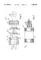
- FIG. 1is a side elevational view of the cable strain relief device of the present invention.
- FIG. 2is an exploded sectional view of the cable strain relief device of FIG. 1 with the cables shown in phantom.
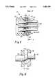
- FIG. 3ais a front plan view of a disk of the present invention.
- FIG. 3bis a rear plan view of the disk shown in 3a.
- FIG. 4is a front view of paired disks illustrating overlap of the openings.
- FIG. 5is a partial sectional view of the present invention in use.
- FIG. 6is a partial view taken from FIG. 5.
- FIG. 7is a sectional view taken from 7--7 of FIG. 5.
- FIG. 8is a front elevational view of a notched disk.
- FIG. 9is a sectional view illustrating the embodiment of the invention where the disk is notched.
- the cable strain relief device 10is shown with backnut 20 engaged with backshell 30.
- inside threads 22 of backnut 20are shown, which mate with the threaded portion 32 of backshell 30.
- notch 36 in backshell 30which accepts tab 42 of disks 40 to align same.
- the opening 34 in backshell 30houses disks 40.
- the cableis shown in phantom prior to disk orientation.
- FIG. 3aillustrates the front face 40a of disk 40.
- the disk centeris shown at the intersection of A-a and the center of the central offset opening 44 is shown at B-b.
- the offsetis shown at C.
- FIG. 3billustrates the rear face 40b of disk 40.
- FIG. 4an array of two disks are arranged with rear faces 40(b) proximate showing the offset at 43.
- Such offsetas shown in FIGS. 7 and 8, when the disks are proximally oriented, causes kink 49 in cables 48.
- FIGS. 5 and 6the invention in use is shown wherein cables 48, as best shown in FIG. 6, are secured by kink 49 within separation D between disks 40 which prevents movement of the cable.
- FIG. 7a partial cross-section of FIG. 5, taken along 7--7, is shown.
- the engaged backshell and backnut assemblyis shown with the disk in oriented position and tab 42 within notch 36' which prevents rotational movement.
- notch 36'does not extend through the housing of backshell 30.
- FIGS. 8 and 9illustrate the embodiment of the invention, where the notch and tab arrangement of FIG. 7 is reversed so that the notch 52 is in the disk 50 and tab 66 extends from the interior of the backshell 60.
- Assembly of the strain relief disksprovides mechanical restraint needed for the individual cables engaged and kinked as the disks are oriented to provide offset of openings and brought toward one another to kink the cable. Assembly may be achieved by sliding the backnut rearward over a bundle of cables following by one of two disks, with side 40a side facing towards the backnut. The cables are passed through the disk openings. The second disk is slipped over the individual cables, with side 40a facing the backshell. The tabs/ears on the second disk align with those of the first disk. Finally, the backshell is slid over the cables.
- the backshellAfter terminating the cables to an electrical connector (not shown), the backshell is slipped forward.
- the first diskis positioned with its ears in slots provided in the rear of the backshell.
- the second diskis slid forward and its ears positioned at the lead in of the slots.
- the backnutis brought forward and tightened down onto the backshell. This compresses the disks together causing the individual cables to deform in the resultant offset.
- the connectoris ready for use.
- the torque requiredvaries based on the type of cable used and is readily determined for each application empirically.
- strain relief devices of the present inventionfind broad application in strain relief of a broad variety of cables individually or in plural arrays and used in other applications.
Landscapes
- Details Of Connecting Devices For Male And Female Coupling (AREA)
Abstract
Description
The invention relates generally to cable strain relief devices.
Strain relief devices are known in the prior art. The strain relief device of the present device provides an elegant solution, with disks having offset openings oriented and retained in a backshell and backnut assembly to form a simple and effective strain relief device.
The present invention relates to cable strain relief devices comprising a pair of disks each having an opening therein sized to allow a cable to be passed therethrough and means to maintain such disks in a position relative to one another such that the openings are proximate and offset whereby cable passed through said openings is kinked and retained thereatween. It is possible to use more than two disks, although, not necessary, whereby a plurality of kinks in series are formed.
Identical disks may be used in which the opening in each disk is offset from the disk center. The disks are positioned relative to one another to offset the openings therein whereby when the disks are brought close to one another, the offset causes the cable to kink between the proximal opposing disk faces.
The preferred means to maintain the disk in position relative to one another is a backshell and backnut assembly. The disks may have one or a plurality of openings therein, sized to allow cables to be passed therethrough.
In one embodiment of the invention, the disks have tabs and the backshell has recesses. The tabs of said disks are inserted within the recesses to maintain the disks in position relative to one another.
In an alternative embodiment of the invention, disks have recesses and said backshell has ridges which fit within the recesses to maintain the disks in position relative to one another.
A particularly preferred disk architecture is one having a plurality of openings. One of the openings is offset from the central longitudinal axis of the disk. Such central opening is surrounded (encircled) by other openings. The encircling openings are positioned relative to the central opening, such that a circle having a radius originating at the center of the center opening and circumscribing the center opening passes through the center of the other encircling openings.
The strain relief mechanism of the present invention may be used for gripping a single cable or a multiplicity of cables. The term "cable" as used herein refers to conduits, wires, and a variety of cables which may vary in architecture, which include specifically, electric cables, that may be polymer and/or metal fabric or mesh sheathed.
The invention, where electric cable is used, involves the use of a non-conductive disk with a single hole or multiplicity of holes (sized for the cable) which are offset slightly from lines of symmetry such that when two identical disks are used when one is reversed with respect to the other, there is an offset of the matching holes. When a cable is passed through these holes with the disks spread apart, the cable passes easily. When the disks are pressed together, the offset causes a slight kink in the cable which prevents the cable from being pulled out.
The material selected for the disk is not a part of the present invention. The disk can suitably be made of metal, but for both safety and economy, plastic is the material of choice.
The cables, wires, conduits and the like may have resilient outer surfaces or be encased in a rigid sheath, such as a metal fabric sheath. For the latter, a metal disk is utilized.
Use of electrically conductive disks, particularly where a plurality of cables are engaged in the manner of the present invention, provides a good ohmic connection to ground. Accordingly, an important embodiment of the present invention relates to the use of conductive disks, most suitably metal, to provide a terminus for shielded cables through the body of the connector to ground. Most preferably, the cable(s) are metal sheathed and the metal braid forms a metal to metal conductive path with one or the other or both disks. At least one of the disks is electrically conductive, preferably metal and connected to ground. The engagement of disks to cable, which provides kink formation, functions to provide a secure electrically conductive path.
The strain relief disks as herein noted are preferably housed in an assembly comprising a backshell and a backnut. In this regard, although various disk positioning means such as tabs and notches are preferred, the disks may be positioned by compressing same to form the requisite cable kink simply by using screws passed through the disks, or by using clamps or the like.
The disk can be of any geometry; and, when the means of maintaining disks in oriented position comprises a backshell, the disk may be round, with or without tabs, elliptical, triangular, polygonal, suitably with the perimeter of the disk interfitting within the interior of the backshell. The exterior of the backshell needs to be of architecture appropriate to the backnut for engagement and application of torque to bring the disks into proximity to one another to kink the cable; the most facile, though not only engagement method, being a thread engagement system typically used in backshell and backnut assemblies.
Referring again to orientation of openings to achieve required offset, the options are numerous. Where disks with tabs are used, there can be multiple recesses in the backshell and/or different tab locations on the disks. Where recesses in the disks are used, recess engaging ridges within the backshell can be offset from the longitudinal access of the backshell.
FIG. 1 is a side elevational view of the cable strain relief device of the present invention.
FIG. 2 is an exploded sectional view of the cable strain relief device of FIG. 1 with the cables shown in phantom.
FIG. 3a is a front plan view of a disk of the present invention.
FIG. 3b is a rear plan view of the disk shown in 3a.
FIG. 4 is a front view of paired disks illustrating overlap of the openings.
FIG. 5 is a partial sectional view of the present invention in use.
FIG. 6 is a partial view taken from FIG. 5.
FIG. 7 is a sectional view taken from 7--7 of FIG. 5.
FIG. 8 is a front elevational view of a notched disk.
FIG. 9 is a sectional view illustrating the embodiment of the invention where the disk is notched.
In FIG. 1, the cablestrain relief device 10 is shown withbacknut 20 engaged withbackshell 30. In FIG. 2, insidethreads 22 ofbacknut 20 are shown, which mate with the threadedportion 32 ofbackshell 30. Also shown isnotch 36 inbackshell 30 which acceptstab 42 ofdisks 40 to align same. The opening 34 inbackshell 30houses disks 40. In FIG. 2, the cable is shown in phantom prior to disk orientation.
FIG. 3a illustrates thefront face 40a ofdisk 40. The disk center is shown at the intersection of A-a and the center of the central offset opening 44 is shown at B-b. The offset is shown at C.
FIG. 3b illustrates therear face 40b ofdisk 40.
In FIG. 4, an array of two disks are arranged with rear faces 40(b) proximate showing the offset at 43. Such offset, as shown in FIGS. 7 and 8, when the disks are proximally oriented, causeskink 49 incables 48.
In FIGS. 5 and 6, the invention in use is shown whereincables 48, as best shown in FIG. 6, are secured bykink 49 within separation D betweendisks 40 which prevents movement of the cable.
In FIG. 7, a partial cross-section of FIG. 5, taken along 7--7, is shown. Referring to FIG. 7, the engaged backshell and backnut assembly is shown with the disk in oriented position andtab 42 within notch 36' which prevents rotational movement. In the embodiment shown in FIG. 7, notch 36' does not extend through the housing ofbackshell 30.
FIGS. 8 and 9 illustrate the embodiment of the invention, where the notch and tab arrangement of FIG. 7 is reversed so that thenotch 52 is in thedisk 50 andtab 66 extends from the interior of thebackshell 60.
Assembly of the strain relief disks provides mechanical restraint needed for the individual cables engaged and kinked as the disks are oriented to provide offset of openings and brought toward one another to kink the cable. Assembly may be achieved by sliding the backnut rearward over a bundle of cables following by one of two disks, withside 40a side facing towards the backnut. The cables are passed through the disk openings. The second disk is slipped over the individual cables, withside 40a facing the backshell. The tabs/ears on the second disk align with those of the first disk. Finally, the backshell is slid over the cables.
After terminating the cables to an electrical connector (not shown), the backshell is slipped forward. The first disk is positioned with its ears in slots provided in the rear of the backshell. The second disk is slid forward and its ears positioned at the lead in of the slots. The backnut is brought forward and tightened down onto the backshell. This compresses the disks together causing the individual cables to deform in the resultant offset. After applying adequate torque, the connector is ready for use. The torque required varies based on the type of cable used and is readily determined for each application empirically.
Although assembly is described by reference to a strain relief assembly for an electrical connector, the strain relief devices of the present invention, as will be appreciated, find broad application in strain relief of a broad variety of cables individually or in plural arrays and used in other applications.
While the best mode for carrying out the invention has been described in detail, those familiar with the art to which this invention relates will recognize various alternative designs and embodiments for practicing the invention as defined by the following claims.
Claims (1)
1. A cable strain relief device comprising:
a) a pair of disks, each of said disks having a plurality of openings therein sized to allow cables to be passed therethrough, wherein the plurality of openings on each disk is comprised of a first opening offset from the central longitudinal axis of the disk, and other openings positioned away from and around said first opening, such that a circle centered on and circumscribing the first opening passes through the center of the other openings and
b) means to maintain said disks in a position relative to one another such that the openings are proximate and offset whereby cable passed through said openings is kinked and retained therebetween.
Priority Applications (1)
| Application Number | Priority Date | Filing Date | Title |
|---|---|---|---|
| US08/174,356US5481939A (en) | 1993-12-28 | 1993-12-28 | Cable strain relief device |
Applications Claiming Priority (1)
| Application Number | Priority Date | Filing Date | Title |
|---|---|---|---|
| US08/174,356US5481939A (en) | 1993-12-28 | 1993-12-28 | Cable strain relief device |
Publications (1)
| Publication Number | Publication Date |
|---|---|
| US5481939Atrue US5481939A (en) | 1996-01-09 |
Family
ID=22635871
Family Applications (1)
| Application Number | Title | Priority Date | Filing Date |
|---|---|---|---|
| US08/174,356Expired - LifetimeUS5481939A (en) | 1993-12-28 | 1993-12-28 | Cable strain relief device |
Country Status (1)
| Country | Link |
|---|---|
| US (1) | US5481939A (en) |
Cited By (50)
| Publication number | Priority date | Publication date | Assignee | Title |
|---|---|---|---|---|
| US5742982A (en)* | 1996-11-25 | 1998-04-28 | Siecor Corporation | Cable strain relief apparatus |
| US5771576A (en)* | 1997-05-22 | 1998-06-30 | Braxton; Thomas R. | Strain relief device and method |
| DE20118749U1 (en) | 2001-11-16 | 2002-02-07 | Coninvers Elektronische Bauelemente GmbH, 71083 Herrenberg | Strain relief for single wires |
| US6454596B1 (en)* | 1999-06-30 | 2002-09-24 | Fci Americas Technology, Inc. | Electrical conductor strain relief for a printed circuit board |
| DE10121890A1 (en)* | 2001-05-05 | 2002-11-21 | Bosch Gmbh Robert | Wire feed-through has at least two molded bodies with feed through channels arranged in series in housing so wire fed through channels is bent at least twice over its feed-through length |
| US20030189149A1 (en)* | 2002-04-05 | 2003-10-09 | Leffers Murray Jones | Multiple writing, drafting and art instrument holder |
| WO2006007699A1 (en)* | 2004-07-16 | 2006-01-26 | Matthew Kennedy | Wire management device |
| US7037139B1 (en)* | 2005-02-28 | 2006-05-02 | Methode Electronics, Inc. | Wiretrap electrical connector and assembly with strain relief plate |
| US20090310928A1 (en)* | 2008-06-12 | 2009-12-17 | Wolf Kluwe | Universal cable bracket |
| US20090320636A1 (en)* | 2008-06-30 | 2009-12-31 | Shimano Inc. | Bicycle component operating device |
| US20100220967A1 (en)* | 2009-02-27 | 2010-09-02 | Cooke Terry L | Hinged Fiber Optic Module Housing and Module |
| US20110042529A1 (en)* | 2009-08-24 | 2011-02-24 | Walter Thomas Alan | Routing assembly for wires in electronic assemblies and the like |
| US8433171B2 (en) | 2009-06-19 | 2013-04-30 | Corning Cable Systems Llc | High fiber optic cable packing density apparatus |
| US8465300B2 (en)* | 2011-09-14 | 2013-06-18 | Primesource Telecom Inc. | Cable installation assembly |
| US8538226B2 (en) | 2009-05-21 | 2013-09-17 | Corning Cable Systems Llc | Fiber optic equipment guides and rails configured with stopping position(s), and related equipment and methods |
| US8542973B2 (en) | 2010-04-23 | 2013-09-24 | Ccs Technology, Inc. | Fiber optic distribution device |
| US8593828B2 (en) | 2010-02-04 | 2013-11-26 | Corning Cable Systems Llc | Communications equipment housings, assemblies, and related alignment features and methods |
| US8625950B2 (en) | 2009-12-18 | 2014-01-07 | Corning Cable Systems Llc | Rotary locking apparatus for fiber optic equipment trays and related methods |
| US8660397B2 (en) | 2010-04-30 | 2014-02-25 | Corning Cable Systems Llc | Multi-layer module |
| US8662760B2 (en) | 2010-10-29 | 2014-03-04 | Corning Cable Systems Llc | Fiber optic connector employing optical fiber guide member |
| US8699838B2 (en) | 2009-05-14 | 2014-04-15 | Ccs Technology, Inc. | Fiber optic furcation module |
| US8705926B2 (en) | 2010-04-30 | 2014-04-22 | Corning Optical Communications LLC | Fiber optic housings having a removable top, and related components and methods |
| US8712206B2 (en) | 2009-06-19 | 2014-04-29 | Corning Cable Systems Llc | High-density fiber optic modules and module housings and related equipment |
| US8718436B2 (en) | 2010-08-30 | 2014-05-06 | Corning Cable Systems Llc | Methods, apparatuses for providing secure fiber optic connections |
| US8879881B2 (en) | 2010-04-30 | 2014-11-04 | Corning Cable Systems Llc | Rotatable routing guide and assembly |
| US8913866B2 (en) | 2010-03-26 | 2014-12-16 | Corning Cable Systems Llc | Movable adapter panel |
| US20150034776A1 (en)* | 2013-07-31 | 2015-02-05 | Stryker Corporation | Line management device |
| US8953924B2 (en) | 2011-09-02 | 2015-02-10 | Corning Cable Systems Llc | Removable strain relief brackets for securing fiber optic cables and/or optical fibers to fiber optic equipment, and related assemblies and methods |
| US8985862B2 (en) | 2013-02-28 | 2015-03-24 | Corning Cable Systems Llc | High-density multi-fiber adapter housings |
| US8989547B2 (en) | 2011-06-30 | 2015-03-24 | Corning Cable Systems Llc | Fiber optic equipment assemblies employing non-U-width-sized housings and related methods |
| US8995812B2 (en) | 2012-10-26 | 2015-03-31 | Ccs Technology, Inc. | Fiber optic management unit and fiber optic distribution device |
| US9008485B2 (en) | 2011-05-09 | 2015-04-14 | Corning Cable Systems Llc | Attachment mechanisms employed to attach a rear housing section to a fiber optic housing, and related assemblies and methods |
| US9020320B2 (en) | 2008-08-29 | 2015-04-28 | Corning Cable Systems Llc | High density and bandwidth fiber optic apparatuses and related equipment and methods |
| US9022814B2 (en) | 2010-04-16 | 2015-05-05 | Ccs Technology, Inc. | Sealing and strain relief device for data cables |
| US9042702B2 (en) | 2012-09-18 | 2015-05-26 | Corning Cable Systems Llc | Platforms and systems for fiber optic cable attachment |
| US9038832B2 (en) | 2011-11-30 | 2015-05-26 | Corning Cable Systems Llc | Adapter panel support assembly |
| US9059578B2 (en) | 2009-02-24 | 2015-06-16 | Ccs Technology, Inc. | Holding device for a cable or an assembly for use with a cable |
| US9075216B2 (en) | 2009-05-21 | 2015-07-07 | Corning Cable Systems Llc | Fiber optic housings configured to accommodate fiber optic modules/cassettes and fiber optic panels, and related components and methods |
| US9075217B2 (en) | 2010-04-30 | 2015-07-07 | Corning Cable Systems Llc | Apparatuses and related components and methods for expanding capacity of fiber optic housings |
| US9213161B2 (en) | 2010-11-05 | 2015-12-15 | Corning Cable Systems Llc | Fiber body holder and strain relief device |
| US9250409B2 (en) | 2012-07-02 | 2016-02-02 | Corning Cable Systems Llc | Fiber-optic-module trays and drawers for fiber-optic equipment |
| US9279951B2 (en) | 2010-10-27 | 2016-03-08 | Corning Cable Systems Llc | Fiber optic module for limited space applications having a partially sealed module sub-assembly |
| US9519118B2 (en) | 2010-04-30 | 2016-12-13 | Corning Optical Communications LLC | Removable fiber management sections for fiber optic housings, and related components and methods |
| US9632270B2 (en) | 2010-04-30 | 2017-04-25 | Corning Optical Communications LLC | Fiber optic housings configured for tool-less assembly, and related components and methods |
| US9645317B2 (en) | 2011-02-02 | 2017-05-09 | Corning Optical Communications LLC | Optical backplane extension modules, and related assemblies suitable for establishing optical connections to information processing modules disposed in equipment racks |
| US9711956B1 (en)* | 2014-05-21 | 2017-07-18 | Lee D. Welch | Hinged cable guide |
| US9720195B2 (en) | 2010-04-30 | 2017-08-01 | Corning Optical Communications LLC | Apparatuses and related components and methods for attachment and release of fiber optic housings to and from an equipment rack |
| US10094996B2 (en) | 2008-08-29 | 2018-10-09 | Corning Optical Communications, Llc | Independently translatable modules and fiber optic equipment trays in fiber optic equipment |
| US10582981B2 (en) | 2016-02-02 | 2020-03-10 | Stryker Corporation | Accessory support and coupling systems for an accessory support |
| US11294136B2 (en) | 2008-08-29 | 2022-04-05 | Corning Optical Communications LLC | High density and bandwidth fiber optic apparatuses and related equipment and methods |
Citations (4)
| Publication number | Priority date | Publication date | Assignee | Title |
|---|---|---|---|---|
| US2031564A (en)* | 1933-09-09 | 1936-02-18 | Cinch Mfg Corp | Separable electrical contact device |
| US2134350A (en)* | 1937-06-18 | 1938-10-25 | Bailey Meter Co | Combination bushing and clamp |
| US3196222A (en)* | 1959-02-19 | 1965-07-20 | Electro Commutation L | Electrical contact assembly with offset contact structure |
| US3889046A (en)* | 1973-08-27 | 1975-06-10 | Amex Systems Inc | Strain relief and grounding device for shielded electrical cables |
- 1993
- 1993-12-28USUS08/174,356patent/US5481939A/ennot_activeExpired - Lifetime
Patent Citations (4)
| Publication number | Priority date | Publication date | Assignee | Title |
|---|---|---|---|---|
| US2031564A (en)* | 1933-09-09 | 1936-02-18 | Cinch Mfg Corp | Separable electrical contact device |
| US2134350A (en)* | 1937-06-18 | 1938-10-25 | Bailey Meter Co | Combination bushing and clamp |
| US3196222A (en)* | 1959-02-19 | 1965-07-20 | Electro Commutation L | Electrical contact assembly with offset contact structure |
| US3889046A (en)* | 1973-08-27 | 1975-06-10 | Amex Systems Inc | Strain relief and grounding device for shielded electrical cables |
Cited By (75)
| Publication number | Priority date | Publication date | Assignee | Title |
|---|---|---|---|---|
| US5742982A (en)* | 1996-11-25 | 1998-04-28 | Siecor Corporation | Cable strain relief apparatus |
| US5771576A (en)* | 1997-05-22 | 1998-06-30 | Braxton; Thomas R. | Strain relief device and method |
| US6454596B1 (en)* | 1999-06-30 | 2002-09-24 | Fci Americas Technology, Inc. | Electrical conductor strain relief for a printed circuit board |
| DE10121890A1 (en)* | 2001-05-05 | 2002-11-21 | Bosch Gmbh Robert | Wire feed-through has at least two molded bodies with feed through channels arranged in series in housing so wire fed through channels is bent at least twice over its feed-through length |
| DE20118749U1 (en) | 2001-11-16 | 2002-02-07 | Coninvers Elektronische Bauelemente GmbH, 71083 Herrenberg | Strain relief for single wires |
| US20030189149A1 (en)* | 2002-04-05 | 2003-10-09 | Leffers Murray Jones | Multiple writing, drafting and art instrument holder |
| WO2006007699A1 (en)* | 2004-07-16 | 2006-01-26 | Matthew Kennedy | Wire management device |
| GB2431295A (en)* | 2004-07-16 | 2007-04-18 | Matthew Kennedy | Wire management device |
| US7037139B1 (en)* | 2005-02-28 | 2006-05-02 | Methode Electronics, Inc. | Wiretrap electrical connector and assembly with strain relief plate |
| US20090310928A1 (en)* | 2008-06-12 | 2009-12-17 | Wolf Kluwe | Universal cable bracket |
| US7787740B2 (en) | 2008-06-12 | 2010-08-31 | Corning Cable Systems Llc | Universal cable bracket |
| US20090320636A1 (en)* | 2008-06-30 | 2009-12-31 | Shimano Inc. | Bicycle component operating device |
| US9016162B2 (en)* | 2008-06-30 | 2015-04-28 | Shimano Inc. | Bicycle component operating device |
| US10120153B2 (en) | 2008-08-29 | 2018-11-06 | Corning Optical Communications, Llc | Independently translatable modules and fiber optic equipment trays in fiber optic equipment |
| US11294136B2 (en) | 2008-08-29 | 2022-04-05 | Corning Optical Communications LLC | High density and bandwidth fiber optic apparatuses and related equipment and methods |
| US10416405B2 (en) | 2008-08-29 | 2019-09-17 | Corning Optical Communications LLC | Independently translatable modules and fiber optic equipment trays in fiber optic equipment |
| US12072545B2 (en) | 2008-08-29 | 2024-08-27 | Corning Optical Communications LLC | High density and bandwidth fiber optic apparatuses and related equipment and methods |
| US10606014B2 (en) | 2008-08-29 | 2020-03-31 | Corning Optical Communications LLC | Independently translatable modules and fiber optic equipment trays in fiber optic equipment |
| US10222570B2 (en) | 2008-08-29 | 2019-03-05 | Corning Optical Communications LLC | Independently translatable modules and fiber optic equipment trays in fiber optic equipment |
| US10126514B2 (en) | 2008-08-29 | 2018-11-13 | Corning Optical Communications, Llc | Independently translatable modules and fiber optic equipment trays in fiber optic equipment |
| US9020320B2 (en) | 2008-08-29 | 2015-04-28 | Corning Cable Systems Llc | High density and bandwidth fiber optic apparatuses and related equipment and methods |
| US10094996B2 (en) | 2008-08-29 | 2018-10-09 | Corning Optical Communications, Llc | Independently translatable modules and fiber optic equipment trays in fiber optic equipment |
| US9910236B2 (en) | 2008-08-29 | 2018-03-06 | Corning Optical Communications LLC | High density and bandwidth fiber optic apparatuses and related equipment and methods |
| US11086089B2 (en) | 2008-08-29 | 2021-08-10 | Corning Optical Communications LLC | High density and bandwidth fiber optic apparatuses and related equipment and methods |
| US10444456B2 (en) | 2008-08-29 | 2019-10-15 | Corning Optical Communications LLC | High density and bandwidth fiber optic apparatuses and related equipment and methods |
| US10422971B2 (en) | 2008-08-29 | 2019-09-24 | Corning Optical Communicatinos LLC | High density and bandwidth fiber optic apparatuses and related equipment and methods |
| US10459184B2 (en) | 2008-08-29 | 2019-10-29 | Corning Optical Communications LLC | High density and bandwidth fiber optic apparatuses and related equipment and methods |
| US10564378B2 (en) | 2008-08-29 | 2020-02-18 | Corning Optical Communications LLC | High density and bandwidth fiber optic apparatuses and related equipment and methods |
| US11092767B2 (en) | 2008-08-29 | 2021-08-17 | Corning Optical Communications LLC | High density and bandwidth fiber optic apparatuses and related equipment and methods |
| US11754796B2 (en) | 2008-08-29 | 2023-09-12 | Corning Optical Communications LLC | Independently translatable modules and fiber optic equipment trays in fiber optic equipment |
| US11609396B2 (en) | 2008-08-29 | 2023-03-21 | Corning Optical Communications LLC | High density and bandwidth fiber optic apparatuses and related equipment and methods |
| US11294135B2 (en) | 2008-08-29 | 2022-04-05 | Corning Optical Communications LLC | High density and bandwidth fiber optic apparatuses and related equipment and methods |
| US10852499B2 (en) | 2008-08-29 | 2020-12-01 | Corning Optical Communications LLC | High density and bandwidth fiber optic apparatuses and related equipment and methods |
| US9059578B2 (en) | 2009-02-24 | 2015-06-16 | Ccs Technology, Inc. | Holding device for a cable or an assembly for use with a cable |
| US20100220967A1 (en)* | 2009-02-27 | 2010-09-02 | Cooke Terry L | Hinged Fiber Optic Module Housing and Module |
| US8699838B2 (en) | 2009-05-14 | 2014-04-15 | Ccs Technology, Inc. | Fiber optic furcation module |
| US9075216B2 (en) | 2009-05-21 | 2015-07-07 | Corning Cable Systems Llc | Fiber optic housings configured to accommodate fiber optic modules/cassettes and fiber optic panels, and related components and methods |
| US8538226B2 (en) | 2009-05-21 | 2013-09-17 | Corning Cable Systems Llc | Fiber optic equipment guides and rails configured with stopping position(s), and related equipment and methods |
| US8712206B2 (en) | 2009-06-19 | 2014-04-29 | Corning Cable Systems Llc | High-density fiber optic modules and module housings and related equipment |
| US8433171B2 (en) | 2009-06-19 | 2013-04-30 | Corning Cable Systems Llc | High fiber optic cable packing density apparatus |
| US20110042529A1 (en)* | 2009-08-24 | 2011-02-24 | Walter Thomas Alan | Routing assembly for wires in electronic assemblies and the like |
| US8240620B2 (en)* | 2009-08-24 | 2012-08-14 | Ciena Corporation | Routing assembly for wires in electronic assemblies and the like |
| US8625950B2 (en) | 2009-12-18 | 2014-01-07 | Corning Cable Systems Llc | Rotary locking apparatus for fiber optic equipment trays and related methods |
| US8992099B2 (en) | 2010-02-04 | 2015-03-31 | Corning Cable Systems Llc | Optical interface cards, assemblies, and related methods, suited for installation and use in antenna system equipment |
| US8593828B2 (en) | 2010-02-04 | 2013-11-26 | Corning Cable Systems Llc | Communications equipment housings, assemblies, and related alignment features and methods |
| US8913866B2 (en) | 2010-03-26 | 2014-12-16 | Corning Cable Systems Llc | Movable adapter panel |
| US9022814B2 (en) | 2010-04-16 | 2015-05-05 | Ccs Technology, Inc. | Sealing and strain relief device for data cables |
| US8542973B2 (en) | 2010-04-23 | 2013-09-24 | Ccs Technology, Inc. | Fiber optic distribution device |
| US9519118B2 (en) | 2010-04-30 | 2016-12-13 | Corning Optical Communications LLC | Removable fiber management sections for fiber optic housings, and related components and methods |
| US8705926B2 (en) | 2010-04-30 | 2014-04-22 | Corning Optical Communications LLC | Fiber optic housings having a removable top, and related components and methods |
| US9720195B2 (en) | 2010-04-30 | 2017-08-01 | Corning Optical Communications LLC | Apparatuses and related components and methods for attachment and release of fiber optic housings to and from an equipment rack |
| US8660397B2 (en) | 2010-04-30 | 2014-02-25 | Corning Cable Systems Llc | Multi-layer module |
| US9632270B2 (en) | 2010-04-30 | 2017-04-25 | Corning Optical Communications LLC | Fiber optic housings configured for tool-less assembly, and related components and methods |
| US8879881B2 (en) | 2010-04-30 | 2014-11-04 | Corning Cable Systems Llc | Rotatable routing guide and assembly |
| US9075217B2 (en) | 2010-04-30 | 2015-07-07 | Corning Cable Systems Llc | Apparatuses and related components and methods for expanding capacity of fiber optic housings |
| US8718436B2 (en) | 2010-08-30 | 2014-05-06 | Corning Cable Systems Llc | Methods, apparatuses for providing secure fiber optic connections |
| US9279951B2 (en) | 2010-10-27 | 2016-03-08 | Corning Cable Systems Llc | Fiber optic module for limited space applications having a partially sealed module sub-assembly |
| US8662760B2 (en) | 2010-10-29 | 2014-03-04 | Corning Cable Systems Llc | Fiber optic connector employing optical fiber guide member |
| US9213161B2 (en) | 2010-11-05 | 2015-12-15 | Corning Cable Systems Llc | Fiber body holder and strain relief device |
| US9645317B2 (en) | 2011-02-02 | 2017-05-09 | Corning Optical Communications LLC | Optical backplane extension modules, and related assemblies suitable for establishing optical connections to information processing modules disposed in equipment racks |
| US10481335B2 (en) | 2011-02-02 | 2019-11-19 | Corning Optical Communications, Llc | Dense shuttered fiber optic connectors and assemblies suitable for establishing optical connections for optical backplanes in equipment racks |
| US9008485B2 (en) | 2011-05-09 | 2015-04-14 | Corning Cable Systems Llc | Attachment mechanisms employed to attach a rear housing section to a fiber optic housing, and related assemblies and methods |
| US8989547B2 (en) | 2011-06-30 | 2015-03-24 | Corning Cable Systems Llc | Fiber optic equipment assemblies employing non-U-width-sized housings and related methods |
| US8953924B2 (en) | 2011-09-02 | 2015-02-10 | Corning Cable Systems Llc | Removable strain relief brackets for securing fiber optic cables and/or optical fibers to fiber optic equipment, and related assemblies and methods |
| US8465300B2 (en)* | 2011-09-14 | 2013-06-18 | Primesource Telecom Inc. | Cable installation assembly |
| US9038832B2 (en) | 2011-11-30 | 2015-05-26 | Corning Cable Systems Llc | Adapter panel support assembly |
| US9250409B2 (en) | 2012-07-02 | 2016-02-02 | Corning Cable Systems Llc | Fiber-optic-module trays and drawers for fiber-optic equipment |
| US9042702B2 (en) | 2012-09-18 | 2015-05-26 | Corning Cable Systems Llc | Platforms and systems for fiber optic cable attachment |
| US8995812B2 (en) | 2012-10-26 | 2015-03-31 | Ccs Technology, Inc. | Fiber optic management unit and fiber optic distribution device |
| US8985862B2 (en) | 2013-02-28 | 2015-03-24 | Corning Cable Systems Llc | High-density multi-fiber adapter housings |
| US20150034776A1 (en)* | 2013-07-31 | 2015-02-05 | Stryker Corporation | Line management device |
| US9711956B1 (en)* | 2014-05-21 | 2017-07-18 | Lee D. Welch | Hinged cable guide |
| US10582981B2 (en) | 2016-02-02 | 2020-03-10 | Stryker Corporation | Accessory support and coupling systems for an accessory support |
| US11540891B2 (en) | 2016-02-02 | 2023-01-03 | Stryker Corporation | Accessory support and coupling systems for an accessory support |
| US11000340B2 (en) | 2016-02-02 | 2021-05-11 | Stryker Corporation | Accessory support and coupling systems for an accessory support |
Similar Documents
| Publication | Publication Date | Title |
|---|---|---|
| US5481939A (en) | Cable strain relief device | |
| US5831815A (en) | Programmable backshell for an electrical connector | |
| CA2255901C (en) | Coaxial cable connector | |
| JP2777343B2 (en) | Connecting terminal | |
| EP0447062B1 (en) | Feature for orientation of an electrical cable | |
| EP1468477B1 (en) | Flexible interconnect cable strain relief facility | |
| US8594793B2 (en) | Electrical connector with canopy for an in-body multi-contact medical electrode device | |
| US4257658A (en) | Cable shield connector assembly | |
| EP0577035B1 (en) | Cord grip arrangement | |
| EP0549090A2 (en) | Coaxial cable end connector | |
| US4342496A (en) | Contact assembly incorporating retaining means | |
| US6485335B1 (en) | Electrical connection | |
| EP0299772A2 (en) | Data bus contact | |
| JPS60264065A (en) | Electric connector | |
| US3624591A (en) | Electrical cable connector assembly | |
| EP0616735B1 (en) | Shielded cable connector | |
| JP2002056905A (en) | Electric connecting device | |
| HK71694A (en) | Wiring holding device in an electrical connector | |
| US6896549B2 (en) | Device for connecting coaxial conductors to a plug-in connector | |
| EP1024561B1 (en) | A connector and a method for assembling the connector | |
| US5626491A (en) | Electrical connector strain relief for cable | |
| US4432602A (en) | Optical fiber clamp and connector assembly | |
| JP2002148482A (en) | Cable management system for connector assemblies | |
| GB2043367A (en) | Electrical connector assembly | |
| EP1078429B1 (en) | Strain relieved leading-in connection for signal cables with twisted wire pairs |
Legal Events
| Date | Code | Title | Description |
|---|---|---|---|
| AS | Assignment | Owner name:LITTON SYSTEMS, INC., A CORP. OF DE, CONNECTICUT Free format text:ASSIGNMENT OF ASSIGNORS INTEREST;ASSIGNOR:BERNARDINI, ALLEN J.;REEL/FRAME:006825/0251 Effective date:19931223 | |
| STCF | Information on status: patent grant | Free format text:PATENTED CASE | |
| FEPP | Fee payment procedure | Free format text:PAYOR NUMBER ASSIGNED (ORIGINAL EVENT CODE: ASPN); ENTITY STATUS OF PATENT OWNER: LARGE ENTITY | |
| FPAY | Fee payment | Year of fee payment:4 | |
| AS | Assignment | Owner name:ITT MANUFACTURING ENTERPRISES, INC., NEW YORK Free format text:ASSIGNMENT OF ASSIGNORS INTEREST;ASSIGNORS:LITTON SYSTEMS, INC.;LITTON PRECISION PRODUCTS INTERNATIONAL, INC.;LITTON U.K. LIMITED;REEL/FRAME:013943/0851 Effective date:20030131 | |
| FPAY | Fee payment | Year of fee payment:8 | |
| FPAY | Fee payment | Year of fee payment:12 |