US5481265A - Ergonomic customizeable user/computer interface devices - Google Patents
Ergonomic customizeable user/computer interface devicesDownload PDFInfo
- Publication number
- US5481265A US5481265AUS07/879,374US87937492AUS5481265AUS 5481265 AUS5481265 AUS 5481265AUS 87937492 AUS87937492 AUS 87937492AUS 5481265 AUS5481265 AUS 5481265A
- Authority
- US
- United States
- Prior art keywords
- user
- computer
- enclosure
- signals
- interface
- Prior art date
- Legal status (The legal status is an assumption and is not a legal conclusion. Google has not performed a legal analysis and makes no representation as to the accuracy of the status listed.)
- Expired - Lifetime
Links
Images


Classifications
- G—PHYSICS
- G06—COMPUTING OR CALCULATING; COUNTING
- G06F—ELECTRIC DIGITAL DATA PROCESSING
- G06F3/00—Input arrangements for transferring data to be processed into a form capable of being handled by the computer; Output arrangements for transferring data from processing unit to output unit, e.g. interface arrangements
- G06F3/01—Input arrangements or combined input and output arrangements for interaction between user and computer
- G06F3/03—Arrangements for converting the position or the displacement of a member into a coded form
- G06F3/033—Pointing devices displaced or positioned by the user, e.g. mice, trackballs, pens or joysticks; Accessories therefor
- G06F3/0338—Pointing devices displaced or positioned by the user, e.g. mice, trackballs, pens or joysticks; Accessories therefor with detection of limited linear or angular displacement of an operating part of the device from a neutral position, e.g. isotonic or isometric joysticks
- A—HUMAN NECESSITIES
- A61—MEDICAL OR VETERINARY SCIENCE; HYGIENE
- A61F—FILTERS IMPLANTABLE INTO BLOOD VESSELS; PROSTHESES; DEVICES PROVIDING PATENCY TO, OR PREVENTING COLLAPSING OF, TUBULAR STRUCTURES OF THE BODY, e.g. STENTS; ORTHOPAEDIC, NURSING OR CONTRACEPTIVE DEVICES; FOMENTATION; TREATMENT OR PROTECTION OF EYES OR EARS; BANDAGES, DRESSINGS OR ABSORBENT PADS; FIRST-AID KITS
- A61F4/00—Methods or devices enabling patients or disabled persons to operate an apparatus or a device not forming part of the body
- G—PHYSICS
- G06—COMPUTING OR CALCULATING; COUNTING
- G06F—ELECTRIC DIGITAL DATA PROCESSING
- G06F21/00—Security arrangements for protecting computers, components thereof, programs or data against unauthorised activity
- G06F21/70—Protecting specific internal or peripheral components, in which the protection of a component leads to protection of the entire computer
- G06F21/82—Protecting input, output or interconnection devices
- G06F21/83—Protecting input, output or interconnection devices input devices, e.g. keyboards, mice or controllers thereof
- G—PHYSICS
- G06—COMPUTING OR CALCULATING; COUNTING
- G06F—ELECTRIC DIGITAL DATA PROCESSING
- G06F3/00—Input arrangements for transferring data to be processed into a form capable of being handled by the computer; Output arrangements for transferring data from processing unit to output unit, e.g. interface arrangements
- G06F3/01—Input arrangements or combined input and output arrangements for interaction between user and computer
- G06F3/011—Arrangements for interaction with the human body, e.g. for user immersion in virtual reality
- G06F3/014—Hand-worn input/output arrangements, e.g. data gloves
- G—PHYSICS
- G06—COMPUTING OR CALCULATING; COUNTING
- G06F—ELECTRIC DIGITAL DATA PROCESSING
- G06F3/00—Input arrangements for transferring data to be processed into a form capable of being handled by the computer; Output arrangements for transferring data from processing unit to output unit, e.g. interface arrangements
- G06F3/01—Input arrangements or combined input and output arrangements for interaction between user and computer
- G06F3/02—Input arrangements using manually operated switches, e.g. using keyboards or dials
- G06F3/023—Arrangements for converting discrete items of information into a coded form, e.g. arrangements for interpreting keyboard generated codes as alphanumeric codes, operand codes or instruction codes
- G06F3/0233—Character input methods
- G06F3/0236—Character input methods using selection techniques to select from displayed items
- G—PHYSICS
- G06—COMPUTING OR CALCULATING; COUNTING
- G06F—ELECTRIC DIGITAL DATA PROCESSING
- G06F3/00—Input arrangements for transferring data to be processed into a form capable of being handled by the computer; Output arrangements for transferring data from processing unit to output unit, e.g. interface arrangements
- G06F3/01—Input arrangements or combined input and output arrangements for interaction between user and computer
- G06F3/048—Interaction techniques based on graphical user interfaces [GUI]
- G06F3/0487—Interaction techniques based on graphical user interfaces [GUI] using specific features provided by the input device, e.g. functions controlled by the rotation of a mouse with dual sensing arrangements, or of the nature of the input device, e.g. tap gestures based on pressure sensed by a digitiser
- G06F3/0489—Interaction techniques based on graphical user interfaces [GUI] using specific features provided by the input device, e.g. functions controlled by the rotation of a mouse with dual sensing arrangements, or of the nature of the input device, e.g. tap gestures based on pressure sensed by a digitiser using dedicated keyboard keys or combinations thereof
- G06F3/04895—Guidance during keyboard input operation, e.g. prompting
- G—PHYSICS
- G06—COMPUTING OR CALCULATING; COUNTING
- G06F—ELECTRIC DIGITAL DATA PROCESSING
- G06F2203/00—Indexing scheme relating to G06F3/00 - G06F3/048
- G06F2203/033—Indexing scheme relating to G06F3/033
- G06F2203/0331—Finger worn pointing device
Definitions
- the present inventionrelates to user/computer interface devices, specifically with respect to graphical interfaces. More specifically, the present invention relates to wireless transmissions from an ergonomic remote control device to a base device for control of computer functions and applications.
- GUIsgraphics user interfaces
- pointing devicesThe user can select an icon from a GUI display to activate the predetermined function or event associated with the icon.
- GUIssince GUIs first emerged, alternatives to the keyboard have proven highly desirable for optimum productivity in many applications. Accordingly, auxiliary or keyboard alternative hardware such as light pens, joysticks, trackballs, touch pads, digitizing pads, and the "computer mouse" developed. These new GUI-oriented pointing devices quickly proved to be viable, timesaving alternatives to the keyboard for many types of computer input and control situations. In particular, the mouse has become the single most widely-accepted keyboard alternative input device.
- the fundamental operating principle of the mouserelates to the rotation of a spherical trackball carried within the mouse.
- the trackballwhich is partially exposed, freely rotates within the device and generates signals which correspond to pairs of x-axis and y-axis coordinates.
- the mousecontains means to translate these coordinates into signals to which the attached computer is responsive. Accordingly, when the computer user moves the mouse device across a working surface adjacent to the computer, the cursor indicator on the display screen moves to the location pointed to by the computer user.
- the computer user's operation of one or more buttons aboard the mouseeffects other control functions of the computer and computer display, such as the selection of computer usage event options.
- mouseNotwithstanding the contributions of mouse products and other alternative input devices, many computer input and control needs remain unmet by the prior art.
- the mouserequires a prominent, smooth, flat, horizontal space on the user's desk. In practice, a typical user's desk is crowded and inhibits the space required for mouse operation. Most mouse devices are especially difficult to use when away from traditional office facilities, in mobile or restricted locations.
- GUI deviceswhich offer prophylaxis for users with physical impairments and repetitive stress injuries. While successful products serve a variety of needs for these users, high costs and highly specific utility of many such products hinder their widespread acceptance.
- Another mouse drawbackis its' simplex, unidirectional design and operation. No mouse currently implements two-way interaction between controlled computers and input devices. Lack of bidirectionality is better appreciated, if one considers the many new applications and benefits of bidirectionality, such as roaming LAN interaction; security and alarms; mobile signaling and paging; and remote interactive applications.
- LANlocal area network
- security needswhich remain unmet by current input devices.
- LAN usershave connectivity needs which extend beyond their own computer.
- LANswere created to facilitate resource-sharing of limited resources among multiple users.
- LAN usersoften access and connect into one or more LANs, or other accessible computers or network environments. It has been estimated that more than half of all computers in business are attached to a LAN.
- the underside of the mouse trackballis susceptible to the introduction of dirt, liquids, or other substances into the body cavity. This vulnerability can lead to equipment failure and shorter product life.
- mouse methodAnother drawback of the mouse is that the user may find the "mouse method" of frequently moving his or her hand back and forth from the keyboard to the mouse to be distracting to their train of thought, time consuming, or inconvenient to optimal operational efficiency.
- U.S. Pat. No. 4,550,250 to Muellerdiscloses an infrared graphic input device for a computer.
- a remote infrared light sourcetransmits user input commands to a detector device adjacent to the computer.
- the devicemust operate within a dedicated horizontal, two-dimensional, smooth, flat surface.
- the detector apparatusoperates according to continuous tracking input principles and does not allow for any straying out of equipment detection boundaries.
- U.S. Pat. No. 4,578,674discloses a method and an apparatus for controlling the cursor position on a computer display screen.
- This deviceuses both infrared and ultrasonic principles for determining the direction and the velocity of motion of a positioning device which is monitored by a control base detector.
- the devicerequires a two-dimensional plane. To operate from a three-dimensionally defined location, the user must ensure the emitter/detector front face of the positioning device is always directly facing the control base.
- U.S. Pat. No. 4,628,541 to Beaversdiscloses an infrared battery powered keyboard input device for a microcomputer. This device offers the user additional freedom for operating a standard style keyboard without hardwiring constraints. Also, the keyboard cannot be portable to another computer, unless the computer to which the keyboard is ported is a "mirror" microcomputer device. Hence, the infrared battery operated keyboard likely requires the implementation of a separate mouse if "mouse-type" input commands or functionality/features are needed by the user or are required for optimal productivity.
- the invention herein disclosedoffers many distinct and unique capabilities, to serve a wide range of user needs.
- the present inventioncan simplify access to computers, and can accelerate user and computer interaction-especially for GUI user/computer applications, and for mobile operating environments.
- the present inventioneliminates or reduces many drawbacks of many existing input devices and mouse-type products.
- the inventionrelates to a method to improve computer accessibility, by simplifying user and computer interaction.
- the apparatus of the present inventioncan provide very easy access to, and control of, graphic user interface-oriented computing environments, particularly for persons with mobility impairments and for persons with special mobility requirements.
- a mobile, lightweight, ergonomically-shaped, customizeable, user/computer interface apparatusis attached onto the human forefinger, providing means for thumbtip interaction with a computer, via predetermined user control signals.
- a hardwired or wireless signal transmission systemreceives user control signals and relays them to a base/computer interface apparatus, which detects, decodes, and converts user control signals into formats suitable for input to and processing by an interconnected controllable computer.
- computer-generated or other external control signalscan disable operation of a base/computer interface apparatus and a user/computer interface apparatus, when necessary for security.
- the system and architecture of the inventionprovides networking of multiple user/computer and base/computer interface devices and other interface device combinations, as means for controlling multiple controllable computers, over at least one computer network.
- the computer usercan control any controllable computer event remotely, without the need for a dedicated, cleared, smooth, flat, horizontal, desktop surface or typical office facilities. Not requiring restrictive, immediate proximity to the controlled computer is a cardinal benefit of this invention and several preferred embodiments.
- An object of the present inventionis to provide a cordless, user/computer interface device operable from any three dimensional location sufficiently proximate to the base transceiver for signals to reach it.
- Another object of the inventionis to provide a computer input device which is operable from any location reasonably close to the computer being controlled, and which does not require a prominent, dedicated, cleared, smooth, flat, horizontal surface or other special surface upon which to run.
- Another object of this inventionis to provide an ergonomically shaped and ergonomically operable device to serve needs of users with physical impairments or handicaps. It is therefore an object of the present invention to provide a wireless GUI-oriented user/computer interface device which is easily attachable to the user's index finger, which can be comfortably "worn” for extended periods of time, and which can be very easily operated by thumbtip and/or forefinger pressure. A further related object is to provide a GUI-oriented user/computer interface device, operable without the need to move the user's hands away from the computer keyboard.
- Another objectis to provide a security option for GUI applications.
- secured two-way authentication sequencescan be used to control LANs, enterprise-wide networks, other network resources, other computing resources, and other controllable machinery.
- a related objectis to provide a secure, mobile, highly flexible GUI equipment design which allows the user to carry his or her own user/computer interface device from one location to another or from a desktop computer to a notebook or laptop computer, with equal facility.
- Another objectis to provide a highly flexible, customizeable GUI equipment design, which can provide multiple basic "personality operating environment” options, using multiple, different "personality modules” (i.e., different ROMs) which can be swapped in and out of device 10, depending on user selection of the needed "personality module”.
- personality modulesi.e., different ROMs
- Another object of the inventionis to provide an easy-to-use method for operating GUI software.
- Another objectis to provide a user/computer interface system with very sensitive signal radiating and sensing means, allowing signal transmission and reception without rigorous aiming of the input device.
- Another objectis to provide a user/computer interface architecture which can be configured to provide for an interoperable computing environment, wherein a group or groups of computers can be controlled by one or more authorized users and authorized user/computer interface devices, depending on user and interface device privileges.
- a related object of this inventionis to provide a control unit for an enterprise-wide computer security system.
- Another primary object of the present inventionis to provide computer input and control with a device which is externally switchless, in one preferred embodiment.
- FIG. 1Aillustrates a first embodiment of the present invention.
- FIG. 1Bshows the user/computer interface device of FIG. 1A attached to the user's forefinger.
- FIGS. 1C and 1Dshow the interface device attached to a support stand.
- FIG. 2is a block diagram illustrating a hardware implementation of the present invention.
- FIG. 3is a block diagram of basic functional modules of a user/computer interface device according to the present invention.
- FIG. 4is a schematic block diagram of the user/computer interface device shown in FIG. 3.
- FIG. 5is a block diagram of a computer-interconnected base/computer interface device according to the present invention.
- FIG. 6is a schematic block diagram of base/computer interface device shown in FIG. 5.
- FIGS. 7A and 7Bare top perspective views of first and second versions of a first embodiment of a user/ computer interface device of the present invention.
- FIGS. 8 and 9are bottom perspective views of the device of FIG. 7A.
- FIGS. 10A-10Cillustrate devices attached to a user's left and right hand index finger.
- FIG. 11Ais a top perspective view of a second preferred embodiment of the user/computer interface device.
- FIG. 11Bis a top perspective close-up view of the device shown in FIG. 11A.
- FIG. 12shows examples of display screens of operational sequences of the device.
- FIGS. 13A and 13Bare a flowchart showing one embodiment of the security logic of a security version of the device.
- FIG. 14shows a block diagram of an enterprise-wide security-oriented computer system.
- FIG. 15shows a block diagram of an extended, meshed, enterprise-wide security-oriented network.
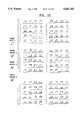
- FIGS. 16A, 16B, 16C.1-16C.4, and 16Dshow general byte maps of user control signals in the form of message packets.
- FIG. 17shows an example of access and authorization privileges in a large, enterprise-wide implementation.
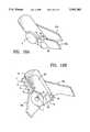
- FIGS. 18A and 18Bshow top perspective close-up views of a third embodiment of the user/computer interface device.
- FIGS. 19A and 19Bshow examples of the interface device operation.
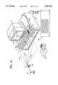
- FIG. 1Ashows a first embodiment of the present invention.
- a wireless battery-powered user/computer interface device 10transmits infrared user control signals 12 through signal transmission system 14, to a base/computer interface device 20, which is interconnected into a computer 30 via a cable 28.
- a hardwired signal transmission systemcan also be desirable where remote wirelessness is not needed or wanted by the computer user. Hardwired versions are less costly to manufacture than wireless versions.
- Signal generating circuitry(hardware and firmware) is implemented using a variety of well-known transceiver components, depending on the desired signal transmission system (e.g., infrared, radio, acoustic, hardwired, etc.).
- User control signals 12are transmitted from a user/computer interface device 10 in response to a computer user's manual operation of switches mounted thereupon (see FIG. 7A for switch detail). After the user presses one or more switches on device 10 to initiate user control signals, infrared signals 12 are generated by an infrared generator comprising one or more light emitting diodes (not shown) and exit the interface device 10 through infrared lens 8. Signals 12 propagate through free space and onto base/computer interface device 20. After detection by device 20, signals 12 are demodulated, de-encrypted, converted to computer-intelligible control signals and/or other control signals, and relayed into computer 30.
- Computer 30is connected to display terminal 18.
- Computer 30can also be optionally connected and/or networked with other interfaceable peripheral devices, one or more local area networks, or other centralized or distributed computers.
- display screen 19 of display terminal 18responds to user control signals 12 and other output/display signals from computer 30, such that desired effects of signals 12 can be executed and displayed on the display screen 19.
- Base/computer interface device 20includes an optional sonic receiver element 42 adapted to receive and transmit sonic signals from device 10.
- Device 20further includes lens 21 behind which stands one or more signal detectors, such as phototransistors, adapted to detect infrared user control signals 12 relayed from device 10, through wireless infrared signal transmission system 14.
- the base/computer interface device 20may also include an access key panel 26.
- Key panel 26is used to enter access and authorization codes so as to limit access to device 10.
- Key panel 26is a locking device, to control access to device 20, to ports 22 and 24, and to interface devices 10.
- Panel 26can include conventionally known locking hardware for restricting physical access to device 20 or device 10.
- Ports 22 and 24 on device 20are used for recharging of batteries in the interface device 10.
- Device 10includes female couplings 11a (as shown in FIG. 8), for manual coupling onto male couplings 11b to receive electrical charges for the rechargeable battery contained in device 10.
- Male couplings 11bare located within ports 22 and 24 in device 20.
- either a stand-alone AC/DC transformer (not shown) or the computer's serial portcan also be used for recharging the interface device 10.
- Display screen 19inherently includes preprogrammed cartesian (or other conventional) positioning areas to receive cursor coordinates provided by device 10.
- the ordinate axis 17b and the abscissa axis 17care shown.
- origin 17ais provided, through which a z-axis (not shown) is provided to assist in generation of three-dimensional displays.
- computer 30has a floppy or other storage disk drive 32 which is adapted to receive a floppy or other suitable diskette package 35 containing digitally encoded instructions 33 for interfacing the software drivers of the present invention with the operating system software of the computer 30.
- a keyboard 300is typically attached to the computer as a separate input device. However, keyboard use can be minimized or eliminated, for many important tasks, by use of the interface device 10.
- Fig. 1Bshows a first embodiment of device 10 attached to a computer user's forefinger.
- device 10can be attached to a support stand 70.
- the support stand 70is shown in FIG. 1D.
- Device 10is attached to an articulating support 72 of the support stand 70. Hooks 74a-74d as shown in FIG. 1D affix device 10 firmly onto support 72.
- Device 10can be moved freely about while attached onto support 72.
- Support 72plugs a concavity 76a onto ball joint 76b of support stand 70.
- Device 10could also be directly accommodated onto ball joint 76b without the articulating support 72 if an appropriate concavity 76a is included.
- Telescopic support stand members 70acan be used to allow extension and contraction of stand 70 to different heights, to suit user preferences.
- Support 72can also be used to carry other electronic components associated with device 10 operation, including additional means for creating user control signals, such as positionally activated switches.
- Support stand 70can be used in at least two basic ways: 1) with articulating support 72, or 2) without articulating support 72.
- device 10When device 10 is used attached to stand 72, the feature of travelling in more than one dimension at the same time is provided by the present invention.
- the computer userIn combination with a three-dimensional (virtual) display, the computer user can "travel" in two or three dimensions virtually simultaneously. This effect is achieved by liquid conductive switches or other position-activated switches (not shown) pointing in one virtual dimension (e.g., "x”) in combination with either one or two dimensions (e.g., y" and "z”) pointed to by device 10, using manually operable switches.
- virtual "three dimensional" travelcan be achieved, which can be helpful for many applications including CAX (i.e., CAD/CAM/CAE); gaming; robotics; education; virtual microscopy; multimedia; and other so-called “virtual reality” applications.
- CAXi.e., CAD/CAM/CAE
- gamingi.e., CAD/CAM/CAE
- gamingrobotics
- educationvirtual microscopy
- multimediamultimedia
- virtual realityvirtual reality
- Basic control elementsinclude wireless user/computer interface device 10, signal transmission system 14, base/computer interface device 20 and controlled computer 30.
- Signal transmission system 14 shownincludes bidirectionally operable communication channel 14a between device 10 and device 20; channel 14b within device 20, and channel 14c between device 20 and computer 30.
- FIG. 3is a block diagram of the basic functional modules of user/computer interface device 10, showing the main functional modules and the functional module interconnections. Typical hardware and electronic components are arranged to perform signal-generating, signal processing, signal-terminating, and signal-transmitting functions for user/computer interface device 10.
- Module 100represents the totality of any possible number of switch arrangements implemented on any given embodiment of user/computer interface device 10. Depending on the particular embodiment, these could correspond to manually operable switches shown as switches 2, 3, 1a, 1b, 1c, 1d, and 1e of FIG. 7A or to any other feasible alternative arrangement of switching components. Alternatively, a version of module 100 can be provided which reports switch states of internal switches, based upon the position positionally activated switches.
- FIG. 4illustrates switch hardware for four secondary thumbswitches 1a, 1b, 1c, 1d; for master control thumbswitch 2, for front switches 3a-3c, and for mode switch 1e.
- Switch states of switches 1a, 1b, 1c, 1d, 1e, 2, and 3are sensed by switch position sensing module 100 and sensed switch states are communicated to microcontroller 110.
- module 110represents a microprocessor or microcontroller for processing.
- the microcontroller 110detects the position and/or state of the control switches comprised in module 100.
- Module 110also serves to encode this information in accordance with predetermined parameters and modulation plans, using the information stored in personality ROM module 118 and ROM (or EEPROM) module 116.
- the result of this processis a composite signal which is then outputted from module 110 in an organized intermediate signal format and fed into module 114.
- module 110is implemented with the use of a microprocessor or microcontroller integrated circuit chip, whose specific functional and operational characteristics depend on the specific type of embodiment being implemented. Integrated circuits of this type are well-known in the art.
- the arrows between functional modules of user/computer interface device 10, shown in FIG. 3,represent individual or grouped conductive paths to relay signal intelligence and control signals between functional modules.
- Personality module 118is a ROM memory storage device, and module 116 is a ROM (or EEPROM) device. These devices store, in protected form, information which is used by module 110 to determine the encoding scheme and other information processing parameters.
- personality module 118contains application-specific, environment-oriented information and codes. The information and codes are used to determine the encoding and modulation scheme to be followed by module 110, in accordance with the specific application selected by the user.
- Module 118is implemented as an interchangeable ROM cartridge, that can be easily inserted and removed by the user (See FIG. 7A, modules 6a, 6b, 6c). Different ROM cartridges contain encoding and modulation plans and other information corresponding to different software applications. The user needs only to insert the ROM cartridge into device 10 which corresponds to the software application (i e., "personality operating environment") to be used.
- ROM (or EEPROM) module 116is implemented in device 10 for security-oriented applications.
- Module 116contains encryption security information, comprising one or more access by device 10 and authorization security tables for limiting access to any enterprise resource by: 1) one or more user(s); 2) one or more user/computer interface device(s); 3) one or more application(s); 4) one or more file(s); 5) one or more system(s); or 6) one or more network or signal transmission system communication channel(s), within the auspices of an overall, enterprise-wide access and authorization privileges plan.
- Access by users or devices to any given enterprise resourceis either granted or denied, based upon the security clearance of the user or device or based on any other command and control information defined and customized into the access and authorization privileges plan of the specific enterprise, as administered by an authorized systems administrator.
- Module 116is not designed to be installed, deinstalled, serviced, or updated by the user, but is controlled by the system or security administrator.
- modules 116 and 118are optional and depends on the particular application and environment for which device 10 is adapted. Furthermore, the specific integrated circuit chips used to implement functions of modules 116 and 118 is also dependent on the type of application, personality operating environment, or security plan being implemented.
- the output of module 110is a composite signal which is relayed into modulator/transceiver module 112.
- the signal path from module 110 to module 112passes through module 114, which acts as a kill switch. When switch 114 is open, the signal from module 110 cannot be input to module 112, and output signalling is disabled.
- the state of the signal path in kill switch 114is controlled by an external signal for disabling device 10.
- An external kill signalis generated and transmitted by base/computer interface device 20 or other authorized signal source.
- a kill signalwhen transmitted, is processed by transceiver module 112 of device 10, then relayed into kill switch 114.
- AND gate 114arequires two logical "1" inputs, in order to continue passing the signal from 110 to module 112.
- a kill signalsends a logical "0" input into AND gate 114a, opening the kill switch, and thereby removing the path into module 112.
- Module 112represents a modulator/transceiver device. This device is implemented as an electromagnetic wave modulator/transmitter (for infrared or radio waves), as an electronic transducer (for sonic or ultrasonic waves), or as a signal buffer/driver (for hard wired transmission).
- module 112uses the information conveyed to it from module 110 to modulate an electromagnetic carrier wave, either infrared or radio. The modulated signal is then radiated by means of a radiating device suitable to the frequency of the signal being radiated, or transmitted.
- module 112comprises an electronic amplifier and a sonic or ultrasonic transducer, depending on the specific means of transmission.
- Module 112produces appropriate signals 12 which propagate through free space and/or air and are received by base/computer interface device 20.
- the power of the radiated signal or intensity of the acoustic wavesis chosen such that the signal can be picked up by device 20, while the distance between device 10 and device 20 is within the intended operating range.
- Device 10also includes data input/output ports 4a and 4b adapted to import data from, or export data to, devices interfaceable with device 10.
- Power for user/computer device 10is provided through a battery 402, adaptable to be recharged via charge and control circuit 404 contained within base/computer device 20 (FIG. 6). Charging voltage passes through male plug 11b (FIG. 1A) which interconnects with female plug 11a of device 10, whenever device 10 is plugged into port 22.
- signals 12 transmitted to device 20are outputs from device 10. More specifically, signals 12 can comprise infrared, other electromagnetic radiation, optical and/or acoustic signals, depending on specific implementation requirements.
- infrared signals 12are received by, or transmitted out of, infrared transceiver module 210.
- sonic and/or optical transceiver devicescan be implemented to carry sonic and/or optical signals into and out of transceiver 210.
- Transceiver 210is connected to a microcontroller or microprocessor 212 to decode, or encode, signals 12. Demodulation occurs in a reverse manner to modulation, as is common practice.
- Information for encoding/decoding microcontroller 212is provided by memory element 214.
- Memory element 214can further comprise one or more ROM options as shown in FIG. 6.
- ROM 216includes a predetermined security table and related options.
- ROM 218includes a programmable security coding module option. Furthermore, a ROM or other suitable storage device 220 comprises means for modulation/demodulation of signals 12 in accordance with a preset modulation scheme implemented in user/computer interface device 10. Information in storage device 220 is used to interpret the signals 12 from device 10 according to any implemented personality environment. As a result, after incoming signals 12 are received by transceiver 210, they are supplied to the microcontroller 212 for subsequent decoding based upon information provided from memory 214 and memory 220. The decoded signals are then outputted from microcontroller 212 to a computer interface device comprised in module 225, such as a Universal, Asynchronous Receiver/Transmitter (UART) or similarly functional device.
- UARTUniversal, Asynchronous Receiver/Transmitter
- Module 225consists of any conventionally known computer interface device adapted to receive all original switch states generated in user/computer interface device 10, which are interpreted and stored in microcontroller 212, and to transfer those states to a computer 30.
- Another example of module 225is a shift register.
- each such personality operating environment(such as security access, CAD/CAM, etc.) are a plurality of modes selected by mode switch 1e each of which, in turn, controls the functions designated by selectable switches la-1d.
- one selected modemay be "input formatting", when a user wishes to designate various input formats for the controlled computer.
- the secondary control switches 1a-1ddesignate different "input formatting" switch functions, such as coloring, shading, hatching, providing standardized geometric figures.
- mode switch 1ecould involve an "output formatting" mode, with the color, style, and other "output formatting" functions being designated by the secondary control switches 1a-1d.
- the cable 28connects the output of base transceiver 20 to the input of an appropriate input port located on the reverse face of computer 30.
- the computer 30Upon receipt of the signal outputs from base transceiver 20, the computer 30 (via driver software) then interprets the signal 242. In response, the computer 30 invokes control over the display device 18 (FIG. 1A). The computer can also invoke control over any implemented controllable peripheral device via a direct, indirect, or virtual network connection.
- FIG. 7Aillustrates a detailed perspective view of a first version of a first embodiment of the user/computer interface device 10.
- device 10includes master control thumbswitch 2, which controls positioning of the computer display cursor.
- Thumbswitch 2can be very easily operated by the computer user's thumbtip, to control motion of the computer cursor in any direction (e.g., pressing locations 2a, 2b, 2c, and 2d respectively, runs the cursor up, right, down, and left) (see also FIG. 12).
- Coordinates 17a, 17b, 17c of FIG. 1A or other coordinates, (e.g., polar coordinates)can be manipulated.
- Three dimensional coordinates along a z-axisare also available through the switch 2 when the input device 10 is configured with an appropriate three-dimensional personality module and/or mode switch 1e selects three-dimensional operation.
- Device 10also contains four adjacent, thumb-operable, secondary control switch elements, 1a, 1b, 1c, and 1d. Each of the secondary switches respectively provides a different functional choice to the computer. In other words, switches 1a, 1b, 1c, and 1d functions can be analogous to the function keys on a computer keyboard. Other switches can be mounted upon the control surface 1. The other switches can vary in number, depending upon the version of device 10, the type of computer being interfaced, the applications being used, or computer environment being served.
- Mode switch 1eis a sliding switch, which slides from position 1e.1 to position 1e.8, as implemented in the user input device 10.
- the mode switch 1ehas significant operational implications in that it can be used to set the functional mode for the various functions represented by switches 1a-1d.
- each switch 1a-1dcan, in turn, change function eight times depending upon the setting of mode switch 1e.
- the changing of the mode switch setting 1ethus significantly changes the operating characteristics of switches 1a-1d and, in turn, the user input device 10.
- switch 1eis easily operable by the thumb.
- front switch 3On the front face of input device 10 is front switch 3, which can be considered a "click switch.” This switch operates in an analogous fashion to selection switches typically available on “mouse-type” input devices. As illustrated, the front switch 3 can toggle upward or downward and click “on” so that data upon which the cursor rests is entered into the computer 30. The capacity to perform these and other control actions allows the user to access a variety of control options in the computer 30. In yet other embodiments, the front switch 3 can, from its' center position, "click” directly inward one or more times to perform yet other "click” or multiple “click” functions.
- a lens 8 or any other appropriately implemented signal transmissive means for transmitting predetermined selected infrared or other signal type 12is provided.
- an acoustic signal emission port 41is illustrated.
- Interface device 10can implement an acoustic emission and detection option.
- the acoustic port 41in conjunction with acoustic signal generation means, can emit predetermined selected acoustic signals, when enabled.
- port 41requires a corresponding implementation of port 42 on base transceiver 20 of FIG. 1A.
- Port 42is an acoustic detector, and acoustic signals emitted from port 41 are detected therewith. Any known conventional acoustic transceiver hardware can be used.
- personality module 6ais shown loaded into input device 10.
- the personality module 6acan be easily removed from the personality module cabinet 6.
- the moduleconsists of, for example, a cartridge enclosed ROM having stored within it the various predetermined functions and data associated with the operating environment choice.
- different primary "operating personalities" of the computer user input device 10can be chosen by the computer user.
- Alternative personality modules 6b and 6ccan be selected by the computer user to implement different fundamental operating environments.
- Other personality modulescan also be used to replace installed personality module 6a simply by removing module 6a from cabinet 6, and inserting either module 6b, or module 6c, or any other module.
- Data port 4acan also be used for a variety of data inputs and outputs.
- a data input porte.g., to rewrite an EEPROM, for the purpose of updating security information
- input port 4aaffords much additional flexibility to device 10. It can be observed that 4a security updates, changing the access and authorization privileges of device 10 can help achieve objectives of the invention.
- data port 4acan be used to output device 10 stored data, which has been made accessible for export.
- Device 10does not require strapping to the user's hand, finger, wrist, etc., in order to operate properly. While strapping by means of a strap 40a and strap 40b is useful, strapping does not affect basic functions of device 10. Strap 40a and 40b can be padded (not shown) to provide greater user comfort. A padded lining contributes to the ergonomic design of device 10--allowing the user to comfortably wear device 10 for prolonged periods. Other strap designs or arrangements are contemplated. Other attachment means can attach device 10 to the human hand, wrist, finger, etc. For example, a ring or ring-type attachment means is shown in FIG. 9.
- straps 40a and 40bPrior to attaching device 10 to the left or right forefinger, straps 40a and 40b are affixed into the side of device 10 to which the user will attach his or her forefinger.
- Device 10has symmetrical, arcuate-shaped surfaces 99a and 99b which accommodate either left forefinger (99a) or right forefinger (99b) attachment with equal facility, to suit user preference or immediate needs.
- Strap 40a and 40bare attached to device 10 by attachment fittings.
- "snap-in" fittingscan be implemented on straps 40a and 40b, which can be snapped into complementary fitting receptacles or directly into concavities on device 10.
- FIG. 7Billustrates a second version of the first embodiment shown in FIG. 7A which contains similar elements to that of FIG.
- an alternative means for attaching the computer user input device 10 to the computer user's fingercan be a releasably secured ring 50. Ring-type attachment means may be desirable for some computer user preferences. Other strap attachment means can be provided, including leather. However, it appears that Velcro(R) straps with a padded lining best achieve the "illusion of weightlessness.”
- FIGS. 10A-10Cshow device 10 worn attached onto both of a user's forefingers.
- a keyboard 300can also be used jointly with device 10 for even greater flexibility in computer control.
- a second embodiment of a user/computer interface device 1100is shown attached onto a user's finger.
- the deviceis a simplified version of device 10 and includes only a thumbswitch 1102 and a thumbswitch selector switch 1104.
- FIG. 11Bis a top perspective close-up view of the second embodiment shown in FIG. 11A.
- the 1102 and 1104 switch arrangementoperates in a similar fashion to thumbswitch 2 and front switch 3 of the first preferred embodiment, shown in FIG. 7A.
- FIG. 12illustrates control of a cursor on the display screen.
- Display screen 19inherently includes a preprogrammed cartesian (or any other conventional or customized) positioning mechanism to receive cursor coordinates provided by computer 30, in accordance with user control signals 12, initiated and transmitted using device 10.
- origin 1217ais provided as a primary point of reference.
- FIG. 12shows a series of different, sequential examples of cursor movement events.
- the default position, 1217ais shown in the center of the screen.
- Screen 1204ais always the beginning screen of a cursor reinitialization and movement sequence.
- Default position 1217ais always presented in any basic cursor reinitialization control sequence, unless an alternative default position is customized by the user.
- Computer control eventssuch as cursor reinitialization, movement, select functions, and "click and drag” functions, are accomplished by using one of the secondary thumbswitches 1a-1d, in combination with master thumbswitch 2 and front switch 3.
- the specific functions assigned to the thumbswitchesdepends upon the mode switch 1e in combination with personality module and with any application software used in computer 30.
- Successive screensshow a progression of directional cursor moves using user control signals initiated by thumbswitch 2.
- thumbswitch 2For examples of "click and drag” action, using both thumbswitch 2 and front switch 3, see FIG. 20, which discusses usage of the present invention with "mapped keys” in a word processing application.
- directional pressure on switch 2moves the cursor up in the direction of direction 2a; cursor right, 2b; cursor down, 2c; and cursor left, 2d.
- Other directionsare implemented with appropriate switching circuitry and/or driver or other application software.
- FIGS. 13A and 13Bshow a typical security "operating personality" environment, wherein an "annunciator” and an “interrogator” are shown in a security-oriented dialogue.
- Each user/computer interface device 10is assigned a unique "device password.”
- each computer useris assigned a unique password.
- user passwords and device passwordsform a composite password which is designated the "annunciator" password.
- the composite passworditself, is a unique password specifically identifying both the computer user and interface device to the security system.
- Each layer of one or more layers in a security system logicis designated an "interrogator.” Both user and device passwords must be authorized to gain or continue computer access, i.e. to any enterprise resource, or to complete a transaction. If either password is not authorized to gain or continue access to complete the requested transaction, then the attempted transaction is determined “illegal” by the interrogator security logic. After any transaction is deemed “illegal,” alarm features are activated, including activation of the kill switch 114 of device 10.
- interrogator functionsare started at step 1302.
- the interrogatorbegins a wait state loop at step 1304, listening for any annunciator signal.
- the interrogatoris testing for the annunciator signal receipt from any annunciator desiring access. Until the answer is "yes,” the system loops, listening for input from any annunciator.
- Annunciator signal generation capabilityis active in device 10 at step 1308, given that device 10 contains a security personality module or other means to be responsive to manual input of a computer user's password.
- the userinputs a password into device 10, and the annunciator functions are enabled.
- the correct user passwordenables the device 10 for transmission of an annunciator signal.
- the annunciator signalis transmitted from device 10 to the cognizant interrogator.
- An interrogatormay be located in base/computer transceiver 20 which is interconnected into the individual computer (or other access point) being accessed. Alternatively, interrogators may be located at any access points to any enterprise resource.
- step 1306the process for validating and identifying the annunciator signal and identifying the user begins.
- the interrogatordetermines if annunciator input device 10 transmitted a composite ID along with the annunciator signal. If a complete composite ID is received by step 1315, it is authenticated, beginning at step 1332.
- the interrogatorgenerates a "Who Are You” inquiry, which is transmitted at step 1318 to the annunciating device.
- the annunciatorprocesses the "Who Are You" identification request at beginning step 1322. If a complete composite ID was not sent originally, and a "Who Are You” signal is not received, then the annunciator signal is regenerated 1310 and transmitted (or retransmitted if it was missed) at step 1312.
- the annunciator (device 10) authentication/ID response to the interrogator "Who Are You” inquirybegins at step 1322, after receipt of the "Who Are You” signal.
- the authentication/IDis fetched from input device 10's memory at step 1324.
- the interrogatorAfter the ID has been fetched from memory, it is transmitted at step 1325 to the interrogator, which is waiting for this complete signal at step 1326. If the signal is not received at step 1326, at step 1328 the interrogator loops back N number of times to reinitiate the authentication/identification process. Once the N number of loops have been exceeded, however, then an alarm routing is called at step 1330.
- the interrogatortransmits the received signal to the security memory for comparison against the authentication/ID database (module 216 of FIG. 6).
- the received authentication/IDis compared in the security database and an ID status message is then produced at step 1338.
- the authentication/ID received by the interrogatoris determined to be either valid or invalid.
- step 1346the access enabling process is entered. Two events then occur. First, an annunciator enable signal is generated at step 1348 and the interrogator transmits the annunciator enable signal at step 1352 to the annunciator. Second, the transaction monitor routine is initiated at step 1347 to ensure that each successive attempted transaction is legal. On the annunciator side, the initial enable process is initiated at step 1354 with receipt of the interrogator-initiated annunciator enable signal. Before any enablement occurs, however, the system tests at step 1356 to determine whether more work is being done.
- annunciator enablementis no longer required--the annunciator will end the session with a logoff transaction.
- the device annunciatorwill automatically disable itself (unless other arrangement is made) and it can only be re-enabled by repeating the entire security procedure by an authorized user and device.
- step 1344If the ID is invalid, a record of the ID and the attempted transaction is made in the security memory 1336 and the alarm process is initiated, step 1344.
- interrogator functionscan be configured by the system administrator or security administrator to be repetitive--i.e., the interrogator can be set to periodically request the annunciator/ID during the progress of any access session being made by the user/annunciator, in accordance with a policy of the computer institution or device being accessed.
- Routine 1350In the interrogator, the "continue annunciator enable? "routine is continuously occurring in the background at step 1350. With this routine, initiated at step 1347, the security system is continuously testing to see if each specific annunciator transaction being attempted should continue to be enabled or permitted, within the context of the session. Routine 1350 can disable annunciator operation or disable any transaction at any point that the interface device annunciator steps beyond its' access and authorization privileges.
- the requested transaction and the IDsare recorded by the interrogator for security monitoring at step 1344.
- the interrogatordetermines whether to disable the device, starting at step 1380.
- the ID and transaction informationis again compared with the authorization and access privileges plan in the ROM 1336. If the device is to be disabled, step 1390, the kill signal is transmitted at step 1392. Otherwise, a message as to the reasons that access is being denied is presented to the user, step 1396, or the device is enabled, step 1346.
- one or more individually authorized user/annunciator(s)are granted access to enterprise resources (PCs, networks, applications, etc.) by any "interrogator" at one or more levels--i.e., the total security system logic contained in input device(s), and/or base transceiver(s), and/or LAN network server(s) and/or centralized computer(s) and/or mainframe(s)--which interrogates any annunciator seeking access, to verify that both the user/annunciator and the device/annunciator are authorized access, and what level or levels of access are authorized.
- the security module contained in base transceiver 20 which interacts with input device 10is the interrogator. Any annunciator--i.e., any input device 10--operated by any user desiring access--any authorized user/annunciator--transmits an access request signal to the interrogator.
- access controlbegins by initiating enterprise-wide security system interrogator functions--this is typically done by the system administrator or security administrator. This occurs in similar fashion to initiating a local area network server and its' client devices (e.g., as in Novell, 3COM, or other LANs). This can also occur similar to initiating other types of centralized or distributed networks (e.g., SNA); teleprocessing systems (VTAM, TCAM, etc.); transactions processing applications (e.g., CICS) or other operating system, application, or system access method.
- SNAcentralized or distributed networks
- VTAMteleprocessing systems
- TCAMteleprocessing systems
- CICStransactions processing applications
- the present inventionadds the unique features of 1) an access-seeking user/annunciator which must access user/computer interface device 10 with a password; and 2) after a satisfactory user access, device 10 then transmits its' own composite annunciation signal; and 3) distributed or centralized security logic then authenticates that specific input device 10's annunciation signal and allows only access authorized to that specific device 10 and that specific user.
- groups of computersare shown arrayed within a computing institution or enterprise.
- One or more properly authorized users(using one or more properly authorized devices 101-110 of the type of device 10 of FIG. 1A) in the local area network (LAN) shown in FIG. 14 can gain access to any computer on the LAN implementing the present invention, under the organizational auspices of an all-encompassing, enterprise-wide, security-oriented access and authorization privileges plan. Such a plan is shown below in Table A
- the access and authorization privileges aspects of the present inventionare highly flexible, and can be implemented in a number of ways, to suit virtually all user needs.
- a system administratoronly needs to define users, define devices, define one or more levels of access, and define enterprise resources in order to develop an access and authorization privileges plan.
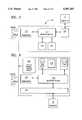
- FIG. 15An extended enterprise-wide computer control system is shown in FIG. 15.
- Six LANscomprised of twenty computers each are shown. All twenty computers "local" to each LAN are controlled by ten "local" user input devices associated with each respective LAN.
- FIG. 15thus illustrates an implementation of the present invention which has subdivided an enterprise-wide group of one hundred twenty computers into six LAN operating groups which each operate as separate LANs. Separately, shown to the left of the 120 computers, are four "grand master" input devices, labelled I, II, III, and IV. Each of these grand master input devices can access all 120 of the enterprise's computers. By virtue of their "grand master" status, each can operate on all six LANs shown.
- the 120 computer, 6 LAN enterprise of FIG. 15,has defined in its' access and authorization privileges plan, such that only four grandmaster (I, II, III, and IV) input devices need to be authorized access to all 120 computers. While each LANs' group of ten input devices could be implemented to access one or more other LANs' computers, in this example, only "grandmasters" access all six LAN groups' computers.
- Access and authorization privileges planscan vary from simple network definitions, to advanced, meshed, layered network definitions.
- Advanced access and authorization planscan include definitions which control access to complex networks with inter-LAN gateways, access to other centralized or distributed computers such as mainframes, or any other enterprise resource definitions suitable to the enterprise's needs.
- FIGS. 16A, 16B, and 16C.1-16C.4each show a table illustrating examples from different classes of user control signals. These signals are represented in message packets.
- Device 10using the personality modules, can transmit a plurality of distinct user control signals based upon different encoding sequences. Control signals are transmitted as bursts of coded pulses comprising one or more message packets. Each message packet includes a plurality of fields of encoded characters. The type of control signal determines the packet fields and organization. The format of the message packet is determined by the selected personality module.
- FIG. 16Aillustrates the message packet format for computer control, which includes a high-level, security-oriented ROM personality module 118 (FIG. 3) or for use of the security EEPROM 116 (FIG. 3).
- Field 1is a flag indicating the start of the message packet.
- Fields 2-4provide ID information designating the device and the user. This information is used to determine proper authorization privileges in the annunciator/interrogator dialog. (See FIG. 13)
- the command/control informationis contained in field 5. This information relates to the setting of the switches on device 10 and provides the actual computer control signals. These fields are shown Below in Table B
- a stop flagindicates the end of the packet.
- Security functionscan be included with other processing information. If security is implemented, the ID information fields are included at the beginning of each message packet. The remaining function information is contained in the succeeding fields.
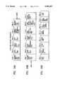
- FIG. 16Billustrates a message packet for a CAX personality module.
- Fields 1 and 2start the message and relate ID information similar to the security-oriented packet of FIG. 16A.
- information defining the personality environmentcan be included in the beginning fields.
- Field 3contains design mode information, such as a manufacturing or electrical design mode. For example, the design mode can be determined by the setting of mode switch 1e.
- Fields 4-6contain the basic command function data, such as "insert" "delete” and "create a point.”These fields are shown below in Table C
- the command function data or user control signalswould generally be designated by pressing switches 1a-1d. Some functions are defined in relation to the previous function performed. Therefore, fields 5 and 6 are used to provide the prior function state and change. Any additional information or control data required for a specific function is included in field 7. An end message flag would also be included for this packet.
- FIGS. 16C.1-16C.4illustrates other user control signals.
- FIG. 16C.2shows functions used to initiate processing on a system. After successfully accessing a specific computer or other resource, cursor movement and an example format for cursor control are illustrated in FIG. 16C.2 and Table H below.
- the modei.e. the setting for switch 1e
- the modeis needed, and is included in field 5.
- the indicated key meaningis included in field 7 (FIGS. 16C.3 and 16C.4) and Tables F and G below. The meaning is also affected by the mode referenced in field 5.
- the base/computer interface device 20determines the type of packet and the relevant information contained in the packet. Appropriate control signals are generated and transmitted to the computer 30 to execute the functions.
- FIG. 16D and Table H belowillustrates a message packet for a control signal from the base/computer device 20 to the user/computer interface device 10.
- the bidirectionality of the signal transmission systemallows for signals both to and from the base/computer interface device 20.
- the packet fieldsare used to transfer information for activating the kill switch due to improper access requests.
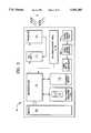
- FIG. 17shows a table, indicating an example of the general organization of a predetermined access and authorization privileges plan, developed for the purpose of safeguarding access to confidential data and restricting access to enterprise resources, as needed to satisfy a wide range of user requirements.
- FIG. 17shows an example of one possible enterprise-wide access and authorization privileges plan.
- Enterprise resources 800comprise resource categories R1 through RN.
- R1 resources 810comprise six separate LANs--LAN100 through LAN600, as illustrated in FIG. 15.
- R2 resources 820comprise mainframe resources accessible in enterprise-wide network 800.
- R3 resources 830comprise network resources, including communications channels used within enterprise resources 800.
- R4 resources 840comprise application resources which can include teleprocessing monitors, database applications, spreadsheet applications, network applications, etc.
- R5 resources 850are not used, in this example, but can be made available at a future time.
- R6 resources 860comprise the set of all user/computer interface devices 0001 through 0060 and grandmaster devices I, II, III and IV.
- each authorized computer userusing enterprise resources 800, is assigned an unique password identification.
- a user passwordwill allow the user to access any enterprise resource for which he/she is authorized access, to the extent that the user/device composite is allowed.
- usersare assigned passwords for the purpose of accessing at least one user/computer interface device; and, after accessing device 10, for accessing one or more specific computers, applications, or any other enterprise resource, to which the user is authorized access.
- accessing device 10for accessing one or more specific computers, applications, or any other enterprise resource, to which the user is authorized access.
- computer usersdo not access the computer directly.
- Usersaccess user/computer interface devices, which in turn access computers using a combination user password and a device password.
- An access and authorization plancan be implemented in the operating system software; applications software; ROMs; and/or EEPROMs, depending on user needs and implementing means chosen.
- the access and authorization informationis stored in the electrically-erasable programmable read-only memory (“EEPROM") 116 (FIG. 3) of device 10.
- EEPROMelectrically-erasable programmable read-only memory
- the informationcan include unique identifying data for the device or user for use in security-oriented applications.
- an EEPROM programmer devicein conjunction with specialized data input ports 4a and/or 4b, can be used to repeatedly change or update EEPROMs.
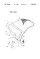
- FIG. 18Ashows a basic version of a third embodiment of device 10.
- FIG. 18Bshows an advanced version. Both versions can be attached to the left or right forefinger.
- the third embodimentis especially adapted for computer input and control needs of users with mobility impairments or other serious physical handicaps.
- the embodiment shown in FIGS. 18A and 18Bare specifically adapted for attachment to the user's right forefinger.
- Devices of the third embodimentare explicitly designed to serve the market niche often referred to as the "assistive technologies.”
- One arcuate-shaped surface 89is available to accommodate the left or right forefinger. This is in contrast to the two arcuate-shaped surfaces 99a and 99b of the first embodiment (FIG. 7A).
- Straps 40a and 40boperate to encircle the proximal phalange of the forefinger and affix it into arcuate-shaped surface 89.
- the third embodimentshows a different placement of personality module cabinet 6, in FIG. 18B.
- interchangeable ROM cartridges(such as 6a, 6b, and 6c of FIG. 7) are used therein.
- FIG. 19Ashows a "mapped keys" application for use in word processing in connection with the interface device of the present invention.
- Device 10can be used to move the cursor over one or more "expanding maps" of keyboard layouts. The user can then select "mapped keys” to spell out words without need of a keyboard.
- the useris presented with successive expanding screens of letters and numbers in the format of the keyboard layout of the user's choice. An area of the displayed keyboard is selected according to the direction of cursor movement. Upon arriving at the chosen character, the user selects it. This seek-and-select procedure is repeated, to select a series of characters in succession until the desired word is spelled out.
- the screenscan display a standard QWERTY keyboard layout or any customized key layout can be used, to suit user preferences.
- successive screens 1901a, 1901b, and 1901cshow expanding screens "zooming-in" on an area of a displayed keyboard layout, according to the direction of cursor movement.
- the userselects it, as in screen 1901d, which shows selection of the letter "M”.
- Screens 1902a, 1902b, and 1902cshow selection of the letter "0".
- a "Morse code wheel”can be operated in a manner similar to the word processing sequence.
- the "wheel” screenis comprised of sectors, wherein each sector represents one or more dots or dashes.
- To encode a series of charactersthe user "seeks-and selects" different dot or dash patterns, by moving the cursor from one sector to another to encode one or more alphanumeric characters. The user continues to select character encoding sequences to spell words. Spaces between words are selected, as needed. When the user reaches the end of their desired message he/she selects the "xmit" sector, which automatically routes the encoded message train to a preselected destination.
- transceiverhas been used to illustrate that according to the present invention, both a “transmitter” and a “receiver” are provided together in close proximity for two-way, or “duplex” operation (i.e., base transceiver 20 has both a transmitter and a receiver contained within the same electronic enclosure, as both transmission and reception of signals are provided therein).
- base transceiver 20has both a transmitter and a receiver contained within the same electronic enclosure, as both transmission and reception of signals are provided therein.
- the user input device 10can also be designated as a “transceiver” given its duplex communications capability shown by “kill circuit” and other "receiver” functions.
Landscapes
- Engineering & Computer Science (AREA)
- Theoretical Computer Science (AREA)
- General Engineering & Computer Science (AREA)
- Human Computer Interaction (AREA)
- Physics & Mathematics (AREA)
- General Physics & Mathematics (AREA)
- Health & Medical Sciences (AREA)
- Computer Hardware Design (AREA)
- Biomedical Technology (AREA)
- Software Systems (AREA)
- Computer Security & Cryptography (AREA)
- Heart & Thoracic Surgery (AREA)
- Vascular Medicine (AREA)
- Life Sciences & Earth Sciences (AREA)
- Animal Behavior & Ethology (AREA)
- General Health & Medical Sciences (AREA)
- Public Health (AREA)
- Veterinary Medicine (AREA)
- Position Input By Displaying (AREA)
- Input From Keyboards Or The Like (AREA)
Abstract
Description
TABLE A __________________________________________________________________________CUID # AUTH. COMPUTER(S) AUTH. LEVEL(S) USER NAME __________________________________________________________________________101 ALL ALL (I-V) SYSTEM ADMIN/GRAND MASTER 102 "2, 3, 4, 5, 6" I,II DATA ENTRY 103 "2, 3, 4, 5, 6" I,II DATA ENTRY 104 "2, 3, 4, 5, 6" I, II, IIIDATA ENTRY SUPERVISOR 105 "9, 10, 11" ALLENGINEERING 106 "9, 10, 11" ALLENGINEERING 107 "9, 10, 11, 12, 13" ALLENGINEERING SUPERVISOR 108 ALL I,II DATA COMMUNICATIONS 109 "13, 14, 15, 16" I, II,III PERSONNEL 110 "17, 18, 19, 20" I, II, III ADMINISTRATION __________________________________________________________________________
TABLE B __________________________________________________________________________FIELD: __________________________________________________________________________1 WAKE-UP DETECTION CIRCUITRY / MESSAGE FOLLOWS / 2 UNIQUE DEMCE ID & TIME-STAMP &PRIVILEGES 3 UNIQUE DEVICE GROUP ID & TIME-STAMP &PRIVILEGES 4 UNIQUE USER ID & TIME-STAMP &PRIVILEGES 5 USER COMMAND/CONTROL SIGNAL 2D 1.01 1.02 2D.1 CONTROL/SIGNAL MESSAGE PACKETS . . . __________________________________________________________________________
TABLE C __________________________________________________________________________FIELD: __________________________________________________________________________1 WAKE-UP DETECTION CIRCUITRY / MESSAGE FOLLOWS / 2 USER'SUNIQUE ID 3 DESIGN MODE MANUFACTURING DESIGN ELECTRICAL ENGINEERING DESIGN ARCHITECTURAL DESIGN MUSICAL NOTATION ETC. 4 BASIC ACTIVITY INSERT DELETE __________________________________________________________________________
TABLE D ______________________________________ 1.01 ANNUNCIATE 1.05 CONNECT 1.09 1.02 AUTHORIZATION 1.06 BOOT (WARM) 1.10 1.03 ENERGIZE 1.07 INSERT 1.11 1.04 DE-ENERGIZE 1.08 DELETE 1.12 . . . ______________________________________
TABLE E ______________________________________ 2.01 UP 2.05 RESERVED 2.09 CLICK 2.02 RIGHT 2.06 RESERVED 2.10 DOUBLE CLICK 2.03 DOWN 2.07 RESERVED 2.11 TRIPLE CLICK 2.04 LEFT 2.08 . . . RESERVED ______________________________________
TABLE F ______________________________________ 3.01 CLICK 3.04 DRAG 3.07 3.02 DOUBLE CLICK 3.05 CUT & PASTE 3.08 . . . 3.03 TRIPLE CLICK 3.06 MOVE ______________________________________
TABLE G __________________________________________________________________________4.01 EXECUTE 1a FOR SELECTED MODE SWITCH SETTING 4.02 EXECUTE 1b FOR SELECTED MODE SWITCH SETTING __________________________________________________________________________
__________________________________________________________________________FIELD: __________________________________________________________________________WAKE UP DETECTION CIRCUITRY/SIGNAL FOLLOWS 1: INTERROGATOR ID FIELD (SIGNAL-ORIGINATING INTERROGATOR) 2: TARGET DEVICE ID FIELD (DEVICE ID BEING "KILLED") 3: EXCEPTION CODE FIELD (REASON WHY KILL SIGNAL WAS TRIGGERED) 4: ALARM PRIORITY CODE (IF APPLICABLE) 5: KILL SIGNAL AUTHORIZATION SER. NO. ASSIGNED BY HIGHEST AUTHORITY INTERROGATOR (WHEN MULTIPLE LAYERS OF SECURITY APPLY) OR BY KILL SIGNAL ORIGINATING INTERROGATOR WHEN ONLY ONE LAYER OF SECURITY APPLIED 6: KILL SIGNAL, WITH TIME STAMP 7: STOP FLAG, INCLUDING "WRU", TO ENSURE KILL SIGNAL WAS RECEIVED (IF DEVICE BEING KILLED RESPONDS, THIS TRIGGERS SENDING OF ANOTHER KILL SIGNAL, UNTIL "NO RESPONSE") __________________________________________________________________________
Claims (41)
Priority Applications (4)
| Application Number | Priority Date | Filing Date | Title |
|---|---|---|---|
| US07/879,374US5481265A (en) | 1989-11-22 | 1992-05-07 | Ergonomic customizeable user/computer interface devices |
| US08/581,429US5729220A (en) | 1989-11-22 | 1995-12-29 | Ergonomic customizable user/computer interface device |
| US09/037,061US6201484B1 (en) | 1989-11-22 | 1998-03-09 | Ergonomic customizeable user/computer interface device |
| US09/732,112US6441770B2 (en) | 1989-11-22 | 2000-12-07 | Ergonomic customizeable user/computer interface devices |
Applications Claiming Priority (2)
| Application Number | Priority Date | Filing Date | Title |
|---|---|---|---|
| US44077189A | 1989-11-22 | 1989-11-22 | |
| US07/879,374US5481265A (en) | 1989-11-22 | 1992-05-07 | Ergonomic customizeable user/computer interface devices |
Related Parent Applications (1)
| Application Number | Title | Priority Date | Filing Date |
|---|---|---|---|
| US44077189AContinuation-In-Part | 1989-11-22 | 1989-11-22 |
Related Child Applications (1)
| Application Number | Title | Priority Date | Filing Date |
|---|---|---|---|
| US08/581,429ContinuationUS5729220A (en) | 1989-11-22 | 1995-12-29 | Ergonomic customizable user/computer interface device |
Publications (1)
| Publication Number | Publication Date |
|---|---|
| US5481265Atrue US5481265A (en) | 1996-01-02 |
Family
ID=23750112
Family Applications (4)
| Application Number | Title | Priority Date | Filing Date |
|---|---|---|---|
| US07/879,374Expired - LifetimeUS5481265A (en) | 1989-11-22 | 1992-05-07 | Ergonomic customizeable user/computer interface devices |
| US08/581,429Expired - LifetimeUS5729220A (en) | 1989-11-22 | 1995-12-29 | Ergonomic customizable user/computer interface device |
| US09/037,061Expired - LifetimeUS6201484B1 (en) | 1989-11-22 | 1998-03-09 | Ergonomic customizeable user/computer interface device |
| US09/732,112Expired - Fee RelatedUS6441770B2 (en) | 1989-11-22 | 2000-12-07 | Ergonomic customizeable user/computer interface devices |
Family Applications After (3)
| Application Number | Title | Priority Date | Filing Date |
|---|---|---|---|
| US08/581,429Expired - LifetimeUS5729220A (en) | 1989-11-22 | 1995-12-29 | Ergonomic customizable user/computer interface device |
| US09/037,061Expired - LifetimeUS6201484B1 (en) | 1989-11-22 | 1998-03-09 | Ergonomic customizeable user/computer interface device |
| US09/732,112Expired - Fee RelatedUS6441770B2 (en) | 1989-11-22 | 2000-12-07 | Ergonomic customizeable user/computer interface devices |
Country Status (5)
| Country | Link |
|---|---|
| US (4) | US5481265A (en) |
| EP (1) | EP0500794A4 (en) |
| JP (1) | JPH05502130A (en) |
| AU (1) | AU7788191A (en) |
| WO (1) | WO1991007826A1 (en) |
Cited By (179)
| Publication number | Priority date | Publication date | Assignee | Title |
|---|---|---|---|---|
| WO1996034333A1 (en)* | 1995-04-26 | 1996-10-31 | Interval Research Corporation | Context sensitive universal interface device |
| US5638092A (en)* | 1994-12-20 | 1997-06-10 | Eng; Tommy K. | Cursor control system |
| WO1997027674A1 (en)* | 1996-01-26 | 1997-07-31 | Harrison Shelley | Key palette |
| WO1997033395A1 (en)* | 1996-03-06 | 1997-09-12 | Bbn Corporation | Personal data network |
| US5801918A (en)* | 1996-07-12 | 1998-09-01 | Hand Held Products, Inc. | Ergonomic housing for a micro computer |
| US5812371A (en)* | 1995-07-25 | 1998-09-22 | Compal Electronics, Inc. | Orientation-adjustable infrared transceiver used in a notebook type computer |
| US5815679A (en)* | 1996-07-23 | 1998-09-29 | Primax Electronics, Ltd. | Interface device for controlling computer peripherals |
| EP0789320A3 (en)* | 1996-02-09 | 1998-10-21 | Pegasus Technologies Ltd. | Computer mouse and holder |
| USD400872S (en) | 1997-10-27 | 1998-11-10 | Hand Held Products, Inc. | Contoured housing |
| US5854624A (en)* | 1996-09-12 | 1998-12-29 | Innovative Device Technologies, Inc. | Pocket-sized user interface for internet browser terminals and the like |
| US5920306A (en)* | 1994-03-11 | 1999-07-06 | Elonex P.L.C. | Method and apparatus for a broadcast pointer system |
| US5943042A (en)* | 1994-10-07 | 1999-08-24 | International Business Machines Corporation | Control method and system for objects on a computer |
| USD413360S (en) | 1997-08-26 | 1999-08-31 | Tim Smith | Controller for a game machine |
| US6157368A (en)* | 1994-09-28 | 2000-12-05 | Faeger; Jan G. | Control equipment with a movable control member |
| US6160540A (en)* | 1998-01-12 | 2000-12-12 | Xerox Company | Zoomorphic computer user interface |
| KR20010004087A (en)* | 1999-06-28 | 2001-01-15 | 박준일 | Ring type touch pad |
| EP1079325A1 (en)* | 1999-08-25 | 2001-02-28 | Swatch Ag | Watch having a non-contact computer cursor controller |
| US6201484B1 (en)* | 1989-11-22 | 2001-03-13 | Transforming Technologies, Llc | Ergonomic customizeable user/computer interface device |
| USD439898S1 (en) | 1996-03-18 | 2001-04-03 | Hand Held Products, Inc. | Contoured housing |
| US6237879B1 (en) | 1999-09-10 | 2001-05-29 | Michael Budge | Ergonomic comfort pads for portable or notebook computers |
| US6297808B1 (en)* | 1997-11-21 | 2001-10-02 | Tai-Her Yang | Controller device including at least one finger hole, a trackball, and a display screen |
| US6300939B1 (en)* | 1997-10-23 | 2001-10-09 | Nokia Mobile Phones Ltd. | Input device |
| RU2175143C1 (en)* | 2000-04-04 | 2001-10-20 | Свириденко Андрей Владимирович | Remote control technique |
| US20010033267A1 (en)* | 1998-09-02 | 2001-10-25 | Darren Kim | Notebook computer with detachable infrared multi-mode input device |
| US6344845B1 (en)* | 1994-07-29 | 2002-02-05 | Sony Corporation | Position inputting device and video signal processing apparatus |
| DE10040812A1 (en)* | 2000-08-21 | 2002-03-14 | Infineon Technologies Ag | Wrist-watch-type mouse especially for notebook or laptop computer, includes ring with sensors connected to interface in armband by cables |
| US20020069067A1 (en)* | 2000-10-25 | 2002-06-06 | Klinefelter Robert Glenn | System, method, and apparatus for providing interpretive communication on a network |
| WO2002054215A1 (en)* | 2001-01-03 | 2002-07-11 | Digityper Ab | A portable device for inputting control signals to a peripheral unit, and use of such a device |
| US20020091843A1 (en)* | 1999-12-21 | 2002-07-11 | Vaid Rahul R. | Wireless network adapter |
| DE10101839A1 (en)* | 2001-01-17 | 2002-07-18 | Dirk Bertram | Device for controlling position indicator on visual display is worn on operator's finger, has control element positioned to prevent unintentional operation, is protected against loss by holder |
| DE10103888A1 (en)* | 2001-01-30 | 2002-08-14 | Paul Bellendorf | control device |
| US20020130692A1 (en)* | 1999-06-28 | 2002-09-19 | Broadcom Corporation | Current-controlled CMOS logic family |
| US6462729B2 (en)* | 1992-06-30 | 2002-10-08 | Sony Corporation | Search and display apparatus |
| US6462732B2 (en)* | 1999-07-28 | 2002-10-08 | Michael Mehr | Hand un-inhibiting cursor control device |
| US20020167422A1 (en)* | 2001-04-27 | 2002-11-14 | Jacques Andre | Device for controlling a three-dimensional movement |
| US20030025721A1 (en)* | 2001-08-06 | 2003-02-06 | Joshua Clapper | Hand mounted ultrasonic position determining device and system |
| US20030028688A1 (en)* | 2001-04-10 | 2003-02-06 | Logitech Europe S.A. | Hybrid presentation controller and computer input device |
| US20030030542A1 (en)* | 2001-08-10 | 2003-02-13 | Von Hoffmann Gerard | PDA security system |
| US20030038783A1 (en)* | 2001-08-27 | 2003-02-27 | Baughman Pamela M. | Wearable ergonomic computer mouse |
| US20030048174A1 (en)* | 2001-09-11 | 2003-03-13 | Alcatel, Societe Anonyme | Electronic device capable of wirelessly transmitting a password that can be used to unlock/lock a password protected electronic device |
| US20030067337A1 (en)* | 1999-06-28 | 2003-04-10 | Broadcom Corporation | Current-controlled CMOS circuit using higher voltage supply in low voltage CMOS process |
| US6552714B1 (en)* | 2000-06-30 | 2003-04-22 | Lyle A. Vust | Portable pointing device |
| US20030076357A1 (en)* | 1998-10-27 | 2003-04-24 | Glaser Lawrence F. | Computer pointing device having theme identification means |
| USD473872S1 (en) | 1996-03-18 | 2003-04-29 | Hand Held Products, Inc. | Contoured housing |
| USD476330S1 (en) | 1996-03-18 | 2003-06-24 | Hand Held Products, Inc. | Contoured housing |
| US20030122603A1 (en)* | 2000-02-24 | 2003-07-03 | Broadcom Corporation | Current-controlled CMOS circuits with inductive broadbanding |
| US20030142065A1 (en)* | 2002-01-28 | 2003-07-31 | Kourosh Pahlavan | Ring pointer device with inertial sensors |
| US20030148249A1 (en)* | 1995-12-29 | 2003-08-07 | Marcus Brian I. | Educational electronic toy for children |
| US20030160762A1 (en)* | 2002-02-22 | 2003-08-28 | Ho-Lung Lu | Rechargeable wireless mouse |
| US6618039B1 (en)* | 1996-09-12 | 2003-09-09 | Gerry R. Grant | Pocket-sized user interface for internet browser terminals and the like |
| US6624804B2 (en) | 1998-04-06 | 2003-09-23 | Ethertouch Limited Of Brumby House | Positioning a cursor on the display screen of a computer |
| US6624824B1 (en)* | 1996-04-30 | 2003-09-23 | Sun Microsystems, Inc. | Tilt-scrolling on the sunpad |
| US20030206393A1 (en)* | 2002-05-06 | 2003-11-06 | Murray William P. | TV mute finger ring |
| US20030209604A1 (en)* | 1996-01-26 | 2003-11-13 | Harrison Shelton E. | Wearable computing system, method and device |
| WO2003100717A1 (en)* | 2002-05-28 | 2003-12-04 | Digityper Ab | A device for inputting control signals to a peripheral unit and a combination including such a device |
| US6664949B1 (en)* | 1999-11-05 | 2003-12-16 | International Business Machines Corporation | Interoperable/heterogeneous environment keyboard |
| US20040012559A1 (en)* | 2002-07-17 | 2004-01-22 | Kanazawa University | Input device |
| US20040018851A1 (en)* | 1990-01-18 | 2004-01-29 | Koenck Steven E. | Modular, portable data processing terminal for use in a radio frequency communication network |
| US20040017824A1 (en)* | 1989-04-14 | 2004-01-29 | Koenck Steven E. | Modular, portable data processing terminal for use in a radio frequency communication network |
| US20040044627A1 (en)* | 1999-11-30 | 2004-03-04 | Russell David C. | Methods, systems and apparatuses for secure transactions |
| US20040059463A1 (en)* | 2002-06-24 | 2004-03-25 | Scriptpro Llc | Active control center for use with an automatic dispensing system for prescriptions and the like |
| US20040056717A1 (en)* | 2001-10-25 | 2004-03-25 | Broadcom Corporation | Current-controlled CMOS wideband data amplifier circuits |
| US6720948B2 (en)* | 2001-10-11 | 2004-04-13 | International Business Machines Corporation | Method, program, and system for communicating between a pointing device and a host computer |
| US20040078792A1 (en)* | 2002-10-21 | 2004-04-22 | Microsoft Corporation | System and method for selectively deactivating auto-deploy functionality of a software input panel |
| USD492681S1 (en) | 1996-03-18 | 2004-07-06 | Hand Held Products, Inc. | Contoured housing |
| WO2002088918A3 (en)* | 2001-05-02 | 2004-07-08 | Midwest Research Inst | Multi-functional ergonomic interface |
| US20040134049A1 (en)* | 2002-07-11 | 2004-07-15 | Hans-Jurgen Schreiner | Insulation for piezoceramic multilayer actors |
| US6768483B1 (en) | 1997-11-13 | 2004-07-27 | Prosisa Overseas, Inc. | System and method of providing restrained, streamlined access to a computerized information source |
| US6781570B1 (en)* | 2000-11-09 | 2004-08-24 | Logitech Europe S.A. | Wireless optical input device |
| US20040207040A1 (en)* | 2001-05-17 | 2004-10-21 | Broadcom Corporation | Layout technique for C3MOS inductive broadbanding |
| US20040217777A1 (en)* | 1999-06-28 | 2004-11-04 | Armond Hairapetian | Universal single-ended parallel bus |
| US20040227544A1 (en)* | 1999-06-28 | 2004-11-18 | Guangming Yin | Current-controlled CMOS circuit using higher voltage supply in low voltage CMOS process |
| WO2004107309A1 (en)* | 2001-11-09 | 2004-12-09 | Dellinger Terry L | Hand-held trackball computer pointing device |
| US20040257202A1 (en)* | 2003-06-19 | 2004-12-23 | Coughlin Michael E. | RFID tag and method of user verification |
| US20040256452A1 (en)* | 2003-06-19 | 2004-12-23 | Coughlin Michael E. | RFID tag and method of user verification |
| US20050035138A1 (en)* | 2003-07-22 | 2005-02-17 | Scriptpro Llc | Fork based transport storage system for pharmaceutical unit of use dispenser |
| US20050053065A1 (en)* | 2000-03-27 | 2005-03-10 | Bbnt Solutions Llc | Personal area network with automatic attachment and detachment |
| US20050081040A1 (en)* | 2003-05-30 | 2005-04-14 | Johnson Barry W. | In-circuit security system and methods for controlling access to and use of sensitive data |
| US6888898B1 (en)* | 2000-05-25 | 2005-05-03 | Logitech Europe S.A. | Random code for device identification |
| US20050102163A1 (en)* | 2003-11-06 | 2005-05-12 | Coughlin Michael E. | Method and system for delivering prescriptions to remote locations for patient retrieval |
| USD505423S1 (en) | 1996-03-18 | 2005-05-24 | Hand Held Products, Inc. | Finger saddle incorporated in cornerless housing |
| US6910601B2 (en) | 2002-07-08 | 2005-06-28 | Scriptpro Llc | Collating unit for use with a control center cooperating with an automatic prescription or pharmaceutical dispensing system |
| US20050173521A1 (en)* | 2003-06-19 | 2005-08-11 | Coughlin Michael E. | RFID tag and method of user verification |
| USD508542S1 (en) | 2004-11-05 | 2005-08-16 | Hope For Homeless Youth | Object for the control of a remote controlled toy car through attitudinal orientation of the object |
| USD508965S1 (en) | 2004-11-05 | 2005-08-30 | Hope For Homeless Youth | Object for the control of a remote controlled toy flying saucer through attitudinal orientation of the object |
| DE102004013708A1 (en)* | 2004-03-18 | 2005-10-27 | Fraunhofer-Gesellschaft zur Förderung der angewandten Forschung e.V. | Computer-based interaction device for generating signals supplies signals to be received and evaluated by computer-based applications with two-dimensional/multi-dimensional image displays |
| US20060005035A1 (en)* | 2004-06-22 | 2006-01-05 | Coughlin Michael E | Keystroke input device for use with an RFID tag and user verification system |
| US20060016824A1 (en)* | 2004-07-22 | 2006-01-26 | Guerra Lawrence E | Fork based transport storage system for pharmaceutical unit of use dispenser |
| US20060054704A1 (en)* | 2004-09-10 | 2006-03-16 | Fitch Timothy R | Hand held computer device |
| US7058814B1 (en) | 2000-09-28 | 2006-06-06 | International Business Machines Corporation | System and method for providing time-limited access to people, objects and services |
| US20060164383A1 (en)* | 2004-12-16 | 2006-07-27 | Media Lab Europe (In Voluntary Liquidation) | Remote controller ring for user interaction |
| US20060182609A1 (en)* | 2004-11-23 | 2006-08-17 | Guerra Lawrence E | Robotic arm for use with pharmaceutical unit of use transport and storage system |
| US7100796B1 (en) | 2003-08-08 | 2006-09-05 | Scriptpro Llc | Apparatus for dispensing vials |
| US7133021B2 (en)* | 2001-06-09 | 2006-11-07 | Coghan Iv Francis F | Finger-fitting pointing device |
| US7145549B1 (en)* | 2000-11-27 | 2006-12-05 | Intel Corporation | Ring pointing device |
| US20060292530A1 (en)* | 2000-12-18 | 2006-12-28 | Burlingtonspeech Limited | Method and apparatus for access control to language learning system |
| US20060289771A1 (en)* | 2005-06-28 | 2006-12-28 | White Jay P | Triggering system and method |
| US20070011003A1 (en)* | 2000-12-18 | 2007-01-11 | Burlingtonspeech Limited | Microphone apparatus for interactive learning system |
| US20070024369A1 (en)* | 2005-07-29 | 2007-02-01 | Jun Cao | Current-controlled CMOS (C3MOS) wideband input data amplifier for reduced differential and common-mode reflection |
| US20070052467A1 (en)* | 2005-09-06 | 2007-03-08 | Jun Cao | Current-controlled CMOS (C3MOS) fully differential integrated delay cell with variable delay and high bandwidth |
| US20070052517A1 (en)* | 2001-07-10 | 2007-03-08 | American Express Travel Related Services Company, Inc. | Systems and methods for non-traditional payment using biometric data |
| US20070087839A1 (en)* | 2005-09-12 | 2007-04-19 | Jonathan Bradbury | Video game systems |
| US20070087838A1 (en)* | 2005-09-12 | 2007-04-19 | Jonathan Bradbury | Video game media |
| US20070087837A1 (en)* | 2005-09-12 | 2007-04-19 | Jonathan Bradbury | Video game consoles |
| WO2006016225A3 (en)* | 2004-08-05 | 2007-08-16 | Ixi Mobile R & D Ltd | Embedded user interface system and method for a mobile communication device |
| USD554641S1 (en)* | 2005-12-05 | 2007-11-06 | Socket Communications, Inc. | Ring-like wearable electronic device |
| US20070262958A1 (en)* | 2006-04-19 | 2007-11-15 | Kye Systems Corporation | Finger-worn input device and input method applying the same |
| US20080066093A1 (en)* | 2006-09-07 | 2008-03-13 | Technology, Patents & Licensing, Inc. | Control of Access to Data Using a Wireless Home Entertainment Hub |
| US20080066118A1 (en)* | 2006-09-07 | 2008-03-13 | Technology, Patents & Licensing, Inc. | Connecting a Legacy Device into a Home Entertainment System Useing a Wireless Home Enterainment Hub |
| US20080065247A1 (en)* | 2006-09-07 | 2008-03-13 | Technology, Patents & Licensing, Inc. | Calibration of a Home Entertainment System Using a Wireless Home Entertainment Hub |
| US20080066123A1 (en)* | 2006-09-07 | 2008-03-13 | Technology, Patents & Licensing, Inc. | Inventory of Home Entertainment System Devices Using a Wireless Home Entertainment Hub |
| US20080229400A1 (en)* | 2003-08-13 | 2008-09-18 | Curicom (Nsw) Pty Ltd | Remote Entry System |
| US20080274731A1 (en)* | 1993-08-31 | 2008-11-06 | Koenck Steven E | Modular, portable data processing terminal for use in a radio frequency communication network |
| US20090013052A1 (en)* | 1998-12-18 | 2009-01-08 | Microsoft Corporation | Automated selection of appropriate information based on a computer user's context |
| US20090031140A1 (en)* | 2002-08-06 | 2009-01-29 | Abdallah David S | Methods for secure enrollment of personal identity credentials into electronic devices |
| US20090074408A1 (en)* | 1997-01-23 | 2009-03-19 | Broadcom Corporation | Fibre channel arbitrated loop bufferless switch circuitry to increase bandwidth without significant increase in cost |
| USD599798S1 (en) | 2004-09-10 | 2009-09-08 | Hand Held Products, Inc. | Hand held computer device |
| US20090241171A1 (en)* | 2006-08-30 | 2009-09-24 | Sunwoo John | Wearable computer system and method controlling information/service in wearable computer system |
| USD601151S1 (en)* | 2007-01-31 | 2009-09-29 | Symbol Technologies, Inc. | Bottom portion of a finger mounted device |
| US7598811B2 (en) | 2005-07-29 | 2009-10-06 | Broadcom Corporation | Current-controlled CMOS (C3MOS) fully differential integrated wideband amplifier/equalizer with adjustable gain and frequency response without additional power or loading |
| US20100299002A1 (en)* | 2002-07-12 | 2010-11-25 | Abdallah David S | Personal Authentication Software and Systems for Travel Privilege Assignation and Verification |
| US7849208B2 (en) | 2002-08-30 | 2010-12-07 | Broadcom Corporation | System and method for TCP offload |
| US20110007035A1 (en)* | 2007-08-19 | 2011-01-13 | Saar Shai | Finger-worn devices and related methods of use |
| US20110022033A1 (en)* | 2005-12-28 | 2011-01-27 | Depuy Products, Inc. | System and Method for Wearable User Interface in Computer Assisted Surgery |
| US7912064B2 (en) | 2002-08-30 | 2011-03-22 | Broadcom Corporation | System and method for handling out-of-order frames |
| US7934021B2 (en) | 2002-08-29 | 2011-04-26 | Broadcom Corporation | System and method for network interfacing |
| US7979098B1 (en) | 2001-11-30 | 2011-07-12 | Tri-County Excelsior Founation | Receiver scheduling in ad hoc wireless networks |
| US20110210931A1 (en)* | 2007-08-19 | 2011-09-01 | Ringbow Ltd. | Finger-worn device and interaction methods and communication methods |
| US8116203B2 (en) | 2001-07-23 | 2012-02-14 | Broadcom Corporation | Multiple virtual channels for use in network devices |
| US20120050164A1 (en)* | 2010-02-24 | 2012-03-01 | Martel Burton M | Computer Mouse Input Device |
| US8135016B2 (en) | 2002-03-08 | 2012-03-13 | Broadcom Corporation | System and method for identifying upper layer protocol message boundaries |
| US8180928B2 (en) | 2002-08-30 | 2012-05-15 | Broadcom Corporation | Method and system for supporting read operations with CRC for iSCSI and iSCSI chimney |
| US8232862B2 (en) | 2004-05-17 | 2012-07-31 | Assa Abloy Ab | Biometrically authenticated portable access device |
| US8402142B2 (en) | 2002-08-30 | 2013-03-19 | Broadcom Corporation | System and method for TCP/IP offload independent of bandwidth delay product |
| US8570273B1 (en)* | 2010-05-20 | 2013-10-29 | Lockheed Martin Corporation | Input device configured to control a computing device |
| US8694435B1 (en)* | 2005-11-14 | 2014-04-08 | American Express Travel Related Services Company, Inc. | System and method for linking point of sale devices within a virtual network |
| US8798091B2 (en) | 1998-11-19 | 2014-08-05 | Broadcom Corporation | Fibre channel arbitrated loop bufferless switch circuitry to increase bandwidth without significant increase in cost |
| US8933912B2 (en) | 2012-04-02 | 2015-01-13 | Microsoft Corporation | Touch sensitive user interface with three dimensional input sensor |
| US9007302B1 (en) | 2011-11-11 | 2015-04-14 | Benjamin D. Bandt-Horn | Device and user interface for visualizing, navigating, and manipulating hierarchically structured information on host electronic devices |
| US20150160693A1 (en)* | 2013-03-15 | 2015-06-11 | Smart Patents L.L.C | Wearable devices and associated systems |
| USD740827S1 (en)* | 2014-06-24 | 2015-10-13 | Hon Hai Precision Industry Co., Ltd. | Ring reader |
| US20150341606A1 (en)* | 2014-04-28 | 2015-11-26 | Boe Technology Group Co., Ltd. | Projection Ring |
| US9199825B2 (en) | 2009-10-06 | 2015-12-01 | Leonard Rudy Dueckman | Method and an apparatus for controlling a machine using motion based signals and inputs |
| US9233301B2 (en) | 2006-09-07 | 2016-01-12 | Rateze Remote Mgmt Llc | Control of data presentation from multiple sources using a wireless home entertainment hub |
| US9310887B2 (en) | 2010-05-06 | 2016-04-12 | James W. Wieder | Handheld and wearable remote-controllers |
| US9311546B2 (en) | 2008-11-28 | 2016-04-12 | Nottingham Trent University | Biometric identity verification for access control using a trained statistical classifier |
| US9372555B2 (en) | 1998-12-18 | 2016-06-21 | Microsoft Technology Licensing, Llc | Managing interactions between computer users' context models |
| US9398076B2 (en) | 2006-09-07 | 2016-07-19 | Rateze Remote Mgmt Llc | Control of data presentation in multiple zones using a wireless home entertainment hub |
| US20160246369A1 (en)* | 2015-02-20 | 2016-08-25 | Sony Computer Entertainment Inc. | Magnetic tracking of glove fingertips |
| US9443037B2 (en) | 1999-12-15 | 2016-09-13 | Microsoft Technology Licensing, Llc | Storing and recalling information to augment human memories |
| US20160306421A1 (en)* | 2015-04-16 | 2016-10-20 | International Business Machines Corporation | Finger-line based remote control |
| US9559917B2 (en) | 1998-12-18 | 2017-01-31 | Microsoft Technology Licensing, Llc | Supplying notifications related to supply and consumption of user context data |
| US20170123510A1 (en)* | 2010-02-23 | 2017-05-04 | Muv Interactive Ltd. | System for projecting content to a display surface having user- controlled size, shape and location/direction and apparatus and methods useful in conjunction therewith |
| US9728080B1 (en)* | 2007-11-09 | 2017-08-08 | Proxense, Llc | Proximity-sensor supporting multiple application services |
| US10257191B2 (en) | 2008-11-28 | 2019-04-09 | Nottingham Trent University | Biometric identity verification |
| USD859412S1 (en)* | 2017-08-18 | 2019-09-10 | Practech, Inc. | Wearable or handheld hybrid smart barcode scanner |
| US20190278329A1 (en)* | 2011-01-31 | 2019-09-12 | Apple Inc. | Magnetic attachment unit |
| US10469456B1 (en) | 2007-12-19 | 2019-11-05 | Proxense, Llc | Security system and method for controlling access to computing resources |
| US10579099B2 (en)* | 2018-04-30 | 2020-03-03 | Apple Inc. | Expandable ring device |
| US10691180B2 (en)* | 2017-12-19 | 2020-06-23 | North Inc. | Wearable electronic devices having a multi-use single switch and methods of use thereof |
| US10698498B2 (en) | 2017-11-30 | 2020-06-30 | Komodo OpenLab Inc. | Configurable device switching mechanism that enables seamless interactions with multiple devices |
| US10698989B2 (en) | 2004-12-20 | 2020-06-30 | Proxense, Llc | Biometric personal data key (PDK) authentication |
| US10764044B1 (en) | 2006-05-05 | 2020-09-01 | Proxense, Llc | Personal digital key initialization and registration for secure transactions |
| US10868672B1 (en) | 2015-06-05 | 2020-12-15 | Apple Inc. | Establishing and verifying identity using biometrics while protecting user privacy |
| US10909229B2 (en) | 2013-05-10 | 2021-02-02 | Proxense, Llc | Secure element as a digital pocket |
| US10943471B1 (en) | 2006-11-13 | 2021-03-09 | Proxense, Llc | Biometric authentication using proximity and secure information on a user device |
| US10971251B1 (en) | 2008-02-14 | 2021-04-06 | Proxense, Llc | Proximity-based healthcare management system with automatic access to private information |
| US11080378B1 (en) | 2007-12-06 | 2021-08-03 | Proxense, Llc | Hybrid device having a personal digital key and receiver-decoder circuit and methods of use |
| US11095640B1 (en) | 2010-03-15 | 2021-08-17 | Proxense, Llc | Proximity-based system for automatic application or data access and item tracking |
| US11113482B1 (en) | 2011-02-21 | 2021-09-07 | Proxense, Llc | Implementation of a proximity-based system for object tracking and automatic application initialization |
| US11120449B2 (en) | 2008-04-08 | 2021-09-14 | Proxense, Llc | Automated service-based order processing |
| US11140171B1 (en) | 2015-06-05 | 2021-10-05 | Apple Inc. | Establishing and verifying identity using action sequences while protecting user privacy |
| US11206664B2 (en) | 2006-01-06 | 2021-12-21 | Proxense, Llc | Wireless network synchronization of cells and client devices on a network |
| US11258791B2 (en) | 2004-03-08 | 2022-02-22 | Proxense, Llc | Linked account system using personal digital key (PDK-LAS) |
| US11546325B2 (en) | 2010-07-15 | 2023-01-03 | Proxense, Llc | Proximity-based system for object tracking |
| US11553481B2 (en) | 2006-01-06 | 2023-01-10 | Proxense, Llc | Wireless network synchronization of cells and client devices on a network |
| US12050674B2 (en) | 2005-03-24 | 2024-07-30 | 1Perfectid, Inc. | Biometric identification device and methods of use |
| US20250060818A1 (en)* | 2023-08-18 | 2025-02-20 | Htc Corporation | Controller |
| US12446014B2 (en) | 2023-09-06 | 2025-10-14 | Proxense, Llc | Wireless network synchronization of cells and client devices on a network |
Families Citing this family (75)
| Publication number | Priority date | Publication date | Assignee | Title |
|---|---|---|---|---|
| US7098891B1 (en)* | 1992-09-18 | 2006-08-29 | Pryor Timothy R | Method for providing human input to a computer |
| US5534865A (en)* | 1992-11-20 | 1996-07-09 | Kriegsman; Irving M. | Ergonomic wireless remote control transmitter for use with consumer entertainment electronics appliance |
| EP0606704B1 (en)* | 1993-01-12 | 1999-04-14 | Lee S. Weinblatt | Finger-mounted computer interface device |
| JPH075984A (en)* | 1993-01-29 | 1995-01-10 | At & T Global Inf Solutions Internatl Inc | Mouse pointing device |
| JPH07284166A (en)* | 1993-03-12 | 1995-10-27 | Mitsubishi Electric Corp | Remote control device |
| US5489922A (en)* | 1993-12-08 | 1996-02-06 | Hewlett-Packard Company | Hand worn remote computer mouse |
| EP0696014B1 (en)* | 1994-07-28 | 2000-09-20 | Hewlett-Packard Company | Pressure sensitive input device wearable around a human finger |
| US6137476A (en)* | 1994-08-25 | 2000-10-24 | International Business Machines Corp. | Data mouse |
| WO1996039679A1 (en)* | 1995-06-06 | 1996-12-12 | Mrigank Shekhar | Pointer device |
| GB2312040A (en)* | 1996-04-13 | 1997-10-15 | Xerox Corp | A computer mouse |
| WO1997043706A1 (en)* | 1996-05-10 | 1997-11-20 | Sony Corporation | Method and device for transmitting key operation information and transmission-reception system |
| US5935244A (en)* | 1997-01-21 | 1999-08-10 | Dell Usa, L.P. | Detachable I/O device for computer data security |
| JP3564966B2 (en) | 1997-09-19 | 2004-09-15 | トヨタ自動車株式会社 | Failure diagnosis device for exhaust gas purification device |
| US5995085A (en)* | 1997-10-09 | 1999-11-30 | Bowen; James H. | Electronic sketch pad and auxiliary monitor |
| US7209127B2 (en)* | 1997-10-09 | 2007-04-24 | Bowen James H | Electronic sketch pad and auxiliary monitor |
| US6677987B1 (en)* | 1997-12-03 | 2004-01-13 | 8×8, Inc. | Wireless user-interface arrangement and method |
| US6933919B1 (en) | 1998-12-03 | 2005-08-23 | Gateway Inc. | Pointing device with storage |
| US6295051B1 (en)* | 1999-06-02 | 2001-09-25 | International Business Machines Corporation | Intelligent boundless computer mouse system |
| USD436760S1 (en) | 1999-07-08 | 2001-01-30 | Rocky Lee Dow | Ergonomic notebook stand |
| US6782245B1 (en) | 1999-09-10 | 2004-08-24 | Logitech Europe S.A. | Wireless peripheral interface with universal serial bus port |
| US6937615B1 (en) | 2000-02-18 | 2005-08-30 | Logitech Europe S.A. | Multi-purpose bridge for wireless communications |
| US7137711B1 (en) | 2000-03-21 | 2006-11-21 | Leonard Reiffel | Multi-user retro reflector data input |
| US6639583B1 (en)* | 2000-04-06 | 2003-10-28 | Hewlett-Packard Development Company, L.P. | User interface utilizing a computer pointing device with infrared bridge |
| WO2001090869A1 (en)* | 2000-05-02 | 2001-11-29 | Macri Vincent J | Processing system for interactive, personal and idiosyncratic control of images and devices |
| WO2001084475A1 (en)* | 2000-05-03 | 2001-11-08 | Leonard Reiffel | Dual mode data imaging product |
| US7161578B1 (en) | 2000-08-02 | 2007-01-09 | Logitech Europe S.A. | Universal presentation device |
| US6738044B2 (en)* | 2000-08-07 | 2004-05-18 | The Regents Of The University Of California | Wireless, relative-motion computer input device |
| WO2002017037A2 (en)* | 2000-08-18 | 2002-02-28 | Leonard Reiffel | Annotating imaged data product |
| EP1325491A4 (en)* | 2000-08-18 | 2005-12-21 | Leonard Reiffel | Cursor display privacy product |
| US7034803B1 (en) | 2000-08-18 | 2006-04-25 | Leonard Reiffel | Cursor display privacy product |
| JP4362748B2 (en)* | 2000-08-21 | 2009-11-11 | ソニー株式会社 | Information processing system, information processing apparatus and method, recording medium, and communication terminal apparatus |
| US7015833B1 (en) | 2000-08-31 | 2006-03-21 | Logitech Europe S.A. | Multilink receiver for multiple cordless applications |
| USD451306S1 (en) | 2000-10-20 | 2001-12-04 | Rock Solid Solutions | Portable computer stand |
| EP1350217A4 (en)* | 2000-12-15 | 2004-12-15 | Leonard Reiffel | Imaged coded data source transducer product |
| JP4103592B2 (en) | 2000-12-15 | 2008-06-18 | ライフェル レナード | Multiple imaging devices, multiple data sources, and coded data source data input devices for multiple applications |
| EP1350385A4 (en)* | 2000-12-15 | 2004-12-15 | Leonard Reiffel | Imaged coded data source tracking product |
| US7224801B2 (en) | 2000-12-27 | 2007-05-29 | Logitech Europe S.A. | Wireless secure device |
| CN1164983C (en)* | 2001-03-29 | 2004-09-01 | 国际商业机器公司 | Keyboards that recognize keystrokes with your fingers |
| US20050024338A1 (en)* | 2001-03-29 | 2005-02-03 | International Business Machines Corporation | Finger-identifying keyboard |
| EP1390909A4 (en)* | 2001-04-19 | 2004-12-29 | Leonard Reiffel | Combined imaging coded data source data acquisition |
| JP4315414B2 (en)* | 2001-05-01 | 2009-08-19 | メタ4ハンド インク. | Wireless network computing |
| JP4552366B2 (en)* | 2001-07-09 | 2010-09-29 | 日本電気株式会社 | Mobile portable terminal, position search system, position search method and program thereof |
| KR100480770B1 (en)* | 2001-07-12 | 2005-04-06 | 삼성전자주식회사 | Method for pointing information in three-dimensional space |
| US20040135766A1 (en)* | 2001-08-15 | 2004-07-15 | Leonard Reiffel | Imaged toggled data input product |
| SE0104110D0 (en)* | 2001-12-06 | 2001-12-06 | Digityper Ab | Pointing Device |
| US20030142069A1 (en)* | 2002-01-25 | 2003-07-31 | Gatto Frank P. | Hand-held ergonomic computer interface device |
| USD463435S1 (en) | 2002-01-25 | 2002-09-24 | Frank P. Gatto, Jr. | Computer pointing device |
| GB2402591A (en)* | 2002-03-25 | 2004-12-08 | David Michael King | GUI and support hardware for maintaining long-term personal access to the world |
| US7225262B2 (en) | 2002-06-28 | 2007-05-29 | Pitney Bowes Inc. | System and method for selecting an external user interface using spatial information |
| US6920557B2 (en) | 2002-06-28 | 2005-07-19 | Pitney Bowes Inc. | System and method for wireless user interface for business machines |
| US7774075B2 (en)* | 2002-11-06 | 2010-08-10 | Lin Julius J Y | Audio-visual three-dimensional input/output |
| US7337410B2 (en)* | 2002-11-06 | 2008-02-26 | Julius Lin | Virtual workstation |
| US6717075B1 (en)* | 2003-01-08 | 2004-04-06 | Hewlett-Packard Development Company, L.P. | Method and apparatus for a multi-sided input device |
| US20040179692A1 (en)* | 2003-03-11 | 2004-09-16 | David Cheng | Personal data entry and authentication device |
| US20060291797A1 (en)* | 2003-05-27 | 2006-12-28 | Leonard Reiffel | Multi-imager multi-source multi-use coded data source data input product |
| US20050024334A1 (en)* | 2003-08-01 | 2005-02-03 | Fengsheng Li | Computer mouse with bristles |
| US7170420B2 (en)* | 2003-11-13 | 2007-01-30 | James Phifer | Ergonomic television remote control |
| FI118674B (en) | 2005-11-22 | 2008-02-15 | Planmeca Oy | Hardware in a dental environment and a method for controlling a hardware device |
| TWI315481B (en)* | 2005-12-09 | 2009-10-01 | Ind Tech Res Inst | Wireless inertial input device |
| US7353134B2 (en)* | 2006-03-09 | 2008-04-01 | Dean A. Cirielli | Three-dimensional position and motion telemetry input |
| US7188045B1 (en) | 2006-03-09 | 2007-03-06 | Dean A. Cirielli | Three-dimensional position and motion telemetry input |
| US20070222759A1 (en)* | 2006-03-23 | 2007-09-27 | Barnes Cody C | Computer pointing device |
| US7748878B2 (en)* | 2006-05-18 | 2010-07-06 | Production Resource Group, Inc. | Lighting control system with wireless network connection |
| US7649536B1 (en)* | 2006-06-16 | 2010-01-19 | Nvidia Corporation | System, method, and computer program product for utilizing natural motions of a user to display intuitively correlated reactions |
| US20110043328A1 (en)* | 2007-01-29 | 2011-02-24 | Fred Bassali | Advanced Vehicular Universal Transmitter Using Time Domain With Vehicle LocationLoggin System |
| US9486703B2 (en)* | 2007-01-31 | 2016-11-08 | Broadcom Corporation | Mobile communication device with game application for use in conjunction with a remote mobile communication device and methods for use therewith |
| BRPI0706343A2 (en)* | 2007-05-10 | 2008-12-30 | Andre Luis Cortes | hand-knotted mouse for quick access |
| JP2009290329A (en)* | 2008-05-27 | 2009-12-10 | Toshiba Corp | Ip communication system, server unit, terminal device and authentication method |
| US8289162B2 (en)* | 2008-12-22 | 2012-10-16 | Wimm Labs, Inc. | Gesture-based user interface for a wearable portable device |
| US8305251B2 (en)* | 2010-02-09 | 2012-11-06 | National Taiwan University | Wireless remote control system |
| US20150204108A1 (en)* | 2014-07-14 | 2015-07-23 | Lear Corporation | Key Fob Having Electrical Port Concealed by Removable Key |
| US9827060B2 (en) | 2014-07-15 | 2017-11-28 | Synaptive Medical (Barbados) Inc. | Medical device control interface |
| CN110719760A (en)* | 2017-05-26 | 2020-01-21 | 柯惠Lp公司 | Controller for image forming apparatus |
| DE102017131323A1 (en)* | 2017-12-27 | 2019-06-27 | Mecuris GmbH | Computer-implemented method and system for producing an orthopedic restoration |
| JP2023115695A (en)* | 2022-02-08 | 2023-08-21 | 三菱ケミカル株式会社 | Molding, material for communication device, and communication device |
Citations (27)
| Publication number | Priority date | Publication date | Assignee | Title |
|---|---|---|---|---|
| US4337483A (en)* | 1979-02-06 | 1982-06-29 | Etablissement Public De Diffusion Dit "Telediffusion De France" | Text video-transmission system provided with means for controlling access to the information |
| US4453161A (en)* | 1980-02-15 | 1984-06-05 | Lemelson Jerome H | Switch activating system and method |
| US4458238A (en)* | 1982-01-28 | 1984-07-03 | Learn Dale H | Hand held data entry unit |
| JPS59174938A (en)* | 1983-03-25 | 1984-10-03 | Canon Inc | Key device for cursor movement |
| JPS60225910A (en)* | 1984-04-24 | 1985-11-11 | Fuji Electric Co Ltd | Operation monitor device |
| US4578674A (en)* | 1983-04-20 | 1986-03-25 | International Business Machines Corporation | Method and apparatus for wireless cursor position control |
| US4628541A (en)* | 1983-08-10 | 1986-12-09 | International Business Machines Corporation | Infra-red data communications system for coupling a battery powered data entry device to a microcomputer |
| US4641374A (en)* | 1984-08-08 | 1987-02-03 | Kabushiki Kaisha Toshiba | Information medium |
| US4654648A (en)* | 1984-12-17 | 1987-03-31 | Herrington Richard A | Wireless cursor control system |
| US4682159A (en)* | 1984-06-20 | 1987-07-21 | Personics Corporation | Apparatus and method for controlling a cursor on a computer display |
| US4754268A (en)* | 1984-10-13 | 1988-06-28 | Mitsuboshi Belting Ltd. | Wireless mouse apparatus |
| US4763291A (en)* | 1986-03-06 | 1988-08-09 | Project Benjamin, Ltd. | Remote display device for a microcomputer |
| US4763993A (en)* | 1987-04-30 | 1988-08-16 | N-View Corporation | Liquid crystal display for projection systems |
| US4808995A (en)* | 1986-05-02 | 1989-02-28 | Stanley Automatic Openers | Accessory-expandable, radio-controlled, door operator with multiple security levels |
| US4812842A (en)* | 1986-04-30 | 1989-03-14 | Koenig And Bauer A. G. | Device for the control of rotary printing machines |
| US4823311A (en)* | 1986-05-30 | 1989-04-18 | Texas Instruments Incorporated | Calculator keyboard with user definable function keys and with programmably alterable interactive labels for certain function keys |
| US4844475A (en)* | 1986-12-30 | 1989-07-04 | Mattel, Inc. | Electronic interactive game apparatus in which an electronic station responds to play of a human |
| US4853682A (en)* | 1983-05-06 | 1989-08-01 | Seiko Instruments & Electronics Ltd. | Data stored display device |
| US4897820A (en)* | 1987-08-25 | 1990-01-30 | Mitsubishi Denki Kabushiki Kaisha | Bi-CMOS type of semiconductor memory device |
| US4905001A (en)* | 1987-10-08 | 1990-02-27 | Penner Henry C | Hand-held finger movement actuated communication devices and systems employing such devices |
| US4922236A (en)* | 1988-04-25 | 1990-05-01 | Richard Heady | Fiber optical mouse |
| US4924216A (en)* | 1988-02-12 | 1990-05-08 | Acemore International Ltd. | Joystick controller apparatus |
| US4951249A (en)* | 1986-10-24 | 1990-08-21 | Harcom Security Systems Corp. | Method and apparatus for controlled access to a computer system |
| US4954817A (en)* | 1988-05-02 | 1990-09-04 | Levine Neil A | Finger worn graphic interface device |
| US4961224A (en)* | 1989-03-06 | 1990-10-02 | Darby Yung | Controlling access to network resources |
| US4988981A (en)* | 1987-03-17 | 1991-01-29 | Vpl Research, Inc. | Computer data entry and manipulation apparatus and method |
| US5018096A (en)* | 1987-12-28 | 1991-05-21 | Kabushiki Kaisha Toshiba | Security administrator for automatically updating security levels associated with operator personal identification data |
Family Cites Families (12)
| Publication number | Priority date | Publication date | Assignee | Title |
|---|---|---|---|---|
| US4189712A (en)* | 1977-11-09 | 1980-02-19 | Lemelson Jerome H | Switch and lock activating system and method |
| GB2173597A (en)* | 1985-04-10 | 1986-10-15 | Taylor Miller Limited | Position sensing touch panel |
| US4722625A (en)* | 1985-09-26 | 1988-02-02 | Triune Automated Painting Systems | Remote control device for powered painting system |
| FR2602875B1 (en)* | 1986-08-18 | 1989-02-17 | Inst Francais Du Petrole | METHOD AND DEVICE FOR INITIALIZING APPARATUS FOR DATA ACQUISITION AND IN PARTICULAR SEISMIC DATA |
| EP0299541B1 (en)* | 1986-11-20 | 1991-05-08 | Ernst Peiniger GmbH Unternehmen für Bautenschutz | Safety device for an operator-controlled apparatus |
| FR2615985B1 (en)* | 1987-05-26 | 1992-01-24 | Cogema | SYSTEM FOR IDENTIFYING INDIVIDUALS AUTHORIZED TO ACCESS A RESERVED AREA |
| US4927987A (en)* | 1989-02-24 | 1990-05-22 | Kirchgessner Steven J | Directional control device |
| US4972074A (en)* | 1989-04-10 | 1990-11-20 | Scott M. Wright | Optical attenuator movement detection system |
| US5267181A (en)* | 1989-11-03 | 1993-11-30 | Handykey Corporation | Cybernetic interface for a computer that uses a hand held chord keyboard |
| AU7788191A (en)* | 1989-11-22 | 1991-06-13 | David C. Russell | Computer control system |
| US5581484A (en)* | 1994-06-27 | 1996-12-03 | Prince; Kevin R. | Finger mounted computer input device |
| US5832296A (en)* | 1995-04-26 | 1998-11-03 | Interval Research Corp. | Wearable context sensitive user interface for interacting with plurality of electronic devices of interest to the user |
- 1990
- 1990-11-23AUAU77881/91Apatent/AU7788191A/ennot_activeAbandoned
- 1990-11-23JPJP3500877Apatent/JPH05502130A/enactivePending
- 1990-11-23EPEP19910900651patent/EP0500794A4/ennot_activeWithdrawn
- 1990-11-23WOPCT/US1990/006823patent/WO1991007826A1/ennot_activeApplication Discontinuation
- 1992
- 1992-05-07USUS07/879,374patent/US5481265A/ennot_activeExpired - Lifetime
- 1995
- 1995-12-29USUS08/581,429patent/US5729220A/ennot_activeExpired - Lifetime
- 1998
- 1998-03-09USUS09/037,061patent/US6201484B1/ennot_activeExpired - Lifetime
- 2000
- 2000-12-07USUS09/732,112patent/US6441770B2/ennot_activeExpired - Fee Related
Patent Citations (28)
| Publication number | Priority date | Publication date | Assignee | Title |
|---|---|---|---|---|
| US4337483A (en)* | 1979-02-06 | 1982-06-29 | Etablissement Public De Diffusion Dit "Telediffusion De France" | Text video-transmission system provided with means for controlling access to the information |
| US4453161A (en)* | 1980-02-15 | 1984-06-05 | Lemelson Jerome H | Switch activating system and method |
| US4458238A (en)* | 1982-01-28 | 1984-07-03 | Learn Dale H | Hand held data entry unit |
| JPS59174938A (en)* | 1983-03-25 | 1984-10-03 | Canon Inc | Key device for cursor movement |
| US4578674A (en)* | 1983-04-20 | 1986-03-25 | International Business Machines Corporation | Method and apparatus for wireless cursor position control |
| US4853682A (en)* | 1983-05-06 | 1989-08-01 | Seiko Instruments & Electronics Ltd. | Data stored display device |
| US4628541A (en)* | 1983-08-10 | 1986-12-09 | International Business Machines Corporation | Infra-red data communications system for coupling a battery powered data entry device to a microcomputer |
| JPS60225910A (en)* | 1984-04-24 | 1985-11-11 | Fuji Electric Co Ltd | Operation monitor device |
| US4682159A (en)* | 1984-06-20 | 1987-07-21 | Personics Corporation | Apparatus and method for controlling a cursor on a computer display |
| US4641374A (en)* | 1984-08-08 | 1987-02-03 | Kabushiki Kaisha Toshiba | Information medium |
| US4754268A (en)* | 1984-10-13 | 1988-06-28 | Mitsuboshi Belting Ltd. | Wireless mouse apparatus |
| US4654648A (en)* | 1984-12-17 | 1987-03-31 | Herrington Richard A | Wireless cursor control system |
| US4763291A (en)* | 1986-03-06 | 1988-08-09 | Project Benjamin, Ltd. | Remote display device for a microcomputer |
| US4812842A (en)* | 1986-04-30 | 1989-03-14 | Koenig And Bauer A. G. | Device for the control of rotary printing machines |
| US4808995A (en)* | 1986-05-02 | 1989-02-28 | Stanley Automatic Openers | Accessory-expandable, radio-controlled, door operator with multiple security levels |
| US4823311A (en)* | 1986-05-30 | 1989-04-18 | Texas Instruments Incorporated | Calculator keyboard with user definable function keys and with programmably alterable interactive labels for certain function keys |
| US4951249A (en)* | 1986-10-24 | 1990-08-21 | Harcom Security Systems Corp. | Method and apparatus for controlled access to a computer system |
| US4844475A (en)* | 1986-12-30 | 1989-07-04 | Mattel, Inc. | Electronic interactive game apparatus in which an electronic station responds to play of a human |
| US4988981A (en)* | 1987-03-17 | 1991-01-29 | Vpl Research, Inc. | Computer data entry and manipulation apparatus and method |
| US4988981B1 (en)* | 1987-03-17 | 1999-05-18 | Vpl Newco Inc | Computer data entry and manipulation apparatus and method |
| US4763993A (en)* | 1987-04-30 | 1988-08-16 | N-View Corporation | Liquid crystal display for projection systems |
| US4897820A (en)* | 1987-08-25 | 1990-01-30 | Mitsubishi Denki Kabushiki Kaisha | Bi-CMOS type of semiconductor memory device |
| US4905001A (en)* | 1987-10-08 | 1990-02-27 | Penner Henry C | Hand-held finger movement actuated communication devices and systems employing such devices |
| US5018096A (en)* | 1987-12-28 | 1991-05-21 | Kabushiki Kaisha Toshiba | Security administrator for automatically updating security levels associated with operator personal identification data |
| US4924216A (en)* | 1988-02-12 | 1990-05-08 | Acemore International Ltd. | Joystick controller apparatus |
| US4922236A (en)* | 1988-04-25 | 1990-05-01 | Richard Heady | Fiber optical mouse |
| US4954817A (en)* | 1988-05-02 | 1990-09-04 | Levine Neil A | Finger worn graphic interface device |
| US4961224A (en)* | 1989-03-06 | 1990-10-02 | Darby Yung | Controlling access to network resources |
Cited By (386)
| Publication number | Priority date | Publication date | Assignee | Title |
|---|---|---|---|---|
| US20040017824A1 (en)* | 1989-04-14 | 2004-01-29 | Koenck Steven E. | Modular, portable data processing terminal for use in a radio frequency communication network |
| US7080788B2 (en) | 1989-04-14 | 2006-07-25 | Broadcom Corporation | Modular, portable data processing terminal for use in a radio frequency communication network |
| US6441770B2 (en)* | 1989-11-22 | 2002-08-27 | Transforming Technologies, Inc. | Ergonomic customizeable user/computer interface devices |
| US6201484B1 (en)* | 1989-11-22 | 2001-03-13 | Transforming Technologies, Llc | Ergonomic customizeable user/computer interface device |
| US7383038B2 (en) | 1990-01-18 | 2008-06-03 | Broadcom Corporation | Modular, portable data processing terminal for use in a radio frequency communication network |
| US20040018851A1 (en)* | 1990-01-18 | 2004-01-29 | Koenck Steven E. | Modular, portable data processing terminal for use in a radio frequency communication network |
| US7757956B2 (en) | 1990-01-18 | 2010-07-20 | Broadcom Corporation | Modular, portable data processing terminal for use in a radio frequency communication network |
| US6462729B2 (en)* | 1992-06-30 | 2002-10-08 | Sony Corporation | Search and display apparatus |
| US20080274731A1 (en)* | 1993-08-31 | 2008-11-06 | Koenck Steven E | Modular, portable data processing terminal for use in a radio frequency communication network |
| US7992788B2 (en) | 1993-08-31 | 2011-08-09 | Broadcom Corporation | Method used by a communication device for use in a communication channel |
| US7537167B1 (en) | 1993-08-31 | 2009-05-26 | Broadcom Corporation | Modular, portable data processing terminal for use in a radio frequency communication network |
| US7853254B2 (en) | 1993-08-31 | 2010-12-14 | Broadcom Corp. | Modular, portable data processing terminal for use in a radio frequency communication network |
| US5920306A (en)* | 1994-03-11 | 1999-07-06 | Elonex P.L.C. | Method and apparatus for a broadcast pointer system |
| US6344845B1 (en)* | 1994-07-29 | 2002-02-05 | Sony Corporation | Position inputting device and video signal processing apparatus |
| US6157368A (en)* | 1994-09-28 | 2000-12-05 | Faeger; Jan G. | Control equipment with a movable control member |
| US5943042A (en)* | 1994-10-07 | 1999-08-24 | International Business Machines Corporation | Control method and system for objects on a computer |
| US5638092A (en)* | 1994-12-20 | 1997-06-10 | Eng; Tommy K. | Cursor control system |
| US5832296A (en)* | 1995-04-26 | 1998-11-03 | Interval Research Corp. | Wearable context sensitive user interface for interacting with plurality of electronic devices of interest to the user |
| WO1996034333A1 (en)* | 1995-04-26 | 1996-10-31 | Interval Research Corporation | Context sensitive universal interface device |
| US5812371A (en)* | 1995-07-25 | 1998-09-22 | Compal Electronics, Inc. | Orientation-adjustable infrared transceiver used in a notebook type computer |
| US6739874B2 (en) | 1995-12-29 | 2004-05-25 | Tinkers & Chance | Electronic educational toy appliance teaching letters words and numbers |
| US7050754B1 (en)* | 1995-12-29 | 2006-05-23 | Tinkers & Chance | Electronic interactive toy for promoting learning in a child |
| US20040142311A1 (en)* | 1995-12-29 | 2004-07-22 | Marcus Brian I. | Computer software and portable memory for an electronic educational toy having a contact sensitive display screen |
| US20040146844A1 (en)* | 1995-12-29 | 2004-07-29 | Marcus Brian I. | Electronic educational toy having a contact-sensitive display screen |
| US7217135B2 (en) | 1995-12-29 | 2007-05-15 | Tinkers & Chance | Electronic educational toy having a contact-sensitive display screen |
| US20040219495A1 (en)* | 1995-12-29 | 2004-11-04 | Marcus Brian I. | Method and apparatus for promoting alphabetic and mathematic learning using a computerized educational toy appliance |
| US7214066B2 (en) | 1995-12-29 | 2007-05-08 | Tinkers & Chance | Computer software and portable memory for an electronic educational toy having a contact sensitive display screen |
| US20070009866A1 (en)* | 1995-12-29 | 2007-01-11 | Tinkers & Chance | Interactive activity system having a first display screen and a second contact sensitive display screen and portable memory therefor |
| US20040121293A1 (en)* | 1995-12-29 | 2004-06-24 | Marcus Brian I. | Electronic educational toy appliance having a touch sensitive surface |
| US20030148249A1 (en)* | 1995-12-29 | 2003-08-07 | Marcus Brian I. | Educational electronic toy for children |
| US6729881B2 (en) | 1995-12-29 | 2004-05-04 | Tinkers & Chance | Electronic educational toy appliance and a portable memory device therefor |
| US6755655B2 (en) | 1995-12-29 | 2004-06-29 | Tinkers & Chance | Electronic educational toy appliance and a portable memory device therefor |
| US7040898B2 (en) | 1995-12-29 | 2006-05-09 | Tinkers & Chance | Computer software and portable memory for an electronic educational toy |
| US7029283B2 (en) | 1995-12-29 | 2006-04-18 | Tinkers & Chance | Electronic educational toy |
| US7018213B2 (en) | 1995-12-29 | 2006-03-28 | Tinkers & Chance | Electronic educational toy teaching letters words, numbers and pictures |
| US7006786B2 (en) | 1995-12-29 | 2006-02-28 | Tinkers & Chance | Computer software and portable memory for an electronic educational toy |
| US6726485B2 (en) | 1995-12-29 | 2004-04-27 | Tinkers & Chance | Electronic educational toy appliance and a portable memory device therefor |
| WO1997027674A1 (en)* | 1996-01-26 | 1997-07-31 | Harrison Shelley | Key palette |
| US7470244B2 (en) | 1996-01-26 | 2008-12-30 | Harrison Jr Shelton E | Flexion-discouraging splint system, method and device |
| US6184804B1 (en) | 1996-01-26 | 2001-02-06 | Orang-Otang Computers, Inc. | Key palette |
| US20030209604A1 (en)* | 1996-01-26 | 2003-11-13 | Harrison Shelton E. | Wearable computing system, method and device |
| US6595424B1 (en) | 1996-01-26 | 2003-07-22 | Shelton E. Harrison | Key palette |
| EP0789320A3 (en)* | 1996-02-09 | 1998-10-21 | Pegasus Technologies Ltd. | Computer mouse and holder |
| WO1997033395A1 (en)* | 1996-03-06 | 1997-09-12 | Bbn Corporation | Personal data network |
| US6128290A (en)* | 1996-03-06 | 2000-10-03 | Bbn Corporation | Personal data network |
| US5699357A (en)* | 1996-03-06 | 1997-12-16 | Bbn Corporation | Personal data network |
| USD473872S1 (en) | 1996-03-18 | 2003-04-29 | Hand Held Products, Inc. | Contoured housing |
| USD505423S1 (en) | 1996-03-18 | 2005-05-24 | Hand Held Products, Inc. | Finger saddle incorporated in cornerless housing |
| USD456806S1 (en) | 1996-03-18 | 2002-05-07 | Hand Held Products, Inc. | Contoured housing |
| USD492681S1 (en) | 1996-03-18 | 2004-07-06 | Hand Held Products, Inc. | Contoured housing |
| USD476330S1 (en) | 1996-03-18 | 2003-06-24 | Hand Held Products, Inc. | Contoured housing |
| USD439898S1 (en) | 1996-03-18 | 2001-04-03 | Hand Held Products, Inc. | Contoured housing |
| US6624824B1 (en)* | 1996-04-30 | 2003-09-23 | Sun Microsystems, Inc. | Tilt-scrolling on the sunpad |
| US5801918A (en)* | 1996-07-12 | 1998-09-01 | Hand Held Products, Inc. | Ergonomic housing for a micro computer |
| US5815679A (en)* | 1996-07-23 | 1998-09-29 | Primax Electronics, Ltd. | Interface device for controlling computer peripherals |
| US5854624A (en)* | 1996-09-12 | 1998-12-29 | Innovative Device Technologies, Inc. | Pocket-sized user interface for internet browser terminals and the like |
| US6618039B1 (en)* | 1996-09-12 | 2003-09-09 | Gerry R. Grant | Pocket-sized user interface for internet browser terminals and the like |
| US8750320B2 (en) | 1997-01-23 | 2014-06-10 | Broadcom Corporation | Fibre channel arbitrated loop bufferless switch circuitry to increase bandwidth without significant increase in cost |
| US8774199B2 (en) | 1997-01-23 | 2014-07-08 | Broadcom Corporation | Fibre channel arbitrated loop bufferless switch circuitry to increase bandwidth without significant increase in cost |
| US8767756B2 (en) | 1997-01-23 | 2014-07-01 | Broadcom Corporation | Fibre channel arbitrated loop bufferless switch circuitry to increase bandwidth without significant increase in cost |
| US20090074408A1 (en)* | 1997-01-23 | 2009-03-19 | Broadcom Corporation | Fibre channel arbitrated loop bufferless switch circuitry to increase bandwidth without significant increase in cost |
| USD413360S (en) | 1997-08-26 | 1999-08-31 | Tim Smith | Controller for a game machine |
| US6300939B1 (en)* | 1997-10-23 | 2001-10-09 | Nokia Mobile Phones Ltd. | Input device |
| USD400872S (en) | 1997-10-27 | 1998-11-10 | Hand Held Products, Inc. | Contoured housing |
| US6768483B1 (en) | 1997-11-13 | 2004-07-27 | Prosisa Overseas, Inc. | System and method of providing restrained, streamlined access to a computerized information source |
| US6297808B1 (en)* | 1997-11-21 | 2001-10-02 | Tai-Her Yang | Controller device including at least one finger hole, a trackball, and a display screen |
| US6160540A (en)* | 1998-01-12 | 2000-12-12 | Xerox Company | Zoomorphic computer user interface |
| US6624804B2 (en) | 1998-04-06 | 2003-09-23 | Ethertouch Limited Of Brumby House | Positioning a cursor on the display screen of a computer |
| US7170489B2 (en)* | 1998-04-06 | 2007-01-30 | Ethertouch Limited | Positioning a cursor on the display screen of a computer |
| US20040189594A1 (en)* | 1998-04-06 | 2004-09-30 | Sterling Hans Rudolf | Positioning a cursor on the display screen of a computer |
| US20010033267A1 (en)* | 1998-09-02 | 2001-10-25 | Darren Kim | Notebook computer with detachable infrared multi-mode input device |
| US7298359B2 (en) | 1998-09-02 | 2007-11-20 | Fujitsu Limited | Notebook computer with detachable infrared multi-mode input device |
| US6424335B1 (en) | 1998-09-02 | 2002-07-23 | Fujitsu Limited | Notebook computer with detachable infrared multi-mode input device |
| US20050280633A1 (en)* | 1998-10-27 | 2005-12-22 | Glaser Lawrence F | Computer pointing device having a storage means |
| US7007238B2 (en)* | 1998-10-27 | 2006-02-28 | Glaser Lawrence F | Computer pointing device having theme identification means |
| AU770127B2 (en)* | 1998-10-27 | 2004-02-12 | Lawrence F. Glaser | Computer pointing device having theme identification means |
| US20030076357A1 (en)* | 1998-10-27 | 2003-04-24 | Glaser Lawrence F. | Computer pointing device having theme identification means |
| US8798091B2 (en) | 1998-11-19 | 2014-08-05 | Broadcom Corporation | Fibre channel arbitrated loop bufferless switch circuitry to increase bandwidth without significant increase in cost |
| US9372555B2 (en) | 1998-12-18 | 2016-06-21 | Microsoft Technology Licensing, Llc | Managing interactions between computer users' context models |
| US9559917B2 (en) | 1998-12-18 | 2017-01-31 | Microsoft Technology Licensing, Llc | Supplying notifications related to supply and consumption of user context data |
| US9183306B2 (en) | 1998-12-18 | 2015-11-10 | Microsoft Technology Licensing, Llc | Automated selection of appropriate information based on a computer user's context |
| US9906474B2 (en) | 1998-12-18 | 2018-02-27 | Microsoft Technology Licensing, Llc | Automated selection of appropriate information based on a computer user's context |
| US20090013052A1 (en)* | 1998-12-18 | 2009-01-08 | Microsoft Corporation | Automated selection of appropriate information based on a computer user's context |
| US8299834B2 (en) | 1999-06-28 | 2012-10-30 | Broadcom Corporation | Current-controlled CMOS logic family |
| US20020130692A1 (en)* | 1999-06-28 | 2002-09-19 | Broadcom Corporation | Current-controlled CMOS logic family |
| US10396763B2 (en) | 1999-06-28 | 2019-08-27 | Avago Technologies International Sales Pte. Limited | Current-controlled CMOS logic family |
| US6937080B2 (en) | 1999-06-28 | 2005-08-30 | Broadcom Corporation | Current-controlled CMOS logic family |
| US6911855B2 (en) | 1999-06-28 | 2005-06-28 | Broadcom Corporation | Current-controlled CMOS circuit using higher voltage supply in low voltage CMOS process |
| US7724057B2 (en) | 1999-06-28 | 2010-05-25 | Broadcom Corporation | Current-controlled CMOS logic family |
| US9831853B2 (en) | 1999-06-28 | 2017-11-28 | Avago Technologies General Ip (Singapore) Pte. Ltd. | Current-controlled CMOS logic family |
| US20030067337A1 (en)* | 1999-06-28 | 2003-04-10 | Broadcom Corporation | Current-controlled CMOS circuit using higher voltage supply in low voltage CMOS process |
| KR20010004087A (en)* | 1999-06-28 | 2001-01-15 | 박준일 | Ring type touch pad |
| US20030001646A1 (en)* | 1999-06-28 | 2003-01-02 | Broadcom Corporation | Current-controlled CMOS logic family |
| US20040217777A1 (en)* | 1999-06-28 | 2004-11-04 | Armond Hairapetian | Universal single-ended parallel bus |
| US20040227544A1 (en)* | 1999-06-28 | 2004-11-18 | Guangming Yin | Current-controlled CMOS circuit using higher voltage supply in low voltage CMOS process |
| US7135889B2 (en) | 1999-06-28 | 2006-11-14 | Broadcom Corporation | Universal single-ended parallel bus |
| US6982583B2 (en) | 1999-06-28 | 2006-01-03 | Broadcom Corporation | Current-controlled CMOS circuit using higher voltage supply in low voltage CMOS process |
| US8823435B2 (en) | 1999-06-28 | 2014-09-02 | Broadcom Corporation | Current-controlled CMOS logic family |
| US9112487B2 (en) | 1999-06-28 | 2015-08-18 | Broadcom Corporation | Current-controlled CMOS logic family |
| US6900670B2 (en) | 1999-06-28 | 2005-05-31 | Broadcom Corporation | Current-controlled CMOS logic family |
| US6897697B2 (en) | 1999-06-28 | 2005-05-24 | Broadcom Corporation | Current-controlled CMOS circuit using higher voltage supply in low voltage CMOS process |
| US6462732B2 (en)* | 1999-07-28 | 2002-10-08 | Michael Mehr | Hand un-inhibiting cursor control device |
| EP1079325A1 (en)* | 1999-08-25 | 2001-02-28 | Swatch Ag | Watch having a non-contact computer cursor controller |
| US7932893B1 (en) | 1999-08-25 | 2011-04-26 | Swatch Ag | Watch including a contactless control device for a computer cursor |
| CN1327305C (en)* | 1999-08-25 | 2007-07-18 | 斯沃奇有限公司 | Wrist watch including contactless control device for computer cursor |
| US6237879B1 (en) | 1999-09-10 | 2001-05-29 | Michael Budge | Ergonomic comfort pads for portable or notebook computers |
| US6664949B1 (en)* | 1999-11-05 | 2003-12-16 | International Business Machines Corporation | Interoperable/heterogeneous environment keyboard |
| US20080319915A1 (en)* | 1999-11-30 | 2008-12-25 | Russell David C | Biometric identification device and methods for secure transactions |
| US20080319907A1 (en)* | 1999-11-30 | 2008-12-25 | Russell David C | Secure transaction method and system including biometric identification devices and device readers |
| US20080319906A1 (en)* | 1999-11-30 | 2008-12-25 | Russell David C | Biometric identification device |
| US9659297B2 (en) | 1999-11-30 | 2017-05-23 | Apple Inc. | Biometric identification device |
| US20040044627A1 (en)* | 1999-11-30 | 2004-03-04 | Russell David C. | Methods, systems and apparatuses for secure transactions |
| US8566250B2 (en) | 1999-11-30 | 2013-10-22 | Privaris, Inc. | Biometric identification device and methods for secure transactions |
| US10332114B2 (en) | 1999-11-30 | 2019-06-25 | Apple Inc. | Methods, systems and apparatuses for secure transactions |
| US9443037B2 (en) | 1999-12-15 | 2016-09-13 | Microsoft Technology Licensing, Llc | Storing and recalling information to augment human memories |
| US20020091843A1 (en)* | 1999-12-21 | 2002-07-11 | Vaid Rahul R. | Wireless network adapter |
| US7919985B2 (en) | 2000-02-24 | 2011-04-05 | Broadcom Corporation | Current-controlled CMOS circuits with inductive broadbanding |
| US6909309B2 (en) | 2000-02-24 | 2005-06-21 | Broadcom Corporation | Current-controlled CMOS circuits with inductive broadbanding |
| US20030122603A1 (en)* | 2000-02-24 | 2003-07-03 | Broadcom Corporation | Current-controlled CMOS circuits with inductive broadbanding |
| US7218633B2 (en) | 2000-03-27 | 2007-05-15 | Bbn Technologies Corporation | Personal area network with automatic attachment and detachment |
| US20100135293A1 (en)* | 2000-03-27 | 2010-06-03 | Azure Networks, Llc | Personal area network with automatic attachment and detachment |
| US8068489B2 (en) | 2000-03-27 | 2011-11-29 | Tri-County Excelsior Foundation | Personal area network with automatic attachment and detachment |
| US20070274309A1 (en)* | 2000-03-27 | 2007-11-29 | Bbn Technologies Corp. | Personal area network with automatic attachment and detachment |
| US7756129B2 (en) | 2000-03-27 | 2010-07-13 | Azure Networks, Llc | Personal area network with automatic attachment and detachment |
| US8149829B2 (en) | 2000-03-27 | 2012-04-03 | Tri-County Excelsior Foundation | Personal area network with automatic attachment and detachment |
| US20100135219A1 (en)* | 2000-03-27 | 2010-06-03 | Azure Networks, Llc | Personal area network with automatic attachment and detachment |
| US20050053065A1 (en)* | 2000-03-27 | 2005-03-10 | Bbnt Solutions Llc | Personal area network with automatic attachment and detachment |
| RU2175143C1 (en)* | 2000-04-04 | 2001-10-20 | Свириденко Андрей Владимирович | Remote control technique |
| US6888898B1 (en)* | 2000-05-25 | 2005-05-03 | Logitech Europe S.A. | Random code for device identification |
| US6552714B1 (en)* | 2000-06-30 | 2003-04-22 | Lyle A. Vust | Portable pointing device |
| DE10040812A1 (en)* | 2000-08-21 | 2002-03-14 | Infineon Technologies Ag | Wrist-watch-type mouse especially for notebook or laptop computer, includes ring with sensors connected to interface in armband by cables |
| DE10040812C2 (en)* | 2000-08-21 | 2002-10-10 | Infineon Technologies Ag | Device for cursor control |
| US7058814B1 (en) | 2000-09-28 | 2006-06-06 | International Business Machines Corporation | System and method for providing time-limited access to people, objects and services |
| US20020069067A1 (en)* | 2000-10-25 | 2002-06-06 | Klinefelter Robert Glenn | System, method, and apparatus for providing interpretive communication on a network |
| US7792676B2 (en)* | 2000-10-25 | 2010-09-07 | Robert Glenn Klinefelter | System, method, and apparatus for providing interpretive communication on a network |
| US6781570B1 (en)* | 2000-11-09 | 2004-08-24 | Logitech Europe S.A. | Wireless optical input device |
| US7145549B1 (en)* | 2000-11-27 | 2006-12-05 | Intel Corporation | Ring pointing device |
| US7996321B2 (en)* | 2000-12-18 | 2011-08-09 | Burlington English Ltd. | Method and apparatus for access control to language learning system |
| US20060292530A1 (en)* | 2000-12-18 | 2006-12-28 | Burlingtonspeech Limited | Method and apparatus for access control to language learning system |
| US20070011003A1 (en)* | 2000-12-18 | 2007-01-11 | Burlingtonspeech Limited | Microphone apparatus for interactive learning system |
| WO2002054215A1 (en)* | 2001-01-03 | 2002-07-11 | Digityper Ab | A portable device for inputting control signals to a peripheral unit, and use of such a device |
| US20040051694A1 (en)* | 2001-01-03 | 2004-03-18 | Jonas Backman | Portable device for inputting control signals to a peripheral unit, and use of such a device |
| DE10101839A1 (en)* | 2001-01-17 | 2002-07-18 | Dirk Bertram | Device for controlling position indicator on visual display is worn on operator's finger, has control element positioned to prevent unintentional operation, is protected against loss by holder |
| EP1227433A3 (en)* | 2001-01-30 | 2006-03-15 | Eleftherios Gerolymos | Control device |
| DE10103888A1 (en)* | 2001-01-30 | 2002-08-14 | Paul Bellendorf | control device |
| DE10103888C2 (en)* | 2001-01-30 | 2002-11-28 | Paul Bellendorf | control device |
| US7916120B2 (en) | 2001-04-10 | 2011-03-29 | Logitech Europe S.A. | Hybrid presentation controller and computer input device |
| US20060197744A1 (en)* | 2001-04-10 | 2006-09-07 | Logitech Europe S.A. | Hybrid presentation controller and computer input device |
| US20030028688A1 (en)* | 2001-04-10 | 2003-02-06 | Logitech Europe S.A. | Hybrid presentation controller and computer input device |
| US7061468B2 (en) | 2001-04-10 | 2006-06-13 | Logitech Europe S.A. | Hybrid presentation controller and computer input device |
| US20020167422A1 (en)* | 2001-04-27 | 2002-11-14 | Jacques Andre | Device for controlling a three-dimensional movement |
| WO2002088918A3 (en)* | 2001-05-02 | 2004-07-08 | Midwest Research Inst | Multi-functional ergonomic interface |
| US7132727B2 (en) | 2001-05-17 | 2006-11-07 | Broadcom Corporation | Layout technique for C3MOS inductive broadbanding |
| US20040207040A1 (en)* | 2001-05-17 | 2004-10-21 | Broadcom Corporation | Layout technique for C3MOS inductive broadbanding |
| US6864558B2 (en) | 2001-05-17 | 2005-03-08 | Broadcom Corporation | Layout technique for C3MOS inductive broadbanding |
| US7133021B2 (en)* | 2001-06-09 | 2006-11-07 | Coghan Iv Francis F | Finger-fitting pointing device |
| US20070052517A1 (en)* | 2001-07-10 | 2007-03-08 | American Express Travel Related Services Company, Inc. | Systems and methods for non-traditional payment using biometric data |
| US9031880B2 (en)* | 2001-07-10 | 2015-05-12 | Iii Holdings 1, Llc | Systems and methods for non-traditional payment using biometric data |
| US20090140839A1 (en)* | 2001-07-10 | 2009-06-04 | American Express Travel Related Services Company, Inc. | Systems and methods for non-traditional payment using biometric data |
| US8655789B2 (en)* | 2001-07-10 | 2014-02-18 | American Express Travel Related Services Company, Inc. | Systems and methods for non-traditional payment using biometric data |
| US8116203B2 (en) | 2001-07-23 | 2012-02-14 | Broadcom Corporation | Multiple virtual channels for use in network devices |
| US9036643B2 (en) | 2001-07-23 | 2015-05-19 | Broadcom Corporation | Multiple logical channels for use in network devices |
| US8493857B2 (en) | 2001-07-23 | 2013-07-23 | Broadcom Corporation | Multiple logical channels for use in network devices |
| US20030025721A1 (en)* | 2001-08-06 | 2003-02-06 | Joshua Clapper | Hand mounted ultrasonic position determining device and system |
| US20030030542A1 (en)* | 2001-08-10 | 2003-02-13 | Von Hoffmann Gerard | PDA security system |
| US20050151623A1 (en)* | 2001-08-10 | 2005-07-14 | Von Hoffmann Gerard | PDA security system |
| US6850224B2 (en) | 2001-08-27 | 2005-02-01 | Carba Fire Technologies, Inc. | Wearable ergonomic computer mouse |
| US20030038783A1 (en)* | 2001-08-27 | 2003-02-27 | Baughman Pamela M. | Wearable ergonomic computer mouse |
| US20030048174A1 (en)* | 2001-09-11 | 2003-03-13 | Alcatel, Societe Anonyme | Electronic device capable of wirelessly transmitting a password that can be used to unlock/lock a password protected electronic device |
| US6720948B2 (en)* | 2001-10-11 | 2004-04-13 | International Business Machines Corporation | Method, program, and system for communicating between a pointing device and a host computer |
| US7109799B2 (en) | 2001-10-25 | 2006-09-19 | Broadcom Corporation | Current-controlled CMOS wideband data amplifier circuits |
| US20040056717A1 (en)* | 2001-10-25 | 2004-03-25 | Broadcom Corporation | Current-controlled CMOS wideband data amplifier circuits |
| WO2004107309A1 (en)* | 2001-11-09 | 2004-12-09 | Dellinger Terry L | Hand-held trackball computer pointing device |
| US10863528B2 (en) | 2001-11-30 | 2020-12-08 | Iii Holdings 1, Llc | Scheduling communications in a wireless network |
| US9674858B2 (en) | 2001-11-30 | 2017-06-06 | Iii Holdings 1, Llc | Receiver scheduling in wireless networks |
| US7979096B1 (en) | 2001-11-30 | 2011-07-12 | Tri-County Excelsior Foundation | Energy efficient forwarding in ad-hoc wireless networks |
| US7979098B1 (en) | 2001-11-30 | 2011-07-12 | Tri-County Excelsior Founation | Receiver scheduling in ad hoc wireless networks |
| US10588139B2 (en) | 2001-11-30 | 2020-03-10 | Iii Holdings 1, Llc | Scheduling communications in a wireless network |
| US20030142065A1 (en)* | 2002-01-28 | 2003-07-31 | Kourosh Pahlavan | Ring pointer device with inertial sensors |
| US20030160762A1 (en)* | 2002-02-22 | 2003-08-28 | Ho-Lung Lu | Rechargeable wireless mouse |
| US8958440B2 (en) | 2002-03-08 | 2015-02-17 | Broadcom Corporation | System and method for identifying upper layer protocol message boundaries |
| US8451863B2 (en) | 2002-03-08 | 2013-05-28 | Broadcom Corporation | System and method for identifying upper layer protocol message boundaries |
| US8135016B2 (en) | 2002-03-08 | 2012-03-13 | Broadcom Corporation | System and method for identifying upper layer protocol message boundaries |
| US8345689B2 (en) | 2002-03-08 | 2013-01-01 | Broadcom Corporation | System and method for identifying upper layer protocol message boundaries |
| USRE40956E1 (en)* | 2002-05-06 | 2009-11-10 | Murray Jr William P | TV mute finger ring |
| US6778380B2 (en)* | 2002-05-06 | 2004-08-17 | William P Murray, Jr. | TV mute finger ring |
| US20030206393A1 (en)* | 2002-05-06 | 2003-11-06 | Murray William P. | TV mute finger ring |
| US20060176268A1 (en)* | 2002-05-28 | 2006-08-10 | Parific Ab | Device for inputting control signals to a peripheral unit and a combination including such a device |
| WO2003100717A1 (en)* | 2002-05-28 | 2003-12-04 | Digityper Ab | A device for inputting control signals to a peripheral unit and a combination including such a device |
| US20040059463A1 (en)* | 2002-06-24 | 2004-03-25 | Scriptpro Llc | Active control center for use with an automatic dispensing system for prescriptions and the like |
| US6910601B2 (en) | 2002-07-08 | 2005-06-28 | Scriptpro Llc | Collating unit for use with a control center cooperating with an automatic prescription or pharmaceutical dispensing system |
| US20040134049A1 (en)* | 2002-07-11 | 2004-07-15 | Hans-Jurgen Schreiner | Insulation for piezoceramic multilayer actors |
| US20100299002A1 (en)* | 2002-07-12 | 2010-11-25 | Abdallah David S | Personal Authentication Software and Systems for Travel Privilege Assignation and Verification |
| US20040012559A1 (en)* | 2002-07-17 | 2004-01-22 | Kanazawa University | Input device |
| US7038658B2 (en)* | 2002-07-17 | 2006-05-02 | Kanazawa University | Input device |
| US7788501B2 (en) | 2002-08-06 | 2010-08-31 | Privaris, Inc. | Methods for secure backup of personal identity credentials into electronic devices |
| US8826031B2 (en) | 2002-08-06 | 2014-09-02 | Privaris, Inc. | Methods for secure enrollment and backup of personal identity credentials into electronic devices |
| US9160537B2 (en) | 2002-08-06 | 2015-10-13 | Apple Inc. | Methods for secure restoration of personal identity credentials into electronic devices |
| US20090037745A1 (en)* | 2002-08-06 | 2009-02-05 | Abdallah David S | Methods for secure backup of personal identity credentials into electronic devices |
| US9270464B2 (en) | 2002-08-06 | 2016-02-23 | Apple Inc. | Methods for secure enrollment and backup of personal identity credentials into electronic devices |
| US20090037746A1 (en)* | 2002-08-06 | 2009-02-05 | Abdallah David S | Methods for secure restoration of personal identity credentials into electronic devices |
| US20090031140A1 (en)* | 2002-08-06 | 2009-01-29 | Abdallah David S | Methods for secure enrollment of personal identity credentials into electronic devices |
| US8127143B2 (en) | 2002-08-06 | 2012-02-28 | Privaris, Inc. | Methods for secure enrollment of personal identity credentials into electronic devices |
| US20100005315A1 (en)* | 2002-08-06 | 2010-01-07 | Abdallah David S | Methods for secure enrollment and backup of personal identity credentials into electronic devices |
| US8001372B2 (en) | 2002-08-06 | 2011-08-16 | Privaris, Inc. | Methods for secure enrollment and backup of personal identity credentials into electronic devices |
| US9979709B2 (en) | 2002-08-06 | 2018-05-22 | Apple Inc. | Methods for secure restoration of personal identity credentials into electronic devices |
| US8407480B2 (en) | 2002-08-06 | 2013-03-26 | Privaris, Inc. | Methods for secure enrollment and backup of personal identity credentials into electronic devices |
| US8055906B2 (en) | 2002-08-06 | 2011-11-08 | Privaris, Inc. | Methods for secure restoration of personal identity credentials into electronic devices |
| US8478992B2 (en) | 2002-08-06 | 2013-07-02 | Privaris, Inc. | Methods for secure restoration of personal identity credentials into electronic devices |
| US9716698B2 (en) | 2002-08-06 | 2017-07-25 | Apple Inc. | Methods for secure enrollment and backup of personal identity credentials into electronic devices |
| US7934021B2 (en) | 2002-08-29 | 2011-04-26 | Broadcom Corporation | System and method for network interfacing |
| US8549152B2 (en) | 2002-08-30 | 2013-10-01 | Broadcom Corporation | System and method for TCP/IP offload independent of bandwidth delay product |
| US7929540B2 (en) | 2002-08-30 | 2011-04-19 | Broadcom Corporation | System and method for handling out-of-order frames |
| US7849208B2 (en) | 2002-08-30 | 2010-12-07 | Broadcom Corporation | System and method for TCP offload |
| US8677010B2 (en) | 2002-08-30 | 2014-03-18 | Broadcom Corporation | System and method for TCP offload |
| US8180928B2 (en) | 2002-08-30 | 2012-05-15 | Broadcom Corporation | Method and system for supporting read operations with CRC for iSCSI and iSCSI chimney |
| US8402142B2 (en) | 2002-08-30 | 2013-03-19 | Broadcom Corporation | System and method for TCP/IP offload independent of bandwidth delay product |
| US7912064B2 (en) | 2002-08-30 | 2011-03-22 | Broadcom Corporation | System and method for handling out-of-order frames |
| US20040078792A1 (en)* | 2002-10-21 | 2004-04-22 | Microsoft Corporation | System and method for selectively deactivating auto-deploy functionality of a software input panel |
| US11445523B2 (en) | 2002-12-23 | 2022-09-13 | Iii Holdings 1, Llc | Scheduling communications in a wireless network |
| US20050160042A1 (en)* | 2003-05-30 | 2005-07-21 | Russell David C. | System and methods for assignation and use of media content subscription service privileges |
| US7783892B2 (en) | 2003-05-30 | 2010-08-24 | Privaris, Inc. | System and methods for assignation and use of media content subscription service privileges |
| US9923884B2 (en) | 2003-05-30 | 2018-03-20 | Apple Inc. | In-circuit security system and methods for controlling access to and use of sensitive data |
| US8788813B2 (en) | 2003-05-30 | 2014-07-22 | Privaris, Inc. | System and methods for assignation and use of media content subscription service privileges |
| US9124930B2 (en) | 2003-05-30 | 2015-09-01 | Apple Inc. | In-circuit security system and methods for controlling access to and use of sensitive data |
| US20050081040A1 (en)* | 2003-05-30 | 2005-04-14 | Johnson Barry W. | In-circuit security system and methods for controlling access to and use of sensitive data |
| US8327152B2 (en) | 2003-05-30 | 2012-12-04 | Privaris, Inc. | System and methods for assignation and use of media content subscription service privileges |
| US8495382B2 (en) | 2003-05-30 | 2013-07-23 | Privaris, Inc. | In-circuit security system and methods for controlling access to and use of sensitive data |
| US7587611B2 (en) | 2003-05-30 | 2009-09-08 | Privaris, Inc. | In-circuit security system and methods for controlling access to and use of sensitive data |
| US20040257202A1 (en)* | 2003-06-19 | 2004-12-23 | Coughlin Michael E. | RFID tag and method of user verification |
| US7048183B2 (en) | 2003-06-19 | 2006-05-23 | Scriptpro Llc | RFID rag and method of user verification |
| US20050173521A1 (en)* | 2003-06-19 | 2005-08-11 | Coughlin Michael E. | RFID tag and method of user verification |
| US7230519B2 (en)* | 2003-06-19 | 2007-06-12 | Scriptpro Llc | RFID tag and method of user verification |
| US20040256452A1 (en)* | 2003-06-19 | 2004-12-23 | Coughlin Michael E. | RFID tag and method of user verification |
| US7121427B2 (en) | 2003-07-22 | 2006-10-17 | Scriptpro Llc | Fork based transport storage system for pharmaceutical unit of use dispenser |
| US20050035138A1 (en)* | 2003-07-22 | 2005-02-17 | Scriptpro Llc | Fork based transport storage system for pharmaceutical unit of use dispenser |
| US7100796B1 (en) | 2003-08-08 | 2006-09-05 | Scriptpro Llc | Apparatus for dispensing vials |
| US20080229400A1 (en)* | 2003-08-13 | 2008-09-18 | Curicom (Nsw) Pty Ltd | Remote Entry System |
| US8266442B2 (en) | 2003-08-13 | 2012-09-11 | Securicom (Nsw) Pty Ltd | Remote entry system |
| US20050102163A1 (en)* | 2003-11-06 | 2005-05-12 | Coughlin Michael E. | Method and system for delivering prescriptions to remote locations for patient retrieval |
| US11922395B2 (en) | 2004-03-08 | 2024-03-05 | Proxense, Llc | Linked account system using personal digital key (PDK-LAS) |
| US11258791B2 (en) | 2004-03-08 | 2022-02-22 | Proxense, Llc | Linked account system using personal digital key (PDK-LAS) |
| DE102004013708A1 (en)* | 2004-03-18 | 2005-10-27 | Fraunhofer-Gesellschaft zur Förderung der angewandten Forschung e.V. | Computer-based interaction device for generating signals supplies signals to be received and evaluated by computer-based applications with two-dimensional/multi-dimensional image displays |
| US8232862B2 (en) | 2004-05-17 | 2012-07-31 | Assa Abloy Ab | Biometrically authenticated portable access device |
| US20060005035A1 (en)* | 2004-06-22 | 2006-01-05 | Coughlin Michael E | Keystroke input device for use with an RFID tag and user verification system |
| US20060016824A1 (en)* | 2004-07-22 | 2006-01-26 | Guerra Lawrence E | Fork based transport storage system for pharmaceutical unit of use dispenser |
| US7461759B2 (en) | 2004-07-22 | 2008-12-09 | Scriptpro Llc | Fork based transport storage system for pharmaceutical unit of use dispenser |
| US7451409B2 (en)* | 2004-08-05 | 2008-11-11 | Ixi Mobile (R & D), Ltd. | Embedded user interface system and method for a mobile communication device |
| WO2006016225A3 (en)* | 2004-08-05 | 2007-08-16 | Ixi Mobile R & D Ltd | Embedded user interface system and method for a mobile communication device |
| US7446753B2 (en) | 2004-09-10 | 2008-11-04 | Hand Held Products, Inc. | Hand held computer device |
| US20060054704A1 (en)* | 2004-09-10 | 2006-03-16 | Fitch Timothy R | Hand held computer device |
| USD599798S1 (en) | 2004-09-10 | 2009-09-08 | Hand Held Products, Inc. | Hand held computer device |
| USD508965S1 (en) | 2004-11-05 | 2005-08-30 | Hope For Homeless Youth | Object for the control of a remote controlled toy flying saucer through attitudinal orientation of the object |
| USD508542S1 (en) | 2004-11-05 | 2005-08-16 | Hope For Homeless Youth | Object for the control of a remote controlled toy car through attitudinal orientation of the object |
| US20060182609A1 (en)* | 2004-11-23 | 2006-08-17 | Guerra Lawrence E | Robotic arm for use with pharmaceutical unit of use transport and storage system |
| US7175381B2 (en) | 2004-11-23 | 2007-02-13 | Scriptpro Llc | Robotic arm for use with pharmaceutical unit of use transport and storage system |
| US20060164383A1 (en)* | 2004-12-16 | 2006-07-27 | Media Lab Europe (In Voluntary Liquidation) | Remote controller ring for user interaction |
| US10698989B2 (en) | 2004-12-20 | 2020-06-30 | Proxense, Llc | Biometric personal data key (PDK) authentication |
| US12050674B2 (en) | 2005-03-24 | 2024-07-30 | 1Perfectid, Inc. | Biometric identification device and methods of use |
| US20060289771A1 (en)* | 2005-06-28 | 2006-12-28 | White Jay P | Triggering system and method |
| US7244944B2 (en)* | 2005-06-28 | 2007-07-17 | Symbol Technologies, Inc | Triggering system and method |
| US20070024369A1 (en)* | 2005-07-29 | 2007-02-01 | Jun Cao | Current-controlled CMOS (C3MOS) wideband input data amplifier for reduced differential and common-mode reflection |
| US7598811B2 (en) | 2005-07-29 | 2009-10-06 | Broadcom Corporation | Current-controlled CMOS (C3MOS) fully differential integrated wideband amplifier/equalizer with adjustable gain and frequency response without additional power or loading |
| US7362174B2 (en) | 2005-07-29 | 2008-04-22 | Broadcom Corporation | Current-controlled CMOS (C3MOS) wideband input data amplifier for reduced differential and common-mode reflection |
| US7598788B2 (en) | 2005-09-06 | 2009-10-06 | Broadcom Corporation | Current-controlled CMOS (C3MOS) fully differential integrated delay cell with variable delay and high bandwidth |
| US20070052467A1 (en)* | 2005-09-06 | 2007-03-08 | Jun Cao | Current-controlled CMOS (C3MOS) fully differential integrated delay cell with variable delay and high bandwidth |
| US20070087837A1 (en)* | 2005-09-12 | 2007-04-19 | Jonathan Bradbury | Video game consoles |
| US20070087839A1 (en)* | 2005-09-12 | 2007-04-19 | Jonathan Bradbury | Video game systems |
| US20110092286A1 (en)* | 2005-09-12 | 2011-04-21 | Jonathan Bradbury | Video Game System and Methods of Operating a Video Game |
| US7883420B2 (en) | 2005-09-12 | 2011-02-08 | Mattel, Inc. | Video game systems |
| US9731208B2 (en) | 2005-09-12 | 2017-08-15 | Mattel, Inc. | Methods of playing video games |
| US20070087838A1 (en)* | 2005-09-12 | 2007-04-19 | Jonathan Bradbury | Video game media |
| US8535153B2 (en) | 2005-09-12 | 2013-09-17 | Jonathan Bradbury | Video game system and methods of operating a video game |
| US9280767B2 (en) | 2005-11-14 | 2016-03-08 | American Express Travel Related Services Company, Inc. | System and method for linking point of sale devices within a virtual network |
| US11120417B2 (en) | 2005-11-14 | 2021-09-14 | American Express Travel Related Services Company, Inc. | System and method for linking point of sale devices within a virtual network |
| US8694435B1 (en)* | 2005-11-14 | 2014-04-08 | American Express Travel Related Services Company, Inc. | System and method for linking point of sale devices within a virtual network |
| USD554641S1 (en)* | 2005-12-05 | 2007-11-06 | Socket Communications, Inc. | Ring-like wearable electronic device |
| US20110022033A1 (en)* | 2005-12-28 | 2011-01-27 | Depuy Products, Inc. | System and Method for Wearable User Interface in Computer Assisted Surgery |
| US11553481B2 (en) | 2006-01-06 | 2023-01-10 | Proxense, Llc | Wireless network synchronization of cells and client devices on a network |
| US11219022B2 (en) | 2006-01-06 | 2022-01-04 | Proxense, Llc | Wireless network synchronization of cells and client devices on a network with dynamic adjustment |
| US11212797B2 (en) | 2006-01-06 | 2021-12-28 | Proxense, Llc | Wireless network synchronization of cells and client devices on a network with masking |
| US11206664B2 (en) | 2006-01-06 | 2021-12-21 | Proxense, Llc | Wireless network synchronization of cells and client devices on a network |
| US11800502B2 (en) | 2006-01-06 | 2023-10-24 | Proxense, LL | Wireless network synchronization of cells and client devices on a network |
| US20070262958A1 (en)* | 2006-04-19 | 2007-11-15 | Kye Systems Corporation | Finger-worn input device and input method applying the same |
| US11551222B2 (en) | 2006-05-05 | 2023-01-10 | Proxense, Llc | Single step transaction authentication using proximity and biometric input |
| US12014369B2 (en) | 2006-05-05 | 2024-06-18 | Proxense, Llc | Personal digital key initialization and registration for secure transactions |
| US11182792B2 (en) | 2006-05-05 | 2021-11-23 | Proxense, Llc | Personal digital key initialization and registration for secure transactions |
| US11157909B2 (en) | 2006-05-05 | 2021-10-26 | Proxense, Llc | Two-level authentication for secure transactions |
| US10764044B1 (en) | 2006-05-05 | 2020-09-01 | Proxense, Llc | Personal digital key initialization and registration for secure transactions |
| US20090241171A1 (en)* | 2006-08-30 | 2009-09-24 | Sunwoo John | Wearable computer system and method controlling information/service in wearable computer system |
| US8935733B2 (en) | 2006-09-07 | 2015-01-13 | Porto Vinci Ltd. Limited Liability Company | Data presentation using a wireless home entertainment hub |
| US9270935B2 (en) | 2006-09-07 | 2016-02-23 | Rateze Remote Mgmt Llc | Data presentation in multiple zones using a wireless entertainment hub |
| US9233301B2 (en) | 2006-09-07 | 2016-01-12 | Rateze Remote Mgmt Llc | Control of data presentation from multiple sources using a wireless home entertainment hub |
| US20080066117A1 (en)* | 2006-09-07 | 2008-03-13 | Technology, Patents & Licensing, Inc. | Device Registration Using a Wireless Home Entertainment Hub |
| US20080065235A1 (en)* | 2006-09-07 | 2008-03-13 | Technology, Patents & Licensing, Inc. | Data Presentation by User Movement in Multiple Zones Using a Wireless Home Entertainment Hub |
| US9319741B2 (en) | 2006-09-07 | 2016-04-19 | Rateze Remote Mgmt Llc | Finding devices in an entertainment system |
| US11050817B2 (en) | 2006-09-07 | 2021-06-29 | Rateze Remote Mgmt Llc | Voice operated control device |
| US20080065231A1 (en)* | 2006-09-07 | 2008-03-13 | Technology, Patents & Licensing, Inc | User Directed Device Registration Using a Wireless Home Entertainment Hub |
| US9386269B2 (en) | 2006-09-07 | 2016-07-05 | Rateze Remote Mgmt Llc | Presentation of data on multiple display devices using a wireless hub |
| US9398076B2 (en) | 2006-09-07 | 2016-07-19 | Rateze Remote Mgmt Llc | Control of data presentation in multiple zones using a wireless home entertainment hub |
| US20080066118A1 (en)* | 2006-09-07 | 2008-03-13 | Technology, Patents & Licensing, Inc. | Connecting a Legacy Device into a Home Entertainment System Useing a Wireless Home Enterainment Hub |
| US20080066093A1 (en)* | 2006-09-07 | 2008-03-13 | Technology, Patents & Licensing, Inc. | Control of Access to Data Using a Wireless Home Entertainment Hub |
| US20080066120A1 (en)* | 2006-09-07 | 2008-03-13 | Technology, Patents & Licensing, Inc. | Data Presentation Using a Wireless Home Entertainment Hub |
| US20080065247A1 (en)* | 2006-09-07 | 2008-03-13 | Technology, Patents & Licensing, Inc. | Calibration of a Home Entertainment System Using a Wireless Home Entertainment Hub |
| US9191703B2 (en)* | 2006-09-07 | 2015-11-17 | Porto Vinci Ltd. Limited Liability Company | Device control using motion sensing for wireless home entertainment devices |
| US8923749B2 (en) | 2006-09-07 | 2014-12-30 | Porto Vinci LTD Limited Liability Company | Device registration using a wireless home entertainment hub |
| US20130187767A1 (en)* | 2006-09-07 | 2013-07-25 | Porto Vinci Ltd. | Device Control Using Multi-Dimensional Motion Sensing and a Wireless Home Entertainment Hub |
| US11968420B2 (en) | 2006-09-07 | 2024-04-23 | Rateze Remote Mgmt Llc | Audio or visual output (A/V) devices registering with a wireless hub system |
| US9185741B2 (en) | 2006-09-07 | 2015-11-10 | Porto Vinci Ltd. Limited Liability Company | Remote control operation using a wireless home entertainment hub |
| US9172996B2 (en) | 2006-09-07 | 2015-10-27 | Porto Vinci Ltd. Limited Liability Company | Automatic adjustment of devices in a home entertainment system |
| US11323771B2 (en) | 2006-09-07 | 2022-05-03 | Rateze Remote Mgmt Llc | Voice operated remote control |
| US10674115B2 (en) | 2006-09-07 | 2020-06-02 | Rateze Remote Mgmt Llc | Communicating content and call information over a local area network |
| US9155123B2 (en) | 2006-09-07 | 2015-10-06 | Porto Vinci Ltd. Limited Liability Company | Audio control using a wireless home entertainment hub |
| US20110150235A1 (en)* | 2006-09-07 | 2011-06-23 | Porto Vinci, Ltd., Limited Liability Company | Audio Control Using a Wireless Home Entertainment Hub |
| US11729461B2 (en) | 2006-09-07 | 2023-08-15 | Rateze Remote Mgmt Llc | Audio or visual output (A/V) devices registering with a wireless hub system |
| US20080066123A1 (en)* | 2006-09-07 | 2008-03-13 | Technology, Patents & Licensing, Inc. | Inventory of Home Entertainment System Devices Using a Wireless Home Entertainment Hub |
| US9003456B2 (en) | 2006-09-07 | 2015-04-07 | Porto Vinci Ltd. Limited Liability Company | Presentation of still image data on display devices using a wireless home entertainment hub |
| US8990865B2 (en) | 2006-09-07 | 2015-03-24 | Porto Vinci Ltd. Limited Liability Company | Calibration of a home entertainment system using a wireless home entertainment hub |
| US11570393B2 (en) | 2006-09-07 | 2023-01-31 | Rateze Remote Mgmt Llc | Voice operated control device |
| US10523740B2 (en) | 2006-09-07 | 2019-12-31 | Rateze Remote Mgmt Llc | Voice operated remote control |
| US11451621B2 (en) | 2006-09-07 | 2022-09-20 | Rateze Remote Mgmt Llc | Voice operated control device |
| US10277866B2 (en) | 2006-09-07 | 2019-04-30 | Porto Vinci Ltd. Limited Liability Company | Communicating content and call information over WiFi |
| US8966545B2 (en) | 2006-09-07 | 2015-02-24 | Porto Vinci Ltd. Limited Liability Company | Connecting a legacy device into a home entertainment system using a wireless home entertainment hub |
| US20080065232A1 (en)* | 2006-09-07 | 2008-03-13 | Technology, Patents & Licensing, Inc. | Remote Control Operation Using a Wireless Home Entertainment Hub |
| US10943471B1 (en) | 2006-11-13 | 2021-03-09 | Proxense, Llc | Biometric authentication using proximity and secure information on a user device |
| US12380797B2 (en) | 2006-11-13 | 2025-08-05 | Proxense, Llc | Biometric authentication using proximity and secure information on a user device |
| USD601151S1 (en)* | 2007-01-31 | 2009-09-29 | Symbol Technologies, Inc. | Bottom portion of a finger mounted device |
| EP2587345A2 (en) | 2007-08-19 | 2013-05-01 | Ringbow Ltd. | Finger-worn devices and related methods of use |
| US20110210931A1 (en)* | 2007-08-19 | 2011-09-01 | Ringbow Ltd. | Finger-worn device and interaction methods and communication methods |
| US20110007035A1 (en)* | 2007-08-19 | 2011-01-13 | Saar Shai | Finger-worn devices and related methods of use |
| US9728080B1 (en)* | 2007-11-09 | 2017-08-08 | Proxense, Llc | Proximity-sensor supporting multiple application services |
| US10769939B2 (en) | 2007-11-09 | 2020-09-08 | Proxense, Llc | Proximity-sensor supporting multiple application services |
| US12033494B2 (en) | 2007-11-09 | 2024-07-09 | Proxense, Llc | Proximity-sensor supporting multiple application services |
| US11562644B2 (en) | 2007-11-09 | 2023-01-24 | Proxense, Llc | Proximity-sensor supporting multiple application services |
| US11080378B1 (en) | 2007-12-06 | 2021-08-03 | Proxense, Llc | Hybrid device having a personal digital key and receiver-decoder circuit and methods of use |
| US11086979B1 (en) | 2007-12-19 | 2021-08-10 | Proxense, Llc | Security system and method for controlling access to computing resources |
| US10469456B1 (en) | 2007-12-19 | 2019-11-05 | Proxense, Llc | Security system and method for controlling access to computing resources |
| US11727355B2 (en) | 2008-02-14 | 2023-08-15 | Proxense, Llc | Proximity-based healthcare management system with automatic access to private information |
| US12271865B2 (en) | 2008-02-14 | 2025-04-08 | Proxense, Llc | Proximity-based healthcare management system with automatic access to private information |
| US10971251B1 (en) | 2008-02-14 | 2021-04-06 | Proxense, Llc | Proximity-based healthcare management system with automatic access to private information |
| US11120449B2 (en) | 2008-04-08 | 2021-09-14 | Proxense, Llc | Automated service-based order processing |
| US10257191B2 (en) | 2008-11-28 | 2019-04-09 | Nottingham Trent University | Biometric identity verification |
| US9311546B2 (en) | 2008-11-28 | 2016-04-12 | Nottingham Trent University | Biometric identity verification for access control using a trained statistical classifier |
| US9199825B2 (en) | 2009-10-06 | 2015-12-01 | Leonard Rudy Dueckman | Method and an apparatus for controlling a machine using motion based signals and inputs |
| US20170123510A1 (en)* | 2010-02-23 | 2017-05-04 | Muv Interactive Ltd. | System for projecting content to a display surface having user- controlled size, shape and location/direction and apparatus and methods useful in conjunction therewith |
| US10528154B2 (en)* | 2010-02-23 | 2020-01-07 | Touchjet Israel Ltd | System for projecting content to a display surface having user-controlled size, shape and location/direction and apparatus and methods useful in conjunction therewith |
| US20120050164A1 (en)* | 2010-02-24 | 2012-03-01 | Martel Burton M | Computer Mouse Input Device |
| US11095640B1 (en) | 2010-03-15 | 2021-08-17 | Proxense, Llc | Proximity-based system for automatic application or data access and item tracking |
| US12273339B1 (en) | 2010-03-15 | 2025-04-08 | Proxense, Llc | Proximity-based system for automatic application or data access and item tracking |
| US9310887B2 (en) | 2010-05-06 | 2016-04-12 | James W. Wieder | Handheld and wearable remote-controllers |
| US8570273B1 (en)* | 2010-05-20 | 2013-10-29 | Lockheed Martin Corporation | Input device configured to control a computing device |
| US11546325B2 (en) | 2010-07-15 | 2023-01-03 | Proxense, Llc | Proximity-based system for object tracking |
| US10712777B2 (en)* | 2011-01-31 | 2020-07-14 | Apple Inc. | Electronic device that detects a wearable object |
| US20190278329A1 (en)* | 2011-01-31 | 2019-09-12 | Apple Inc. | Magnetic attachment unit |
| US11132882B1 (en) | 2011-02-21 | 2021-09-28 | Proxense, Llc | Proximity-based system for object tracking and automatic application initialization |
| US11113482B1 (en) | 2011-02-21 | 2021-09-07 | Proxense, Llc | Implementation of a proximity-based system for object tracking and automatic application initialization |
| US11669701B2 (en) | 2011-02-21 | 2023-06-06 | Proxense, Llc | Implementation of a proximity-based system for object tracking and automatic application initialization |
| US12056558B2 (en) | 2011-02-21 | 2024-08-06 | Proxense, Llc | Proximity-based system for object tracking and automatic application initialization |
| US9007302B1 (en) | 2011-11-11 | 2015-04-14 | Benjamin D. Bandt-Horn | Device and user interface for visualizing, navigating, and manipulating hierarchically structured information on host electronic devices |
| US9829987B2 (en) | 2011-11-11 | 2017-11-28 | Benjamin D. Bandt-Horn | Device and user interface for visualizing, navigating, and manipulating hierarchically structured information on host electronic devices |
| US8933912B2 (en) | 2012-04-02 | 2015-01-13 | Microsoft Corporation | Touch sensitive user interface with three dimensional input sensor |
| US9335790B2 (en)* | 2013-03-15 | 2016-05-10 | Smart Patents LLC | Wearable devices and associated systems |
| US9651992B2 (en) | 2013-03-15 | 2017-05-16 | Smart Patents LLC | Wearable devices and associated systems |
| US10409327B2 (en) | 2013-03-15 | 2019-09-10 | Smart Patents LLC | Thumb-controllable finger-wearable computing devices |
| US20150160693A1 (en)* | 2013-03-15 | 2015-06-11 | Smart Patents L.L.C | Wearable devices and associated systems |
| US10037052B2 (en) | 2013-03-15 | 2018-07-31 | Smart Patents LLC | Finger-wearable devices and associated systems |
| US11914695B2 (en) | 2013-05-10 | 2024-02-27 | Proxense, Llc | Secure element as a digital pocket |
| US12373538B2 (en) | 2013-05-10 | 2025-07-29 | Proxense, Llc | Secure element as a digital pocket |
| US10909229B2 (en) | 2013-05-10 | 2021-02-02 | Proxense, Llc | Secure element as a digital pocket |
| US9477146B2 (en)* | 2014-04-28 | 2016-10-25 | Boe Technology Group Co., Ltd. | Projection ring |
| US20150341606A1 (en)* | 2014-04-28 | 2015-11-26 | Boe Technology Group Co., Ltd. | Projection Ring |
| USD740827S1 (en)* | 2014-06-24 | 2015-10-13 | Hon Hai Precision Industry Co., Ltd. | Ring reader |
| US9652038B2 (en)* | 2015-02-20 | 2017-05-16 | Sony Interactive Entertainment Inc. | Magnetic tracking of glove fingertips |
| US20160246369A1 (en)* | 2015-02-20 | 2016-08-25 | Sony Computer Entertainment Inc. | Magnetic tracking of glove fingertips |
| US10254833B2 (en) | 2015-02-20 | 2019-04-09 | Sony Interactive Entertainment Inc. | Magnetic tracking of glove interface object |
| US20160306421A1 (en)* | 2015-04-16 | 2016-10-20 | International Business Machines Corporation | Finger-line based remote control |
| US11140171B1 (en) | 2015-06-05 | 2021-10-05 | Apple Inc. | Establishing and verifying identity using action sequences while protecting user privacy |
| US10868672B1 (en) | 2015-06-05 | 2020-12-15 | Apple Inc. | Establishing and verifying identity using biometrics while protecting user privacy |
| USD859412S1 (en)* | 2017-08-18 | 2019-09-10 | Practech, Inc. | Wearable or handheld hybrid smart barcode scanner |
| US10698498B2 (en) | 2017-11-30 | 2020-06-30 | Komodo OpenLab Inc. | Configurable device switching mechanism that enables seamless interactions with multiple devices |
| US10691180B2 (en)* | 2017-12-19 | 2020-06-23 | North Inc. | Wearable electronic devices having a multi-use single switch and methods of use thereof |
| US11971746B2 (en) | 2018-04-30 | 2024-04-30 | Apple Inc. | Expandable ring device |
| US10579099B2 (en)* | 2018-04-30 | 2020-03-03 | Apple Inc. | Expandable ring device |
| US10739820B2 (en) | 2018-04-30 | 2020-08-11 | Apple Inc. | Expandable ring device |
| US20250060818A1 (en)* | 2023-08-18 | 2025-02-20 | Htc Corporation | Controller |
| US12446014B2 (en) | 2023-09-06 | 2025-10-14 | Proxense, Llc | Wireless network synchronization of cells and client devices on a network |
Also Published As
| Publication number | Publication date |
|---|---|
| EP0500794A1 (en) | 1992-09-02 |
| EP0500794A4 (en) | 1993-02-03 |
| JPH05502130A (en) | 1993-04-15 |
| AU7788191A (en) | 1991-06-13 |
| US6201484B1 (en) | 2001-03-13 |
| US6441770B2 (en) | 2002-08-27 |
| WO1991007826A1 (en) | 1991-05-30 |
| US20010000433A1 (en) | 2001-04-26 |
| US5729220A (en) | 1998-03-17 |
Similar Documents
| Publication | Publication Date | Title |
|---|---|---|
| US5481265A (en) | Ergonomic customizeable user/computer interface devices | |
| US10671174B2 (en) | User interface control of responsive devices | |
| US20020163495A1 (en) | Multi-functional ergonomic interface | |
| US12388925B2 (en) | Mobile communication terminals, their directional input units, and methods thereof | |
| US4725694A (en) | Computer interface device | |
| JP3894055B2 (en) | Handheld composite keyboard and game controller system | |
| KR102425307B1 (en) | Data processing terminals and related methods in lock, intermediate, and unlock modes | |
| CN102662565B (en) | Tangible digital-communication interactive method, system and device | |
| USRE38419E1 (en) | Computer interface device | |
| US6786823B2 (en) | Game keyboard device | |
| US20140040986A1 (en) | Protocol to Prevent Replay Attacks on Secured Wireless Transactions | |
| JP2891949B2 (en) | Keyboardless computer | |
| US20040203480A1 (en) | Configuration and management of human interface and other attached devices through bi-directional radio frequency link | |
| WO1993004424A1 (en) | Remote sensing computer pointer | |
| WO2005064439A2 (en) | Dynamically modifiable virtual keyboard or virtual mouse interface | |
| Lund et al. | A framework for mouse and keyboard emulation in a tongue control system | |
| KR200194723Y1 (en) | Mouse with fingerprint recognition means | |
| JPH11272409A (en) | Input device capable of operating a plurality of terminals | |
| JPH09288540A (en) | Coordinate input device with id recognition function | |
| JPH10187322A (en) | System for inputting data | |
| US20030092424A1 (en) | Transmission method of wireless virtual channels | |
| JP2716983B2 (en) | Patient monitoring remote control | |
| KR20050096558A (en) | Wireless data input device capable of operating without battery | |
| KR200176471Y1 (en) | 4 page notebook computer | |
| JP2004227244A (en) | Device for switching input terminal |
Legal Events
| Date | Code | Title | Description |
|---|---|---|---|
| STCF | Information on status: patent grant | Free format text:PATENTED CASE | |
| REMI | Maintenance fee reminder mailed | ||
| FPAY | Fee payment | Year of fee payment:4 | |
| SULP | Surcharge for late payment | ||
| AS | Assignment | Owner name:TRANSFORMING TECHNOLOGIES, INC., VIRGINIA Free format text:ASSIGNMENT OF ASSIGNORS INTEREST;ASSIGNOR:RUSSELL, DAVID;REEL/FRAME:010618/0559 Effective date:19991015 | |
| FPAY | Fee payment | Year of fee payment:8 | |
| AS | Assignment | Owner name:PRIVARIS, INC., DELAWARE Free format text:CHANGE OF NAME;ASSIGNOR:TRANSFORMING TECHNOLOGIES, INC.;REEL/FRAME:013467/0692 Effective date:20021010 | |
| AS | Assignment | Owner name:PRIVARIS, INC., VIRGINIA Free format text:ASSIGNMENT OF ASSIGNORS INTEREST;ASSIGNOR:RUSSELL, DAVID C.;REEL/FRAME:016686/0183 Effective date:20040806 | |
| FPAY | Fee payment | Year of fee payment:12 | |
| AS | Assignment | Owner name:SILICON VALLEY BANK, CALIFORNIA Free format text:SECURITY INTEREST;ASSIGNOR:PRIVARIS, INC.;REEL/FRAME:020234/0001 Effective date:20071108 | |
| AS | Assignment | Owner name:HARBERT VENTURE PARTNERS, LLC, VIRGINIA Free format text:SECURITY AGREEMENT;ASSIGNOR:PRIVARIS, INC.;REEL/FRAME:020092/0139 Effective date:20071108 | |
| FEPP | Fee payment procedure | Free format text:PAT HOLDER NO LONGER CLAIMS SMALL ENTITY STATUS, ENTITY STATUS SET TO UNDISCOUNTED (ORIGINAL EVENT CODE: STOL); ENTITY STATUS OF PATENT OWNER: LARGE ENTITY | |
| AS | Assignment | Owner name:PRIVARIS, INC., VIRGINIA Free format text:RELEASE;ASSIGNOR:SILICON VALLEY BANK;REEL/FRAME:025317/0924 Effective date:20101123 | |
| AS | Assignment | Owner name:APPLE INC., CALIFORNIA Free format text:ASSIGNMENT OF ASSIGNORS INTEREST;ASSIGNOR:PRIVARIS INC.;REEL/FRAME:034648/0239 Effective date:20141014 |