US5481184A - Movement actuator/sensor systems - Google Patents
Movement actuator/sensor systemsDownload PDFInfo
- Publication number
- US5481184A US5481184AUS07/898,216US89821692AUS5481184AUS 5481184 AUS5481184 AUS 5481184AUS 89821692 AUS89821692 AUS 89821692AUS 5481184 AUS5481184 AUS 5481184A
- Authority
- US
- United States
- Prior art keywords
- fiber
- shape
- filament
- actuator
- cause
- Prior art date
- Legal status (The legal status is an assumption and is not a legal conclusion. Google has not performed a legal analysis and makes no representation as to the accuracy of the status listed.)
- Expired - Lifetime
Links
Images
Classifications
- G—PHYSICS
- G03—PHOTOGRAPHY; CINEMATOGRAPHY; ANALOGOUS TECHNIQUES USING WAVES OTHER THAN OPTICAL WAVES; ELECTROGRAPHY; HOLOGRAPHY
- G03F—PHOTOMECHANICAL PRODUCTION OF TEXTURED OR PATTERNED SURFACES, e.g. FOR PRINTING, FOR PROCESSING OF SEMICONDUCTOR DEVICES; MATERIALS THEREFOR; ORIGINALS THEREFOR; APPARATUS SPECIALLY ADAPTED THEREFOR
- G03F7/00—Photomechanical, e.g. photolithographic, production of textured or patterned surfaces, e.g. printing surfaces; Materials therefor, e.g. comprising photoresists; Apparatus specially adapted therefor
- G03F7/70—Microphotolithographic exposure; Apparatus therefor
- G03F7/70691—Handling of masks or workpieces
- B—PERFORMING OPERATIONS; TRANSPORTING
- B23—MACHINE TOOLS; METAL-WORKING NOT OTHERWISE PROVIDED FOR
- B23K—SOLDERING OR UNSOLDERING; WELDING; CLADDING OR PLATING BY SOLDERING OR WELDING; CUTTING BY APPLYING HEAT LOCALLY, e.g. FLAME CUTTING; WORKING BY LASER BEAM
- B23K15/00—Electron-beam welding or cutting
- B23K15/002—Devices involving relative movement between electronbeam and workpiece
- B—PERFORMING OPERATIONS; TRANSPORTING
- B23—MACHINE TOOLS; METAL-WORKING NOT OTHERWISE PROVIDED FOR
- B23K—SOLDERING OR UNSOLDERING; WELDING; CLADDING OR PLATING BY SOLDERING OR WELDING; CUTTING BY APPLYING HEAT LOCALLY, e.g. FLAME CUTTING; WORKING BY LASER BEAM
- B23K17/00—Use of the energy of nuclear particles in welding or related techniques
- B—PERFORMING OPERATIONS; TRANSPORTING
- B23—MACHINE TOOLS; METAL-WORKING NOT OTHERWISE PROVIDED FOR
- B23K—SOLDERING OR UNSOLDERING; WELDING; CLADDING OR PLATING BY SOLDERING OR WELDING; CUTTING BY APPLYING HEAT LOCALLY, e.g. FLAME CUTTING; WORKING BY LASER BEAM
- B23K26/00—Working by laser beam, e.g. welding, cutting or boring
- B23K26/08—Devices involving relative movement between laser beam and workpiece
- G—PHYSICS
- G01—MEASURING; TESTING
- G01B—MEASURING LENGTH, THICKNESS OR SIMILAR LINEAR DIMENSIONS; MEASURING ANGLES; MEASURING AREAS; MEASURING IRREGULARITIES OF SURFACES OR CONTOURS
- G01B7/00—Measuring arrangements characterised by the use of electric or magnetic techniques
- G01B7/16—Measuring arrangements characterised by the use of electric or magnetic techniques for measuring the deformation in a solid, e.g. by resistance strain gauge
- G01B7/24—Measuring arrangements characterised by the use of electric or magnetic techniques for measuring the deformation in a solid, e.g. by resistance strain gauge using change in magnetic properties
- G—PHYSICS
- G01—MEASURING; TESTING
- G01D—MEASURING NOT SPECIALLY ADAPTED FOR A SPECIFIC VARIABLE; ARRANGEMENTS FOR MEASURING TWO OR MORE VARIABLES NOT COVERED IN A SINGLE OTHER SUBCLASS; TARIFF METERING APPARATUS; MEASURING OR TESTING NOT OTHERWISE PROVIDED FOR
- G01D5/00—Mechanical means for transferring the output of a sensing member; Means for converting the output of a sensing member to another variable where the form or nature of the sensing member does not constrain the means for converting; Transducers not specially adapted for a specific variable
- G01D5/12—Mechanical means for transferring the output of a sensing member; Means for converting the output of a sensing member to another variable where the form or nature of the sensing member does not constrain the means for converting; Transducers not specially adapted for a specific variable using electric or magnetic means
- G—PHYSICS
- G01—MEASURING; TESTING
- G01K—MEASURING TEMPERATURE; MEASURING QUANTITY OF HEAT; THERMALLY-SENSITIVE ELEMENTS NOT OTHERWISE PROVIDED FOR
- G01K5/00—Measuring temperature based on the expansion or contraction of a material
- G01K5/48—Measuring temperature based on the expansion or contraction of a material the material being a solid
- G01K5/483—Measuring temperature based on the expansion or contraction of a material the material being a solid using materials with a configuration memory, e.g. Ni-Ti alloys
- G—PHYSICS
- G01—MEASURING; TESTING
- G01P—MEASURING LINEAR OR ANGULAR SPEED, ACCELERATION, DECELERATION, OR SHOCK; INDICATING PRESENCE, ABSENCE, OR DIRECTION, OF MOVEMENT
- G01P13/00—Indicating or recording presence, absence, or direction, of movement
- G01P13/02—Indicating direction only, e.g. by weather vane
- G01P13/04—Indicating positive or negative direction of a linear movement or clockwise or anti-clockwise direction of a rotational movement
- G—PHYSICS
- G01—MEASURING; TESTING
- G01P—MEASURING LINEAR OR ANGULAR SPEED, ACCELERATION, DECELERATION, OR SHOCK; INDICATING PRESENCE, ABSENCE, OR DIRECTION, OF MOVEMENT
- G01P15/00—Measuring acceleration; Measuring deceleration; Measuring shock, i.e. sudden change of acceleration
- G01P15/02—Measuring acceleration; Measuring deceleration; Measuring shock, i.e. sudden change of acceleration by making use of inertia forces using solid seismic masses
- G01P15/08—Measuring acceleration; Measuring deceleration; Measuring shock, i.e. sudden change of acceleration by making use of inertia forces using solid seismic masses with conversion into electric or magnetic values
- G01P15/09—Measuring acceleration; Measuring deceleration; Measuring shock, i.e. sudden change of acceleration by making use of inertia forces using solid seismic masses with conversion into electric or magnetic values by piezoelectric pick-up
- G01P15/0922—Measuring acceleration; Measuring deceleration; Measuring shock, i.e. sudden change of acceleration by making use of inertia forces using solid seismic masses with conversion into electric or magnetic values by piezoelectric pick-up of the bending or flexing mode type
- G—PHYSICS
- G01—MEASURING; TESTING
- G01P—MEASURING LINEAR OR ANGULAR SPEED, ACCELERATION, DECELERATION, OR SHOCK; INDICATING PRESENCE, ABSENCE, OR DIRECTION, OF MOVEMENT
- G01P15/00—Measuring acceleration; Measuring deceleration; Measuring shock, i.e. sudden change of acceleration
- G01P15/02—Measuring acceleration; Measuring deceleration; Measuring shock, i.e. sudden change of acceleration by making use of inertia forces using solid seismic masses
- G01P15/08—Measuring acceleration; Measuring deceleration; Measuring shock, i.e. sudden change of acceleration by making use of inertia forces using solid seismic masses with conversion into electric or magnetic values
- G01P15/13—Measuring acceleration; Measuring deceleration; Measuring shock, i.e. sudden change of acceleration by making use of inertia forces using solid seismic masses with conversion into electric or magnetic values by measuring the force required to restore a proofmass subjected to inertial forces to a null position
- G01P15/133—Measuring acceleration; Measuring deceleration; Measuring shock, i.e. sudden change of acceleration by making use of inertia forces using solid seismic masses with conversion into electric or magnetic values by measuring the force required to restore a proofmass subjected to inertial forces to a null position with piezoelectric counterbalancing means
- G—PHYSICS
- G01—MEASURING; TESTING
- G01P—MEASURING LINEAR OR ANGULAR SPEED, ACCELERATION, DECELERATION, OR SHOCK; INDICATING PRESENCE, ABSENCE, OR DIRECTION, OF MOVEMENT
- G01P15/00—Measuring acceleration; Measuring deceleration; Measuring shock, i.e. sudden change of acceleration
- G01P15/18—Measuring acceleration; Measuring deceleration; Measuring shock, i.e. sudden change of acceleration in two or more dimensions
- G—PHYSICS
- G02—OPTICS
- G02B—OPTICAL ELEMENTS, SYSTEMS OR APPARATUS
- G02B6/00—Light guides; Structural details of arrangements comprising light guides and other optical elements, e.g. couplings
- G02B6/10—Light guides; Structural details of arrangements comprising light guides and other optical elements, e.g. couplings of the optical waveguide type
- G02B6/12—Light guides; Structural details of arrangements comprising light guides and other optical elements, e.g. couplings of the optical waveguide type of the integrated circuit kind
- G02B6/12002—Three-dimensional structures
- G—PHYSICS
- G02—OPTICS
- G02B—OPTICAL ELEMENTS, SYSTEMS OR APPARATUS
- G02B6/00—Light guides; Structural details of arrangements comprising light guides and other optical elements, e.g. couplings
- G02B6/24—Coupling light guides
- G02B6/42—Coupling light guides with opto-electronic elements
- G02B6/43—Arrangements comprising a plurality of opto-electronic elements and associated optical interconnections
- G—PHYSICS
- G05—CONTROLLING; REGULATING
- G05B—CONTROL OR REGULATING SYSTEMS IN GENERAL; FUNCTIONAL ELEMENTS OF SUCH SYSTEMS; MONITORING OR TESTING ARRANGEMENTS FOR SUCH SYSTEMS OR ELEMENTS
- G05B19/00—Programme-control systems
- G05B19/02—Programme-control systems electric
- G05B19/18—Numerical control [NC], i.e. automatically operating machines, in particular machine tools, e.g. in a manufacturing environment, so as to execute positioning, movement or co-ordinated operations by means of programme data in numerical form
- G05B19/182—Numerical control [NC], i.e. automatically operating machines, in particular machine tools, e.g. in a manufacturing environment, so as to execute positioning, movement or co-ordinated operations by means of programme data in numerical form characterised by the machine tool function, e.g. thread cutting, cam making, tool direction control
- G05B19/186—Generation of screw- or gearlike surfaces
- G—PHYSICS
- G09—EDUCATION; CRYPTOGRAPHY; DISPLAY; ADVERTISING; SEALS
- G09F—DISPLAYING; ADVERTISING; SIGNS; LABELS OR NAME-PLATES; SEALS
- G09F9/00—Indicating arrangements for variable information in which the information is built-up on a support by selection or combination of individual elements
- G09F9/30—Indicating arrangements for variable information in which the information is built-up on a support by selection or combination of individual elements in which the desired character or characters are formed by combining individual elements
- G09F9/33—Indicating arrangements for variable information in which the information is built-up on a support by selection or combination of individual elements in which the desired character or characters are formed by combining individual elements being semiconductor devices, e.g. diodes
- G—PHYSICS
- G12—INSTRUMENT DETAILS
- G12B—CONSTRUCTIONAL DETAILS OF INSTRUMENTS, OR COMPARABLE DETAILS OF OTHER APPARATUS, NOT OTHERWISE PROVIDED FOR
- G12B1/00—Sensitive elements capable of producing movement or displacement for purposes not limited to measurement; Associated transmission mechanisms therefor
- H—ELECTRICITY
- H01—ELECTRIC ELEMENTS
- H01L—SEMICONDUCTOR DEVICES NOT COVERED BY CLASS H10
- H01L21/00—Processes or apparatus adapted for the manufacture or treatment of semiconductor or solid state devices or of parts thereof
- H01L21/02—Manufacture or treatment of semiconductor devices or of parts thereof
- H01L21/04—Manufacture or treatment of semiconductor devices or of parts thereof the devices having potential barriers, e.g. a PN junction, depletion layer or carrier concentration layer
- H01L21/48—Manufacture or treatment of parts, e.g. containers, prior to assembly of the devices, using processes not provided for in a single one of the groups H01L21/18 - H01L21/326 or H10D48/04 - H10D48/07
- H01L21/4814—Conductive parts
- H01L21/4846—Leads on or in insulating or insulated substrates, e.g. metallisation
- H—ELECTRICITY
- H01—ELECTRIC ELEMENTS
- H01L—SEMICONDUCTOR DEVICES NOT COVERED BY CLASS H10
- H01L21/00—Processes or apparatus adapted for the manufacture or treatment of semiconductor or solid state devices or of parts thereof
- H01L21/67—Apparatus specially adapted for handling semiconductor or electric solid state devices during manufacture or treatment thereof; Apparatus specially adapted for handling wafers during manufacture or treatment of semiconductor or electric solid state devices or components ; Apparatus not specifically provided for elsewhere
- H01L21/67005—Apparatus not specifically provided for elsewhere
- H01L21/67011—Apparatus for manufacture or treatment
- H—ELECTRICITY
- H01—ELECTRIC ELEMENTS
- H01L—SEMICONDUCTOR DEVICES NOT COVERED BY CLASS H10
- H01L21/00—Processes or apparatus adapted for the manufacture or treatment of semiconductor or solid state devices or of parts thereof
- H01L21/67—Apparatus specially adapted for handling semiconductor or electric solid state devices during manufacture or treatment thereof; Apparatus specially adapted for handling wafers during manufacture or treatment of semiconductor or electric solid state devices or components ; Apparatus not specifically provided for elsewhere
- H01L21/68—Apparatus specially adapted for handling semiconductor or electric solid state devices during manufacture or treatment thereof; Apparatus specially adapted for handling wafers during manufacture or treatment of semiconductor or electric solid state devices or components ; Apparatus not specifically provided for elsewhere for positioning, orientation or alignment
- H—ELECTRICITY
- H01—ELECTRIC ELEMENTS
- H01L—SEMICONDUCTOR DEVICES NOT COVERED BY CLASS H10
- H01L25/00—Assemblies consisting of a plurality of semiconductor or other solid state devices
- H01L25/03—Assemblies consisting of a plurality of semiconductor or other solid state devices all the devices being of a type provided for in a single subclass of subclasses H10B, H10D, H10F, H10H, H10K or H10N, e.g. assemblies of rectifier diodes
- H01L25/04—Assemblies consisting of a plurality of semiconductor or other solid state devices all the devices being of a type provided for in a single subclass of subclasses H10B, H10D, H10F, H10H, H10K or H10N, e.g. assemblies of rectifier diodes the devices not having separate containers
- H01L25/065—Assemblies consisting of a plurality of semiconductor or other solid state devices all the devices being of a type provided for in a single subclass of subclasses H10B, H10D, H10F, H10H, H10K or H10N, e.g. assemblies of rectifier diodes the devices not having separate containers the devices being of a type provided for in group H10D89/00
- H—ELECTRICITY
- H01—ELECTRIC ELEMENTS
- H01L—SEMICONDUCTOR DEVICES NOT COVERED BY CLASS H10
- H01L25/00—Assemblies consisting of a plurality of semiconductor or other solid state devices
- H01L25/16—Assemblies consisting of a plurality of semiconductor or other solid state devices the devices being of types provided for in two or more different subclasses of H10B, H10D, H10F, H10H, H10K or H10N, e.g. forming hybrid circuits
- H01L25/162—Assemblies consisting of a plurality of semiconductor or other solid state devices the devices being of types provided for in two or more different subclasses of H10B, H10D, H10F, H10H, H10K or H10N, e.g. forming hybrid circuits the devices being mounted on two or more different substrates
- H—ELECTRICITY
- H10—SEMICONDUCTOR DEVICES; ELECTRIC SOLID-STATE DEVICES NOT OTHERWISE PROVIDED FOR
- H10N—ELECTRIC SOLID-STATE DEVICES NOT OTHERWISE PROVIDED FOR
- H10N30/00—Piezoelectric or electrostrictive devices
- H10N30/20—Piezoelectric or electrostrictive devices with electrical input and mechanical output, e.g. functioning as actuators or vibrators
- H10N30/204—Piezoelectric or electrostrictive devices with electrical input and mechanical output, e.g. functioning as actuators or vibrators using bending displacement, e.g. unimorph, bimorph or multimorph cantilever or membrane benders
- H10N30/2041—Beam type
- H10N30/2042—Cantilevers, i.e. having one fixed end
- H—ELECTRICITY
- H10—SEMICONDUCTOR DEVICES; ELECTRIC SOLID-STATE DEVICES NOT OTHERWISE PROVIDED FOR
- H10N—ELECTRIC SOLID-STATE DEVICES NOT OTHERWISE PROVIDED FOR
- H10N30/00—Piezoelectric or electrostrictive devices
- H10N30/30—Piezoelectric or electrostrictive devices with mechanical input and electrical output, e.g. functioning as generators or sensors
- H10N30/304—Beam type
- H10N30/306—Cantilevers
- H—ELECTRICITY
- H01—ELECTRIC ELEMENTS
- H01L—SEMICONDUCTOR DEVICES NOT COVERED BY CLASS H10
- H01L2924/00—Indexing scheme for arrangements or methods for connecting or disconnecting semiconductor or solid-state bodies as covered by H01L24/00
- H01L2924/0001—Technical content checked by a classifier
- H01L2924/0002—Not covered by any one of groups H01L24/00, H01L24/00 and H01L2224/00
- H—ELECTRICITY
- H10—SEMICONDUCTOR DEVICES; ELECTRIC SOLID-STATE DEVICES NOT OTHERWISE PROVIDED FOR
- H10D—INORGANIC ELECTRIC SEMICONDUCTOR DEVICES
- H10D62/00—Semiconductor bodies, or regions thereof, of devices having potential barriers
- H10D62/10—Shapes, relative sizes or dispositions of the regions of the semiconductor bodies; Shapes of the semiconductor bodies
- H10D62/117—Shapes of semiconductor bodies
Definitions
- This inventionrelates to systems for effecting movement of an object and, in desired applications, sensing the movement of objects, especially of micro-structures.
- micro-structuresincluding both three-dimensional mechanical parts and three-dimensional electrical components
- Such micro-structuresare finding use in a variety of areas including medical devices, robotics, navigation equipment, motors and similar equipment. It is oftentimes desired in such applications to cause the controlled movement of very small mechanical parts, such as fibers or filaments, and also to detect the movement of mechanical parts, both the degree or extent of such movement and the direction.
- a movement actuatorwhich includes an elongate fiber, and one or more strips of actuable material disposed on the surface of the side of the fiber.
- the actuable materialis responsive to an actuation signal for changing its shape to thereby cause the fiber to move to accommodate the change in shape of the material.
- An actuation signal generatoris also provided for selectively applying actuation signals to the strip or strips of actuable material to cause them to change shape and thereby cause the fiber to move as desired.
- the strips of actuable materialmay be placed lengthwise on the fiber and caused to shorten to thereby cause the fiber to bend. Alternatively, the strips may be placed helically about the fiber and again caused to shorten to thereby cause the fiber to twist. Other patterns for the strips of actuable material may also be provided to cause various kinds of movements of the fiber.
- the strips of actuable materialmay be so-called shape memory alloys which change from one shape to another when external heat or an electrical current which causes heat to be generated internally, is applied thereto. When the heat or electrical current is removed and the internally generated heat dissipates, the strips then return to their original shape.
- the strips of actuable materialmay be comprised of bimetals, i.e., two layers of different metals with different coefficients of thermal expansion, so that when heated, the strips are caused to change shape and thereby cause movement of the fiber.
- the fibersmay be made of a piezoelectric material and the strips of actuable material may consist of conductive elements positioned on the side of the fiber so that as voltage signals are applied to the conductive elements, the fiber is caused to bend.
- Various patterns of conductive elementscould be provided to cause bending of the fiber, shortening or lengthening of the fiber, etc.
- flexible fibersmay be coated with piezoelectric strips so that when voltages are applied to the strip the strips bend and cause the fiber to bend.
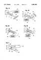
- FIGS. 1A and 1Bshow schematic, perspective views of two embodiments of an actuator for causing movement of a rod or filament, utilizing shape memory alloys, made in accordance with the principles of the present invention
- FIGS. 2A and 2Bshow schematic, perspective views of two embodiments of actuators for causing movement of a rod or filament, utilizing piezoelectric materials;
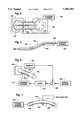
- FIG. 3is a schematic, perspective view of a sensor system for sensing movement, both the degree and direction, of a rod or filament, in accordance with the present invention
- FIG. 4is a schematic, perspective view of an actuator for causing rotational movement of an object
- FIG. 5is a schematic, perspective view of an actuator for causing the bending of a rod or filament at several locations along the length thereof;
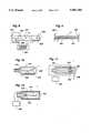
- FIG. 6is a schematic, perspective view of a feedback control system for causing controlled bending of a rod or filament
- FIG. 7is a schematic, perspective view of an electrical generator for generating electricity from a piezoelectric rod or filament
- FIG. 8is a schematic, perspective view of a slit tube valve made in accordance with the principles of the present invention.
- FIG. 9is a side, cross-sectional view of a valve, utilizing two tubes, made in accordance with the present invention.
- FIG. 10is a side, cross-sectional view of another embodiment of a valve, utilizing a bendable rod or filament, in accordance with the present invention.
- FIG. 11is a side, cross-sectional view of an accelerometer, made in accordance with the principles of the present invention.
- FIG. 12is a side, cross-sectional view of another embodiment of an accelerometer, also made in accordance with the principles of the present invention.
- FIG. 1Athere is shown a schematic, perspective view of one embodiment of a movement actuator made in accordance with the present invention.
- the actuatoris comprised of a rod 4 (the terms “rod”, “bar”, “fiber” and “filament” are used interchangeably herein to indicate an elongate element).
- the bar 4is attached or anchored at one end to a fixed support 8, with the other end being free to move in accordance with the present invention.
- the other endis shown to be pointed and is positioned adjacent a scale 12 to indicate where on the scale the free end of the bar is pointing.
- a strip 16 of shape memory alloyDisposed on one side of the bar 4 is a strip 16 of shape memory alloy which has the capability of changing its shape upon the application of external heat or electric current (which generates internal heat) to some other shape and then assuming the original shape when cooled or electric current is removed and the heat dissipates.
- shape memory alloyis nitonol comprised of about 50 percent nickel and 50 percent titanium.
- the bar 4is made of a laterally flexible material such as ceramic, metal or plastic, so that when the shape memory alloy strip 16 is caused to change shape, such as contract along its length, the bar will be caused to bend as indicated by the double headed arrow 20.
- An electrical current source 24is coupled to the strip of shape memory alloy 16 to selectively supply electrical current thereto to cause the strip to change its shape.
- the amount of current supplied to the strip 16determines the degree to which the strip changes shape and thus the degree to which the rod 4 is bent or deflected.
- An alternative to use of the strip of shape memory alloy 16is the use of a bimetal laid down in the same location as the strip 16 on the bar 4.
- a bimetalis comprised of two layers of different metals having different thermal coefficients of expansion.
- Bimetalsare well known.
- Still another alternativeis the use of piezoelectric strips on the bar 4 to cause bending of the bar in response to applied voltages.
- the diameter of the bar 4is shown to be relatively large compared to the length, these proportions are used for purposes of illustration only and it should be understood that generally the diameter would be much smaller compared to the length, and would more often resemble a thin fiber or filament, such as the fibers used in fiber optic applications.
- the strip of shape memory alloy 16could be deposited upon the bar 4 using techniques disclosed in patent application, Ser. No. 07/816,628, filed Dec. 31, 1991.
- FIG. 1Bshows a schematic, perspective view of another actuator having a rod 28 anchored at one end in a base 32 and having a strip of shape memory alloy 36 disposed in a helical pattern around the rod.
- a current source 40selectively supplies electrical current to the strip 36, the strip is caused to contract (or elongate) to thereby cause the free end of the bar 28 to twist or rotate as indicated by the double headed arrow 44.
- a pointer 48is mounted on the free end of the bar 28 to indicate by a scale 52 the amount of rotation occurring at the free end.
- shape memory alloy patternscould be provided on the side exterior of rods or filaments to cause the rods or filaments to bend, elongate, twist, contract, etc.
- a strip of shape memory alloyis disposed on a bar to extend from near the anchor end longitudinally and partially circumferentially about the bar, the bar may be caused to both bend and twist.
- FIGS. 2A and 2Bshow two embodiments of movement actuators utilizing piezoelectric material.
- FIG. 2Ais a schematic, perspective view of such a movement actuator having an elongate bar 56 anchored at one end to a base 60, and being made of a piezoelectric material such as PZT. Disposed on one side of the bar 56 in a longitudinal array are a plurality of electrically conductive elements or electrodes 64.
- a voltage source 68selectively supplies a voltage of one polarity to alternate ones of the elements 64 and a voltage of opposite polarity to the remaining elements to thereby produce a localized electric field which will cause the bar 56 to bend as generally indicated by the double headed arrow 72.
- Piezoelectric materialsof course, are well known to change shape physically in response to application of electrical voltages and to produce electrical voltages when distorted, squeezed, bent, etc.
- FIG. 2Bshows an alternative embodiment of a movement actuator again utilizing an elongate bar 76 made of a piezoelectric material.
- conductive strips 80are disposed to extend longitudinally on the bar 76.
- a voltage source 84selectively supplies voltage signals to the strips 80 to establish electric fields in the bar 76 to cause the bar to contract or extend longitudinally as indicated by the double headed arrow 88.
- both configurations in FIGS. 2A and 2Bcould be adapted to be movement sensors by simply replacing the voltage sources 68 and 84 with sensing circuitry. Then, when the piezoelectric bars 56 and 76 were bent or longitudinally compressed respectively, voltages would be developed in the bars and these voltages would be detected by the sensing circuitry to thereby sense movement of the respective bars.
- FIG. 3is a schematic, perspective view of a sensor system for sensing movement, including determination of the degree of movement and the direction of movement, of a flexible rod 92.
- the rod 92is anchored at one end in a base 102 so that the free end of the rod is subject to forces in various directions indicated by the arrows 106.
- Disposed circumferentially about the bar 92are four strain gauges 110, such as those disclosed in U.S. Pat. No. 4,964,306.
- the strain gauges 110produce signals whose magnitudes are an indication of the degree of strain occurring at the location of the strain gauges.
- the microprocessor 114calculates the direction of bending of the rod 92 and the degree of the bend, from the magnitude of the signals received from the four strain gauges 110.
- the use of three or more strain gauges spaced circumferentially about the rod 92are sufficient to determine the direction and degree of bend of the rod.
- FIG. 4is a schematic, perspective view of an actuator for causing rotational movement of an object, in this case a disk 120.
- the actuatorincludes four flexible bars 124 having fixed ends attached to a base 128 at circumferentially spaced-apart locations. The bars 124 extend outwardly from the base 128, generally in parallel with one another, to join the disk 120.
- Strips of shape memory alloy 132are disposed on the rods 124 on sides in line with the circumferential spacing of the rods, as shown, and the strips are each coupled to a current source 136. When current is applied to the strips 132, the strips cause the rods 124 to bend in a direction in line with the circumferential spacing to thereby cause the disk 120 to rotate in the direction indicated by the arrow 140.
- FIG. 5shows a flexible elongate rod 144 with shape memory alloy patches 148 disposed at longitudinally spaced-apart locations along the bar.
- a current source 152is coupled by way of a buss 156 to each of the patches 148 to selectively supply current thereto.
- the bar 144can be caused to bend at various locations along the length thereof as determined by the current source 152.
- FIG. 6shows a feedback control system for effecting controlled bending of a flexible rod 160 anchored at one end to a base 164.
- a strip of shape memory alloy 168Disposed on one side of the rod 160 is a strip of shape memory alloy 168 coupled to a current source 172 which operates to supply current to the strip 168 under control of a logic unit 176.
- a strain gauge 180Disposed on the other side of the bar 160 is a strain gauge 180 coupled to a sensor circuit 184.
- the sensor circuit 184produces a signal whose magnitude is indicative of the strain to which the bar 160 is subjected and this signal is supplied to a summing circuit 188.
- a signal source 192also supplies a signal to the summing circuit 188 in which the signal's value represents a degree of bending desired for the rod 160.
- the summing circuit 188effectively compares the two input signals and if there is a difference, it signals the logic circuit 176 as to the amount of this difference and the logic circuit, in turn, signals the current source to cause further bending (or unbending) of the rod 160 so that the output signal of the sensor 184 will move closer in value to the signal supplied by the signal source 192.
- Thisis a conventional feedback control circuit for ensuring that a result represented by an input signal is more accurately achieved, the result in this case being the bending of the rod 160.
- FIG. 7is a schematic, perspective view of an electricity generator composed of an elongate, flexible piezoelectric filament 200 disposed and held in place by bearings 204 and 208 located at the ends of the filament so that the filament follows an arc-shaped locus of points.
- a power source 212is coupled to the filament 200 to cause the filament to rotate about an axis coincident with the arc-shaped locus of points.
- the filament 200is continually stressed and compacted (that portion of the rod on the concave side of the arc being compacted and that portion of the rod on the convex side of the arc being stressed) to thereby develop voltages which are supplied to wiper elements or electrodes 216 disposed on opposite sides of the filament.
- FIGS. 8-10show three different embodiments of a valve using the technology of the present invention.
- a flexible tube 220is shown attached at a closed end to a base 224, and having an open end 228 for receiving a fluid.
- a strip of shape memory alloy 232is helically disposed about the exterior of the tube 220 and is coupled to a current source 236 which, by supplying current to the strip 232, selectively causes a change in shape of the strip to thereby cause a twisting of the tube 220 in the direction indicated by the arrow 240.
- a slit 244 formed in the side of the tubeis caused to open to allow the outflow of fluid.
- the tube 220When the tube 220 is untwisted, the slit 244 is closed to prevent the outflow of fluid. In this manner, the flow of fluid through and out the tube 220 can be controlled by controlling the twisting of the tube.
- the tube 220could be made of a resilient ceramic or hard rubber.
- FIG. 9shows another embodiment of a valve utilizing the present invention.
- two flexible tubes 250 and 254are anchored respectively on bases 258 and 262.
- the free ends of the tubesare positioned to mate together in a colinear fashion to seal the inside of the tubes from the outside when the tubes are undeflected.
- An access port 266is formed in the tube 250 to allow introduction of fluid to the inside of the tubes.
- Strips of shape memory alloyare disposed on the upper sides of the tubes 250 and 254 and are selectively heated by a current source to cause the tubes to deflect or bend upwardly, as indicated by dotted lines in FIG. 9.
- FIG. 10shows a cross-sectional, elevational view of a third embodiment of a valve which, in this case, utilizes a selectively bendable rod 270 disposed to extend from a closed end of a housing 274 towards an open end 278.
- a conical cap 282is disposed on the end of the bar 270 and is positioned in the open end 278 of the housing 274. The diameter of the conical cap 282 is greater than the opening in the open end 278 of the housing 274 so that if the cap is moved towards the closed end of the housing, it seats in the open end to seal off the inside of the housing from the outside. Fluid is introduced into the inside of the housing 274 through an inlet port 286.
- the bar 270is made of a piezoelectric material and conductive strips are disposed on the sides of the bar (not shown) so that when a voltage is supplied thereto, the bar is caused to selectively lengthen or shorten depending upon the polarity of the voltages.
- the conical cap 282is caused to seat on and close off the opening at the open end 278 of the housing 274 to prevent the outflow of fluid.
- the conical cap 278is moved outwardly from the opening to allow the outflow of fluid from inside the housing 274, as indicated by the arrows.
- FIGS. 11 and 12show side, cross-sectional views of two embodiments of an accelerometer made in accordance with the present invention.
- the accelerometeris shown to include a housing 290 in which is disposed a flexible rod 294, one end of which is fixed at one end of the housing 290 to extend toward the other end of the housing as shown.
- a field emitter 298Disposed on the free end of the rod 294 is a field emitter 298 for developing an electric field which emanates radially outwardly.
- the field detectors 302are coupled to a signal processor 306 for determining which of the field detectors 302 is producing the strongest signal, indicating that the field emitter 298 is closest to that field detector.
- the rod 294is caused to deflect in the direction opposite the acceleration to move the field emitter 298 closest to one of the plurality of field detectors 302, and the signal processor 306 determines which field detector that is and therefore in which direction the acceleration is occurring.
- the degree of deflection by the rodcan be determined by the strength of the electric field detected and this provides an indication of the magnitude of the acceleration.
- the use of field emitters and field detectors for sensing movementis well known. See U.S. Pat. No. 4,767,973.
- FIG. 12shows a side, cross-sectional view of another embodiment of an accelerometer which also includes a housing 310 in which is disposed a piezoelectric rod 314 extending from one end of the housing toward the other end. Disposed about the sides of the rod 314 are a plurality of electrically conductive elements 318 for conducting to a signal processor 322 voltages developed in the rod 314 when it is deflected. Such voltages would be developed when the housing 310 were accelerated in a direction lateral of the housing 310 and the amount of voltage developed would provide an indication of the degree of deflection of the rod 313 and thus of the magnitude of the acceleration. Also, the polarity of the voltages developed at each of the electrically conductive elements 318 would provide an indication of the direction of the acceleration.
Landscapes
- Physics & Mathematics (AREA)
- Engineering & Computer Science (AREA)
- General Physics & Mathematics (AREA)
- Microelectronics & Electronic Packaging (AREA)
- Power Engineering (AREA)
- Condensed Matter Physics & Semiconductors (AREA)
- Computer Hardware Design (AREA)
- Optics & Photonics (AREA)
- Manufacturing & Machinery (AREA)
- Mechanical Engineering (AREA)
- Automation & Control Theory (AREA)
- High Energy & Nuclear Physics (AREA)
- Plasma & Fusion (AREA)
- Human Computer Interaction (AREA)
- Theoretical Computer Science (AREA)
- Ceramic Engineering (AREA)
- Manipulator (AREA)
- Micromachines (AREA)
- Length Measuring Devices With Unspecified Measuring Means (AREA)
- Indicating Or Recording The Presence, Absence, Or Direction Of Movement (AREA)
- Vehicle Body Suspensions (AREA)
- Power Steering Mechanism (AREA)
- Regulating Braking Force (AREA)
- General Electrical Machinery Utilizing Piezoelectricity, Electrostriction Or Magnetostriction (AREA)
- Apparatus For Radiation Diagnosis (AREA)
- Testing Of Devices, Machine Parts, Or Other Structures Thereof (AREA)
- Endoscopes (AREA)
- Automotive Seat Belt Assembly (AREA)
Abstract
Description
Claims (6)
Priority Applications (16)
| Application Number | Priority Date | Filing Date | Title |
|---|---|---|---|
| US07/898,216US5481184A (en) | 1991-12-31 | 1992-06-12 | Movement actuator/sensor systems |
| CA002097668ACA2097668C (en) | 1992-06-12 | 1993-06-03 | Movement actuator/sensor systems |
| DE69320699TDE69320699T2 (en) | 1992-06-12 | 1993-06-11 | Actuator and sensor systems |
| EP97120575AEP0833163A1 (en) | 1992-06-12 | 1993-06-11 | Accelerometer |
| JP14093793AJP3824329B2 (en) | 1992-06-12 | 1993-06-11 | Mobile actuator |
| EP93109420AEP0574022B1 (en) | 1992-06-12 | 1993-06-11 | Movement actuator/sensor systems |
| AT93109420TATE170662T1 (en) | 1992-06-12 | 1993-06-11 | ADJUSTING AND SENSOR SYSTEMS |
| US08/480,018US5594330A (en) | 1991-12-31 | 1995-06-07 | Movement actuator/sensor systems |
| US08/745,003US5769389A (en) | 1991-01-28 | 1996-11-07 | Movement actuator/sensor systems |
| US08/744,381US6531861B1 (en) | 1991-01-28 | 1996-11-07 | Movement actuator/sensor systems |
| US08/744,368US5933002A (en) | 1991-01-28 | 1996-11-07 | Controlled bending actuator system |
| US08/744,380US5744947A (en) | 1991-01-28 | 1996-11-07 | Movement actuator/sensor systems |
| US08/745,000US5747692A (en) | 1991-01-28 | 1996-11-07 | Sensor system for determining acceleration |
| US08/745,002US5747993A (en) | 1991-01-28 | 1996-11-07 | Movement actuator/sensor systems |
| US10/386,375US6992474B2 (en) | 1991-01-28 | 2003-03-10 | Movement actuator/sensor systems |
| US10/867,608US6933715B2 (en) | 1991-01-28 | 2004-06-14 | Sensor system for sensing movement |
Applications Claiming Priority (2)
| Application Number | Priority Date | Filing Date | Title |
|---|---|---|---|
| US07/816,628US5269882A (en) | 1991-01-28 | 1991-12-31 | Method and apparatus for fabrication of thin film semiconductor devices using non-planar, exposure beam lithography |
| US07/898,216US5481184A (en) | 1991-12-31 | 1992-06-12 | Movement actuator/sensor systems |
Related Parent Applications (1)
| Application Number | Title | Priority Date | Filing Date |
|---|---|---|---|
| US07/816,628Continuation-In-PartUS5269882A (en) | 1991-01-28 | 1991-12-31 | Method and apparatus for fabrication of thin film semiconductor devices using non-planar, exposure beam lithography |
Related Child Applications (1)
| Application Number | Title | Priority Date | Filing Date |
|---|---|---|---|
| US08/480,018DivisionUS5594330A (en) | 1991-01-28 | 1995-06-07 | Movement actuator/sensor systems |
Publications (1)
| Publication Number | Publication Date |
|---|---|
| US5481184Atrue US5481184A (en) | 1996-01-02 |
Family
ID=25409116
Family Applications (10)
| Application Number | Title | Priority Date | Filing Date |
|---|---|---|---|
| US07/898,216Expired - LifetimeUS5481184A (en) | 1991-01-28 | 1992-06-12 | Movement actuator/sensor systems |
| US08/480,018Expired - LifetimeUS5594330A (en) | 1991-01-28 | 1995-06-07 | Movement actuator/sensor systems |
| US08/745,003Expired - LifetimeUS5769389A (en) | 1991-01-28 | 1996-11-07 | Movement actuator/sensor systems |
| US08/745,000Expired - LifetimeUS5747692A (en) | 1991-01-28 | 1996-11-07 | Sensor system for determining acceleration |
| US08/745,002Expired - Fee RelatedUS5747993A (en) | 1991-01-28 | 1996-11-07 | Movement actuator/sensor systems |
| US08/744,368Expired - LifetimeUS5933002A (en) | 1991-01-28 | 1996-11-07 | Controlled bending actuator system |
| US08/744,381Expired - Fee RelatedUS6531861B1 (en) | 1991-01-28 | 1996-11-07 | Movement actuator/sensor systems |
| US08/744,380Expired - Fee RelatedUS5744947A (en) | 1991-01-28 | 1996-11-07 | Movement actuator/sensor systems |
| US10/386,375Expired - Fee RelatedUS6992474B2 (en) | 1991-01-28 | 2003-03-10 | Movement actuator/sensor systems |
| US10/867,608Expired - Fee RelatedUS6933715B2 (en) | 1991-01-28 | 2004-06-14 | Sensor system for sensing movement |
Family Applications After (9)
| Application Number | Title | Priority Date | Filing Date |
|---|---|---|---|
| US08/480,018Expired - LifetimeUS5594330A (en) | 1991-01-28 | 1995-06-07 | Movement actuator/sensor systems |
| US08/745,003Expired - LifetimeUS5769389A (en) | 1991-01-28 | 1996-11-07 | Movement actuator/sensor systems |
| US08/745,000Expired - LifetimeUS5747692A (en) | 1991-01-28 | 1996-11-07 | Sensor system for determining acceleration |
| US08/745,002Expired - Fee RelatedUS5747993A (en) | 1991-01-28 | 1996-11-07 | Movement actuator/sensor systems |
| US08/744,368Expired - LifetimeUS5933002A (en) | 1991-01-28 | 1996-11-07 | Controlled bending actuator system |
| US08/744,381Expired - Fee RelatedUS6531861B1 (en) | 1991-01-28 | 1996-11-07 | Movement actuator/sensor systems |
| US08/744,380Expired - Fee RelatedUS5744947A (en) | 1991-01-28 | 1996-11-07 | Movement actuator/sensor systems |
| US10/386,375Expired - Fee RelatedUS6992474B2 (en) | 1991-01-28 | 2003-03-10 | Movement actuator/sensor systems |
| US10/867,608Expired - Fee RelatedUS6933715B2 (en) | 1991-01-28 | 2004-06-14 | Sensor system for sensing movement |
Country Status (6)
| Country | Link |
|---|---|
| US (10) | US5481184A (en) |
| EP (2) | EP0574022B1 (en) |
| JP (1) | JP3824329B2 (en) |
| AT (1) | ATE170662T1 (en) |
| CA (1) | CA2097668C (en) |
| DE (1) | DE69320699T2 (en) |
Cited By (21)
| Publication number | Priority date | Publication date | Assignee | Title |
|---|---|---|---|---|
| US5741429A (en)* | 1991-09-05 | 1998-04-21 | Cardia Catheter Company | Flexible tubular device for use in medical applications |
| US5941249A (en)* | 1996-09-05 | 1999-08-24 | Maynard; Ronald S. | Distributed activator for a two-dimensional shape memory alloy |
| US6027863A (en)* | 1991-09-05 | 2000-02-22 | Intratherapeutics, Inc. | Method for manufacturing a tubular medical device |
| US6063200A (en)* | 1998-02-10 | 2000-05-16 | Sarcos L.C. | Three-dimensional micro fabrication device for filamentary substrates |
| US6072154A (en)* | 1996-09-05 | 2000-06-06 | Medtronic, Inc. | Selectively activated shape memory device |
| US6107004A (en)* | 1991-09-05 | 2000-08-22 | Intra Therapeutics, Inc. | Method for making a tubular stent for use in medical applications |
| US6133547A (en)* | 1996-09-05 | 2000-10-17 | Medtronic, Inc. | Distributed activator for a two-dimensional shape memory alloy |
| US6209824B1 (en) | 1997-09-17 | 2001-04-03 | The Boeing Company | Control surface for an aircraft |
| US6337294B1 (en) | 1996-09-24 | 2002-01-08 | The Boeing Company | Elastic ground plane |
| US20020131356A1 (en)* | 2001-03-16 | 2002-09-19 | Eldredge Kenneth J. | Accelerometer using field emitter technology |
| US6466005B2 (en)* | 1999-09-28 | 2002-10-15 | Rockwell Automation Technologies, Inc. | High resolution current sensing apparatus |
| US6576406B1 (en) | 2000-06-29 | 2003-06-10 | Sarcos Investments Lc | Micro-lithographic method and apparatus using three-dimensional mask |
| US20030222635A1 (en)* | 1991-01-28 | 2003-12-04 | Jacobsen Stephen C. | Movement actuator/sensor systems |
| US20040000511A1 (en)* | 2002-07-01 | 2004-01-01 | Koninlijke Philips Electronics N.V. | Fluid-advancing fiber |
| US7045933B2 (en) | 2001-09-07 | 2006-05-16 | Caterpillar Inc | Flat actuator or sensor with internal prestress |
| US20080176661A1 (en)* | 2007-01-23 | 2008-07-24 | C-Flex Bearing Company, Inc. | Flexible coupling |
| US20090255882A1 (en)* | 2004-06-11 | 2009-10-15 | Ishida Co., Ltd. | Display Strip and Package Assembly |
| US20100072759A1 (en)* | 2007-03-21 | 2010-03-25 | The University Of Vermont And State Agricultural College | Piezoelectric Vibrational Energy Harvesting Systems Incorporating Parametric Bending Mode Energy Harvesting |
| US20100227697A1 (en)* | 2009-03-04 | 2010-09-09 | C-Flex Bearing Co., Inc. | Flexible coupling |
| US20190267916A1 (en)* | 2016-07-27 | 2019-08-29 | Denso Corporation | Actuator, sensor device and control device |
| US20220314366A1 (en)* | 2019-06-18 | 2022-10-06 | Prima Industrie S.P.A. | An apparatus of laser-processing and corresponding method of laser-processing |
Families Citing this family (88)
| Publication number | Priority date | Publication date | Assignee | Title |
|---|---|---|---|---|
| DE19539201C1 (en)* | 1995-10-20 | 1996-11-21 | Deutsche Forsch Luft Raumfahrt | Pivotal drive with rod and actuator e.g. for measurement and research, aerospace, robotics and medical technology |
| FR2745664B1 (en)* | 1996-02-29 | 1998-05-15 | Figest Bv | PROGRESSIVE WAVE PIEZOELECTRIC MOTOR |
| US5742113A (en)* | 1996-05-07 | 1998-04-21 | K Laser Technology, Inc. | Device for tilt-free translation of one plate relative to a reference plate |
| KR100195879B1 (en)* | 1996-12-21 | 1999-06-15 | 정몽규 | Door glass and its driving method |
| US5967268A (en)* | 1997-03-17 | 1999-10-19 | Tenneco Automotive Inc. | Temperature responsive damper |
| SE9704312D0 (en)* | 1997-11-24 | 1997-11-24 | Pacesetter Ab | Sensing of heart contraction |
| US6024119A (en)* | 1998-04-20 | 2000-02-15 | The United States Of America As Represented By The Secretary Of The Navy | Flow control system having actuated elastomeric membrane |
| US6275627B1 (en) | 1998-09-25 | 2001-08-14 | Corning Incorporated | Optical fiber having an expanded mode field diameter and method of expanding the mode field diameter of an optical fiber |
| US6364496B1 (en) | 1998-10-23 | 2002-04-02 | Magna Mirror Systems, Inc. | Shape memory alloy rearview mirror |
| US6151897A (en)* | 1999-04-06 | 2000-11-28 | The United States Of America As Represented By The Administrator Of The National Aeronautics And Space Administration | Shape memory alloy actuator |
| DE10026119B4 (en)* | 1999-05-26 | 2005-08-18 | Deutsches Zentrum für Luft- und Raumfahrt e.V. | Elastic arrangement |
| US6574958B1 (en)* | 1999-08-12 | 2003-06-10 | Nanomuscle, Inc. | Shape memory alloy actuators and control methods |
| US6247678B1 (en) | 1999-11-01 | 2001-06-19 | Swagelok Company | Shape memory alloy actuated fluid control valve |
| DE19956770A1 (en)* | 1999-11-25 | 2001-06-07 | Univ Muenchen Tech | Micro-positioning device; has extension element with predetermined heat expansion co-efficient connected to heat source to produce desired extension in element and device to measure extension |
| US6534999B2 (en) | 2000-11-16 | 2003-03-18 | Measurement Specialties, Inc. | Cable sensor |
| DE10156870A1 (en)* | 2000-11-22 | 2002-07-11 | Univ Ilmenau Tech | System for generating force-path steady state characteristics in linear driving mechanisms interconnects multiple single primary actuators in series/parallel in a flexible manner |
| DE10225576B4 (en)* | 2001-02-10 | 2007-05-16 | Inter Control Koehler Hermann | Thermally controlled device for actuating a valve opening |
| EP1438503B1 (en) | 2001-02-22 | 2008-04-16 | Alfmeier Präzision Ag Baugruppen und Systemlösungen | Shape memory alloy actuator with improved temperature control |
| US7280014B2 (en)* | 2001-03-13 | 2007-10-09 | Rochester Institute Of Technology | Micro-electro-mechanical switch and a method of using and making thereof |
| WO2002097865A2 (en)* | 2001-05-31 | 2002-12-05 | Rochester Institute Of Technology | Fluidic valves, agitators, and pumps and methods thereof |
| AU2002323407A1 (en)* | 2001-08-24 | 2003-03-10 | University Of Virginia Patent Foundation | Reversible shape memory multifunctional structural designs and method of using and making the same |
| WO2003038448A1 (en)* | 2001-10-26 | 2003-05-08 | Potter Michael D | An accelerometer and methods thereof |
| US7211923B2 (en)* | 2001-10-26 | 2007-05-01 | Nth Tech Corporation | Rotational motion based, electrostatic power source and methods thereof |
| US7378775B2 (en)* | 2001-10-26 | 2008-05-27 | Nth Tech Corporation | Motion based, electrostatic power source and methods thereof |
| AU2003267114A1 (en)* | 2002-05-06 | 2003-11-11 | Nanomuscle, Inc. | High stroke, highly integrated sma actuators |
| US8127543B2 (en)* | 2002-05-06 | 2012-03-06 | Alfmeier Prazision Ag Baugruppen Und Systemlosungen | Methods of manufacturing highly integrated SMA actuators |
| EP1540138B1 (en)* | 2002-05-06 | 2015-09-16 | Alfmeier Präzision AG Baugruppen und Systemlösungen | Actuator for two angular degrees of freedom |
| AU2003234522A1 (en) | 2002-05-06 | 2003-11-17 | Nanomuscle, Inc. | Reusable shape memory alloy activated latch |
| AU2003238823A1 (en)* | 2002-05-30 | 2003-12-19 | University Of Virginia Patent Foundation | Active energy absorbing cellular metals and method of manufacturing and using the same |
| DE10307360A1 (en)* | 2003-02-21 | 2004-10-07 | Ceramics Gmbh & Co. Kg | Strain sensor, especially for a piezoceramic bending transducer |
| US20040187864A1 (en)* | 2003-03-24 | 2004-09-30 | Cindet, Llc | Inhalation device and method |
| AT412456B (en)* | 2003-04-07 | 2005-03-25 | Fronius Int Gmbh | SEAM TRACKING SENSOR |
| WO2004097218A2 (en)* | 2003-04-28 | 2004-11-11 | Nanomuscle, Inc. | Flow control assemblies having integrally formed shape memory alloy actuators |
| US7082890B2 (en)* | 2003-05-02 | 2006-08-01 | Alfmeier Prazision Ag Baugruppen Und Systemlosungen | Gauge pointer with integrated shape memory alloy actuator |
| US7107842B2 (en)* | 2003-05-10 | 2006-09-19 | The Regents Of The University Of California | Angular rate sensor using micro electromechanical haltere |
| US7211344B2 (en)* | 2003-05-14 | 2007-05-01 | The Gillette Company | Fuel cell systems |
| US20060286342A1 (en)* | 2003-05-28 | 2006-12-21 | Elzey Dana M | Re-entrant cellular multifunctional structure for energy absorption and method of manufacturing and using the same |
| US7217582B2 (en) | 2003-08-29 | 2007-05-15 | Rochester Institute Of Technology | Method for non-damaging charge injection and a system thereof |
| US7287328B2 (en)* | 2003-08-29 | 2007-10-30 | Rochester Institute Of Technology | Methods for distributed electrode injection |
| US7748405B2 (en)* | 2003-09-05 | 2010-07-06 | Alfmeler Prazision AG Baugruppen und Systemlosungen | System, method and apparatus for reducing frictional forces and for compensating shape memory alloy-actuated valves and valve systems at high temperatures |
| US7007540B2 (en)* | 2003-10-31 | 2006-03-07 | Honeywell International Inc. | Methods and apparatus for conducting high g-force testing |
| US8581308B2 (en)* | 2004-02-19 | 2013-11-12 | Rochester Institute Of Technology | High temperature embedded charge devices and methods thereof |
| US7007914B2 (en) | 2004-05-14 | 2006-03-07 | United States Gypsum Company | Slurry mixer constrictor valve |
| JP4387987B2 (en)* | 2004-06-11 | 2009-12-24 | 株式会社オクテック | Microstructure inspection apparatus, microstructure inspection method, and microstructure inspection program |
| US7416534B2 (en)* | 2004-06-22 | 2008-08-26 | Boston Scientific Scimed, Inc. | Medical device including actuator |
| CN1305644C (en)* | 2004-07-30 | 2007-03-21 | 哈尔滨工业大学 | Microdriving fully decoupled macrol/micre bidriving minitype robot moving locating platform |
| US7185541B1 (en)* | 2005-02-03 | 2007-03-06 | The United States Of America As Represented By The Secretary Of The Army | MEMS magnetic device and method |
| US20070074731A1 (en)* | 2005-10-05 | 2007-04-05 | Nth Tech Corporation | Bio-implantable energy harvester systems and methods thereof |
| JP5264497B2 (en) | 2005-12-02 | 2013-08-14 | エー. デニッシュ,リー | Shape / acceleration measuring instrument and apparatus |
| US8360361B2 (en) | 2006-05-23 | 2013-01-29 | University Of Virginia Patent Foundation | Method and apparatus for jet blast deflection |
| GB0624242D0 (en)* | 2006-12-05 | 2007-01-10 | Oliver Crispin Robotics Ltd | Improvements in and relating to robotic arms |
| CZ303814B6 (en)* | 2007-09-21 | 2013-05-15 | Ceské vysoké ucení technické v Praze, | Rod-like multiaxial force sensor |
| US7836760B2 (en)* | 2007-10-23 | 2010-11-23 | Saylor David J | Method and device for the assessment of fluid collection networks |
| US7661313B2 (en)* | 2007-11-05 | 2010-02-16 | The United States Of America As Represented By The Secretary Of The Navy | Acceleration strain transducer |
| US20090143844A1 (en)* | 2007-11-29 | 2009-06-04 | Gaymar Industries, Inc. | Hose management for convective devices |
| ITBO20080504A1 (en)* | 2008-08-05 | 2010-02-06 | A M A S P A | METHOD AND DEVICE FOR MONITORING THE POSITION OF THE INDICATOR LAUNCH |
| US20100331919A1 (en)* | 2009-06-30 | 2010-12-30 | Boston Scientific Neuromodulation Corporation | Moldable charger having hinged sections for charging an implantable pulse generator |
| US20100331918A1 (en)* | 2009-06-30 | 2010-12-30 | Boston Scientific Neuromodulation Corporation | Moldable charger with curable material for charging an implantable pulse generator |
| US9399131B2 (en)* | 2009-06-30 | 2016-07-26 | Boston Scientific Neuromodulation Corporation | Moldable charger with support members for charging an implantable pulse generator |
| US8260432B2 (en)* | 2009-06-30 | 2012-09-04 | Boston Scientific Neuromodulation Corporation | Moldable charger with shape-sensing means for an implantable pulse generator |
| JP2011085514A (en)* | 2009-10-16 | 2011-04-28 | Hitachi Cable Ltd | Load measuring sensor for rod-shaped body, and load measuring system |
| EP3714848A1 (en) | 2009-10-22 | 2020-09-30 | Coolsystems, Inc. | Temperature and flow control methods in a thermal therapy device |
| WO2011055750A1 (en)* | 2009-11-09 | 2011-05-12 | 株式会社キッツ | Rotation actuator |
| GB2475890A (en)* | 2009-12-04 | 2011-06-08 | Ge Aviat Systems Ltd | Shape memory torsion actuator |
| EP2420187B1 (en)* | 2010-08-16 | 2013-02-13 | Precision Bioinstrument LLC | Individually adjustable multi-channel systems in vivo recording |
| CN102175892B (en)* | 2011-01-26 | 2013-05-01 | 边义祥 | Multidimensional acceleration sensor with cored piezoelectric rods and acceleration measurement method |
| US9000656B2 (en)* | 2011-03-15 | 2015-04-07 | Qualcomm Mems Technologies, Inc. | Microelectromechanical system device including a metal proof mass and a piezoelectric component |
| US10874466B2 (en) | 2012-06-21 | 2020-12-29 | Globus Medical, Inc. | System and method for surgical tool insertion using multiaxis force and moment feedback |
| US10646280B2 (en) | 2012-06-21 | 2020-05-12 | Globus Medical, Inc. | System and method for surgical tool insertion using multiaxis force and moment feedback |
| US9556858B2 (en) | 2013-06-20 | 2017-01-31 | Simmonds Precision Products, Inc. | Rotational actuators |
| CN104314936B (en)* | 2014-09-02 | 2016-07-06 | 广州大学 | A kind of fiber-optic grating sensor quick gummer of detection level axle or beam strain |
| DE102014219516A1 (en)* | 2014-09-26 | 2016-03-31 | Siemens Aktiengesellschaft | Optical current transformer |
| RU2579642C1 (en)* | 2015-03-03 | 2016-04-10 | Открытое акционерное общество "Научно-исследовательский институт "Полюс" им. М.Ф. Стельмаха" | Laser with optical-mechanical gate |
| RU2579548C1 (en)* | 2015-03-03 | 2016-04-10 | Открытое акционерное общество "Научно-исследовательский институт "Полюс" им. М.Ф. Стельмаха" | Laser with modulated resonator q-factor |
| CH711008A1 (en)* | 2015-04-30 | 2016-10-31 | Kistler Holding Ag | Contact force testing apparatus, use of such a contact force testing apparatus, and a method of manufacturing such a contact force testing apparatus. |
| CN104858892B (en)* | 2015-06-11 | 2017-03-01 | 佛山市南海区广工大数控装备协同创新研究院 | Modularization robot based on intelligent machine arm |
| US10537863B2 (en) | 2015-12-31 | 2020-01-21 | United States Gypsum Company | Constrictor valve with webbing, cementitious slurry mixing and dispensing assembly, and method for making cementitious product |
| KR102655412B1 (en)* | 2016-10-25 | 2024-04-08 | 한화오션 주식회사 | Welding robot |
| DE102017204729B4 (en)* | 2017-03-21 | 2019-01-10 | Zf Friedrichshafen Ag | Overload detection in a chassis component |
| JP6794892B2 (en)* | 2017-03-23 | 2020-12-02 | 株式会社デンソー | Movable device |
| JP2018159351A (en)* | 2017-03-23 | 2018-10-11 | 株式会社デンソー | Movable device |
| CN107830875B (en)* | 2017-09-14 | 2020-07-28 | 南京航空航天大学 | Shape-controllable robot bionic tentacle touch sensor and detection method |
| US11221001B2 (en) | 2018-02-20 | 2022-01-11 | Lintec Of America, Inc. | Untwisted artificial muscle |
| US10827246B1 (en)* | 2019-07-23 | 2020-11-03 | Bose Corporation | Audio device |
| CN114286732A (en)* | 2019-09-03 | 2022-04-05 | 住友电气工业株式会社 | Cutting tools, modules, cutting tool units and cutting systems |
| CN112894042B (en)* | 2021-01-25 | 2023-04-07 | 东风小康汽车有限公司重庆分公司 | Welding method for repairing nut desoldering in box-shaped part |
| GB2608843B (en)* | 2021-07-14 | 2024-02-14 | Cambridge Mechatronics Ltd | Rotary encoder |
| NL2032608B1 (en)* | 2022-07-27 | 2024-02-05 | Vdl Enabling Tech Group B V | A positioning system for positioning an object within an XYZ-system of coordinates. |
Citations (6)
| Publication number | Priority date | Publication date | Assignee | Title |
|---|---|---|---|---|
| US393132A (en)* | 1888-11-20 | Electric meter | ||
| US2928069A (en)* | 1954-10-13 | 1960-03-08 | Gulton Ind Inc | Transducer |
| US3663839A (en)* | 1971-02-24 | 1972-05-16 | Nasa | Thermal motor |
| US4281407A (en)* | 1979-12-14 | 1981-07-28 | Rca Corporation | Surface acoustic wave pickup and recording device |
| US4917579A (en)* | 1987-06-24 | 1990-04-17 | Kaileg Ab | Transporter pump |
| US4928030A (en)* | 1988-09-30 | 1990-05-22 | Rockwell International Corporation | Piezoelectric actuator |
Family Cites Families (58)
| Publication number | Priority date | Publication date | Assignee | Title |
|---|---|---|---|---|
| US2130829A (en)* | 1938-09-20 | Electrical measuring instrument | ||
| US2722614A (en)* | 1951-08-11 | 1955-11-01 | Gulton Mfg Co | Vibration and shock-responsive device |
| US3234787A (en)* | 1961-04-14 | 1966-02-15 | Baldwin Lima Hamilton Corp | Strain gage transducer with impedance means for compensating for the characteristic nonlinearity of the gage |
| US3415712A (en)* | 1963-10-31 | 1968-12-10 | Gen Electric | Bimaterial thermosensitive element |
| US3228240A (en)* | 1963-12-24 | 1966-01-11 | Alfred N Ormond | Linearization of load cells |
| US3304773A (en)* | 1964-03-26 | 1967-02-21 | Vernon L Rogallo | Force transducer |
| US3363470A (en)* | 1964-07-20 | 1968-01-16 | Raphael O. Yavne | Accelerometer |
| US3780817A (en)* | 1969-02-28 | 1973-12-25 | J Videon | Weighing devices |
| US3816774A (en)* | 1972-01-28 | 1974-06-11 | Victor Company Of Japan | Curved piezoelectric elements |
| US3914993A (en)* | 1973-06-25 | 1975-10-28 | Us Interior | Rigid testing machine |
| GB1490349A (en)* | 1974-03-18 | 1977-11-02 | Gooch & Co Ltd J | Pinch valves |
| US4046005A (en)* | 1976-06-14 | 1977-09-06 | Measurement Systems, Incorporated | Three axis joystick control |
| US4232265A (en)* | 1978-04-17 | 1980-11-04 | Smirnov Vladimir A | Device for measuring intensity of magnetic or electromagnetic fields using strain gauges mounted on ferromagnetic plates |
| GB2065882A (en)* | 1979-11-20 | 1981-07-01 | Delta Materials Research Ltd | Coated shape memory effect elements |
| FR2541775B1 (en)* | 1983-02-28 | 1985-10-04 | Onera (Off Nat Aerospatiale) | ELECTROSTATIC SUSPENSION ACCELEROMETERS |
| CH653369A5 (en)* | 1983-03-14 | 1985-12-31 | Bbc Brown Boveri & Cie | COMPOSITE MATERIAL IN BAR, TUBE, STRIP, SHEET OR PLATE SHAPE WITH REVERSIBLE THERMO-MECHANICAL PROPERTIES AND METHOD FOR THE PRODUCTION THEREOF. |
| DE3406059A1 (en)* | 1983-07-27 | 1985-02-07 | Siemens AG, 1000 Berlin und 8000 München | MULTI-COMPONENT FORCE AND TORQUE MEASURING BODIES WITH STRETCH MEASURING STRIPS |
| JPS6062497A (en)* | 1983-09-14 | 1985-04-10 | 畑村 洋太郎 | Multispindle-force sensor |
| US4520570A (en)* | 1983-12-30 | 1985-06-04 | International Business Machines Corporation | Piezoelectric x-y-positioner |
| US4555955A (en)* | 1984-01-27 | 1985-12-03 | Eaton Corporation | Combination loading transducer |
| DD222478A1 (en)* | 1984-04-05 | 1985-05-22 | Medizin Labortechnik Veb K | COMPLEMENTARY SERVICE PROVIDER FOR BREATHING VALVES, COVERS AND SLIDERS IN BREAKFAST AND WAREHOUSE |
| DE3515349A1 (en)* | 1985-04-27 | 1986-10-30 | Messerschmitt-Bölkow-Blohm GmbH, 8012 Ottobrunn | ELECTRICAL TRANSMITTER FOR MEASURING MECHANICAL SIZES |
| JPS6226532A (en)* | 1985-07-19 | 1987-02-04 | リチヤ−ド エル.ジエンキンス | Isometric controller |
| US4776844A (en)* | 1986-05-02 | 1988-10-11 | Olympus Optical Co., Ltd. | Medical tube |
| US4660607A (en)* | 1986-06-11 | 1987-04-28 | American Sigma, Inc. | Sensor controlled sampling apparatus and method |
| US5146129A (en)* | 1986-12-01 | 1992-09-08 | Canon Kabushiki Kaisha | Vibration wave motor |
| EP0275665B1 (en)* | 1986-12-18 | 1993-03-17 | Michael Anthony Smithard | Improvements in and relating to educational devices |
| US4744252A (en)* | 1987-05-19 | 1988-05-17 | The United States Of America As Represented By The United States Department Of Energy | Triple-material stress-strain resistivity gage |
| US4767973A (en)* | 1987-07-06 | 1988-08-30 | Sarcos Incorporated | Systems and methods for sensing position and movement |
| DE3801514A1 (en)* | 1988-01-20 | 1989-08-03 | Schmidt Feinmech | ACCELERATION SENSOR AND METHOD FOR THE PRODUCTION THEREOF |
| JP2614635B2 (en)* | 1988-04-12 | 1997-05-28 | 日立マクセル株式会社 | Electrostrictive rotor and single-phase ultrasonic motor |
| US4903732A (en)* | 1989-01-19 | 1990-02-27 | A. K. Allen Company | Piezoelectric valve |
| US5016481A (en)* | 1989-04-03 | 1991-05-21 | Sarcos Group | Field-based movement sensor |
| US4964306A (en)* | 1989-04-03 | 1990-10-23 | Sarcos Group | Field-based movement sensor |
| US5266801A (en)* | 1989-06-05 | 1993-11-30 | Digital Instruments, Inc. | Jumping probe microscope |
| FR2649208B1 (en)* | 1989-06-28 | 1991-10-11 | Aerospatiale | SHOCK SENSOR AND DEVICES APPLYING SAME |
| US5067512A (en)* | 1990-01-31 | 1991-11-26 | Sarcos Group | Servovalve apparatus for use in fluid systems |
| US5133379A (en)* | 1990-01-31 | 1992-07-28 | University Of Utah Research Foundation | Servovalve apparatus for use in fluid systems |
| JP3091766B2 (en)* | 1990-02-14 | 2000-09-25 | エンデブコ・コーポレーション | Surface-mounted piezoelectric ceramic accelerometer and method of manufacturing the same |
| US5056370A (en)* | 1990-07-19 | 1991-10-15 | Wolfgang Maier | Method and apparatus for testing a test piece |
| JPH0499963A (en)* | 1990-08-18 | 1992-03-31 | Fujitsu Ltd | Acceleration sensor |
| DE69119715T2 (en)* | 1990-11-29 | 1996-10-31 | Tokin Corp | Gyro with round rod as a piezo vibrator |
| JP2607396B2 (en)* | 1990-12-06 | 1997-05-07 | 株式会社トーキン | Acceleration sensor |
| JP2607395B2 (en)* | 1990-12-06 | 1997-05-07 | 株式会社トーキン | Acceleration sensor |
| US5270485A (en)* | 1991-01-28 | 1993-12-14 | Sarcos Group | High density, three-dimensional, intercoupled circuit structure |
| US5273622A (en)* | 1991-01-28 | 1993-12-28 | Sarcos Group | System for continuous fabrication of micro-structures and thin film semiconductor devices on elongate substrates |
| US5481184A (en)* | 1991-12-31 | 1996-01-02 | Sarcos Group | Movement actuator/sensor systems |
| US5106455A (en)* | 1991-01-28 | 1992-04-21 | Sarcos Group | Method and apparatus for fabrication of micro-structures using non-planar, exposure beam lithography |
| US5269882A (en)* | 1991-01-28 | 1993-12-14 | Sarcos Group | Method and apparatus for fabrication of thin film semiconductor devices using non-planar, exposure beam lithography |
| US5252870A (en)* | 1991-03-01 | 1993-10-12 | Jacobsen Stephen C | Magnetic eccentric motion motor |
| JP3198355B2 (en)* | 1991-05-28 | 2001-08-13 | キヤノン株式会社 | Small displacement element, scanning tunnel microscope using the same, and information processing apparatus |
| JPH0552572A (en)* | 1991-08-28 | 1993-03-02 | Akai Electric Co Ltd | Supporting structure for vibrator |
| JP2541891B2 (en)* | 1991-09-03 | 1996-10-09 | 龍 川邊 | Fluid flow rate control method and control apparatus |
| US5217037A (en)* | 1991-11-26 | 1993-06-08 | Apv Gaulin, Inc. | Homogenizing apparatus having magnetostrictive actuator assembly |
| JP3118660B2 (en)* | 1991-11-28 | 2000-12-18 | 株式会社トーキン | 2-axis acceleration sensor |
| US5672929A (en)* | 1992-03-03 | 1997-09-30 | The Technology Partnership Public Limited Company | Moving sensor using mechanical vibrations |
| JP3151927B2 (en)* | 1992-04-10 | 2001-04-03 | 株式会社村田製作所 | Acceleration sensor |
| CH685648A5 (en)* | 1992-10-23 | 1995-08-31 | Kk Holding Ag | Multicomponent force and moment measuring arrangement. |
- 1992
- 1992-06-12USUS07/898,216patent/US5481184A/ennot_activeExpired - Lifetime
- 1993
- 1993-06-03CACA002097668Apatent/CA2097668C/ennot_activeExpired - Fee Related
- 1993-06-11DEDE69320699Tpatent/DE69320699T2/ennot_activeExpired - Fee Related
- 1993-06-11EPEP93109420Apatent/EP0574022B1/ennot_activeExpired - Lifetime
- 1993-06-11JPJP14093793Apatent/JP3824329B2/ennot_activeExpired - Lifetime
- 1993-06-11EPEP97120575Apatent/EP0833163A1/ennot_activeWithdrawn
- 1993-06-11ATAT93109420Tpatent/ATE170662T1/ennot_activeIP Right Cessation
- 1995
- 1995-06-07USUS08/480,018patent/US5594330A/ennot_activeExpired - Lifetime
- 1996
- 1996-11-07USUS08/745,003patent/US5769389A/ennot_activeExpired - Lifetime
- 1996-11-07USUS08/745,000patent/US5747692A/ennot_activeExpired - Lifetime
- 1996-11-07USUS08/745,002patent/US5747993A/ennot_activeExpired - Fee Related
- 1996-11-07USUS08/744,368patent/US5933002A/ennot_activeExpired - Lifetime
- 1996-11-07USUS08/744,381patent/US6531861B1/ennot_activeExpired - Fee Related
- 1996-11-07USUS08/744,380patent/US5744947A/ennot_activeExpired - Fee Related
- 2003
- 2003-03-10USUS10/386,375patent/US6992474B2/ennot_activeExpired - Fee Related
- 2004
- 2004-06-14USUS10/867,608patent/US6933715B2/ennot_activeExpired - Fee Related
Patent Citations (6)
| Publication number | Priority date | Publication date | Assignee | Title |
|---|---|---|---|---|
| US393132A (en)* | 1888-11-20 | Electric meter | ||
| US2928069A (en)* | 1954-10-13 | 1960-03-08 | Gulton Ind Inc | Transducer |
| US3663839A (en)* | 1971-02-24 | 1972-05-16 | Nasa | Thermal motor |
| US4281407A (en)* | 1979-12-14 | 1981-07-28 | Rca Corporation | Surface acoustic wave pickup and recording device |
| US4917579A (en)* | 1987-06-24 | 1990-04-17 | Kaileg Ab | Transporter pump |
| US4928030A (en)* | 1988-09-30 | 1990-05-22 | Rockwell International Corporation | Piezoelectric actuator |
Cited By (34)
| Publication number | Priority date | Publication date | Assignee | Title |
|---|---|---|---|---|
| US20030222635A1 (en)* | 1991-01-28 | 2003-12-04 | Jacobsen Stephen C. | Movement actuator/sensor systems |
| US20040221658A1 (en)* | 1991-01-28 | 2004-11-11 | Jacobsen Stephen C. | Movement actuator/sensor systems |
| US6992474B2 (en) | 1991-01-28 | 2006-01-31 | Sarcos Lc | Movement actuator/sensor systems |
| US6933715B2 (en) | 1991-01-28 | 2005-08-23 | Sarcos Lc | Sensor system for sensing movement |
| US6107004A (en)* | 1991-09-05 | 2000-08-22 | Intra Therapeutics, Inc. | Method for making a tubular stent for use in medical applications |
| US6027863A (en)* | 1991-09-05 | 2000-02-22 | Intratherapeutics, Inc. | Method for manufacturing a tubular medical device |
| US5741429A (en)* | 1991-09-05 | 1998-04-21 | Cardia Catheter Company | Flexible tubular device for use in medical applications |
| US6072154A (en)* | 1996-09-05 | 2000-06-06 | Medtronic, Inc. | Selectively activated shape memory device |
| US6133547A (en)* | 1996-09-05 | 2000-10-17 | Medtronic, Inc. | Distributed activator for a two-dimensional shape memory alloy |
| US6169269B1 (en) | 1996-09-05 | 2001-01-02 | Medtronic Inc. | Selectively activated shape memory device |
| US6278084B1 (en) | 1996-09-05 | 2001-08-21 | Medtronic, Inc. | Method of making a distributed activator for a two-dimensional shape memory alloy |
| US6323459B1 (en) | 1996-09-05 | 2001-11-27 | Medtronic, Inc. | Selectively activated shape memory device |
| US5941249A (en)* | 1996-09-05 | 1999-08-24 | Maynard; Ronald S. | Distributed activator for a two-dimensional shape memory alloy |
| US6337294B1 (en) | 1996-09-24 | 2002-01-08 | The Boeing Company | Elastic ground plane |
| US6349903B2 (en)* | 1997-09-17 | 2002-02-26 | The Boeing Company | Control surface for an aircraft |
| US6209824B1 (en) | 1997-09-17 | 2001-04-03 | The Boeing Company | Control surface for an aircraft |
| US6066361A (en)* | 1998-02-10 | 2000-05-23 | Sarcos L.C. | Method for coating a filament |
| US6063200A (en)* | 1998-02-10 | 2000-05-16 | Sarcos L.C. | Three-dimensional micro fabrication device for filamentary substrates |
| US6466005B2 (en)* | 1999-09-28 | 2002-10-15 | Rockwell Automation Technologies, Inc. | High resolution current sensing apparatus |
| US6576406B1 (en) | 2000-06-29 | 2003-06-10 | Sarcos Investments Lc | Micro-lithographic method and apparatus using three-dimensional mask |
| US6791931B2 (en)* | 2001-03-16 | 2004-09-14 | Hewlett-Packard Development Company, L.P. | Accelerometer using field emitter technology |
| US20020131356A1 (en)* | 2001-03-16 | 2002-09-19 | Eldredge Kenneth J. | Accelerometer using field emitter technology |
| US7045933B2 (en) | 2001-09-07 | 2006-05-16 | Caterpillar Inc | Flat actuator or sensor with internal prestress |
| US6902549B2 (en)* | 2002-07-01 | 2005-06-07 | Koninklijke Philips Electronics, N.V. | Fluid-advancing fiber |
| US20040000511A1 (en)* | 2002-07-01 | 2004-01-01 | Koninlijke Philips Electronics N.V. | Fluid-advancing fiber |
| US20090255882A1 (en)* | 2004-06-11 | 2009-10-15 | Ishida Co., Ltd. | Display Strip and Package Assembly |
| US20080176661A1 (en)* | 2007-01-23 | 2008-07-24 | C-Flex Bearing Company, Inc. | Flexible coupling |
| US7824270B2 (en) | 2007-01-23 | 2010-11-02 | C-Flex Bearing Co., Inc. | Flexible coupling |
| US20100072759A1 (en)* | 2007-03-21 | 2010-03-25 | The University Of Vermont And State Agricultural College | Piezoelectric Vibrational Energy Harvesting Systems Incorporating Parametric Bending Mode Energy Harvesting |
| US8080920B2 (en)* | 2007-03-21 | 2011-12-20 | The University Of Vermont And State Agricultural College | Piezoelectric vibrational energy harvesting systems incorporating parametric bending mode energy harvesting |
| US20100227697A1 (en)* | 2009-03-04 | 2010-09-09 | C-Flex Bearing Co., Inc. | Flexible coupling |
| US20190267916A1 (en)* | 2016-07-27 | 2019-08-29 | Denso Corporation | Actuator, sensor device and control device |
| US10920754B2 (en)* | 2016-07-27 | 2021-02-16 | Denso Corporation | Deformable polymer fiber actuator, sensor device and control device |
| US20220314366A1 (en)* | 2019-06-18 | 2022-10-06 | Prima Industrie S.P.A. | An apparatus of laser-processing and corresponding method of laser-processing |
Also Published As
| Publication number | Publication date |
|---|---|
| US5933002A (en) | 1999-08-03 |
| EP0574022B1 (en) | 1998-09-02 |
| EP0574022A2 (en) | 1993-12-15 |
| DE69320699D1 (en) | 1998-10-08 |
| ATE170662T1 (en) | 1998-09-15 |
| US5744947A (en) | 1998-04-28 |
| CA2097668C (en) | 2000-09-26 |
| EP0833163A1 (en) | 1998-04-01 |
| US5594330A (en) | 1997-01-14 |
| EP0574022A3 (en) | 1994-02-09 |
| US6531861B1 (en) | 2003-03-11 |
| US5747993A (en) | 1998-05-05 |
| JPH077975A (en) | 1995-01-10 |
| US20040221658A1 (en) | 2004-11-11 |
| CA2097668A1 (en) | 1993-12-13 |
| US20030222635A1 (en) | 2003-12-04 |
| US6992474B2 (en) | 2006-01-31 |
| DE69320699T2 (en) | 1999-01-21 |
| US6933715B2 (en) | 2005-08-23 |
| US5747692A (en) | 1998-05-05 |
| JP3824329B2 (en) | 2006-09-20 |
| US5769389A (en) | 1998-06-23 |
Similar Documents
| Publication | Publication Date | Title |
|---|---|---|
| US5481184A (en) | Movement actuator/sensor systems | |
| US5355712A (en) | Method and apparatus for thermally actuated self testing of silicon structures | |
| Comtois et al. | Thermal microactuators for surface-micromachining processes | |
| KR100388348B1 (en) | Electromechanical Positioning Unit | |
| US6721104B2 (en) | System and method for focusing an elastically deformable lens | |
| Lai et al. | Force, deflection and power measurements of toggled microthermal actuators | |
| JP3023158B2 (en) | Mechanical-electrical displacement transducer | |
| EP0554128A1 (en) | Contraction-extension mechanism type actuator | |
| US7082890B2 (en) | Gauge pointer with integrated shape memory alloy actuator | |
| Comtois et al. | Characterization of electrothermal actuators and arrays fabricated in a four-level, planarized surface-micromachined polycrystalline silicon process | |
| US6691513B1 (en) | System and method for providing an improved electrothermal actuator for a micro-electro-mechanical device | |
| JP2017223513A (en) | Load fluctuation detector | |
| JPH106274A (en) | Force sensor device | |
| Conant et al. | Cyclic fatigue testing of surface-micromachined thermal actuators | |
| KR101731491B1 (en) | Artificial Muscle Module with Displacement Sensor | |
| JP6950427B2 (en) | Position detector | |
| Ebefors et al. | 3D micromachined devices based on polyimide joint technology | |
| KR20180077648A (en) | electrical energy harvester capable of measuring deformation and tactile force | |
| Anderson et al. | Piezoresistive sensing of bistable micro mechanism state | |
| KR102036756B1 (en) | Apparatus capable of energy generating and sensing and method of manufacturing the same | |
| KR102015476B1 (en) | Sensing and energy generation device | |
| JPH039232A (en) | Pressure detecting method and pressure sensor | |
| JP2007170836A (en) | Fine movement device and scanning probe microscope | |
| WO2004017509A2 (en) | System and method for providing a micro-electro-mechanical microengine assembly | |
| Prahlad et al. | Development of an adaptive flexbeam for rotorcraft applications using embedded shape memory alloy (SMA) actuators |
Legal Events
| Date | Code | Title | Description |
|---|---|---|---|
| AS | Assignment | Owner name:SARCOS GROUP, UTAH Free format text:ASSIGNMENT OF ASSIGNORS INTEREST;ASSIGNOR:JACOBSEN, STEPHEN C.;REEL/FRAME:006646/0267 Effective date:19930729 | |
| STCF | Information on status: patent grant | Free format text:PATENTED CASE | |
| AS | Assignment | Owner name:SARCOS GROUP, UTAH Free format text:ASSIGNMENT OF ASSIGNORS INTEREST;ASSIGNORS:JACOBSEN, STEPHEN C.;WELLS, DAVID L.;MACLEAN, BRIAN;REEL/FRAME:007895/0959 Effective date:19960131 | |
| FEPP | Fee payment procedure | Free format text:PAYOR NUMBER ASSIGNED (ORIGINAL EVENT CODE: ASPN); ENTITY STATUS OF PATENT OWNER: LARGE ENTITY | |
| FPAY | Fee payment | Year of fee payment:4 | |
| FEPP | Fee payment procedure | Free format text:PAYER NUMBER DE-ASSIGNED (ORIGINAL EVENT CODE: RMPN); ENTITY STATUS OF PATENT OWNER: LARGE ENTITY Free format text:PAYOR NUMBER ASSIGNED (ORIGINAL EVENT CODE: ASPN); ENTITY STATUS OF PATENT OWNER: LARGE ENTITY | |
| FPAY | Fee payment | Year of fee payment:8 | |
| AS | Assignment | Owner name:SARCOS LC, UTAH Free format text:ASSIGNMENT OF ASSIGNORS INTEREST;ASSIGNOR:SARCOS GROUP;REEL/FRAME:015918/0807 Effective date:20040330 | |
| FEPP | Fee payment procedure | Free format text:PAT HOLDER NO LONGER CLAIMS SMALL ENTITY STATUS, ENTITY STATUS SET TO UNDISCOUNTED (ORIGINAL EVENT CODE: STOL); ENTITY STATUS OF PATENT OWNER: LARGE ENTITY | |
| REFU | Refund | Free format text:REFUND - PAYMENT OF MAINTENANCE FEE, 12TH YR, SMALL ENTITY (ORIGINAL EVENT CODE: R2553); ENTITY STATUS OF PATENT OWNER: LARGE ENTITY | |
| FPAY | Fee payment | Year of fee payment:12 | |
| AS | Assignment | Owner name:SARCOS, L.C., UTAH Free format text:ASSIGNMENT OF ASSIGNORS INTEREST;ASSIGNOR:UNIVERSITY OF UTAH RESEARCH FOUNDATION;REEL/FRAME:019477/0560 Effective date:20070626 |