US5479966A - Quick fill fuel charge process - Google Patents
Quick fill fuel charge processDownload PDFInfo
- Publication number
- US5479966A US5479966AUS08/097,754US9775493AUS5479966AUS 5479966 AUS5479966 AUS 5479966AUS 9775493 AUS9775493 AUS 9775493AUS 5479966 AUS5479966 AUS 5479966A
- Authority
- US
- United States
- Prior art keywords
- tank
- gas
- temperature
- pressure
- mass
- Prior art date
- Legal status (The legal status is an assumption and is not a legal conclusion. Google has not performed a legal analysis and makes no representation as to the accuracy of the status listed.)
- Expired - Fee Related
Links
- 238000000034methodMethods0.000titleclaimsabstractdescription18
- 239000000446fuelSubstances0.000titledescription13
- 230000008569processEffects0.000titledescription6
- 239000007789gasSubstances0.000claimsabstractdescription93
- VNWKTOKETHGBQD-UHFFFAOYSA-NmethaneChemical compoundCVNWKTOKETHGBQD-UHFFFAOYSA-N0.000claimsabstractdescription67
- 239000003345natural gasSubstances0.000claimsabstractdescription30
- 239000002828fuel tankSubstances0.000claimsabstractdescription27
- 230000006835compressionEffects0.000claimsabstractdescription8
- 238000007906compressionMethods0.000claimsabstractdescription8
- 230000008878couplingEffects0.000claimsabstractdescription6
- 238000010168coupling processMethods0.000claimsabstractdescription6
- 238000005859coupling reactionMethods0.000claimsabstractdescription6
- 238000005259measurementMethods0.000claimsabstractdescription6
- 238000005429filling processMethods0.000claimsdescription8
- 238000004364calculation methodMethods0.000claimsdescription5
- 239000003949liquefied natural gasSubstances0.000claimsdescription2
- 239000006200vaporizerSubstances0.000description15
- 230000000694effectsEffects0.000description11
- 238000010438heat treatmentMethods0.000description10
- 238000005496temperingMethods0.000description7
- 239000003570airSubstances0.000description5
- 238000010586diagramMethods0.000description5
- 125000004122cyclic groupChemical group0.000description3
- 238000013461designMethods0.000description3
- 238000012546transferMethods0.000description3
- 239000012080ambient airSubstances0.000description2
- 238000006243chemical reactionMethods0.000description2
- 238000001816coolingMethods0.000description2
- 239000002737fuel gasSubstances0.000description2
- 230000006870functionEffects0.000description2
- 238000012544monitoring processMethods0.000description2
- 230000001105regulatory effectEffects0.000description2
- 238000012935AveragingMethods0.000description1
- 230000001133accelerationEffects0.000description1
- 238000013459approachMethods0.000description1
- 230000003190augmentative effectEffects0.000description1
- 230000009286beneficial effectEffects0.000description1
- 230000001276controlling effectEffects0.000description1
- 238000012937correctionMethods0.000description1
- 230000014509gene expressionEffects0.000description1
- 239000003673groundwaterSubstances0.000description1
- 238000010348incorporationMethods0.000description1
- 238000012986modificationMethods0.000description1
- 230000004048modificationEffects0.000description1
- 230000001151other effectEffects0.000description1
- 230000037452primingEffects0.000description1
- 238000005057refrigerationMethods0.000description1
- 238000012163sequencing techniqueMethods0.000description1
- 230000001629suppressionEffects0.000description1
- 238000012360testing methodMethods0.000description1
- 230000010512thermal transitionEffects0.000description1
- 230000008016vaporizationEffects0.000description1
Images


Classifications
- F—MECHANICAL ENGINEERING; LIGHTING; HEATING; WEAPONS; BLASTING
- F17—STORING OR DISTRIBUTING GASES OR LIQUIDS
- F17C—VESSELS FOR CONTAINING OR STORING COMPRESSED, LIQUEFIED OR SOLIDIFIED GASES; FIXED-CAPACITY GAS-HOLDERS; FILLING VESSELS WITH, OR DISCHARGING FROM VESSELS, COMPRESSED, LIQUEFIED, OR SOLIDIFIED GASES
- F17C5/00—Methods or apparatus for filling containers with liquefied, solidified, or compressed gases under pressures
- F17C5/06—Methods or apparatus for filling containers with liquefied, solidified, or compressed gases under pressures for filling with compressed gases
- F—MECHANICAL ENGINEERING; LIGHTING; HEATING; WEAPONS; BLASTING
- F17—STORING OR DISTRIBUTING GASES OR LIQUIDS
- F17C—VESSELS FOR CONTAINING OR STORING COMPRESSED, LIQUEFIED OR SOLIDIFIED GASES; FIXED-CAPACITY GAS-HOLDERS; FILLING VESSELS WITH, OR DISCHARGING FROM VESSELS, COMPRESSED, LIQUEFIED, OR SOLIDIFIED GASES
- F17C2205/00—Vessel construction, in particular mounting arrangements, attachments or identifications means
- F17C2205/01—Mounting arrangements
- F17C2205/0123—Mounting arrangements characterised by number of vessels
- F17C2205/013—Two or more vessels
- F17C2205/0134—Two or more vessels characterised by the presence of fluid connection between vessels
- F17C2205/0138—Two or more vessels characterised by the presence of fluid connection between vessels bundled in series
- F—MECHANICAL ENGINEERING; LIGHTING; HEATING; WEAPONS; BLASTING
- F17—STORING OR DISTRIBUTING GASES OR LIQUIDS
- F17C—VESSELS FOR CONTAINING OR STORING COMPRESSED, LIQUEFIED OR SOLIDIFIED GASES; FIXED-CAPACITY GAS-HOLDERS; FILLING VESSELS WITH, OR DISCHARGING FROM VESSELS, COMPRESSED, LIQUEFIED, OR SOLIDIFIED GASES
- F17C2205/00—Vessel construction, in particular mounting arrangements, attachments or identifications means
- F17C2205/03—Fluid connections, filters, valves, closure means or other attachments
- F17C2205/0302—Fittings, valves, filters, or components in connection with the gas storage device
- F17C2205/0323—Valves
- F17C2205/0326—Valves electrically actuated
- F—MECHANICAL ENGINEERING; LIGHTING; HEATING; WEAPONS; BLASTING
- F17—STORING OR DISTRIBUTING GASES OR LIQUIDS
- F17C—VESSELS FOR CONTAINING OR STORING COMPRESSED, LIQUEFIED OR SOLIDIFIED GASES; FIXED-CAPACITY GAS-HOLDERS; FILLING VESSELS WITH, OR DISCHARGING FROM VESSELS, COMPRESSED, LIQUEFIED, OR SOLIDIFIED GASES
- F17C2205/00—Vessel construction, in particular mounting arrangements, attachments or identifications means
- F17C2205/03—Fluid connections, filters, valves, closure means or other attachments
- F17C2205/0302—Fittings, valves, filters, or components in connection with the gas storage device
- F17C2205/0323—Valves
- F17C2205/0335—Check-valves or non-return valves
- F—MECHANICAL ENGINEERING; LIGHTING; HEATING; WEAPONS; BLASTING
- F17—STORING OR DISTRIBUTING GASES OR LIQUIDS
- F17C—VESSELS FOR CONTAINING OR STORING COMPRESSED, LIQUEFIED OR SOLIDIFIED GASES; FIXED-CAPACITY GAS-HOLDERS; FILLING VESSELS WITH, OR DISCHARGING FROM VESSELS, COMPRESSED, LIQUEFIED, OR SOLIDIFIED GASES
- F17C2205/00—Vessel construction, in particular mounting arrangements, attachments or identifications means
- F17C2205/03—Fluid connections, filters, valves, closure means or other attachments
- F17C2205/0302—Fittings, valves, filters, or components in connection with the gas storage device
- F17C2205/037—Quick connecting means, e.g. couplings
- F—MECHANICAL ENGINEERING; LIGHTING; HEATING; WEAPONS; BLASTING
- F17—STORING OR DISTRIBUTING GASES OR LIQUIDS
- F17C—VESSELS FOR CONTAINING OR STORING COMPRESSED, LIQUEFIED OR SOLIDIFIED GASES; FIXED-CAPACITY GAS-HOLDERS; FILLING VESSELS WITH, OR DISCHARGING FROM VESSELS, COMPRESSED, LIQUEFIED, OR SOLIDIFIED GASES
- F17C2221/00—Handled fluid, in particular type of fluid
- F17C2221/03—Mixtures
- F17C2221/032—Hydrocarbons
- F17C2221/033—Methane, e.g. natural gas, CNG, LNG, GNL, GNC, PLNG
- F—MECHANICAL ENGINEERING; LIGHTING; HEATING; WEAPONS; BLASTING
- F17—STORING OR DISTRIBUTING GASES OR LIQUIDS
- F17C—VESSELS FOR CONTAINING OR STORING COMPRESSED, LIQUEFIED OR SOLIDIFIED GASES; FIXED-CAPACITY GAS-HOLDERS; FILLING VESSELS WITH, OR DISCHARGING FROM VESSELS, COMPRESSED, LIQUEFIED, OR SOLIDIFIED GASES
- F17C2223/00—Handled fluid before transfer, i.e. state of fluid when stored in the vessel or before transfer from the vessel
- F17C2223/01—Handled fluid before transfer, i.e. state of fluid when stored in the vessel or before transfer from the vessel characterised by the phase
- F17C2223/0107—Single phase
- F17C2223/0123—Single phase gaseous, e.g. CNG, GNC
- F—MECHANICAL ENGINEERING; LIGHTING; HEATING; WEAPONS; BLASTING
- F17—STORING OR DISTRIBUTING GASES OR LIQUIDS
- F17C—VESSELS FOR CONTAINING OR STORING COMPRESSED, LIQUEFIED OR SOLIDIFIED GASES; FIXED-CAPACITY GAS-HOLDERS; FILLING VESSELS WITH, OR DISCHARGING FROM VESSELS, COMPRESSED, LIQUEFIED, OR SOLIDIFIED GASES
- F17C2223/00—Handled fluid before transfer, i.e. state of fluid when stored in the vessel or before transfer from the vessel
- F17C2223/03—Handled fluid before transfer, i.e. state of fluid when stored in the vessel or before transfer from the vessel characterised by the pressure level
- F17C2223/036—Very high pressure (>80 bar)
- F—MECHANICAL ENGINEERING; LIGHTING; HEATING; WEAPONS; BLASTING
- F17—STORING OR DISTRIBUTING GASES OR LIQUIDS
- F17C—VESSELS FOR CONTAINING OR STORING COMPRESSED, LIQUEFIED OR SOLIDIFIED GASES; FIXED-CAPACITY GAS-HOLDERS; FILLING VESSELS WITH, OR DISCHARGING FROM VESSELS, COMPRESSED, LIQUEFIED, OR SOLIDIFIED GASES
- F17C2227/00—Transfer of fluids, i.e. method or means for transferring the fluid; Heat exchange with the fluid
- F17C2227/03—Heat exchange with the fluid
- F17C2227/0367—Localisation of heat exchange
- F17C2227/0388—Localisation of heat exchange separate
- F17C2227/0393—Localisation of heat exchange separate using a vaporiser
- F—MECHANICAL ENGINEERING; LIGHTING; HEATING; WEAPONS; BLASTING
- F17—STORING OR DISTRIBUTING GASES OR LIQUIDS
- F17C—VESSELS FOR CONTAINING OR STORING COMPRESSED, LIQUEFIED OR SOLIDIFIED GASES; FIXED-CAPACITY GAS-HOLDERS; FILLING VESSELS WITH, OR DISCHARGING FROM VESSELS, COMPRESSED, LIQUEFIED, OR SOLIDIFIED GASES
- F17C2227/00—Transfer of fluids, i.e. method or means for transferring the fluid; Heat exchange with the fluid
- F17C2227/04—Methods for emptying or filling
- F17C2227/043—Methods for emptying or filling by pressure cascade
- F—MECHANICAL ENGINEERING; LIGHTING; HEATING; WEAPONS; BLASTING
- F17—STORING OR DISTRIBUTING GASES OR LIQUIDS
- F17C—VESSELS FOR CONTAINING OR STORING COMPRESSED, LIQUEFIED OR SOLIDIFIED GASES; FIXED-CAPACITY GAS-HOLDERS; FILLING VESSELS WITH, OR DISCHARGING FROM VESSELS, COMPRESSED, LIQUEFIED, OR SOLIDIFIED GASES
- F17C2250/00—Accessories; Control means; Indicating, measuring or monitoring of parameters
- F17C2250/04—Indicating or measuring of parameters as input values
- F17C2250/0404—Parameters indicated or measured
- F17C2250/043—Pressure
- F—MECHANICAL ENGINEERING; LIGHTING; HEATING; WEAPONS; BLASTING
- F17—STORING OR DISTRIBUTING GASES OR LIQUIDS
- F17C—VESSELS FOR CONTAINING OR STORING COMPRESSED, LIQUEFIED OR SOLIDIFIED GASES; FIXED-CAPACITY GAS-HOLDERS; FILLING VESSELS WITH, OR DISCHARGING FROM VESSELS, COMPRESSED, LIQUEFIED, OR SOLIDIFIED GASES
- F17C2250/00—Accessories; Control means; Indicating, measuring or monitoring of parameters
- F17C2250/04—Indicating or measuring of parameters as input values
- F17C2250/0404—Parameters indicated or measured
- F17C2250/0439—Temperature
- F—MECHANICAL ENGINEERING; LIGHTING; HEATING; WEAPONS; BLASTING
- F17—STORING OR DISTRIBUTING GASES OR LIQUIDS
- F17C—VESSELS FOR CONTAINING OR STORING COMPRESSED, LIQUEFIED OR SOLIDIFIED GASES; FIXED-CAPACITY GAS-HOLDERS; FILLING VESSELS WITH, OR DISCHARGING FROM VESSELS, COMPRESSED, LIQUEFIED, OR SOLIDIFIED GASES
- F17C2250/00—Accessories; Control means; Indicating, measuring or monitoring of parameters
- F17C2250/04—Indicating or measuring of parameters as input values
- F17C2250/0404—Parameters indicated or measured
- F17C2250/0443—Flow or movement of content
- F—MECHANICAL ENGINEERING; LIGHTING; HEATING; WEAPONS; BLASTING
- F17—STORING OR DISTRIBUTING GASES OR LIQUIDS
- F17C—VESSELS FOR CONTAINING OR STORING COMPRESSED, LIQUEFIED OR SOLIDIFIED GASES; FIXED-CAPACITY GAS-HOLDERS; FILLING VESSELS WITH, OR DISCHARGING FROM VESSELS, COMPRESSED, LIQUEFIED, OR SOLIDIFIED GASES
- F17C2250/00—Accessories; Control means; Indicating, measuring or monitoring of parameters
- F17C2250/06—Controlling or regulating of parameters as output values
- F17C2250/0605—Parameters
- F17C2250/0636—Flow or movement of content
- F—MECHANICAL ENGINEERING; LIGHTING; HEATING; WEAPONS; BLASTING
- F17—STORING OR DISTRIBUTING GASES OR LIQUIDS
- F17C—VESSELS FOR CONTAINING OR STORING COMPRESSED, LIQUEFIED OR SOLIDIFIED GASES; FIXED-CAPACITY GAS-HOLDERS; FILLING VESSELS WITH, OR DISCHARGING FROM VESSELS, COMPRESSED, LIQUEFIED, OR SOLIDIFIED GASES
- F17C2250/00—Accessories; Control means; Indicating, measuring or monitoring of parameters
- F17C2250/07—Actions triggered by measured parameters
- F17C2250/072—Action when predefined value is reached
- F17C2250/075—Action when predefined value is reached when full
- F—MECHANICAL ENGINEERING; LIGHTING; HEATING; WEAPONS; BLASTING
- F17—STORING OR DISTRIBUTING GASES OR LIQUIDS
- F17C—VESSELS FOR CONTAINING OR STORING COMPRESSED, LIQUEFIED OR SOLIDIFIED GASES; FIXED-CAPACITY GAS-HOLDERS; FILLING VESSELS WITH, OR DISCHARGING FROM VESSELS, COMPRESSED, LIQUEFIED, OR SOLIDIFIED GASES
- F17C2260/00—Purposes of gas storage and gas handling
- F17C2260/02—Improving properties related to fluid or fluid transfer
- F17C2260/025—Reducing transfer time
- F—MECHANICAL ENGINEERING; LIGHTING; HEATING; WEAPONS; BLASTING
- F17—STORING OR DISTRIBUTING GASES OR LIQUIDS
- F17C—VESSELS FOR CONTAINING OR STORING COMPRESSED, LIQUEFIED OR SOLIDIFIED GASES; FIXED-CAPACITY GAS-HOLDERS; FILLING VESSELS WITH, OR DISCHARGING FROM VESSELS, COMPRESSED, LIQUEFIED, OR SOLIDIFIED GASES
- F17C2260/00—Purposes of gas storage and gas handling
- F17C2260/02—Improving properties related to fluid or fluid transfer
- F17C2260/026—Improving properties related to fluid or fluid transfer by calculation
- F—MECHANICAL ENGINEERING; LIGHTING; HEATING; WEAPONS; BLASTING
- F17—STORING OR DISTRIBUTING GASES OR LIQUIDS
- F17C—VESSELS FOR CONTAINING OR STORING COMPRESSED, LIQUEFIED OR SOLIDIFIED GASES; FIXED-CAPACITY GAS-HOLDERS; FILLING VESSELS WITH, OR DISCHARGING FROM VESSELS, COMPRESSED, LIQUEFIED, OR SOLIDIFIED GASES
- F17C2265/00—Effects achieved by gas storage or gas handling
- F17C2265/06—Fluid distribution
- F17C2265/065—Fluid distribution for refuelling vehicle fuel tanks
Definitions
- the inventionrelates to improvements in gaseous tank filling processes.
- the excess thermal energyis manifested as an increase in temperature of the gas inventory in the container, over and above the at-rest temperature in any receiver or storage vessel used to supply the gas to the fueling line. Typically dissipation of this excess thermal energy from the fuel container to the environment requires several hours, while a typical natural gas vehicle fast fill operation takes place in less than 10 minutes.
- the inventionprovides precise remedies for the first-named cause of temperature increase as described above in natural gas vehicle compressed natural gas fuel containers (tanks) during fast filling operations.
- the inventionprovides methods and apparatus for fast filling a tank with a high pressure gas wherein compensation is automatically made for the inherent heating of the gas as described above as it is introduced to the tank.
- a proper mass charge of gascan be introduced in the filling process with the result that at equilibrium where the tank is stabilized with ambient temperature, the pressure charge is at the full nominal pressure rating of the tank.
- the inventionis particularly useful in a vehicle refueling station since it can determine an appropriate compensation for tanks of various size and essentially any level of residual pressure present in the vehicle's on board fuel tanks when the vehicle is presented for fueling.
- a supply line or hoseis coupled to the vehicle tank to be filled or refilled.
- the pressure in the vehicle tankis measured by a sensor responsive to the pressure, at the hose nozzle outlet, that is required to admit gas into the tank through any check valve at its inlet port.
- a measured mass of gasis introduced into the vehicle tank from the supply hose.
- the incremental increase in pressure in the vehicle tank due to the addition of the measured charge or massis used to calculate the volume of the vehicle tank.
- the calculated value of volumeis then utilized to establish the total mass that should reside in the vehicle tank under its nominal pressure and at a standard ambient temperature of, for instance, 70° F. (530° R.).
- Measurements of temperature, pressure, mass and other dataare communicated to and registered in a controller that includes a microprocessor or simple computer.
- the computercan compute the vehicle tank volume and mass of gas to be added that will result in fully filled fuel tanks at equilibrium, and can then control the dispensing of the computed mass into the vehicle tank.
- the computercan be used to control any sequencing of valves of a cascade bank of supply tanks.
- the heating of the gas in the vehicle fuel tankis compensated for by supplying the refueling gas at a subambient temperature.
- the heat generated in the filling processis absorbed by the refueling gas introduced into the vehicle tank in a manner calculated to result in a condition where at the end of the filling cycle the gas is raised to ambient temperature.
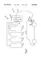
- FIG. 1is a schematic drawing of a refueling station constructed in accordance with one embodiment of the invention
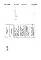
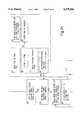
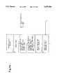
- FIGS. 2a, 2b, 2c, 2d, 2e, 2f and 2gillustrate a generalized flow chart diagram in which the process of the invention of FIG. 1 is executed;
- FIG. 3is a schematic drawing of a refueling station constructed in accordance with another embodiment of the invention.
- FIGS. 4, 4a, 4b, 4c, 4d and 4ecomprise a second generalized flow chart diagram in which the process of the invention of FIG. 3 is executed.
- a supply line or fill hose 21 from the meter 18has a nozzle 20 adapted to be connected to an inlet port coupling or receptacle 22 for the fuel tank 16 of the vehicle 13.
- the dispensing apparatus 14preferably includes temperature sensors for measuring the outside temperature TOUT, fueling site temperature TSITE, and garage temperature TGAR.
- the outside temperature TOUTis the ambient outside air temperature.
- the fueling site temperature TSITEis that of any outside sheltered area where the apparatus 14 is situated having a temperature different than the ambient outside air temperature and the garage temperature TGAR is the temperature of any garage existing where a vehicle may be stored before being refueled.
- the apparatus 14includes a sensor for monitoring the temperature of fuel being delivered by the hose 21 through the nozzle 20.
- the apparatus 14includes a pressure sensor, for example, at the outlet of the nozzle 20, for monitoring the pressure of fuel gas in the nozzle at the coupling 22. The pressure and temperature sensors are all connected to provide appropriate signals to the controller 19.
- FIGS. 2a through 2gOperation of the refueling station 10 is described with reference to the flow chart diagram of FIGS. 2a through 2g, inclusive which are to be understood as being continuous from sheet to sheet.
- the total vehicle fuel tank volume capacity as well as the level of depletioncan vary from vehicle to vehicle.
- the inventionovercomes the problem of insufficient filling of a vehicle fuel tank due to heating of the gas in the fuel tank above the supply temperature primarily from adiabatic compression of gas in the vehicle tank and from other secondary factors as noted in the Prior Art section.
- the FIG. 2 flow chart diagramexplains the automatic operations of the controller 19 in the successive boxes and that of the other components of the apparatus 14 in recharging or refueling the fuel tank 16 of the vehicle 13.
- the fueling nozzle 20is coupled to the vehicle fuel tank 16 through the coupling 22 and a start switch is actuated.
- the controller 19performs the operations described and registers the identified temperatures discussed above where appropriate.
- Box 4reflects a temperature adjustment calculation for the nominal pressure capacity of a 3,000 psi tank. The corrected pressure is given as PNOM or P2 in the formula at the right of box 4.
- P1is 3,000 psi plus atmospheric pressure of 15 psi; T1 is 70° F. or 530° R.;
- Z1 and Z2are compressibility factors for natural gas at P1 and P2, respectively, from known tables stored in the memory of the controller 19.
- P2is estimated and can be iterated as desired.
- the solenoid valve 17which is an on/off flow control valve, is opened for one second to pressurize the supply or fill hose 21.
- this hose pressureis read and registered.
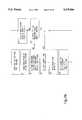
- the pressure sensor responsive to this pressureis connected to the feed hose and is therefore external and remote from the vehicle fuel tank.
- the solenoid valve 17closes under the proper conditions (boxes 9 and 12 lead to box 13), the pressure in the fill hose falls essentially to the pressure of the gas in the vehicle fuel tank (PTANK1).
- the controller 19registers the mass flow of gas into the vehicle tank that was introduced at the operation of box 7.
- the solenoidis opened for a predetermined period of, for example, 5 seconds and then closed.
- the new pressure of the vehicle tank developed by the increased mass introduced into the tank at the operation of box 15is read and registered.
- the new measured vehicle tank pressure PTANK2exceeds the original measured vehicle tank pressure PTANK1 by, for example, 100 psi, it can be assumed that reasonably accurate calculations can be made to determine the as yet unknown volume of the tank 16 of the vehicle 13.
- the operation of box 23is performed to determine the mass added in the solenoid open operation of box 15 and the operation of box 24 is performed to establish the temperature of the supplied fuel P2 as measured by the sensor in the hose 21.
- the controller 19retrieves the compressibility factor Z from known gas data stored or inserted into memory for an average pressure of PTANK1 and PTANK2.
- the previously unknown volume of the vehicle tank and the corresponding full tank fuel masscan now be calculated by the controller 19 from the observed data at box 26 according to the formulas set out to the left of box 26.
- the factor 16allows the gas mass to be expressed in pounds.
- Ris the universal gas constant.
- P1 and P2are PTANK1 and PTANK2, respectively.
- the number 3,015represents a nominal tank reading of 3,000 psi plus atmospheric pressure; 530° R. is the Rankine temperature scale value of 70° F. and Z2 is the non-ideal gas correction for natural gas at 70° F.
- the operation of boxes 28 and 29follow the equations at their left.
- the mass M6 of fuel gas to be added to the vehicle fuel tank to obtain a full fillis calculated. This is the amount of gas mass that, ideally, will result in a pressure equal to the nominal design pressure capacity of the tank when the vehicle tank and the gas therein reach thermal equilibrium at a design point of for example 70° F.
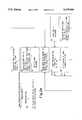
- the solenoidis opened (at box 33) and, under typical conditions, the valve is held open until the total measured mass M7 equals the mass M6 calculated to be needed for a full fill.
- the operationcan jump to box 51, box 53 and box 57 to complete a filling cycle and release the vehicle.
- Boxes 39 through 42represent a recalibration loop for a fueling time update that enables a check for potential mishaps.
- Boxes 45 and 46represent a cascade sequence loop executed by the controller.
- Boxes 47 through 50represent a low relative supply pressure filling loop.
- Boxes 52 through 56represent a top-off or final fill cycle loop.
- the maximum cyclic pressureis 125% of the tank's nominal pressure rating. For example, a tank with a nominal pressure rating of 3,000 psi is cycle tested to 3,750 psi during certification testing. This value can be input to the controller as an additional criteria for checking PTANK3, so that when reached, the fueling operation is terminated.
- FIG. 3there is shown a refueling station 50 similar to the station 10 illustrated in FIG. 1 except the supply of natural gas is stored at the station as liquified natural gas (LNG).
- LNGliquified natural gas
- Examples of apparatus and methods of converting LNG to high pressure compressed natural gas vaporare set forth in U.S. Pat. No. 5,107,906 to Swenson et al. the disclosure of which is incorporated herein by reference.
- the LNGis stored in an insulated tank 51 from which it is moved on demand by a pump 52 through a vaporizer 53.
- the pump 52is preferably divided into two sections, 52a and 52b, where 52a is a low pressure rise priming pump and 52b is a high pressure rise pump, typically three stages, which is driven by a variable speed motor 52c which is controlled by a controller 56 more fully described below for the purpose of regulating the pressure of the vaporized gas, delivered to a dispensing apparatus 57, to the desired supply pressure (PSUP).
- the vaporizer 53includes a source of heat, diagrammatically indicated at 54, such as ambient air, ground water, or a combustor of natural gas. The amount of heat supplied to the vaporizer is regulated by the controller 56 so as to supply natural gas vapor at a desired temperature as discussed more fully below.
- the vaporizer 53is preferably divided into two sections, 53a and 53b, each with associated heat sources 54a and 54b.
- Vaporizer section 53ais now a primary vaporizer and 53b is now a tempering heat exchanger that tempers the vaporized gas delivered to the dispenser apparatus 57 to the desired supply temperature (TSUP), in a manner similar to the two step vaporizing method set forth in U.S. Pat. No. 5,107,906 cited above.
- a receiver 55is positioned between the primary vaporizer 53a and the tempering heat exchanger 53b for the purpose of averaging any temperature fluctuations induced in the gas in the primary vaporizer 53a, and also for the purpose of storing a relatively large volume of vaporized but untempered gas at PSUP, such that one or more vehicles 13 can be fueled on demand without restarting pump 52 for each fueling occurrence.
- the amount of heat supplied to the vaporizer 53acan be conveniently controlled by the controller 56 by means of a heat source bypass circuit 53c, and likewise for the tempering heat exchanger 53b by a heat source bypass circuit 53d.
- the purpose of controlling heat source bypass circuit 53cis to maintain the temperature of the untempered gas delivered to the receiver 55 as sensed by sensor 53e, within a range compatible with the limited capacity of the tempering heat exchanger 53b to deliver gas to the dispenser 57 (described below) at the desired temperature TSUP.
- the heat source bypass circuit 53dis controlled to ensure that the temperature of gas delivered to the dispenser 57, as sensed by sensor 53f, is the desired temperature TSUP.
- the tempering heat exchanger 53bmay in some instances, be called upon to remove heat from the vaporized but untempered gas contained in receiver 55. This will also be the case when untempered gas is stored for a long period of time in receiver 55 and thereby warmed by heat transferred through the walls of receiver 55 to local ambient temperature (TOUT) which will usually be higher than the desired temperature TSUP, as determined by the method explained below.
- tempering heat exchanger 53bIn those instances where the tempering heat exchanger 53b is called upon to remove heat from the untempered gas flowing from receiver 55 heat source 54b becomes a heat sink colder than TSUP, and supplies refrigeration to tempering heat exchanger 53b.
- the LNG storage tank 51is an example of a heat sink colder than TSUP.
- the refueling station 50includes the dispensing apparatus 57 for supplying high pressure compressed natural gas from the vaporizer or source 53 to a vehicle 13 through a fill or fueling hose 21.
- the vehicle 13 and fueling hose or line 21are like that described in connection with FIG. 1.
- the dispenser apparatus 57includes the controller 56 in the form of a microprocessor or small computer which in addition to performing the control functions for the pump 52 and vaporizer 53 described above, receives signals from sensors at the site to monitor the outside air temperature (TOUT), the air temperature of the site (TSITE) and the garage temperature (TGAR)in the manner of the controller 19 of FIG. 1.
- the controller 56communicates with a sensor that measures the pressure (PSUP) and the sensor 53f that measures the temperature (TSUP) of the gas being supplied from the outlet of the supply vaporizer 53.
- PSUPpressure
- TSUPtemperature
- the pressure of the supply vaporizeris determined by the pressure output of the pump 52 which is controlled by the controller 56 as described above.
- the controller 56operates to automatically open and close a solenoid flow control valve 58 to selectively connect the gas supply vaporizer 53 to the fueling hose 21. Additionally, the controller 56 communicates with a pressure sensor responsive to the pressure in the fueling hose 21 which in the flow chart of FIG. 4 at appropriate times represents the values PTANK1 and PTANK2.
- FIGS. 4a through 4ethere is shown a continuous flow chart diagram that depicts the operations of the controller 56 and other components Of the dispensing apparatus 57 to refuel the vehicle 13.
- the operations of boxes 1 through 4are as described above in connection with FIG. 2.
- the controller 56selects an initial gas supply pressure (PSUP) of, for example, 1,000 psi and signals the pump 52 to produce the same.
- PSUPinitial gas supply pressure
- the solenoid valve 58is opened by the controller 56 for one second, for example, to pressurize the fueling hose 21 such that the check valve associated with coupler 22 opens.
- PSUPinitial gas supply pressure
- this stepfollowing closing of the solenoid valve 58 and assuming the supply pressure (PSUP) is sufficiently high, allows the pressure in the fueling hose (PTANK1) to assume the pressure of the vehicle tank, less any difference resulting from flow pressure drop across the check valve or the like at the inlet port or coupler 22 which difference is assumed to be negligible.
- PSUPsupply pressure
- PTANK1pressure in the fueling hose
- an initial estimated fueling timeis assigned based on experience and can be in the order of a period of two or three minutes.
- Box 14reflects the operation of the controller 56 in establishing or assigning a temperature (TTANK) of the vehicle tank 16 by selecting the lowest value of temperature from box 14.
- TTANKa temperature of the vehicle tank 16 by selecting the lowest value of temperature from box 14.
- the lowest temperatureis selected as a matter of safety inasmuch as this results in a maximum estimate by the controller 56 of the residual inventory of fuel in the tank(s) 16 of the vehicle presented for fueling.
- the controller 56sets a desired final tank temperature (TFINAL) of, for example, 70° F. or 530° R. and a tank pressure (PFINAL) of, for example, 3,015 psi. These values correspond to typical rating values for vehicle pressure fuel tanks presently commercially used.
- the formula for TSUPdepends on the initial vehicle tank pressure (PTANK1) referenced in box 8, the initial temperature of the vehicle tank (TTANK1) referenced in box 14, the final vehicle tank pressure (PFINAL) set, for example, at 3,015 psi for a nominal 3,000 psi rated tank and a final temperature of the tank (TFINAL) set, for example, at 70° F. or 530° R., both of the values being indicated in box 15.
- the calculated value of TSUPis sufficiently low to compensate for the heat of compression of gas in the vehicle tank which is described above with the result that when the filling operation is complete, the tank will substantially be filled with compressed natural gas at the nominal rating of the tank, in this instance, 3,000 psi at 70° F.
- the controller 56after calculating TSUP opens the fueling solenoid valves 58 at box 20 and reads the tank pressure at the fill hose (PTANK2) at box 21. During this ensuing vehicle tank filling process, the controller 56 regulates the heat source 54 to maintain the temperature of the gas being fed to the vehicle at the calculated TSUP.
- the controller 56determines the measured tank pressure PTANK2 to be equal to PFINAL (at box 22) it shuts off the fueling solenoid valve 58 (box 35) and in the simplest case, reaffirms the equality of these pressures (at box 37) whereupon the filling operation is completed (by passage to the operation of box 40).
- Boxes 10 and 11represent a supply pressure control loop which the controller 56 executes to increase the supply pressure as necessary. This can be accomplished by a signal to the pump motor 52c, for example, as described above.
- the check of box 17can be performed to assure that the temperature values assigned to the temperature TSUP of the supply gas remains at practical limits for the ambient conditions. Practicality will be determined by the fuel tank's capability to endure the thermal transition represented by the difference in TSUP and TOUT.
- the control loop of boxes 25 through 28provides a fill time check to reduce the risk of a mishap due to over filling.
- Boxes 31 and 32represent a control supply pressure loop performed by the controller.
- Boxes 36 to 39form a top off loop for assuring that the tank is substantially completely filled with a measured pressure PTANK2 measured by the sensor in the filling hose 21 equal to the calculated desired PFINAL.
- the heating of the gas in the vehicle fuel tankis compensated for by supplying the refueling gas at a subambient temperature and furthermore the accuracy of the compensation is corroborated by a mass flow meter.
- This third embodiment of the inventioninvolves the incorporation of a mass flow meter's output as corroboration of the correctness of the fuel inventory as specified by TSUP and PFINAL (according to the second embodiment disclosed above).
- a practical method of improving the second embodimentis thus to accept the mass flow meter's prediction of a full fill as described in the first embodiment and apply it as a check on fueling under embodiment No. 2.
- the controller of FIG. 3is programmed to execute the steps of FIG. 4 including that to calculate a desired fuel supply temperature TSUP.
- the controlleris also programmed to execute the relevant steps of FIG. 2 to calculate the mass of gas to be added (box 30 and the preceding operations).
- the second embodimentpresupposes a supply of refrigerated gas relative to the local environment, either deliberately refrigerated for the purposes of the second embodiment temperature compensation or because it had been delivered to the fueling station site as liquid natural gas (LNG).
- LNGliquid natural gas
- a greater temperature compensation effect of using gas at a temperature below the calculated correct supply temperature TSUP of the second embodimentcan be employed.
- a margin of compensationcan be applied without economic penalty. Typically, this margin would not necessarily be more than 30° F. below the TSUP calculated in the second embodiment.
Landscapes
- Engineering & Computer Science (AREA)
- Mechanical Engineering (AREA)
- General Engineering & Computer Science (AREA)
- Filling Or Discharging Of Gas Storage Vessels (AREA)
Abstract
Description
Claims (3)
Priority Applications (2)
| Application Number | Priority Date | Filing Date | Title |
|---|---|---|---|
| US08/097,754US5479966A (en) | 1993-07-26 | 1993-07-26 | Quick fill fuel charge process |
| CA002128819ACA2128819A1 (en) | 1993-07-26 | 1994-07-26 | Quick-fill fuel charge process |
Applications Claiming Priority (1)
| Application Number | Priority Date | Filing Date | Title |
|---|---|---|---|
| US08/097,754US5479966A (en) | 1993-07-26 | 1993-07-26 | Quick fill fuel charge process |
Publications (1)
| Publication Number | Publication Date |
|---|---|
| US5479966Atrue US5479966A (en) | 1996-01-02 |
Family
ID=22264956
Family Applications (1)
| Application Number | Title | Priority Date | Filing Date |
|---|---|---|---|
| US08/097,754Expired - Fee RelatedUS5479966A (en) | 1993-07-26 | 1993-07-26 | Quick fill fuel charge process |
Country Status (2)
| Country | Link |
|---|---|
| US (1) | US5479966A (en) |
| CA (1) | CA2128819A1 (en) |
Cited By (60)
| Publication number | Priority date | Publication date | Assignee | Title |
|---|---|---|---|---|
| EP0723144A3 (en)* | 1995-01-20 | 1997-01-02 | Tech Ueberwachungs Verein Oest | Method for testing the pressure of a liquid gas container used for storing a liquid gas |
| EP0743485A3 (en)* | 1995-05-17 | 1997-01-15 | Daimler Benz Ag | Gas cylinder filling device for a bus operating on gas |
| US5641005A (en)* | 1994-12-02 | 1997-06-24 | Gas Research Institute | System and method for charging a container with pressurized gas |
| WO1998036211A1 (en)* | 1997-02-14 | 1998-08-20 | Tankanlagen Salzkotten Gmbh | Natural gas refuelling method |
| WO1999003698A1 (en)* | 1997-07-16 | 1999-01-28 | M-Tec Gastechnologie Gmbh | Pressurized gas container for a vehicle, method for filling the same and gas filling facility |
| US6360793B1 (en) | 1999-02-08 | 2002-03-26 | Yamaha Hatsudoki Kabushiki Kaisha | Fast fill method and apparatus |
| EP1205704A1 (en)* | 2000-11-08 | 2002-05-15 | GreenField AG | Process for filling a vehicle tank with gas |
| EP1004779A3 (en)* | 1998-11-27 | 2003-05-28 | Linde AG | Method and device for gas supply and recuperation |
| US6672340B2 (en) | 2000-11-08 | 2004-01-06 | Greenfield Ag | Method for filling a vehicle fuel tank with gas |
| US6901973B1 (en)* | 2004-01-09 | 2005-06-07 | Harsco Technologies Corporation | Pressurized liquid natural gas filling system and associated method |
| US7159625B1 (en) | 2005-05-25 | 2007-01-09 | David Klutts | Device for verifying amount of dispensed gasoline and method of use |
| FR2896028A1 (en)* | 2006-01-06 | 2007-07-13 | Air Liquide | METHOD AND DEVICE FOR FILLING GAS CONTAINERS UNDER PRESSURE |
| WO2008017534A1 (en)* | 2006-08-07 | 2008-02-14 | Robert Bosch Gmbh | Method for detecting impurities in a gas tank |
| EP1693611A3 (en)* | 2005-02-17 | 2008-03-05 | Air Products and Chemicals, Inc. | Method and apparatus for dispensing compressed gas |
| EP1942300A1 (en)* | 2007-01-04 | 2008-07-09 | Air Products and Chemicals, Inc. | Hydrogen dispensing station and method of operating the same |
| CN100451438C (en)* | 2007-05-16 | 2009-01-14 | 马磊 | Automatic gasifying and gas adding device for energy saving type gasifying natural gas |
| US20090071565A1 (en)* | 2007-09-13 | 2009-03-19 | Denis Ding | Modular production design of compressed natural gas compressor and multi-saturation liquefied natural gas dispenser systems |
| US20090199926A1 (en)* | 2008-02-07 | 2009-08-13 | Wilfried-Henning Reese | Hydrogen fueling |
| US7647194B1 (en)* | 2008-08-13 | 2010-01-12 | Daniel Glenn Casey | Method for calculating hydrogen temperature during vehicle fueling |
| US20110022337A1 (en)* | 2009-07-27 | 2011-01-27 | L'air Liquide Societe Anonyme Pour L'etude Et L'exploitation Des Procedes Georges Claude | Method of Estimating the Volume of a Pressurized Gas Container |
| FR2948437A1 (en)* | 2009-07-27 | 2011-01-28 | Air Liquide | Volume estimating method for hydrogen tank of motor vehicle in filling station, involves calculating initial quantity of gas according to formula expressing initial quantity according to variables such as determined gas pressure |
| DE102009036072B3 (en)* | 2009-08-04 | 2011-04-07 | Ludwig-Bölkow-Systemtechnik GmbH | Method for filling e.g. hydrogen in compressed gas vehicle, involves continuing filling sequence till reaching desired pressure level in tank or discontinuing sequence if container with pressure for further filling process is not available |
| EP1452794A3 (en)* | 2003-02-21 | 2011-04-20 | Air Products And Chemicals, Inc. | Self-contained mobile fueling station |
| WO2011049466A1 (en)* | 2009-10-21 | 2011-04-28 | Statoil Asa | Method for the operation and control of gas filling |
| US20110101024A1 (en)* | 2007-09-13 | 2011-05-05 | Denis Ding | Multi-saturation liquefied natural gas dispenser systems |
| JP2011089620A (en)* | 2009-10-26 | 2011-05-06 | Toyota Motor Corp | Gas filling device |
| EP1713691A4 (en)* | 2004-02-12 | 2011-06-15 | Gas Technology Inst | Control method for high-pressure hydrogen vehicle fueling station dispensers |
| US20110303299A1 (en)* | 2008-11-15 | 2011-12-15 | Mt-Energie Gmbh | Device and method for regulating the gas supply or the gas transport in a gas storage system |
| US8286670B2 (en) | 2007-06-22 | 2012-10-16 | L'air Liquide Societe Anonyme Pour L'etude Et L'exploitation Des Procedes Georges Claude | Method for controlled filling of pressurized gas tanks |
| WO2013045043A1 (en) | 2011-10-01 | 2013-04-04 | Daimler Ag | Device for storing a gaseous fuel |
| US20130146176A1 (en)* | 2010-08-20 | 2013-06-13 | Toyota Jidosha Kabushiki Kaisha | Gas supply system and correction method |
| US8522834B2 (en)* | 2009-10-19 | 2013-09-03 | Toyota Jidosha Kabushiki Kaisha | Gas filling device, gas filling system, gas filling method and moving device |
| WO2014067606A1 (en)* | 2012-11-02 | 2014-05-08 | Linde Aktiengesellschaft | Method and filling device for filling a storage tank with a gaseous, pressurised medium, in particular hydrogen |
| US20140174593A1 (en)* | 2011-07-22 | 2014-06-26 | L'air Liquide, Societe Anonyme Pour I'etude Et I'exploitation Des Procedes Georges Claude | Method for Filling a Tank with Pressurized Gas |
| US8783303B2 (en) | 2010-04-21 | 2014-07-22 | Ryan HARTY | Method and system for tank refilling |
| US20140261865A1 (en)* | 2013-03-15 | 2014-09-18 | Compressed Energy Systems | Methods and apparatuses for recovering, storing, transporting and using compressed gas |
| US20140261866A1 (en)* | 2013-03-15 | 2014-09-18 | Compressed Energy Systems | Methods and apparatuses for recovering, storing, transporting and using compressed gas |
| US20140263420A1 (en)* | 2013-03-15 | 2014-09-18 | Bpc Acquisition Company | Cng dispenser |
| EP2696127A4 (en)* | 2012-06-26 | 2014-09-24 | Gasroad Co Ltd | SYSTEM AND METHOD FOR MEASURING THE LOAD QUANTITY OF A PRESSURE CONTAINER USING PRESSURE AND VOLUME |
| EP2540611B1 (en) | 2010-02-24 | 2015-09-30 | Samsung Heavy Ind. Co., Ltd. | Floating type lng station |
| US9212783B2 (en) | 2010-04-21 | 2015-12-15 | Honda Motor Co., Ltd. | Method and system for tank refilling |
| US20160116113A1 (en)* | 2014-10-28 | 2016-04-28 | CNG Services, LLC | Compressed gas delivery system |
| US9347612B2 (en) | 2010-04-21 | 2016-05-24 | Honda Motor Co., Ltd. | Method and system for tank refilling using active fueling speed control |
| US9347614B2 (en) | 2010-04-21 | 2016-05-24 | Honda Motor Co., Ltd. | Method and system for tank refilling using active fueling speed control |
| CN106481973A (en)* | 2016-12-20 | 2017-03-08 | 托肯恒山科技(广州)有限公司 | A kind of CNG filling machine |
| US9605804B2 (en) | 2010-04-21 | 2017-03-28 | Honda Motor Co., Ltd. | Method and system for tank refilling using active fueling speed control |
| US9765930B2 (en) | 2012-01-31 | 2017-09-19 | J-W Power Company | CNG fueling system |
| DE112008002771B4 (en)* | 2007-10-24 | 2018-01-18 | Toyota Jidosha Kabushiki Kaisha | Gas level display control method and use thereof for a gas level display control device |
| US10018304B2 (en) | 2012-01-31 | 2018-07-10 | J-W Power Company | CNG fueling system |
| US10077998B2 (en) | 2015-09-14 | 2018-09-18 | Honda Motor Co., Ltd. | Hydrogen fueling with integrity checks |
| US20180266633A1 (en)* | 2017-03-15 | 2018-09-20 | Toyota Jidosha Kabushiki Kaisha | Vehicle and method for filling fuel gas |
| EP3653922A1 (en) | 2018-11-15 | 2020-05-20 | L'air Liquide, Societe Anonyme Pour L'etude Et L'exploitation Des Procedes Georges Claude | Facility and method for filling pressurised gas tanks |
| US10851944B2 (en) | 2012-01-31 | 2020-12-01 | J-W Power Company | CNG fueling system |
| US20220090952A1 (en)* | 2020-09-21 | 2022-03-24 | China Energy Investment Corporation Limited | Method and apparatus for calculating volume of compressed gas storage vessel, computer, and medium |
| US11313514B2 (en) | 2018-12-04 | 2022-04-26 | Honda Motor Co., Ltd. | Method and system for tank refueling using dispenser and nozzle readings |
| US11339925B2 (en)* | 2017-05-31 | 2022-05-24 | L'air Liquide, Societe Anonyme Pour L'etude Et L'exploitation Des Procedes Georges Claude | Station and method for refilling pressurized gas tanks |
| US11339926B2 (en) | 2018-12-05 | 2022-05-24 | Honda Motor Co., Ltd. | Methods and systems for improving hydrogen refueling |
| CN114992511A (en)* | 2022-06-29 | 2022-09-02 | 厚普清洁能源(集团)股份有限公司 | Gas cylinder gas filling quality determination method and gas filling system |
| US20240167633A1 (en)* | 2021-04-06 | 2024-05-23 | Robert Bosch Gmbh | Method for a communication between a fueling device and a vehicle |
| US12196371B2 (en) | 2021-08-04 | 2025-01-14 | Lincoln Global, Inc. | Valve with integrated pressure regulator |
Families Citing this family (2)
| Publication number | Priority date | Publication date | Assignee | Title |
|---|---|---|---|---|
| US5628349A (en)* | 1995-01-25 | 1997-05-13 | Pinnacle Cng Systems, Llc | System and method for dispensing pressurized gas |
| DE102016220259A1 (en)* | 2016-10-17 | 2018-04-19 | Robert Bosch Gmbh | Method for operating a tank system |
Citations (12)
| Publication number | Priority date | Publication date | Assignee | Title |
|---|---|---|---|---|
| US4527600A (en)* | 1982-05-05 | 1985-07-09 | Rockwell International Corporation | Compressed natural gas dispensing system |
| US4582100A (en)* | 1982-09-30 | 1986-04-15 | Aga, A.B. | Filling of acetylene cylinders |
| US4705082A (en)* | 1983-11-16 | 1987-11-10 | Fanshawe Hew D | Method of and apparatus for filling a container with gas |
| US4883099A (en)* | 1986-07-22 | 1989-11-28 | Vanommeren James | Method and system for filling liquid cylinders |
| US4898217A (en)* | 1988-04-01 | 1990-02-06 | Leonard Corbo | Device for metering the mass of natural gas for fueling motor vehicles |
| US4966206A (en)* | 1987-07-23 | 1990-10-30 | Sulzer Brothers Limited | Device for filling a gaseous fuel container |
| US4987972A (en)* | 1989-05-10 | 1991-01-29 | Helms James K | Tree climbing apparatus |
| US5029622A (en)* | 1988-08-15 | 1991-07-09 | Sulzer Brothers Limited | Gas refuelling device and method of refuelling a motor vehicle |
| US5107906A (en)* | 1989-10-02 | 1992-04-28 | Swenson Paul F | System for fast-filling compressed natural gas powered vehicles |
| US5238030A (en)* | 1991-06-27 | 1993-08-24 | Dvco | Method and apparatus for dispensing natural gas |
| US5247971A (en)* | 1992-03-23 | 1993-09-28 | Cleveland State University | Gas storage process |
| US5259424A (en)* | 1991-06-27 | 1993-11-09 | Dvco, Inc. | Method and apparatus for dispensing natural gas |
- 1993
- 1993-07-26USUS08/097,754patent/US5479966A/ennot_activeExpired - Fee Related
- 1994
- 1994-07-26CACA002128819Apatent/CA2128819A1/ennot_activeAbandoned
Patent Citations (12)
| Publication number | Priority date | Publication date | Assignee | Title |
|---|---|---|---|---|
| US4527600A (en)* | 1982-05-05 | 1985-07-09 | Rockwell International Corporation | Compressed natural gas dispensing system |
| US4582100A (en)* | 1982-09-30 | 1986-04-15 | Aga, A.B. | Filling of acetylene cylinders |
| US4705082A (en)* | 1983-11-16 | 1987-11-10 | Fanshawe Hew D | Method of and apparatus for filling a container with gas |
| US4883099A (en)* | 1986-07-22 | 1989-11-28 | Vanommeren James | Method and system for filling liquid cylinders |
| US4966206A (en)* | 1987-07-23 | 1990-10-30 | Sulzer Brothers Limited | Device for filling a gaseous fuel container |
| US4898217A (en)* | 1988-04-01 | 1990-02-06 | Leonard Corbo | Device for metering the mass of natural gas for fueling motor vehicles |
| US5029622A (en)* | 1988-08-15 | 1991-07-09 | Sulzer Brothers Limited | Gas refuelling device and method of refuelling a motor vehicle |
| US4987972A (en)* | 1989-05-10 | 1991-01-29 | Helms James K | Tree climbing apparatus |
| US5107906A (en)* | 1989-10-02 | 1992-04-28 | Swenson Paul F | System for fast-filling compressed natural gas powered vehicles |
| US5238030A (en)* | 1991-06-27 | 1993-08-24 | Dvco | Method and apparatus for dispensing natural gas |
| US5259424A (en)* | 1991-06-27 | 1993-11-09 | Dvco, Inc. | Method and apparatus for dispensing natural gas |
| US5247971A (en)* | 1992-03-23 | 1993-09-28 | Cleveland State University | Gas storage process |
Cited By (88)
| Publication number | Priority date | Publication date | Assignee | Title |
|---|---|---|---|---|
| US5641005A (en)* | 1994-12-02 | 1997-06-24 | Gas Research Institute | System and method for charging a container with pressurized gas |
| EP0723144A3 (en)* | 1995-01-20 | 1997-01-02 | Tech Ueberwachungs Verein Oest | Method for testing the pressure of a liquid gas container used for storing a liquid gas |
| EP0743485A3 (en)* | 1995-05-17 | 1997-01-15 | Daimler Benz Ag | Gas cylinder filling device for a bus operating on gas |
| WO1998036211A1 (en)* | 1997-02-14 | 1998-08-20 | Tankanlagen Salzkotten Gmbh | Natural gas refuelling method |
| WO1999003698A1 (en)* | 1997-07-16 | 1999-01-28 | M-Tec Gastechnologie Gmbh | Pressurized gas container for a vehicle, method for filling the same and gas filling facility |
| EP1004779A3 (en)* | 1998-11-27 | 2003-05-28 | Linde AG | Method and device for gas supply and recuperation |
| CZ298786B6 (en)* | 1998-11-27 | 2008-01-30 | Linde Aktiengesellschaft | Process and apparatus for supplying gas and recovery of gas |
| US6360793B1 (en) | 1999-02-08 | 2002-03-26 | Yamaha Hatsudoki Kabushiki Kaisha | Fast fill method and apparatus |
| US6672340B2 (en) | 2000-11-08 | 2004-01-06 | Greenfield Ag | Method for filling a vehicle fuel tank with gas |
| EP1205704A1 (en)* | 2000-11-08 | 2002-05-15 | GreenField AG | Process for filling a vehicle tank with gas |
| EP1452794A3 (en)* | 2003-02-21 | 2011-04-20 | Air Products And Chemicals, Inc. | Self-contained mobile fueling station |
| US6901973B1 (en)* | 2004-01-09 | 2005-06-07 | Harsco Technologies Corporation | Pressurized liquid natural gas filling system and associated method |
| EP1713691A4 (en)* | 2004-02-12 | 2011-06-15 | Gas Technology Inst | Control method for high-pressure hydrogen vehicle fueling station dispensers |
| EP1693611A3 (en)* | 2005-02-17 | 2008-03-05 | Air Products and Chemicals, Inc. | Method and apparatus for dispensing compressed gas |
| US7159625B1 (en) | 2005-05-25 | 2007-01-09 | David Klutts | Device for verifying amount of dispensed gasoline and method of use |
| FR2896028A1 (en)* | 2006-01-06 | 2007-07-13 | Air Liquide | METHOD AND DEVICE FOR FILLING GAS CONTAINERS UNDER PRESSURE |
| US20090107577A1 (en)* | 2006-01-06 | 2009-04-30 | L'air Liquide Societe Anonyme Pour L'etude Et L'exploitation Des Procedes Georges Claude | Method and Device for Filling Pressure Gas Containers |
| US8360112B2 (en) | 2006-01-06 | 2013-01-29 | L'air Liquide Societe Anonyme Pour L'etude Et L'exploitation Des Procedes Georges Claude | Method and device for filling pressure gas containers |
| WO2007077376A3 (en)* | 2006-01-06 | 2007-10-25 | Air Liquide | Method and device for filling pressure gas containers |
| WO2008017534A1 (en)* | 2006-08-07 | 2008-02-14 | Robert Bosch Gmbh | Method for detecting impurities in a gas tank |
| US20100162792A1 (en)* | 2006-08-07 | 2010-07-01 | Thorsten Allgeier | Method for detecting impurities in a gas tank |
| EP1942300A1 (en)* | 2007-01-04 | 2008-07-09 | Air Products and Chemicals, Inc. | Hydrogen dispensing station and method of operating the same |
| US20080185068A1 (en)* | 2007-01-04 | 2008-08-07 | Joseph Perry Cohen | Hydrogen dispensing station and method of operating the same |
| US8020589B2 (en) | 2007-01-04 | 2011-09-20 | Air Products And Chemicals, Inc. | Hydrogen dispensing station and method of operating the same |
| CN100451438C (en)* | 2007-05-16 | 2009-01-14 | 马磊 | Automatic gasifying and gas adding device for energy saving type gasifying natural gas |
| US8286670B2 (en) | 2007-06-22 | 2012-10-16 | L'air Liquide Societe Anonyme Pour L'etude Et L'exploitation Des Procedes Georges Claude | Method for controlled filling of pressurized gas tanks |
| US20090071565A1 (en)* | 2007-09-13 | 2009-03-19 | Denis Ding | Modular production design of compressed natural gas compressor and multi-saturation liquefied natural gas dispenser systems |
| US20110101024A1 (en)* | 2007-09-13 | 2011-05-05 | Denis Ding | Multi-saturation liquefied natural gas dispenser systems |
| DE112008002771B4 (en)* | 2007-10-24 | 2018-01-18 | Toyota Jidosha Kabushiki Kaisha | Gas level display control method and use thereof for a gas level display control device |
| US20090199926A1 (en)* | 2008-02-07 | 2009-08-13 | Wilfried-Henning Reese | Hydrogen fueling |
| US7647194B1 (en)* | 2008-08-13 | 2010-01-12 | Daniel Glenn Casey | Method for calculating hydrogen temperature during vehicle fueling |
| US20110303299A1 (en)* | 2008-11-15 | 2011-12-15 | Mt-Energie Gmbh | Device and method for regulating the gas supply or the gas transport in a gas storage system |
| US8770219B2 (en)* | 2008-11-15 | 2014-07-08 | Mt-Energie Gmbh | Device and method for regulating the gas supply or the gas transport in a gas storage system |
| FR2948437A1 (en)* | 2009-07-27 | 2011-01-28 | Air Liquide | Volume estimating method for hydrogen tank of motor vehicle in filling station, involves calculating initial quantity of gas according to formula expressing initial quantity according to variables such as determined gas pressure |
| FR2948438A1 (en)* | 2009-07-27 | 2011-01-28 | Air Liquide | METHOD OF ESTIMATING THE VOLUME OF A GAS TANK UNDER PRESSURE |
| US8594954B2 (en) | 2009-07-27 | 2013-11-26 | L'air Liquide, Societe Anonyme Pour L'etude Et L'exploitation Des Procedes Georges Claude | Method of estimating the volume of a pressurized gas container |
| US20110022337A1 (en)* | 2009-07-27 | 2011-01-27 | L'air Liquide Societe Anonyme Pour L'etude Et L'exploitation Des Procedes Georges Claude | Method of Estimating the Volume of a Pressurized Gas Container |
| DE102009036072B3 (en)* | 2009-08-04 | 2011-04-07 | Ludwig-Bölkow-Systemtechnik GmbH | Method for filling e.g. hydrogen in compressed gas vehicle, involves continuing filling sequence till reaching desired pressure level in tank or discontinuing sequence if container with pressure for further filling process is not available |
| DE112009005421B4 (en)* | 2009-10-19 | 2016-08-11 | Toyota Jidosha Kabushiki Kaisha | Gas filling device, gas filling system, gas filling method and movement device |
| US8522834B2 (en)* | 2009-10-19 | 2013-09-03 | Toyota Jidosha Kabushiki Kaisha | Gas filling device, gas filling system, gas filling method and moving device |
| US20120267002A1 (en)* | 2009-10-21 | 2012-10-25 | Nel Hydrogen As | Method for the operation and control of gas filling |
| WO2011049466A1 (en)* | 2009-10-21 | 2011-04-28 | Statoil Asa | Method for the operation and control of gas filling |
| CN102713405A (en)* | 2009-10-21 | 2012-10-03 | 耐尔氢气有限公司 | Method for the operation and control of gas filling |
| JP2011089620A (en)* | 2009-10-26 | 2011-05-06 | Toyota Motor Corp | Gas filling device |
| EP2540611B1 (en) | 2010-02-24 | 2015-09-30 | Samsung Heavy Ind. Co., Ltd. | Floating type lng station |
| US9764802B2 (en) | 2010-02-24 | 2017-09-19 | Samsung Heavy Ind. Co., Ltd. | Floating type LNG station |
| US8783303B2 (en) | 2010-04-21 | 2014-07-22 | Ryan HARTY | Method and system for tank refilling |
| US9605804B2 (en) | 2010-04-21 | 2017-03-28 | Honda Motor Co., Ltd. | Method and system for tank refilling using active fueling speed control |
| US9222620B2 (en) | 2010-04-21 | 2015-12-29 | Honda Motor Co., Ltd. | Method and system for tank refilling |
| US9347614B2 (en) | 2010-04-21 | 2016-05-24 | Honda Motor Co., Ltd. | Method and system for tank refilling using active fueling speed control |
| US9347612B2 (en) | 2010-04-21 | 2016-05-24 | Honda Motor Co., Ltd. | Method and system for tank refilling using active fueling speed control |
| US9212783B2 (en) | 2010-04-21 | 2015-12-15 | Honda Motor Co., Ltd. | Method and system for tank refilling |
| US20130146176A1 (en)* | 2010-08-20 | 2013-06-13 | Toyota Jidosha Kabushiki Kaisha | Gas supply system and correction method |
| US10107454B2 (en)* | 2010-08-20 | 2018-10-23 | Toyota Jidosha Kabushiki Kaisha | Gas supply system and correction method |
| US20140174593A1 (en)* | 2011-07-22 | 2014-06-26 | L'air Liquide, Societe Anonyme Pour I'etude Et I'exploitation Des Procedes Georges Claude | Method for Filling a Tank with Pressurized Gas |
| DE102011114728A1 (en) | 2011-10-01 | 2013-04-04 | Daimler Ag | Device for storing a gaseous fuel |
| WO2013045043A1 (en) | 2011-10-01 | 2013-04-04 | Daimler Ag | Device for storing a gaseous fuel |
| US9765930B2 (en) | 2012-01-31 | 2017-09-19 | J-W Power Company | CNG fueling system |
| US10018304B2 (en) | 2012-01-31 | 2018-07-10 | J-W Power Company | CNG fueling system |
| US10851944B2 (en) | 2012-01-31 | 2020-12-01 | J-W Power Company | CNG fueling system |
| EP2696127A4 (en)* | 2012-06-26 | 2014-09-24 | Gasroad Co Ltd | SYSTEM AND METHOD FOR MEASURING THE LOAD QUANTITY OF A PRESSURE CONTAINER USING PRESSURE AND VOLUME |
| WO2014067606A1 (en)* | 2012-11-02 | 2014-05-08 | Linde Aktiengesellschaft | Method and filling device for filling a storage tank with a gaseous, pressurised medium, in particular hydrogen |
| US9765933B2 (en)* | 2013-03-15 | 2017-09-19 | BPC Aquisition Company | CNG dispenser |
| US20140263420A1 (en)* | 2013-03-15 | 2014-09-18 | Bpc Acquisition Company | Cng dispenser |
| US20140261866A1 (en)* | 2013-03-15 | 2014-09-18 | Compressed Energy Systems | Methods and apparatuses for recovering, storing, transporting and using compressed gas |
| US20140261865A1 (en)* | 2013-03-15 | 2014-09-18 | Compressed Energy Systems | Methods and apparatuses for recovering, storing, transporting and using compressed gas |
| US20160116113A1 (en)* | 2014-10-28 | 2016-04-28 | CNG Services, LLC | Compressed gas delivery system |
| US9772068B2 (en)* | 2014-10-28 | 2017-09-26 | CNG Services, LLC | Compressed gas delivery system |
| US9897256B2 (en) | 2014-10-28 | 2018-02-20 | CNG Services, LLC | Compressed gas delivery method |
| US10077998B2 (en) | 2015-09-14 | 2018-09-18 | Honda Motor Co., Ltd. | Hydrogen fueling with integrity checks |
| US10782173B2 (en) | 2015-09-14 | 2020-09-22 | Honda Motor Co., Ltd. | Hydrogen fueling with integrity checks |
| CN106481973B (en)* | 2016-12-20 | 2020-02-07 | 托肯恒山科技(广州)有限公司 | CNG gas dispenser |
| CN106481973A (en)* | 2016-12-20 | 2017-03-08 | 托肯恒山科技(广州)有限公司 | A kind of CNG filling machine |
| US10995913B2 (en)* | 2017-03-15 | 2021-05-04 | Toyota Jidosha Kabushiki Kaisha | Vehicle and method for filling fuel gas |
| US20180266633A1 (en)* | 2017-03-15 | 2018-09-20 | Toyota Jidosha Kabushiki Kaisha | Vehicle and method for filling fuel gas |
| US11339925B2 (en)* | 2017-05-31 | 2022-05-24 | L'air Liquide, Societe Anonyme Pour L'etude Et L'exploitation Des Procedes Georges Claude | Station and method for refilling pressurized gas tanks |
| FR3088701A1 (en) | 2018-11-15 | 2020-05-22 | L'air Liquide, Societe Anonyme Pour L'etude Et L'exploitation Des Procedes Georges Claude | INSTALLATION AND METHOD FOR FILLING PRESSURE GAS TANKS |
| US11060665B2 (en) | 2018-11-15 | 2021-07-13 | L'air Liquide Societe Anonyme Pour L'etude Et L'exploitation Des Procedes Georges Claude | Installation and method for filling tanks with pressurized fluid |
| EP3653922A1 (en) | 2018-11-15 | 2020-05-20 | L'air Liquide, Societe Anonyme Pour L'etude Et L'exploitation Des Procedes Georges Claude | Facility and method for filling pressurised gas tanks |
| US11313514B2 (en) | 2018-12-04 | 2022-04-26 | Honda Motor Co., Ltd. | Method and system for tank refueling using dispenser and nozzle readings |
| US11339926B2 (en) | 2018-12-05 | 2022-05-24 | Honda Motor Co., Ltd. | Methods and systems for improving hydrogen refueling |
| US20220090952A1 (en)* | 2020-09-21 | 2022-03-24 | China Energy Investment Corporation Limited | Method and apparatus for calculating volume of compressed gas storage vessel, computer, and medium |
| US11604087B2 (en)* | 2020-09-21 | 2023-03-14 | China Energy Investment Corporation Limited | Method and apparatus for calculating volume of compressed gas storage vessel, computer, and medium |
| US20240167633A1 (en)* | 2021-04-06 | 2024-05-23 | Robert Bosch Gmbh | Method for a communication between a fueling device and a vehicle |
| US12305811B2 (en)* | 2021-04-06 | 2025-05-20 | Robert Bosch Gmbh | Method for a communication between a fueling device and a vehicle |
| US12196371B2 (en) | 2021-08-04 | 2025-01-14 | Lincoln Global, Inc. | Valve with integrated pressure regulator |
| CN114992511A (en)* | 2022-06-29 | 2022-09-02 | 厚普清洁能源(集团)股份有限公司 | Gas cylinder gas filling quality determination method and gas filling system |
| CN114992511B (en)* | 2022-06-29 | 2024-04-30 | 厚普清洁能源(集团)股份有限公司 | Method for determining gas filling quality of gas storage bottle and gas filling system |
Also Published As
| Publication number | Publication date |
|---|---|
| CA2128819A1 (en) | 1995-01-27 |
Similar Documents
| Publication | Publication Date | Title |
|---|---|---|
| US5479966A (en) | Quick fill fuel charge process | |
| US5570729A (en) | Method and apparatus for the rapid tanking of a pressure container with a gaseous medium | |
| US6044647A (en) | Transfer system for cryogenic liquids | |
| US5549142A (en) | Dispensing system for refueling transport containers with cryogenic liquids | |
| US4987932A (en) | Process and apparatus for rapidly filling a pressure vessel with gas | |
| US5590535A (en) | Process and apparatus for conditioning cryogenic fuel to establish a selected equilibrium pressure | |
| US5415001A (en) | Liquefied natural gas transfer | |
| US5537824A (en) | No loss fueling system for natural gas powered vehicles | |
| US5211021A (en) | Apparatus for rapidly filling pressure vessels with gas | |
| CN1094578C (en) | System and method for dispensing pressurized gas | |
| JP6945550B2 (en) | A method of adjusting the temperature and / or pressure of fuel, especially hydrogen, in multiple pressure vessels of a vehicle to the current temperature target value and / or the current pressure target value before the pressure vessel filling process. | |
| US7178565B2 (en) | Self-contained mobile fueling station | |
| US6619336B2 (en) | System and method for dispensing pressurized gas | |
| US6732594B2 (en) | Accurate cryogenic liquid dispenser | |
| US5551490A (en) | Apparatus and method for controlling the charging of NGV cylinders from natural gas refueling stations | |
| JPH10512940A (en) | Method and apparatus for supplying liquefied cryogenic fuel to a vehicle | |
| WO2010151107A1 (en) | Device and method for the delivery of lng | |
| US2435332A (en) | Method of and apparatus for storing and dispensing liquefied gases | |
| US5970786A (en) | Method for measuring compressed natural gas | |
| US3962882A (en) | Method and apparatus for transfer of liquefied gas | |
| US11014445B2 (en) | Pressurized liquid fuel tank system and vehicle including same | |
| US10774992B2 (en) | Method for supplying cryogenic liquid, and facility for implementing said method | |
| US2502184A (en) | Method of dispensing and measuring the quantity of liquefied gases | |
| Moran et al. | Hydrogen no-vent fill testing in a 1.2 cubic foot (34 liter) tank | |
| RU2734564C1 (en) | System and method of liquefied natural gas filling of motor vehicles |
Legal Events
| Date | Code | Title | Description |
|---|---|---|---|
| AS | Assignment | Owner name:CONSOLIDATED NATURAL GAS SERVICE COMPANY, INC., PE Free format text:ASSIGNMENT OF ASSIGNORS INTEREST;ASSIGNORS:TISON, RAYMOND R.;SWENSON, PAUL F.;REEL/FRAME:006761/0243;SIGNING DATES FROM 19930903 TO 19930914 | |
| FEPP | Fee payment procedure | Free format text:PAYOR NUMBER ASSIGNED (ORIGINAL EVENT CODE: ASPN); ENTITY STATUS OF PATENT OWNER: SMALL ENTITY | |
| AS | Assignment | Owner name:ADVANCED TECHNOLOGIES MANAGEMENT, INC., OHIO Free format text:ASSIGNMENT OF ASSIGNORS INTEREST;ASSIGNOR:CONSOLIDATED NATURAL GAS SERVICE COMPANY, INC.;REEL/FRAME:008753/0967 Effective date:19970314 | |
| FEPP | Fee payment procedure | Free format text:PAYER NUMBER DE-ASSIGNED (ORIGINAL EVENT CODE: RMPN); ENTITY STATUS OF PATENT OWNER: SMALL ENTITY Free format text:PAT HOLDER CLAIMS SMALL ENTITY STATUS - SMALL BUSINESS (ORIGINAL EVENT CODE: SM02); ENTITY STATUS OF PATENT OWNER: SMALL ENTITY | |
| REFU | Refund | Free format text:REFUND - PAYMENT OF MAINTENANCE FEE, 4TH YEAR, LARGE ENTITY (ORIGINAL EVENT CODE: R183); ENTITY STATUS OF PATENT OWNER: SMALL ENTITY | |
| FPAY | Fee payment | Year of fee payment:4 | |
| REMI | Maintenance fee reminder mailed | ||
| FPAY | Fee payment | Year of fee payment:8 | |
| SULP | Surcharge for late payment | Year of fee payment:7 | |
| REMI | Maintenance fee reminder mailed | ||
| LAPS | Lapse for failure to pay maintenance fees | ||
| STCH | Information on status: patent discontinuation | Free format text:PATENT EXPIRED DUE TO NONPAYMENT OF MAINTENANCE FEES UNDER 37 CFR 1.362 | |
| FP | Lapsed due to failure to pay maintenance fee | Effective date:20080102 |