US5479543A - Precision light-guiding terminal for optical fibers - Google Patents
Precision light-guiding terminal for optical fibersDownload PDFInfo
- Publication number
- US5479543A US5479543AUS08/252,913US25291394AUS5479543AUS 5479543 AUS5479543 AUS 5479543AUS 25291394 AUS25291394 AUS 25291394AUS 5479543 AUS5479543 AUS 5479543A
- Authority
- US
- United States
- Prior art keywords
- light
- guiding
- optical fiber
- terminal
- optical
- Prior art date
- Legal status (The legal status is an assumption and is not a legal conclusion. Google has not performed a legal analysis and makes no representation as to the accuracy of the status listed.)
- Expired - Lifetime
Links
- 239000013307optical fiberSubstances0.000titleclaimsabstractdescription77
- 230000003287optical effectEffects0.000claimsabstractdescription30
- 238000010168coupling processMethods0.000claimsabstractdescription22
- 238000005859coupling reactionMethods0.000claimsabstractdescription22
- 238000003780insertionMethods0.000claimsabstractdescription13
- 230000037431insertionEffects0.000claimsabstractdescription13
- 238000007493shaping processMethods0.000claimsabstractdescription5
- 239000000835fiberSubstances0.000description42
- 239000011248coating agentSubstances0.000description12
- 238000000576coating methodMethods0.000description12
- 239000000853adhesiveSubstances0.000description8
- 230000001070adhesive effectEffects0.000description8
- 239000000463materialSubstances0.000description8
- VYPSYNLAJGMNEJ-UHFFFAOYSA-NSilicium dioxideChemical compoundO=[Si]=OVYPSYNLAJGMNEJ-UHFFFAOYSA-N0.000description7
- 238000000034methodMethods0.000description7
- 238000005253claddingMethods0.000description6
- 230000001681protective effectEffects0.000description5
- 239000004033plasticSubstances0.000description4
- 229920003023plasticPolymers0.000description4
- 239000000377silicon dioxideSubstances0.000description3
- BQCADISMDOOEFD-UHFFFAOYSA-NSilverChemical compound[Ag]BQCADISMDOOEFD-UHFFFAOYSA-N0.000description2
- 238000010276constructionMethods0.000description2
- 239000003822epoxy resinSubstances0.000description2
- 238000005530etchingMethods0.000description2
- 238000002430laser surgeryMethods0.000description2
- 239000010410layerSubstances0.000description2
- 229920000647polyepoxidePolymers0.000description2
- 229910052709silverInorganic materials0.000description2
- 239000004332silverSubstances0.000description2
- 238000001356surgical procedureMethods0.000description2
- 239000004593EpoxySubstances0.000description1
- 241001546602HorismenusSpecies0.000description1
- 241001465754MetazoaSpecies0.000description1
- 238000000149argon plasma sinteringMethods0.000description1
- 239000011230binding agentSubstances0.000description1
- 230000005540biological transmissionEffects0.000description1
- 239000004035construction materialSubstances0.000description1
- 238000007796conventional methodMethods0.000description1
- 230000008878couplingEffects0.000description1
- 230000001627detrimental effectEffects0.000description1
- 238000010586diagramMethods0.000description1
- 239000002019doping agentSubstances0.000description1
- -1e.g.Substances0.000description1
- 230000000694effectsEffects0.000description1
- 239000011521glassSubstances0.000description1
- 239000003365glass fiberSubstances0.000description1
- 239000003292glueSubstances0.000description1
- 238000005286illuminationMethods0.000description1
- 238000005259measurementMethods0.000description1
- 238000012986modificationMethods0.000description1
- 230000004048modificationEffects0.000description1
- 238000012544monitoring processMethods0.000description1
- 238000000465mouldingMethods0.000description1
- 239000002245particleSubstances0.000description1
- 230000008569processEffects0.000description1
- 238000012545processingMethods0.000description1
- 239000011241protective layerSubstances0.000description1
- 239000002344surface layerSubstances0.000description1
- 230000008016vaporizationEffects0.000description1
Images

Classifications
- A—HUMAN NECESSITIES
- A61—MEDICAL OR VETERINARY SCIENCE; HYGIENE
- A61B—DIAGNOSIS; SURGERY; IDENTIFICATION
- A61B18/00—Surgical instruments, devices or methods for transferring non-mechanical forms of energy to or from the body
- A61B18/18—Surgical instruments, devices or methods for transferring non-mechanical forms of energy to or from the body by applying electromagnetic radiation, e.g. microwaves
- A61B18/20—Surgical instruments, devices or methods for transferring non-mechanical forms of energy to or from the body by applying electromagnetic radiation, e.g. microwaves using laser
- A61B18/22—Surgical instruments, devices or methods for transferring non-mechanical forms of energy to or from the body by applying electromagnetic radiation, e.g. microwaves using laser the beam being directed along or through a flexible conduit, e.g. an optical fibre; Couplings or hand-pieces therefor
- G—PHYSICS
- G02—OPTICS
- G02B—OPTICAL ELEMENTS, SYSTEMS OR APPARATUS
- G02B6/00—Light guides; Structural details of arrangements comprising light guides and other optical elements, e.g. couplings
- G02B6/24—Coupling light guides
- G02B6/26—Optical coupling means
- G02B6/262—Optical details of coupling light into, or out of, or between fibre ends, e.g. special fibre end shapes or associated optical elements
- A—HUMAN NECESSITIES
- A61—MEDICAL OR VETERINARY SCIENCE; HYGIENE
- A61B—DIAGNOSIS; SURGERY; IDENTIFICATION
- A61B18/00—Surgical instruments, devices or methods for transferring non-mechanical forms of energy to or from the body
- A61B18/18—Surgical instruments, devices or methods for transferring non-mechanical forms of energy to or from the body by applying electromagnetic radiation, e.g. microwaves
- A61B18/20—Surgical instruments, devices or methods for transferring non-mechanical forms of energy to or from the body by applying electromagnetic radiation, e.g. microwaves using laser
- A61B18/22—Surgical instruments, devices or methods for transferring non-mechanical forms of energy to or from the body by applying electromagnetic radiation, e.g. microwaves using laser the beam being directed along or through a flexible conduit, e.g. an optical fibre; Couplings or hand-pieces therefor
- A61B2018/2205—Characteristics of fibres
- A61B2018/2211—Plurality of fibres
Definitions
- the present inventionrelates to the field of fiber optics, and in particular to guiding and focussing of light delivered by optical fibers.
- Optical fibersare used to deliver various types of light for a wide range of applications.
- optical fibersconduct high-energy laser light for cutting and vaporizing construction materials, performing laser surgery on human and other animal tissue, etching precision templates, etc.
- Lower-energy laser light carrying telecommunication or computer datacan be transmitted by optical fibers between senders and receivers.
- non-laser lightcan be transported with the aid of optical fibers as well.
- An optical fibernormally consists of a central core portion made of a transparent, low-energy loss material with a high refractive index, an intermediate layer and made of a material whose refractive index is lower than that of the core, and an outer or protective layer known as a buffer.
- the buffercan be made of various materials, e.g., plastic.
- light-guiding terminalwhich can receive many optical fibers or fiber bundles, which can precisely guide and focus all the light beams emanating from these fibers or bundles, and which permits manipulation of the shape, size, and location of the intersecting points between the various beams.
- a precision light-guiding terminal for optical fiberscan be prefabricated in the form of a single rigid part.
- a light-guiding terminalconsists of an insertion duct for receiving an end portion of an optical fiber, an input face for in-coupling of light conducted by the optical fiber, a tip portion for performing optical operations or shaping the in-coupled light, and an output face for out-coupling the shaped light.
- the optical operations performed by the tipare achieved with the aid of suitable geometrical curvatures of the tip portion of the light-guiding terminal, a reflective coating deposited on the light-guiding tip, and/or suitable diffraction gratings on the out-coupling face.
- the same techniquecan also be applied to optical fiber bundles.
- FIG. 1Ais a side view of a light-guiding terminal for a single optical fiber with a convex focussing tip according to the invention.
- FIG. 1Bis a front view of the light-guiding terminal in FIG. 1A.
- FIG. 2is a side view of a light-guiding terminal for a single optical fiber with a concave dispersing tip according to the invention.
- FIG. 3is a side view of a light-guiding terminal for a single optical fiber with a convex focussing tip and photodetector according to the invention.
- FIG. 4is a side view of a light-guiding terminal for a single optical fiber with a planar reflecting tip and convex focussing face according to the invention.
- FIG. 5is a side view of a light-guiding terminal for a single optical fiber with a light-scattering surface according to the invention.
- FIG. 6is a side view of a light-guiding terminal for a single optical fiber with a concave fiber junction face and a diffraction pattern according to the invention.
- FIG. 7shows three diagrams of exemplary diffraction patterns which can be used with the light-guiding terminal according to the invention.
- FIG. 8is a side view of a light-guiding terminal according to the invention for splicing three optical fibers and focussing their light at one focal point.
- FIG. 9is a side view of the tip portion of a light-guiding terminal for focussing three laser beams at two foci.
- FIG. 10is a cross section of an exemplary integrated optical cable which can be used with the light-guiding terminal of the invention.
- FIG. 11is a cross section of a single optical fiber used in optical fiber bundles.
- FIG. 12shows the optical cable line from FIG. 10 mounted in a light-guiding terminal.
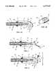
- FIG. 1AA typical embodiment of a light-guiding terminal designed to receive light from a single optical fiber is shown in FIG. 1A.
- An optical fiber 20has a core 22, a cladding 24, and a protective buffer 26.
- the end section of buffer 26is stripped at the output end of optical fiber 20, as is commonly done in standard splicing applications. In the present embodiment less then 0.5 cm of cladding 24 remains exposed.
- Terminal 34is preferably molded of glass, plastic, silica, or other appropriate light-guiding material.
- terminal 34is made of a high-purity silica material, such as that,sold under the trademark Gelsil by Geltech, Inc., of Alachua, Fla. This material is very inexpensive and easily adaptable to arbitrary shapes through heat molding.
- the walls of duct 28are profiled in the shape of two coaxial, cylindrical sections, as shown in FIG. 1B.
- the diameter of the first cylindrical section of duct 28corresponds to the diameter of optical fiber 20.
- the diameter of the second cylindrical section of duct 28corresponds to the diameter of optical fiber 20 without buffer 26.
- both cylindrical sections of duct 28are 0.5 cm long, Appropriate profiles of duct 28 permit the use of optical fibers stripped of longer or shorter buffer sections, e.g., from 0.1 mm to 5 cm, and having various cross sectional dimensions, e.g., from 0.01 mm to 1 cm and more.
- the profile of duct 28terminates in a planar input face 36.
- Input face 36serves for in-coupling a light beam 38 transmitted through optical fiber 20 into terminal 34.
- the left side of terminal 34has a tapered entrance or conical space 32 where fiber 20 enters into duct 28 of terminal 34.
- a binding agent or adhesive 30is provided inside space 32.
- For a secure coupling adhesive 30should be chosen from among epoxy-based glues, or other adhesives commonly used to bond plastics and/or glass fibers. Otherwise, securement can be ensured by bracing, thermofusion, or other techniques in the field of bonding which are not detrimental to the elements of fiber 20.
- the other end of terminal 34is shaped in the form of a light-guiding tip 40.
- Tip 40is convex and its surface is covered with a reflective coating 44.
- Appropriate choice of reflective coating 44depends on the wavelength of light to be guided.
- coating 44consists of a silver-based metallic mirror coating capable of reflecting a wide range of light wavelengths, e.g., SIFLEX-MK II manufactured by Balzers Limited Film Section, FL-9496 of Lichtenstein.
- the area of reflective coating 44 and tip 40are dimensioned so as to intercept the entire cross section of diverging light beam 38.
- terminal 34has a flat output face 42 for out-coupling of light beneath tip 40.
- a focal point F of converging light beam 38is located below face 42.
- the distance between focal point F and face 42depends upon the curvature of tip 40 and can generally vary within wide limits, e.g., from a fraction of a centimeter to several decimeters or much more, depending on intended use.
- stripped optical fiber 20is first inserted into insertion duct 28. Then adhesive 30 is poured around fiber 20 to gel inside space 32. Once solidified, adhesive 30 holds fiber 20 securely in place while the walls of insertion duct 28 mechanically support the stripped section of fiber 20. This counteracts the large mechanical stress produced by light beam 38 reflecting inside core 22 at cladding 24 at the point where buffer 26 is removed.
- light beam 38After exiting from core 22 light beam 38 arrives at planar input face 36, through which it enters light-guiding terminal 34. Inside terminal 34 beam 38 propagates toward tip 40 in a diverging path. At tip 40 reflective coating 44 causes beam 38 to be reflected downward along a converging path. That is because tip 40 is convex in shape, thus acting like a focussing mirror. Continuing on its downward path, beam 38 exits tip 40 through output face 42 and converges at focal point F.
- the distance to focal point Fwill depend on the curvature of tip 40. Since the silica of tip 40 is very inexpensive and easy to heat mold, a large assortment of terminals 34 with different focal lengths can be produced and placed at the disposal of a technician mounting optical fibers. Consequently, proper focussing is ensured by appropriate choice of prefabricated terminal 34. No additional elements, such as adjusting mirrors, lenses, or any other optical elements are necessary.
- FIG. 2illustrates an alternative embodiment of terminal 34.
- the construction and form of terminal 34are basically the same as in FIG. 1A with the exception that light-guiding tip 40' is concave.
- tip 40'has the same reflective coating 44.
- Terminal 34 shownoperates in a similar manner as the one described above, but because of its concave tip 40' it uniformly disperses light beam 38 exiting through output face 42. Again, a proper choice of curvature will ensure desired divergence of emerging beam 38.
- FIG. 3illustrates still another embodiment.
- reflective coating 44covers entire tip 40 of terminal 34 with the exception of an outlet hole 46 located in the path of light beam 38.
- Hole 46is small enough to leak a portion of light beam 38 in the form of a beam 38'.
- the diameter of hole 46can be 1 mm or less.
- a photodetector 48preferably a standard photodiode or a phototransistor, is positioned in the path of light which passes through hole 46. Photodetector 48 is connected to appropriate circuit elements, e.g., amplifiers, counters, etc. (not shown), to register light leaked through hole 46.
- Terminal 34 shown in FIG. 3functions just like the one illustrated in FIG. 1, but, in addition, passes a portion of light beam 38 through outlet hole 46.
- the light traversing hole 46impinges upon photodetector 48 and is thus detected.
- This eventis registered by an electrical circuit (not shown) to which photodetector 48 is directly hooked up.
- Such monitoringenables an operator to verify that light beam 38 is pulsed at the right frequency (this is especially useful when working with pulsed laser light), or to check other parameters of light beam 38.
- FIG. 4shows another geometrical solution of light-guiding terminal 34.
- This embodimenthas a planar light-guiding tip 40" and convex output face 42'.
- terminal 34 shown in FIG. 4is different and so is its operation. Since tip 40" is planar beam 38 first undergoes uniform reflection downward without focussing. Then, at output face 42', which is convex, beam 38 is focussed at focal point F.
- light-guiding terminal 34is oval and tip 40"' is rounded off in the shape of a bulb. There is no reflective coating. Output face 42" corresponds to the surface of tip 40"'.
- Terminal 34has a rough or frosted surface capable of scattering light beam 38. Such frosting is preferably produced by grinding or otherwise abrading the surface of terminal 34. Scattering of beam 38 can also be achieved when the surface layer of terminal 34 is doped with a suitable doping agent, such as tiny particles of silver.
- Terminal 34 with frosted surface shown in FIG. 5acts to uniformly diffuse light beam 38 by scattering. Varying degrees of surface smoothness will produce different degrees of scattering.
- FIG. 6input face 36 of terminal 34 is convex.
- Output face 42"'is flat and perpendicular to the direction of propagation of light beam 38.
- Light-guiding tip 40""is rectangular.
- a diffraction pattern 50covers output face 42"'.
- Various types of diffraction patterns 50can be produced on face 42"' by conventional methods, e.g., raking or etching.
- FIG. 7illustrates three exemplary grating patterns 50 for performing standard optical operations on light beam 38.
- terminal 34 shown in FIG. 6A different light guiding method is employed by terminal 34 shown in FIG. 6.
- Light beam 38enters terminal 34 through convex face 36'. The latter focuses beam 38 on planar output face 42"'. In exiting through face 42"', beam 38 is focussed by diffraction pattern 50 at predetermined constructive interference nodes (not shown). Of course, any diffraction pattern 50 can be provided to appropriately guide and focus beam 38.
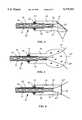
- FIG. 8shows an exemplary light-guiding terminal 34' adapted for receiving three optical fibers 20a, 20b, and 20c.
- Light-guiding tip 40""'exhibits three convex sections for deflecting and guiding diverging light beams 38a, 38b, 38c.
- Output face 42'is also convex, like in FIG. 4.
- Fibers 20a, 20b, and 20care located inside corresponding ducts 28a, 28b, 28c and they are held in place by adhesive 30 inside space 32 and mutual traction.
- other attachment methodsare possible, including placement of adhesive between individual optical fibers.
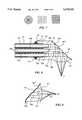
- FIG. 9is a side view of the tip portion of anther light-guiding terminal for three optical fibers (not shown).
- the curvatures of the reflecting sections of light-guiding tip 40""'are different than in the exemplary embodiment in FIG. 8.
- Output face 42'is convex.
- FIG. 10shows an exemplary integrated optical cable 66 which can be used in conjunction with light-guiding terminal 34.
- Optical cable 66includes a large-diameter power laser fiber 56 and a video fiber bundle 58 for image transmission.
- the diameter of power laser fiber 56can range from less than a few millimeters to a centimeter or more.
- Video fiber bundle 58consists of individual video fibers 20 shown in cross section in FIG. 11.
- a protective bundle collar 64surrounds bundle 58.
- Both bundle 58 and power laser fiber 56are embedded inside a light-transmitter bundle 54 consisting of individual optical fibers.
- the individual fibers of bundle 54are embedded in a bonding epoxy resin 54 and their purpose is to deliver visible light for illumination.
- Fiber alignment pins 62a and 62bare wedged in on either side of bundle 54 to align optical fibers with laser fiber 56 and video fiber bundle 58. This ensures that light carried by power laser fiber 56, the fibers of bundle 58, and the fibers of bundle 54 are focussed on the same spot by light-guiding terminal 34 of FIG. 12. The method to achieve this effect is well-know to one skilled in the art.
- cable 66is enveloped by a protective sheath 60 of plastic material.
- FIG. 12illustrates cable 66 inserted into duct 28 of light-guiding terminal 34. For reasons of clarity, only some light beams 38a, 38b, 38c, etc. are traced.
- analogous terminals 34'can also be used for multiple fibers. This is illustrated in FIG. 8, where light beams 38a, 38b, 38c of fibers 20a, 20b, and 20c enter terminal 34' through input face 30, are reflected by convex sections of tip 40""', and focussed at focal point F by convex output face 42.
- the convex sections of tip 40 of terminal 34 shown in FIG. 9focuses beams 38a, 38b, and 38c at two different foci F1 and F2.
- integrated optical cable 66(FIG. 10) can be used to perform visually supervised laser surgery with the aid of terminal 34'.
- power laser fiber 56delivers a high-energy beam 38a via terminal 34' (FIG. 12) to a focal point F coincident with the area of surgery.
- high-energy beam 38aperforms the desired incision.
- the fibers of light-transmitter bundle 52deliver light 38b to illuminate focal point F. A portion of that light 38c is reflected back towards input face 42' of terminal 34'. Reflected light 38c carries an image of surgical area F. After re-entering tip 40""' through output face 42' light 38c is reflected by reflective coating 44 to video fiber bundle 58.
- an image of focal point Fis transmitted back to the sender, where it can be projected and processed by appropriate image processing equipment (not shown).
- This light-guiding terminalcan be mounted quickly, in one easy-to-follow step, and is sufficiently inexpensive to be considered disposable.
- the light-guiding terminal of the inventionensures proper beam alignment and provides stress relief at fiber ends. There is also no need to use additional optical elements or mechanical devices with the light-guiding terminal presented.
- the geometry of the light-guiding terminalcan be altered to perform virtually any optical operation formerly requiring a large number of optical elements.
- the light-guiding tipcan exhibit several forms of curvature at once, thus treating each portion of a light beam received differently.
- diffraction gratingscan be provided at various locations on the surface of the terminal.
- the terminalcan bemused with many fibers, fiber bundles, and cables to perform multiple optical tasks simultaneously using transmitted and reflected light. The materials, dimensions, shapes, and many other parameters can be changed as well.
Landscapes
- Physics & Mathematics (AREA)
- Health & Medical Sciences (AREA)
- Surgery (AREA)
- Optics & Photonics (AREA)
- Life Sciences & Earth Sciences (AREA)
- Engineering & Computer Science (AREA)
- Molecular Biology (AREA)
- Nuclear Medicine, Radiotherapy & Molecular Imaging (AREA)
- Electromagnetism (AREA)
- Biomedical Technology (AREA)
- Heart & Thoracic Surgery (AREA)
- Medical Informatics (AREA)
- Otolaryngology (AREA)
- Animal Behavior & Ethology (AREA)
- General Health & Medical Sciences (AREA)
- Public Health (AREA)
- Veterinary Medicine (AREA)
- General Physics & Mathematics (AREA)
- Optical Couplings Of Light Guides (AREA)
Abstract
Description
______________________________________ LIST OF REFERENCE NUMBERS ______________________________________ 20 (a, b, c) optical fiber(s) 22core 24cladding 26 buffer 28 (a, b, c) insertion duct(s) 30 adhesive 32conical space 34, 34' light-guidingterminal 36, 36' input face 38 (a, b, c), 38' light beam(s) 40, 40' . . . light-guidingtip 42, 42'. . . output face 44reflective coating 46outlet hole 48photodetector 50diffraction pattern 52 light-transmitter bundle 54bonding epoxy resin 56power laser fiber 58video fiber bundle 6062a, 62b protective sheath fiber alignment pins 64protective bundle collar 66 integrated optical cable ______________________________________
Claims (9)
Priority Applications (1)
| Application Number | Priority Date | Filing Date | Title |
|---|---|---|---|
| US08/252,913US5479543A (en) | 1994-06-02 | 1994-06-02 | Precision light-guiding terminal for optical fibers |
Applications Claiming Priority (1)
| Application Number | Priority Date | Filing Date | Title |
|---|---|---|---|
| US08/252,913US5479543A (en) | 1994-06-02 | 1994-06-02 | Precision light-guiding terminal for optical fibers |
Publications (1)
| Publication Number | Publication Date |
|---|---|
| US5479543Atrue US5479543A (en) | 1995-12-26 |
Family
ID=22958074
Family Applications (1)
| Application Number | Title | Priority Date | Filing Date |
|---|---|---|---|
| US08/252,913Expired - LifetimeUS5479543A (en) | 1994-06-02 | 1994-06-02 | Precision light-guiding terminal for optical fibers |
Country Status (1)
| Country | Link |
|---|---|
| US (1) | US5479543A (en) |
Cited By (28)
| Publication number | Priority date | Publication date | Assignee | Title |
|---|---|---|---|---|
| FR2756053A1 (en)* | 1996-11-21 | 1998-05-22 | Quantel | DEVICE FOR DETECTING DAMAGE IN AN OPTICAL FIBER |
| US5909301A (en)* | 1995-06-07 | 1999-06-01 | Optical Switch Corporation | Frustrated total internal reflection device having a first spacer and a second spacer |
| US6137930A (en)* | 1998-07-08 | 2000-10-24 | Optical Switch Corporation | Method and apparatus for aligning optical fibers |
| WO2001002877A3 (en)* | 1999-06-30 | 2001-04-26 | Comview Graphics Ltd | Light sampling devices and projector system including same |
| US6236778B1 (en) | 1998-12-16 | 2001-05-22 | Optical Switch Corporation | Frustrated total internal reflection bus and method of operation |
| US6236787B1 (en) | 1998-07-08 | 2001-05-22 | Optical Switch Corporation | Method and apparatus for aligning optical fibers using an alignment spacer |
| US6243511B1 (en) | 1999-02-04 | 2001-06-05 | Optical Switch Corporation | System and method for determining the condition of an optical signal |
| US6253007B1 (en) | 1998-07-08 | 2001-06-26 | Optical Switch Corporation | Method and apparatus for connecting optical fibers |
| EP1172674A3 (en)* | 2000-07-10 | 2002-06-19 | Infineon Technologies AG | Optical fiber for optically coupling a light source to a multimode optical fiber and method of making same |
| US6418252B1 (en)* | 2001-01-16 | 2002-07-09 | The Regents Of The University Of California | Light diffusing fiber optic chamber |
| US6454791B1 (en) | 1994-03-21 | 2002-09-24 | Marvin A. Prescott | Laser therapy for foot conditions |
| US20030215207A1 (en)* | 2001-06-26 | 2003-11-20 | Derosa Michael E. | Method and device for removing heat from a fiber-optic package |
| US20040052462A1 (en)* | 2002-06-27 | 2004-03-18 | Dale Buermann | Optical fiber terminator using toroidal reflective surfaces |
| US6813418B1 (en)* | 1999-07-12 | 2004-11-02 | Harting Elektro-Optische Bauteile Gmbh & Co. Kg | Optoelectronic assembly, components for same and method for making same |
| US20070016176A1 (en)* | 2004-08-13 | 2007-01-18 | Dmitri Boutoussov | Laser handpiece architecture and methods |
| US20070208328A1 (en)* | 1995-08-31 | 2007-09-06 | Dmitri Boutoussov | Contra-angel rotating handpiece having tactile-feedback tip ferrule |
| US20080002927A1 (en)* | 2006-06-12 | 2008-01-03 | Prescient Medical, Inc. | Miniature fiber optic spectroscopy probes |
| US20090143775A1 (en)* | 1995-08-31 | 2009-06-04 | Rizoiu Ioana M | Medical laser having controlled-temperature and sterilized fluid output |
| US20090211418A1 (en)* | 2008-02-26 | 2009-08-27 | Jeffrey Cahoon | Fruit slicing system and method of use |
| US20090315816A1 (en)* | 2008-06-18 | 2009-12-24 | Samsung Electronics Co., Ltd. | Display apparatus |
| US20100151406A1 (en)* | 2004-01-08 | 2010-06-17 | Dmitri Boutoussov | Fluid conditioning system |
| DE102009047105A1 (en)* | 2009-11-25 | 2011-05-26 | Trumpf Laser Gmbh + Co. Kg | Imaging device with reflective focusing optics |
| US7952719B2 (en) | 2007-06-08 | 2011-05-31 | Prescient Medical, Inc. | Optical catheter configurations combining raman spectroscopy with optical fiber-based low coherence reflectometry |
| US8033825B2 (en) | 1995-08-31 | 2011-10-11 | Biolase Technology, Inc. | Fluid and pulsed energy output system |
| US8109981B2 (en) | 2005-01-25 | 2012-02-07 | Valam Corporation | Optical therapies and devices |
| EP2013649A4 (en)* | 2006-04-27 | 2012-11-21 | Invuity Inc | MICRO-OPTICAL ADAPTERS AND BITS FOR SURGICAL LIGHTING FIBERS |
| JP2016015979A (en)* | 2014-07-04 | 2016-02-01 | 住友電気工業株式会社 | Optical probe |
| JP2016515222A (en)* | 2013-03-14 | 2016-05-26 | カール・ツァイス・エスエムティー・ゲーエムベーハー | Optical waveguide for guiding irradiated light |
Citations (7)
| Publication number | Priority date | Publication date | Assignee | Title |
|---|---|---|---|---|
| US4068121A (en)* | 1976-05-17 | 1978-01-10 | Tally Corporation | Light collector and prism light source for photoelectric readers |
| US4883333A (en)* | 1987-10-13 | 1989-11-28 | Yanez Serge J | Integrated, solid, optical device |
| US4993796A (en)* | 1979-08-14 | 1991-02-19 | Kaptron, Inc. | Fiber optics communication modules |
| US5074632A (en)* | 1990-03-07 | 1991-12-24 | Health Research, Inc. | Fiber optic diffusers and methods for manufacture of the same |
| US5093877A (en)* | 1990-10-30 | 1992-03-03 | Advanced Cardiovascular Systems | Optical fiber lasing apparatus lens |
| US5202950A (en)* | 1990-09-27 | 1993-04-13 | Compaq Computer Corporation | Backlighting system with faceted light pipes |
| US5303324A (en)* | 1992-10-29 | 1994-04-12 | American Cyanamid Company | Method and apparatus for providing controlled light distribution from a cylindrical fiberoptic diffuser |
- 1994
- 1994-06-02USUS08/252,913patent/US5479543A/ennot_activeExpired - Lifetime
Patent Citations (7)
| Publication number | Priority date | Publication date | Assignee | Title |
|---|---|---|---|---|
| US4068121A (en)* | 1976-05-17 | 1978-01-10 | Tally Corporation | Light collector and prism light source for photoelectric readers |
| US4993796A (en)* | 1979-08-14 | 1991-02-19 | Kaptron, Inc. | Fiber optics communication modules |
| US4883333A (en)* | 1987-10-13 | 1989-11-28 | Yanez Serge J | Integrated, solid, optical device |
| US5074632A (en)* | 1990-03-07 | 1991-12-24 | Health Research, Inc. | Fiber optic diffusers and methods for manufacture of the same |
| US5202950A (en)* | 1990-09-27 | 1993-04-13 | Compaq Computer Corporation | Backlighting system with faceted light pipes |
| US5093877A (en)* | 1990-10-30 | 1992-03-03 | Advanced Cardiovascular Systems | Optical fiber lasing apparatus lens |
| US5303324A (en)* | 1992-10-29 | 1994-04-12 | American Cyanamid Company | Method and apparatus for providing controlled light distribution from a cylindrical fiberoptic diffuser |
Cited By (40)
| Publication number | Priority date | Publication date | Assignee | Title |
|---|---|---|---|---|
| US6454791B1 (en) | 1994-03-21 | 2002-09-24 | Marvin A. Prescott | Laser therapy for foot conditions |
| US5909301A (en)* | 1995-06-07 | 1999-06-01 | Optical Switch Corporation | Frustrated total internal reflection device having a first spacer and a second spacer |
| US8033825B2 (en) | 1995-08-31 | 2011-10-11 | Biolase Technology, Inc. | Fluid and pulsed energy output system |
| US20090143775A1 (en)* | 1995-08-31 | 2009-06-04 | Rizoiu Ioana M | Medical laser having controlled-temperature and sterilized fluid output |
| US20070208328A1 (en)* | 1995-08-31 | 2007-09-06 | Dmitri Boutoussov | Contra-angel rotating handpiece having tactile-feedback tip ferrule |
| EP0844472A1 (en)* | 1996-11-21 | 1998-05-27 | Quantel | Device for detecting damage in an optical fibre |
| FR2756053A1 (en)* | 1996-11-21 | 1998-05-22 | Quantel | DEVICE FOR DETECTING DAMAGE IN AN OPTICAL FIBER |
| US6137930A (en)* | 1998-07-08 | 2000-10-24 | Optical Switch Corporation | Method and apparatus for aligning optical fibers |
| US6236787B1 (en) | 1998-07-08 | 2001-05-22 | Optical Switch Corporation | Method and apparatus for aligning optical fibers using an alignment spacer |
| US6253007B1 (en) | 1998-07-08 | 2001-06-26 | Optical Switch Corporation | Method and apparatus for connecting optical fibers |
| US6236778B1 (en) | 1998-12-16 | 2001-05-22 | Optical Switch Corporation | Frustrated total internal reflection bus and method of operation |
| US6243511B1 (en) | 1999-02-04 | 2001-06-05 | Optical Switch Corporation | System and method for determining the condition of an optical signal |
| WO2001002877A3 (en)* | 1999-06-30 | 2001-04-26 | Comview Graphics Ltd | Light sampling devices and projector system including same |
| US6481856B1 (en)* | 1999-06-30 | 2002-11-19 | Comview Graphics Ltd. | Light sampling devices and projector system including same |
| US6813418B1 (en)* | 1999-07-12 | 2004-11-02 | Harting Elektro-Optische Bauteile Gmbh & Co. Kg | Optoelectronic assembly, components for same and method for making same |
| EP1172674A3 (en)* | 2000-07-10 | 2002-06-19 | Infineon Technologies AG | Optical fiber for optically coupling a light source to a multimode optical fiber and method of making same |
| US6529661B2 (en) | 2000-07-10 | 2003-03-04 | Infineon Technologies Ag | Optical fiber for optically coupling a light radiation source to a multimode optical waveguide, and method for manufacturing it |
| US6418252B1 (en)* | 2001-01-16 | 2002-07-09 | The Regents Of The University Of California | Light diffusing fiber optic chamber |
| US6860651B2 (en) | 2001-06-26 | 2005-03-01 | Derosa Michael E. | Method and device for removing heat from a fiber-optic package |
| US20030215207A1 (en)* | 2001-06-26 | 2003-11-20 | Derosa Michael E. | Method and device for removing heat from a fiber-optic package |
| US20040052462A1 (en)* | 2002-06-27 | 2004-03-18 | Dale Buermann | Optical fiber terminator using toroidal reflective surfaces |
| US20100151406A1 (en)* | 2004-01-08 | 2010-06-17 | Dmitri Boutoussov | Fluid conditioning system |
| US20070016176A1 (en)* | 2004-08-13 | 2007-01-18 | Dmitri Boutoussov | Laser handpiece architecture and methods |
| US8109981B2 (en) | 2005-01-25 | 2012-02-07 | Valam Corporation | Optical therapies and devices |
| US9429746B2 (en) | 2006-04-27 | 2016-08-30 | Invuity, Inc. | Micro-optic adapters and tips for surgical illumination fibers |
| US9229165B2 (en) | 2006-04-27 | 2016-01-05 | Invuity, Inc. | Micro-optic adapters and tips for surgical illumination fibers |
| US8594472B2 (en) | 2006-04-27 | 2013-11-26 | Invuity, Inc. | Micro-optic adapters and tips for surgical illumination fibers |
| EP2013649A4 (en)* | 2006-04-27 | 2012-11-21 | Invuity Inc | MICRO-OPTICAL ADAPTERS AND BITS FOR SURGICAL LIGHTING FIBERS |
| US20080002927A1 (en)* | 2006-06-12 | 2008-01-03 | Prescient Medical, Inc. | Miniature fiber optic spectroscopy probes |
| US7952719B2 (en) | 2007-06-08 | 2011-05-31 | Prescient Medical, Inc. | Optical catheter configurations combining raman spectroscopy with optical fiber-based low coherence reflectometry |
| US8136433B2 (en)* | 2008-02-26 | 2012-03-20 | Jeffrey Cahoon | Fruit slicing system and method of use |
| US20090211418A1 (en)* | 2008-02-26 | 2009-08-27 | Jeffrey Cahoon | Fruit slicing system and method of use |
| US8085228B2 (en)* | 2008-06-18 | 2011-12-27 | Samsung Electronics Co., Ltd. | Display apparatus |
| US20090315816A1 (en)* | 2008-06-18 | 2009-12-24 | Samsung Electronics Co., Ltd. | Display apparatus |
| DE102009047105A1 (en)* | 2009-11-25 | 2011-05-26 | Trumpf Laser Gmbh + Co. Kg | Imaging device with reflective focusing optics |
| DE102009047105B4 (en)* | 2009-11-25 | 2015-02-05 | Trumpf Laser Gmbh | Imaging device with reflective focusing optics, laser processing unit and reflective focusing mirror element |
| US8485818B2 (en) | 2009-12-04 | 2013-07-16 | Biolase, Inc. | Fluid controller |
| JP2016515222A (en)* | 2013-03-14 | 2016-05-26 | カール・ツァイス・エスエムティー・ゲーエムベーハー | Optical waveguide for guiding irradiated light |
| US10254466B2 (en) | 2013-03-14 | 2019-04-09 | Carl Zeiss Smt Gmbh | Optical waveguide for guiding illumination light |
| JP2016015979A (en)* | 2014-07-04 | 2016-02-01 | 住友電気工業株式会社 | Optical probe |
Similar Documents
| Publication | Publication Date | Title |
|---|---|---|
| US5479543A (en) | Precision light-guiding terminal for optical fibers | |
| EP0862073B1 (en) | Ferrule with a tapered optical fibre | |
| EP0192164B1 (en) | Optical coupling device | |
| US5495541A (en) | Optical delivery device with high numerical aperture curved waveguide | |
| US6157759A (en) | Optical fiber passive alignment apparatus and method therefor | |
| US5457759A (en) | Monolithic optical system and method of making same including improved coupling means between an optical fiber and a phototransducer | |
| EP0271177B1 (en) | Optical fibre coupler | |
| US6137928A (en) | Optical fiber light distribution system and method of manufacture and illumination | |
| US6738544B2 (en) | Thermally-shaped optical fiber and a method for forming the optical fiber | |
| JP3067968B2 (en) | Optical fiber interface for coupling light source and method of manufacturing the same | |
| US4212512A (en) | Fiber optic coupler for tapping into fiber optic line | |
| FR2549239A1 (en) | FIBER OPTIC COUPLER | |
| WO2000003279A1 (en) | Method and apparatus for connecting optical fibers | |
| EP1454173B1 (en) | Focusing fiber optic | |
| JPH06501565A (en) | light tap | |
| GB1558527A (en) | Optical fibre | |
| US20040156585A1 (en) | Lensed fiber for optical interconnections | |
| US20070165982A1 (en) | Expanding single-mode fiber mode field for high power applications by fusion with multi-mode fiber | |
| US6445854B1 (en) | Optical fiber having first and second reflective surfaces and method of operation | |
| US5022733A (en) | Low-reflection ball lens connector part | |
| US20030026539A1 (en) | Optical fiber having a light converging function and method of manufacturing the same | |
| EP0918238A1 (en) | Optical device for connecting a semiconductor device and a waveguide. | |
| US6496643B1 (en) | Internal termination for optical fibers | |
| US6469835B1 (en) | Optical collimator with long working distance | |
| CN109844588B (en) | Splice for stripping cladding mode light |
Legal Events
| Date | Code | Title | Description |
|---|---|---|---|
| AS | Assignment | Owner name:RELIANT TECHNOLOGIES, INC., CALIFORNIA Free format text:ASSIGNMENT OF ASSIGNORS INTEREST;ASSIGNOR:BLACK, MICHAEL;REEL/FRAME:007024/0407 Effective date:19940518 | |
| STCF | Information on status: patent grant | Free format text:PATENTED CASE | |
| REMI | Maintenance fee reminder mailed | ||
| FPAY | Fee payment | Year of fee payment:4 | |
| SULP | Surcharge for late payment | ||
| FPAY | Fee payment | Year of fee payment:8 | |
| FPAY | Fee payment | Year of fee payment:12 | |
| AS | Assignment | Owner name:SILICON VALLEY BANK, CALIFORNIA Free format text:SECURITY AGREEMENT;ASSIGNOR:RELIANT TECHNOLOGIES, LLC;REEL/FRAME:022824/0847 Effective date:20090304 Owner name:SILICON VALLEY BANK,CALIFORNIA Free format text:SECURITY AGREEMENT;ASSIGNOR:RELIANT TECHNOLOGIES, LLC;REEL/FRAME:022824/0847 Effective date:20090304 | |
| AS | Assignment | Owner name:SILICON VALLEY BANK, CALIFORNIA Free format text:SECURITY INTEREST - MEZZANINE LOAN;ASSIGNOR:RELIANT TECHNOLOGIES, LLC;REEL/FRAME:030248/0256 Effective date:20120829 | |
| AS | Assignment | Owner name:CAPITAL ROYALTY PARTNERS II ? PARALLEL FUND ?A? L. Free format text:SHORT-FORM PATENT SECURITY AGREEMENT;ASSIGNOR:RELIANT TECHNOLOGIES, LLC;REEL/FRAME:031674/0527 Effective date:20131114 Owner name:CAPITAL ROYALTY PARTNERS II L.P., TEXAS Free format text:SHORT-FORM PATENT SECURITY AGREEMENT;ASSIGNOR:RELIANT TECHNOLOGIES, LLC;REEL/FRAME:031674/0527 Effective date:20131114 Owner name:PARALLEL INVESTMENT OPPORTUNITIES PARTNERS II L.P. Free format text:SHORT-FORM PATENT SECURITY AGREEMENT;ASSIGNOR:RELIANT TECHNOLOGIES, LLC;REEL/FRAME:031674/0527 Effective date:20131114 Owner name:CAPITAL ROYALTY PARTNERS II - PARALLEL FUND "A" L. Free format text:SHORT-FORM PATENT SECURITY AGREEMENT;ASSIGNOR:RELIANT TECHNOLOGIES, LLC;REEL/FRAME:031674/0527 Effective date:20131114 | |
| AS | Assignment | Owner name:RELIANT TECHNOLOGIES, LLC, CALIFORNIA Free format text:RELEASE OF SECURITY INTEREST IN PATENTS;ASSIGNORS:CAPITAL ROYALTY PARTNERS II L.P.;CAPITAL ROYALTY PARTNERS II - PARALLEL FUND "A" L.P.;PARALLEL INVESTMENT OPPORTUNITIES PARTNERS II L.P.;REEL/FRAME:032126/0708 Effective date:20140123 | |
| AS | Assignment | Owner name:RELIANT TECHNOLOGIES, LLC, CALIFORNIA Free format text:RELEASE OF SECURITY INTEREST IN PATENTS;ASSIGNOR:SILICON VALLEY BANK;REEL/FRAME:032125/0810 Effective date:20140123 |