US5479206A - Imaging system, electronic camera, computer system for controlling said electronic camera, and methods of controlling same - Google Patents
Imaging system, electronic camera, computer system for controlling said electronic camera, and methods of controlling sameDownload PDFInfo
- Publication number
- US5479206A US5479206AUS08/012,463US1246393AUS5479206AUS 5479206 AUS5479206 AUS 5479206AUS 1246393 AUS1246393 AUS 1246393AUS 5479206 AUS5479206 AUS 5479206A
- Authority
- US
- United States
- Prior art keywords
- image
- electronic camera
- computer system
- image data
- command
- Prior art date
- Legal status (The legal status is an assumption and is not a legal conclusion. Google has not performed a legal analysis and makes no representation as to the accuracy of the status listed.)
- Expired - Lifetime
Links
- 238000003384imaging methodMethods0.000titleclaimsdescription68
- 238000000034methodMethods0.000titleclaimsdescription37
- 230000015654memoryEffects0.000claimsabstractdescription101
- 238000012545processingMethods0.000claimsdescription110
- 230000004044responseEffects0.000claimsdescription49
- 238000012546transferMethods0.000claimsdescription21
- 230000007246mechanismEffects0.000claimsdescription13
- 238000004891communicationMethods0.000claimsdescription10
- 230000005055memory storageEffects0.000claims1
- 230000005540biological transmissionEffects0.000abstractdescription35
- 230000003287optical effectEffects0.000description31
- 238000010586diagramMethods0.000description27
- 230000001276controlling effectEffects0.000description16
- 230000006870functionEffects0.000description9
- 230000008859changeEffects0.000description7
- 238000010276constructionMethods0.000description6
- 238000010304firingMethods0.000description5
- 101100021996Arabidopsis thaliana CYP97C1 geneProteins0.000description4
- 101100021997Arabidopsis thaliana CYP97A3 geneProteins0.000description3
- 230000000694effectsEffects0.000description3
- 230000008901benefitEffects0.000description2
- 230000000875corresponding effectEffects0.000description2
- 238000001514detection methodMethods0.000description2
- 238000000926separation methodMethods0.000description2
- 238000010408sweepingMethods0.000description2
- 230000000052comparative effectEffects0.000description1
- 238000012937correctionMethods0.000description1
- 230000002596correlated effectEffects0.000description1
- 238000011161developmentMethods0.000description1
- 238000005259measurementMethods0.000description1
- 238000003825pressingMethods0.000description1
- 230000002035prolonged effectEffects0.000description1
- 230000000007visual effectEffects0.000description1
Images


Classifications
- H—ELECTRICITY
- H04—ELECTRIC COMMUNICATION TECHNIQUE
- H04N—PICTORIAL COMMUNICATION, e.g. TELEVISION
- H04N1/00—Scanning, transmission or reproduction of documents or the like, e.g. facsimile transmission; Details thereof
- H04N1/00127—Connection or combination of a still picture apparatus with another apparatus, e.g. for storage, processing or transmission of still picture signals or of information associated with a still picture
- H04N1/00204—Connection or combination of a still picture apparatus with another apparatus, e.g. for storage, processing or transmission of still picture signals or of information associated with a still picture with a digital computer or a digital computer system, e.g. an internet server
- H04N1/00236—Connection or combination of a still picture apparatus with another apparatus, e.g. for storage, processing or transmission of still picture signals or of information associated with a still picture with a digital computer or a digital computer system, e.g. an internet server using an image reading or reproducing device, e.g. a facsimile reader or printer, as a local input to or local output from a computer
- H04N1/00241—Connection or combination of a still picture apparatus with another apparatus, e.g. for storage, processing or transmission of still picture signals or of information associated with a still picture with a digital computer or a digital computer system, e.g. an internet server using an image reading or reproducing device, e.g. a facsimile reader or printer, as a local input to or local output from a computer using an image reading device as a local input to a computer
- H—ELECTRICITY
- H04—ELECTRIC COMMUNICATION TECHNIQUE
- H04N—PICTORIAL COMMUNICATION, e.g. TELEVISION
- H04N1/00—Scanning, transmission or reproduction of documents or the like, e.g. facsimile transmission; Details thereof
- H04N1/00127—Connection or combination of a still picture apparatus with another apparatus, e.g. for storage, processing or transmission of still picture signals or of information associated with a still picture
- H04N1/00204—Connection or combination of a still picture apparatus with another apparatus, e.g. for storage, processing or transmission of still picture signals or of information associated with a still picture with a digital computer or a digital computer system, e.g. an internet server
- H04N1/00236—Connection or combination of a still picture apparatus with another apparatus, e.g. for storage, processing or transmission of still picture signals or of information associated with a still picture with a digital computer or a digital computer system, e.g. an internet server using an image reading or reproducing device, e.g. a facsimile reader or printer, as a local input to or local output from a computer
- H—ELECTRICITY
- H04—ELECTRIC COMMUNICATION TECHNIQUE
- H04N—PICTORIAL COMMUNICATION, e.g. TELEVISION
- H04N1/00—Scanning, transmission or reproduction of documents or the like, e.g. facsimile transmission; Details thereof
- H04N1/0035—User-machine interface; Control console
- H04N1/00405—Output means
- H04N1/00408—Display of information to the user, e.g. menus
- H04N1/0044—Display of information to the user, e.g. menus for image preview or review, e.g. to help the user position a sheet
- H—ELECTRICITY
- H04—ELECTRIC COMMUNICATION TECHNIQUE
- H04N—PICTORIAL COMMUNICATION, e.g. TELEVISION
- H04N1/00—Scanning, transmission or reproduction of documents or the like, e.g. facsimile transmission; Details thereof
- H04N1/0035—User-machine interface; Control console
- H04N1/00405—Output means
- H04N1/00482—Output means outputting a plurality of job set-up options, e.g. number of copies, paper size or resolution
- H—ELECTRICITY
- H04—ELECTRIC COMMUNICATION TECHNIQUE
- H04N—PICTORIAL COMMUNICATION, e.g. TELEVISION
- H04N1/00—Scanning, transmission or reproduction of documents or the like, e.g. facsimile transmission; Details thereof
- H04N1/21—Intermediate information storage
- H04N1/2104—Intermediate information storage for one or a few pictures
- H04N1/2112—Intermediate information storage for one or a few pictures using still video cameras
- H04N1/2137—Intermediate information storage for one or a few pictures using still video cameras with temporary storage before final recording, e.g. in a frame buffer
- H—ELECTRICITY
- H04—ELECTRIC COMMUNICATION TECHNIQUE
- H04N—PICTORIAL COMMUNICATION, e.g. TELEVISION
- H04N1/00—Scanning, transmission or reproduction of documents or the like, e.g. facsimile transmission; Details thereof
- H04N1/38—Circuits or arrangements for blanking or otherwise eliminating unwanted parts of pictures
- H—ELECTRICITY
- H04—ELECTRIC COMMUNICATION TECHNIQUE
- H04N—PICTORIAL COMMUNICATION, e.g. TELEVISION
- H04N23/00—Cameras or camera modules comprising electronic image sensors; Control thereof
- H04N23/60—Control of cameras or camera modules
- H04N23/63—Control of cameras or camera modules by using electronic viewfinders
- H04N23/631—Graphical user interfaces [GUI] specially adapted for controlling image capture or setting capture parameters
- H04N23/632—Graphical user interfaces [GUI] specially adapted for controlling image capture or setting capture parameters for displaying or modifying preview images prior to image capturing, e.g. variety of image resolutions or capturing parameters
- H—ELECTRICITY
- H04—ELECTRIC COMMUNICATION TECHNIQUE
- H04N—PICTORIAL COMMUNICATION, e.g. TELEVISION
- H04N1/00—Scanning, transmission or reproduction of documents or the like, e.g. facsimile transmission; Details thereof
- H04N1/00127—Connection or combination of a still picture apparatus with another apparatus, e.g. for storage, processing or transmission of still picture signals or of information associated with a still picture
- H04N1/00204—Connection or combination of a still picture apparatus with another apparatus, e.g. for storage, processing or transmission of still picture signals or of information associated with a still picture with a digital computer or a digital computer system, e.g. an internet server
- H—ELECTRICITY
- H04—ELECTRIC COMMUNICATION TECHNIQUE
- H04N—PICTORIAL COMMUNICATION, e.g. TELEVISION
- H04N2101/00—Still video cameras
- H—ELECTRICITY
- H04—ELECTRIC COMMUNICATION TECHNIQUE
- H04N—PICTORIAL COMMUNICATION, e.g. TELEVISION
- H04N2201/00—Indexing scheme relating to scanning, transmission or reproduction of documents or the like, and to details thereof
- H04N2201/0008—Connection or combination of a still picture apparatus with another apparatus
- H04N2201/0015—Control of image communication with the connected apparatus, e.g. signalling capability
- H—ELECTRICITY
- H04—ELECTRIC COMMUNICATION TECHNIQUE
- H04N—PICTORIAL COMMUNICATION, e.g. TELEVISION
- H04N2201/00—Indexing scheme relating to scanning, transmission or reproduction of documents or the like, and to details thereof
- H04N2201/0077—Types of the still picture apparatus
Definitions
- This inventionrelates to an imaging system, an electronic camera, a computer system for controlling the electronic camera, and a method of controlling these systems as well as the electronic camera.
- Electronic cameras for photographing a subject and outputting an analog video signal or digital image signal which represents the image of the photographed subjectinclude video cameras, still-video cameras (electronic still-video cameras), digital still-video cameras (digital electronic still-video cameras), etc.
- new mediacan be created by preserving image data, which represents the image of the subject obtained from the electronic camera, on a recording medium such as an optical disk or magnetic disk provided in a computer system, and editing the image data.
- This new mediacan be utilized in the presentation of official reports, advertisements and data, as well as in the provision of information, using visual images.
- the image data obtained by photography using the electronic cameramust be transmitted to the computer system. Since the image data generally is of great volume, transmission requires a long period of time.
- the image data representing the image of the subject photographed by the electronic camerais stored on the recording medium, determining whether the subject has been photographed properly is important. If photography is improper, it is required that photography, inclusive of resetting of the camera control parameters, be performed again.
- the setting of the camera control parameters for photographyis carried out in the electronic camera, as mentioned above. Whenever the photographic conditions are changed, the operator of the computer system is compelled to go to the location of the electronic camera to make the necessary adjustments. This is a troublesome task.
- the entirety of the image of the subject photographed by the electronic camerais not necessarily desirable for the entirety of the image of the subject photographed by the electronic camera to be always stored on the recording medium. There are cases in which only part of the photographed image of the subject is required. If only the necessary image data is cut out and stored on the recording medium, the volume of data is reduced. In addition, the image stored on the recording medium is required to be enlarged or reduced as needed.
- the imaging systembe so arranged that such operations as the operation for performing photography, the operation for communicating the image data and the operation for storing the image data on the recording medium all be implementable on the side of the computer system.
- a solid-state electronic image sensing devicesuch as a CCD has the advantage of being small in size and therefore is utilized in electronic still-video cameras and the like.
- a solid-state electronic image sensing devicemay produce an output of a spurious signal indicative of smear or the like, and flicker may occur owing to a difference in the magnitude of dark current caused by a difference in field read-out time. Consequently, in a case where the solid-state electronic image sensing device is utilized in an electronic still-video camera, it is necessary to prevent output of the spurious signal and to perform photographic processing through which the dark currents are made to coincide every field.
- the principal object of the inventionis to make it possible to rapidly transmit image data from an electronic camera to a computer system in order to verify a photographed image and store the image on a recording medium.
- Another object of the inventionis to arrange it so that image data treated so as to be suited for storage on a recording medium can be obtained from an electronic camera.
- Still another object of the inventionis to arranged it so that photography by an electronic camera as well as the setting of conditions for photography can be performed in a computer system.
- a further object of the inventionis to arranged it so that the set ting of camera control parameters such as amount of exposure and various balances in an imaging system composed of a combination of an electronic camera and computer system can be performed on the side of the computer system.
- a further object of the inventionis to arrange it so that the number of control lines for recording a subject can be reduced in an electronic still-video camera which picks up the image of the subject using a solid-state electronic image sensing device.
- An imaging systemcomprises an electronic camera, which has electronic image pick-up processing means for photographing a subject and producing image data representing an image of the photographed subject, and a computer system equipped with a display unit and an input unit and connected to the electronic camera by a communication line.
- the electronic cameraincludes an image memory for storing the image data produced by the electronic image pick-up processing means, image reducing means for reducing, at a given magnification, the image data stored in the image memory, and first response means, operative when a preview command is applied thereto from the computer system, for causing the image reducing means to reduce the image data at the given magnification and transmitting the reduced image data to the computer system.
- the computer systemincludes first command means for transmitting the preview command to the electronic camera when a preview input is applied through the input unit, and first display control means, operative when the reduced image data transmitted from the first response means of the electronic camera in response to the preview command is received, for displaying a reduced preview image represented by the reduced image data, on the display unit.
- the present inventionfurther provides a method of controlling the above-mentioned imaging system, the electronic camera and computer system which construct the imaging system, and methods of controlling the electronic camera and computer system.
- the image data representing the image of the subject picked up in the electronic camerais reduced, transmitted to the computer and displayed on the display unit when the preview command is applied to the electronic camera from the computer system. Since the amount of image data is small, transmission time can be shortened. Whether or not an acceptable image has been obtained can be judged by observing the preview image displayed.
- the electronic camerafurther comprises second response means operative when a get command containing data designating magnification of a main image as well as an area to be cut from the main image is applied to the computer system, for creating main-image data and transmitting it to the computer system, wherein the main-image data has the magnification designated with regard to the image data of the designated area.
- the computer systemincludes second command means, operative when the magnification of the main image, the designation of the area to be cut from the main image and a get input of the main image are applied through the input unit, for transmitting the get command, which contains the data designating the applied magnification and area, to the electronic camera, and second display control means, operative when the main-image data transmitted from the second response means of the electronic camera in response to the get command is received, for displaying the main image represented by this main-image data on the display unit.
- second command meansoperative when the magnification of the main image, the designation of the area to be cut from the main image and a get input of the main image are applied through the input unit, for transmitting the get command, which contains the data designating the applied magnification and area, to the electronic camera
- second display control meansoperative when the main-image data transmitted from the second response means of the electronic camera in response to the get command is received, for displaying the main image represented by this main-image data on the display unit.
- the area to be cut from the main image on the reduced preview image displayed and the magnification of the main imagecan be designated in the computer system.
- Main-image data having the designated magnification of the designated areais transmitted from the electronic camera in conformity with the designations of area and magnification and the get command.
- the main-image datacan be displayed on the display unit and stored on a recording medium.
- main-image data transmitted from the electronic camera to the computer systemis solely that within the designated area. Accordingly, the amount of data generally is small in comparison with the image data in the entire area. This is useful also in curtailing transmission time.
- the computer systemtransmits a photographic command to the electronic camera prior to the preview command.
- the electronic cameracauses the electronic image pick-up processing means to start photography of the subject in response to the photographic command.
- the shutter release of the electronic cameracan be carried out in the computer system.
- the computer systemfurther includes control-parameter command means for setting control parameters, which are for photography of the subject by the electronic image pick-up processing means of the electronic camera, in the input unit and transmitting the set control parameters to the electronic camera.
- the electronic image pick-up processing means of the electronic cameraexecutes image pick-up processing in conformity with the control parameters applied by the control-parameter command means.
- control parameters which represent the photographic conditions of the electronic cameracan be set in the computer system, all of the photographic operations in the electronic camera can be carried out by the computer system.
- An imaging systemcomprises an electronic camera, which has electronic image pick-up processing means for photographing a subject and producing image data representing an image of the photographed subject, and a computer system provided separately of the electronic camera and connected thereto by a communication line.
- the computer systemincludes control-parameter setting means for setting control parameters for photography of the subject by the electronic image pick-up processing means of the electronic camera, photographic-command input means for starting photography of the subject by the electronic image pick-up processing means of the electronic camera, transmission-command input means for commanding that the image data produced by the electronic image pick-up processing means of the electronic camera is to be transmitted, and means for transmitting, to the electronic camera, the control parameters set by the control-parameter setting means, the photographic command inputted by the photographic-command input means and the transmission command inputted by the transmission-command input means.
- the electronic cameraincludes means for adjusting operating conditions of image pick-up processing performed by the electronic image pick-up processing means, photography-start control means for performing control in such a manner that the electronic image pick-up processing means starts image pick-up processing of the image of the subject in response to the photographic command that has been transmitted from the computer system, and means for transmitting the image data, which has been produced by the electronic image pick-up processing means, to the computer system in response to the transmission command transmitted from the computer system.
- the present inventionaccording to the second aspect thereof further provides a method of controlling the above-mentioned imaging system, the electronic camera and computer system which construct the imaging system, and methods of controlling the electronic camera and computer system.
- the electronic cameralacks a shutter release switch and control-parameter setting unit operated by a human being.
- control parametersare set in the computer system and the set control parameters are transmitted to the electronic camera.
- the operating conditions conforming to the control parametersare adjusted in the electronic camera.
- control parameters which represent the photographic conditions of the electronic cameracan be set in the computer system.
- all of the photographic operations in the electronic cameracan be performed by the computer system.
- An imaging systemcomprises an electronic camera, which has electronic image pick-up processing means for photographing a subject and producing image data representing an image of the photographed subject, and a computer system capable of communicating with the electronic camera.
- the electronic image pick-up processing means of the electronic cameraincludes means for detecting a present controlled variable for photographic processing, means for controlling feedback in such a manner that the detected controlled variable will agree with a given target value, automatic control means for deciding a target value, which is based upon information obtained from the subject or set information, in an automatic control mode, and applying the decided target value to the feedback control means, and control means for starting the automatic control means when an automatic control command has been applied from the computer system, and transmitting the present controlled variable detected by the detecting means to the computer system, and thereafter applying the target value, which will be transmitted from the computer system, to the feedback control means, when a manual control command has been applied.
- the computer systemincludes means for setting one of the automatic control mode and manual control mode, means for issuing, and transmitting to the electronic camera, the automatic control command when the automatic control mode has been set and the manual control command when the manual control mode has been set, means for displaying the present controlled variable transmitted from the electronic camera in response to the manual control command when the manual control command has been issued, means for setting a target value in the manual control mode, and means for transmitting the set target value to the electronic camera.
- the present inventionaccording to the third aspect thereof further provides a method of controlling the above-mentioned imaging system, the electronic camera and computer system which construct the imaging system, and methods of controlling the electronic camera and computer system.
- the amount of exposure, white balance, black balance, focusing and amount of zoomcan be cited as camera control parameters subjected to feedback control by the automatic control means.
- the brightness of the subjectis measured.
- the value of f-stop and the shutter speed(which correspond to target values) are decided based upon the photometric value obtained by above-mentioned measurement.
- the presently prevailing f-stop value(which corresponds to the present controlled variable) is detected, and feedback control is performed in the electronic camera in such a manner that the f-stop value will attain the target f-stop value.
- the f-stop value detected by the electronic camerais transmitted to the computer system, where the value is displayed.
- the userobserves this display and is capable of setting the f-stop value, which serves as the target, in the computer system.
- the target f-stop value set in the computer systemis transmitted to the electronic camera, where the above-mentioned feedback control is executed.
- An automatic mode and a remote mode in a preferred embodiment of the inventioncorrespond to the automatic control mode and manual control mode, respectively, of the invention.
- a manual control commandis transmitted to the electronic camera when the manual control mode is set in the computer system.
- the electronic cameraresponds by transmitting the present controlled variable of a control parameter to the computer system.
- the received controlled variableis displayed in the computer system.
- the user of the imaging systemobserves the displayed controlled variable and is capable of determining whether it is necessary to change or set the target value of the control parameter.
- the present controlled variable in the cameraBy employing the present controlled variable in the camera as a reference, the user is capable of deciding the target value of the control parameter.
- the usercan set the target value of the control parameter of the electronic camera in the computer system, and the target value set in the computer system is transmitted to the electronic camera.
- the present controlled variable of the control parameteris subjected to feedback control in the electronic camera so as to be brought into agreement with the target value.
- An imaging systemcomprises an electronic camera for adjusting control parameters of an imaging optical system in conformity with a given command, photographing a subject using the imaging optical system and producing image data representing an image of the photographed subject, and a computer system capable of communicating with the electronic camera and taking the initiative in the communication with the electronic camera.
- the computer systemhas means for setting a target value relating to a control parameter of the imaging optical system, and transmitting means for transmitting the set target value to the electronic camera along with a setting command.
- the electronic cameraincludes means for periodically detecting a controlled variable relating to the control parameter of the imaging optical system, target-value memory means for storing the applied target value relating to the control parameter of the imaging optical system, means for performing feedback control in such a manner that the controlled variable detected by the detecting means will agree with a given target value, comparing means for periodically comparing the detected controlled variable relating to the imaging optical system with the stored target value, comparison-value memory means for storing results of comparison performed by the comparing means, means for transmitting, to the computer system, the results of comparison stored by the comparison-value memory means, and control means responsive to transmission of the target value along with the setting command from the computer system for performing control so as to read the results of comparison stored in the comparison-value memory means immediately before said transmission, store the target value transmitted from the computer system in the target-value memory means as a new target value if the results of comparison indicate agreement, transmit the fact of agreement to the computer system, using the transmitting means, as a response to the setting command and carry out feedback control using the feedback control means in such
- the computer systemincludes means for setting a notification mode for notifying of a present controlled variable relating to a control parameter of the imaging optical system, and transmitting means for transmitting a controlled-variable transmission command to the electronic camera when the notification mode has been set.
- the electronic camera in this embodimentincludes means for periodically detecting a controlled variable relating to the control parameter of the imaging optical system, means for storing the applied target value relating to the control parameter of the imaging optical system, comparing means for periodically comparing the detected controlled variable relating to the control parameter of the imaging optical system with the stored target value, means for transmitting to the computer system, the results of the comparison by the comparing means and the target value relating to the imaging optical system, and control means responsive to transmission of the controlled-variable transmission command from the computer system for performing control so as to read the results of comparison performed by the comparing means immediately before said transmission, and transmit to the computer system, as a response to the controlled-variable transmission command, and using the transmitting means, the controlled variable detected by the detecting means immediately before receipt of the controlled-variable transmission command if the results of comparison indicate agreement, wherein if the results of comparison indicate non-agreement, the control means performs control so as to transmit this fact to the computer system, using the transmitting means, as a response to the controlled-variable transmission command.
- the present inventionaccording to the fourth aspect thereof further provides a method of controlling the above-mentioned imaging system, the electronic camera which constructs the imaging system, and a method of controlling the electronic camera.
- a target value stored in the electronic camera and the present controlled variable detectedare compared. If the electronic camera is being controlled accurately, the target value and the detected controlled variable should agree.
- a target value set in the computer systemis transmitted to the electronic camera together with a setting command.
- the results of comparisonare read. If agreement is obtained, the memory means is rewritten and the imaging optical system is subjected to feedback control in such a manner that the newly stored target value will be attained. If the results of the comparison show agreement, this fact is transmitted to the computer system. In the case of non-agreement such fact is also transferred to the computer system.
- a notification control command set in the computer systemis transmitted to the electronic camera.
- the results of comparisonare read. If the resultsof comparison agree, the present controlled variable that has been stored is transmitted to the computer system. If the results of comparison indicate non-agreement, this fact is transmitted to the computer system.
- the target value and the controlled variableare compared, and the results of comparison are transmitted to the computer system. Accordingly, even if the operation for performing photography is carried out in the computer system, whether or not the electronic camera is being controlled correctly can be grasped with comparative ease.
- control commandsare sent solely from the computer system, control of overall operation also is made comparatively simple.
- An electronic still-video cameracomprises a solidstate electronic image sensing device for picking up an image of a subject, time setting means in which there are predetermined a first time period from a prescribed reference time following a photographic command to start of exposure, a second time period from the reference time to start of processing for erasing a spurious signal produced in the solid-state electronic image sensing device, and a third time period from the reference time to start of readout of a signal charge stored in the solid-state electronic image sensing device by photography, spurious-signal erasing means for performing erasing processing to erase a spurious signal, driving means for driving the solid-state electronic image sensing device, photographic command means for applying the photographic command, control means responsive to the photographic command applied by the photographic command means for performing control in such a manner that exposure of the solid-state electronic image sensing device is started when the first time period has elapsed from the reference time, erasing processing for erasing the spurious signal by the spurious-signal
- the present inventionfurther provides a method of controlling the above-described electronic still-video camera.
- the photographic commandis provided by the operator of the electronic still-video camera, whereupon exposure, erasure of spurious signals and signal-charge readout are performed after respective fixed time periods so that recording may be performed on the recording medium.
- exposure, processing for erasing spurious signals and signal-charge readoutare performed automatically after respective fixed time periods, and the image of the subject is recorded. Accordingly, the number of control lines for recording can be reduced.
- An electronic still-video cameracomprises a solid-state electronic image sensing device composed of a number of photoelectric transducers arranged in row and column directions, time setting means in which there are predetermined a first time period from a prescribed reference time following a recording command to start of photography for recording, a second time period from the reference time to start of processing for erasing a spurious signal produced in the solid-state electronic image sensing device, and a third time period from the reference time to start of readout of a signal charge stored in the solid-state electronic image sensing device by photography for recording, spurious-signal erasing means for performing erasing processing to erase a spurious signal, driving means for driving the solid-state electronic image sensing device, recording command means for applying the recording command, first control means for controlling the driving means in such a manner that the signal charge that has been obtained by photography of the subject using the solid-state electronic image sensing device and stored in the photoelectric transducers is read out as a first field signal with regard to the photo
- the present inventionfurther provides a method of controlling the above-described electronic still-video camera.
- the driving meansapplies a readout clock signal to the solid-state electronic image sensing device in such a manner that the signal charge stored in every other column of the photoelectric transducers in each row is read out when one frame of the video signal composed of the first and second field signals, for example, is obtained, and applies a high-speed readout clock signal to the solid-state electronic image sensing device in such a manner that the signal charge stored in all columns of the photoelectric transducers in each row is read out when one frame of the video signal composed of the first through fourth field signals is obtained.
- one frame of the video signal in which one frame is composed of the first through fourth field signalsis recorded on the recording medium when recording is performed on the recording medium. Accordingly, a video signal having a high resolution can be recorded on the recording medium.
- Erasing processing for erasing spurious signalsis a concept which covers processing for sweeping out smear charge.
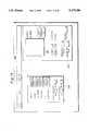
- FIG. 1is a diagram showing the overall configuration of an imaging system
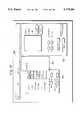
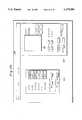
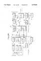
- FIG. 2is a block diagram showing the electrical construction of the imaging system
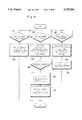
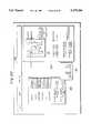
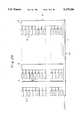
- FIG. 3is a flowchart showing a processing procedure in a host computer
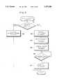
- FIG. 4is a flowchart showing a processing procedure in an electronic camera
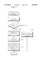
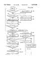
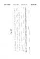
- FIG. 5is a flowchart showing part of a procedure of set-up processing
- FIG. 6is a flowchart showing the initial processing of the electronic camera
- FIG. 7is a flowchart showing a processing procedure for setting the parameters of the electronic camera
- FIG. 8is a diagram showing a plurality of display areas displayed on a display unit
- FIG. 9is a diagram showing what is displayed in some of the areas of the display unit.
- FIG. 10is a diagram illustrating an example of a display on the display unit
- FIG. 11is a diagram illustrating an example of a display on the display unit
- FIG. 12is a diagram illustrating an example of a display on the display unit
- FIG. 13is a diagram illustrating an example of a display on the display unit
- FIG. 14is a diagram illustrating an example of a display on the display unit
- FIG. 15is a diagram illustrating an example of a display on the display unit
- FIG. 16is a diagram illustrating an example of a display on the display unit
- FIG. 17is a diagram illustrating an example of a display on the display unit
- FIG. 18is a diagram illustrating an example of a display on the display unit
- FIG. 19is a diagram illustrating an example of a display on the display unit
- FIG. 20is a diagram illustrating an example of a display on the display unit
- FIG. 21is a diagram illustrating an example of a display on the display unit
- FIG. 22is a diagram illustrating an example of a display on the display unit
- FIG. 23is a diagram illustrating an example of a display on the display unit
- FIG. 24is a diagram illustrating an example of a display on the display unit
- FIG. 25is a flowchart showing part of a procedure of set-up processing
- FIG. 26is a flowchart showing processing for rewriting camera control parameters
- FIG. 27is a block diagram showing the electrical construction of an imaging system according to another embodiment of the present invention.
- FIG. 28is a block diagram showing the construction of an electronic camera
- FIG. 29is a schematic view of a CCD.
- FIG. 30is a time chart illustrating the photographic sequence of a subject.
- FIG. 1illustrates the configuration of an imaging system according to an embodiment of the present invention.
- An imaging systemincludes an electronic camera 10 which photographs a subject SU and produces image data representing the image of the subject, and a host computer 30 connected to the electronic camera 10 by a communication line.
- the electronic camera 10is a digital electronic still-video camera, by way of example.
- the electronic camera 10is not provided with a shutter release switch nor with a control-parameter setting unit for setting black balance, white balance, etc.
- a monitor display unit 5 for displaying the image of the subjectis connected to the electronic camera 10.
- the monitor display unit 5may be a viewfinder integrated with the electronic camera 10.
- a display unit 40Connected to the host computer 30 is a display unit 40 on which are displayed the image of the subject photographed using the electronic camera 10, camera control parameters, described below in detail, a capture command, etc. Also connected to the host computer 30 are a keyboard 36 and a mouse 37 serving as input units, as well as an optical disk unit 38 for recording image data.
- FIG. 2is a block diagram illustrating the electrical construction of the imaging system shown in FIG. 1.
- the photographic operation of the electronic camera 10, the treatment of the image data in the electronic camera 10 and transmission processingare under the overall supervision of a camera control unit 18, which operates based upon commands transmitted from the host computer 30.
- the electronic camera 10contains a communication interface 9 for receiving commands sent from the host computer 30 and transmitting image data to the host computer 30.
- the camera control unit 18is composed of a CPU and its periphery circuitry.
- the electronic camera 10includes an imaging optical system having a zoom-lens mechanism 11 and a diaphragm 12 for forming the image of the subject, a CCD 13 arranged at the image-forming position of the image of the subject for outputting a video signal which represents the image of the subject photographed, and a signal processing circuit 14 for obtaining an RGB signal by subjecting the video signal from the CCD 13 to color separation, white-balance adjustment, black-balance adjustment, etc.
- the electronic camera 10further includes a digital/analog (D/A) converting circuit 22 and a driver 23 for adjusting the amount of zoom of the zoom-lens mechanism 11 and controlling the diaphragm 12.
- the camera control unit 18outputs control data regarding the amount of zoom and control data for controlling the diaphragm, and the driver 23 is driven via the D/A converting circuit 22 so that the amount of zoom and the diaphragm are adjusted.
- D/Adigital/analog
- the signal processing (color separation, adjustment of white balance and black balance) in signal processing circuit 14also is carried out by the camera control unit 18.
- the electronic camera 10includes a D/A converting circuit 28 for converting the digital control data regarding signal processing outputted by the camera control unit 18 into an analog control signal and applying the analog control signal to the signal processing circuit 14.
- the electronic camera 10further includes a photometric element 20.
- a signal representing the amount of received lightis outputted by the photometric element 20.
- This signalis applied to an analog/digital (A/D) converting circuit 21, which converts the signal into digital data and applies this data to the camera control unit 18.
- A/Danalog/digital
- the data regarding the amount of received light, which data is obtained from the photometric element 20,is utilized for the control of the diaphragm and for white-balance adjustment and black-balance adjustment in the signal processing circuit 14.
- an amplifier 24 and an A/D converting circuit 25are also included in the electronic camera 10 in order that the amount of zoom and f-stop in the zoom-lens mechanism 11 may be ascertained in the camera control unit 18. Data indicative of the amount of zoom and f-stop is applied to the camera control unit 18 via the amplifier 24 and A/D converting circuit 25.
- an integrating circuit 26 and an A/D converting circuit 27in order that the amounts of white balance and black balance in the signal processing circuit 14 may be ascertained in the camera control unit 18.
- the integrating circuit 26integrates a luminance signal Y and color-difference signals R-G, B-G, which are obtained from the signal processing circuit 14, and applies the integra ted signals to the camera control unit 18 via the A/D converting circuit 27. As a result, the amounts of white balance and black balance are ascertained in the camera control unit 18.
- the amount of zoom, the f-stop value and the values of white and black balanceundergo feedback control under the control of the camera control unit 18.
- the camera control unit 18performs so-called electronic-shutter control (control of shot timing and shutter speed) in the CCD 13.
- the electronic camera 10further includes an analog/digital (A/D) converting circuit 15 for converting the RGB signal outputted by the signal processing circuit 14 into digital image data, an image memory 16 for storing the digital image data converted in the A/D converting circuit 15, a thinning-out circuit 19 for thinning out pixels represented by the image data, and a main memory 17.
- the main memory 17is provided with a transfer buffer 17A for temporarily storing image data to be transmitted to the host computer 30, a camera control-parameter memory 17B which stores camera control parameters for shutter control and adjustment of white balance and black balance, a controlled-variable memory 17C in which a presently prevailing controlled variable is stored, and a reception buffer 17D for temporarily storing camera control parameters transmitted from the host computer 30.
- the image memory 16has a capacity capable of storing at least one frame of image data.
- the electronic camera 10further includes a D/A converting circuit 29 which converts the digital image data into an analog video signal in order to display the image of the photographed subject on the monitor display unit 5.
- the host computer 30includes a CPU 31, by which the overall operation of the host computer 30 is supervised.
- the CPU 31creates various data and commands, described later, based upon input signals applied thereto from the keyboard 36 and mouse 37 connected to the host computer 30.
- the host computer 30includes a communication interface 33. Transmission of the data and commands, which have been created by the CPU 31, to the electronic camera 10, and reception of image data transmitted from the electronic camera 10, are carried out through the communication interface 33.
- the host computer 30further includes a main memory 32 and a display memory 34.
- the main memory 32is provided with a transfer buffer 32A which stores image data transmitted from the electronic camera 10, and a camera control-parameter memory 32 for storing camera control parameters, such as amount of exposure, black balance and white balance, set on the screen of the display unit 40 by the keyboard 36 or mouse 37.
- the display memory 34stores data representing the image, characters and symbols displayed on the display unit 40.
- an optical disk unit 38Connected to the host computer 30 is an optical disk unit 38, in which the image data is recorded on an optical disk.
- the host computer 30may be provided with a monitor display unit 5A which, by being connected directly to the electronic camera 10, allows the image of the subject photographed by the electronic camera 10 to be displayed on the monitor display unit 5A so that the image can be observed while the host computer 30 is being operated.
- FIGS. 3 and 4are flowcharts illustrating processing procedures for image pick-up, transmission, display and recording in this imaging system.
- FIG. 3is a flowchart showing a processing procedure in the host computer 30, and
- FIG. 4is a flowchart showing a processing procedure in the electronic camera 10.
- FIG. 5is a flowchart showing part of a procedure of set-up processing (step 62) in the host computer 30,
- FIG. 6is a flowchart showing the initial processing in the electronic camera 10, and
- FIG. 7is a flowchart showing processing (steps 81, 82) for setting or adjusting the camera control parameters in the electronic camera 10.
- FIG. 8is a diagram showing various areas set on the screen of the display unit 40.
- FIG. 9is a diagram showing an example what is displayed in some of the areas among the various areas set on the screen of the display unit 40, and
- FIGS. 10 through 24are diagrams illustrating examples of screens displayed on the display unit 40.
- Initial processingis carried out when the power supply of the electronic camera 10 is turned on.
- the electronic camera 10has an automatic function for automatically setting a controlled variable (the value of a camera control parameter) of the electronic camera 10 in the camera, a remote function for making settings in the host computer 30, and a manual function by which the operator makes settings at the electronic camera 10.
- a controlled variablethe value of a camera control parameter
- a target value of exposure to be setis decided based upon the photometric information obtained from the photometric element 20, and the diaphragm 12 is controlled in such a manner that the target value decided is obtained.
- the presently prevailing f-stop value that has been setis stored in the controlled-variable memory 17C (step 106 in FIG. 6).
- the diaphragm 12is adjusted automatically in accordance with the information obtained from the photometric element 20 (steD 109 in FIG. 6).
- An initial screenis displayed on the display unit 40 when the power supply of the host computer 30 is turned on (step 61 in FIG. 3).
- various display areasare displayed on the screen of the display unit 40 as needed.
- the areasinclude a menu display area 126, a set-up area 120, a capture-command input area 122, a preview-image display area 121, a camera control-parameter display area 124, a parameter setting area 125, and a main-image display area 123.
- a histogram window for displaying a pixel-level histogram of the preview imageis displayed on the screen of the display unit 40 when the preview image is displayed in the preview-image display area 121.
- the menu display area 126, set-up area 120, capture-command input area 122, preview-image display area 121 and camera control-parameter display area 124are displayed.
- a menu showing "File”, “Edit”, Set-Up” and the likeis displayed in the menu display area 126.
- "File”is clicked using the mouse 37 when such processing as processing for transferring data recorded on the optical disk to the main memory 32, processing for transferring data stored in the main memory 32 to the optical disk, etc., is to be executed.
- "Edit”is clicked using the mouse 37 when data recorded on the optical disk is to be read out and the image represented by this data is to be displayed in a specific area on the display screen.
- “Set-Up”is clicked using the mouse 37 when a camera control parameter is to be set.
- Set-up processing(step 62 in FIG. 3) for camera control data (controlled variables), which is started by clicking "Set-Up", will be described below with reference to FIGS. 8 through 17.
- Set-up of camera control parametersis carried out while the host computer 30 and electronic camera 10 communicate with each other.
- the set-up itemsare broadly classified as “Select” and “Adjust” items, as shown in FIG. 9.
- the "Select” itemsinclude input, flash, exposure, positive/negative and LUT (look-up table) items.
- the “Adjust” itemsinclude exposure, black-balance and white-balance items. When “Set-Up” is clicked, these items are displayed in the set-up area 120.
- “Input”is clicked when the source generating the input image data, the form of the data, etc., are selected.
- the items representing the generating source, the form, etc.are displayed.
- “Camera”(meaning the electronic camera 10) is indicated in FIG. 9 as an example of the source generating the image data.
- “Camera”is clicked when image data is to be accepted from the electronic camera 10.
- Flashis for setting whether a flash light-emsission is to be made.
- “On” and “Off”are displayed and either can be selected using the mouse 37.
- AEautomatic
- remote functionthrough which the operator sets exposure at the host computer 30
- manual functionthrough which the operator sets exposure at the electronic camera 10.
- “Pos/Neg”is for selecting whether positive photography (ordinary photography) or negative photography (photography, in which the white and black levels are reversed, suited to negative-film photography) is to be performed. When “Pos/Neg” is clicked, “Pos” and Neg” are displayed and either can be selected.
- “LUT”is for setting tone characteristics. Tone characteristics capable of being adjusted are “Default” as well as “LUT1” through “LUT5". “Default” is the most general tone characteristic, and is predetermined. "LUT1" through “LUT5" indicate types of tone characteristics which the user of this photographic system is capable of deciding at will. When “LUT” is clicked, “Default” and “LUT1” through “LUT5" are displayed and any one of them can be selected.
- Black Balanceis for adjusting black balance. By clicking "Black Balance", a screen suited to adjustment of black balance is displayed in the parameter setting area 125 on the display screen of display unit 40, and adjustment of black balance becomes possible at the host computer 30.
- White Balanceis for adjusting white balance. By clicking "White Balance", a screen suited to adjustment of white balance is displayed in the parameter setting area 125 on the display screen of display unit 40, and adjustment of white balance becomes possible at the host computer 30.
- FIG. 10illustrates an example of a display for a condition in which "Camera” has been selected with regard to “Input” in the “Select” column of the set-up items, "On” with regard to “Flash”, “Pos” with regard to “Pos/Neg”, and “LUT1” with regard to “LUT”.
- the set itemsare displayed in the camera control-parameter display area 124. Though the five items of "Select” may be set in any order, here it is assumed that "Exposure” is set last.
- the amount of exposureis adjusted by the f-stop value.
- the shutter speedis fixed. It goes without saying that an arrangement may be adopted in which shutter speed also is capable of being set.
- the present f-stop value (controlled variable) that has been stored in the controlled-variable memory 17Cis transmitted to the host computer 30 (step 113 in FIG. 7).
- the f-stop value sent from the electronic camera 10is received in the host computer 30 (step 94 in FIG. 5).
- a range of f-stop values(open f-stop value: “Open F”; fully closed f-stop value: “Closed F”) and a present f-stop value (“Present Value -- F”) are displayed in the parameter setting area 125 shown in FIG. 13.
- "Present Value -- F”which is the presently prevailing f-stop value of the diaphragm in the electronic camera 10, displays what has been transmitted from the electronic camera 10 to the host computer 30 (step 95 in FIG. 5).
- the f-stop value represented by the length of the scroll bar 125Ais displayed as the present value in the form of numerals.
- the operator clicks "OK”the f-stop value represented by the length of the scroll bar 125A at this time is set.
- the f-stop value that has been setis displayed in the camera control-parameter display region 124, as illustrated in FIG. 14.
- Set-up data regarding the set f-stop valueis transmitted to the electronic camera 10, where the data is stored in the camera control-parameter memory area 17B and the diaphragm of the camera is adjusted in such a manner that the set target value is attained (step 81, 82 in FIG. 4 and steps 114, 115 in FIG. 7).
- the AE commandis received in the electronic camera 10
- automatic control for the diaphragmis carried out (step 116 in FIG. 7). The details of processing executed in the electronic camera 10 will be described later.
- the parameter setting area 125has a "Cancel" display as well (see FIG. 13). Clicking this allows the set f-stop value to be canceled.
- Adjustment of black balanceis carried out with regard to red and blue.
- Remote control of black balanceis set by clicking "Red” or “Blue” displayed in the parameter setting area 124.
- a remote commandis transmitted to the electronic camera 10 (step 93 in FIG. 5).
- step 111, 112 in FIG. 7When the remote command is received in the electronic camera 10 (steps 111, 112 in FIG. 7), set values of black balance (the present controlled variable) that have been stored in the controlled-variable memory 17C are read out of this memory and sent to the host computer 30 (step 113 in FIG. 7).
- the set values of black balance sent from the electronic camera 10are received and displayed by host computer 30 (steps 94, 95 in FIG. 5).
- the set valuesare displayed in the camera controlled-variable display area 124, by way of example.
- the operatorobserves the present set values of black balance displayed and adjusts the black balance when a change is deemed necessary.
- adjustment of black balanceis carried out by manipulating the mouse 37 to adjust the lengths of scroll bars 125R, 125B (the lengths of the shaded portions) in such a manner that the desired values are attained.
- the set values regarding red and blue represented by the lengths of the scroll bars 125R, 125B, respectively,are displayed in the form of numerals.
- the set values of black balanceare received in the electronic camera 10 and black balance is adjusted in accordance with the target values that have been set (steps 81, 82 in FIG. 4 and steps 114, 115 in FIG. 7).
- the parameter setting area 125includes a "Cancel" display as well.
- the set values of black balanceare displayed in the camera control-parameter display area 124, as illustrated in FIG. 17. Adjustment of white balance is performed in the same manner as adjustment of black balance.
- An “Automatic” displayis included in the parameter setting area 125 so that automatic adjustment can be selected with regard to adjustment of white balance as well, just as in the case of adjustment of black balance.
- this factis transmitted from the host computer 30 to the electronic camera 10 (steps 91, 92 in FIG. 5).
- Adjustment of white balanceis carried out with regard to red and blue.
- Remote control of white balanceis set by clicking "Red” or “Blue” displayed in the parameter setting area 124.
- a remote commandis transmitted to the electronic camera 10 (step 93 in FIG. 5).
- step 111, 112 in FIG. 7When the remote command is received in the electronic camera 10 (steps 111, 112 in FIG. 7), set values of white balance (the present controlled variable) that have been stored in the controlled-variable memory 17C are read out of this memory and sent to the host computer 30 (step 113 in FIG. 7).
- the set values of white balance sent from the electronic camera 10are displayed by host computer 30.
- the operatorobserves the set values of white balance displayed and adjusts the white balance when a change is deemed necessary (steps 94, 95 and 96 in FIG. 5.
- Adjustment of white balanceis carried out by manipulating the mouse 37 to adjust the lengths of scroll bars 125R, 125B to the desired lengths.
- the set values regarding red and blue represented by the lengths of the scroll bars 125R, 125B, respectively,are displayed in the form of numerals.
- photographic control of the electronic camera 10is carried out in response to commands from the host computer 30.
- All of the camera control data set in the set-up modeis displayed in the camera control-parameter display area 124, as shown in FIG. 20.
- This datais stored in the camera control-parameter memory 32B of the main memory 32 in the host computer 30 and in the reception buffer 17D of the main memory 17 in the electronic camera 10, after which the data is stored in the camera control-parameter memory 17B of the main memory 17.
- adjustmentis performed based upon the camera control parameters when the parameters stored in the camera control-parameter memory 17B and the parameters stored in the controlled-variable memory 17C coincide. This adjustment will be described later in greater detail.
- Lens position and zoom magnification, etc., for the purpose of focusingmay also be stored in the camera control-parameter memory 32B, and these may be read out of the controlled-variable memory 17C, transmitted to the host computer 30 and displayed thereby when remote operation is performed.
- the capture-command input area 122will be described next.
- the capture-command input area 122displays "Input”, “Frame”, “Shot”, “Get”, “Window”, “File”, “X”, “Y”, “W”, “H”, “Remaining Capacity”, “Amount of Data” and “Magnification”.
- the preview-image display area 121displays the image of the subject being photographed by the electronic camera 10.
- “Input” and “Frame”are for selecting from where a video signal representing the image displayed on the monitor display unit 5 will be obtained.
- the video signal obtained from the CCD 13is applied directly to the monitor display unit 5 via the signal processing circuit 14 without being passed through the image memory 16.
- the CCD 13is capable of being changed over selectively between ordinary NTSC drive (640 ⁇ 480 pixels) and high-definition (often referred to as "high-vision") drive (1280 ⁇ 960 pixels). Since monitor display unit 5 is operated at the NTSC rate, the CCD 13 is subjected to NTSC drive in the "Input" mode.
- the image data that has been stored in the image memory 16is applied to the monitor display unit 5 through the D/A converting circuit 29 and the image represented by this image data is displayed.
- a changeover circuit 6 controlled by the camera control unit 18is provided.
- a black dotis displayed alongside "Frame” and indicates that the "Frame” mode has been set.
- the processing of steps 83 ⁇ 90 shown in FIG. 4also indicates operation in the "Frame” mode.
- “Shot”is for applying a command which causes the electronic camera 10 to photograph the subject and transmit the image data obtained by such photography to the host computer 30 upon thinning out the data.
- the image data obtained by photography using the electronic camera 10 in response to clicking of "Shot”is stored temporarily in the image memory 16, the image data is reduced to 1/8 in each of the horizontal and vertical directions, as will be described later, and the resulting data is transmitted to the host computer 30, where the data is displayed in the preview-image display area 121 as a preview image.
- Photography of the subjectis carried out by high-definition drive of the CCD 13.
- the "Frame" modeis established automatically and the image represented by the image data that has been stored in the image memory 16 is displayed on the monitor display unit 5.
- the histogram window 127which represents a pixel-level histogram of the preview image, is displayed on the screen of the display unit 40. Since a color-level distribution of the preview image is displayed in the histogram window 127, this can be utilized in the setting of optimum photographic conditions.
- Window and “File”are for designating the destination of the image data to be accepted in accordance with the "Get" command.
- WindowWhen “Window” is clicked, the image data transmitted from the electronic camera 10 is stored in transfer buffer 32A of the main memory 32, and the image represented by this image data is displayed in the main-image display area 123 of the display unit 40.
- "File”When “File” is clicked, the image data transmitted from the electronic camera 10 is stored in the transfer buffer 32A of the main memory 32, after which the image data is stored on the optical disk by the optical disk unit 38 while being subjected to processing as necessary.
- "X”, “Y”, “W” and “H”are for designating, on the preview image, the image area to be accepted in accordance with the "Get" command.
- "X” and “Y”represent X and Y coordinates of one corner of a designation zone (indicated by the dashed line in FIG. 22)
- "W”represents the width of the designation zone
- “H”represents the height of the designation zone.
- the desired areacan be designated by inputting the values of "X", "Y”, “W” and “H” using the mouse 37.
- Magnificationis for selecting the resolution of the image to be accepted in accordance with the "Get" command.
- any of magnifications 1 ⁇ , 0.5 ⁇ , 0.25 ⁇ , 0.125 ⁇can be selected by the mouse 37.
- the enlargement ratio in the zoom-lens mechanism 11is capable of being set or manually adjusted in the host computer 30, it is possible for the magnification of photography to be made a value which exceeds 1 ⁇ .
- a value which exceeds 1 ⁇is set as the magnification only when the operator enlarges the zoom-lens mechanism 11 of the electronic camera 10 by a manual operation.
- Remaining Capacityindicates the remaining body of the transfer buffer 32A in the main memory 32 of host computer 30.
- Amount of Dataindicates the amount of image data transmit ted from the electronic camera 10 in response to the "Get" command.
- FIGS. 3 and 4will be referred to again to systematically describe the processing executed, in response to inputs of various commands from the capture-command input area 122 of the host computer 30, for imaging the subject at the electronic camera 10, transmitting the image data obtained by imaging to the host computer 30 and displaying the image data on the display unit 40.
- step 62 in FIG. 3the host computer 30 waits for clicking of "Shot" (step 63 in FIG. 3) or waits for designation of the designation zone, magnification and destination for acceptance of the image data resulting from photography (step 68 in FIG. 3).
- a shot commandis created by the CPU 31 (step 64 in FIG. 3).
- the shot command createdis transmitted to the electronic camera 10.
- the preview commandis a command for transmitting the image data, which is obtained by photography, upon reducing the data (to 1/8 uniformly according to this embodiment). This command is sent to the electronic camera 10.
- the image data obtained by imaging and processingis stored in the image memory 16 (step 84 in FIG. 4).
- the frame modeis established if the input mode is in effect.
- the image data that has been stored in the image memory 16is read out and applied to the thinning-out circuit 19.
- the image datais thinned out to uniformly to 1/8 (i.e., one pixel is extracted from eight pixels) so as to obtained image data composed of 160 pixels in the horizontal direction and 120 pixels in the vertical direction.
- the image data that has been thinned outis applied to, and temporarily stored in, the transfer buffer 17A from the thinning-out circuit 19 (step 86 in FIG. 4).
- the image data temporarily stored in the transfer buffer 17Ais transmitted to the host computer 30.
- this preview image datais temporarily stored in the transfer buffer 32A (step 66 in FIG. 3).
- the image data that has been stored in the transfer buffer 32Ais read out of the transfer buffer 32A and applied to the display memory 34, and the preview image represented by this image data is displayed in the preview-image display area 121 (step 67 in FIG. 3).
- An example of the preview image displayed in the preview-image display area 121is illustrated in FIG. 21.
- One frame of image datais composed of 1280 ⁇ 960 pixels (1228 kilobytes in case of one byte per pixel, and three times this number of kilobytes in case of color photography), as mentioned earlier, and therefore the amount of data is very large. Consequently, transmission of this data requires a long period of time.
- the preview image datathe data is reduced to 1/8 in the horizontal and vertical directions and then sent from the electronic camera 10 to the host computer 30, as set forth above. The transmission time for this data, therefore, can be shortened.
- the operatordesignates, on the preview image, the area of the image to be accepted, the magnification and the destination for acceptance, as shown in FIG. 22 (YES at step 68 in FIG. 3).
- the operator clicks "Get”YES at step 69 in FIG. 3.
- the get commandwhich includes the designated area and the magnification, is created, and this is sent to the electronic camera 10 (step 70 in FIG. 3).
- the operatorWhen an enlarged image is desired, the operator is capable of manually operating the zoom-lens mechanism 11 of the electronic camera 10 to set the mechanism to the desired magnification, as mentioned above. In this case, the operator clicks "Shot" again to repeat the photographing and previewing of the subject.
- the image data of the designated areais read out of the image memory 16.
- the image data read out of the image memory 16is applied to the thinning-out circuit 19, where thinning-out in conformity with the set magnification is performed.
- the image datais temporarily stored in the transfer buffer 17A (step 89 in FIG. 4)
- the image datais sent to the host computer 30 (step 90 in FIG. 4).
- the image data transmitted from the electronic camera 10is received in the host computer 30 (step 71 in FIG. 3).
- the image datais transferred to the destination for acceptance designated previously. Specifically, if the destination is "Window" (the main memory), the received image data is stored in the transfer buffer 32A of main memory 32 and the image represented by this image data is displayed in the main-image display area 123 of the display unit 40, as illustrated in FIG. 23 (step 73 in FIG. 3).
- the destinationis "File”
- the received image datais temporarily stored in the main memory 32, after which it is subjected to processing as necessary and transferred to the optical disk unit 38, where the image data is stored (step 75 in FIG. 3). At this time the image is not displayed in the main-image display area 123 (see FIG. 24), but an arrangement may be adopted in which the image is displayed.
- the operatormay click "File” after designating "Window” as the destination for acceptance and observing the image of the subject displayed in the main-image display area 123.
- the image data that has been stored in the main memory 32is recorded on the optical disk (YES at step 74, followed by step 75, in FIG. 3).
- operation from the "Shot” command onwardmay be done over without clicking "File”.
- the operatorSince the remaining capacity of main memory 32 and the amount of image data that has been sent are being displayed in the capture-command input area 122, the operator is capable of inputting the various commands mentioned above while observing these quantities.
- an arrangementis adopted in which input of the "Get" command is forbidden when the remaining capacity of the main memory 32 is less than the amount of image data that will be sent from the electronic camera 10.
- FIG. 25blocks whose processing is identical with the processing shown in FIG. 5 have reference numerals corresponding to the blocks in FIG. 5 enclosed in parentheses.
- FIG. 26also, blocks whose processing is identical with the processing shown in FIG. 7 have reference numerals corresponding to the blocks in FIG. 7 enclosed in parentheses.
- the processing shown in FIGS. 25 and 26may be positioned in another form without necessarily being correlated to the processing of FIGS. 5 and 7.
- step 131 in FIG. 26After the power supply of the electronic camera 10 has been turned on, it is determined whether photography is in progress (step 131 in FIG. 26). If it is determined that photography is not in progress, then it is determined whether the zoom-lens mechanism 11 and the diaphragm 12 installed in the electronic camera 10 are capable of being remotely controlled (step 133).
- the zoom-lens mechanism 11 and diaphragm 12are remotely controllable, the presently prevailing f-stop value is detected (step 134).
- the detected f-stop valueis applied to the main memory 17 and stored in the controlled-variable memory 17C as a new f-stop value (step 135).
- the zoom-lens mechanism 11 and diaphragm 12 installed in the electronic camera 10are not capable of being remotely controlled, the fact that remote control is impossible is stored in the controlled-variable memory 17C (step 136).
- the values of white balance and black balancealso are detected and stored in the controlled-variable memory 17C. It is not always necessary to detect these values.
- the above-mentioned processingis not executed until the vertical retrace interval is attained (step 132).
- the detection of the f-stop value of the diaphragm 12is performed periodically unless photography of a subject is in progress. If photography is in progress, detection of the f-stop value is performed in every vertical retrace interval.
- the f-stop value of the diaphragm 12is stored in the controlled-variable memory 17C as new data at all times. If necessary, the other controlled variables such as the values of white balance and black balance also are stored in the controlled-variable memory 17C as new data at all times.
- Transmissions from the host computer 30 to the electronic camera 10are of two types, namely transmission of set-up data and transmission of controlled-variable transmission commands.
- Transmission of set-up datais processing for transmitting camera control parameters that have been set up, as described earlier.
- Transmission of a controlled-variable transmission commandis processing for transmitting a command which causes the presently prevailing controlled variable in the electronic camera 10 to be transmitted to the host computer 30.
- a notification modeis designated using the keyboard 36.
- a controlled-variable transmission commandis created in the CPU 31.
- the created controlled-variable transmission commandis transmitted to the electronic camera 10. The same is true also in a case where the above-described "Remote" mode has been set.
- Each section of the electronic camera 10is subjected to feedback control in conformity with the camera control parameter stored in the camera control-parameter memory 17B, and the detected controlled variable is stored in the controlled-variable memory 17C.
- the present controlled variable that has been stored in the controlled-variable memory 17C and the camera control parameter that has been stored in the camera cOntrol-parameter memory 17Bshould originally agree. However, the two will not agree if the imaging optical system which includes the diaphragm 12 is shifted after storage of the parameter in the camera control-parameter memory 17B and control of the diaphragm 12, or when an imaging optical system having different control parameters has been installed in the electronic camera 10.
- the present controlled variablef-stop value, black balance, white balance, etc.
- the camera control parameterthat has been set in the camera control-parameter memory 17B are compared periodically (step 137).
- step 138If data or a control command is not sent from the host computer 30, the program returns to step 131 (step 138).
- step 146When there is a transmission from the host computer 30, the content thereof is analyzed in the electronic camera 10 (steps 138, 139). When a controlled-variable transmission command has been received, the results of the comparison performed immediately prior to receipt of this command are read (step 146).
- controlled variable that has been stored in the controlled-variable memory 17Cis transmitted to the host computer 30 (steps 147, 148).
- controlled variables of the electronic camera 10are transmitted to the host computer 30 only in response to the transmission control command from the host computer 30.
- the camera control parameters sent from the electronic camera 10are received (step 122 in FIG. 25) and the contents of the camera control parameters are displayed on the display unit 40 (step 123).
- Set-up processingis executed with regard to any of the displayed camera control parameters that require to be set or changed.
- the results of comparing the controlled variable stored in the controlled-variable memory 17C and the camera control parameter stored in the camera control-parameter memory 17Bare read also when set-up data such as the f-stop value, black-balance value and white-balance value, etc., set as described above have been transmitted to the electronic camera 10 (steps 139, 140). With regard to the values of black and white balance, however, comparison and reading of the results thereof are not always required.
- the set-up data sent from the host computer 30is temporarily stored in the reception buffer 17D.
- step 141If, as a result of the comparison, it is found that the camera control parameter and the controlled variable that have been stored in the memories 17B and 17C, respectively, do not agree (step 141), it can be determined that control based upon the camera control parameter that has been sent from the host computer 30 is not capable of being achieved properly. In case of non-agreement, therefore, this fact is transmitted to the host computer 30 (step 149). As a result, it can be determined on the side of the host computer 30 that the imaging optical system has been exchanged for other, by way of example.
- controlis performed in such a manner that this parameter will become the set target value (step 145).
- FIG. 27is a block diagram showing the electrical construction of an imaging system according to another embodiment of the invention. Elements identical with those shown in FIG. 2 are designated by like reference characters and need not be described again.
- the imaging system shown in FIG. 27differs from that of FIG. 2 in that the display unit 40, the keyboard 36 and the mouse are connected to the electronic camera, which is designated at 10A.
- the electronic camera 10Ais capable of communicating with a host computer 30A, which is capable of recording image data on a magnetic disk 39A and an optical disk 39B, via a communication interface 9A.
- the camera control parameters that have been set using the display unit 40 and the keyboard 36 or mouse 37are stored directly in the camera control-parameter memory 17B.
- the presently prevailing set controlled variablesare read out of the controlled-variable memory 17C and displayed on the display unit 40. If necessary, controlled variables may be changed.
- the image data obtained by imagingis not sent to the host computer 30A but is instead applied to the display unit 40, where the preview image and main image are displayed. Only image data having the desired magnification and lying in the required area is transmitted to the host computer 30A and recorded on the magnetic disk 39A or optical disk 39B or stored in the transfer buffer 17A of the main memory 17 in the electronic camera 10A.
- FIGS. 28 through 30illustrate the details of the electronic camera 10, especially a series of photographic operations.
- FIG. 28is a block diagram showing the details of the electrical construction of the electronic camera 10
- FIG. 29is a schematic view of the CCD
- FIG. 30is a time chart of operation when the electronic camera 10 images a subject.
- the amount of exposureis adjusted by the f-stop value and shutter speed.
- the electronic camera 10can be divided into a camera head 49 and a camera controller 59. By thus dividing the electronic camera 10, the electronic camera is made one of the type having a separable head.
- the camera head 49includes a timing pulse generator 44 for generating horizontal (H) driving pulses and vertical (V) driving pulses at a predetermined timing.
- the camera head 49includes also a PLL circuit 43.
- the timing pulse generator 44operates based upon a horizontal retrace signal (HD) and a vertical retrace signal (VD) provided by the PLL circuit 43.
- a strobe-flash unit 48also has firing of the flash controlled by the timing pulse generator 44.
- the camera head 49includes an H driver 45 and a V driver 46 in order to read out the signal charge from the CCD 12.
- the H driving pulsesare inputted to the H driver 45, which outputs horizontal transfer pulses ⁇ H.
- the V driving pulsesare inputted to the V driver 46, which outputs vertical horizontal transfer pulses ⁇ V.
- the camera head 49further includes a preamplifier circuit 41 and a driver 42 for amplifying the signal outputted by the CCD 12.
- the camera head 49includes a power-supply circuit 47, which supplies each of the circuits with operating voltage.
- the camera con troller 59includes a timing control unit 55 for generating recording timing, and a timing pulse generator 56 which provides the PLL circuit 43 with signals such as a horizontal retrace signal and a vertical retrace signal.
- the timing control unit 55outputs a trigger signal TRG, which serves as a reference for recording timing, a mode-change signal M.C., and field-index signals FI, 2FI. All of these signals are applied to the timing pulse generator 44.
- the mode-change signal M.C.is a signal which changes over between an instance in which one frame is constructed by two field signals and an instance in which one frame is constructed by four field signals, as will be described below.
- the field index signal FIis a signal used in identifying a field signal when one frame is constructed by two field signals.
- the field index signal 2FTis a signal used in identifying a leading field signal when one frame is constructed by four field signals.
- the field index signals FI and 2FIcan be created from the vertical retrace signal VD, they need not necessarily be created in the timing control unit 55.
- the camera controller 59further includes a signal processing circuit 14, an A/D converting circuit 15, a memory-controller/memory unit 53, a D/A converting circuit 16 and a power-supply circuit 57.
- the signal processing circuit 14,which includes a color-balance circuit 51 and a gamma processing circuit 52, executes the above-described white balance and black balance processing, as well as gamma-correction processing.
- the camera controller 59is provided with a recording switch 58.
- the recording switch 58is turned on (closed) when image data of a subject is to be recorded on the optical disk. This is realized by the keyboard 36 and mouse 37 in FIG. 2. Turning on the switch 58 is equivalent to turn-on by clicking "Shot" using the mouse.
- the PLL circuit 43, timing-pulse generating circuit 44, timing control unit 55 and timing pulse generator 56are included in the camera control unit 18 in FIG. 2, and the memory-controller/memory unit 53 is constructed by part of the camera control unit 18 and the image memory 16.
- the preamplifier circuit 41, driver 42, H driver 45, V driver 46 and power-supply circuit 47are not shown in FIG. 2. Furthermore, the main memory 17, thinning-out circuit 19 and communication interface 9 are not illustrated in FIG. 28.
- the CCD 12comprises a number of photodiodes 2 arrayed in row and column directions.
- the CCD 12further includes vertical transfer lines 3, which are arranged contiguous to the photodiodes 2 in the column direction, for vertically transferring the signal charge that has accumulated in the photodiodes 2, and a horizontal transfer line 7 for horizontally transferring the signal charge.
- the method through which the signal charge stored in the photodiodes 2 of the CCD 12 of the electronic camera 10 when recording is being performeddiffers from that when recording is not being performed.
- a field signal represented by the signal charge stored in the photodiodes 2 of a (4n+1)-th row(where n is 0 or a positive integer) is treated as a first field signal
- a field signal represented by the signal charge stored in the photodiodes 2 of a (4n+3)-th rowis treated as a second field signal
- one frameis constructed by these first and second field signals.
- a field signal represented by the signal charge stored in the photodiodes 2 of a (4n+1)-th rowis treated as a first field signal
- a field signal represented by the signal charge stored in the photodiodes 2 of a (4n +2)-th rowis treated as a second field signal
- a field signal represented by the signal charge stored in the photodiodes 2 of a (4n+3)-th rowis treated as a third field signal
- a field signal represented by the signal charge stored in the photodiodes 2 of a (4n+4)-th rowis treated as a fourth field signal
- one frameis constructed by these first through fourth field signals.
- the timing generator 44operates in such a manner that the output timings of the horizontal transfer pulses ⁇ H and vertical transfer pulses ⁇ V at the time of recording also differ from those when recording is not being performed. At the time of recording, the horizontal transfer pulses ⁇ H outputted are twice the number outputted when recording is not being performed.
- Sweep-out of smear charge and level matching of dark currents field by fieldare carried out in the electronic camera 10.
- the time period from rise of the vertical retrace signal VD after issuance of a photographic command to firing of the flash, the time period from rise of the vertical retrace signal VD to sweep-out of smear charge, and the time period from the vertical retrace signal VD to readout of the signal chargeare predetermined using the keyboard 36 and mouse 37.
- the readout time of the signal chargeis decided in such a manner that the readout time of each field signal will become a whole-number multiple of 4 V (where 1 V represents one vertical retrace interval), so that the quantity of stored signal charge due to dark current will not differ from field to field.
- the time from the photographic command to firing of the strobe, the time from the photographic command to sweep-out of smear charge, and the time from the photographic command to readout of the signal chargeare stipulated in accordance with respective ones of the aforesaid predetermined times.
- the shutter 8is open until the recording switch 58 is pressed or until "Shot" is clicked. Photography and readout of the signal charge are repeated at an interval that is twice the vertical retrace interval. At this time, one frame is constructed by the first field signal and the second field signal, and the frame is displayed on the monitor display unit 5.
- the trigger signal TRGis outputted by the timing control unit 55 in synchronization with the first vertical retrace signal VD that follows the pressing or clicking operation.
- the trigger signal TRGis outputted, a mode change is performed in such a manner that one frame will be constructed by the first through fourth field signals.
- the flash 48is fired to effect exposure after sweep-out of unnecessary electric charge from the CCD 12 is performed following a predetermined fixed period of time after generation of the trigger signal TRG.
- the shutter 8is subsequently closed fully and sweep-out of the smear charge is performed.
- the signal chargeis read out and writing of the image data in the memory 53 is performed for a time equivalent to 4 V.
- the trigger signal TRGdecays, the shutter 8 is opened again and one frame is constructed by the first field signal and second field signal.
- firing of the strobe, exposure, sweep-out of smear charge, readout of signal charge and recordingare controlled.
- the number of control linescan be reduced in comparison with the prior art, in which firing of the strobe, exposure, sweep-out of smear charge, readout of signal charge and recording are controlled independently of one another.
Landscapes
- Engineering & Computer Science (AREA)
- Multimedia (AREA)
- Signal Processing (AREA)
- General Engineering & Computer Science (AREA)
- Human Computer Interaction (AREA)
- Computing Systems (AREA)
- Studio Devices (AREA)
Abstract
Description
Claims (36)
Applications Claiming Priority (10)
| Application Number | Priority Date | Filing Date | Title |
|---|---|---|---|
| JP4047628AJP2974489B2 (en) | 1992-02-04 | 1992-02-04 | Imaging system, electronic camera, computer system for controlling electronic camera, and control method thereof |
| JP04762792AJP3203263B2 (en) | 1992-02-04 | 1992-02-04 | Imaging system, electronic camera and control method thereof |
| JP4-047629 | 1992-02-04 | ||
| JP4-047627 | 1992-02-04 | ||
| JP4-047626 | 1992-02-04 | ||
| JP4-047628 | 1992-02-04 | ||
| JP4047626AJP2948974B2 (en) | 1992-02-04 | 1992-02-04 | Imaging system, electronic camera, computer system for controlling electronic camera, and control method thereof |
| JP04762992AJP3178548B2 (en) | 1992-02-04 | 1992-02-04 | Imaging system, electronic camera, computer system for controlling electronic camera, and control method thereof |
| JP4-085001 | 1992-03-09 | ||
| JP4085001AJPH05260398A (en) | 1992-03-09 | 1992-03-09 | Electronic still camera and its control method |
Publications (1)
| Publication Number | Publication Date |
|---|---|
| US5479206Atrue US5479206A (en) | 1995-12-26 |
Family
ID=27522652
Family Applications (1)
| Application Number | Title | Priority Date | Filing Date |
|---|---|---|---|
| US08/012,463Expired - LifetimeUS5479206A (en) | 1992-02-04 | 1993-02-02 | Imaging system, electronic camera, computer system for controlling said electronic camera, and methods of controlling same |
Country Status (1)
| Country | Link |
|---|---|
| US (1) | US5479206A (en) |
Cited By (125)
| Publication number | Priority date | Publication date | Assignee | Title |
|---|---|---|---|---|
| US5602412A (en)* | 1994-08-15 | 1997-02-11 | Nikon Corporation | Imaging device which adjusts the ratio of color excitation values produced by an image pickup element in accordance with an exit pupil position and the size of an aperture |
| WO1997040621A1 (en)* | 1996-04-23 | 1997-10-30 | Silicon Vision, Inc. | A digital video camera system |
| EP0750417A3 (en)* | 1995-06-23 | 1998-02-11 | Fuji Photo Film Co., Ltd. | Control method for microfilm image reader |
| EP0766460A3 (en)* | 1995-09-29 | 1998-05-20 | Konica Corporation | Video camera for image data transmission |
| FR2765437A1 (en)* | 1997-06-30 | 1998-12-31 | Samsung Aerospace Ind | DIGITAL CAMERA CAPABLE OF TRANSMITTING AUDIO DATA AND IMAGE DATA TO / FROM A REMOTE SITE |
| US5870139A (en)* | 1995-08-28 | 1999-02-09 | Ultrak, Inc. | Method and system for video multiplexing |
| US5903308A (en)* | 1996-08-26 | 1999-05-11 | Ultrak, Inc. | Phase compensation for video cameras |
| EP0858214A3 (en)* | 1997-02-07 | 1999-07-14 | Canon Kabushiki Kaisha | Video input apparatus and image pickup system including the apparatus |
| US5926208A (en)* | 1992-02-19 | 1999-07-20 | Noonen; Michael | Video compression and decompression arrangement having reconfigurable camera and low-bandwidth transmission capability |
| US5929904A (en)* | 1995-04-07 | 1999-07-27 | Canon Kabushiki Kaisha | Control of camera sensing direction in a viewable range defined by camera panning and tilting |
| US5938717A (en)* | 1996-03-04 | 1999-08-17 | Laser Technology, Inc. | Speed detection and image capture system for moving vehicles |
| US5959669A (en)* | 1993-12-31 | 1999-09-28 | Canon Kabushiki Kaisha | Image pickup apparatus having standard-resolution and high-resolution photographing modes |
| US5995140A (en)* | 1995-08-28 | 1999-11-30 | Ultrak, Inc. | System and method for synchronization of multiple video cameras |
| US6008867A (en)* | 1996-08-26 | 1999-12-28 | Ultrak, Inc. | Apparatus for control of multiplexed video system |
| US6008837A (en)* | 1995-10-05 | 1999-12-28 | Canon Kabushiki Kaisha | Camera control apparatus and method |
| US6025874A (en)* | 1995-07-11 | 2000-02-15 | Ultrak, Inc. | Video multiplexer |
| EP0862335A3 (en)* | 1997-02-28 | 2000-05-03 | Hewlett-Packard Company | Automatic color adjustment on host for strobe usage on a digital camera |
| US6061092A (en)* | 1997-12-05 | 2000-05-09 | Intel Corporation | Method and apparatus for dark frame cancellation for CMOS sensor-based tethered video peripherals |
| WO2000031614A1 (en)* | 1998-11-25 | 2000-06-02 | Flashpoint Technology, Inc. | Digital image capture devices and methods and systems associated therewith |
| WO2000036817A1 (en)* | 1998-12-17 | 2000-06-22 | Siemens Aktiengesellschaft | Communication-enabled image recording device |
| US6104430A (en)* | 1994-09-28 | 2000-08-15 | Ricoh Company, Ltd. | Digital electronic still camera which receives an input/output control program through a detachable communication interface card |
| US6118653A (en)* | 1997-06-03 | 2000-09-12 | Samsung Electronics Co., Ltd. | Camera mounting mechanism for supporting an electronic camera on a portable computer |
| US6121998A (en)* | 1992-02-19 | 2000-09-19 | 8×8, Inc. | Apparatus and method for videocommunicating having programmable architecture permitting data revisions |
| US6262767B1 (en)* | 1996-06-20 | 2001-07-17 | Asahi Kogaku Kogyo Kabushiki Kaisha | Still video camera, remote controller and camera system |
| US6266085B1 (en)* | 1994-11-17 | 2001-07-24 | Canon Kabushiki Kaisha | Camera imaging and magnification device |
| EP1128659A1 (en)* | 2000-02-24 | 2001-08-29 | Xerox Corporation | Graphical user interface for previewing captured image data of double sided or bound documents |
| US20010017655A1 (en)* | 2000-02-28 | 2001-08-30 | Asahi Kogaku Kogyo Kabushiki Kaisha | Internet camera |
| US20010017656A1 (en)* | 2000-02-25 | 2001-08-30 | Asahi Kogaku Kogyo Kabushiki Kaisha | Internet camera system |
| US6297870B1 (en) | 1998-04-20 | 2001-10-02 | Minolta Co., Ltd. | Photographing apparatus, method for recording an image by the photographing apparatus, and method for reproducing an image by the photographing apparatus |
| US20010028398A1 (en)* | 1999-12-28 | 2001-10-11 | Fumiaki Takahashi | Image pickup apparatus, information processing apparatus, image processing system, image processing method and memory medium |
| US6323897B1 (en)* | 1998-09-04 | 2001-11-27 | Matsushita Electric Industrial Co., Ltd. | Network surveillance video camera system |
| US20020018126A1 (en)* | 1996-04-26 | 2002-02-14 | Canon Kabushiki Kaisha | Image sensing apparatus, image processing apparatus and image sensing system |
| US20020030750A1 (en)* | 2000-09-11 | 2002-03-14 | Koichi Mizutani | Image input apparatus that can transmit input image |
| US20020036701A1 (en)* | 2000-09-22 | 2002-03-28 | Kabushiki Kaisha Toshiba | Imaging device and imaging method |
| US6380972B1 (en)* | 1993-11-11 | 2002-04-30 | Canon Kabushiki Kaisha | Video system including a camera controlled by a control apparatus through communication means |
| US20020051238A1 (en)* | 2000-01-28 | 2002-05-02 | Yasuhiro Yamamoto | Image reading system |
| US6384862B1 (en)* | 1997-03-12 | 2002-05-07 | Telefoaktiebolaget L M Ericsson | Imaging system and method for interactive control of image quality |
| US6400401B1 (en)* | 1994-11-29 | 2002-06-04 | Canon Kabushiki Kaisha | Camera control method and apparatus, and network system of camera control apparatus |
| US6407773B1 (en)* | 1994-02-28 | 2002-06-18 | Canon Kabushiki Kaisha | Image sensing apparatus |
| US20020077980A1 (en)* | 2000-11-20 | 2002-06-20 | Chang William Ho | Method for mobile and pervasive output |
| US20020085098A1 (en)* | 2001-01-04 | 2002-07-04 | Takako Miyazaki | System and method for efficiently capturing and managing electronic information |
| US20020089592A1 (en)* | 1995-02-21 | 2002-07-11 | Tetsuya Hashimoto | Digital camera which detects a connection to an external device |
| US20020101514A1 (en)* | 1998-07-30 | 2002-08-01 | Yoshiyuki Watanabe | Imaging device system, control method for the system, imaging device, control device, control method for the imaging device, control method for the control device, and storage medium |
| US6429896B1 (en)* | 1996-02-21 | 2002-08-06 | Chinon Kabushiki Kaisha | Digital camera and external device for image storage and camera control |
| US6433796B1 (en) | 1993-01-07 | 2002-08-13 | Canon Kabushiki Kaisha | Apparatus and method for displaying both an image and control information related to the image |
| US6445399B1 (en)* | 1998-01-20 | 2002-09-03 | Rafael - Armament Development Authority Ltd. | System and method of visual orientation |
| US6493025B1 (en)* | 1995-10-05 | 2002-12-10 | Sanyo Electronic Co., Ltd. | Image sensing system equipped with interface between image sensing apparatus and computer machinery |
| EP0971529A3 (en)* | 1998-07-10 | 2002-12-11 | Canon Kabushiki Kaisha | Image pickup control apparatus, method, system and storage medium |
| WO2002052233A3 (en)* | 2000-12-26 | 2002-12-19 | Honeywell Int Inc | Lightweight infrared camera |
| US6498621B1 (en) | 1994-02-28 | 2002-12-24 | Canon Kabushiki Kaisha | Image sensing apparatus |
| US20030011686A1 (en)* | 2001-06-01 | 2003-01-16 | Olympus Optical Co., Ltd. | Digital camera and white balance adjusting method |
| EP1154631A3 (en)* | 2000-05-11 | 2003-01-29 | EASTMAN KODAK COMPANY (a New Jersey corporation) | System and camera for transferring digital images to a service provider |
| US20030052972A1 (en)* | 1997-06-30 | 2003-03-20 | Masahide Tanaka | Digital still camera capable of telecommunication |
| US6542192B2 (en)* | 1997-02-20 | 2003-04-01 | Eastman Kodak Company | Image display method and digital still camera providing rapid image display by displaying low resolution image followed by high resolution image |
| US6542191B1 (en)* | 1996-04-23 | 2003-04-01 | Canon Kabushiki Kaisha | Image display apparatus, camera control apparatus and method |
| US20030146976A1 (en)* | 2002-02-01 | 2003-08-07 | Tai-Li Liu | Digital camera system enabling remote monitoring |
| US20030146984A1 (en)* | 2002-02-05 | 2003-08-07 | Norihiro Sakaguchi | Image device having a selectively adapted white balance control |
| US20030206238A1 (en)* | 2002-03-29 | 2003-11-06 | Tomoaki Kawai | Image data delivery |
| US6670991B1 (en)* | 1997-09-26 | 2003-12-30 | Canon Kabushiki Kaisha | Image sensing system, control method, and recording medium for controlling a camera apparatus utilizing a client device connected thereto |
| EP1377023A1 (en)* | 2002-06-28 | 2004-01-02 | Océ-Technologies B.V. | Image scanning and processing system, method of scanning and processing image and method of selecting one of a plurality of master files comprising data encoding a scanned image |
| US6677990B1 (en)* | 1993-07-27 | 2004-01-13 | Canon Kabushiki Kaisha | Control device for image input apparatus |
| US6680746B2 (en)* | 1994-11-28 | 2004-01-20 | Canon Kabushiki Kaisha | Apparatus and method for controlling configuration of video camera |
| EP1377025A3 (en)* | 2002-06-28 | 2004-01-21 | Océ-Technologies B.V. | Image scanning and processing system, method of scanning and processing an image and method of selecting one of a plurality of master files comprising data encoding a scanned image |
| US20040017490A1 (en)* | 2002-07-25 | 2004-01-29 | Chih-Chung Lin | Image-capturing device controlled through internet and method for operating the same |
| US20040017594A1 (en)* | 2002-07-15 | 2004-01-29 | Olympus Optical Co., Ltd. | White balance processing apparatus and processing method thereof |
| US20040051788A1 (en)* | 1997-04-24 | 2004-03-18 | Hiroki Oka | Video camera system having remote commander |
| US20040135887A1 (en)* | 2003-01-09 | 2004-07-15 | Tecu Kirk S. | Manipulating digital images based on a user profile |
| US20040183916A1 (en)* | 2003-03-19 | 2004-09-23 | Kazuhito Enomoto | Signal transmission method between television camera and video apparatus and apparatus using the method |
| US6803950B2 (en)* | 1996-09-30 | 2004-10-12 | Sony Corporation | Imaging system with memory and control system |
| US20040201693A1 (en)* | 2003-04-08 | 2004-10-14 | Canon Kabushiki Kaisha | Image processing system |
| US6812961B1 (en) | 2000-05-11 | 2004-11-02 | Eastman Kodak Company | System and camera for automatically forwarding digital images to a service provider |
| US6819355B1 (en)* | 1998-03-18 | 2004-11-16 | Minolta Co., Ltd. | Computer manipulatable camera and computer, computer product and system for manipulating camera |
| US6822676B1 (en)* | 1998-01-19 | 2004-11-23 | Canon Kabushiki Kaisha | Camera control system with electronic zoom processing |
| US6844899B2 (en)* | 1997-02-27 | 2005-01-18 | Sanyo Electric Co., Ltd. | Image recording and reproducing apparatus |
| US6850282B1 (en)* | 1998-06-02 | 2005-02-01 | Canon Kabushiki Kaisha | Remote control of image sensing apparatus |
| US20050078189A1 (en)* | 1997-12-04 | 2005-04-14 | Pentax U.S.A., Inc. | Integrated Internet camera |
| US6914624B1 (en)* | 2000-11-13 | 2005-07-05 | Hewlett-Packard Development Company, L.P. | Adaptive and learning setting selection process for imaging device |
| US6947075B1 (en) | 1998-04-17 | 2005-09-20 | Minolta Co., Ltd. | Photographic apparatus having display for display of a network and network system |
| US6963360B1 (en)* | 2000-11-13 | 2005-11-08 | Hewlett-Packard Development Company, L.P. | Adaptive and learning setting selection process with selectable learning modes for imaging device |
| US6973200B1 (en)* | 1997-04-22 | 2005-12-06 | Canon Kabushiki Kaisha | Image processing apparatus, image processing method, and storage medium |
| US20050270397A1 (en)* | 2004-06-02 | 2005-12-08 | Battles Amy E | System and method for indicating settings |
| US6980232B2 (en) | 2000-02-18 | 2005-12-27 | Pentax Corporation | Image transmitting Internet camera |
| US20060045514A1 (en)* | 2004-08-24 | 2006-03-02 | Pentax Corporation, Of Tokyo, Japan | Camera |
| US20060053461A1 (en)* | 2001-11-25 | 2006-03-09 | Jacobson Stephen R | Audio/video distribution system |
| US7042500B1 (en)* | 1998-04-17 | 2006-05-09 | Minolta Co., Ltd. | Image display system, image processing apparatus, and method for displaying image data |
| US7046280B1 (en) | 1998-04-17 | 2006-05-16 | Minolta Co., Ltd. | Image processing system, method for formatting recording medium, and program product |
| US7116357B1 (en) | 1995-03-20 | 2006-10-03 | Canon Kabushiki Kaisha | Camera monitoring system |
| US7148918B1 (en)* | 1999-06-21 | 2006-12-12 | Olympus Optical Co., Ltd. | Electronic camera system capable of remote data storing |
| US7161619B1 (en)* | 1998-07-28 | 2007-01-09 | Canon Kabushiki Kaisha | Data communication system, data communication control method and electronic apparatus |
| DE19807300B4 (en)* | 1997-06-30 | 2007-04-12 | Samsung Aerospace Industries, Ltd., Changwon | Telecommunication suitable digital still camera |
| US7274389B1 (en)* | 1997-05-01 | 2007-09-25 | Canon Kabushiki Kaisha | Camera apparatus and image processing system with variable resolution |
| US7277010B2 (en) | 1996-03-27 | 2007-10-02 | Raymond Anthony Joao | Monitoring apparatus and method |
| US7397363B2 (en) | 1993-06-08 | 2008-07-08 | Raymond Anthony Joao | Control and/or monitoring apparatus and method |
| US20080219646A1 (en)* | 1996-12-19 | 2008-09-11 | Nikon Corporation | Image playback device and method and electronic camera with image playback function |
| US20090027556A1 (en)* | 2002-06-07 | 2009-01-29 | Scimeasure Analytical Systems, Inc. | Circuit used in digitizing analog video from an image pixel array |
| US20090122169A1 (en)* | 1998-12-22 | 2009-05-14 | California Institute Of Technology | Highly miniaturized, battery operated, digital wireless camera using programmable single chip active pixel sensor (aps) digital camera chip |
| US7562380B2 (en) | 2000-10-27 | 2009-07-14 | Hoya Corporation | Internet camera system |
| US20090207254A1 (en)* | 1998-03-24 | 2009-08-20 | Canon Kabushiki Kaisha | System to manage digital camera images |
| US7698450B2 (en) | 2000-11-17 | 2010-04-13 | Monroe David A | Method and apparatus for distributing digitized streaming video over a network |
| US20100201996A1 (en)* | 2001-01-19 | 2010-08-12 | Flexiworld Technologies, Inc. | Wireless printing device for wireles data output |
| US20100293254A1 (en)* | 1999-07-21 | 2010-11-18 | Wood Lisa T | System and Method for Media Submission |
| US8102457B1 (en) | 1997-07-09 | 2012-01-24 | Flashpoint Technology, Inc. | Method and apparatus for correcting aspect ratio in a camera graphical user interface |
| US8127232B2 (en) | 1998-12-31 | 2012-02-28 | Flashpoint Technology, Inc. | Method and apparatus for editing heterogeneous media objects in a digital imaging device |
| US20120098854A1 (en)* | 2010-10-21 | 2012-04-26 | Canon Kabushiki Kaisha | Display control apparatus and display control method |
| US8248506B2 (en) | 1998-07-17 | 2012-08-21 | Sony Corporation | Imaging apparatus |
| US20120236332A1 (en)* | 2011-03-14 | 2012-09-20 | Canon Kabushiki Kaisha | Information processing apparatus, information processing method, and recording medium for storing programs |
| US8504746B2 (en) | 1997-03-04 | 2013-08-06 | Papst Licensing Gmbh & Co. Kg | Analog data generating and processing device for use with a personal computer |
| US8937667B2 (en) | 2011-10-27 | 2015-01-20 | Panasonic Intellectual Property Management Co., Ltd. | Image communication apparatus and imaging apparatus |
| US9075136B1 (en) | 1998-03-04 | 2015-07-07 | Gtj Ventures, Llc | Vehicle operator and/or occupant information apparatus and method |
| US9092177B2 (en) | 2000-11-01 | 2015-07-28 | Flexiworld Technologies, Inc. | Smart phones that include a digital camera, a touch sensitive screen, support for voice activated commands, and support to at least part of a protocol within IEEE 802.11 standards |
| US20150348502A1 (en)* | 2014-05-30 | 2015-12-03 | Apple Inc. | User Interface and Method for Directly Setting Display White Point |
| US9224145B1 (en) | 2006-08-30 | 2015-12-29 | Qurio Holdings, Inc. | Venue based digital rights using capture device with digital watermarking capability |
| US9426208B2 (en) | 1999-11-15 | 2016-08-23 | Summit 6 Llc | Media acquisition, processing and distribution system for the internet |
| US9445012B2 (en) | 2013-03-15 | 2016-09-13 | Panasonic Intellectual Property Management Co., Ltd. | Camera controller device |
| US10011247B2 (en) | 1996-03-27 | 2018-07-03 | Gtj Ventures, Llc | Control, monitoring and/or security apparatus and method |
| US20180307449A1 (en)* | 2015-10-07 | 2018-10-25 | Seiko Epson Corporation | Information processing apparatus, tape printing apparatus, and display control method of information processing apparatus |
| US10152876B2 (en) | 1996-03-27 | 2018-12-11 | Gtj Ventures, Llc | Control, monitoring, and/or security apparatus and method |
| US10546441B2 (en) | 2013-06-04 | 2020-01-28 | Raymond Anthony Joao | Control, monitoring, and/or security, apparatus and method for premises, vehicles, and/or articles |
| US10562492B2 (en) | 2002-05-01 | 2020-02-18 | Gtj Ventures, Llc | Control, monitoring and/or security apparatus and method |
| US10796268B2 (en) | 2001-01-23 | 2020-10-06 | Gtj Ventures, Llc | Apparatus and method for providing shipment information |
| US10860290B2 (en) | 2000-11-01 | 2020-12-08 | Flexiworld Technologies, Inc. | Mobile information apparatuses that include a digital camera, a touch sensitive screen interface, support for voice activated commands, and a wireless communication chip or chipset supporting IEEE 802.11 |
| US10915296B2 (en) | 2000-11-01 | 2021-02-09 | Flexiworld Technologies, Inc. | Information apparatus that includes a touch sensitive screen interface for managing or replying to e-mails |
| GB2586653A (en)* | 2019-09-02 | 2021-03-03 | Milestone Systems As | Method and system for improving settings of a camera images of which are used to perform a particular task |
| US11102410B2 (en)* | 2019-05-31 | 2021-08-24 | Panasonic I-Pro Sensing Solutions Co., Ltd. | Camera parameter setting system and camera parameter setting method |
| US11204729B2 (en) | 2000-11-01 | 2021-12-21 | Flexiworld Technologies, Inc. | Internet based digital content services for pervasively providing protected digital content to smart devices based on having subscribed to the digital content service |
Citations (9)
| Publication number | Priority date | Publication date | Assignee | Title |
|---|---|---|---|---|
| US4945367A (en)* | 1988-03-02 | 1990-07-31 | Blackshear David M | Surveillance camera system |
| US4963981A (en)* | 1988-06-21 | 1990-10-16 | Hitachi, Ltd. | Image sensor device capable of electronic zooming |
| US4974088A (en)* | 1988-05-13 | 1990-11-27 | Maruwa Electronic & Chemical Company | Remote control apparatus for a rotating television camera base |
| US4996592A (en)* | 1988-08-12 | 1991-02-26 | Oki Electric Industry Co., Ltd. | Video communication apparatus capable of electronically adjusting the field of view of a video frame |
| US5068735A (en)* | 1989-08-22 | 1991-11-26 | Fuji Photo Optical Co., Ltd. | System for controlling the aiming direction, focus, zooming, and/or position of a television camera |
| US5164831A (en)* | 1990-03-15 | 1992-11-17 | Eastman Kodak Company | Electronic still camera providing multi-format storage of full and reduced resolution images |
| US5172234A (en)* | 1987-08-04 | 1992-12-15 | Canon Kabushiki Kaisha | Camera having an electronic zooming display feature |
| US5206721A (en)* | 1990-03-08 | 1993-04-27 | Fujitsu Limited | Television conference system |
| US5218627A (en)* | 1990-12-19 | 1993-06-08 | U S West Advanced Technologies | Decentralized video telecommunication system |
- 1993
- 1993-02-02USUS08/012,463patent/US5479206A/ennot_activeExpired - Lifetime
Patent Citations (9)
| Publication number | Priority date | Publication date | Assignee | Title |
|---|---|---|---|---|
| US5172234A (en)* | 1987-08-04 | 1992-12-15 | Canon Kabushiki Kaisha | Camera having an electronic zooming display feature |
| US4945367A (en)* | 1988-03-02 | 1990-07-31 | Blackshear David M | Surveillance camera system |
| US4974088A (en)* | 1988-05-13 | 1990-11-27 | Maruwa Electronic & Chemical Company | Remote control apparatus for a rotating television camera base |
| US4963981A (en)* | 1988-06-21 | 1990-10-16 | Hitachi, Ltd. | Image sensor device capable of electronic zooming |
| US4996592A (en)* | 1988-08-12 | 1991-02-26 | Oki Electric Industry Co., Ltd. | Video communication apparatus capable of electronically adjusting the field of view of a video frame |
| US5068735A (en)* | 1989-08-22 | 1991-11-26 | Fuji Photo Optical Co., Ltd. | System for controlling the aiming direction, focus, zooming, and/or position of a television camera |
| US5206721A (en)* | 1990-03-08 | 1993-04-27 | Fujitsu Limited | Television conference system |
| US5164831A (en)* | 1990-03-15 | 1992-11-17 | Eastman Kodak Company | Electronic still camera providing multi-format storage of full and reduced resolution images |
| US5218627A (en)* | 1990-12-19 | 1993-06-08 | U S West Advanced Technologies | Decentralized video telecommunication system |
Cited By (281)
| Publication number | Priority date | Publication date | Assignee | Title |
|---|---|---|---|---|
| US5926208A (en)* | 1992-02-19 | 1999-07-20 | Noonen; Michael | Video compression and decompression arrangement having reconfigurable camera and low-bandwidth transmission capability |
| US6121998A (en)* | 1992-02-19 | 2000-09-19 | 8×8, Inc. | Apparatus and method for videocommunicating having programmable architecture permitting data revisions |
| US6433796B1 (en) | 1993-01-07 | 2002-08-13 | Canon Kabushiki Kaisha | Apparatus and method for displaying both an image and control information related to the image |
| US7397363B2 (en) | 1993-06-08 | 2008-07-08 | Raymond Anthony Joao | Control and/or monitoring apparatus and method |
| US6677990B1 (en)* | 1993-07-27 | 2004-01-13 | Canon Kabushiki Kaisha | Control device for image input apparatus |
| US8031231B2 (en)* | 1993-11-11 | 2011-10-04 | Canon Kabushiki Kaisha | Video system |
| US6380972B1 (en)* | 1993-11-11 | 2002-04-30 | Canon Kabushiki Kaisha | Video system including a camera controlled by a control apparatus through communication means |
| US20070103560A1 (en)* | 1993-11-11 | 2007-05-10 | Canon Kabushiki Kaisha | Video system |
| US5959669A (en)* | 1993-12-31 | 1999-09-28 | Canon Kabushiki Kaisha | Image pickup apparatus having standard-resolution and high-resolution photographing modes |
| US6498621B1 (en) | 1994-02-28 | 2002-12-24 | Canon Kabushiki Kaisha | Image sensing apparatus |
| US6407773B1 (en)* | 1994-02-28 | 2002-06-18 | Canon Kabushiki Kaisha | Image sensing apparatus |
| US5602412A (en)* | 1994-08-15 | 1997-02-11 | Nikon Corporation | Imaging device which adjusts the ratio of color excitation values produced by an image pickup element in accordance with an exit pupil position and the size of an aperture |
| US20020054212A1 (en)* | 1994-09-28 | 2002-05-09 | Hiroki Fukuoka | Digital electronic still camera which receives an input/output control program through a detachable communication interface card |
| US6104430A (en)* | 1994-09-28 | 2000-08-15 | Ricoh Company, Ltd. | Digital electronic still camera which receives an input/output control program through a detachable communication interface card |
| US7432952B2 (en) | 1994-09-28 | 2008-10-07 | Ricoh Company, Ltd. | Digital image capturing device having an interface for receiving a control program |
| US6266085B1 (en)* | 1994-11-17 | 2001-07-24 | Canon Kabushiki Kaisha | Camera imaging and magnification device |
| US6452628B2 (en)* | 1994-11-17 | 2002-09-17 | Canon Kabushiki Kaisha | Camera control and display device using graphical user interface |
| US6680746B2 (en)* | 1994-11-28 | 2004-01-20 | Canon Kabushiki Kaisha | Apparatus and method for controlling configuration of video camera |
| US6400401B1 (en)* | 1994-11-29 | 2002-06-04 | Canon Kabushiki Kaisha | Camera control method and apparatus, and network system of camera control apparatus |
| US9256280B2 (en) | 1995-02-21 | 2016-02-09 | Ricoh Company, Ltd. | Digital camera which detects a connection to an external device |
| US20100321508A1 (en)* | 1995-02-21 | 2010-12-23 | Tetsuya Hashimoto | Digital camera which detects a connection to an external device |
| US7046276B2 (en) | 1995-02-21 | 2006-05-16 | Ricoh Company, Ltd. | Digital camera with external connection detection and mode switching capabilities |
| US7889240B2 (en) | 1995-02-21 | 2011-02-15 | Ricoh Company, Ltd. | Digital camera which detects a connection to an external device |
| US20060158528A1 (en)* | 1995-02-21 | 2006-07-20 | Tetsuya Hashimoto | Digital camera which detects a connection to an external device |
| US20020089592A1 (en)* | 1995-02-21 | 2002-07-11 | Tetsuya Hashimoto | Digital camera which detects a connection to an external device |
| US8525891B2 (en) | 1995-02-21 | 2013-09-03 | Ricoh Company, Ltd. | Digital camera which detects a connection to an external device |
| US7116357B1 (en) | 1995-03-20 | 2006-10-03 | Canon Kabushiki Kaisha | Camera monitoring system |
| US5929904A (en)* | 1995-04-07 | 1999-07-27 | Canon Kabushiki Kaisha | Control of camera sensing direction in a viewable range defined by camera panning and tilting |
| EP0750417A3 (en)* | 1995-06-23 | 1998-02-11 | Fuji Photo Film Co., Ltd. | Control method for microfilm image reader |
| US6025874A (en)* | 1995-07-11 | 2000-02-15 | Ultrak, Inc. | Video multiplexer |
| US5995140A (en)* | 1995-08-28 | 1999-11-30 | Ultrak, Inc. | System and method for synchronization of multiple video cameras |
| US5870139A (en)* | 1995-08-28 | 1999-02-09 | Ultrak, Inc. | Method and system for video multiplexing |
| EP0766460A3 (en)* | 1995-09-29 | 1998-05-20 | Konica Corporation | Video camera for image data transmission |
| US6008837A (en)* | 1995-10-05 | 1999-12-28 | Canon Kabushiki Kaisha | Camera control apparatus and method |
| US6493025B1 (en)* | 1995-10-05 | 2002-12-10 | Sanyo Electronic Co., Ltd. | Image sensing system equipped with interface between image sensing apparatus and computer machinery |
| US6429896B1 (en)* | 1996-02-21 | 2002-08-06 | Chinon Kabushiki Kaisha | Digital camera and external device for image storage and camera control |
| US5938717A (en)* | 1996-03-04 | 1999-08-17 | Laser Technology, Inc. | Speed detection and image capture system for moving vehicles |
| US10011247B2 (en) | 1996-03-27 | 2018-07-03 | Gtj Ventures, Llc | Control, monitoring and/or security apparatus and method |
| US10152876B2 (en) | 1996-03-27 | 2018-12-11 | Gtj Ventures, Llc | Control, monitoring, and/or security apparatus and method |
| US7277010B2 (en) | 1996-03-27 | 2007-10-02 | Raymond Anthony Joao | Monitoring apparatus and method |
| US6542191B1 (en)* | 1996-04-23 | 2003-04-01 | Canon Kabushiki Kaisha | Image display apparatus, camera control apparatus and method |
| WO1997040621A1 (en)* | 1996-04-23 | 1997-10-30 | Silicon Vision, Inc. | A digital video camera system |
| US6975351B2 (en)* | 1996-04-26 | 2005-12-13 | Canon Kabushiki Kaisha | Apparatus and system for camera head determination in an image sensing system |
| US20020018126A1 (en)* | 1996-04-26 | 2002-02-14 | Canon Kabushiki Kaisha | Image sensing apparatus, image processing apparatus and image sensing system |
| US20060007326A1 (en)* | 1996-04-26 | 2006-01-12 | Canon Kabushiki Kaisha | Apparatus and system for camera head determination in an image sensing system |
| US7804523B2 (en) | 1996-04-26 | 2010-09-28 | Canon Kabushiki Kaisha | Apparatus and system for camera head determination in an image sensing system |
| US6262767B1 (en)* | 1996-06-20 | 2001-07-17 | Asahi Kogaku Kogyo Kabushiki Kaisha | Still video camera, remote controller and camera system |
| US6559885B2 (en) | 1996-06-20 | 2003-05-06 | Pentax Corporation | Still video camera, remote controller and camera system |
| US5903308A (en)* | 1996-08-26 | 1999-05-11 | Ultrak, Inc. | Phase compensation for video cameras |
| US6008867A (en)* | 1996-08-26 | 1999-12-28 | Ultrak, Inc. | Apparatus for control of multiplexed video system |
| US6803950B2 (en)* | 1996-09-30 | 2004-10-12 | Sony Corporation | Imaging system with memory and control system |
| US9099149B2 (en) | 1996-12-19 | 2015-08-04 | Nikon Corporation | Image playback device and method and electronic camera with image playback function |
| US8711243B2 (en) | 1996-12-19 | 2014-04-29 | Nikon Corporation | Image playback device and method and electronic camera with image playback function |
| US8154614B2 (en)* | 1996-12-19 | 2012-04-10 | Nikon Corporation | Image playback device and method and electronic camera with image playback function |
| US20080219646A1 (en)* | 1996-12-19 | 2008-09-11 | Nikon Corporation | Image playback device and method and electronic camera with image playback function |
| EP0858214A3 (en)* | 1997-02-07 | 1999-07-14 | Canon Kabushiki Kaisha | Video input apparatus and image pickup system including the apparatus |
| US6965400B1 (en) | 1997-02-07 | 2005-11-15 | Canon Kabushiki Kaisha | Video input apparatus and image pickup system including the apparatus |
| US6542192B2 (en)* | 1997-02-20 | 2003-04-01 | Eastman Kodak Company | Image display method and digital still camera providing rapid image display by displaying low resolution image followed by high resolution image |
| US6844899B2 (en)* | 1997-02-27 | 2005-01-18 | Sanyo Electric Co., Ltd. | Image recording and reproducing apparatus |
| EP0862335A3 (en)* | 1997-02-28 | 2000-05-03 | Hewlett-Packard Company | Automatic color adjustment on host for strobe usage on a digital camera |
| US8504746B2 (en) | 1997-03-04 | 2013-08-06 | Papst Licensing Gmbh & Co. Kg | Analog data generating and processing device for use with a personal computer |
| US8966144B2 (en) | 1997-03-04 | 2015-02-24 | Papst Licensing Gmbh & Co. Kg | Analog data generating and processing device having a multi-use automatic processor |
| US9189437B2 (en) | 1997-03-04 | 2015-11-17 | Papst Licensing Gmbh & Co. Kg | Analog data generating and processing device having a multi-use automatic processor |
| US9836228B2 (en) | 1997-03-04 | 2017-12-05 | Papst Licensing Gmbh & Co. Kg | Analog data generating and processing device having a multi-use automatic processor |
| US6384862B1 (en)* | 1997-03-12 | 2002-05-07 | Telefoaktiebolaget L M Ericsson | Imaging system and method for interactive control of image quality |
| US7190810B2 (en) | 1997-04-22 | 2007-03-13 | Canon Kabushiki Kaisha | Image processing apparatus, image processing method, and storage medium |
| US6973200B1 (en)* | 1997-04-22 | 2005-12-06 | Canon Kabushiki Kaisha | Image processing apparatus, image processing method, and storage medium |
| US20060008175A1 (en)* | 1997-04-22 | 2006-01-12 | Koichiro Tanaka | Image processing apparatus, image processing method, and storage medium |
| US7545410B2 (en)* | 1997-04-24 | 2009-06-09 | Sony Corporation | Video camera system having remote commander |
| US20040051788A1 (en)* | 1997-04-24 | 2004-03-18 | Hiroki Oka | Video camera system having remote commander |
| US7274389B1 (en)* | 1997-05-01 | 2007-09-25 | Canon Kabushiki Kaisha | Camera apparatus and image processing system with variable resolution |
| US6118653A (en)* | 1997-06-03 | 2000-09-12 | Samsung Electronics Co., Ltd. | Camera mounting mechanism for supporting an electronic camera on a portable computer |
| US7006146B1 (en) | 1997-06-30 | 2006-02-28 | Samsung Techwin Co., Ltd. | Digital still camera capable of telecommunication and modification of electromagnetic signal into digital electronic signal |
| FR2765437A1 (en)* | 1997-06-30 | 1998-12-31 | Samsung Aerospace Ind | DIGITAL CAMERA CAPABLE OF TRANSMITTING AUDIO DATA AND IMAGE DATA TO / FROM A REMOTE SITE |
| DE19807300B4 (en)* | 1997-06-30 | 2007-04-12 | Samsung Aerospace Industries, Ltd., Changwon | Telecommunication suitable digital still camera |
| GB2327005A (en)* | 1997-06-30 | 1999-01-06 | Samsung Aerospace Ind | Digital still video camera communicating audio and image data to and from a remote site |
| DE19807301B4 (en)* | 1997-06-30 | 2007-04-26 | Samsung Aerospace Industries, Ltd., Changwon | Digital still camera with remote transmission of audio and image data |
| GB2327005B (en)* | 1997-06-30 | 1999-11-10 | Samsung Aerospace Ind | Digital still camera capable of communicating audio and image data to/from a remote site |
| US6919923B1 (en) | 1997-06-30 | 2005-07-19 | Samsung Techwin Co., Ltd. | Digital still camera capable of communicating audio and image data to/from a remote site |
| US20030052972A1 (en)* | 1997-06-30 | 2003-03-20 | Masahide Tanaka | Digital still camera capable of telecommunication |
| US8970761B2 (en) | 1997-07-09 | 2015-03-03 | Flashpoint Technology, Inc. | Method and apparatus for correcting aspect ratio in a camera graphical user interface |
| US8102457B1 (en) | 1997-07-09 | 2012-01-24 | Flashpoint Technology, Inc. | Method and apparatus for correcting aspect ratio in a camera graphical user interface |
| US20040105007A1 (en)* | 1997-09-26 | 2004-06-03 | Tsuneyoshi Takagi | Image sensing system and control method thereof |
| US6670991B1 (en)* | 1997-09-26 | 2003-12-30 | Canon Kabushiki Kaisha | Image sensing system, control method, and recording medium for controlling a camera apparatus utilizing a client device connected thereto |
| US7289143B2 (en) | 1997-09-26 | 2007-10-30 | Canon Kabushiki Kaisha | Image sensing system and control method of controlling to adjust a parameter of a camera apparatus |
| US7428004B2 (en) | 1997-12-04 | 2008-09-23 | Pentax Of America, Inc. | Standalone device connectible to CCTV network |
| US7640568B2 (en) | 1997-12-04 | 2009-12-29 | Pentax Of America, Inc. | Integrated internet camera |
| US20050099519A1 (en)* | 1997-12-04 | 2005-05-12 | Pentax U.S.A., Inc. | Integrated internet camera |
| US7350224B2 (en) | 1997-12-04 | 2008-03-25 | Pentax Of America, Inc. | Integrated internet/intranet camera |
| US7272845B2 (en) | 1997-12-04 | 2007-09-18 | Pentax Of America, Inc. | Integrated internet/intranet camera |
| US6930709B1 (en)* | 1997-12-04 | 2005-08-16 | Pentax Of America, Inc. | Integrated internet/intranet camera |
| US7640567B2 (en) | 1997-12-04 | 2009-12-29 | Pentax Of America, Inc. | Camera connectible to CCTV network |
| US7425987B2 (en) | 1997-12-04 | 2008-09-16 | Pentax Of America, Inc. | Method of transmitting image data from standalone device |
| US7428005B2 (en) | 1997-12-04 | 2008-09-23 | Pentax Of America, Inc. | Integrated Internet/intranet camera |
| US20050078189A1 (en)* | 1997-12-04 | 2005-04-14 | Pentax U.S.A., Inc. | Integrated Internet camera |
| US9143672B2 (en) | 1997-12-04 | 2015-09-22 | Axis Ab | Device for sending image data from camera to CCTV network |
| US7523481B2 (en) | 1997-12-04 | 2009-04-21 | Pentax Of America, Inc. | Integrated internet camera |
| US7523480B2 (en) | 1997-12-04 | 2009-04-21 | Pentax Of America, Inc. | Integrated Internet camera |
| US8381255B2 (en) | 1997-12-04 | 2013-02-19 | Axis Ab | Device for sending image data from camera to CCTV network |
| US9621778B2 (en) | 1997-12-04 | 2017-04-11 | Axis Ab | Device for sending image data from camera to CCTV network |
| US7631335B2 (en) | 1997-12-04 | 2009-12-08 | Pentax Of America, Inc. | Integrated internet camera |
| US7644431B2 (en) | 1997-12-04 | 2010-01-05 | Pentax Of America, Inc. | Method for sending image data from camera to CCTV network |
| US7962946B2 (en) | 1997-12-04 | 2011-06-14 | Axis Ab | Camera connectible to CCTV network |
| US7962945B2 (en) | 1997-12-04 | 2011-06-14 | Axis Ab | Method for sending image data from camera to cctv network |
| US6061092A (en)* | 1997-12-05 | 2000-05-09 | Intel Corporation | Method and apparatus for dark frame cancellation for CMOS sensor-based tethered video peripherals |
| US6822676B1 (en)* | 1998-01-19 | 2004-11-23 | Canon Kabushiki Kaisha | Camera control system with electronic zoom processing |
| US6445399B1 (en)* | 1998-01-20 | 2002-09-03 | Rafael - Armament Development Authority Ltd. | System and method of visual orientation |
| US9075136B1 (en) | 1998-03-04 | 2015-07-07 | Gtj Ventures, Llc | Vehicle operator and/or occupant information apparatus and method |
| US6819355B1 (en)* | 1998-03-18 | 2004-11-16 | Minolta Co., Ltd. | Computer manipulatable camera and computer, computer product and system for manipulating camera |
| US8810660B2 (en)* | 1998-03-24 | 2014-08-19 | Canon Kabushiki Kaisha | System to manage digital camera images |
| US8736712B2 (en) | 1998-03-24 | 2014-05-27 | Canon Kabushiki Kaisha | System to manage digital camera images |
| US20090207254A1 (en)* | 1998-03-24 | 2009-08-20 | Canon Kabushiki Kaisha | System to manage digital camera images |
| US7042500B1 (en)* | 1998-04-17 | 2006-05-09 | Minolta Co., Ltd. | Image display system, image processing apparatus, and method for displaying image data |
| US7046280B1 (en) | 1998-04-17 | 2006-05-16 | Minolta Co., Ltd. | Image processing system, method for formatting recording medium, and program product |
| US6947075B1 (en) | 1998-04-17 | 2005-09-20 | Minolta Co., Ltd. | Photographic apparatus having display for display of a network and network system |
| US6297870B1 (en) | 1998-04-20 | 2001-10-02 | Minolta Co., Ltd. | Photographing apparatus, method for recording an image by the photographing apparatus, and method for reproducing an image by the photographing apparatus |
| US6850282B1 (en)* | 1998-06-02 | 2005-02-01 | Canon Kabushiki Kaisha | Remote control of image sensing apparatus |
| US20050270378A1 (en)* | 1998-07-10 | 2005-12-08 | Canon Kabushiki Kaisha | Image pickup control apparatus, image pickup control method, image pickup control system, and storage medium |
| EP1653722A1 (en)* | 1998-07-10 | 2006-05-03 | Canon Kabushiki Kaisha | Image pickup apparatus, image pickup control method, and computer-readable storage medium |
| US7336300B2 (en) | 1998-07-10 | 2008-02-26 | Canon Kabushiki Kaisha | Image pickup control apparatus, image pickup control method, image pickup control system, and storage medium |
| EP0971529A3 (en)* | 1998-07-10 | 2002-12-11 | Canon Kabushiki Kaisha | Image pickup control apparatus, method, system and storage medium |
| US20050185056A1 (en)* | 1998-07-10 | 2005-08-25 | Canon Kabushiki Kaisha | Image pickup control apparatus, image pickup control method, image pickup control system, and storage medium |
| US7349011B2 (en)* | 1998-07-10 | 2008-03-25 | Canon Kabushiki Kaisha | Image pickup control apparatus, image pickup control method, image pickup control system, and storage medium |
| US6980233B1 (en)* | 1998-07-10 | 2005-12-27 | Canon Kabushiki Kaisha | Image pickup control apparatus, image pickup control method, image pickup control system, and storage medium |
| US9210340B2 (en) | 1998-07-17 | 2015-12-08 | Sony Corporation | Imaging apparatus |
| US9628710B2 (en) | 1998-07-17 | 2017-04-18 | Sony Corporation | Imaging apparatus |
| US8248506B2 (en) | 1998-07-17 | 2012-08-21 | Sony Corporation | Imaging apparatus |
| US8830355B2 (en) | 1998-07-17 | 2014-09-09 | Sony Corporation | Imaging apparatus |
| US7161619B1 (en)* | 1998-07-28 | 2007-01-09 | Canon Kabushiki Kaisha | Data communication system, data communication control method and electronic apparatus |
| US6498598B2 (en)* | 1998-07-30 | 2002-12-24 | Canon Kabushiki Kaisha | Imaging device system, control method for the system, imaging device, control device, control method for the imaging device, control method for the control device, and storage medium |
| US7050042B2 (en) | 1998-07-30 | 2006-05-23 | Canon Kabushiki Kaisha | Control system for controlling an imaging device and a personal computer wherein imaging device control conditions may be freely set between the imaging device and the personal computer |
| US20020196197A1 (en)* | 1998-07-30 | 2002-12-26 | Yoshiyuki Watanabe | Control system for controlling an imaging device and a personal computer wherein imaging device control conditions may be freely set between the imaging device and the personal computer |
| US20020101514A1 (en)* | 1998-07-30 | 2002-08-01 | Yoshiyuki Watanabe | Imaging device system, control method for the system, imaging device, control device, control method for the imaging device, control method for the control device, and storage medium |
| US7028328B2 (en)* | 1998-09-04 | 2006-04-11 | Matsushita Electric Industrial Co., Ltd. | Network surveillance video camera system |
| US6323897B1 (en)* | 1998-09-04 | 2001-11-27 | Matsushita Electric Industrial Co., Ltd. | Network surveillance video camera system |
| WO2000031614A1 (en)* | 1998-11-25 | 2000-06-02 | Flashpoint Technology, Inc. | Digital image capture devices and methods and systems associated therewith |
| US6154210A (en)* | 1998-11-25 | 2000-11-28 | Flashpoint Technology, Inc. | Method and system for implementing button interface compatibility in touch-screen equipped digital imaging device |
| WO2000036817A1 (en)* | 1998-12-17 | 2000-06-22 | Siemens Aktiengesellschaft | Communication-enabled image recording device |
| US20090122169A1 (en)* | 1998-12-22 | 2009-05-14 | California Institute Of Technology | Highly miniaturized, battery operated, digital wireless camera using programmable single chip active pixel sensor (aps) digital camera chip |
| US8085342B2 (en) | 1998-12-22 | 2011-12-27 | California Institute Of Technology | Highly miniaturized, battery operated, digital wireless camera using programmable single chip active pixel sensor (APS) digital camera chip |
| US8127232B2 (en) | 1998-12-31 | 2012-02-28 | Flashpoint Technology, Inc. | Method and apparatus for editing heterogeneous media objects in a digital imaging device |
| US8972867B1 (en) | 1998-12-31 | 2015-03-03 | Flashpoint Technology, Inc. | Method and apparatus for editing heterogeneous media objects in a digital imaging device |
| US7148918B1 (en)* | 1999-06-21 | 2006-12-12 | Olympus Optical Co., Ltd. | Electronic camera system capable of remote data storing |
| US9386094B2 (en) | 1999-07-21 | 2016-07-05 | Summit 6 Llc | System, method and apparatus for media submission |
| US9866630B2 (en) | 1999-07-21 | 2018-01-09 | Summit 6 Llc | System, method and apparatus for media submission |
| US20100293254A1 (en)* | 1999-07-21 | 2010-11-18 | Wood Lisa T | System and Method for Media Submission |
| US9426208B2 (en) | 1999-11-15 | 2016-08-23 | Summit 6 Llc | Media acquisition, processing and distribution system for the internet |
| US20010028398A1 (en)* | 1999-12-28 | 2001-10-11 | Fumiaki Takahashi | Image pickup apparatus, information processing apparatus, image processing system, image processing method and memory medium |
| US20020051238A1 (en)* | 2000-01-28 | 2002-05-02 | Yasuhiro Yamamoto | Image reading system |
| US6980232B2 (en) | 2000-02-18 | 2005-12-27 | Pentax Corporation | Image transmitting Internet camera |
| EP1128659A1 (en)* | 2000-02-24 | 2001-08-29 | Xerox Corporation | Graphical user interface for previewing captured image data of double sided or bound documents |
| US20010017656A1 (en)* | 2000-02-25 | 2001-08-30 | Asahi Kogaku Kogyo Kabushiki Kaisha | Internet camera system |
| US20010017655A1 (en)* | 2000-02-28 | 2001-08-30 | Asahi Kogaku Kogyo Kabushiki Kaisha | Internet camera |
| US6965398B2 (en) | 2000-02-28 | 2005-11-15 | Pentax Corporation | Internet camera |
| US6812961B1 (en) | 2000-05-11 | 2004-11-02 | Eastman Kodak Company | System and camera for automatically forwarding digital images to a service provider |
| EP1154631A3 (en)* | 2000-05-11 | 2003-01-29 | EASTMAN KODAK COMPANY (a New Jersey corporation) | System and camera for transferring digital images to a service provider |
| US7034880B1 (en) | 2000-05-11 | 2006-04-25 | Eastman Kodak Company | System and camera for transferring digital images to a service provider |
| US7139021B2 (en) | 2000-09-11 | 2006-11-21 | Canon Kabushiki Kaisha | Image input apparatus that can transmit input image |
| US20020030750A1 (en)* | 2000-09-11 | 2002-03-14 | Koichi Mizutani | Image input apparatus that can transmit input image |
| US7034879B2 (en)* | 2000-09-22 | 2006-04-25 | Kabushiki Kaisha Toshiba | Imaging device for ID card preparation and associated method |
| US20020036701A1 (en)* | 2000-09-22 | 2002-03-28 | Kabushiki Kaisha Toshiba | Imaging device and imaging method |
| US7562380B2 (en) | 2000-10-27 | 2009-07-14 | Hoya Corporation | Internet camera system |
| US11096056B2 (en) | 2000-11-01 | 2021-08-17 | Flexiworld Technologies, Inc. | Output devices, such as televisions, output controllers, or audio output devices, that are setup to wirelessly receive digital content from a digital content service over the internet or from a wireless information apparatus that is in the same network as the output devices |
| US11204729B2 (en) | 2000-11-01 | 2021-12-21 | Flexiworld Technologies, Inc. | Internet based digital content services for pervasively providing protected digital content to smart devices based on having subscribed to the digital content service |
| US10846031B2 (en) | 2000-11-01 | 2020-11-24 | Flexiworld Technologies, Inc. | Software application for a mobile device to wirelessly manage or wirelessly setup an output system or output device for service |
| US10481847B2 (en) | 2000-11-01 | 2019-11-19 | Flexiworld Technologies, Inc. | Information apparatus and software applications supporting output of digital content over a network to a registered output device |
| US10768871B2 (en) | 2000-11-01 | 2020-09-08 | Flexiworld Technologies, Inc. | Wireless output devices or wireless controllers for establishing wireless connectivity and for receiving digital content |
| US20170286027A1 (en)* | 2000-11-01 | 2017-10-05 | Flexiworld Technologies, Inc. | Wireless devices that establish a wireless connection with a mobile information apparatus by wirelessly detecting, within physical proximity, the mobile information apparatus |
| US9383956B2 (en) | 2000-11-01 | 2016-07-05 | Mattel, Inc. | Smart phones that include touch sensitive screen and supporting voice activated commands for managing or replying to E-mails |
| US10873856B2 (en) | 2000-11-01 | 2020-12-22 | Flexiworld Technologies, Inc. | Printing devices supporting printing over air or printing over a wireless network |
| US9798516B2 (en) | 2000-11-01 | 2017-10-24 | Flexiworld Technologies, Inc. | Smart phones that support wireless printing of emails over air to a wireless printer in a wireless local area network |
| US10761791B2 (en) | 2000-11-01 | 2020-09-01 | Flexiworld Technologies, Inc. | Wireless printing devices that provide printing services over a network without a need for a client device of the printing device to use, at the client device, a printer specific printer driver |
| US10037178B2 (en)* | 2000-11-01 | 2018-07-31 | Flexiworld Technologies, Inc. | Wireless output devices or wireless controllers that support wireless device discovery for establishing wireless connectivity |
| US10915296B2 (en) | 2000-11-01 | 2021-02-09 | Flexiworld Technologies, Inc. | Information apparatus that includes a touch sensitive screen interface for managing or replying to e-mails |
| US10126991B2 (en) | 2000-11-01 | 2018-11-13 | Flexiworld Technologies, Inc. | Output systems, information apparatus, or internet appliances supporting voice commands for receiving and for playing selected digital content from a service over a network |
| US11029903B2 (en) | 2000-11-01 | 2021-06-08 | Flexiworld Technologies, Inc. | Output systems, such as television controllers, televisions, display devices, or audio output devices, operable for playing digital content wirelessly received either from a digital content service over the internet or wirelessly received from a client device that is in the same network as the output system |
| US9110622B2 (en) | 2000-11-01 | 2015-08-18 | Flexiworld Technologies, Inc. | Internet-pads that include a digital camera, a touch sensitive screen interface, and support for voice activated commands |
| US10140072B2 (en) | 2000-11-01 | 2018-11-27 | Flexiworld Technologies, Inc. | Sound output system or internet appliance that supports voice activated commands, and that plays audio data received from a service over a network |
| US10860290B2 (en) | 2000-11-01 | 2020-12-08 | Flexiworld Technologies, Inc. | Mobile information apparatuses that include a digital camera, a touch sensitive screen interface, support for voice activated commands, and a wireless communication chip or chipset supporting IEEE 802.11 |
| US20170064746A1 (en)* | 2000-11-01 | 2017-03-02 | Flexiworld Technologies, Inc. | Wireless output devices or wireless controllers that support wireless device discovery for establishing wireless connectivity |
| US9092177B2 (en) | 2000-11-01 | 2015-07-28 | Flexiworld Technologies, Inc. | Smart phones that include a digital camera, a touch sensitive screen, support for voice activated commands, and support to at least part of a protocol within IEEE 802.11 standards |
| US10140073B2 (en)* | 2000-11-01 | 2018-11-27 | Flexiworld Technologies, Inc. | Wireless devices that establish a wireless connection with a mobile information apparatus by wirelessly detecting, within physical proximity, the mobile information apparatus |
| US10152285B2 (en) | 2000-11-01 | 2018-12-11 | Flexiworld Technologies, Inc. | Mobile information apparatus that includes voice commands for playing digital content that is received from a digital content service provided over the internet |
| US10740066B2 (en) | 2000-11-01 | 2020-08-11 | Flexiworld Technologies, Inc. | Output devices that establish wireless connection with an information apparatus subsequent to having been wirelessly discovered by the information apparatus |
| US10866773B2 (en) | 2000-11-01 | 2020-12-15 | Flexiworld Technologies, Inc. | Information apparatus for playing digital content that is received from a digital content service provided over the internet |
| US10642576B2 (en) | 2000-11-01 | 2020-05-05 | Flexiworld Technologies, Inc. | Mobile information apparatus that includes wireless communication circuitry for discovery of an output device for outputting digital content at the wirelessly discovered output device |
| US10592202B2 (en) | 2000-11-01 | 2020-03-17 | Flexiworld Technologies, Inc. | Mobile information apparatus supporting mobile payment that includes security based, at least partly, on user pushbutton, user biometrics, data encryption, and short physical distance wireless communication |
| US9037088B2 (en) | 2000-11-01 | 2015-05-19 | Flexiworld Technologies, Inc. | Smart phone that includes a wireless communication unit compatible with at least one protocol within bluetooth and/or IEEE802.11 standards for wireless transmission of audio digital content from the smart phone to a wireless audio output device for voice output or music playing |
| US10592201B2 (en) | 2000-11-01 | 2020-03-17 | Flexiworld Technologies, Inc. | Mobile information apparatus supporting mobile payment having security based, at least in part, on device identification number, password or pin code, data encryption, and short physical distance wireless communication |
| US11416197B2 (en) | 2000-11-01 | 2022-08-16 | Flexiworld Technologies, Inc. | Wireless controllers connectable to televisions, wireless televisions, wireless output controllers, or wireless output devices for receiving digital content from one or more servers over the internet |
| US10162596B2 (en) | 2000-11-01 | 2018-12-25 | Flexiworld Technologies, Inc. | Portable electronic device configured to receive voice activated commands and to wirelessly manage or drive an output device |
| US10387087B2 (en) | 2000-11-01 | 2019-08-20 | Flexiworld Technologies, Inc. | Output systems or audio output devices that include an interface operable by a user to initiate wireless discovery for establishing wireless connections with mobile devices |
| US10489096B2 (en) | 2000-11-01 | 2019-11-26 | Flexiworld Technologies, Inc. | Information apparatus and application for receiving digital content from a digital content service over the internet and for playing at least part of the received digital content at an output device |
| US10481846B2 (en) | 2000-11-01 | 2019-11-19 | Flexiworld Technologies, Inc. | Software applications and information apparatus for printing over air or for printing over a network |
| US6963360B1 (en)* | 2000-11-13 | 2005-11-08 | Hewlett-Packard Development Company, L.P. | Adaptive and learning setting selection process with selectable learning modes for imaging device |
| US6914624B1 (en)* | 2000-11-13 | 2005-07-05 | Hewlett-Packard Development Company, L.P. | Adaptive and learning setting selection process for imaging device |
| US7698450B2 (en) | 2000-11-17 | 2010-04-13 | Monroe David A | Method and apparatus for distributing digitized streaming video over a network |
| US9836259B2 (en) | 2000-11-20 | 2017-12-05 | Flexiworld Technologies, Inc. | Televisions, output controllers, or speakers that are setup to wirelessly connect to a network and to receive digital content from a digital content service over the network |
| US20020077980A1 (en)* | 2000-11-20 | 2002-06-20 | Chang William Ho | Method for mobile and pervasive output |
| US11169756B2 (en) | 2000-11-20 | 2021-11-09 | Flexijet Technologies, Inc. | Method for capturing, storing, accessing, and outputting digital content |
| US8711408B2 (en) | 2000-11-20 | 2014-04-29 | Flexiworld Technologies, Inc. | Smart television system having methods or means for accessing paid or subscribed digital content from the internet |
| US10606535B2 (en) | 2000-11-20 | 2020-03-31 | Flexiworld Technologies, Inc. | Internet based digital content services that provide content upload, content storage, content sharing, and content playlist selection; and smart devices with access to the internet based digital content services |
| US9298407B2 (en) | 2000-11-20 | 2016-03-29 | Flexiworld Technologies, Inc. | Mobile information apparatus that are configurable to include applications for playing audio digital content received over the internet from subscribed audio digital content service(s) |
| US10346114B2 (en) | 2000-11-20 | 2019-07-09 | Flexiworld Technologies, Inc. | Digital content services over the internet that transmit or stream protected digital content to mobile devices, display devices, audio output devices, printing devices, televisions, or television controllers |
| US10303411B2 (en) | 2000-11-20 | 2019-05-28 | Pebble Tide Llc | Method for capturing, storing, accessing, and outputting digital content |
| US10261739B2 (en) | 2000-11-20 | 2019-04-16 | Pebble Tide Llc | System for capturing and outputting digital content over a network that includes the internet |
| US9389822B2 (en) | 2000-11-20 | 2016-07-12 | Flexiworld Technologies, Inc. | Mobile information apparatus that include support for receiving video digital content over the internet from a service, and for wireless displaying or playing over air at least part of the received video digital content from the mobile information apparatus to televisions, television controllers, display devices, or projection devices |
| US20090070411A1 (en)* | 2000-11-20 | 2009-03-12 | William Ho Chang | Mobile and pervasive output client and device |
| US8964220B2 (en) | 2000-11-20 | 2015-02-24 | Flexiworld Technologies, Inc. | Mobile devices supporting wireless synchronization over a wireless Network compatible, at least partly, with IEEE 802.11 standard(s) |
| US10133527B2 (en) | 2000-11-20 | 2018-11-20 | Flexiworld Technologies, Inc. | Wireless devices that communicate, via short range wireless communication, with a mobile client device for establishing services of the wireless device with a server over the internet |
| US20080318602A1 (en)* | 2000-11-20 | 2008-12-25 | William Ho Chang | Method for Mobile and Pervasive Output |
| US20090002760A1 (en)* | 2000-11-20 | 2009-01-01 | William Ho Chang | Method for Mobile and Pervasive Output |
| US9971555B2 (en) | 2000-11-20 | 2018-05-15 | Flexiworld Technologies, Inc. | Internet based digital content services that provide content upload, content storage, content sharing, content playlist selection, content editing, or content download; and smart phones, information pads, smart televisions and printers with access to the internet based digital content services |
| US9965233B2 (en) | 2000-11-20 | 2018-05-08 | Flexiworld Technologies, Inc. | Digital content services or stores over the internet that transmit or stream protected or encrypted digital content to connected devices and applications that access the digital content services or stores |
| WO2002052233A3 (en)* | 2000-12-26 | 2002-12-19 | Honeywell Int Inc | Lightweight infrared camera |
| CN100414274C (en)* | 2000-12-26 | 2008-08-27 | 霍尼韦尔国际公司 | light weight infrared camera |
| US6559447B2 (en) | 2000-12-26 | 2003-05-06 | Honeywell International Inc. | Lightweight infrared camera |
| US20020085098A1 (en)* | 2001-01-04 | 2002-07-04 | Takako Miyazaki | System and method for efficiently capturing and managing electronic information |
| US20100203824A1 (en)* | 2001-01-19 | 2010-08-12 | Flexiworld Technologies, Inc. | Wireless output device for wireless data rendering |
| US9836257B2 (en)* | 2001-01-19 | 2017-12-05 | Flexiworld Technologies, Inc. | Mobile information apparatus that includes intelligent wireless display, wireless direct display, or transfer of digital content for playing over air the digital content at smart televisions, television controllers, or audio output devices |
| US10841798B2 (en) | 2001-01-19 | 2020-11-17 | Flexiworld Technologies, Inc. | Information apparatus or client software that wirelessly discovers, within short range, one or more output devices for establishing a wireless connection |
| US20100201996A1 (en)* | 2001-01-19 | 2010-08-12 | Flexiworld Technologies, Inc. | Wireless printing device for wireles data output |
| US8989064B2 (en) | 2001-01-19 | 2015-03-24 | Flexiworld Technologies, Inc. | Wireless controller wire connectable to output devices such as televisions for accessing digital content and for wireless communication with mobile information apparatus |
| US9036181B2 (en) | 2001-01-19 | 2015-05-19 | Flexiworld Technologies, Inc. | Wireless printing device for printing digital content received via wireless communication compatible, at least partly, with IEEE 802.11 or Bluetooth |
| US9042811B2 (en) | 2001-01-19 | 2015-05-26 | Flexiworld Technologies, Inc. | Specification of smart wireless television for rendering digital content |
| US9069510B2 (en) | 2001-01-19 | 2015-06-30 | Flexiworld Technologies, Inc. | Touch sensitive screen information apparatus that includes close proximity or near distance radio frequency field communication |
| US10140071B2 (en) | 2001-01-19 | 2018-11-27 | Flexiworld Technologies, Inc. | Printers, printer controllers, printer software, or printer firmware for supporting wireless printing or printing over air |
| US9841935B2 (en) | 2001-01-19 | 2017-12-12 | Flexiworld Technologies, Inc. | Wireless television or controller wire connectable to a television for receiving and rendering digital content |
| US10796268B2 (en) | 2001-01-23 | 2020-10-06 | Gtj Ventures, Llc | Apparatus and method for providing shipment information |
| US7151563B2 (en)* | 2001-06-01 | 2006-12-19 | Olympus Optical Co., Ltd. | Digital camera and white balance adjusting method |
| US20030011686A1 (en)* | 2001-06-01 | 2003-01-16 | Olympus Optical Co., Ltd. | Digital camera and white balance adjusting method |
| US20060053461A1 (en)* | 2001-11-25 | 2006-03-09 | Jacobson Stephen R | Audio/video distribution system |
| US20030146976A1 (en)* | 2002-02-01 | 2003-08-07 | Tai-Li Liu | Digital camera system enabling remote monitoring |
| US7212234B2 (en)* | 2002-02-05 | 2007-05-01 | Ricoh Company, Ltd. | Image device having a selectively adapted white balance control |
| US20030146984A1 (en)* | 2002-02-05 | 2003-08-07 | Norihiro Sakaguchi | Image device having a selectively adapted white balance control |
| US20080282296A1 (en)* | 2002-03-29 | 2008-11-13 | Canon Kabushiki Kaisha | Image data delivery |
| US20030206238A1 (en)* | 2002-03-29 | 2003-11-06 | Tomoaki Kawai | Image data delivery |
| US7595834B2 (en) | 2002-03-29 | 2009-09-29 | Canon Kabushiki Kaisha | Camera system with display for displaying superimposed information |
| US7425986B2 (en)* | 2002-03-29 | 2008-09-16 | Canon Kabushiki Kaisha | Conversion apparatus for image data delivery |
| US10562492B2 (en) | 2002-05-01 | 2020-02-18 | Gtj Ventures, Llc | Control, monitoring and/or security apparatus and method |
| US7907179B2 (en) | 2002-06-07 | 2011-03-15 | Scimeasure Analytical Systems, Inc. | Command module for controlling the camera |
| US20090027556A1 (en)* | 2002-06-07 | 2009-01-29 | Scimeasure Analytical Systems, Inc. | Circuit used in digitizing analog video from an image pixel array |
| US20090033778A1 (en)* | 2002-06-07 | 2009-02-05 | Scimeasure Analytical Systems, Inc. | Apparatus for sampling of analog video data from an image pixel array |
| US7916178B2 (en)* | 2002-06-07 | 2011-03-29 | Scimeasure Analytical Systems, Inc. | Camera system including a camera head and a camera control unit |
| US7817188B2 (en) | 2002-06-07 | 2010-10-19 | Scimeasure Analytical Systems, Inc. | Circuit used in digitizing analog video from an image pixel array |
| US7907191B2 (en) | 2002-06-07 | 2011-03-15 | Scimeasure Analytical Systems, Inc. | Apparatus for sampling of analog video data from an image pixel array |
| US20090046162A1 (en)* | 2002-06-07 | 2009-02-19 | Scimeasure Analytical Systems, Inc. | Command module for controlling the camera |
| US20090046167A1 (en)* | 2002-06-07 | 2009-02-19 | Scimeasure Analytical Systems, Inc. | Camera system including a camera head and a camera control unit |
| US20090033771A1 (en)* | 2002-06-07 | 2009-02-05 | Scimeasure Analytical Systems, Inc. | Camera head including an image pixel array and a preamplifier module |
| US7903145B2 (en) | 2002-06-07 | 2011-03-08 | Scimeasure Analytical Systems, Inc. | Camera head including an image pixel array and a preamplifier module |
| EP1377023A1 (en)* | 2002-06-28 | 2004-01-02 | Océ-Technologies B.V. | Image scanning and processing system, method of scanning and processing image and method of selecting one of a plurality of master files comprising data encoding a scanned image |
| US20040125400A1 (en)* | 2002-06-28 | 2004-07-01 | De Graaff Anthonius A.J. | Image scanning and processing system, method of scanning and processing an image and method of selecting one of a plurality of master files comprising data encoding a scanned image |
| US8289580B2 (en) | 2002-06-28 | 2012-10-16 | Océ-Technologies B.V. | Image scanning and processing system, method of scanning and processing an image and method of selecting one of a plurality of master files comprising data encoding a scanned image |
| EP1377025A3 (en)* | 2002-06-28 | 2004-01-21 | Océ-Technologies B.V. | Image scanning and processing system, method of scanning and processing an image and method of selecting one of a plurality of master files comprising data encoding a scanned image |
| US20100149554A1 (en)* | 2002-06-28 | 2010-06-17 | De Graaff Anthonius A J | Image scanning and processing system, method of scanning and processing an image and method of selecting one of a plurality of master files comprising data encoding a scanned image |
| US20040017594A1 (en)* | 2002-07-15 | 2004-01-29 | Olympus Optical Co., Ltd. | White balance processing apparatus and processing method thereof |
| US7525697B2 (en)* | 2002-07-15 | 2009-04-28 | Olympus Corporation | White balance processing apparatus and processing method thereof |
| US20040017490A1 (en)* | 2002-07-25 | 2004-01-29 | Chih-Chung Lin | Image-capturing device controlled through internet and method for operating the same |
| US7224383B2 (en)* | 2003-01-09 | 2007-05-29 | Hewlett-Packard Development Company, L.P. | Manipulating digital images based on a user profile |
| US20040135887A1 (en)* | 2003-01-09 | 2004-07-15 | Tecu Kirk S. | Manipulating digital images based on a user profile |
| US7460156B2 (en)* | 2003-03-19 | 2008-12-02 | Hitachi, Ltd. | Signal transmission method between television camera and video apparatus and apparatus using the method |
| US20040183916A1 (en)* | 2003-03-19 | 2004-09-23 | Kazuhito Enomoto | Signal transmission method between television camera and video apparatus and apparatus using the method |
| US20040201693A1 (en)* | 2003-04-08 | 2004-10-14 | Canon Kabushiki Kaisha | Image processing system |
| US20050270397A1 (en)* | 2004-06-02 | 2005-12-08 | Battles Amy E | System and method for indicating settings |
| US20060045514A1 (en)* | 2004-08-24 | 2006-03-02 | Pentax Corporation, Of Tokyo, Japan | Camera |
| US7539409B2 (en)* | 2004-08-24 | 2009-05-26 | Hoya Corporation | Camera having cross-shaped operation member |
| US9224145B1 (en) | 2006-08-30 | 2015-12-29 | Qurio Holdings, Inc. | Venue based digital rights using capture device with digital watermarking capability |
| US9532008B2 (en)* | 2010-10-21 | 2016-12-27 | Canon Kabushiki Kaisha | Display control apparatus and display control method |
| US20120098854A1 (en)* | 2010-10-21 | 2012-04-26 | Canon Kabushiki Kaisha | Display control apparatus and display control method |
| US20120236332A1 (en)* | 2011-03-14 | 2012-09-20 | Canon Kabushiki Kaisha | Information processing apparatus, information processing method, and recording medium for storing programs |
| US8937667B2 (en) | 2011-10-27 | 2015-01-20 | Panasonic Intellectual Property Management Co., Ltd. | Image communication apparatus and imaging apparatus |
| US9445012B2 (en) | 2013-03-15 | 2016-09-13 | Panasonic Intellectual Property Management Co., Ltd. | Camera controller device |
| US10546441B2 (en) | 2013-06-04 | 2020-01-28 | Raymond Anthony Joao | Control, monitoring, and/or security, apparatus and method for premises, vehicles, and/or articles |
| US20150348502A1 (en)* | 2014-05-30 | 2015-12-03 | Apple Inc. | User Interface and Method for Directly Setting Display White Point |
| US10217438B2 (en)* | 2014-05-30 | 2019-02-26 | Apple Inc. | User interface and method for directly setting display white point |
| US20180307449A1 (en)* | 2015-10-07 | 2018-10-25 | Seiko Epson Corporation | Information processing apparatus, tape printing apparatus, and display control method of information processing apparatus |
| US10445040B2 (en)* | 2015-10-07 | 2019-10-15 | Seiko Epson Corporation | Information processing apparatus, tape printing apparatus, and display control method of information processing apparatus |
| US11102410B2 (en)* | 2019-05-31 | 2021-08-24 | Panasonic I-Pro Sensing Solutions Co., Ltd. | Camera parameter setting system and camera parameter setting method |
| GB2586653A (en)* | 2019-09-02 | 2021-03-03 | Milestone Systems As | Method and system for improving settings of a camera images of which are used to perform a particular task |
| GB2586653B (en)* | 2019-09-02 | 2023-04-12 | Milestone Systems As | Method and system for improving settings of a camera images of which are used to perform a particular task |
| US11696014B2 (en) | 2019-09-02 | 2023-07-04 | Milestone Systems A/S | Method and system for improving settings of a camera images of which are used to perform a particular task |
Similar Documents
| Publication | Publication Date | Title |
|---|---|---|
| US5479206A (en) | Imaging system, electronic camera, computer system for controlling said electronic camera, and methods of controlling same | |
| CN107241588B (en) | The control method of projector and projector | |
| JP4245699B2 (en) | Imaging device | |
| US7415166B2 (en) | Image processing device | |
| US6906746B2 (en) | Image sensing system and method of controlling operation of same | |
| US8098287B2 (en) | Digital camera with a number of photographing systems | |
| US7129980B1 (en) | Image capturing apparatus and automatic exposure control correcting method | |
| US20010020978A1 (en) | Electronic camera | |
| US7864226B2 (en) | Image sensing apparatus and control method thereof | |
| US20020171747A1 (en) | Image capturing apparatus, and method of display-control thereof | |
| EP2355491A1 (en) | Imaging device, imaging method and imaging program | |
| US7522194B2 (en) | Electronic camera | |
| JP2001285703A (en) | Electronic camera | |
| JP3178548B2 (en) | Imaging system, electronic camera, computer system for controlling electronic camera, and control method thereof | |
| JP2948974B2 (en) | Imaging system, electronic camera, computer system for controlling electronic camera, and control method thereof | |
| US7719727B2 (en) | Image reproducing apparatus for preventing white balance offset and solid-state imaging apparatus | |
| JPH05260398A (en) | Electronic still camera and its control method | |
| US20110102632A1 (en) | Image pick-up apparatus, white balance setting method and recording medium | |
| JP2974489B2 (en) | Imaging system, electronic camera, computer system for controlling electronic camera, and control method thereof | |
| JP3203263B2 (en) | Imaging system, electronic camera and control method thereof | |
| JP2023178835A (en) | Imaging apparatus | |
| JP2001197348A (en) | Electronic camera | |
| JP2001197346A (en) | Electronic camera | |
| JPH10136400A (en) | Color image pickup device and color image pickup method | |
| JP2006238369A (en) | Digital camera, custom white balance value setting method, imaging control method, and imaging control program |
Legal Events
| Date | Code | Title | Description |
|---|---|---|---|
| AS | Assignment | Owner name:FUJI PHOTO FILM CO., LTD., JAPAN Free format text:ASSIGNMENT OF ASSIGNORS INTEREST.;ASSIGNORS:UENO, HITOSHI;MATSUURA, KOUJI;FUNAZAKI, FUMIHIRO;AND OTHERS;REEL/FRAME:006521/0701 Effective date:19930312 | |
| STCF | Information on status: patent grant | Free format text:PATENTED CASE | |
| FPAY | Fee payment | Year of fee payment:4 | |
| FEPP | Fee payment procedure | Free format text:PAYOR NUMBER ASSIGNED (ORIGINAL EVENT CODE: ASPN); ENTITY STATUS OF PATENT OWNER: LARGE ENTITY | |
| FPAY | Fee payment | Year of fee payment:8 | |
| AS | Assignment | Owner name:FUJIFILM HOLDINGS CORPORATION, JAPAN Free format text:CHANGE OF NAME;ASSIGNOR:FUJI PHOTO FILM CO., LTD.;REEL/FRAME:018898/0872 Effective date:20061001 Owner name:FUJIFILM HOLDINGS CORPORATION,JAPAN Free format text:CHANGE OF NAME;ASSIGNOR:FUJI PHOTO FILM CO., LTD.;REEL/FRAME:018898/0872 Effective date:20061001 | |
| AS | Assignment | Owner name:FUJIFILM CORPORATION, JAPAN Free format text:ASSIGNMENT OF ASSIGNORS INTEREST;ASSIGNOR:FUJIFILM HOLDINGS CORPORATION;REEL/FRAME:018934/0001 Effective date:20070130 Owner name:FUJIFILM CORPORATION,JAPAN Free format text:ASSIGNMENT OF ASSIGNORS INTEREST;ASSIGNOR:FUJIFILM HOLDINGS CORPORATION;REEL/FRAME:018934/0001 Effective date:20070130 | |
| FPAY | Fee payment | Year of fee payment:12 |