US5478750A - Methods for photometric analysis - Google Patents
Methods for photometric analysisDownload PDFInfo
- Publication number
- US5478750A US5478750AUS08/292,558US29255894AUS5478750AUS 5478750 AUS5478750 AUS 5478750AUS 29255894 AUS29255894 AUS 29255894AUS 5478750 AUS5478750 AUS 5478750A
- Authority
- US
- United States
- Prior art keywords
- light
- rotor
- sample
- cuvettes
- detector
- Prior art date
- Legal status (The legal status is an assumption and is not a legal conclusion. Google has not performed a legal analysis and makes no representation as to the accuracy of the status listed.)
- Expired - Lifetime
Links
- 238000000034methodMethods0.000titleclaimsdescription22
- 238000005375photometryMethods0.000titledescription5
- 239000012530fluidSubstances0.000claimsabstractdescription32
- 239000003153chemical reaction reagentSubstances0.000claimsabstractdescription12
- 239000000126substanceSubstances0.000claimsabstractdescription8
- 230000000694effectsEffects0.000claimsabstractdescription6
- 238000006243chemical reactionMethods0.000claimsdescription18
- 238000003556assayMethods0.000claimsdescription13
- 239000007795chemical reaction productSubstances0.000claimsdescription11
- 238000012544monitoring processMethods0.000claims1
- 238000005259measurementMethods0.000abstractdescription30
- 210000004369bloodAnatomy0.000abstractdescription20
- 239000008280bloodSubstances0.000abstractdescription20
- 230000031700light absorptionEffects0.000abstractdescription6
- 210000001124body fluidAnatomy0.000abstractdescription5
- 239000010839body fluidSubstances0.000abstractdescription5
- 238000012360testing methodMethods0.000description11
- 230000003287optical effectEffects0.000description8
- 210000002381plasmaAnatomy0.000description7
- 238000004458analytical methodMethods0.000description5
- 230000000712assemblyEffects0.000description4
- 238000000429assemblyMethods0.000description4
- 239000011324beadSubstances0.000description4
- 239000003085diluting agentSubstances0.000description4
- 238000010586diagramMethods0.000description3
- 238000012545processingMethods0.000description3
- 239000000047productSubstances0.000description3
- 238000012935AveragingMethods0.000description2
- 210000000601blood cellAnatomy0.000description2
- 238000005119centrifugationMethods0.000description2
- 238000010276constructionMethods0.000description2
- 238000011109contaminationMethods0.000description2
- 238000010891electric arcMethods0.000description2
- 239000011521glassSubstances0.000description2
- 239000004973liquid crystal related substanceSubstances0.000description2
- 238000000926separation methodMethods0.000description2
- 238000004513sizingMethods0.000description2
- 230000003595spectral effectEffects0.000description2
- 230000001133accelerationEffects0.000description1
- 239000012042active reagentSubstances0.000description1
- 230000032683agingEffects0.000description1
- 230000009286beneficial effectEffects0.000description1
- 230000005540biological transmissionEffects0.000description1
- 230000015572biosynthetic processEffects0.000description1
- 230000001413cellular effectEffects0.000description1
- 238000007705chemical testMethods0.000description1
- 239000000470constituentSubstances0.000description1
- 238000012937correctionMethods0.000description1
- 230000003247decreasing effectEffects0.000description1
- 238000013461designMethods0.000description1
- 238000010790dilutionMethods0.000description1
- 239000012895dilutionSubstances0.000description1
- 230000008030eliminationEffects0.000description1
- 238000003379elimination reactionMethods0.000description1
- 239000007788liquidSubstances0.000description1
- 238000012986modificationMethods0.000description1
- 230000004048modificationEffects0.000description1
- 239000002991molded plasticSubstances0.000description1
- 239000013618particulate matterSubstances0.000description1
- 238000003908quality control methodMethods0.000description1
- 210000003296salivaAnatomy0.000description1
- 210000002966serumAnatomy0.000description1
- 239000007787solidSubstances0.000description1
- 238000009987spinningMethods0.000description1
- 238000010998test methodMethods0.000description1
- 238000012956testing procedureMethods0.000description1
- 238000012549trainingMethods0.000description1
- 210000002700urineAnatomy0.000description1
- 210000003462veinAnatomy0.000description1
Images


Classifications
- G—PHYSICS
- G01—MEASURING; TESTING
- G01N—INVESTIGATING OR ANALYSING MATERIALS BY DETERMINING THEIR CHEMICAL OR PHYSICAL PROPERTIES
- G01N21/00—Investigating or analysing materials by the use of optical means, i.e. using sub-millimetre waves, infrared, visible or ultraviolet light
- G01N21/01—Arrangements or apparatus for facilitating the optical investigation
- G01N21/03—Cuvette constructions
- G01N21/07—Centrifugal type cuvettes
- G—PHYSICS
- G01—MEASURING; TESTING
- G01N—INVESTIGATING OR ANALYSING MATERIALS BY DETERMINING THEIR CHEMICAL OR PHYSICAL PROPERTIES
- G01N21/00—Investigating or analysing materials by the use of optical means, i.e. using sub-millimetre waves, infrared, visible or ultraviolet light
- G01N21/17—Systems in which incident light is modified in accordance with the properties of the material investigated
- G01N21/25—Colour; Spectral properties, i.e. comparison of effect of material on the light at two or more different wavelengths or wavelength bands
- G01N21/255—Details, e.g. use of specially adapted sources, lighting or optical systems
- G—PHYSICS
- G01—MEASURING; TESTING
- G01N—INVESTIGATING OR ANALYSING MATERIALS BY DETERMINING THEIR CHEMICAL OR PHYSICAL PROPERTIES
- G01N2201/00—Features of devices classified in G01N21/00
- G01N2201/04—Batch operation; multisample devices
- G01N2201/0415—Carrusel, sequential
- Y—GENERAL TAGGING OF NEW TECHNOLOGICAL DEVELOPMENTS; GENERAL TAGGING OF CROSS-SECTIONAL TECHNOLOGIES SPANNING OVER SEVERAL SECTIONS OF THE IPC; TECHNICAL SUBJECTS COVERED BY FORMER USPC CROSS-REFERENCE ART COLLECTIONS [XRACs] AND DIGESTS
- Y10—TECHNICAL SUBJECTS COVERED BY FORMER USPC
- Y10T—TECHNICAL SUBJECTS COVERED BY FORMER US CLASSIFICATION
- Y10T436/00—Chemistry: analytical and immunological testing
- Y10T436/10—Composition for standardization, calibration, simulation, stabilization, preparation or preservation; processes of use in preparation for chemical testing
Definitions
- the present inventionrelates generally to the determination of fluid chemistries by photometric analysis. More particularly, the present invention provides a simple, compact, and reliable photometric system in which a fluid sample, which is typically blood or another body fluid, e.g., urine, saliva, serum, or plasma, is automatically separated and analyzed to simultaneously measure the concentration of a number of fluid components.
- a fluid samplewhich is typically blood or another body fluid, e.g., urine, saliva, serum, or plasma
- a sampleis drawn from the patient and then, in the case of blood, typically centrifuged to separate the blood plasma from the blood's cellular components. After centrifugation, quantities of the separated fluid are mixed with one or more reagents. The various fluid-reagent mixes are then placed into sample cuvettes and light of predetermined wavelengths is passed through the cuvettes. This light is partially absorbed by the products of the reactions between the reagents and components of the fluid. The degree to which the light is absorbed is dependant upon the concentration of the reaction product in the fluid sample.
- the concentration of a given product of the reaction between the fluid and the reagentcan be determined.
- the concentration of the reaction productis then used to calculate the concentration of a corresponding component in the sample fluid.
- the present inventionprovides apparatus and methods for photometric analysis for determining the concentration of a substance carried by a blood sample or other fluid sample held in a rotor having a number of sample cuvettes.
- a light sourcewhich may be an arc lamp
- the aperturesare sized and positioned so that all light directed onto the detector has traversed one of the cuvettes and so that light from the full width of the light source is directed onto the detector.
- the analyzer systemhas a number of beam splitters through which light from the apertures is directed to reflect portions of the light onto light detectors.
- the inventionalso provides methods for calibrating the light detectors and for minimizing potential measurement errors.
- One of these methodsutilizes an opaque body carried by the rotor to prevent light from passing through the rotor.
- Anotheruses a through hole to allow light to pass freely through the rotor to allow calibration of the detectors.
- Another methodinvolves making and averaging multiple measurements through a single cuvette in order to minimize the effects of random errors during any single measurement.
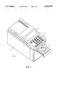
- FIG. 1is an perspective drawing showing the exterior of a photometric fluid analyzer according to the present invention
- FIG. 2is a plan view of a sample rotor for use with the analyzer
- FIG. 3is a schematic diagram depicting the optical path taken by light through the analyzer
- FIG. 4is an illustration showing the interrelationship of an arc lamp, a sample cuvette, and a pair of apertures within the analyzer;
- FIG. 5is a schematic diagram depicting control of various analyzer system functions by a pair of microprocessors.
- FIG. 6is a schematic diagram depicting the processing of signals from a light detector by elements of one of the microprocessors.
- the present inventionprovides a compact, highly automated photometric analyzer system for determining the concentration of various components present in a fluid sample, which may be a blood sample or other body fluid sample taken from a patient.
- FIG. 1depicts an analyzer according to the present invention.
- analyzer 5comprises an exterior housing 7, an input keyboard 10, a liquid crystal display 13, and a motorized sliding tray 17.
- Sliding tray 17is adapted to receive a special sample rotor. The rotor is described in more detail below.
- FIG. 2is a plan view of a sample rotor suitable for use in an analyzer according to the invention.
- Sample rotor 20is in the form of a circular disk suitable for loading into the sliding tray of the analyzer unit.
- the rotoris made of molded plastic and is approximately 8 cm in diameter by 2 cm thick.
- the configuration of the rotoris not a primary aspect of the present invention. Further details of the rotor construction may be found in U.S. Pat. Nos. 5,061,381; 5,173,193; 5,186,844; 5,122,284; and U.S. patent application Ser. Nos. 07/747,179; 07/783,041; 07/833,689; and 07/862,041, the complete disclosures of which are incorporated herein by reference.
- the rotorcomprises a series of many interlinked internal chambers and passages and that movement of fluid through the rotor is controlled by a series of stop junctions, capillaries, and siphons acting in conjunction with centrifugal force applied by spinning the rotor.
- Sample rotor 20is designed for the analysis of a blood sample taken from a patient.
- the rotorhas a blood application site 23, a blood overflow container 24, a diluent container 26, and a plurality of cuvettes 30, including assay cuvettes 33 and reference cuvettes 35, disposed along the outer edge of the disk.
- the rotoris used as follows. First, a blood sample is taken from a patient. The blood sample may be taken from a vein or from a finger stick. The sample need not be precisely measured; between 40 and 100 microliters of blood is sufficient. The operator of the system applies the sample to blood application site 23. The rotor is then placed into sliding tray 17 (FIG. 1) of the analyzer.
- the trayaccepts the rotor and retracts into the body of the analyzer in a manner similar to the sliding tray on a compact disk player.
- a spindlecoupled to a motor engages the bottom of the sample rotor.
- the spindlecauses diluent container 26 to open, thereby allowing the diluent to mix with a predetermined amount of the blood sample. Excess blood from the sample flows into blood overflow container 24 and is held there inside the rotor.
- the blood samplemixes to homogeneity with the diluent.
- the blood cellsare separated from the diluted plasma by centrifugal force.
- Other rotorscould be designed in which separation of the blood cells occurs before dilution of the plasma.
- the diluted plasmais distributed through the internal channels of the rotor into cuvettes 30.
- cuvettes 33Some of the cuvettes are assay cuvettes 33. These assay cuvettes hold specially formulated reagent beads. The reagent beads dissolve in the plasma and chemical reactions are initiated between components of the diluted plasma and the reagent beads. Other cuvettes serve as reference cuvettes 35. Chemical reactions with the fluid sample do not take place in the reference cuvettes. Instead, the contents of the reference cuvettes are compared with the contents of the assay cuvettes as part of the test procedure.
- the chemical reactions taking place in the assay cuvettesare monitored photometrically. Up to fifty different tests can be performed automatically by the analyzer. Some of the tests are endpoint tests, that is, the result is computed based on the amount of a given reaction product left in the cuvette when the reaction is completed. For endpoint tests, the analyzer makes a series of measurements and compares them with one another until criteria are met that indicate the reaction has gone to completion.
- Rate testswhich depend on the rate of formation of a known reaction product within the cuvette. Each test is performed by the analyzer according to known and accepted analytical procedures. For rate tests, the analyzer compares successive measurements and computes the rate at which the reaction product is being formed.
- One of the cuvettesholds an opaque body 38, which may be in the form of a black ball or disk. Opaque body 38 completely blocks light transmission through the cuvette.
- the opaque bodyserves as a reference cuvette for the elimination of offsets in the system electronics. This compensation procedure is described further below.
- one of the cuvettesis in the form of a through hole 40, a physical opening through the body of the rotor.
- the through holemay serve as a reference cuvette for comparison with one of the assay cuvettes in which a known reaction takes place.
- Through hole 40also makes possible a special "full scale" calibration of the system electronics. Both of these functions are described below.
- the analyzer systemhas a highly compact optical system, which allows for the simultaneous measurements of light absorption at a plurality of wavelengths.
- the optical systemis depicted schematically in FIG. 3. As depicted therein, white light (comprising a continuum of wavelengths) from an arc lamp 45 is reflected by a mirror 47 through one of the cuvettes 30 of rotor 20.
- a high intensity light sourceprovides a high signal to noise ratio.
- the arc lamp used in the present embodimentdischarges approximately 0.1 joules of energy during a flash of approximately 5 microseconds (5 ⁇ 10 -6 seconds) duration. Thus, during the brief time that the arc lamp is illuminated, it discharges energy at a rate of some 20,000 watts. Because the arc lamp flash is so brief, the average power consumption is far less than would be the case with a continuous source of light such as an incandescent lamp. Use of an incandescent lamp operating (and therefore producing heat) at an average power consumption of 20,000 watts would be highly impractical.
- the arc lampalso produces its high intensity light in a very small gap.
- the electric arc found in the present embodimentis only about 1.5 millimeters in width. In an electric arc lamp, the arc width corresponds closely to the distance between the electrodes.
- This very small light sourcefacilitates the compact design of the rest of the optical system and in particular, the use of compact sample cuvettes having diameters and optical path lengths of just a few millimeters.
- Rotors presently in usehave cuvettes with lengths of 1.7, 2.1, 4.3, and 5.0 mm, and diameters of about 4 mm or less.
- light from arc lamp 45is partially absorbed by the contents of cuvette 30.
- the degree to which the light is absorbedis dependant upon the light wavelength and upon the contents of the cuvette, i.e., what chemical constituents are present and in what concentrations.
- the lightAfter exiting the cuvette, the light travels through apertures 50 and 52 and through a collimating lens 54.
- each detector assembly 60comprises a beam splitter 62, an interference filter 64, and a photodetector 66.
- the first three beam splitters 67, 68, and 69are wavelength discriminating.
- First beam splitter 67reflects light having a wavelength less than approximately 360 nanometers and transmits light having a wavelength above that.
- second and third beam splitters 68 and 69reflect light having wavelengths below 395 and 415 nanometers, respectively. It has been found that use of these three wavelength discriminating beam splitters results in sufficient light being transmitted to allow for a series of nine beam splitters and associated detector assemblies as depicted in FIG. 3.
- beam splitters 70are in the form of simple unsilvered glass plates. Each of these glass plates reflects about six percent of all light falling upon it (substantially irrespective of wavelength).
- each beam splitterAssociated with each beam splitter are an interference filter 64 and a photodetector 66.
- the interference filtersfilter out all light except that having a wavelength within a narrow band centered about a preselected value.
- the wavelengths passed by the interference filtersare, from the first detector assembly to the last, as follows: 340, 380, 405, 467, 500, 550, 600, 760 and 850 nanometers. These wavelengths were chosen to correspond to the chemical reactions taking place between the dilute samples and the reagent beads in the rotor.
- each of the photodetectorsdetects substantially monochromatic light having a wavelength preselected to match the clinical chemistries used in the various assay cuvettes of the rotor.
- This system of serial detector assembliesallows for the measurement of light absorption at a number of discrete wavelengths simultaneously within a single cuvette.
- the individual detector assemblies 60are disposed in a "zig-zag" pattern in which the photodetectors are arrayed in an alternating pattern on opposite sides of the light path.
- Thisis advantageous because the light path is offset somewhat as the light is transmitted through the beam splitters.
- This alternating patternmeans that the offset in a given beam splitter is corrected by a corresponding (opposite) offset in the next beam splitter. This correction helps to ensure that every photodetector is exposed to an equivalent view of the lamp and the cuvette.
- One of the wavelengths for which light absorption is measuredis 850 nanometers.
- This particular wavelengthis unaffected, i.e., not absorbed, by the products of the chemical reactions relied upon in the testing procedures. Any light absorbed at 850 nanometers must therefore be due to phenomena other than the analytical reactions taking place in the cuvettes.
- the 850 nanometer lightis affected by these other extraneous phenomena to almost exactly the same degree as light having the selected measurement wavelengths.
- intensity of the light at 850 nanometersis available for use as a convenient reference intensity.
- the reference cuvettemay be the through hole in the rotor, or a cuvette in which the chemical reaction of interest is not taking place because the active reagent is not present.
- the reference cuvettemay be the through hole in the rotor, or a cuvette in which the chemical reaction of interest is not taking place because the active reagent is not present.
- FIG. 3shows a mirror 47 disposed between arc lamp 45 and rotor 20.
- Mirror 47merely changes the direction of the light path between the lamp and the rotor by 90°. For clarity, the mirror has therefore been omitted from FIG. 4.
- apertures 50 and 52are positioned and sized to meet two independent criteria.
- the apertureslimit light entering the region of the detectors to light which has traversed cuvette 30. This is beneficial in that the detectors are allowed to "see” only the cuvette and the effects of extraneous conditions are thereby minimized.
- the positions and sizes of apertures 50 and 52 relative to arc lamp 45are such that light from across the full width of the lamp is allowed to enter the detectors.
- the position of the arc between the electrodesmay vary somewhat between from flash to flash. Both the intensity and the spectral content at a given position between the electrodes may therefore vary significantly from one flash to another.
- the total energy discharged across the arc and the average spectral content of the full arcwill be very nearly constant from flash to flash. Sizing the apertures to allow light from across the full width of the arc to strike the detectors minimizes the effect of variations between individual flashes.
- the dimensions used in the present embodimentare as follows.
- the optical path length between the center of arc lamp 45 and the top 72 of rotor 20is approximately 50 mm. In the analyzer, this path length is equal to the sum of the distance between the center of lamp 45 and mirror 47 (FIG. 3) and the distance between the mirror and the top 72 of rotor 20. The distance between the top 72 and bottom 74 of rotor 20 is about 8 mm.
- the optical path length through cuvette 30varies depending on the clinical chemistry employed. Cuvettes having lengths of 1.7, 2.1, 4.3, and 5.0 mm are used for different analytical reactions.
- First aperture 50is a circular (pinhole) aperture having a diameter of 0.5 mm.
- First aperture 50is positioned about 2 mm from the bottom 74 of rotor 20.
- Second aperture 52is a circular aperture 1.0 mm in diameter.
- Second aperture 52is positioned 15 mm away from first aperture 50.
- collimating lens 54is located with its flat surface 2.5 mm away from second aperture 52.
- Lens 54has a focal length of 15 mm. Once the light has left collimating lens 54 the exact positions of the individual beam splitters are not critical so long as they are positioned further along the light path.
- the above dimensionswere derived empirically and by graphical analysis to satisfy the two criteria mentioned above: 1) the photodetectors are allowed to see only light that has traversed the cuvette; and 2) the photodetectors are exposed to light from the full width of the lamp. Additionally, a ray tracing software program was used as an aid in sizing and positioning collimating lens 54. Lens 54 was designed to minimize the cross sectional area of the illuminating beam so that the size of the detectors could likewise be minimized consistent with each detector being exposed to light from the full width of the lamp. These considerations contribute to the exceedingly compact construction of the entire system. Notably, the distance between first aperture 50 and the last of the nine beam splitters is only about 65 mm.
- first and second microprocessors 75 and 78are Intel 80C196 microprocessors.
- First microprocessor 75controls the measurement functions while second microprocessor 78 specializes in user-interface functions.
- First microprocessor 75controls the speed and acceleration of motor 80, which is coupled to a spindle 81 for engagement with rotor 20; monitors a cuvette position detector 83; controls the measurement electronics; and processes data from the photodetectors 66.
- First microprocessor 75also interfaces with a bar code reader 86, which reads a bar code printed around the perimeter of the rotor. The bar code identifies the type of rotor and carries calibration information specific to the chemical lots of the reagents used in that rotor.
- First microprocessor 75controls the flashing of arc lamp 45 based on information from cuvette position detector 83.
- the sample rotorhas a pattern of mirrored elements around its rim whose positions are monitored with great precision by cuvette position detector 83.
- the microprocessorensures that the lamp is flashed at a time when one of the cuvettes is properly aligned with the apertures.
- the timing of the flashesis therefore dependant upon the speed of the rotor.
- the rotorspins during measurement at approximately 1200 rpm and the lamp flashes through one cuvette per rotor revolution.
- the time between lamp flashesis therefore about 50 milliseconds.
- single cuvettetraverses the apertures in about 100 microseconds.
- Second microprocessor 78completes the calculation of analytical results from data that were transferred from the first microprocessor. Additionally, the second microprocessor controls keyboard 10, through which the user can input information such as an operator number or a patient identification number. This microprocessor also controls liquid crystal display 13 and a printer 89. The printer prints the test results for convenient reference by a physician or other caregiver. Finally, second microprocessor 78 is connected to an RS-232 computer interface 93, through which the analyzer may be connected to a host computer for the convenient uploading of information for record keeping and billing, as well as for tracking quality-control parameters. Information may also be input to the analyzer from a computer through interface 93. The entire system is powered by standard household power through a power supply 95. Alternatively, portable analyzer systems can utilize battery power.
- each of the nine photodetectors 66comprises a sensing element 100 and a front end amplifier 102.
- Light energy impinging on sensing element 100is converted into an amplified electrical signal by front end amplifier 102 before being sent to first microprocessor 75.
- the first microprocessorwhose function is described above, includes circuitry that functions as a multiplexer 105, a variable gain amplifier 108, an analog-to-digital converter 112, and storage, computation, and control means 115.
- Multiplexer 105 of microprocessor 75selectively couples the microprocessor to the detectors so that signals are received from one selected detector at a time.
- Multiplexer 105includes sample and hold means in which a signal level is temporarily stored for later processing. From the multiplexer, the signal is sent to a variable gain amplifier 108, which allows for calibration of the signal as is described further below. The analog signal level is then converted to a digital value in analog-to-digital converter 112 before being sent to storage, computation, and control circuitry 115.
- Calibration levelsare calculated by microprocessor 75 so that variable gain amplifier 108 can be adjusted to provide a near optimum full scale signal to analog-to-digital converter 112.
- sample rotor 20has a through hole 40 near its outer edge in the place of one of the cuvettes. Prior to the computation of chemical concentrations, light is flashed through the through hole 40 onto the detectors. For each detector, variable gain amplifier 108 is adjusted until the signal output from that detector 66 to analog-to-digital converter 112 is near the maximum input level of the converter. In the current embodiment, variable gain amplifier 108 is adjusted to output a signal equal to ninety percent of the converter's maximum input level.
- the computed full-scale gain level for the variable gain amplifieris determined and stored in first microprocessor 75 separately for each detector. When measurements are being taken later, the stored gain levels are applied to the detector signals by variable gain amplifier 108 under the control of first microprocessor 75. This calibration procedure allows the detectors to take advantage of nearly the full range of the analog-to-digital converter without exceeding its range.
- the calibration procedurealso compensates automatically for the decreasing brightness of the lamp as it ages. As the light from the lamp grows progressively more dim, the optimal gain levels calculated and stored for each detector will increase to a corresponding degree. This insures that nearly the full range of the analog-to-digital converter will be utilized throughout the life of the lamp.
- Aging of the lampis monitored automatically by the system. Each time a new rotor is loaded, a value corresponding to the measured intensity of the lamp through the through hole is compared to a value stored in the microprocessor. The stored value corresponds to the intensity of the lamp when new. When the measured intensity drops to a preselected fraction, typically about 50 percent, of the original intensity, an indicator signal is sent to the LCD display to indicate to the operator of the system that the lamp should be changed.
- a preselected fractiontypically about 50 percent
- a related procedureis provided for detecting errors which might occur due to contamination of the optical system or other problems in the analyzer.
- Historical informationtypically a running average, corresponding to the lamp intensity as measured through the through hole is stored and maintained in the microprocessor. Should any one measurement diverge too widely from the running average, an error indication is displayed. In case of contamination of the optics, problems with the power supply, or other problems with the system, the indicated intensity of the lamp would suddenly decrease. This sudden divergence from the running average would trigger the error indication.
- sample rotor 20has an opaque body 38 in the place of one of the cuvettes.
- this opaque bodyis a solid object in the present embodiment, it could be in the form of a cuvette filled with a liquid dyed sufficiently dark to be effectively opaque.
- the lampis flashed and the detectors read while opaque body 38 is aligned with the apertures to prevent light from the lamp from impinging on the detectors. Any signals in the detectors will therefore be erroneous, due either to false current offsets within the system electronics or to stray light striking the detectors. For each detector, a corresponding "dark current" value is stored in the microprocessor for later subtraction from the values measured by the detectors during the measurement process.
- multiple measurementsare taken through a single cuvette and averaged to eliminate errors due to random noise.
- a given cuvettepasses the apertures once during each revolution of the rotor.
- the arc lampis flashed, and measurements are taken and stored for later calculations.
- the number of flashes usedvaries depending on the clinical chemistry. In the present embodiment, between 10 and 200 flashes are typically averaged for a given cuvette.
- the present inventionprovides a compact, convenient, and highly automated system for the photometric analysis of fluids, typically blood or other body fluid samples from a patient.
- the systemis capable of measuring light absorption values at a number of wavelengths.
- the analyzeralso includes several advanced calibration and error compensation systems. As a result, the system is capable of rapidly performing a large number of chemical tests to a high degree of precision.
- the analyzeris compact and inexpensive enough to allow its widespread use in hospitals, clinics, and doctors' offices. With battery power, even portable systems can be provided.
Landscapes
- Physics & Mathematics (AREA)
- Biochemistry (AREA)
- Health & Medical Sciences (AREA)
- Life Sciences & Earth Sciences (AREA)
- Chemical & Material Sciences (AREA)
- Analytical Chemistry (AREA)
- General Health & Medical Sciences (AREA)
- General Physics & Mathematics (AREA)
- Immunology (AREA)
- Pathology (AREA)
- Spectroscopy & Molecular Physics (AREA)
- Optical Measuring Cells (AREA)
- Investigating Or Analysing Materials By Optical Means (AREA)
Abstract
Description
Claims (3)
Priority Applications (1)
| Application Number | Priority Date | Filing Date | Title |
|---|---|---|---|
| US08/292,558US5478750A (en) | 1993-03-31 | 1994-08-18 | Methods for photometric analysis |
Applications Claiming Priority (2)
| Application Number | Priority Date | Filing Date | Title |
|---|---|---|---|
| US4054993A | 1993-03-31 | 1993-03-31 | |
| US08/292,558US5478750A (en) | 1993-03-31 | 1994-08-18 | Methods for photometric analysis |
Related Parent Applications (1)
| Application Number | Title | Priority Date | Filing Date |
|---|---|---|---|
| US4054993AContinuation | 1993-03-31 | 1993-03-31 |
Publications (1)
| Publication Number | Publication Date |
|---|---|
| US5478750Atrue US5478750A (en) | 1995-12-26 |
Family
ID=21911600
Family Applications (1)
| Application Number | Title | Priority Date | Filing Date |
|---|---|---|---|
| US08/292,558Expired - LifetimeUS5478750A (en) | 1993-03-31 | 1994-08-18 | Methods for photometric analysis |
Country Status (1)
| Country | Link |
|---|---|
| US (1) | US5478750A (en) |
Cited By (83)
| Publication number | Priority date | Publication date | Assignee | Title |
|---|---|---|---|---|
| US5627041A (en)* | 1994-09-02 | 1997-05-06 | Biometric Imaging, Inc. | Disposable cartridge for an assay of a biological sample |
| EP0807811A3 (en)* | 1996-05-17 | 1998-03-18 | Pfizer Inc. | Spectrophotometric analysis |
| US5916522A (en)* | 1997-08-07 | 1999-06-29 | Careside, Inc. | Electrochemical analytical cartridge |
| US5919711A (en)* | 1997-08-07 | 1999-07-06 | Careside, Inc. | Analytical cartridge |
| US6002475A (en)* | 1998-01-28 | 1999-12-14 | Careside, Inc. | Spectrophotometric analytical cartridge |
| WO2000047977A1 (en)* | 1999-02-11 | 2000-08-17 | Careside, Inc. | Cartridge-based analytical instrument |
| US6143247A (en)* | 1996-12-20 | 2000-11-07 | Gamera Bioscience Inc. | Affinity binding-based system for detecting particulates in a fluid |
| US6143248A (en)* | 1996-08-12 | 2000-11-07 | Gamera Bioscience Corp. | Capillary microvalve |
| US6300142B1 (en)* | 1997-11-28 | 2001-10-09 | Provalis Diagnostics Ltd | Device and apparatus for conducting an assay |
| US6302134B1 (en) | 1997-05-23 | 2001-10-16 | Tecan Boston | Device and method for using centripetal acceleration to device fluid movement on a microfluidics system |
| US6348176B1 (en) | 1999-02-11 | 2002-02-19 | Careside, Inc. | Cartridge-based analytical instrument using centrifugal force/pressure for metering/transport of fluids |
| US6391264B2 (en) | 1999-02-11 | 2002-05-21 | Careside, Inc. | Cartridge-based analytical instrument with rotor balance and cartridge lock/eject system |
| US20020071359A1 (en)* | 2000-12-08 | 2002-06-13 | Worthington Mark Oscar | Methods for detecting analytes using optical discs and optical disc readers |
| US20020097632A1 (en)* | 2000-05-15 | 2002-07-25 | Kellogg Gregory J. | Bidirectional flow centrifugal microfluidic devices |
| US20020118355A1 (en)* | 2000-11-08 | 2002-08-29 | Worthington Mark Oscar | Interactive system for analyzing biological samples and processing related information and the use thereof |
| US20020171838A1 (en)* | 2001-05-16 | 2002-11-21 | Pal Andrew Attila | Variable sampling control for rendering pixelization of analysis results in a bio-disc assembly and apparatus relating thereto |
| US20020176068A1 (en)* | 2000-01-18 | 2002-11-28 | Henrik Fodgaard | Apparatus, sample cuvette and method for optical measurements |
| US6511814B1 (en) | 1999-03-26 | 2003-01-28 | Idexx Laboratories, Inc. | Method and device for detecting analytes in fluids |
| US6531095B2 (en) | 1999-02-11 | 2003-03-11 | Careside, Inc. | Cartridge-based analytical instrument with optical detector |
| US6551842B1 (en) | 1999-03-26 | 2003-04-22 | Idexx Laboratories, Inc. | Method and device for detecting analytes in fluids |
| US20030096324A1 (en)* | 2001-09-12 | 2003-05-22 | Mikhail Matveev | Methods for differential cell counts including related apparatus and software for performing same |
| US20030129665A1 (en)* | 2001-08-30 | 2003-07-10 | Selvan Gowri Pyapali | Methods for qualitative and quantitative analysis of cells and related optical bio-disc systems |
| US6602719B1 (en) | 1999-03-26 | 2003-08-05 | Idexx Laboratories, Inc. | Method and device for detecting analytes in fluids |
| US6632399B1 (en) | 1998-05-22 | 2003-10-14 | Tecan Trading Ag | Devices and methods for using centripetal acceleration to drive fluid movement in a microfluidics system for performing biological fluid assays |
| US20030219713A1 (en)* | 2001-11-20 | 2003-11-27 | Valencia Ramoncito Magpantay | Optical bio-discs and fluidic circuits for analysis of cells and methods relating thereto |
| US20030232403A1 (en)* | 1999-06-18 | 2003-12-18 | Kellogg Gregory L. | Devices and methods for the performance of miniaturized homogeneous assays |
| US20040038422A1 (en)* | 2000-09-06 | 2004-02-26 | Percival David Alan | Description |
| US20040038647A1 (en)* | 1993-12-20 | 2004-02-26 | Intermec Technologies Corporation | Local area network having multiple channel wireless access |
| US6709869B2 (en) | 1995-12-18 | 2004-03-23 | Tecan Trading Ag | Devices and methods for using centripetal acceleration to drive fluid movement in a microfluidics system |
| US6723287B1 (en)* | 1999-03-10 | 2004-04-20 | Jeol Ltd. | Measuring system for automatic chemical analyzer |
| US20040166593A1 (en)* | 2001-06-22 | 2004-08-26 | Nolte David D. | Adaptive interferometric multi-analyte high-speed biosensor |
| US20040226348A1 (en)* | 2001-07-24 | 2004-11-18 | Phillip Bruce | Magnetic assisted detection of magnetic beads using optical disc drives |
| US20050014249A1 (en)* | 2003-02-21 | 2005-01-20 | Norbert Staimer | Chromatographic analysis on optical bio-discs and methods relating thereto |
| US20050018583A1 (en)* | 2000-12-08 | 2005-01-27 | Worthington Mark O. | Multiple data layer optical discs for detecting analytes |
| US20050037505A1 (en)* | 2000-05-11 | 2005-02-17 | James Samsoondar | Spectroscopic method and apparatus for analyte measurement |
| US20050053260A1 (en)* | 1999-08-23 | 2005-03-10 | Worthington Mark O. | Methods and apparatus for analyzing operational and analyte data acquired from optical discs |
| US20050283318A1 (en)* | 2002-10-18 | 2005-12-22 | Abaxis, Inc. | Systems for the detection of short and long samples |
| US7097981B1 (en)* | 1998-09-11 | 2006-08-29 | Biomerieux | Reaction wells, assembly thereof, immunoassay apparatus and method using such well assemblies |
| US20060263265A1 (en)* | 2005-05-23 | 2006-11-23 | Der-Ren Kang | Blood micro-separator |
| US20070023643A1 (en)* | 2005-02-01 | 2007-02-01 | Nolte David D | Differentially encoded biological analyzer planar array apparatus and methods |
| EP1752759A1 (en) | 2005-08-09 | 2007-02-14 | Roche Diagnostics GmbH | Photometric in plane detection using a rotatable disc |
| EP1770398A1 (en) | 2005-10-03 | 2007-04-04 | Francois Melet | Compact dry biochemical analyzer for the analysis of blood samples |
| US20070212257A1 (en)* | 2006-02-16 | 2007-09-13 | Purdue Research Foundation | In-line quadrature and anti-reflection enhanced phase quadrature interferometric detection |
| EP1862792A2 (en) | 2006-05-31 | 2007-12-05 | Ushiodenki Kabushiki Kaisha | Biochemical analysis device |
| US20080002178A1 (en)* | 2006-06-30 | 2008-01-03 | Ushiodenki Kabushiki Kaisha | Microchip testing device |
| US20080171397A1 (en)* | 2007-01-16 | 2008-07-17 | Ian Hardcastle | Multiple analyte detection systems and methods of detecting multiple analytes |
| US20080297769A1 (en)* | 2007-06-01 | 2008-12-04 | Eberhard Bamberg | Through-container optical evaluation system |
| US7522282B2 (en) | 2006-11-30 | 2009-04-21 | Purdue Research Foundation | Molecular interferometric imaging process and apparatus |
| US7659968B2 (en) | 2007-01-19 | 2010-02-09 | Purdue Research Foundation | System with extended range of molecular sensing through integrated multi-modal data acquisition |
| US7663092B2 (en) | 2005-02-01 | 2010-02-16 | Purdue Research Foundation | Method and apparatus for phase contrast quadrature interferometric detection of an immunoassay |
| US7787126B2 (en) | 2007-03-26 | 2010-08-31 | Purdue Research Foundation | Method and apparatus for conjugate quadrature interferometric detection of an immunoassay |
| EP2237020A1 (en)* | 2009-03-31 | 2010-10-06 | François Melet | Device for analysing a blood sample |
| CN101943697A (en)* | 2010-09-01 | 2011-01-12 | 杨军 | Blood examination method, system and microchip |
| US7910356B2 (en) | 2005-02-01 | 2011-03-22 | Purdue Research Foundation | Multiplexed biological analyzer planar array apparatus and methods |
| US20110195502A1 (en)* | 2010-02-05 | 2011-08-11 | Medi Medical Engineering Corp. | Centrifugal rotor and method for using the same for delivering biological sample |
| US20110235042A1 (en)* | 2008-09-30 | 2011-09-29 | Senseair Ab | Arrangement adapted for spectral analysis of high concentrations of gas |
| CN103512847A (en)* | 2013-09-29 | 2014-01-15 | 成都斯马特科技有限公司 | Constant light source detecting method for integrated biochemical reagent disk and detecting device for implementing same |
| US8703070B1 (en) | 2012-04-24 | 2014-04-22 | Industrial Technology Research Institute | Apparatus for immunoassay |
| WO2015051092A1 (en)* | 2013-10-03 | 2015-04-09 | Rosemount Analytical Inc. | Multiple wavelength light source for colorimetric measurement |
| CN104755937A (en)* | 2012-11-14 | 2015-07-01 | 株式会社日立高新技术 | Automated analyzer |
| US9116129B2 (en) | 2007-05-08 | 2015-08-25 | Idexx Laboratories, Inc. | Chemical analyzer |
| WO2017153425A1 (en)* | 2016-03-10 | 2017-09-14 | Archimej Technology | Analysing device, preferably for chemometric measurement of a blood sample |
| US9797916B2 (en) | 2014-01-10 | 2017-10-24 | Idexx Laboratories, Inc. | Chemical analyzer |
| US10022720B2 (en) | 2015-06-12 | 2018-07-17 | Cytochip Inc. | Fluidic units and cartridges for multi-analyte analysis |
| US10077999B2 (en) | 2015-07-14 | 2018-09-18 | Cytochip Inc. | Volume sensing in fluidic cartridge |
| US10533994B2 (en) | 2006-03-24 | 2020-01-14 | Theranos Ip Company, Llc | Systems and methods of sample processing and fluid control in a fluidic system |
| US10557786B2 (en) | 2011-01-21 | 2020-02-11 | Theranos Ip Company, Llc | Systems and methods for sample use maximization |
| US10634667B2 (en) | 2007-10-02 | 2020-04-28 | Theranos Ip Company, Llc | Modular point-of-care devices, systems, and uses thereof |
| US10634602B2 (en) | 2015-06-12 | 2020-04-28 | Cytochip Inc. | Fluidic cartridge for cytometry and additional analysis |
| US10761030B2 (en) | 2005-05-09 | 2020-09-01 | Labrador Diagnostics Llc | System and methods for analyte detection |
| CN111751299A (en)* | 2019-03-29 | 2020-10-09 | 古野电气株式会社 | Analysis device |
| US11094050B2 (en) | 2018-08-24 | 2021-08-17 | Zoetis Services Llc | Systems and methods for inspecting a microfluidic rotor device |
| US11139084B2 (en) | 2009-10-19 | 2021-10-05 | Labrador Diagnostics Llc | Integrated health data capture and analysis system |
| US11162947B2 (en) | 2006-05-10 | 2021-11-02 | Labrador Diagnostics Llc | Real-time detection of influenza virus |
| US11215610B2 (en) | 2006-10-13 | 2022-01-04 | Labrador Diagnostics Llc | Reducing optical interference in a fluidic device |
| US11287421B2 (en) | 2006-03-24 | 2022-03-29 | Labrador Diagnostics Llc | Systems and methods of sample processing and fluid control in a fluidic system |
| US11370177B2 (en) | 2018-08-24 | 2022-06-28 | Zoetis Services Llc | Systems and methods for manufacturing a microfluidic rotor device |
| US11369958B2 (en) | 2018-08-24 | 2022-06-28 | Zoetis Services Llc | Microfluidic rotor device |
| US11491487B2 (en) | 2017-10-23 | 2022-11-08 | Cytochip Inc. | Devices and methods for measuring analytes and target particles |
| US11628452B2 (en) | 2018-08-24 | 2023-04-18 | Zoetis Services Llc | Microfluidic rotor device |
| US11754554B2 (en) | 2007-08-06 | 2023-09-12 | Labrador Diagnostics Llc | Systems and methods of fluidic sample processing |
| US11977091B2 (en) | 2020-07-10 | 2024-05-07 | Idexx Laboratories Inc. | Point-of-care medical diagnostic analyzer and devices, systems, and methods for medical diagnostic analysis of samples |
| US12290810B2 (en) | 2018-08-24 | 2025-05-06 | Zoetis Services Llc | Microfluidic rotor device |
Citations (29)
| Publication number | Priority date | Publication date | Assignee | Title |
|---|---|---|---|---|
| US3833864A (en)* | 1972-11-30 | 1974-09-03 | R Kiess | Digital direct reading colorimeter |
| US3941487A (en)* | 1973-04-16 | 1976-03-02 | Beckman Instruments, Inc. | Colorimetric fluid analyzer |
| US4059357A (en)* | 1976-04-02 | 1977-11-22 | Beckman Instruments, Inc. | Densitometer calibrated reference standard |
| US4176958A (en)* | 1978-02-24 | 1979-12-04 | Beckman Instruments, Inc. | Automatic loop gain adjustment for optical null spectrophotometers |
| US4195932A (en)* | 1978-07-03 | 1980-04-01 | Abbott Laboratories | Absorption spectrophotometer |
| USRE31149E (en)* | 1977-06-20 | 1983-02-15 | Coulter Electronics, Inc. | Apparatus for monitoring chemical reactions and employing moving photometer means |
| US4437762A (en)* | 1981-12-28 | 1984-03-20 | Beckman Instruments, Inc. | Control of detector gain hysteresis in a single beam spectrophotometer |
| US4437763A (en)* | 1981-12-28 | 1984-03-20 | Beckman Instruments, Inc. | Control of detector gain hysteresis in a single beam spectrophotometer |
| US4446871A (en)* | 1980-01-25 | 1984-05-08 | Minolta Kabushiki Kaisha | Optical analyzer for measuring a construction ratio between components in the living tissue |
| GB2150704A (en)* | 1981-04-02 | 1985-07-03 | Abbott Lab | Filter assembly for fluorescence spectroscopy |
| US4536369A (en)* | 1980-03-21 | 1985-08-20 | Olympus Optical Company Limited | Automatic analyzing apparatus |
| EP0167750A2 (en)* | 1984-06-13 | 1986-01-15 | Abbott Laboratories | Spectrophotometer |
| US4566110A (en)* | 1982-09-17 | 1986-01-21 | Coulter Electronics, Inc. | Auto-zeroing linear analog to digital converter apparatus and method |
| US4629703A (en)* | 1981-08-27 | 1986-12-16 | Technicon Instruments Corporation | Automated analytical system |
| US4687329A (en)* | 1985-03-21 | 1987-08-18 | Abbott Laboratories | Spectrophotometer |
| US4694833A (en)* | 1982-02-19 | 1987-09-22 | Minolta Camera Kabushiki Kaisha | Noninvasive device for photoelectrically measuring the property of arterial blood |
| US4744657A (en)* | 1985-07-11 | 1988-05-17 | Beckman Instruments, Inc. | Method and record for calibration of a spectrophotometer |
| US4773422A (en)* | 1987-04-30 | 1988-09-27 | Nonin Medical, Inc. | Single channel pulse oximeter |
| US4785407A (en)* | 1985-11-19 | 1988-11-15 | Olympus Optical Co., Ltd. | Automatic chemical analyzer with selective removal of reaction vessels |
| US4826319A (en)* | 1984-09-07 | 1989-05-02 | Olympus Optical Co., Ltd. | Method and apparatus for measuring immunological reaction with the aid of fluctuation in intensity of scattered light |
| US5061381A (en)* | 1990-06-04 | 1991-10-29 | Abaxis, Inc. | Apparatus and method for separating cells from biological fluids |
| US5122284A (en)* | 1990-06-04 | 1992-06-16 | Abaxis, Inc. | Apparatus and method for optically analyzing biological fluids |
| US5183638A (en)* | 1989-12-04 | 1993-02-02 | Kabushiki Kaisha Nittec | Automatic immunity analysis apparatus with magnetic particle separation |
| US5204264A (en)* | 1991-03-14 | 1993-04-20 | E. I. Du Pont De Nemours And Company | Method for validation of calibration standards in an automatic chemical analyzer |
| US5212094A (en)* | 1986-09-16 | 1993-05-18 | Kabushiki Kaisha Toshiba | Automatic chemical analyzer |
| US5219526A (en)* | 1990-04-27 | 1993-06-15 | Pb Diagnostic Systems Inc. | Assay cartridge |
| US5230863A (en)* | 1987-07-21 | 1993-07-27 | Si Industrial Instruments, Inc. | Method of calibrating an automatic chemical analyzer |
| US5234835A (en)* | 1991-09-26 | 1993-08-10 | C.R. Bard, Inc. | Precalibrated fiber optic sensing method |
| US5242803A (en)* | 1987-07-17 | 1993-09-07 | Martin Marietta Energy Systems, Inc. | Rotor assembly and assay method |
- 1994
- 1994-08-18USUS08/292,558patent/US5478750A/ennot_activeExpired - Lifetime
Patent Citations (29)
| Publication number | Priority date | Publication date | Assignee | Title |
|---|---|---|---|---|
| US3833864A (en)* | 1972-11-30 | 1974-09-03 | R Kiess | Digital direct reading colorimeter |
| US3941487A (en)* | 1973-04-16 | 1976-03-02 | Beckman Instruments, Inc. | Colorimetric fluid analyzer |
| US4059357A (en)* | 1976-04-02 | 1977-11-22 | Beckman Instruments, Inc. | Densitometer calibrated reference standard |
| USRE31149E (en)* | 1977-06-20 | 1983-02-15 | Coulter Electronics, Inc. | Apparatus for monitoring chemical reactions and employing moving photometer means |
| US4176958A (en)* | 1978-02-24 | 1979-12-04 | Beckman Instruments, Inc. | Automatic loop gain adjustment for optical null spectrophotometers |
| US4195932A (en)* | 1978-07-03 | 1980-04-01 | Abbott Laboratories | Absorption spectrophotometer |
| US4446871A (en)* | 1980-01-25 | 1984-05-08 | Minolta Kabushiki Kaisha | Optical analyzer for measuring a construction ratio between components in the living tissue |
| US4536369A (en)* | 1980-03-21 | 1985-08-20 | Olympus Optical Company Limited | Automatic analyzing apparatus |
| GB2150704A (en)* | 1981-04-02 | 1985-07-03 | Abbott Lab | Filter assembly for fluorescence spectroscopy |
| US4629703A (en)* | 1981-08-27 | 1986-12-16 | Technicon Instruments Corporation | Automated analytical system |
| US4437763A (en)* | 1981-12-28 | 1984-03-20 | Beckman Instruments, Inc. | Control of detector gain hysteresis in a single beam spectrophotometer |
| US4437762A (en)* | 1981-12-28 | 1984-03-20 | Beckman Instruments, Inc. | Control of detector gain hysteresis in a single beam spectrophotometer |
| US4694833A (en)* | 1982-02-19 | 1987-09-22 | Minolta Camera Kabushiki Kaisha | Noninvasive device for photoelectrically measuring the property of arterial blood |
| US4566110A (en)* | 1982-09-17 | 1986-01-21 | Coulter Electronics, Inc. | Auto-zeroing linear analog to digital converter apparatus and method |
| EP0167750A2 (en)* | 1984-06-13 | 1986-01-15 | Abbott Laboratories | Spectrophotometer |
| US4826319A (en)* | 1984-09-07 | 1989-05-02 | Olympus Optical Co., Ltd. | Method and apparatus for measuring immunological reaction with the aid of fluctuation in intensity of scattered light |
| US4687329A (en)* | 1985-03-21 | 1987-08-18 | Abbott Laboratories | Spectrophotometer |
| US4744657A (en)* | 1985-07-11 | 1988-05-17 | Beckman Instruments, Inc. | Method and record for calibration of a spectrophotometer |
| US4785407A (en)* | 1985-11-19 | 1988-11-15 | Olympus Optical Co., Ltd. | Automatic chemical analyzer with selective removal of reaction vessels |
| US5212094A (en)* | 1986-09-16 | 1993-05-18 | Kabushiki Kaisha Toshiba | Automatic chemical analyzer |
| US4773422A (en)* | 1987-04-30 | 1988-09-27 | Nonin Medical, Inc. | Single channel pulse oximeter |
| US5242803A (en)* | 1987-07-17 | 1993-09-07 | Martin Marietta Energy Systems, Inc. | Rotor assembly and assay method |
| US5230863A (en)* | 1987-07-21 | 1993-07-27 | Si Industrial Instruments, Inc. | Method of calibrating an automatic chemical analyzer |
| US5183638A (en)* | 1989-12-04 | 1993-02-02 | Kabushiki Kaisha Nittec | Automatic immunity analysis apparatus with magnetic particle separation |
| US5219526A (en)* | 1990-04-27 | 1993-06-15 | Pb Diagnostic Systems Inc. | Assay cartridge |
| US5061381A (en)* | 1990-06-04 | 1991-10-29 | Abaxis, Inc. | Apparatus and method for separating cells from biological fluids |
| US5122284A (en)* | 1990-06-04 | 1992-06-16 | Abaxis, Inc. | Apparatus and method for optically analyzing biological fluids |
| US5204264A (en)* | 1991-03-14 | 1993-04-20 | E. I. Du Pont De Nemours And Company | Method for validation of calibration standards in an automatic chemical analyzer |
| US5234835A (en)* | 1991-09-26 | 1993-08-10 | C.R. Bard, Inc. | Precalibrated fiber optic sensing method |
Cited By (145)
| Publication number | Priority date | Publication date | Assignee | Title |
|---|---|---|---|---|
| US20040038647A1 (en)* | 1993-12-20 | 2004-02-26 | Intermec Technologies Corporation | Local area network having multiple channel wireless access |
| US5627041A (en)* | 1994-09-02 | 1997-05-06 | Biometric Imaging, Inc. | Disposable cartridge for an assay of a biological sample |
| US6319468B1 (en) | 1995-06-27 | 2001-11-20 | Tecan Trading Ag | Affinity binding-based system for detecting particulates in a fluid |
| US6709869B2 (en) | 1995-12-18 | 2004-03-23 | Tecan Trading Ag | Devices and methods for using centripetal acceleration to drive fluid movement in a microfluidics system |
| EP0807811A3 (en)* | 1996-05-17 | 1998-03-18 | Pfizer Inc. | Spectrophotometric analysis |
| US5859703A (en)* | 1996-05-17 | 1999-01-12 | Pfizer Inc. | Spectrophotometric analysis |
| US6143248A (en)* | 1996-08-12 | 2000-11-07 | Gamera Bioscience Corp. | Capillary microvalve |
| US6656430B2 (en) | 1996-12-20 | 2003-12-02 | Tecan Trading Ag | Affinity binding-based system for detecting particulates in a fluid |
| US6143247A (en)* | 1996-12-20 | 2000-11-07 | Gamera Bioscience Inc. | Affinity binding-based system for detecting particulates in a fluid |
| US6548788B2 (en) | 1997-05-23 | 2003-04-15 | Tecan Trading Ag | Devices and methods for using centripetal acceleration to drive fluid movement in a microfluidics system |
| US6399361B2 (en) | 1997-05-23 | 2002-06-04 | Tecan Trading Ag | Devices and methods for using centripetal acceleration to drive fluid movement in a microfluidics system |
| US6302134B1 (en) | 1997-05-23 | 2001-10-16 | Tecan Boston | Device and method for using centripetal acceleration to device fluid movement on a microfluidics system |
| US20040089616A1 (en)* | 1997-05-23 | 2004-05-13 | Gregory Kellogg | Devices and methods for using centripetal acceleration to drive fluid movement in a microfluidics system for performing biological fluid assays |
| US5916522A (en)* | 1997-08-07 | 1999-06-29 | Careside, Inc. | Electrochemical analytical cartridge |
| US5919711A (en)* | 1997-08-07 | 1999-07-06 | Careside, Inc. | Analytical cartridge |
| US6033914A (en)* | 1997-08-07 | 2000-03-07 | Careside, Inc. | Electrochemical analytical cartridge |
| US6300142B1 (en)* | 1997-11-28 | 2001-10-09 | Provalis Diagnostics Ltd | Device and apparatus for conducting an assay |
| US6002475A (en)* | 1998-01-28 | 1999-12-14 | Careside, Inc. | Spectrophotometric analytical cartridge |
| US6632399B1 (en) | 1998-05-22 | 2003-10-14 | Tecan Trading Ag | Devices and methods for using centripetal acceleration to drive fluid movement in a microfluidics system for performing biological fluid assays |
| US7097981B1 (en)* | 1998-09-11 | 2006-08-29 | Biomerieux | Reaction wells, assembly thereof, immunoassay apparatus and method using such well assemblies |
| US6391264B2 (en) | 1999-02-11 | 2002-05-21 | Careside, Inc. | Cartridge-based analytical instrument with rotor balance and cartridge lock/eject system |
| US6348176B1 (en) | 1999-02-11 | 2002-02-19 | Careside, Inc. | Cartridge-based analytical instrument using centrifugal force/pressure for metering/transport of fluids |
| WO2000047977A1 (en)* | 1999-02-11 | 2000-08-17 | Careside, Inc. | Cartridge-based analytical instrument |
| US6531095B2 (en) | 1999-02-11 | 2003-03-11 | Careside, Inc. | Cartridge-based analytical instrument with optical detector |
| US6723287B1 (en)* | 1999-03-10 | 2004-04-20 | Jeol Ltd. | Measuring system for automatic chemical analyzer |
| US6602719B1 (en) | 1999-03-26 | 2003-08-05 | Idexx Laboratories, Inc. | Method and device for detecting analytes in fluids |
| US6551842B1 (en) | 1999-03-26 | 2003-04-22 | Idexx Laboratories, Inc. | Method and device for detecting analytes in fluids |
| US6511814B1 (en) | 1999-03-26 | 2003-01-28 | Idexx Laboratories, Inc. | Method and device for detecting analytes in fluids |
| US20030232403A1 (en)* | 1999-06-18 | 2003-12-18 | Kellogg Gregory L. | Devices and methods for the performance of miniaturized homogeneous assays |
| US7664289B2 (en) | 1999-08-23 | 2010-02-16 | Vindur Technologies, Inc. | Methods and apparatus for analyzing operational and analyte data acquired from optical discs |
| US20050053260A1 (en)* | 1999-08-23 | 2005-03-10 | Worthington Mark O. | Methods and apparatus for analyzing operational and analyte data acquired from optical discs |
| US6888951B1 (en) | 1999-08-23 | 2005-05-03 | Nagaoka & Co., Ltd. | Methods and apparatus for analyzing operational and analyte data acquired from optical disc |
| US20020176068A1 (en)* | 2000-01-18 | 2002-11-28 | Henrik Fodgaard | Apparatus, sample cuvette and method for optical measurements |
| US6943883B2 (en) | 2000-01-18 | 2005-09-13 | Radiometer Medical A/S | Apparatus, sample cuvette and method for optical measurements |
| US20050037505A1 (en)* | 2000-05-11 | 2005-02-17 | James Samsoondar | Spectroscopic method and apparatus for analyte measurement |
| US6527432B2 (en)* | 2000-05-15 | 2003-03-04 | Tecan Trading Ag | Bidirectional flow centrifugal microfluidic devices |
| US20020097632A1 (en)* | 2000-05-15 | 2002-07-25 | Kellogg Gregory J. | Bidirectional flow centrifugal microfluidic devices |
| US20040038422A1 (en)* | 2000-09-06 | 2004-02-26 | Percival David Alan | Description |
| US7481977B2 (en) | 2000-09-06 | 2009-01-27 | Bio-Rad Laboratories, Inc. | Assay device |
| US20020118355A1 (en)* | 2000-11-08 | 2002-08-29 | Worthington Mark Oscar | Interactive system for analyzing biological samples and processing related information and the use thereof |
| US6937323B2 (en) | 2000-11-08 | 2005-08-30 | Burstein Technologies, Inc. | Interactive system for analyzing biological samples and processing related information and the use thereof |
| US7110345B2 (en) | 2000-12-08 | 2006-09-19 | Burstein Technologies, Inc. | Multiple data layer optical discs for detecting analytes |
| US6995845B2 (en) | 2000-12-08 | 2006-02-07 | Burstein Technologies, Inc. | Methods for detecting analytes using optical discs and optical disc readers |
| US20050018583A1 (en)* | 2000-12-08 | 2005-01-27 | Worthington Mark O. | Multiple data layer optical discs for detecting analytes |
| US20020071359A1 (en)* | 2000-12-08 | 2002-06-13 | Worthington Mark Oscar | Methods for detecting analytes using optical discs and optical disc readers |
| US20020171838A1 (en)* | 2001-05-16 | 2002-11-21 | Pal Andrew Attila | Variable sampling control for rendering pixelization of analysis results in a bio-disc assembly and apparatus relating thereto |
| US20040166593A1 (en)* | 2001-06-22 | 2004-08-26 | Nolte David D. | Adaptive interferometric multi-analyte high-speed biosensor |
| US20040226348A1 (en)* | 2001-07-24 | 2004-11-18 | Phillip Bruce | Magnetic assisted detection of magnetic beads using optical disc drives |
| US20030129665A1 (en)* | 2001-08-30 | 2003-07-10 | Selvan Gowri Pyapali | Methods for qualitative and quantitative analysis of cells and related optical bio-disc systems |
| US20030096324A1 (en)* | 2001-09-12 | 2003-05-22 | Mikhail Matveev | Methods for differential cell counts including related apparatus and software for performing same |
| US20030219713A1 (en)* | 2001-11-20 | 2003-11-27 | Valencia Ramoncito Magpantay | Optical bio-discs and fluidic circuits for analysis of cells and methods relating thereto |
| US7157049B2 (en) | 2001-11-20 | 2007-01-02 | Nagaoka & Co., Ltd. | Optical bio-discs and fluidic circuits for analysis of cells and methods relating thereto |
| US20050283318A1 (en)* | 2002-10-18 | 2005-12-22 | Abaxis, Inc. | Systems for the detection of short and long samples |
| US7765069B2 (en)* | 2002-10-18 | 2010-07-27 | Abaxis, Inc. | Systems for the detection of short and long samples |
| US20050014249A1 (en)* | 2003-02-21 | 2005-01-20 | Norbert Staimer | Chromatographic analysis on optical bio-discs and methods relating thereto |
| US7663092B2 (en) | 2005-02-01 | 2010-02-16 | Purdue Research Foundation | Method and apparatus for phase contrast quadrature interferometric detection of an immunoassay |
| US8298831B2 (en) | 2005-02-01 | 2012-10-30 | Purdue Research Foundation | Differentially encoded biological analyzer planar array apparatus and methods |
| US20070023643A1 (en)* | 2005-02-01 | 2007-02-01 | Nolte David D | Differentially encoded biological analyzer planar array apparatus and methods |
| US7910356B2 (en) | 2005-02-01 | 2011-03-22 | Purdue Research Foundation | Multiplexed biological analyzer planar array apparatus and methods |
| US10908093B2 (en) | 2005-05-09 | 2021-02-02 | Labrador Diagnostics, LLC | Calibration of fluidic devices |
| US10761030B2 (en) | 2005-05-09 | 2020-09-01 | Labrador Diagnostics Llc | System and methods for analyte detection |
| US11630069B2 (en) | 2005-05-09 | 2023-04-18 | Labrador Diagnostics Llc | Fluidic medical devices and uses thereof |
| US20060263265A1 (en)* | 2005-05-23 | 2006-11-23 | Der-Ren Kang | Blood micro-separator |
| US7586612B2 (en) | 2005-08-09 | 2009-09-08 | Roche Diagnostics Operations, Inc. | Photometric analysis of biological samples using in-plane detection |
| EP1752758A1 (en)* | 2005-08-09 | 2007-02-14 | Roche Diagnostics GmbH | Photometric in plane detection using a rotatable disc |
| US20070165229A1 (en)* | 2005-08-09 | 2007-07-19 | Goran Savatic | Photometric analysis of biological samples using in-plane detection |
| EP1752759A1 (en) | 2005-08-09 | 2007-02-14 | Roche Diagnostics GmbH | Photometric in plane detection using a rotatable disc |
| FR2891625A1 (en)* | 2005-10-03 | 2007-04-06 | Francois Melet | COMPACT DRY BIOCHEMISTRY ANALYZER FOR ANALYSIS OF BLOOD SAMPLES. |
| EP1770398A1 (en) | 2005-10-03 | 2007-04-04 | Francois Melet | Compact dry biochemical analyzer for the analysis of blood samples |
| US20070077173A1 (en)* | 2005-10-03 | 2007-04-05 | Francois Melet | Compact analyzer for dry biochemical analysis of blood samples |
| US20070212257A1 (en)* | 2006-02-16 | 2007-09-13 | Purdue Research Foundation | In-line quadrature and anti-reflection enhanced phase quadrature interferometric detection |
| US10533994B2 (en) | 2006-03-24 | 2020-01-14 | Theranos Ip Company, Llc | Systems and methods of sample processing and fluid control in a fluidic system |
| US11287421B2 (en) | 2006-03-24 | 2022-03-29 | Labrador Diagnostics Llc | Systems and methods of sample processing and fluid control in a fluidic system |
| US11162947B2 (en) | 2006-05-10 | 2021-11-02 | Labrador Diagnostics Llc | Real-time detection of influenza virus |
| EP1862792A2 (en) | 2006-05-31 | 2007-12-05 | Ushiodenki Kabushiki Kaisha | Biochemical analysis device |
| EP1862792A3 (en)* | 2006-05-31 | 2009-12-30 | Ushiodenki Kabushiki Kaisha | Biochemical analysis device |
| US20070280854A1 (en)* | 2006-05-31 | 2007-12-06 | Ushiodenki Kabushiki Kaisha | Biochemical analysis device |
| CN101082621B (en)* | 2006-05-31 | 2012-12-26 | 罗姆株式会社 | Biochemical analysis device |
| US20080002178A1 (en)* | 2006-06-30 | 2008-01-03 | Ushiodenki Kabushiki Kaisha | Microchip testing device |
| US7688449B2 (en)* | 2006-06-30 | 2010-03-30 | Ushiodenki Kabushiki Kaisha | Microchip testing device |
| US11442061B2 (en) | 2006-10-13 | 2022-09-13 | Labrador Diagnostics Llc | Reducing optical interference in a fluidic device |
| US11215610B2 (en) | 2006-10-13 | 2022-01-04 | Labrador Diagnostics Llc | Reducing optical interference in a fluidic device |
| US7522282B2 (en) | 2006-11-30 | 2009-04-21 | Purdue Research Foundation | Molecular interferometric imaging process and apparatus |
| US11733169B2 (en) | 2007-01-16 | 2023-08-22 | Alverix, Inc. | Multiple analyte detection systems and methods of detecting multiple analytes |
| US10866193B2 (en) | 2007-01-16 | 2020-12-15 | Alverix, Inc. | Multiple analyte detection systems and methods of detecting multiple analytes |
| US20080171397A1 (en)* | 2007-01-16 | 2008-07-17 | Ian Hardcastle | Multiple analyte detection systems and methods of detecting multiple analytes |
| US9945789B2 (en) | 2007-01-16 | 2018-04-17 | Alverix, Inc. | Multiple analyte detection systems and methods of detecting multiple analytes |
| US8072585B2 (en) | 2007-01-19 | 2011-12-06 | Purdue Research Foundation | System with extended range of molecular sensing through integrated multi-modal data acquisition |
| US7659968B2 (en) | 2007-01-19 | 2010-02-09 | Purdue Research Foundation | System with extended range of molecular sensing through integrated multi-modal data acquisition |
| US7787126B2 (en) | 2007-03-26 | 2010-08-31 | Purdue Research Foundation | Method and apparatus for conjugate quadrature interferometric detection of an immunoassay |
| US9116129B2 (en) | 2007-05-08 | 2015-08-25 | Idexx Laboratories, Inc. | Chemical analyzer |
| US9823109B2 (en) | 2007-05-08 | 2017-11-21 | Idexx Laboratories, Inc. | Chemical analyzer |
| US20080297769A1 (en)* | 2007-06-01 | 2008-12-04 | Eberhard Bamberg | Through-container optical evaluation system |
| US7688448B2 (en) | 2007-06-01 | 2010-03-30 | University Of Utah Research Foundation | Through-container optical evaluation system |
| US11754554B2 (en) | 2007-08-06 | 2023-09-12 | Labrador Diagnostics Llc | Systems and methods of fluidic sample processing |
| US11199538B2 (en) | 2007-10-02 | 2021-12-14 | Labrador Diagnostics Llc | Modular point-of-care devices, systems, and uses thereof |
| US11143647B2 (en) | 2007-10-02 | 2021-10-12 | Labrador Diagnostics, LLC | Modular point-of-care devices, systems, and uses thereof |
| US11137391B2 (en) | 2007-10-02 | 2021-10-05 | Labrador Diagnostics Llc | Modular point-of-care devices, systems, and uses thereof |
| US11092593B2 (en) | 2007-10-02 | 2021-08-17 | Labrador Diagnostics Llc | Modular point-of-care devices, systems, and uses thereof |
| US11061022B2 (en) | 2007-10-02 | 2021-07-13 | Labrador Diagnostics Llc | Modular point-of-care devices, systems, and uses thereof |
| US10670588B2 (en) | 2007-10-02 | 2020-06-02 | Theranos Ip Company, Llc | Modular point-of-care devices, systems, and uses thereof |
| US11366106B2 (en) | 2007-10-02 | 2022-06-21 | Labrador Diagnostics Llc | Modular point-of-care devices, systems, and uses thereof |
| US10900958B2 (en) | 2007-10-02 | 2021-01-26 | Labrador Diagnostics Llc | Modular point-of-care devices, systems, and uses thereof |
| US11899010B2 (en) | 2007-10-02 | 2024-02-13 | Labrador Diagnostics Llc | Modular point-of-care devices, systems, and uses thereof |
| US10634667B2 (en) | 2007-10-02 | 2020-04-28 | Theranos Ip Company, Llc | Modular point-of-care devices, systems, and uses thereof |
| US9001331B2 (en) | 2008-09-30 | 2015-04-07 | Senseair Ab | Arrangement adapted for spectral analysis of high concentrations of gas |
| EP2344862A4 (en)* | 2008-09-30 | 2012-06-06 | Senseair Ab | An arrangement adapted for spectral analysis of high concentrations of gas |
| US20110235042A1 (en)* | 2008-09-30 | 2011-09-29 | Senseair Ab | Arrangement adapted for spectral analysis of high concentrations of gas |
| EP2237020A1 (en)* | 2009-03-31 | 2010-10-06 | François Melet | Device for analysing a blood sample |
| US11158429B2 (en) | 2009-10-19 | 2021-10-26 | Labrador Diagnostics Llc | Integrated health data capture and analysis system |
| US11195624B2 (en) | 2009-10-19 | 2021-12-07 | Labrador Diagnostics Llc | Integrated health data capture and analysis system |
| US11139084B2 (en) | 2009-10-19 | 2021-10-05 | Labrador Diagnostics Llc | Integrated health data capture and analysis system |
| US20110195502A1 (en)* | 2010-02-05 | 2011-08-11 | Medi Medical Engineering Corp. | Centrifugal rotor and method for using the same for delivering biological sample |
| US8562911B2 (en) | 2010-02-05 | 2013-10-22 | Medi Medical Engineering Corp. | Centrifugal rotor and method for using the same for delivering biological sample |
| CN101943697A (en)* | 2010-09-01 | 2011-01-12 | 杨军 | Blood examination method, system and microchip |
| CN101943697B (en)* | 2010-09-01 | 2013-11-13 | 杨军 | Blood examination method, system and microchip |
| US11199489B2 (en) | 2011-01-20 | 2021-12-14 | Labrador Diagnostics Llc | Systems and methods for sample use maximization |
| US10557786B2 (en) | 2011-01-21 | 2020-02-11 | Theranos Ip Company, Llc | Systems and methods for sample use maximization |
| US10876956B2 (en) | 2011-01-21 | 2020-12-29 | Labrador Diagnostics Llc | Systems and methods for sample use maximization |
| US11644410B2 (en) | 2011-01-21 | 2023-05-09 | Labrador Diagnostics Llc | Systems and methods for sample use maximization |
| US8703070B1 (en) | 2012-04-24 | 2014-04-22 | Industrial Technology Research Institute | Apparatus for immunoassay |
| US9778274B2 (en)* | 2012-11-14 | 2017-10-03 | Hitachi High-Technologies Corporation | Automatic analyzer |
| CN104755937B (en)* | 2012-11-14 | 2016-09-28 | 株式会社日立高新技术 | Automatic analysing apparatus |
| CN104755937A (en)* | 2012-11-14 | 2015-07-01 | 株式会社日立高新技术 | Automated analyzer |
| US20150293136A1 (en)* | 2012-11-14 | 2015-10-15 | Hitachi High-Technologies Corporation | Automatic analyzer |
| CN103512847A (en)* | 2013-09-29 | 2014-01-15 | 成都斯马特科技有限公司 | Constant light source detecting method for integrated biochemical reagent disk and detecting device for implementing same |
| CN104903702A (en)* | 2013-10-03 | 2015-09-09 | 罗斯蒙特分析公司 | Multiple wavelength light source for colorimetric measurement |
| WO2015051092A1 (en)* | 2013-10-03 | 2015-04-09 | Rosemount Analytical Inc. | Multiple wavelength light source for colorimetric measurement |
| US9797916B2 (en) | 2014-01-10 | 2017-10-24 | Idexx Laboratories, Inc. | Chemical analyzer |
| US12025550B2 (en) | 2015-06-12 | 2024-07-02 | Cytochip Inc. | Fluidic cartridge for cytometry and additional analysis |
| US10634602B2 (en) | 2015-06-12 | 2020-04-28 | Cytochip Inc. | Fluidic cartridge for cytometry and additional analysis |
| US10022720B2 (en) | 2015-06-12 | 2018-07-17 | Cytochip Inc. | Fluidic units and cartridges for multi-analyte analysis |
| US10967374B2 (en) | 2015-06-12 | 2021-04-06 | Cytochip Inc. | Methods of analyzing biological samples using a fluidic cartridge |
| US10077999B2 (en) | 2015-07-14 | 2018-09-18 | Cytochip Inc. | Volume sensing in fluidic cartridge |
| WO2017153425A1 (en)* | 2016-03-10 | 2017-09-14 | Archimej Technology | Analysing device, preferably for chemometric measurement of a blood sample |
| FR3048778A1 (en)* | 2016-03-10 | 2017-09-15 | Archimej Tech | ANALYSIS DEVICE, PREFERABLY FOR CHEMOMETRY OF A BLOOD SAMPLE. |
| US11491487B2 (en) | 2017-10-23 | 2022-11-08 | Cytochip Inc. | Devices and methods for measuring analytes and target particles |
| US11370177B2 (en) | 2018-08-24 | 2022-06-28 | Zoetis Services Llc | Systems and methods for manufacturing a microfluidic rotor device |
| US11628452B2 (en) | 2018-08-24 | 2023-04-18 | Zoetis Services Llc | Microfluidic rotor device |
| US11369958B2 (en) | 2018-08-24 | 2022-06-28 | Zoetis Services Llc | Microfluidic rotor device |
| US11094050B2 (en) | 2018-08-24 | 2021-08-17 | Zoetis Services Llc | Systems and methods for inspecting a microfluidic rotor device |
| US12290810B2 (en) | 2018-08-24 | 2025-05-06 | Zoetis Services Llc | Microfluidic rotor device |
| CN111751299A (en)* | 2019-03-29 | 2020-10-09 | 古野电气株式会社 | Analysis device |
| CN111751299B (en)* | 2019-03-29 | 2024-05-10 | 古野电气株式会社 | Analysis device |
| US11977091B2 (en) | 2020-07-10 | 2024-05-07 | Idexx Laboratories Inc. | Point-of-care medical diagnostic analyzer and devices, systems, and methods for medical diagnostic analysis of samples |
Similar Documents
| Publication | Publication Date | Title |
|---|---|---|
| US5478750A (en) | Methods for photometric analysis | |
| US4420566A (en) | Method and apparatus for detecting sample fluid on an analysis slide | |
| JP3455654B2 (en) | An analyzer equipped with a means for detecting a minute sample amount | |
| US10261016B2 (en) | Specimen analyzing method and specimen analyzing apparatus | |
| EP1875203B1 (en) | Transmission spectroscopy system for use in the determination of analytes in body fluid | |
| US7842509B2 (en) | Blood analyzer and blood analyzing method | |
| US7854891B2 (en) | Method of specimen analysis and specimen analyzer | |
| US6195158B1 (en) | Apparatus and method for rapid spectrophotometric pre-test screen of specimen for a blood analyzer | |
| EP1149277B1 (en) | Device and method for preliminary testing a neat serum sample in a primary collection tube | |
| EP0087466B1 (en) | Method and apparatus for detecting sample fluid | |
| Schembri et al. | Portable simultaneous multiple analyte whole-blood analyzer for point-of-care testing | |
| US6522398B2 (en) | Apparatus for measuring hematocrit | |
| CA2205484A1 (en) | Apparatus for analysing blood and other samples | |
| US20070190637A1 (en) | Apparatus for handling fluids | |
| JPH058975B2 (en) | ||
| JPS6327661B2 (en) | ||
| JP2519325B2 (en) | Automated analyzers and methods for clinical testing | |
| JP2005030763A (en) | Automatic analyzer | |
| JP7691284B2 (en) | Automatic analyzer and sample analysis method | |
| JPS60161546A (en) | Air bubble detection device | |
| JPH01212361A (en) | Automatic chemical analyzer | |
| JP2007057317A (en) | Automatic analyzer | |
| JPH0213962Y2 (en) | ||
| JPS60125541A (en) | Turbidity detection of liquid to be examined | |
| JPH02203253A (en) | Absorptiometer |
Legal Events
| Date | Code | Title | Description |
|---|---|---|---|
| STCF | Information on status: patent grant | Free format text:PATENTED CASE | |
| AS | Assignment | Owner name:TRANSAMERICA BUSINESS CREDIT CORPORATION, ILLINOIS Free format text:SECURITY INTEREST;ASSIGNOR:ABAXIS, INC.;REEL/FRAME:009490/0270 Effective date:19980908 | |
| FEPP | Fee payment procedure | Free format text:PAYOR NUMBER ASSIGNED (ORIGINAL EVENT CODE: ASPN); ENTITY STATUS OF PATENT OWNER: SMALL ENTITY | |
| REMI | Maintenance fee reminder mailed | ||
| FPAY | Fee payment | Year of fee payment:4 | |
| SULP | Surcharge for late payment | ||
| AS | Assignment | Owner name:SILICON VALLEY BANK, CALIFORNIA Free format text:SECURITY INTEREST;ASSIGNOR:ABAXIS, INC.;REEL/FRAME:010444/0111 Effective date:19990929 | |
| AS | Assignment | Owner name:COMERICA BANK-CALIFORNIA, CALIFORNIA Free format text:SECURITY AGREEMENT;ASSIGNOR:ABAXIS, INC.;REEL/FRAME:012785/0889 Effective date:20020313 | |
| AS | Assignment | Owner name:ABAXIX, INC., CALIFORNIA Free format text:RELEASE;ASSIGNOR:SILICON VALLEY BANK;REEL/FRAME:013011/0290 Effective date:20020612 | |
| FPAY | Fee payment | Year of fee payment:8 | |
| FPAY | Fee payment | Year of fee payment:12 |