US5478371A - Method for producing photoinduced bragg gratings by irradiating a hydrogenated glass body in a heated state - Google Patents
Method for producing photoinduced bragg gratings by irradiating a hydrogenated glass body in a heated stateDownload PDFInfo
- Publication number
- US5478371A US5478371AUS08/305,235US30523594AUS5478371AUS 5478371 AUS5478371 AUS 5478371AUS 30523594 AUS30523594 AUS 30523594AUS 5478371 AUS5478371 AUS 5478371A
- Authority
- US
- United States
- Prior art keywords
- glass
- glass body
- index
- fiber
- hydrogen
- Prior art date
- Legal status (The legal status is an assumption and is not a legal conclusion. Google has not performed a legal analysis and makes no representation as to the accuracy of the status listed.)
- Expired - Lifetime
Links
- 239000011521glassSubstances0.000titleclaimsabstractdescription41
- 230000001678irradiating effectEffects0.000titledescription2
- 238000004519manufacturing processMethods0.000titledescription2
- 230000005855radiationEffects0.000claimsabstractdescription29
- 229910052739hydrogenInorganic materials0.000claimsabstractdescription20
- 239000001257hydrogenSubstances0.000claimsabstractdescription20
- 238000000034methodMethods0.000claimsabstractdescription20
- UFHFLCQGNIYNRP-UHFFFAOYSA-NHydrogenChemical compound[H][H]UFHFLCQGNIYNRP-UHFFFAOYSA-N0.000claimsabstractdescription19
- 230000003287optical effectEffects0.000claimsabstractdescription10
- YBMRDBCBODYGJE-UHFFFAOYSA-Ngermanium dioxideChemical compoundO=[Ge]=OYBMRDBCBODYGJE-UHFFFAOYSA-N0.000claimsdescription22
- 238000010438heat treatmentMethods0.000claimsdescription21
- VYPSYNLAJGMNEJ-UHFFFAOYSA-NSilicium dioxideChemical compoundO=[Si]=OVYPSYNLAJGMNEJ-UHFFFAOYSA-N0.000claimsdescription17
- YZCKVEUIGOORGS-OUBTZVSYSA-NDeuteriumChemical compound[2H]YZCKVEUIGOORGS-OUBTZVSYSA-N0.000claimsdescription8
- 229910052805deuteriumInorganic materials0.000claimsdescription8
- 239000013307optical fiberSubstances0.000claimsdescription8
- 239000000377silicon dioxideSubstances0.000claimsdescription8
- 230000008569processEffects0.000abstractdescription7
- 239000000463materialSubstances0.000abstractdescription3
- 239000000835fiberSubstances0.000description48
- 238000005253claddingMethods0.000description11
- 238000002474experimental methodMethods0.000description10
- 238000009792diffusion processMethods0.000description7
- 238000006243chemical reactionMethods0.000description6
- 239000010410layerSubstances0.000description5
- 230000008859changeEffects0.000description4
- 230000000737periodic effectEffects0.000description4
- 238000013459approachMethods0.000description3
- 230000000694effectsEffects0.000description3
- 229910052732germaniumInorganic materials0.000description3
- 238000001228spectrumMethods0.000description3
- 238000009281ultraviolet germicidal irradiationMethods0.000description3
- XKRFYHLGVUSROY-UHFFFAOYSA-NArgonChemical compound[Ar]XKRFYHLGVUSROY-UHFFFAOYSA-N0.000description2
- 230000006399behaviorEffects0.000description2
- GNPVGFCGXDBREM-UHFFFAOYSA-Ngermanium atomChemical compound[Ge]GNPVGFCGXDBREM-UHFFFAOYSA-N0.000description2
- 150000002431hydrogenChemical class0.000description2
- 230000002452interceptive effectEffects0.000description2
- 238000005259measurementMethods0.000description2
- 229920006395saturated elastomerPolymers0.000description2
- 239000000758substrateSubstances0.000description2
- 241000700143Castor fiberSpecies0.000description1
- LLQPHQFNMLZJMP-UHFFFAOYSA-NFentrazamideChemical compoundN1=NN(C=2C(=CC=CC=2)Cl)C(=O)N1C(=O)N(CC)C1CCCCC1LLQPHQFNMLZJMP-UHFFFAOYSA-N0.000description1
- OAICVXFJPJFONN-UHFFFAOYSA-NPhosphorusChemical compound[P]OAICVXFJPJFONN-UHFFFAOYSA-N0.000description1
- 206010034972Photosensitivity reactionDiseases0.000description1
- WGLPBDUCMAPZCE-UHFFFAOYSA-NTrioxochromiumChemical compoundO=[Cr](=O)=OWGLPBDUCMAPZCE-UHFFFAOYSA-N0.000description1
- 238000010521absorption reactionMethods0.000description1
- 230000004075alterationEffects0.000description1
- 229910052786argonInorganic materials0.000description1
- 125000004429atomChemical group0.000description1
- 229910000423chromium oxideInorganic materials0.000description1
- 239000011248coating agentSubstances0.000description1
- 238000000576coating methodMethods0.000description1
- 229910052681coesiteInorganic materials0.000description1
- 230000001427coherent effectEffects0.000description1
- 239000012792core layerSubstances0.000description1
- 229910052906cristobaliteInorganic materials0.000description1
- 238000001514detection methodMethods0.000description1
- 238000010586diagramMethods0.000description1
- 230000003292diminished effectEffects0.000description1
- 239000002019doping agentSubstances0.000description1
- 230000005670electromagnetic radiationEffects0.000description1
- 239000007789gasSubstances0.000description1
- 239000003365glass fiberSubstances0.000description1
- 125000004435hydrogen atomChemical group[H]*0.000description1
- 230000007774longtermEffects0.000description1
- 238000004806packaging method and processMethods0.000description1
- 229910052698phosphorusInorganic materials0.000description1
- 239000011574phosphorusSubstances0.000description1
- 230000036211photosensitivityEffects0.000description1
- 239000000376reactantSubstances0.000description1
- 230000009257reactivityEffects0.000description1
- 229910052710siliconInorganic materials0.000description1
- 239000010703siliconSubstances0.000description1
- 230000003595spectral effectEffects0.000description1
- 229910052682stishoviteInorganic materials0.000description1
- 229910052723transition metalInorganic materials0.000description1
- 150000003624transition metalsChemical class0.000description1
- 229910052905tridymiteInorganic materials0.000description1
Images


Classifications
- C—CHEMISTRY; METALLURGY
- C03—GLASS; MINERAL OR SLAG WOOL
- C03C—CHEMICAL COMPOSITION OF GLASSES, GLAZES OR VITREOUS ENAMELS; SURFACE TREATMENT OF GLASS; SURFACE TREATMENT OF FIBRES OR FILAMENTS MADE FROM GLASS, MINERALS OR SLAGS; JOINING GLASS TO GLASS OR OTHER MATERIALS
- C03C23/00—Other surface treatment of glass not in the form of fibres or filaments
- C—CHEMISTRY; METALLURGY
- C03—GLASS; MINERAL OR SLAG WOOL
- C03C—CHEMICAL COMPOSITION OF GLASSES, GLAZES OR VITREOUS ENAMELS; SURFACE TREATMENT OF GLASS; SURFACE TREATMENT OF FIBRES OR FILAMENTS MADE FROM GLASS, MINERALS OR SLAGS; JOINING GLASS TO GLASS OR OTHER MATERIALS
- C03C13/00—Fibre or filament compositions
- C03C13/04—Fibre optics, e.g. core and clad fibre compositions
- C—CHEMISTRY; METALLURGY
- C03—GLASS; MINERAL OR SLAG WOOL
- C03C—CHEMICAL COMPOSITION OF GLASSES, GLAZES OR VITREOUS ENAMELS; SURFACE TREATMENT OF GLASS; SURFACE TREATMENT OF FIBRES OR FILAMENTS MADE FROM GLASS, MINERALS OR SLAGS; JOINING GLASS TO GLASS OR OTHER MATERIALS
- C03C23/00—Other surface treatment of glass not in the form of fibres or filaments
- C03C23/0005—Other surface treatment of glass not in the form of fibres or filaments by irradiation
- C03C23/001—Other surface treatment of glass not in the form of fibres or filaments by irradiation by infrared light
- C—CHEMISTRY; METALLURGY
- C03—GLASS; MINERAL OR SLAG WOOL
- C03C—CHEMICAL COMPOSITION OF GLASSES, GLAZES OR VITREOUS ENAMELS; SURFACE TREATMENT OF GLASS; SURFACE TREATMENT OF FIBRES OR FILAMENTS MADE FROM GLASS, MINERALS OR SLAGS; JOINING GLASS TO GLASS OR OTHER MATERIALS
- C03C23/00—Other surface treatment of glass not in the form of fibres or filaments
- C03C23/007—Other surface treatment of glass not in the form of fibres or filaments by thermal treatment
- C—CHEMISTRY; METALLURGY
- C03—GLASS; MINERAL OR SLAG WOOL
- C03C—CHEMICAL COMPOSITION OF GLASSES, GLAZES OR VITREOUS ENAMELS; SURFACE TREATMENT OF GLASS; SURFACE TREATMENT OF FIBRES OR FILAMENTS MADE FROM GLASS, MINERALS OR SLAGS; JOINING GLASS TO GLASS OR OTHER MATERIALS
- C03C25/00—Surface treatment of fibres or filaments made from glass, minerals or slags
- C03C25/002—Thermal treatment
- C—CHEMISTRY; METALLURGY
- C03—GLASS; MINERAL OR SLAG WOOL
- C03C—CHEMICAL COMPOSITION OF GLASSES, GLAZES OR VITREOUS ENAMELS; SURFACE TREATMENT OF GLASS; SURFACE TREATMENT OF FIBRES OR FILAMENTS MADE FROM GLASS, MINERALS OR SLAGS; JOINING GLASS TO GLASS OR OTHER MATERIALS
- C03C25/00—Surface treatment of fibres or filaments made from glass, minerals or slags
- C03C25/62—Surface treatment of fibres or filaments made from glass, minerals or slags by application of electric or wave energy; by particle radiation or ion implantation
- C03C25/6206—Electromagnetic waves
- C03C25/6213—Infrared
- G—PHYSICS
- G02—OPTICS
- G02B—OPTICAL ELEMENTS, SYSTEMS OR APPARATUS
- G02B6/00—Light guides; Structural details of arrangements comprising light guides and other optical elements, e.g. couplings
- G02B6/02—Optical fibres with cladding with or without a coating
- G02B6/02057—Optical fibres with cladding with or without a coating comprising gratings
- G02B6/02076—Refractive index modulation gratings, e.g. Bragg gratings
- G02B6/02114—Refractive index modulation gratings, e.g. Bragg gratings characterised by enhanced photosensitivity characteristics of the fibre, e.g. hydrogen loading, heat treatment
- G—PHYSICS
- G02—OPTICS
- G02B—OPTICAL ELEMENTS, SYSTEMS OR APPARATUS
- G02B6/00—Light guides; Structural details of arrangements comprising light guides and other optical elements, e.g. couplings
- G02B6/10—Light guides; Structural details of arrangements comprising light guides and other optical elements, e.g. couplings of the optical waveguide type
- G02B6/12—Light guides; Structural details of arrangements comprising light guides and other optical elements, e.g. couplings of the optical waveguide type of the integrated circuit kind
- G02B6/122—Basic optical elements, e.g. light-guiding paths
- G02B6/124—Geodesic lenses or integrated gratings
- G—PHYSICS
- G02—OPTICS
- G02B—OPTICAL ELEMENTS, SYSTEMS OR APPARATUS
- G02B6/00—Light guides; Structural details of arrangements comprising light guides and other optical elements, e.g. couplings
- G02B6/10—Light guides; Structural details of arrangements comprising light guides and other optical elements, e.g. couplings of the optical waveguide type
- G02B6/12—Light guides; Structural details of arrangements comprising light guides and other optical elements, e.g. couplings of the optical waveguide type of the integrated circuit kind
- G02B6/13—Integrated optical circuits characterised by the manufacturing method
- G—PHYSICS
- G02—OPTICS
- G02B—OPTICAL ELEMENTS, SYSTEMS OR APPARATUS
- G02B6/00—Light guides; Structural details of arrangements comprising light guides and other optical elements, e.g. couplings
- G02B6/10—Light guides; Structural details of arrangements comprising light guides and other optical elements, e.g. couplings of the optical waveguide type
- G02B6/12—Light guides; Structural details of arrangements comprising light guides and other optical elements, e.g. couplings of the optical waveguide type of the integrated circuit kind
- G02B2006/12035—Materials
- G02B2006/12038—Glass (SiO2 based materials)
- G—PHYSICS
- G02—OPTICS
- G02B—OPTICAL ELEMENTS, SYSTEMS OR APPARATUS
- G02B6/00—Light guides; Structural details of arrangements comprising light guides and other optical elements, e.g. couplings
- G02B6/02—Optical fibres with cladding with or without a coating
- G02B6/02057—Optical fibres with cladding with or without a coating comprising gratings
- G02B6/02076—Refractive index modulation gratings, e.g. Bragg gratings
- G02B6/02123—Refractive index modulation gratings, e.g. Bragg gratings characterised by the method of manufacture of the grating
- G02B6/02133—Refractive index modulation gratings, e.g. Bragg gratings characterised by the method of manufacture of the grating using beam interference
- G—PHYSICS
- G02—OPTICS
- G02B—OPTICAL ELEMENTS, SYSTEMS OR APPARATUS
- G02B6/00—Light guides; Structural details of arrangements comprising light guides and other optical elements, e.g. couplings
- G02B6/02—Optical fibres with cladding with or without a coating
- G02B6/02057—Optical fibres with cladding with or without a coating comprising gratings
- G02B6/02076—Refractive index modulation gratings, e.g. Bragg gratings
- G02B6/02123—Refractive index modulation gratings, e.g. Bragg gratings characterised by the method of manufacture of the grating
- G02B6/02142—Refractive index modulation gratings, e.g. Bragg gratings characterised by the method of manufacture of the grating based on illuminating or irradiating an amplitude mask, i.e. a mask having a repetitive intensity modulating pattern
Definitions
- the present inventionrelates to methods for making photoinduced Bragg gratings.
- Photoinduced Bragg gratingsare passive components with considerable potential in future telecommunications systems.
- the gratingsare lengths of optical waveguide, such as optical fiber, in which periodic variations of the refractive index have been induced. These periodic variations act as a Bragg grating, and selectively reflect light having a wavelength of twice the spacing.
- Such gratingscan be used to filter, to define laser cavities and as components in multiplexers and demultiplexers.
- Photoinduced Bragg gratingshave been made in a variety of ways.
- An early approachwas to form a reflecting surface on a short length of germanium glass optical fiber and to transmit a strong infra-red laser beam down the fiber to set up an interference pattern. Index perturbations occur at the maximum intensities. See U.S. Pat. No. 4,474,427 issued to Kenneth O. Hill et al, which is incorporated herein by reference.
- a second approachis to direct two interfering beams of ultraviolet radiation through the cladding of an optical fiber to form an interference pattern along a germanium-doped glass core. See, for example, U.S. Pat. No. 4,725,110 issued to Glenn et al. which is incorporated herein by reference.
- Another techniqueis to subject periodic regions of a fiber core to ultraviolet radiation, as through an amplitude mask. See U.S. Pat. No. 5,104,209 issued to K. O. Hill et al. which is incorporated herein by reference. And yet another approach uses a phase mask. See U.S. Pat. No. 5,327,515 issued to D. Z. Anderson et al. which is incorporated herein by reference.
- the present applicantshave discovered and disclosed in the aforementioned parent applications that the index-changing effect of actinic (UV) radiation can be enhanced by treating the glass with hydrogen or deuterium (Ser. No. 07/878,802 now issued as U.S. Pat. No. 5,287,427). They have further discovered that in hydrogen or deuterium-treated glass (hereinafter generically referred to as hydrogen-treated glass), the index of refraction can be increased not only by actinic radiation, but also by the application of heat (Ser. No. 08/056,329).
- the present applicationis predicated upon the further discovery that in hydrogen treated glass, the alteration of the index of refraction can be substantially enhanced by simultaneously applying heat and actinic radiation.
- the index of refraction of a region of a glass bodyis selectively increased by treating the material with hydrogen and then simultaneously applying heat and actinic radiation to the region.
- the bodyis heated to a temperature in excess of 150° C. and the heat and radiation are simultaneously applied.
- This processcan be used to make and adjust a variety of optical waveguide devices such as photoinduced Bragg gratings.
- FIG. 1is a block diagram showing the steps of an exemplary process for increasing the index of refraction of portions of a glass body
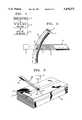
- FIGS. 2 and 3illustrate glass bodies upon which the process of FIG. 1 can be used
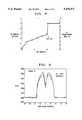
- FIGS. 4-9are graphical illustrations demonstrating the effect of the process in altering the index of refraction.
- FIG. 1illustrates the steps of an exemplary process for increasing the index of refraction of a local region of a glass body.
- the first stepis to provide a body of glass.
- the bodycan be any of a wide variety of forms. Forms particularly preferred for this process are illustrated in FIGS. 2 and 3. They include optical fiber (FIG. 2) and substrate-supported thin layers for planar optical waveguide devices (FIG. 3).
- the glassis a transparent glass doped with germanium such as GeO 2 doped silica.
- germaniumsuch as GeO 2 doped silica.
- the methodhas been found to work in other types of transparent glass such as phosphorus doped silica.
- Typical GeO 2 concentrations in silicaare in the range 3-20 mole % GeO 2 , with higher index changes observed for higher GeO 2 , concentrations.
- Typical P 2 O 5 concentrations in silicaare in the range 3-10 mole %.
- the next step shown in FIG. 1Bis to diffuse hydrogen (or deuterium) into the glass body at least in those regions whose refractive index is to be increased.
- this diffusionis effected by exposing the body to hydrogen or deuterium gas at a pressure in the range 14-11,000 p.s.i.
- the diffusiontakes place at low to moderate temperatures in the range 21°-250° C.
- Diffusion timesdepend on the temperature and the thickness of the glass to be loaded. Typical diffusion times for standard sized optical fibers vary from about 12 days at 21° C. to about 10 hours at 100° C. More generally, the time required for the H 2 loading of a fiber of radius r is proportional to r 2 and inversely proportional to the diffusivity of H 2 in the glass.
- the radiation induced reactionsusually occur only at localized portions of the glass body, it is possible to make use of H 2 that can diffuse from surrounding areas. For example, for a single mode fiber a significant amount of H 2 can diffuse from the cladding material into the GeO 2 doped core, thus permitting maximum index changes to be achieved in the core even though the H 2 concentration may be less than the GeO 2 concentration. It is believed that the pertinent reaction involves at least one H atom per Ge atom. In fabrication, the amount of loaded hydrogen at equilibrium varies jointly with the pressure of hydrogen and jointly with an exponential factor exp ##EQU1##
- the third step shown in FIG. 1Cis to heat the hydrogen-loaded glass and simultaneously apply actinic radiation to the region whose refractive index is to be increased.
- the glassis heated rapidly to a temperature in excess of 150° C. and even more preferably to a temperature in the range 200° C. to 450° C.
- the glass bodycan be heated by any method for rapid heating. Preferably it is heated by infrared radiation from a CO 2 laser. The heating can be general or local.
- the actinic radiationis preferably ultraviolet radiation, as from an excimer laser. It can be pulsed or continuous wave.
- the period for simultaneous exposurecan be less than the period required for out-diffusion of hydrogen from the glass at the temperature used (e.g. less than 14 mins. at 250° C. and less than 1.8 mins at 400° C.). Longer exposures to heat, actinic radiation or both can be used, but only with diminished marginal effect on the index of refraction. Additional heating, however, can enhance the long term stability of the UV-induced index changes.
- An optical waveguidetypically comprises an elongated glass structure including a core of relatively high refractive index glass and a cladding of lower refractive index glass at least partially surrounding the core.
- the dimensions of the coreare chosen and adapted for transmitting in the longitudinal direction electromagnetic radiation of optical wavelength typically in the range 0.8 to 1.7 micrometers.
- FIG. 2illustrates such a waveguiding body in the form of an optical fiber 10 having a cylindrical core 11 surrounded by a concentric cladding 12.
- the coreis typically germanium-doped silica.
- a convenient way of applying heat to a region 13 of said fiberis to apply infrared radiation 16 from a line focussed CO 2 laser 17.
- the actinic radiatione.g. UV radiation
- a UV source 14is simultaneously applied from a UV source 14 to heated region 13 in a pattern with periodic intensity peaks 15 to form a photoinduced grating.
- Such patterned exposurecan be achieved by use of interfering beams, an amplitude mask, or a phase mask as described in the aforementioned '427, '110, '209, and '515 patents.
- FIG. 3illustrates a waveguiding body in planar form, typically comprising a substrate 20, a thin cladding layer 21 disposed upon the substrate, a core glass layer 22 on the cladding and a top cladding layer 23.
- Planar waveguides for communications applicationstypically have phosphorus-doped silica cores. The basic structure of conventional planar waveguides is described in C. H. Henry et al., "Glass Waveguides On Silicon For Hybrid Optical Packaging", 7 J. Lightwave Technol., pp. 1530-39 (1989). Typically, all but a thin stripe of the core layer is etched away prior to application of the top cladding in order to define the waveguiding region.
- a convenient way to heat selected regions of the planar waveguide structureis to direct a laser 24, such as a CO 2 laser, to apply infrared radiation 25 onto a portion 26 of the structure.
- a laser 24such as a CO 2 laser
- the actinic radiatione.g. UV radiation from an excimer laser
- the actinic radiationis simultaneously applied from source 14 to heated region 26 in a pattern with intensity peaks 15 to form a photoinduced grating.
- Another advantageous applicationis to apply uniform UV radiation to a heated region of a waveguide or existing grating in order to adjust the average refractive index of the device.
- optical fiberswere loaded with molecular hydrogen or deuterium. Control experiments were done using identical fibers without hydrogen loading. Hydrogen or deuterium loading was typically done at about 440 atm and 50° C. over a time span of about 3-4 days. The hydrogen loading forces H 2 molecules into interstitial sites in the glass. The diffusion process is substantially reversible--if the fibers are not UV exposed or heated, the H 2 diffuses out of the fiber over the course of several days at room temperature.
- Pulsed UV exposureswere typically done using a KrF laser operating at 248 nm.
- the lasergenerated 15 nsec pulses, typically at 20 Hz.
- the intensitywas typically in the range of 160-450 mJ/cm 2 /pulse, with a typical irradiated fiber length of about 10-25 min.
- the experiments involving CW ultraviolet irradiationused an intracavity frequency-doubled argon laser operating at 244 nm with an output of up to about 150 mW. (Coherent Innova 300 FReD.)
- the active heating of the fiberswas done by directing a hot air gun at the fiber while it was being exposed to the UV.
- Temperatureswere measured using a small thermocouple positioned next to the fiber. The duration of the exposures were dictated by hydrogen diffusivities at the elevated temperatures. For instance, at 250° C. the time required for H 2 to diffuse out of the fiber core is about 14 minutes, with about half of the hydrogen leaving the core in only 5 minutes. UV exposures were generally not run for times longer than that required to diffuse the H 2 out of the fiber core.
- loss changeswere measured during the UV exposures. From past experiments it was known that the induced Si--OH levels could be used to estimate the induced refractive index changes. The loss change measurements were done using either a white light source or an edge emitting LED, and an optical spectrum analyzer.
- Refractive index changeswere measured using a York fiber profiler.
- the profilercan be used to detect index changes as small as about 2 ⁇ 10 -4 .
- index changes less than about 5 ⁇ 10 -4several similar samples were measured to verify the values of the index changes.
- Samples of a standard AT&T 5D single mode fiberwere loaded with H 2 to a level of about 3.4 mole % (moles of H 2 per mole of SiO 2 ). Prior to UV exposure the fiber coating was removed and the fiber was positioned in the beam path of the KrF excimer laser. In the first experiment an H 2 loaded fiber was UV exposed at an estimated intensity of about 435 mJ/cm 2 /pulse. The exposed fiber length was 25 mm. Heat (when used) was supplied by a Master-Mite heat gun using a 340 W nozzle. The nozzle was about 25 mm away from the fiber and the air flow was directed downward onto the fiber. The temperature was about 250° C., but showed significant ( ⁇ 30° C.) variations over the UV exposed region.
- FIG. 4shows the OH growth as a function of time for the heated and for the unheated sample.
- the initial OH growth ratewas significantly enhanced by the heating.
- the OH growth saturated in the heated sampleafter about 3 minutes, due to depletion of the two "reactants"--Ge sites and dissolved H 2 .
- Ge sitestend to be depleted as the reaction proceeds and H 2 is lost both by reaction and by out-diffusion.
- FIG. 5shows the OH increases versus time for heated and unheated fibers. Again, the initial rate was clearly a strong function of the temperature. The OH level in the 400° C. fiber saturated after several minutes, consistent with a predicted time of about 1.8 minutes for 95% of the H 2 to diffuse out of the core. The initial growth rates at 250° and 400° C. were about 4.3 and 32 times higher than the rate in the unheated fiber, respectively.
- the refractive index profiles of the fibers from this experimentwere measured after the UV exposure. The index increases ( ⁇ n) in the unheated, 250° C. and 400° C. heated fibers were 0.0011, 0.0022 and 0.0028, respectively.
- FIGS. 6 and 7show the loss changes and refractive index profiles for fibers that were UV irradiated without direct heating and for fibers that were heated to 250° and 400° C. during the irradiation.
- the refractive index of the GeO 2 doped MCVD deposited claddingincreased significantly in the 400° C. heated sample, but showed little or no change in the sample that was UV irradiated without direct heating. Presumably the D 2 reaction rate in the lightly doped cladding was sufficiently low in the absence of heating that the cladding index changes were undetectably small.
- FIG. 8shows the OH growth during the experiment where a H 2 loaded tethered vehicle fiber was exposed to 120 mW of 244 nm CW radiation that was focussed to a spot about 1 mm ⁇ 150 ⁇ m. Without heating, the OH peak grew about 0.56 dB/mm in 10 minutes--a rate of roughly 0.06 dB/mm/min. Following this exposure the same section of fiber was heated to about 250° C. while continuing the UV irradiation.
- a multimode fiber doped solely with P 2 O 5was hydrogen loaded and then UV exposed (248 nm), both with and without heating. Heating, when used, was at 250° and 400° C. Index changes were below our detection limit for the UV exposed samples that were not directly heated. However, for the samples that were heated during the UV exposure there were discernable index increases of 0.0004 to 0.0007, at 250° and 400° C. respectively.
- FIG. 9shows a clear index increase in the P 2 O 5 doped core of a sample that was heated to 400° C. during the UV irradiation.
- the P 2 O 5 doped glassappears to have behavior that is qualitatively similar to that seen for GeO 2 doped glass--i.e. both show a thermally enhanced UV photosensitivity.
- the glasscan be doped with transition-metal dopants such as chromium oxide which will absorb ultraviolet radiation and produce local heating. In this event a single ultraviolet source can simultaneously provide both heating and actinic radiation.
Landscapes
- Chemical & Material Sciences (AREA)
- Physics & Mathematics (AREA)
- Life Sciences & Earth Sciences (AREA)
- Engineering & Computer Science (AREA)
- Geochemistry & Mineralogy (AREA)
- Organic Chemistry (AREA)
- Materials Engineering (AREA)
- Chemical Kinetics & Catalysis (AREA)
- General Chemical & Material Sciences (AREA)
- Optics & Photonics (AREA)
- General Life Sciences & Earth Sciences (AREA)
- General Physics & Mathematics (AREA)
- Microelectronics & Electronic Packaging (AREA)
- Thermal Sciences (AREA)
- Health & Medical Sciences (AREA)
- Toxicology (AREA)
- Electromagnetism (AREA)
- Optical Fibers, Optical Fiber Cores, And Optical Fiber Bundles (AREA)
- Optical Integrated Circuits (AREA)
- Glass Compositions (AREA)
- Surface Treatment Of Glass (AREA)
- Diffracting Gratings Or Hologram Optical Elements (AREA)
- Re-Forming, After-Treatment, Cutting And Transporting Of Glass Products (AREA)
- Glass Melting And Manufacturing (AREA)
Abstract
Description
Claims (9)
Priority Applications (4)
| Application Number | Priority Date | Filing Date | Title |
|---|---|---|---|
| US08/305,235US5478371A (en) | 1992-05-05 | 1994-09-13 | Method for producing photoinduced bragg gratings by irradiating a hydrogenated glass body in a heated state |
| EP95306212AEP0702252A1 (en) | 1994-09-13 | 1995-09-06 | Method for producing photo-induced bragg gratings |
| KR1019950029648AKR100382442B1 (en) | 1994-09-13 | 1995-09-12 | Method for producing photoinduced bragg gratings |
| JP25821995AJP3371048B2 (en) | 1994-09-13 | 1995-09-12 | Method of forming photo-induced Bragg grating |
Applications Claiming Priority (4)
| Application Number | Priority Date | Filing Date | Title |
|---|---|---|---|
| US07/878,802US5235659A (en) | 1992-05-05 | 1992-05-05 | Method of making an article comprising an optical waveguide |
| US08/010,237US5287427A (en) | 1992-05-05 | 1993-01-28 | Method of making an article comprising an optical component, and article comprising the component |
| US5632993A | 1993-04-30 | 1993-04-30 | |
| US08/305,235US5478371A (en) | 1992-05-05 | 1994-09-13 | Method for producing photoinduced bragg gratings by irradiating a hydrogenated glass body in a heated state |
Related Parent Applications (1)
| Application Number | Title | Priority Date | Filing Date |
|---|---|---|---|
| US5632993AContinuation-In-Part | 1992-05-05 | 1993-04-30 |
Publications (1)
| Publication Number | Publication Date |
|---|---|
| US5478371Atrue US5478371A (en) | 1995-12-26 |
Family
ID=23179940
Family Applications (1)
| Application Number | Title | Priority Date | Filing Date |
|---|---|---|---|
| US08/305,235Expired - LifetimeUS5478371A (en) | 1992-05-05 | 1994-09-13 | Method for producing photoinduced bragg gratings by irradiating a hydrogenated glass body in a heated state |
Country Status (4)
| Country | Link |
|---|---|
| US (1) | US5478371A (en) |
| EP (1) | EP0702252A1 (en) |
| JP (1) | JP3371048B2 (en) |
| KR (1) | KR100382442B1 (en) |
Cited By (48)
| Publication number | Priority date | Publication date | Assignee | Title |
|---|---|---|---|---|
| US5620495A (en)* | 1995-08-16 | 1997-04-15 | Lucent Technologies Inc. | Formation of gratings in polymer-coated optical fibers |
| US5670280A (en)* | 1996-05-30 | 1997-09-23 | Brown University Research Foundation | Optically controlled imaging phase mask element |
| WO1998006001A1 (en)* | 1996-08-07 | 1998-02-12 | Corning Incorporated | Optical waveguide fiber bragg grating |
| US5763340A (en)* | 1996-01-19 | 1998-06-09 | Agency Of Industrial Science & Technology, Ministry Of International Trade & Industry | Method for production of SiO2 glass material having regions changed in light refractive index and SiO2 glass material produced by the method |
| US5881187A (en)* | 1997-07-29 | 1999-03-09 | Corning Incorporated | Optical waveguide fiber bragg grating |
| EP0880719A4 (en)* | 1996-02-15 | 1999-03-24 | Corning Inc | Method of making a symmetrical optical waveguide |
| US5930420A (en)* | 1997-08-15 | 1999-07-27 | Lucent Technologies, Inc. | Method for producing photo induced grating devices by UV irradiation of heat-activated hydrogenated glass |
| US6058739A (en)* | 1998-10-29 | 2000-05-09 | Cymer, Inc. | Long life fused silica ultraviolet optical elements |
| WO2000057225A1 (en)* | 1999-03-25 | 2000-09-28 | Acme Grating Ventures, Llc | Optical systems and apparatuses including bragg gratings and methods of making |
| US6192712B1 (en)* | 1997-03-05 | 2001-02-27 | Nec Corporation | Optical waveguide fabrication method |
| US6209356B1 (en)* | 1995-02-23 | 2001-04-03 | Agilent Technologies, Inc. | Method of making polarization-maintaining optical fibers |
| US6220059B1 (en)* | 1995-12-21 | 2001-04-24 | Heraeus Quarzglas Gmbh | Method of coating a UV-fiber with blocking layers and charging the fiber with hydrogen or deuterium |
| US6221566B1 (en)* | 1999-02-18 | 2001-04-24 | Corning Incorporated | Optical waveguide photosensitization |
| US6233381B1 (en)* | 1997-07-25 | 2001-05-15 | Corning Incorporated | Photoinduced grating in oxynitride glass |
| US6246815B1 (en) | 1996-08-12 | 2001-06-12 | Toyota Jidosha Kabushiki Kaisha | Grating element, light wavelength selection utilizing the same, and optical signal transmitting system |
| US20010035029A1 (en)* | 1999-07-12 | 2001-11-01 | Akira Ikushima | Method of manufacturing an optical fiber |
| US6374026B1 (en) | 1996-09-17 | 2002-04-16 | Toyota Jidosha Kabushiki Kaisha | Manufacture of planar waveguide and planar waveguide |
| US20020114568A1 (en)* | 2000-12-15 | 2002-08-22 | Judkins Robert O. | Optical fiber termination collimator and process of manufacture |
| US6442312B1 (en)* | 1997-07-08 | 2002-08-27 | Oki Electric Industry Co., Ltd. | Optical filter fabrication method and apparatus, optical filter, fiber holder with spiral groove, and phase mask |
| US6459829B1 (en) | 1999-02-10 | 2002-10-01 | Ryozo Yamauchi | Multiple wavelength excitation optical multiplexing device, multiple wavelength excitation light source incorporating aforementioned device, and optical amplifier |
| US6518078B2 (en)* | 1998-09-21 | 2003-02-11 | California Institute Of Technology | Articles useful as optical waveguides and method for manufacturing same |
| US20030039747A1 (en)* | 2001-08-27 | 2003-02-27 | Optinel Systems,Inc. | Method of enhancing waveguide photosensitivity and waveguide having enhanced photosensitivity |
| US6549706B2 (en)* | 1997-07-25 | 2003-04-15 | Corning Incorporated | Photoinduced grating in oxynitride glass |
| US6580854B1 (en)* | 1998-01-19 | 2003-06-17 | Sumitomo Electric Industries, Ltd. | Optical waveguide grating and method of making the same |
| US20030115911A1 (en)* | 2001-12-20 | 2003-06-26 | Carpenter James B. | Apparatus for selective photosensitization of optical fiber |
| US20030121289A1 (en)* | 2002-01-02 | 2003-07-03 | Benda John A. | Long period fiber Bragg gratings written with alternate side IR laser illumination |
| US6588236B2 (en) | 1999-07-12 | 2003-07-08 | Kitagawa Industries Co., Ltd. | Method of processing a silica glass fiber by irradiating with UV light and annealing |
| US20030185533A1 (en)* | 1999-10-15 | 2003-10-02 | California Institute Of Technology, A California Non-Profit Corporation | Titanium-indiffusion waveguides and methods of fabrication |
| US6631232B1 (en)* | 2002-05-07 | 2003-10-07 | Itf Optical Technologies Inc. | Adjustment of thermal dependence of an optical fiber |
| US6647167B1 (en) | 2000-10-31 | 2003-11-11 | Lightwave Technologies, Inc. | Solid state optical switch and router |
| US20040011081A1 (en)* | 2001-06-26 | 2004-01-22 | Chang Kai H. | Method and apparatus for fabricating optical fiber using deuterium exposure |
| US6708741B1 (en) | 2000-08-24 | 2004-03-23 | Ocean Spray Cranberries, Inc. | Beverage dispenser |
| US6763686B2 (en)* | 1996-10-23 | 2004-07-20 | 3M Innovative Properties Company | Method for selective photosensitization of optical fiber |
| US20040139766A1 (en)* | 2003-01-17 | 2004-07-22 | Weeks Gene K. | Systems and methods for recycling gas used in treating optical fiber |
| KR100475419B1 (en)* | 2002-09-04 | 2005-03-10 | (주)한울옵틱스 | Method for fabrication of optical terminator having reflection light terminated function |
| US20050130340A1 (en)* | 2003-12-12 | 2005-06-16 | Claude Beaulieu | Method and apparatus for inducing an index of refraction change on a substrate sensitive to electromagnetic radiation |
| US6931215B1 (en)* | 2000-06-26 | 2005-08-16 | Hitachi, Ltd. | Optical transmitter module |
| US20060248925A1 (en)* | 2005-04-06 | 2006-11-09 | Sanders Paul E | Conditioning optical fibers for improved ionizing radiation response |
| EP1576395A4 (en)* | 2002-11-26 | 2007-02-14 | 3Sae Technologies Inc | Hydrogen concentration relocation in optical fiber |
| US20080190146A1 (en)* | 2002-05-17 | 2008-08-14 | Sumitomo Electric Industries, Ltd. | Optical fiber bundle and method of manufacture the same |
| US20090103874A1 (en)* | 2006-03-17 | 2009-04-23 | Crystal Fibre A/S | Optical fiber, a fiber laser, a fiber amplifier and articles comprising such elements |
| US7526160B1 (en) | 2007-12-20 | 2009-04-28 | Baker Hughes Incorporated | Optical fiber Bragg grating with improved hydrogen resistance |
| US20100148383A1 (en)* | 2008-12-15 | 2010-06-17 | Ofs Fitel, Llc | Method of controlling longitudinal properties of optical fiber |
| US20150068251A1 (en)* | 2013-08-30 | 2015-03-12 | Schott Ag | Method for drawing glass strips |
| US9002152B2 (en) | 2010-05-04 | 2015-04-07 | Sensortran, Inc. | Mitigation of radiation induced attenuation |
| US11261121B2 (en)* | 2017-10-20 | 2022-03-01 | Corning Incorporated | Optical fiber preforms with halogen doping |
| US20220227657A1 (en)* | 2019-06-12 | 2022-07-21 | Leoni Kabel Gmbh | Quartz fibre with hydrogen barrier layer and method for the production thereof |
| US12164144B2 (en) | 2020-05-13 | 2024-12-10 | National Research Council Of Canada | Fiber Bragg grating sensor in polymer-coated ultra-thin optical fibers and method for producing same |
Families Citing this family (7)
| Publication number | Priority date | Publication date | Assignee | Title |
|---|---|---|---|---|
| US5938811A (en)* | 1997-05-23 | 1999-08-17 | Lucent Technologies Inc. | Method for altering the temperature dependence of optical waveguides devices |
| DE69914315T2 (en) | 1998-03-12 | 2004-11-25 | Toyota Jidosha K.K., Toyota | METHOD FOR PRODUCING OPTICALLY NONLINEAR THIN FILM WAVE LADDERS AND OPTICALLY NONLINEAR THIN FILM WAVE LADDER |
| KR100333897B1 (en) | 1998-06-24 | 2002-07-31 | 광주과학기술원 | Stress-Relieved Long-Range Optical Fiber Grids |
| DE19849612A1 (en)* | 1998-10-28 | 2000-05-04 | Alcatel Sa | Planar optical waveguide has region of glass layer in which refractive index is locally increased with respect to surrounding regions |
| EP1180247A1 (en)* | 1999-02-26 | 2002-02-20 | Ionas A/S | An apparatus and a method for changing refractive index |
| WO2008028277A1 (en) | 2006-09-08 | 2008-03-13 | Lxsix Photonics Inc. | Optical device for measuring a physical parameter in a hydrogen contaminated sensing zone |
| JP4950932B2 (en)* | 2007-04-12 | 2012-06-13 | タツタ電線株式会社 | Annealing method for optical fiber grating |
Citations (12)
| Publication number | Priority date | Publication date | Assignee | Title |
|---|---|---|---|---|
| US4474427A (en)* | 1979-05-07 | 1984-10-02 | Canadian Patents & Development Limited | Optical fiber reflective filter |
| US4504297A (en)* | 1983-07-06 | 1985-03-12 | At&T Bell Laboratories | Optical fiber preform manufacturing method |
| US4725110A (en)* | 1984-08-13 | 1988-02-16 | United Technologies Corporation | Method for impressing gratings within fiber optics |
| US4856859A (en)* | 1987-03-13 | 1989-08-15 | Hitachi, Ltd. | Optical waveguide and method for fabricating the same |
| US4979976A (en)* | 1990-04-16 | 1990-12-25 | Corning Incorporated | Making colored photochromic glasses |
| US5104209A (en)* | 1991-02-19 | 1992-04-14 | Her Majesty The Queen In Right Of Canada, As Represented By The Minister Of Communications | Method of creating an index grating in an optical fiber and a mode converter using the index grating |
| US5235659A (en)* | 1992-05-05 | 1993-08-10 | At&T Bell Laboratories | Method of making an article comprising an optical waveguide |
| US5267343A (en)* | 1992-09-03 | 1993-11-30 | The United States Of America As Represented By The United States Department Of Energy | Enhanced radiation resistant fiber optics |
| US5271024A (en)* | 1992-07-27 | 1993-12-14 | General Instrument Corporation | Optical fiber amplifier and laser with flattened gain slope |
| US5287427A (en)* | 1992-05-05 | 1994-02-15 | At&T Bell Laboratories | Method of making an article comprising an optical component, and article comprising the component |
| US5327515A (en)* | 1993-01-14 | 1994-07-05 | At&T Laboratories | Method for forming a Bragg grating in an optical medium |
| US5367588A (en)* | 1992-10-29 | 1994-11-22 | Her Majesty The Queen In Right Of Canada, As Represented By The Minister Of Communications | Method of fabricating Bragg gratings using a silica glass phase grating mask and mask used by same |
Family Cites Families (1)
| Publication number | Priority date | Publication date | Assignee | Title |
|---|---|---|---|---|
| US563293A (en) | 1896-07-07 | Glass-tank furnace |
- 1994
- 1994-09-13USUS08/305,235patent/US5478371A/ennot_activeExpired - Lifetime
- 1995
- 1995-09-06EPEP95306212Apatent/EP0702252A1/ennot_activeWithdrawn
- 1995-09-12JPJP25821995Apatent/JP3371048B2/ennot_activeExpired - Lifetime
- 1995-09-12KRKR1019950029648Apatent/KR100382442B1/ennot_activeExpired - Lifetime
Patent Citations (12)
| Publication number | Priority date | Publication date | Assignee | Title |
|---|---|---|---|---|
| US4474427A (en)* | 1979-05-07 | 1984-10-02 | Canadian Patents & Development Limited | Optical fiber reflective filter |
| US4504297A (en)* | 1983-07-06 | 1985-03-12 | At&T Bell Laboratories | Optical fiber preform manufacturing method |
| US4725110A (en)* | 1984-08-13 | 1988-02-16 | United Technologies Corporation | Method for impressing gratings within fiber optics |
| US4856859A (en)* | 1987-03-13 | 1989-08-15 | Hitachi, Ltd. | Optical waveguide and method for fabricating the same |
| US4979976A (en)* | 1990-04-16 | 1990-12-25 | Corning Incorporated | Making colored photochromic glasses |
| US5104209A (en)* | 1991-02-19 | 1992-04-14 | Her Majesty The Queen In Right Of Canada, As Represented By The Minister Of Communications | Method of creating an index grating in an optical fiber and a mode converter using the index grating |
| US5235659A (en)* | 1992-05-05 | 1993-08-10 | At&T Bell Laboratories | Method of making an article comprising an optical waveguide |
| US5287427A (en)* | 1992-05-05 | 1994-02-15 | At&T Bell Laboratories | Method of making an article comprising an optical component, and article comprising the component |
| US5271024A (en)* | 1992-07-27 | 1993-12-14 | General Instrument Corporation | Optical fiber amplifier and laser with flattened gain slope |
| US5267343A (en)* | 1992-09-03 | 1993-11-30 | The United States Of America As Represented By The United States Department Of Energy | Enhanced radiation resistant fiber optics |
| US5367588A (en)* | 1992-10-29 | 1994-11-22 | Her Majesty The Queen In Right Of Canada, As Represented By The Minister Of Communications | Method of fabricating Bragg gratings using a silica glass phase grating mask and mask used by same |
| US5327515A (en)* | 1993-01-14 | 1994-07-05 | At&T Laboratories | Method for forming a Bragg grating in an optical medium |
Non-Patent Citations (5)
| Title |
|---|
| G. D. Maxwell, et al. "UV written 13dB Reflection Filters in Hydrogenated Low Loss Planar Silica Waveguides", Electronics Letters, vol. 29, No. 5, pp. 425-426 (1993). |
| G. D. Maxwell, et al. UV written 13dB Reflection Filters in Hydrogenated Low Loss Planar Silica Waveguides , Electronics Letters, vol. 29, No. 5, pp. 425 426 (1993).* |
| R. M. Atkins, et al. "Effects of elevated temperature hydrogen exposure on short-wavelength optical losses and defect concentrations in germanosilicate optical fibers", J. Appl. Phys., vol. 72, pp. 344-348 (1992). |
| R. M. Atkins, et al. Effects of elevated temperature hydrogen exposure on short wavelength optical losses and defect concentrations in germanosilicate optical fibers , J. Appl. Phys., vol. 72, pp. 344 348 (1992).* |
| Translation of West German Patent No. 2,843,276, issued in W. Germany on Sep. 1979 to Siemens.* |
Cited By (66)
| Publication number | Priority date | Publication date | Assignee | Title |
|---|---|---|---|---|
| US6209356B1 (en)* | 1995-02-23 | 2001-04-03 | Agilent Technologies, Inc. | Method of making polarization-maintaining optical fibers |
| US5620495A (en)* | 1995-08-16 | 1997-04-15 | Lucent Technologies Inc. | Formation of gratings in polymer-coated optical fibers |
| US6220059B1 (en)* | 1995-12-21 | 2001-04-24 | Heraeus Quarzglas Gmbh | Method of coating a UV-fiber with blocking layers and charging the fiber with hydrogen or deuterium |
| US5763340A (en)* | 1996-01-19 | 1998-06-09 | Agency Of Industrial Science & Technology, Ministry Of International Trade & Industry | Method for production of SiO2 glass material having regions changed in light refractive index and SiO2 glass material produced by the method |
| EP0880719A4 (en)* | 1996-02-15 | 1999-03-24 | Corning Inc | Method of making a symmetrical optical waveguide |
| US5670280A (en)* | 1996-05-30 | 1997-09-23 | Brown University Research Foundation | Optically controlled imaging phase mask element |
| WO1998006001A1 (en)* | 1996-08-07 | 1998-02-12 | Corning Incorporated | Optical waveguide fiber bragg grating |
| US6246815B1 (en) | 1996-08-12 | 2001-06-12 | Toyota Jidosha Kabushiki Kaisha | Grating element, light wavelength selection utilizing the same, and optical signal transmitting system |
| US6374026B1 (en) | 1996-09-17 | 2002-04-16 | Toyota Jidosha Kabushiki Kaisha | Manufacture of planar waveguide and planar waveguide |
| US6763686B2 (en)* | 1996-10-23 | 2004-07-20 | 3M Innovative Properties Company | Method for selective photosensitization of optical fiber |
| US6192712B1 (en)* | 1997-03-05 | 2001-02-27 | Nec Corporation | Optical waveguide fabrication method |
| EP0890851A3 (en)* | 1997-07-08 | 2003-06-04 | Oki Electric Industry Co., Ltd. | Optical filter fabrication method and apparatus, optical filter, fiber holder with spiral groove, and phase mask |
| US6442312B1 (en)* | 1997-07-08 | 2002-08-27 | Oki Electric Industry Co., Ltd. | Optical filter fabrication method and apparatus, optical filter, fiber holder with spiral groove, and phase mask |
| US6653051B2 (en)* | 1997-07-25 | 2003-11-25 | Corning Incorporated | Photoinduced grating in oxynitride glass |
| US6233381B1 (en)* | 1997-07-25 | 2001-05-15 | Corning Incorporated | Photoinduced grating in oxynitride glass |
| US6549706B2 (en)* | 1997-07-25 | 2003-04-15 | Corning Incorporated | Photoinduced grating in oxynitride glass |
| US5881187A (en)* | 1997-07-29 | 1999-03-09 | Corning Incorporated | Optical waveguide fiber bragg grating |
| US5930420A (en)* | 1997-08-15 | 1999-07-27 | Lucent Technologies, Inc. | Method for producing photo induced grating devices by UV irradiation of heat-activated hydrogenated glass |
| US6580854B1 (en)* | 1998-01-19 | 2003-06-17 | Sumitomo Electric Industries, Ltd. | Optical waveguide grating and method of making the same |
| US6898365B2 (en) | 1998-09-21 | 2005-05-24 | California Institute Of Technology | Articles useful as optical waveguides and method for manufacturing same |
| US6518078B2 (en)* | 1998-09-21 | 2003-02-11 | California Institute Of Technology | Articles useful as optical waveguides and method for manufacturing same |
| US6058739A (en)* | 1998-10-29 | 2000-05-09 | Cymer, Inc. | Long life fused silica ultraviolet optical elements |
| US6459829B1 (en) | 1999-02-10 | 2002-10-01 | Ryozo Yamauchi | Multiple wavelength excitation optical multiplexing device, multiple wavelength excitation light source incorporating aforementioned device, and optical amplifier |
| US6221566B1 (en)* | 1999-02-18 | 2001-04-24 | Corning Incorporated | Optical waveguide photosensitization |
| US6702897B2 (en) | 1999-03-25 | 2004-03-09 | Acme Grating Ventures, Llc | Optical transmission systems and apparatuses including bragg gratings and methods of making |
| US6238729B1 (en) | 1999-03-25 | 2001-05-29 | Acme Grating Ventures, Llc | Optical transmission systems and apparatuses including bragg gratings and methods of making |
| US6238485B1 (en) | 1999-03-25 | 2001-05-29 | Acme Grating Ventures, Llc | Optical transmission systems and apparatuses including bragg gratings and methods of making |
| WO2000057225A1 (en)* | 1999-03-25 | 2000-09-28 | Acme Grating Ventures, Llc | Optical systems and apparatuses including bragg gratings and methods of making |
| US6327406B1 (en) | 1999-03-25 | 2001-12-04 | Acme Grating Ventures, Llc | Optical transmission systems and apparatuses including Bragg gratings and methods of making |
| US20010035029A1 (en)* | 1999-07-12 | 2001-11-01 | Akira Ikushima | Method of manufacturing an optical fiber |
| US6588236B2 (en) | 1999-07-12 | 2003-07-08 | Kitagawa Industries Co., Ltd. | Method of processing a silica glass fiber by irradiating with UV light and annealing |
| US6856746B2 (en) | 1999-10-15 | 2005-02-15 | California Institute Of Technology | Titanium-indiffusion waveguides and methods of fabrication |
| US20030185533A1 (en)* | 1999-10-15 | 2003-10-02 | California Institute Of Technology, A California Non-Profit Corporation | Titanium-indiffusion waveguides and methods of fabrication |
| US6931215B1 (en)* | 2000-06-26 | 2005-08-16 | Hitachi, Ltd. | Optical transmitter module |
| US6708741B1 (en) | 2000-08-24 | 2004-03-23 | Ocean Spray Cranberries, Inc. | Beverage dispenser |
| US6647167B1 (en) | 2000-10-31 | 2003-11-11 | Lightwave Technologies, Inc. | Solid state optical switch and router |
| US20020114568A1 (en)* | 2000-12-15 | 2002-08-22 | Judkins Robert O. | Optical fiber termination collimator and process of manufacture |
| US7546750B2 (en)* | 2001-06-26 | 2009-06-16 | Fitel Usa Corp. | Method for fabricating optical fiber using deuterium exposure |
| US20040011081A1 (en)* | 2001-06-26 | 2004-01-22 | Chang Kai H. | Method and apparatus for fabricating optical fiber using deuterium exposure |
| US20030039747A1 (en)* | 2001-08-27 | 2003-02-27 | Optinel Systems,Inc. | Method of enhancing waveguide photosensitivity and waveguide having enhanced photosensitivity |
| US20030115911A1 (en)* | 2001-12-20 | 2003-06-26 | Carpenter James B. | Apparatus for selective photosensitization of optical fiber |
| US6857293B2 (en)* | 2001-12-20 | 2005-02-22 | 3M Innovative Properties Company | Apparatus for selective photosensitization of optical fiber |
| US20030121289A1 (en)* | 2002-01-02 | 2003-07-03 | Benda John A. | Long period fiber Bragg gratings written with alternate side IR laser illumination |
| US7946137B2 (en)* | 2002-01-02 | 2011-05-24 | United Technologies Corporation | Long period fiber Bragg gratings written with alternate side IR laser illumination |
| US20050204779A1 (en)* | 2002-01-02 | 2005-09-22 | Benda John A | Long period fiber bragg gratings written with alternate side IR laser illumination |
| US20050217321A1 (en)* | 2002-01-02 | 2005-10-06 | Benda John A | Long period fiber Bragg gratings written with alternate side IR laser illumination |
| US6631232B1 (en)* | 2002-05-07 | 2003-10-07 | Itf Optical Technologies Inc. | Adjustment of thermal dependence of an optical fiber |
| US20080190146A1 (en)* | 2002-05-17 | 2008-08-14 | Sumitomo Electric Industries, Ltd. | Optical fiber bundle and method of manufacture the same |
| KR100475419B1 (en)* | 2002-09-04 | 2005-03-10 | (주)한울옵틱스 | Method for fabrication of optical terminator having reflection light terminated function |
| EP1576395A4 (en)* | 2002-11-26 | 2007-02-14 | 3Sae Technologies Inc | Hydrogen concentration relocation in optical fiber |
| US20040139766A1 (en)* | 2003-01-17 | 2004-07-22 | Weeks Gene K. | Systems and methods for recycling gas used in treating optical fiber |
| US20070147737A1 (en)* | 2003-12-12 | 2007-06-28 | Lxsix Photonics Inc. | Method and apparatus for inducing an index of refraction change on a substrate sensitive to electromagnetic radiation |
| US20050130340A1 (en)* | 2003-12-12 | 2005-06-16 | Claude Beaulieu | Method and apparatus for inducing an index of refraction change on a substrate sensitive to electromagnetic radiation |
| US7418162B2 (en) | 2003-12-12 | 2008-08-26 | Lxsix Photonics Inc. | Method and apparatus for inducing an index of refraction change on a substrate sensitive to electromagnetic radiation |
| US7277604B2 (en) | 2003-12-12 | 2007-10-02 | Lxsix Photonics Inc. | Method and apparatus for inducing an index of refraction change on a substrate sensitive to electromagnetic radiation |
| US20060248925A1 (en)* | 2005-04-06 | 2006-11-09 | Sanders Paul E | Conditioning optical fibers for improved ionizing radiation response |
| US20090103874A1 (en)* | 2006-03-17 | 2009-04-23 | Crystal Fibre A/S | Optical fiber, a fiber laser, a fiber amplifier and articles comprising such elements |
| US7526160B1 (en) | 2007-12-20 | 2009-04-28 | Baker Hughes Incorporated | Optical fiber Bragg grating with improved hydrogen resistance |
| US20100148383A1 (en)* | 2008-12-15 | 2010-06-17 | Ofs Fitel, Llc | Method of controlling longitudinal properties of optical fiber |
| US8591777B2 (en)* | 2008-12-15 | 2013-11-26 | Ofs Fitel, Llc | Method of controlling longitudinal properties of optical fiber |
| US9002152B2 (en) | 2010-05-04 | 2015-04-07 | Sensortran, Inc. | Mitigation of radiation induced attenuation |
| US20150068251A1 (en)* | 2013-08-30 | 2015-03-12 | Schott Ag | Method for drawing glass strips |
| US11261121B2 (en)* | 2017-10-20 | 2022-03-01 | Corning Incorporated | Optical fiber preforms with halogen doping |
| US20220227657A1 (en)* | 2019-06-12 | 2022-07-21 | Leoni Kabel Gmbh | Quartz fibre with hydrogen barrier layer and method for the production thereof |
| US12252431B2 (en)* | 2019-06-12 | 2025-03-18 | J-Fiber Gmbh | Quartz fibre with hydrogen barrier layer and method for the production thereof |
| US12164144B2 (en) | 2020-05-13 | 2024-12-10 | National Research Council Of Canada | Fiber Bragg grating sensor in polymer-coated ultra-thin optical fibers and method for producing same |
Also Published As
| Publication number | Publication date |
|---|---|
| KR960010562A (en) | 1996-04-20 |
| JPH0881231A (en) | 1996-03-26 |
| EP0702252A1 (en) | 1996-03-20 |
| KR100382442B1 (en) | 2003-09-19 |
| JP3371048B2 (en) | 2003-01-27 |
Similar Documents
| Publication | Publication Date | Title |
|---|---|---|
| US5478371A (en) | Method for producing photoinduced bragg gratings by irradiating a hydrogenated glass body in a heated state | |
| US5500031A (en) | Method for increasing the index of refraction of a glassy material | |
| US5930420A (en) | Method for producing photo induced grating devices by UV irradiation of heat-activated hydrogenated glass | |
| US5287427A (en) | Method of making an article comprising an optical component, and article comprising the component | |
| US5495548A (en) | Photosensitization of optical fiber and silica waveguides | |
| US5235659A (en) | Method of making an article comprising an optical waveguide | |
| KR100351218B1 (en) | Method for making stable optical devices employing radiation-induced index changes | |
| US6221566B1 (en) | Optical waveguide photosensitization | |
| US6160944A (en) | Optical waveguide device | |
| Niay et al. | Behaviour of spectral transmissions of Bragg gratings written in germania-doped fibres: writing and erasing experiments using pulsed or cw uv exposure | |
| US8067755B2 (en) | Production device and production method for an optical device component having a grating structure | |
| KR20000036204A (en) | Optical means | |
| US6226433B1 (en) | Planar optical waveguide and method of spatially selectively increasing the refractive index in a glass | |
| EP0622343B1 (en) | Method for increasing the index of refraction of a glassy material | |
| US7704682B2 (en) | Optical fiber having bragg grating and method of manufacturing the same | |
| Nikogosyan | Long-period gratings in a standard telecom fibre fabricated by high-intensity femtosecond UV and near-UV laser pulses | |
| JP3011308B2 (en) | Manufacturing method of optical fiber with increased photosensitivity. | |
| Dianov et al. | Dynamics of the refractive index induced in germanosilicate optical fibres by different types of UV irradiation | |
| US5588085A (en) | Radiolytic method for making a mode-field transforming optical waveguide | |
| AU678892B2 (en) | Optical grating | |
| Slattery et al. | High-intensity UV laser inscription of fibre Bragg gratings and comparison with other fabrication techniques | |
| Zhang | Photosensitivity and Bragg gratings in optical fibers | |
| JPH08286013A (en) | Method for manufacturing optical waveguide type diffraction grating | |
| Yu et al. | Transmission spectra dependence on the grating lengths of long period fiber grating fabricated by 800nm femtosecond laser pulses | |
| Yongqin et al. | Transmission Spectra Dependence on the Grating Lengths of Long Period Fiber Grating Fabricated by 800 nm Femtosecond Laser Pulses |
Legal Events
| Date | Code | Title | Description |
|---|---|---|---|
| AS | Assignment | Owner name:AT&T CORP., NEW YORK Free format text:ASSIGNMENT OF ASSIGNORS INTEREST;ASSIGNORS:LEMAIRE, PAUL JOSEPH;REED, WILLIAM ALFRED;VENGSARKAR, ASHISH MADHUKAR;REEL/FRAME:007214/0564 Effective date:19941110 | |
| AS | Assignment | Owner name:AT&T IPM CORP., FLORIDA Free format text:ASSIGNMENT OF ASSIGNORS INTEREST;ASSIGNOR:AT&T CORP.;REEL/FRAME:007467/0511 Effective date:19950428 | |
| STCF | Information on status: patent grant | Free format text:PATENTED CASE | |
| FEPP | Fee payment procedure | Free format text:PAYOR NUMBER ASSIGNED (ORIGINAL EVENT CODE: ASPN); ENTITY STATUS OF PATENT OWNER: LARGE ENTITY | |
| FPAY | Fee payment | Year of fee payment:4 | |
| AS | Assignment | Owner name:LUCENT TECHNOLOGIES INC., NEW JERSEY Free format text:ASSIGNMENT OF ASSIGNORS INTEREST;ASSIGNOR:AT&T CORP.;REEL/FRAME:012059/0893 Effective date:19960329 | |
| AS | Assignment | Owner name:FITEL USA CORPORATION, GEORGIA Free format text:ASSIGNMENT OF ASSIGNORS INTEREST;ASSIGNOR:LUCENT TECHNOLOGIES;REEL/FRAME:012946/0578 Effective date:20011116 | |
| FPAY | Fee payment | Year of fee payment:8 | |
| REMI | Maintenance fee reminder mailed | ||
| FPAY | Fee payment | Year of fee payment:12 | |
| SULP | Surcharge for late payment | Year of fee payment:11 | |
| AS | Assignment | Owner name:FURUKAWA ELECTRIC NORTH AMERICA, INC., GEORGIA Free format text:CHANGE OF NAME;ASSIGNOR:FITEL USA CORP.;REEL/FRAME:025521/0684 Effective date:20031218 |