US5478258A - BNC connector and PC board arrangement - Google Patents
BNC connector and PC board arrangementDownload PDFInfo
- Publication number
- US5478258A US5478258AUS08/169,102US16910293AUS5478258AUS 5478258 AUS5478258 AUS 5478258AUS 16910293 AUS16910293 AUS 16910293AUS 5478258 AUS5478258 AUS 5478258A
- Authority
- US
- United States
- Prior art keywords
- printed circuit
- circuit board
- bnc connector
- insulative body
- elongated grooves
- Prior art date
- Legal status (The legal status is an assumption and is not a legal conclusion. Google has not performed a legal analysis and makes no representation as to the accuracy of the status listed.)
- Expired - Fee Related
Links
- 238000010079rubber tappingMethods0.000claimsabstractdescription6
- FPWNLURCHDRMHC-UHFFFAOYSA-N4-chlorobiphenylChemical compoundC1=CC(Cl)=CC=C1C1=CC=CC=C1FPWNLURCHDRMHC-UHFFFAOYSA-N0.000description14
- 239000002184metalSubstances0.000description12
- 239000003990capacitorSubstances0.000description4
- 238000009434installationMethods0.000description2
- 230000008878couplingEffects0.000description1
- 238000010168coupling processMethods0.000description1
- 238000005859coupling reactionMethods0.000description1
- 238000009713electroplatingMethods0.000description1
- 238000002955isolationMethods0.000description1
- 230000004048modificationEffects0.000description1
- 238000012986modificationMethods0.000description1
- 238000000465mouldingMethods0.000description1
- 229920003023plasticPolymers0.000description1
- 239000004033plasticSubstances0.000description1
- 238000003466weldingMethods0.000description1
Images


Classifications
- H—ELECTRICITY
- H01—ELECTRIC ELEMENTS
- H01R—ELECTRICALLY-CONDUCTIVE CONNECTIONS; STRUCTURAL ASSOCIATIONS OF A PLURALITY OF MUTUALLY-INSULATED ELECTRICAL CONNECTING ELEMENTS; COUPLING DEVICES; CURRENT COLLECTORS
- H01R24/00—Two-part coupling devices, or either of their cooperating parts, characterised by their overall structure
- H01R24/38—Two-part coupling devices, or either of their cooperating parts, characterised by their overall structure having concentrically or coaxially arranged contacts
- H01R24/40—Two-part coupling devices, or either of their cooperating parts, characterised by their overall structure having concentrically or coaxially arranged contacts specially adapted for high frequency
- H01R24/50—Two-part coupling devices, or either of their cooperating parts, characterised by their overall structure having concentrically or coaxially arranged contacts specially adapted for high frequency mounted on a PCB [Printed Circuit Board]
- H—ELECTRICITY
- H01—ELECTRIC ELEMENTS
- H01R—ELECTRICALLY-CONDUCTIVE CONNECTIONS; STRUCTURAL ASSOCIATIONS OF A PLURALITY OF MUTUALLY-INSULATED ELECTRICAL CONNECTING ELEMENTS; COUPLING DEVICES; CURRENT COLLECTORS
- H01R2103/00—Two poles
Definitions
- the present inventionrelates to an electrical connector for connecting a coaxial cable to a printed circuit board, and more particularly, to features of the connector providing wing portions to hold the printed circuit board.
- U.S. Pat. No. 4,797,120discloses a coaxial connector having filtered ground isolation means for mounting to a printed circuit board
- U.S. Pat. No. 4659,156discloses a coaxial connector with circuit board mounting features for the same purpose.
- U.S. Pat. No. 4,884,982discloses a capacitive coupled connector for the same purpose.
- These electrical connectorshave a common feature, i.e. each connector has two posts vertically disposed at the bottom for pluggable receipt into respective PCB apertures. When plugged into the PCB apertures, the posts are then welded to the PC board, as shown in FIG. 1.
- the whole assembly of the BNC connector(includes the insulative body and the BNC jack) is upstanding from the PC board at one side, therefore the BNC connector occupies much installation space at one side of the PC board, and the size of the outer shell which receives the PC board and the BNC connector must be relatively increased.
- the binding forceis weak, and the connection between the BNC connector and the PC board may be damaged easily.
- the present inventionhas been accomplished to provide a BNC connector and PC board arrangement which eliminates the aforesaid drawbacks.
- the BNC connector and PC board arrangementincludes a PC board having a rectangular side opening, and a BNC connector having an insulative body received in the rectangular side opening of the PC board, therefore the BNC connector has two opposite parts respectively disposed at two opposite sides relative to the PC board, and less installation space above the PC board is occupied.
- the BNC connectorcomprises two elongated grooves at two opposite sides, which receives the two opposite lateral sides of the rectangular side opening of the PC board, and two wing portions at two opposite sides, which respectively stop at the back side of the PC board and affixed thereto by self-tapping screws.
- capacitor elementsare mounted within top through holes on the insulative body and connected between the ground terminal of the BNC connector and a metal clip to form a filter circuit.
- FIG. 1is an elevational view of a prior art BNC connector installed in a printed circuit board
- FIG. 2is an elevational view of a BNC connector according to a first embodiment of the present invention
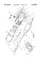
- FIG. 3is an exploded view of the BNC connector shown in FIG. 2;
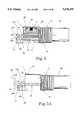
- FIG. 4is a longitudinal view in section of the BNC connector shown in FIG. 2;
- FIG. 5shows the BNC connector of FIG. 2 installed in a printed circuit board
- FIG. 5Ais a side view in section of FIG. 5;
- FIG. 6shows an alternate form of the insulative body of the BNC connector of the present invention
- FIG. 7shows another alternate form of the insulative body of the BNC connector of the present invention.
- FIG. 8is an exploded view of a BNC connector according to a second embodiment of the present invention.
- FIG. 8Ais an elevational view of the BNC connector of FIG. 8;
- FIG. 8Bshows the BNC connector of FIG. 8 installed in a printed circuit board
- FIG. 9is the three views of the printed circuit board shown in FIG. 5.
- FIG. 10is a front view of the printed circuit board shown in FIG. 8B.
- a BNC connectorincludes an insulative body 1 made of plastics by molding.
- the insulative body 1comprises an axial center through hole 10 through the length thereof, and a substantially cylindrical outer thread portion 11 disposed axially at one end.
- the center through hole 10 of the insulative body 1receives a BNC jack 2, a hollow terminal shell 20, a signal terminal 21, and a ground terminal 22.
- the signal terminal 21is inserted through the hollow terminal shell 20, having a curved portion 211 at one end terminated to a contact tip 210 and extended out of the hollow terminal shell 20 (See FIG. 5).
- the ground terminal 22is inserted into an eccentric, axial hole 23 on the BNC jack 2 and then affixed in position by welding, having a curved portion 221 at one end terminated to a contact tip 220 disposed outside the BNC jack 2.
- the BNC jack 2comprises a radial hole 24 linked to the inner end of the eccentric, axial hole 23 for drawing away the residual electroplating solution from the BNC jack 2 after the BNC jack 2 was electroplated.
- the signal terminal 21 and the ground terminal 22are disposed in the insulative body 1 at different elevations with the curved portions 211;221 spaced from and disposed toward each other permitting the contact tips 210;220 to extend outwards in the reversed directions (see FIG. 4).
- the pitch between the curved portions 211;221is smaller than the thickness of the PCB (printed circuit board) 3 to be mounted.
- the curved portions 211;221 of the signal and ground terminals 21;22clamp on the two opposite sides 35:34 of the PCB 3 (see FIG. 5A), and therefore the signal and ground terminal 21;22 are maintained in contact with the respective electric circuit 30 at either side of the PCB 3.
- a metal clip 5is mounted around the insulative body 1 by rivets 52, having a unitary horizontal top plate 50 and two reversed hooks 51;51'.
- Two capacitor elements 4;4'are respectively received in two top through holes 12;12' on the insulative body 1 and stopped between the horizontal top plate 50 of the metal clip 5 and a top plane 26 on the BNC jack 2.
- the hooks 51;51'clamp on the two opposite sides of the metal frame, and therefore the metal frame, the metal clip 5, the capacitor elements 4;4', the BNC jack 2, and the ground terminal 22 form a filter circuit.
- top through holes 12 on the insulative body 1may be increased so as to receive more capacitor elements (see FIG. 6). If the filter circuit is not required, the metal clip 5 is not necessary, and the top through holes 12;12' and the outer thread portion 11 can be eliminated (see FIG. 7).
- the insulative body 1comprises two elongated grooves 13;13' disposed axially at two opposite sides along the length thereof, and two wing portions 14;14' disposed axially at two opposite sides at the bottom.
- the width of the elongated grooves 13;13'is approximately equal to the thickness of the PCB 3.
- the bottom planes 131 of the elongated grooves 13;13'coincide with the top planes 140 of the wing portions 14;14' respectively, namely the bottom plane of either elongated groove 13 or 13' is the top plane of the respective wing portion 14 or 14'.
- the two opposite sides of the opening 31 of the PCB 3engage into the elongated grooves 13;13', and the front edge 32 of the PCB 3 stops at the metal clip 5, and therefore the curved portions 211;221 of the signal and ground terminals 21;22 respectively clamp on the two opposite sides 35;34 of the PCB 3 (see FIG. 5A) causing the contact tip 210;220 of the signal and ground terminals 21;22 pressed on the respective electric circuit 30 at either side of the PCB 3 (see FIG. 5).
- the two wing portions 14;14' of the insulative body 1stop at the back side 34 of the PCB 3 and are affixed in position by self-tapping screws 33;33' see FIGS. 5 and 5A).
- a chamfered edge 130 or 130may be made on the front end of the elongated groove 13 or 13' for guiding the insulative body 1 into the opening 31 on the PCB 3.
- the PCB 3engages into the elongated grooves 13;13' and is affixed to the wing portions 14;14', it does not oscillate and cannot be removed from the BNC connector.
- the contact tips 210;220 of the signal and ground terminals 21;22are respectively welded to the respective electric circuit 30 on the PCB 3 at either side.
- FIGS. 8, 8A, and 8Btherein illustrated is a BNC connector according to a second embodiment of the present invention.
- the contact tips 210;220 of the signal and ground terminals 21;22are disposed at the same elevation, and therefore they contact the respective electric circuit 30;30' on the PCB at the same side. Therefore, this embodiment is suitable for mounting on a single-sided printed circuit.
- the pitch between the two wing portions 15;15' of the insulative body 1must be made wider than that between the two wing portions 14;14' of the aforesaid first embodiment, so that the signal and ground terminals 21;22 can be disposed at the same elevation within the wing portions 15;15'.
- the width of the wing portions 15;15'should also be relatively expanded for mounting the self-tapping screws 33;33'.
- the depth of the opening 31 on the PCB 3must be made according to the type of the BNC connector to be matched. If the BNC connector being used includes the metal clip 5, the depth of the opening 31 must be equal or slightly smaller than the length of the elongated grooves 13;13', so that the front edge 32 of the PCB can stop against at the metal ring 5 when the BNC connector is mounted. If the BNC connector being used does not include the metal ring 5, the depth of the opening 31 can be longer for receiving the insulative body 1 and its outer thread portion 11, and therefore only the disconnect coupling portion 25 of the BNC jack 2 extends out of the opening 31 of the PCB 3.
- FIGS. 9 and 10there shown are two alternate forms of the PCB for matching the BNC connectors of the first and second embodiments of the present invention respective.
Landscapes
- Coupling Device And Connection With Printed Circuit (AREA)
- Details Of Connecting Devices For Male And Female Coupling (AREA)
Abstract
Description
The present invention relates to an electrical connector for connecting a coaxial cable to a printed circuit board, and more particularly, to features of the connector providing wing portions to hold the printed circuit board.
U.S. Pat. No. 4,797,120 discloses a coaxial connector having filtered ground isolation means for mounting to a printed circuit board, U.S. Pat. No. 4659,156 discloses a coaxial connector with circuit board mounting features for the same purpose. U.S. Pat. No. 4,884,982 discloses a capacitive coupled connector for the same purpose. These electrical connectors have a common feature, i.e. each connector has two posts vertically disposed at the bottom for pluggable receipt into respective PCB apertures. When plugged into the PCB apertures, the posts are then welded to the PC board, as shown in FIG. 1.
When installed, the whole assembly of the BNC connector (includes the insulative body and the BNC jack) is upstanding from the PC board at one side, therefore the BNC connector occupies much installation space at one side of the PC board, and the size of the outer shell which receives the PC board and the BNC connector must be relatively increased. As the BNC connector is connected to the PC board simply by the two posts thereof, the binding force is weak, and the connection between the BNC connector and the PC board may be damaged easily.
The present invention has been accomplished to provide a BNC connector and PC board arrangement which eliminates the aforesaid drawbacks.
According to one aspect of the present invention, the BNC connector and PC board arrangement includes a PC board having a rectangular side opening, and a BNC connector having an insulative body received in the rectangular side opening of the PC board, therefore the BNC connector has two opposite parts respectively disposed at two opposite sides relative to the PC board, and less installation space above the PC board is occupied.
According to another aspect of the present invention, the BNC connector comprises two elongated grooves at two opposite sides, which receives the two opposite lateral sides of the rectangular side opening of the PC board, and two wing portions at two opposite sides, which respectively stop at the back side of the PC board and affixed thereto by self-tapping screws.
According to still another aspect of the present invention, capacitor elements are mounted within top through holes on the insulative body and connected between the ground terminal of the BNC connector and a metal clip to form a filter circuit.
FIG. 1 is an elevational view of a prior art BNC connector installed in a printed circuit board;
FIG. 2 is an elevational view of a BNC connector according to a first embodiment of the present invention;
FIG. 3 is an exploded view of the BNC connector shown in FIG. 2;
FIG. 4 is a longitudinal view in section of the BNC connector shown in FIG. 2;
FIG. 5 shows the BNC connector of FIG. 2 installed in a printed circuit board;
FIG. 5A is a side view in section of FIG. 5;
FIG. 6 shows an alternate form of the insulative body of the BNC connector of the present invention;
FIG. 7 shows another alternate form of the insulative body of the BNC connector of the present invention;
FIG. 8 is an exploded view of a BNC connector according to a second embodiment of the present invention;
FIG. 8A is an elevational view of the BNC connector of FIG. 8;
FIG. 8B shows the BNC connector of FIG. 8 installed in a printed circuit board;
FIG. 9 is the three views of the printed circuit board shown in FIG. 5; and
FIG. 10 is a front view of the printed circuit board shown in FIG. 8B.
Referring to FIGS. 2 and 3, a BNC connector includes aninsulative body 1 made of plastics by molding. Theinsulative body 1 comprises an axial center throughhole 10 through the length thereof, and a substantially cylindricalouter thread portion 11 disposed axially at one end. The center throughhole 10 of theinsulative body 1 receives aBNC jack 2, ahollow terminal shell 20, asignal terminal 21, and aground terminal 22. Thesignal terminal 21 is inserted through thehollow terminal shell 20, having acurved portion 211 at one end terminated to acontact tip 210 and extended out of the hollow terminal shell 20 (See FIG. 5). Theground terminal 22 is inserted into an eccentric,axial hole 23 on theBNC jack 2 and then affixed in position by welding, having acurved portion 221 at one end terminated to acontact tip 220 disposed outside theBNC jack 2. TheBNC jack 2 comprises aradial hole 24 linked to the inner end of the eccentric,axial hole 23 for drawing away the residual electroplating solution from theBNC jack 2 after theBNC jack 2 was electroplated. When assembled, thesignal terminal 21 and theground terminal 22 are disposed in theinsulative body 1 at different elevations with thecurved portions 211;221 spaced from and disposed toward each other permitting thecontact tips 210;220 to extend outwards in the reversed directions (see FIG. 4). The pitch between thecurved portions 211;221 is smaller than the thickness of the PCB (printed circuit board) 3 to be mounted. When mounted, thecurved portions 211;221 of the signal andground terminals 21;22 clamp on the two opposite sides 35:34 of the PCB 3 (see FIG. 5A), and therefore the signal andground terminal 21;22 are maintained in contact with the respectiveelectric circuit 30 at either side of thePCB 3.
Ametal clip 5 is mounted around theinsulative body 1 byrivets 52, having a unitaryhorizontal top plate 50 and two reversedhooks 51;51'. Twocapacitor elements 4;4' are respectively received in two top throughholes 12;12' on theinsulative body 1 and stopped between thehorizontal top plate 50 of themetal clip 5 and atop plane 26 on theBNC jack 2. When theouter thread portion 11 of theinsulative body 1 is threaded into a screw hole on the metal frame (not shown), thehooks 51;51' clamp on the two opposite sides of the metal frame, and therefore the metal frame, themetal clip 5, thecapacitor elements 4;4', theBNC jack 2, and theground terminal 22 form a filter circuit. Further, the number of top throughholes 12 on theinsulative body 1 may be increased so as to receive more capacitor elements (see FIG. 6). If the filter circuit is not required, themetal clip 5 is not necessary, and the top throughholes 12;12' and theouter thread portion 11 can be eliminated (see FIG. 7).
Referring to FIG. 3 again, theinsulative body 1 comprises twoelongated grooves 13;13' disposed axially at two opposite sides along the length thereof, and twowing portions 14;14' disposed axially at two opposite sides at the bottom. The width of theelongated grooves 13;13' is approximately equal to the thickness of thePCB 3. Thebottom planes 131 of theelongated grooves 13;13' coincide with thetop planes 140 of thewing portions 14;14' respectively, namely the bottom plane of eitherelongated groove 13 or 13' is the top plane of therespective wing portion 14 or 14'. When theinsulative body 1 is inserted into theopening 31 on the PCB 3 (see FIG. 5), the two opposite sides of theopening 31 of thePCB 3 engage into theelongated grooves 13;13', and thefront edge 32 of thePCB 3 stops at themetal clip 5, and therefore thecurved portions 211;221 of the signal andground terminals 21;22 respectively clamp on the twoopposite sides 35;34 of the PCB 3 (see FIG. 5A) causing thecontact tip 210;220 of the signal andground terminals 21;22 pressed on the respectiveelectric circuit 30 at either side of the PCB 3 (see FIG. 5). At the same time, the twowing portions 14;14' of theinsulative body 1 stop at theback side 34 of thePCB 3 and are affixed in position by self-tappingscrews 33;33' see FIGS. 5 and 5A). Achamfered edge elongated groove 13 or 13' for guiding theinsulative body 1 into the opening 31 on thePCB 3.
Because thePCB 3 engages into theelongated grooves 13;13' and is affixed to thewing portions 14;14', it does not oscillate and cannot be removed from the BNC connector. When assembled, thecontact tips 210;220 of the signal andground terminals 21;22 are respectively welded to the respectiveelectric circuit 30 on thePCB 3 at either side.
Referring to FIGS. 8, 8A, and 8B, therein illustrated is a BNC connector according to a second embodiment of the present invention. According to this embodiment, thecontact tips 210;220 of the signal andground terminals 21;22 are disposed at the same elevation, and therefore they contact the respectiveelectric circuit 30;30' on the PCB at the same side. Therefore, this embodiment is suitable for mounting on a single-sided printed circuit. Of course, the pitch between the twowing portions 15;15' of theinsulative body 1 must be made wider than that between the twowing portions 14;14' of the aforesaid first embodiment, so that the signal andground terminals 21;22 can be disposed at the same elevation within thewing portions 15;15'. The width of thewing portions 15;15'should also be relatively expanded for mounting the self-tappingscrews 33;33'.
The depth of theopening 31 on thePCB 3 must be made according to the type of the BNC connector to be matched. If the BNC connector being used includes themetal clip 5, the depth of theopening 31 must be equal or slightly smaller than the length of theelongated grooves 13;13', so that thefront edge 32 of the PCB can stop against at themetal ring 5 when the BNC connector is mounted. If the BNC connector being used does not include themetal ring 5, the depth of theopening 31 can be longer for receiving theinsulative body 1 and itsouter thread portion 11, and therefore only thedisconnect coupling portion 25 of theBNC jack 2 extends out of theopening 31 of thePCB 3.
Referring to FIGS. 9 and 10, there shown are two alternate forms of the PCB for matching the BNC connectors of the first and second embodiments of the present invention respective.
While only few embodiments of the present invention have been shown and described, it will be understood that various modifications and changes could be made thereunto without departing from the spirit and scope of the invention.
Claims (6)
1. A BNC connector and printed circuit board arrangement comprising a printed circuit board, and a BNC connector having an insulative body at one end fastened to said printed circuit board and a BNC jack at an opposite end extended out of said printed circuit board, said BNC connector comprising a signal terminal and a ground terminal insulated from each other and respectively extended out of said insulative body and connected to a respective circuit on said printed circuit board, wherein:
said insulative body comprises two elongated grooves disposed axially at two opposite sides along the length thereof and made in width equal to the thickness of said printed circuit board, and two wing portions disposed axially at two opposite sides and extended axially forward in the same direction of said signal terminal, said wing portions having a respective top plane, said elongated grooves having a respective bottom plane, the top planes of said wing portions coincided with the bottom planes of said elongated grooves respectively, said wing portions being stopped at said printed circuit board at a back side thereof and affixed thereto by self-tapping screws;
said printed circuit board comprises a rectangular side opening in depth not less than the length of said elongated grooves of said insulative body, the two opposite lateral side walls of said rectangular side opening being respectively inserted into said elongated grooves; and
said signal terminal and said ground terminal have a respective curved portion at one end spaced from and disposed toward each other and respectively clamped on said printed circuit board at either side.
2. The BNC connector and printed circuit board arrangement of claim 1 wherein the curved portions of said signal terminal and said ground terminal are terminated to a respective contact tip curved in either direction.
3. The BNC connector and printed circuit board arrangement of claim 1 wherein the curved portions of said signal terminal and said ground terminal are terminated to a respective contact tip curved in the same direction and stopped at said printed circuit board at the same side.
4. The BNC connector and printed circuit board arrangement of claim 1, wherein the curved portions of said signal terminal and said ground terminal are terminated to a respective contact tip curved in the same direction and stopped at said printed circuit board at the same side.
5. A BNC connector and a printed circuit board arrangement comprising:
a printed circuit board; and
a BNC connector having an insulative body at one end fastened to said printed circuit board and a BNC jack at an opposite end extended out of said printed circuit board, said BNC connector having a signal terminal and a ground terminal insulated from each other and respectively extended out of said insulative body and connected to a respective circuit on said printed circuit board, wherein:
said insulative body comprises two elongated grooves disposed axially at two opposite sides along the length thereof and made in width equal to the thickness of said printed circuit board, and two wing portions disposed axially at two opposite sides and extended axially forward in the same direction of said signal terminal, said wing portions having a respective top plane, said elongated grooves having a respective bottom plane, the top planes of said wing portions coinciding with the bottom planes of said elongated grooves respectively, said wing portions being stopped at said printed circuit board at a back side thereof and affixed thereto by self-tapping screws;
said printed circuit board comprises a rectangular side opening in depth not less than the length of said elongated grooves of said insulative body, the two opposite lateral side walls of said rectangular side opening being respectively inserted into said elongated grooves; and
said signal terminal and said ground terminal have a respective curved portion at one end spaced from and disposed toward each other and respectively clamped on said printed circuit board at the same side.
6. The BNC connector and printed circuit board arrangement of claim 5, wherein the curved portions of said signal terminal and said ground terminal are terminated to a respective contact tip curved in either direction.
Priority Applications (1)
| Application Number | Priority Date | Filing Date | Title |
|---|---|---|---|
| US08/169,102US5478258A (en) | 1993-12-20 | 1993-12-20 | BNC connector and PC board arrangement |
Applications Claiming Priority (1)
| Application Number | Priority Date | Filing Date | Title |
|---|---|---|---|
| US08/169,102US5478258A (en) | 1993-12-20 | 1993-12-20 | BNC connector and PC board arrangement |
Publications (1)
| Publication Number | Publication Date |
|---|---|
| US5478258Atrue US5478258A (en) | 1995-12-26 |
Family
ID=22614274
Family Applications (1)
| Application Number | Title | Priority Date | Filing Date |
|---|---|---|---|
| US08/169,102Expired - Fee RelatedUS5478258A (en) | 1993-12-20 | 1993-12-20 | BNC connector and PC board arrangement |
Country Status (1)
| Country | Link |
|---|---|
| US (1) | US5478258A (en) |
Cited By (55)
| Publication number | Priority date | Publication date | Assignee | Title |
|---|---|---|---|---|
| US5722837A (en)* | 1994-11-17 | 1998-03-03 | Emuden Musen Kogyo Kabushiki Kaisha | Coaxial cable connector |
| WO1998024147A1 (en)* | 1996-11-27 | 1998-06-04 | The Whitaker Corporation | Board mountable coaxial connector |
| US5897384A (en)* | 1997-10-24 | 1999-04-27 | The Whitaker Corporation | Board mountable coaxial connector |
| US5967855A (en)* | 1997-09-16 | 1999-10-19 | Yazaki Corporation | Connection structure for shield electric cable and method of processing shield electric cable |
| US6007347A (en)* | 1998-05-20 | 1999-12-28 | Tektronix, Inc. | Coaxial cable to microstrip connection and method |
| US6012931A (en)* | 1998-07-02 | 2000-01-11 | Berg Technology, Inc. | Connector having surface mount terminals for connecting to a printed circuit board |
| US6164977A (en)* | 1998-02-09 | 2000-12-26 | Itt Manufacturing Enterprises, Inc. | Standoff board-mounted coaxial connector |
| US20020050386A1 (en)* | 2000-10-27 | 2002-05-02 | Masayuki Aizawa | Electrical cable terminal part structure and treatment method |
| US6468089B1 (en) | 2001-04-20 | 2002-10-22 | Molex Incorporated | Solder-less printed circuit board edge connector having a common ground contact for a plurality of transmission lines |
| FR2839393A1 (en)* | 2002-05-02 | 2003-11-07 | Mitsubishi Electric Corp | ARRANGEMENT OF A FEMALE ELEMENT AND MOBILE DEVICE. |
| US6692262B1 (en) | 2002-08-12 | 2004-02-17 | Huber & Suhner, Inc. | Connector assembly for coupling a plurality of coaxial cables to a substrate while maintaining high signal throughput and providing long-term serviceability |
| EP1324429A3 (en)* | 2001-12-18 | 2004-03-10 | Tyco Electronics Corporation | Right angle printed circuit board connector apparatus, methods and articles of manufacture |
| US20040072468A1 (en)* | 2002-07-25 | 2004-04-15 | Engquist David T. | Apparatus and method for low-profile mounting of a multi-conductor coaxial cable launch to an electronic circuit board |
| US20040121625A1 (en)* | 2002-08-07 | 2004-06-24 | Smk Corporation | Coaxial connector with switch |
| US20040155724A1 (en)* | 2003-02-07 | 2004-08-12 | Harris Corporation | Microwave device having a slotted coaxial cable-to-microstrip connection and related methods |
| US20040229481A1 (en)* | 2003-05-12 | 2004-11-18 | International Business Machines Corporation | Method and apparatus for providing positive contact force in an electrical assembly |
| US20050159021A1 (en)* | 2004-01-16 | 2005-07-21 | Swantner Michael J. | Right angled connector |
| US6935866B2 (en) | 2002-04-02 | 2005-08-30 | Adc Telecommunications, Inc. | Card edge coaxial connector |
| FR2867348A1 (en)* | 2004-03-08 | 2005-09-09 | Siemens Vdo Automotive | Covering device for car radio`s antenna connector, has returning unit locking device on antenna connector received by body, where forces exerted in direction of device connection on connector are withdrawn through tubular bodies by screws |
| US20060134973A1 (en)* | 2004-12-22 | 2006-06-22 | Insert Enterprise Co., Ltd. | Multiple pieces dual type bnc connector with all metal shell |
| US20080238809A1 (en)* | 2007-03-30 | 2008-10-02 | Motorola, Inc. | Flexible antenna mounting assembly |
| USD601966S1 (en) | 2007-11-13 | 2009-10-13 | Ds Engineering, Llc | Compressed compression coaxial cable F-connector |
| USD601967S1 (en) | 2007-11-13 | 2009-10-13 | Ds Engineering, Llc | Non-compressed compression coaxial cable F-connector |
| USD607828S1 (en) | 2007-11-19 | 2010-01-12 | Ds Engineering, Llc | Ringed compressed coaxial cable F-connector |
| USD607827S1 (en) | 2007-11-15 | 2010-01-12 | Ds Engineering, Llc | Compressed coaxial cable F-connector with tactile surfaces |
| USD607830S1 (en) | 2007-11-26 | 2010-01-12 | Ds Engineering, Llc | Ringed, non-composed coaxial cable F-connector with tactile surfaces |
| USD607826S1 (en) | 2007-11-15 | 2010-01-12 | Ds Engineering, Llc | Non-compressed coaxial cable F-connector with tactile surfaces |
| USD607829S1 (en) | 2007-11-26 | 2010-01-12 | Ds Engineering, Llc | Ringed, compressed coaxial cable F-connector with tactile surfaces |
| USD608294S1 (en) | 2007-11-19 | 2010-01-19 | Ds Engineering, Llc | Ringed non-compressed coaxial cable F-connector |
| WO2010009610A1 (en)* | 2008-07-21 | 2010-01-28 | Uen Weitang | Fixed part of connection receptacle for loudspeaker |
| US20100055942A1 (en)* | 2008-09-04 | 2010-03-04 | Chung-Chuan Huang | Electrical connector |
| US20100070670A1 (en)* | 2008-09-15 | 2010-03-18 | United States Of America As Represented By The Secretary Of The Army | Computer One-Way Data Link |
| US20100099301A1 (en)* | 2008-10-21 | 2010-04-22 | Tyco Electronics Corporation | Connector having a shield electrically coupled to a cable shield |
| US7841896B2 (en) | 2007-12-17 | 2010-11-30 | Ds Engineering, Llc | Sealed compression type coaxial cable F-connectors |
| US20110021042A1 (en)* | 2009-07-21 | 2011-01-27 | Tyco Electronics Corporation | Electrical connector assembly having shield member |
| US20110207345A1 (en)* | 2008-11-03 | 2011-08-25 | Rosenberger Hochfrequenztechnik Gmbh & Co Kg | Plug connector for circuit boards |
| US20120040556A1 (en)* | 2009-10-22 | 2012-02-16 | Sumitomo Electric Industries, Ltd. | Connecting member-terminated multi-core coaxial cable and method for manufacture thereof |
| US20120064762A1 (en)* | 2010-09-14 | 2012-03-15 | Fujitsu Limited | Terminal structure of coaxial cable, connector, and substrate unit |
| JP2012182143A (en)* | 2012-05-08 | 2012-09-20 | Murata Mfg Co Ltd | Mounting structure for high-frequency coaxial connector, and connection method for high-frequency coaxial connector |
| US8297985B1 (en)* | 2011-05-27 | 2012-10-30 | Echostar Technologies L.L.C. | Connector with surface mount signal pin |
| CN102904129A (en)* | 2011-07-26 | 2013-01-30 | 第一精工株式会社 | Coaxial electrical connector and coaxial electrical connector assembly |
| US8371864B2 (en)* | 2011-05-17 | 2013-02-12 | Gigalane Co. Ltd. | Grounding unit for high-frequency connector and high-frequency connector module having the same |
| US8371874B2 (en) | 2007-12-17 | 2013-02-12 | Ds Engineering, Llc | Compression type coaxial cable F-connectors with traveling seal and barbless post |
| US8568172B1 (en)* | 2012-04-12 | 2013-10-29 | Cheng Uei Precision Industry Co., Ltd. | Electrical connector |
| CN103746239A (en)* | 2013-11-21 | 2014-04-23 | 深圳市广和通实业发展有限公司 | Radio frequency coaxial connector female seat and antenna connection module |
| US8834200B2 (en) | 2007-12-17 | 2014-09-16 | Perfectvision Manufacturing, Inc. | Compression type coaxial F-connector with traveling seal and grooved post |
| US20150002365A1 (en)* | 2013-06-26 | 2015-01-01 | Tyco Electronics Corporation | Electrical component holder |
| US9190773B2 (en) | 2011-12-27 | 2015-11-17 | Perfectvision Manufacturing, Inc. | Socketed nut coaxial connectors with radial grounding systems for enhanced continuity |
| US9318852B2 (en)* | 2013-10-28 | 2016-04-19 | Acbel Electronic (Dong Guan) Co., Ltd. | DC connector with a voltage-stabilizing function |
| US9362634B2 (en) | 2011-12-27 | 2016-06-07 | Perfectvision Manufacturing, Inc. | Enhanced continuity connector |
| US9564695B2 (en) | 2015-02-24 | 2017-02-07 | Perfectvision Manufacturing, Inc. | Torque sleeve for use with coaxial cable connector |
| US9908737B2 (en) | 2011-10-07 | 2018-03-06 | Perfectvision Manufacturing, Inc. | Cable reel and reel carrying caddy |
| US20200119502A1 (en)* | 2017-07-20 | 2020-04-16 | Spinner Gmbh | RF PCB Connector with a Surface-Mount Interface |
| US11319142B2 (en) | 2010-10-19 | 2022-05-03 | Ppc Broadband, Inc. | Cable carrying case |
| CN116565652A (en)* | 2023-06-21 | 2023-08-08 | 中国电子科技集团公司第四十研究所 | Board end welding-free radio frequency connector |
Citations (9)
| Publication number | Priority date | Publication date | Assignee | Title |
|---|---|---|---|---|
| US3539966A (en)* | 1968-07-23 | 1970-11-10 | Us Army | Microwave connector |
| US4125308A (en)* | 1977-05-26 | 1978-11-14 | Emc Technology, Inc. | Transitional RF connector |
| US4598961A (en)* | 1983-10-03 | 1986-07-08 | Amp Incorporated | Coaxial jack connector |
| US4659156A (en)* | 1985-06-24 | 1987-04-21 | Amp Incorporated | Coaxial connector with circuit board mounting features |
| US4674809A (en)* | 1986-01-30 | 1987-06-23 | Amp Incorporated | Filtered triax connector |
| US4797120A (en)* | 1987-12-15 | 1989-01-10 | Amp Incorporated | Coaxial connector having filtered ground isolation means |
| US4884982A (en)* | 1989-04-03 | 1989-12-05 | Amp Incorporated | Capacitive coupled connector |
| US5169343A (en)* | 1990-11-29 | 1992-12-08 | E. I. Du Pont De Nemours And Company | Coax connector module |
| US5215470A (en)* | 1992-06-26 | 1993-06-01 | Amp Incorporated | Connector assembly and method of manufacture |
- 1993
- 1993-12-20USUS08/169,102patent/US5478258A/ennot_activeExpired - Fee Related
Patent Citations (9)
| Publication number | Priority date | Publication date | Assignee | Title |
|---|---|---|---|---|
| US3539966A (en)* | 1968-07-23 | 1970-11-10 | Us Army | Microwave connector |
| US4125308A (en)* | 1977-05-26 | 1978-11-14 | Emc Technology, Inc. | Transitional RF connector |
| US4598961A (en)* | 1983-10-03 | 1986-07-08 | Amp Incorporated | Coaxial jack connector |
| US4659156A (en)* | 1985-06-24 | 1987-04-21 | Amp Incorporated | Coaxial connector with circuit board mounting features |
| US4674809A (en)* | 1986-01-30 | 1987-06-23 | Amp Incorporated | Filtered triax connector |
| US4797120A (en)* | 1987-12-15 | 1989-01-10 | Amp Incorporated | Coaxial connector having filtered ground isolation means |
| US4884982A (en)* | 1989-04-03 | 1989-12-05 | Amp Incorporated | Capacitive coupled connector |
| US5169343A (en)* | 1990-11-29 | 1992-12-08 | E. I. Du Pont De Nemours And Company | Coax connector module |
| US5215470A (en)* | 1992-06-26 | 1993-06-01 | Amp Incorporated | Connector assembly and method of manufacture |
Cited By (80)
| Publication number | Priority date | Publication date | Assignee | Title |
|---|---|---|---|---|
| US5722837A (en)* | 1994-11-17 | 1998-03-03 | Emuden Musen Kogyo Kabushiki Kaisha | Coaxial cable connector |
| WO1998024147A1 (en)* | 1996-11-27 | 1998-06-04 | The Whitaker Corporation | Board mountable coaxial connector |
| US5967855A (en)* | 1997-09-16 | 1999-10-19 | Yazaki Corporation | Connection structure for shield electric cable and method of processing shield electric cable |
| US5897384A (en)* | 1997-10-24 | 1999-04-27 | The Whitaker Corporation | Board mountable coaxial connector |
| US6164977A (en)* | 1998-02-09 | 2000-12-26 | Itt Manufacturing Enterprises, Inc. | Standoff board-mounted coaxial connector |
| US6007347A (en)* | 1998-05-20 | 1999-12-28 | Tektronix, Inc. | Coaxial cable to microstrip connection and method |
| US6012931A (en)* | 1998-07-02 | 2000-01-11 | Berg Technology, Inc. | Connector having surface mount terminals for connecting to a printed circuit board |
| US6752633B2 (en)* | 2000-10-27 | 2004-06-22 | Tyco Electronics. Amp, K.K. | Electrical cable terminal part structure and treatment method |
| US20020050386A1 (en)* | 2000-10-27 | 2002-05-02 | Masayuki Aizawa | Electrical cable terminal part structure and treatment method |
| US6468089B1 (en) | 2001-04-20 | 2002-10-22 | Molex Incorporated | Solder-less printed circuit board edge connector having a common ground contact for a plurality of transmission lines |
| US6824403B2 (en) | 2001-12-18 | 2004-11-30 | Tyco Electronics Corporation | Right angle printed circuit board connector apparatus, methods and articles of manufacture |
| EP1324429A3 (en)* | 2001-12-18 | 2004-03-10 | Tyco Electronics Corporation | Right angle printed circuit board connector apparatus, methods and articles of manufacture |
| US6935866B2 (en) | 2002-04-02 | 2005-08-30 | Adc Telecommunications, Inc. | Card edge coaxial connector |
| US7607922B2 (en) | 2002-04-02 | 2009-10-27 | Adc Telecommunications, Inc. | Card edge coaxial connector |
| US20080160793A1 (en)* | 2002-04-02 | 2008-07-03 | Adc Telecommunications, Inc. | Card edge coaxial connector |
| US7357641B2 (en)* | 2002-04-02 | 2008-04-15 | Adc Telecommunications, Inc. | Card edge coaxial connector |
| US20060258180A1 (en)* | 2002-04-02 | 2006-11-16 | Adc Telecommunications, Inc. | Card edge coaxial connector |
| US7118382B2 (en) | 2002-04-02 | 2006-10-10 | Adc Telecommunications, Inc. | Card edge coaxial connector |
| US20050215083A1 (en)* | 2002-04-02 | 2005-09-29 | Adc Telecommunications, Inc. | Card edge coaxial connector |
| US20040203515A1 (en)* | 2002-05-02 | 2004-10-14 | Mitsubishi Denki Kabushiki Kaisha | Arrangement of receptacle and mobile device |
| FR2839393A1 (en)* | 2002-05-02 | 2003-11-07 | Mitsubishi Electric Corp | ARRANGEMENT OF A FEMALE ELEMENT AND MOBILE DEVICE. |
| US6857898B2 (en)* | 2002-07-25 | 2005-02-22 | Tektronix, Inc. | Apparatus and method for low-profile mounting of a multi-conductor coaxial cable launch to an electronic circuit board |
| US20040072468A1 (en)* | 2002-07-25 | 2004-04-15 | Engquist David T. | Apparatus and method for low-profile mounting of a multi-conductor coaxial cable launch to an electronic circuit board |
| US6790047B2 (en)* | 2002-08-07 | 2004-09-14 | Smk Corporation | Coaxial connector with switch |
| US20040121625A1 (en)* | 2002-08-07 | 2004-06-24 | Smk Corporation | Coaxial connector with switch |
| US6692262B1 (en) | 2002-08-12 | 2004-02-17 | Huber & Suhner, Inc. | Connector assembly for coupling a plurality of coaxial cables to a substrate while maintaining high signal throughput and providing long-term serviceability |
| US6894582B2 (en)* | 2003-02-07 | 2005-05-17 | Harris Corporation | Microwave device having a slotted coaxial cable-to-microstrip connection and related methods |
| US20040155724A1 (en)* | 2003-02-07 | 2004-08-12 | Harris Corporation | Microwave device having a slotted coaxial cable-to-microstrip connection and related methods |
| US20040229481A1 (en)* | 2003-05-12 | 2004-11-18 | International Business Machines Corporation | Method and apparatus for providing positive contact force in an electrical assembly |
| US20050159021A1 (en)* | 2004-01-16 | 2005-07-21 | Swantner Michael J. | Right angled connector |
| US7491087B2 (en)* | 2004-01-16 | 2009-02-17 | Osram Sylvania Inc | Right angled connector |
| FR2867348A1 (en)* | 2004-03-08 | 2005-09-09 | Siemens Vdo Automotive | Covering device for car radio`s antenna connector, has returning unit locking device on antenna connector received by body, where forces exerted in direction of device connection on connector are withdrawn through tubular bodies by screws |
| US20060134973A1 (en)* | 2004-12-22 | 2006-06-22 | Insert Enterprise Co., Ltd. | Multiple pieces dual type bnc connector with all metal shell |
| US7186138B2 (en)* | 2004-12-22 | 2007-03-06 | Insert Enterprise Co., Ltd. | Multiple pieces dual type BNC connector with all metal shell |
| US20080238809A1 (en)* | 2007-03-30 | 2008-10-02 | Motorola, Inc. | Flexible antenna mounting assembly |
| US7796094B2 (en)* | 2007-03-30 | 2010-09-14 | Motorola, Inc. | Flexible antenna mounting assembly |
| USD601967S1 (en) | 2007-11-13 | 2009-10-13 | Ds Engineering, Llc | Non-compressed compression coaxial cable F-connector |
| USD601966S1 (en) | 2007-11-13 | 2009-10-13 | Ds Engineering, Llc | Compressed compression coaxial cable F-connector |
| USD607827S1 (en) | 2007-11-15 | 2010-01-12 | Ds Engineering, Llc | Compressed coaxial cable F-connector with tactile surfaces |
| USD607826S1 (en) | 2007-11-15 | 2010-01-12 | Ds Engineering, Llc | Non-compressed coaxial cable F-connector with tactile surfaces |
| USD607828S1 (en) | 2007-11-19 | 2010-01-12 | Ds Engineering, Llc | Ringed compressed coaxial cable F-connector |
| USD608294S1 (en) | 2007-11-19 | 2010-01-19 | Ds Engineering, Llc | Ringed non-compressed coaxial cable F-connector |
| USD607830S1 (en) | 2007-11-26 | 2010-01-12 | Ds Engineering, Llc | Ringed, non-composed coaxial cable F-connector with tactile surfaces |
| USD607829S1 (en) | 2007-11-26 | 2010-01-12 | Ds Engineering, Llc | Ringed, compressed coaxial cable F-connector with tactile surfaces |
| US8834200B2 (en) | 2007-12-17 | 2014-09-16 | Perfectvision Manufacturing, Inc. | Compression type coaxial F-connector with traveling seal and grooved post |
| US7841896B2 (en) | 2007-12-17 | 2010-11-30 | Ds Engineering, Llc | Sealed compression type coaxial cable F-connectors |
| US8371874B2 (en) | 2007-12-17 | 2013-02-12 | Ds Engineering, Llc | Compression type coaxial cable F-connectors with traveling seal and barbless post |
| WO2010009610A1 (en)* | 2008-07-21 | 2010-01-28 | Uen Weitang | Fixed part of connection receptacle for loudspeaker |
| US20100055942A1 (en)* | 2008-09-04 | 2010-03-04 | Chung-Chuan Huang | Electrical connector |
| US7690922B2 (en)* | 2008-09-04 | 2010-04-06 | Chung-Chuan Huang | Electrical connector |
| US20100070670A1 (en)* | 2008-09-15 | 2010-03-18 | United States Of America As Represented By The Secretary Of The Army | Computer One-Way Data Link |
| US20100099301A1 (en)* | 2008-10-21 | 2010-04-22 | Tyco Electronics Corporation | Connector having a shield electrically coupled to a cable shield |
| US7789703B2 (en) | 2008-10-21 | 2010-09-07 | Tyco Electronics Corporation | Connector having a shield electrically coupled to a cable shield |
| US20110207345A1 (en)* | 2008-11-03 | 2011-08-25 | Rosenberger Hochfrequenztechnik Gmbh & Co Kg | Plug connector for circuit boards |
| US8317523B2 (en)* | 2008-11-03 | 2012-11-27 | Rosenberger Hochfrequenztechnik GmbH & Co, KG | Plug connector for circuit boards |
| US20110021042A1 (en)* | 2009-07-21 | 2011-01-27 | Tyco Electronics Corporation | Electrical connector assembly having shield member |
| US7946854B2 (en)* | 2009-07-21 | 2011-05-24 | Tyco Electronics Corporation | Electrical connector assembly having shield member |
| US20120040556A1 (en)* | 2009-10-22 | 2012-02-16 | Sumitomo Electric Industries, Ltd. | Connecting member-terminated multi-core coaxial cable and method for manufacture thereof |
| US8647149B2 (en)* | 2009-10-22 | 2014-02-11 | Sumitomo Electric Industries, Ltd. | Connecting member-terminated multi-core coaxial cable and method for manufacture thereof |
| US20120064762A1 (en)* | 2010-09-14 | 2012-03-15 | Fujitsu Limited | Terminal structure of coaxial cable, connector, and substrate unit |
| US11319142B2 (en) | 2010-10-19 | 2022-05-03 | Ppc Broadband, Inc. | Cable carrying case |
| US8371864B2 (en)* | 2011-05-17 | 2013-02-12 | Gigalane Co. Ltd. | Grounding unit for high-frequency connector and high-frequency connector module having the same |
| US8297985B1 (en)* | 2011-05-27 | 2012-10-30 | Echostar Technologies L.L.C. | Connector with surface mount signal pin |
| CN102904129A (en)* | 2011-07-26 | 2013-01-30 | 第一精工株式会社 | Coaxial electrical connector and coaxial electrical connector assembly |
| CN102904129B (en)* | 2011-07-26 | 2015-03-18 | 第一精工株式会社 | Coaxial electrical connector and coaxial electrical connector assembly |
| EP2551968A1 (en)* | 2011-07-26 | 2013-01-30 | Dai-Ichi Seiko Co., Ltd. | Coaxial electrical connector and coaxial electrical connector assembly |
| US9908737B2 (en) | 2011-10-07 | 2018-03-06 | Perfectvision Manufacturing, Inc. | Cable reel and reel carrying caddy |
| US9362634B2 (en) | 2011-12-27 | 2016-06-07 | Perfectvision Manufacturing, Inc. | Enhanced continuity connector |
| US9190773B2 (en) | 2011-12-27 | 2015-11-17 | Perfectvision Manufacturing, Inc. | Socketed nut coaxial connectors with radial grounding systems for enhanced continuity |
| US8568172B1 (en)* | 2012-04-12 | 2013-10-29 | Cheng Uei Precision Industry Co., Ltd. | Electrical connector |
| JP2012182143A (en)* | 2012-05-08 | 2012-09-20 | Murata Mfg Co Ltd | Mounting structure for high-frequency coaxial connector, and connection method for high-frequency coaxial connector |
| US9742054B2 (en)* | 2013-06-26 | 2017-08-22 | Te Connectivity Corporation | Electrical component holder |
| US20150002365A1 (en)* | 2013-06-26 | 2015-01-01 | Tyco Electronics Corporation | Electrical component holder |
| US9318852B2 (en)* | 2013-10-28 | 2016-04-19 | Acbel Electronic (Dong Guan) Co., Ltd. | DC connector with a voltage-stabilizing function |
| CN103746239B (en)* | 2013-11-21 | 2016-03-23 | 深圳市广和通无线股份有限公司 | Radio frequency coaxial connector female seat is connected module with antenna |
| CN103746239A (en)* | 2013-11-21 | 2014-04-23 | 深圳市广和通实业发展有限公司 | Radio frequency coaxial connector female seat and antenna connection module |
| US9564695B2 (en) | 2015-02-24 | 2017-02-07 | Perfectvision Manufacturing, Inc. | Torque sleeve for use with coaxial cable connector |
| US20200119502A1 (en)* | 2017-07-20 | 2020-04-16 | Spinner Gmbh | RF PCB Connector with a Surface-Mount Interface |
| US10879654B2 (en)* | 2017-07-20 | 2020-12-29 | Spinner Gmbh | RF PCB connector with a surface-mount interface |
| CN116565652A (en)* | 2023-06-21 | 2023-08-08 | 中国电子科技集团公司第四十研究所 | Board end welding-free radio frequency connector |
Similar Documents
| Publication | Publication Date | Title |
|---|---|---|
| US5478258A (en) | BNC connector and PC board arrangement | |
| US5167536A (en) | Capactive coupled BNC type connector | |
| US5062811A (en) | Capacitive coupled connector for PCB grounding | |
| US5730621A (en) | Dual-jack electrical connector | |
| US6343957B1 (en) | Electrical adapter | |
| US5613880A (en) | Dual-plug BNC connector | |
| EP0209974B1 (en) | Connector for pcb mounting | |
| JP2791099B2 (en) | Impedance control connector assembly | |
| US4998892A (en) | Guide pin apparatus for module connector | |
| US5690504A (en) | Plastic guide pin with steel core | |
| EP0016526A2 (en) | Optical fibre connector | |
| US4941831A (en) | Coaxial cable termination system | |
| US5603639A (en) | Shielded electrical connector | |
| US4934943A (en) | Automated connector alignment assembly for connection of printed circuit boards | |
| EP0702429A2 (en) | Polarizing system for a blind mating electrical connector assembly | |
| US20080102654A1 (en) | Coaxial connector assembly with self-aligning, self-fixturing mounting terminals | |
| EP2843767B1 (en) | Coaxial connector and connecting terminal thereof | |
| US6299479B1 (en) | F-connector assembly | |
| US6390829B1 (en) | Electrical connector assembly for a printed circuit board | |
| AU620449B2 (en) | Controlled impedance plug and receptacle | |
| US6805575B2 (en) | Guide system for contact plugs | |
| US5100344A (en) | Coaxial connector with aeromedial dielectric | |
| US5044990A (en) | RF coaxial connector | |
| US6254399B1 (en) | Coaxial connector for printed circuit board | |
| CN215989548U (en) | Radio frequency coaxial connector for H-SMP floating blind-mating solderless microstrip line |
Legal Events
| Date | Code | Title | Description |
|---|---|---|---|
| REMI | Maintenance fee reminder mailed | ||
| FPAY | Fee payment | Year of fee payment:4 | |
| SULP | Surcharge for late payment | ||
| REMI | Maintenance fee reminder mailed | ||
| LAPS | Lapse for failure to pay maintenance fees | ||
| STCH | Information on status: patent discontinuation | Free format text:PATENT EXPIRED DUE TO NONPAYMENT OF MAINTENANCE FEES UNDER 37 CFR 1.362 | |
| FP | Lapsed due to failure to pay maintenance fee | Effective date:20031226 |