US5477422A - Illuminated LCD apparatus - Google Patents
Illuminated LCD apparatusDownload PDFInfo
- Publication number
- US5477422A US5477422AUS08/330,099US33009994AUS5477422AUS 5477422 AUS5477422 AUS 5477422AUS 33009994 AUS33009994 AUS 33009994AUS 5477422 AUS5477422 AUS 5477422A
- Authority
- US
- United States
- Prior art keywords
- light
- crystal display
- liquid crystal
- dots
- pattern
- Prior art date
- Legal status (The legal status is an assumption and is not a legal conclusion. Google has not performed a legal analysis and makes no representation as to the accuracy of the status listed.)
- Expired - Lifetime
Links
Images
Classifications
- G—PHYSICS
- G02—OPTICS
- G02B—OPTICAL ELEMENTS, SYSTEMS OR APPARATUS
- G02B6/00—Light guides; Structural details of arrangements comprising light guides and other optical elements, e.g. couplings
- G02B6/0001—Light guides; Structural details of arrangements comprising light guides and other optical elements, e.g. couplings specially adapted for lighting devices or systems
- G02B6/0011—Light guides; Structural details of arrangements comprising light guides and other optical elements, e.g. couplings specially adapted for lighting devices or systems the light guides being planar or of plate-like form
- G02B6/0033—Means for improving the coupling-out of light from the light guide
- G02B6/0035—Means for improving the coupling-out of light from the light guide provided on the surface of the light guide or in the bulk of it
- G02B6/004—Scattering dots or dot-like elements, e.g. microbeads, scattering particles, nanoparticles
- G02B6/0043—Scattering dots or dot-like elements, e.g. microbeads, scattering particles, nanoparticles provided on the surface of the light guide
- G—PHYSICS
- G02—OPTICS
- G02B—OPTICAL ELEMENTS, SYSTEMS OR APPARATUS
- G02B6/00—Light guides; Structural details of arrangements comprising light guides and other optical elements, e.g. couplings
- G02B6/0001—Light guides; Structural details of arrangements comprising light guides and other optical elements, e.g. couplings specially adapted for lighting devices or systems
- G02B6/0011—Light guides; Structural details of arrangements comprising light guides and other optical elements, e.g. couplings specially adapted for lighting devices or systems the light guides being planar or of plate-like form
- G02B6/0033—Means for improving the coupling-out of light from the light guide
- G02B6/0058—Means for improving the coupling-out of light from the light guide varying in density, size, shape or depth along the light guide
- G02B6/0061—Means for improving the coupling-out of light from the light guide varying in density, size, shape or depth along the light guide to provide homogeneous light output intensity
- G—PHYSICS
- G02—OPTICS
- G02F—OPTICAL DEVICES OR ARRANGEMENTS FOR THE CONTROL OF LIGHT BY MODIFICATION OF THE OPTICAL PROPERTIES OF THE MEDIA OF THE ELEMENTS INVOLVED THEREIN; NON-LINEAR OPTICS; FREQUENCY-CHANGING OF LIGHT; OPTICAL LOGIC ELEMENTS; OPTICAL ANALOGUE/DIGITAL CONVERTERS
- G02F1/00—Devices or arrangements for the control of the intensity, colour, phase, polarisation or direction of light arriving from an independent light source, e.g. switching, gating or modulating; Non-linear optics
- G02F1/01—Devices or arrangements for the control of the intensity, colour, phase, polarisation or direction of light arriving from an independent light source, e.g. switching, gating or modulating; Non-linear optics for the control of the intensity, phase, polarisation or colour
- G02F1/13—Devices or arrangements for the control of the intensity, colour, phase, polarisation or direction of light arriving from an independent light source, e.g. switching, gating or modulating; Non-linear optics for the control of the intensity, phase, polarisation or colour based on liquid crystals, e.g. single liquid crystal display cells
- G02F1/133—Constructional arrangements; Operation of liquid crystal cells; Circuit arrangements
- G02F1/1333—Constructional arrangements; Manufacturing methods
- G02F1/1335—Structural association of cells with optical devices, e.g. polarisers or reflectors
- G02F1/1336—Illuminating devices
- G02F1/133615—Edge-illuminating devices, i.e. illuminating from the side
Definitions
- This inventionrelates to an illuminated liquid crystal display apparatus and specifically to a liquid crystal display (LCD) which is illuminated from behind.
- LCDliquid crystal display
- the light guideis generally in the form of a plate-like member. Particularly in the case of a low-profile assembly, the LEDs are provided, for example, in a recess, at the side faces of the light guide. Light enters the light guide through the side faces and is distributed through the light guide by internal reflection. The front face of the light guide may be "roughened” to make it lossy so that light escapes into the LCD.
- the light guidethus acts to distribute light over a wide area of the LCD.
- U.S. Pat. No. 4,975,808discloses a liquid crystal display apparatus which aims to provide a more uniform distribution of light across a low-profile LCD.
- the back face of the light pipeis selectively painted white.
- a pattern in the form of a border, half-sun and ovals around each lampis left unpainted.
- the smooth unpainted surfaces of the light pipeinternally reflect light that has an angle of incidence less than the critical angle.
- the white paintprovides diffuse reflection, scattering the light. Some of this light escapes the light pipe and enters the LCD.
- the unpainted portionhas the effect of dimming the so-called hot spots caused by the proximity of the light-sources, and increasing the brightness in the painted area. While this arrangement goes some way to improving uniformity of illumination, it still leaves room for improvement.
- the use of painted and unpainted reflected areasprovides only limited scope for varying the relative intensity in the dimmer areas insofar as the intensity is enhanced equally in all painted areas and there is little or no control over the degree of intensity enhancement in the
- an illuminated liquid crystal display apparatuscomprising a liquid crystal display, at least one light source, a light guide comprising a transparent plate-like member having front, back and side faces disposed behind the liquid crystal display for distributing light from the light source over an area of the liquid crystal display, and light-attenuating means disposed adjacent the light guide and including discrete areas substantially filled with a pattern of dots for reducing the intensity of light reaching portions of the liquid crystal display nearest to the light source.
- a back-lit liquid crystal display (LCD) apparatus in accordance with the inventionhas the advantage that it is very simple and inexpensive to implement, it gives remarkably uniform back illumination, and it offers the potential of varying the level of attenuation at would-be hot spots by altering the density and/or distribution of the dot pattern.
- dotsare not restricted to a small circular area and the expression “pattern of dots” is intended to include any discontinuous pattern of recurring features such as dashes, ovals, stars, squares or other shapes.
- the light-attenuating meansmay be a thin sheet provided against either the front or back face of the light guide.
- the sheetIn the former case the sheet is translucent, and the dots are non-translucent (absorbing or reflective). In the latter case the sheet is reflective and the dots are non-reflective.
- a reflective layermay be coated directly on the back face of the light guide and the spots are formed by selective removal or omission of the coating.
- a pattern of light-blocking dotsmay be formed directly on the front face of the light guide.
- the apparatuscan be made very slim indeed. It will be clear that where the attenuating means is coated directly on the front or back face of the light guide that the additional space in the thickness direction is negligible. However, even when the attenuating member is formed as a sheet, the thickness of the sheet can be very small.
- the sheetmay be a sheet of paper on which the pattern of dots is printed with conventional black ink.
- the pattern of dotsis substantially uniform, i.e. all the dots have the same shape, size, and pitch.
- the pattern of dotsis graduated, i.e. the ratio of the black to white, or reflective area to non-reflective area, varies gradually so that the intensity of light reaching the LCD is reduced less as the distance from the light source increases.
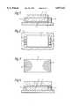
- FIG. 1is a schematic cross-section of a liquid crystal display apparatus in accordance with the present invention
- FIG. 2is a plan view of the liquid crystal display apparatus in FIG. 1;
- FIG. 3is a plan view of an attenuating member for use in the liquid crystal display apparatus in FIGS. 1 and 2;
- FIG. 4is a schematic cross-section of a different liquid crystal display apparatus in accordance with the invention.
- FIG. 5is a plan view of a different attenuating member
- FIG. 6is a plan view of a further attenuating member.
- FIG. 7is a plan view of another attenuating member.
- the apparatus shown in FIG. 1comprises a conventional liquid crystal display (LCD) 1 behind which is mounted in contiguous relationship a flat plate-like light guide 2 made, for example of acrylic.
- LCDliquid crystal display
- the front face of the light guide 2i.e. the face adjacent the LCD 1, may be roughened in known manner to promote the escape of light into the LCD.
- a number of light emitting diodes (LED's) 3are provided along opposing side faces of the light guide for injecting light into the light guide. As can be seen in FIG. 2, a row of three LEDs is used on each of the two opposite side faces. The two sets of three LEDs are present in a respective recess 4 at the sides of the light guide 2.
- a light attenuating member 5in this case a thin sheet of reflective material, e.g. white paper, on which is printed in black ink a pattern of dots 6 as shown in FIG. 3.
- the pattern of dotsincludes two half-elipse shapes 6 extending respectively from the edge of the attenuation sheet 5 adjacent the rows of LEDs 3.
- the half-ellipse shapes 6are each filled with a regular array of equally sized and equally spaced dots printed with a conventional black printing ink.
- the pattern of dotsmay, for example, be printed using a laser printer or a bubble jet printer. These two dot patterns reduce the overall level of reflection at the back face of the light guide at the two half-elliptical areas. This has the effect of attenuating the amount of light which escapes from the light guide 5 into the LCD 1 at the corresponding areas. Hence a more uniform illumination can be achieved over the whole area of the LCD 1.
- the pattern of dots described hereprovides remarkable results in a low-profile LCD apparatus. Moreover, it transpires that the dot pattern is not critical. Thus if the pattern varies slightly, either across the width of the half-elliptical areas, or from product to product; or if the dot pattern is imperfect, e.g. some of the dots may be inadvertently omitted or poorly defined; it would appear that these defects have virtually no appreciable effect on the performance of the attenuator and excellent uniformity of illumination is still achieved. On the other hand if it is desired to vary the degree of attenuation it will be evident that this can be done by varying the size and/or frequency of the dots, i.e. altering the proportion of black to white areas.
- the whole LCD apparatusmay be supported on a substrate such as a printed circuit board 7 in conventional manner.
- FIG. 4there is shown a modification of the LCD apparatus described above.
- the same reference numeralsare used to denote the corresponding parts as in the previous embodiment described with reference to FIGS. 1 to 3.
- the attenuating sheet 5is provided between the LCD 1 and the light guide 2.
- the sheet 5may be transparent (or translucent) and have a pattern of dots printed thereon as before.
- the dots themselvesmay either be reflective or absorbing, in either case they will help to prevent light escaping into the LCD at the patterned areas.
- the patterned areas on the attenuating membermay be the same as those described in the previous embodiment with reference to FIG. 3.
- the attenuating memberneed not be provided as a separate sheet but may be coated directly on the relevant surface of the light guide.
- the attenuating coatingwould be provided selectively on the light guide surface.
- the reflective coatingwould be provided on the back face of the light guide 2, and the pattern of dots would be provided by omitting or removing the coating to form the dots.
- the coatingwould be selectively provided (or retained) only at the areas corresponding to the dot patterns.
- the dot patterns provided on the attenuating meansmay have a graduated, rather than a uniform distribution, so as to attenuate the light less severely at greater distances from the light source.
- dot patterns 6'comprise a number of parallel bars extending transversely to the longitudial axis of the display. These bars provide progressively less attenuation the further they are away from the side edge of the attenuator 5'. This is achieved either by reducing the size or frequency of the dots from bar to bar.
- FIG. 6there is shown an attenuating member 50 for use where the illumination is provided by three LEDs 30 along one long side of the display and three further LEDs 30 along the opposite long side of the display.
- Each LED 30has a respective half-elliptical pattern 60 of dots on the attenuator 50 extending from the edge adjacent the respective LED 30 towards the longitudial axis of the attenuator.
- these dot patterns 60provide gradually less attenuation as the distance from the LED 30 increases. This is achieved either by reducing the size or frequency of the dots.
- FIG. 7there is a shown an attenuator 150 for use in an LCD apparatus where the LEDs are provided behind (rather than at the edge of) the light guide.
- the LEDsare provided behind (rather than at the edge of) the light guide.
- six LEDs 130are provided behind the LCD, and six circular dot patterns 160 are provided on the attenuator 150, the central point of each circular dot pattern being registered with a respective LED 130.
- each pattern of dots 160is graduated radially around the area of the LEDs 130, again to provide less attenuation as the distance from the LED 130 increases, and so provide uniform illumination over the whole LCD area.
Landscapes
- Physics & Mathematics (AREA)
- General Physics & Mathematics (AREA)
- Optics & Photonics (AREA)
- Nonlinear Science (AREA)
- Mathematical Physics (AREA)
- Chemical & Material Sciences (AREA)
- Crystallography & Structural Chemistry (AREA)
- Liquid Crystal (AREA)
- Planar Illumination Modules (AREA)
- Light Guides In General And Applications Therefor (AREA)
- Devices For Indicating Variable Information By Combining Individual Elements (AREA)
Abstract
Description
This is a continuation of application Ser. No. 08/062,933 filed on May 17, 1993, abandoned.
This invention relates to an illuminated liquid crystal display apparatus and specifically to a liquid crystal display (LCD) which is illuminated from behind.
It is common practice to use a light guide (or so-called "light pipe") behind an LCD to distribute light from one or more light sources, such as light emitting diodes (LED's). The light guide is generally in the form of a plate-like member. Particularly in the case of a low-profile assembly, the LEDs are provided, for example, in a recess, at the side faces of the light guide. Light enters the light guide through the side faces and is distributed through the light guide by internal reflection. The front face of the light guide may be "roughened" to make it lossy so that light escapes into the LCD. The light guide thus acts to distribute light over a wide area of the LCD.
However, when relatively few light sources are used, there is a tendency for the illumination to be uneven over the whole area of the LCD. Generally the light is more intense nearer to the LED's and less intense further away.
U.S. Pat. No. 4,975,808 discloses a liquid crystal display apparatus which aims to provide a more uniform distribution of light across a low-profile LCD. In this case the back face of the light pipe is selectively painted white. A pattern in the form of a border, half-sun and ovals around each lamp is left unpainted. The smooth unpainted surfaces of the light pipe internally reflect light that has an angle of incidence less than the critical angle. The white paint provides diffuse reflection, scattering the light. Some of this light escapes the light pipe and enters the LCD. The unpainted portion has the effect of dimming the so-called hot spots caused by the proximity of the light-sources, and increasing the brightness in the painted area. While this arrangement goes some way to improving uniformity of illumination, it still leaves room for improvement. Moreover, the use of painted and unpainted reflected areas provides only limited scope for varying the relative intensity in the dimmer areas insofar as the intensity is enhanced equally in all painted areas and there is little or no control over the degree of intensity enhancement in the painted areas.
According to the present invention there is provided an illuminated liquid crystal display apparatus, comprising a liquid crystal display, at least one light source, a light guide comprising a transparent plate-like member having front, back and side faces disposed behind the liquid crystal display for distributing light from the light source over an area of the liquid crystal display, and light-attenuating means disposed adjacent the light guide and including discrete areas substantially filled with a pattern of dots for reducing the intensity of light reaching portions of the liquid crystal display nearest to the light source.
A back-lit liquid crystal display (LCD) apparatus in accordance with the invention has the advantage that it is very simple and inexpensive to implement, it gives remarkably uniform back illumination, and it offers the potential of varying the level of attenuation at would-be hot spots by altering the density and/or distribution of the dot pattern.
It is noted here that in the present context the term "dot" is not restricted to a small circular area and the expression "pattern of dots" is intended to include any discontinuous pattern of recurring features such as dashes, ovals, stars, squares or other shapes.
The light-attenuating means may be a thin sheet provided against either the front or back face of the light guide. In the former case the sheet is translucent, and the dots are non-translucent (absorbing or reflective). In the latter case the sheet is reflective and the dots are non-reflective. Alternatively a reflective layer may be coated directly on the back face of the light guide and the spots are formed by selective removal or omission of the coating. On the other hand a pattern of light-blocking dots may be formed directly on the front face of the light guide.
In each of the four examples mentioned in the preceding paragraph the apparatus can be made very slim indeed. It will be clear that where the attenuating means is coated directly on the front or back face of the light guide that the additional space in the thickness direction is negligible. However, even when the attenuating member is formed as a sheet, the thickness of the sheet can be very small. For example the sheet may be a sheet of paper on which the pattern of dots is printed with conventional black ink.
In one example the pattern of dots is substantially uniform, i.e. all the dots have the same shape, size, and pitch. In another example the pattern of dots is graduated, i.e. the ratio of the black to white, or reflective area to non-reflective area, varies gradually so that the intensity of light reaching the LCD is reduced less as the distance from the light source increases.
Embodiments of the invention will now be described, by way of example, with reference to the accompanying drawings, in which:
FIG. 1 is a schematic cross-section of a liquid crystal display apparatus in accordance with the present invention;
FIG. 2 is a plan view of the liquid crystal display apparatus in FIG. 1;
FIG. 3 is a plan view of an attenuating member for use in the liquid crystal display apparatus in FIGS. 1 and 2;
FIG. 4 is a schematic cross-section of a different liquid crystal display apparatus in accordance with the invention;
FIG. 5 is a plan view of a different attenuating member;
FIG. 6 is a plan view of a further attenuating member; and
FIG. 7 is a plan view of another attenuating member.
The apparatus shown in FIG. 1 comprises a conventional liquid crystal display (LCD) 1 behind which is mounted in contiguous relationship a flat plate-like light guide 2 made, for example of acrylic.
The front face of thelight guide 2, i.e. the face adjacent theLCD 1, may be roughened in known manner to promote the escape of light into the LCD. A number of light emitting diodes (LED's) 3 are provided along opposing side faces of the light guide for injecting light into the light guide. As can be seen in FIG. 2, a row of three LEDs is used on each of the two opposite side faces. The two sets of three LEDs are present in a respective recess 4 at the sides of thelight guide 2.
Beneath thelight guide 2, and in contiguous relationship therewith, there is provided a light attenuatingmember 5, in this case a thin sheet of reflective material, e.g. white paper, on which is printed in black ink a pattern ofdots 6 as shown in FIG. 3. The pattern of dots includes two half-elipse shapes 6 extending respectively from the edge of theattenuation sheet 5 adjacent the rows ofLEDs 3.
The half-ellipse shapes 6 are each filled with a regular array of equally sized and equally spaced dots printed with a conventional black printing ink. The pattern of dots may, for example, be printed using a laser printer or a bubble jet printer. These two dot patterns reduce the overall level of reflection at the back face of the light guide at the two half-elliptical areas. This has the effect of attenuating the amount of light which escapes from thelight guide 5 into theLCD 1 at the corresponding areas. Hence a more uniform illumination can be achieved over the whole area of theLCD 1.
In practice the Applicant has found that the pattern of dots described here provides remarkable results in a low-profile LCD apparatus. Moreover, it transpires that the dot pattern is not critical. Thus if the pattern varies slightly, either across the width of the half-elliptical areas, or from product to product; or if the dot pattern is imperfect, e.g. some of the dots may be inadvertently omitted or poorly defined; it would appear that these defects have virtually no appreciable effect on the performance of the attenuator and excellent uniformity of illumination is still achieved. On the other hand if it is desired to vary the degree of attenuation it will be evident that this can be done by varying the size and/or frequency of the dots, i.e. altering the proportion of black to white areas.
The whole LCD apparatus may be supported on a substrate such as a printedcircuit board 7 in conventional manner.
In FIG. 4 there is shown a modification of the LCD apparatus described above. In FIG. 4 the same reference numerals are used to denote the corresponding parts as in the previous embodiment described with reference to FIGS. 1 to 3. In this case the attenuatingsheet 5 is provided between theLCD 1 and thelight guide 2. Thesheet 5 may be transparent (or translucent) and have a pattern of dots printed thereon as before. The dots themselves may either be reflective or absorbing, in either case they will help to prevent light escaping into the LCD at the patterned areas. The patterned areas on the attenuating member may be the same as those described in the previous embodiment with reference to FIG. 3.
It is noted here that the attenuating member need not be provided as a separate sheet but may be coated directly on the relevant surface of the light guide. Suitably the attenuating coating would be provided selectively on the light guide surface. Thus in the first embodiment the reflective coating would be provided on the back face of thelight guide 2, and the pattern of dots would be provided by omitting or removing the coating to form the dots. In the configuration shown in the second embodiment however the coating would be selectively provided (or retained) only at the areas corresponding to the dot patterns.
The dot patterns provided on the attenuating means may have a graduated, rather than a uniform distribution, so as to attenuate the light less severely at greater distances from the light source. Thus for example there is shown in FIG. 5 an alternative dot pattern which may be used for theattenuator 5 in a LCD apparatus which is side lit as in the previous embodiments. Here dot patterns 6' comprise a number of parallel bars extending transversely to the longitudial axis of the display. These bars provide progressively less attenuation the further they are away from the side edge of the attenuator 5'. This is achieved either by reducing the size or frequency of the dots from bar to bar.
In FIG. 6 there is shown an attenuating member 50 for use where the illumination is provided by three LEDs 30 along one long side of the display and three further LEDs 30 along the opposite long side of the display. Each LED 30 has a respective half-elliptical pattern 60 of dots on the attenuator 50 extending from the edge adjacent the respective LED 30 towards the longitudial axis of the attenuator. As can be seen from FIG. 6 these dot patterns 60 provide gradually less attenuation as the distance from the LED 30 increases. This is achieved either by reducing the size or frequency of the dots.
In FIG. 7 there is a shown an attenuator 150 for use in an LCD apparatus where the LEDs are provided behind (rather than at the edge of) the light guide. In this case, six LEDs 130 are provided behind the LCD, and six circular dot patterns 160 are provided on the attenuator 150, the central point of each circular dot pattern being registered with a respective LED 130. In this case each pattern of dots 160 is graduated radially around the area of the LEDs 130, again to provide less attenuation as the distance from the LED 130 increases, and so provide uniform illumination over the whole LCD area.
It will be evident in view of the foregoing description that various modifications may be made within the scope of the present invention. In particular different patterns of dots may be used on the attenuator in different circumstances. The overall shape of the dot pattern may be varied to suit particular needs, as too may the size and frequency of the dots making up the pattern. In the case of the graduated dot pattern, the graduation may be continuous rather than step-wise, in which case the distinct bands visible in FIGS. 5-7 would not be discernible. Finally, it is noted that light sources other than LEDs may be used for illuminating the LCD apparatus.
Claims (8)
1. An illuminated liquid crystal display apparatus, comprising:
a liquid crystal display,
a plurality of point light sources generally located behind the liquid crystal display,
a light guide comprising a transparent plate-like member having side faces disposed behind the liquid crystal display for distributing light from the light sources over an area of the liquid crystal display, and
light-attenuating means disposed adjacent the light guide and including a pattern of dots defining a distinct individual portion proximate each one of the point light sources and spaced from one another for reducing the intensity of light reaching portions of the liquid crystal display nearest to the individual point light sources.
2. An illuminated liquid crystal display apparatus as claimed in claim 1, wherein the light-attenuating means comprises a reflective sheet and the dots provided thereon are non-reflective.
3. An illuminated liquid crystal display apparatus as claimed in claim 1, wherein the light-attenuating means comprises a reflective layer coated on the light guide, and the dots provided therein are non-reflective.
4. An illuminated liquid crystal display apparatus as claimed in claim 1, wherein the light attenuating means comprises a translucent sheet and the dots provided thereon are non-translucent.
5. An illuminated liquid crystal display apparatus as claimed in claim 1 wherein the light attenuating means comprises a pattern of light-blocking dots.
6. An illuminated liquid crystal display apparatus as claimed in claim 1, wherein the pattern of dots is graduated whereby the intensity of light reaching the liquid crystal display is reduced less as the distance from the light source increases.
7. An illuminated crystal display apparatus as claimed in claim 6, wherein the plurality of light sources are disposed adjacent at least one of the side faces of the light guide, and the pattern of dots is graduated linearly.
8. An illuminated guide crystal display apparatus as claimed in claim 6, wherein the point light sources are provided behind the light guide, and the pattern of dots is graduated radially around the areas of the individual light sources.
Priority Applications (1)
| Application Number | Priority Date | Filing Date | Title |
|---|---|---|---|
| US08/330,099US5477422A (en) | 1992-05-22 | 1994-10-27 | Illuminated LCD apparatus |
Applications Claiming Priority (4)
| Application Number | Priority Date | Filing Date | Title |
|---|---|---|---|
| GB9211006 | 1992-05-22 | ||
| GB9211006AGB2267378B (en) | 1992-05-22 | 1992-05-22 | Illuminated LCD apparatus |
| US6293393A | 1993-05-17 | 1993-05-17 | |
| US08/330,099US5477422A (en) | 1992-05-22 | 1994-10-27 | Illuminated LCD apparatus |
Related Parent Applications (1)
| Application Number | Title | Priority Date | Filing Date |
|---|---|---|---|
| US6293393AContinuation | 1992-05-22 | 1993-05-17 |
Publications (1)
| Publication Number | Publication Date |
|---|---|
| US5477422Atrue US5477422A (en) | 1995-12-19 |
Family
ID=10715939
Family Applications (1)
| Application Number | Title | Priority Date | Filing Date |
|---|---|---|---|
| US08/330,099Expired - LifetimeUS5477422A (en) | 1992-05-22 | 1994-10-27 | Illuminated LCD apparatus |
Country Status (5)
| Country | Link |
|---|---|
| US (1) | US5477422A (en) |
| EP (1) | EP0571173B1 (en) |
| JP (1) | JP3305411B2 (en) |
| DE (1) | DE69325681T2 (en) |
| GB (1) | GB2267378B (en) |
Cited By (80)
| Publication number | Priority date | Publication date | Assignee | Title |
|---|---|---|---|---|
| US5796450A (en)* | 1994-12-16 | 1998-08-18 | Canon Kabushiki Kaisha | Illumination device and liquid crystal display apparatus including same |
| US5870156A (en)* | 1996-09-05 | 1999-02-09 | Northern Telecom Limited | Shadow mask for backlit LCD |
| FR2802009A1 (en)* | 1999-12-07 | 2001-06-08 | Thomson Csf Sextant | Liquid crystal display panel includes light emitting diode light box to illuminate display |
| US6275339B1 (en)* | 1998-03-25 | 2001-08-14 | CHAZALLET FRéDéRIC | Edge-lighted luminous device |
| EP1216481A1 (en)* | 2000-01-14 | 2002-06-26 | Robert Bosch Gmbh | Device for inputting and/or outputting information |
| US6467922B1 (en) | 1999-12-09 | 2002-10-22 | Gc Communication | Method and apparatus for laser machining light guides, light guides obtained thereby, and back-lit screens incorporating such light guides |
| US6504586B1 (en) | 1998-09-24 | 2003-01-07 | Samsung Electronics Co., Ltd. | Liquid crystal display modules and holding assemblies applied to the same |
| US20030067565A1 (en)* | 2001-10-05 | 2003-04-10 | Nobuyuki Yamamura | Liquid crystal display |
| US20040008507A1 (en)* | 2002-07-09 | 2004-01-15 | Lee Sang-Duk | Light guiding apparatus, backlight assembly and liquid crystal display device having the same |
| US20040017675A1 (en)* | 2002-07-26 | 2004-01-29 | Hannstar Display Corp. | Panel light source device and back light module for liquid crystal displaly device |
| US20040042194A1 (en)* | 2002-09-02 | 2004-03-04 | Hsieh Chih Chieh | Panel light source device and liquid crystal display device |
| US20040080926A1 (en)* | 2002-10-23 | 2004-04-29 | Hannstar Display Corp. | Polarized light source device and back light module for liquid crystal display |
| US6755534B2 (en) | 2001-08-24 | 2004-06-29 | Brookhaven Science Associates | Prismatic optical display |
| US20040141305A1 (en)* | 2002-12-27 | 2004-07-22 | Casio Computer Co., Ltd. | Surface-shaped light irradiation device |
| DE10308523A1 (en)* | 2003-02-26 | 2004-09-16 | Ralph Zernisch | Electrical lighting panel has a main panel with inset strip lights and outer cover of diffuser and shadow material |
| US20040252485A1 (en)* | 2003-03-28 | 2004-12-16 | Charles Leu | Diffusion board having different areas with different refractive indices |
| US20050002205A1 (en)* | 2003-07-02 | 2005-01-06 | Chuan-Pei Yu | Backlight module |
| WO2005001331A1 (en)* | 2003-06-27 | 2005-01-06 | Philips Intellectual Property & Standards Gmbh | Luminous body |
| US20050007516A1 (en)* | 2003-07-07 | 2005-01-13 | Lg.Philips Lcd Co., Ltd. | Liquid crystal display module and driving method thereof |
| US20060072300A1 (en)* | 2004-10-05 | 2006-04-06 | Alps Electric Co., Ltd. | Illumination device |
| US20060221268A1 (en)* | 2005-04-01 | 2006-10-05 | Hyung-Seok Ko | Display device |
| FR2884593A1 (en)* | 2005-04-19 | 2006-10-20 | Dit Guerlain Pierre Bouille | Luminous plate device e.g. light-box, for backlighting, has light emitting diodes integrated in luminous plate, and fresco, of patterns printed on acetate film, associated to luminous plate that is disposed against opaque panel |
| US20060256577A1 (en)* | 1999-02-23 | 2006-11-16 | Solid State Opto Limited | Light redirecting films and film systems |
| US20060285355A1 (en)* | 2004-09-15 | 2006-12-21 | James Robinson | Method and device to improve backlight uniformity |
| US7207699B2 (en)* | 2000-03-09 | 2007-04-24 | Siteco Beleuchtungstechnik Gmbh | System of light units |
| US20070133227A1 (en)* | 2005-12-12 | 2007-06-14 | Au Optronics Corporation | Backlight module |
| US20070165156A1 (en)* | 2004-01-08 | 2007-07-19 | Sharp Kabushiki Kaisha | Lighting device for display devices, liquid crystal display device, and light source lamp |
| US20080024696A1 (en)* | 2004-10-08 | 2008-01-31 | Sony Corporation | Light Source Device for Backlight, Backlight Device for Liquid Crystal Display Apparatus and Transmissive Liquid Crystal Display |
| US20080055928A1 (en)* | 2006-08-09 | 2008-03-06 | Sony Corporation | Backlight device, light source device, lens, electronic apparatus and light guide plate |
| GB2443111A (en)* | 2004-01-08 | 2008-04-23 | Sharp Kk | Partial reflection reduction from a curved lamp in an illumination device for display devices. |
| EP1930651A1 (en) | 2006-12-05 | 2008-06-11 | Stanley Electric Co., Ltd. | Light source device and vehicle lighting device |
| WO2008044170A3 (en)* | 2006-10-10 | 2008-06-12 | Koninkl Philips Electronics Nv | Thin illumination device, display device and luminary device |
| US20080252591A1 (en)* | 2005-11-14 | 2008-10-16 | Koninklijke Philips Electronics, N.V. | Distributing and Driving Light Sources of Backlights |
| US20080285268A1 (en)* | 2004-11-09 | 2008-11-20 | Takashi Oku | Backlight Device |
| US20080284942A1 (en)* | 2004-08-18 | 2008-11-20 | Kazutoshi Mahama | Backlight Device and Transmission Type Liquid Crystal Display Apparatus |
| US20080319715A1 (en)* | 2007-06-22 | 2008-12-25 | Samsung Electronics Co. Ltd. | Light guide plate, method of manufacturing the same, and liquid crystal display device including the same |
| US20090067194A1 (en)* | 2007-09-11 | 2009-03-12 | World Properties, Inc. | Light guide with imprinted phosphor |
| US20090161339A1 (en)* | 2007-12-19 | 2009-06-25 | David Gonzalez | Control of emitted light from luminaire |
| FR2928993A1 (en)* | 2008-03-20 | 2009-09-25 | Guillaume Boulais | LIGHTING MODULE, IN PARTICULAR RETRO-LIGHTING |
| US20100182785A1 (en)* | 2009-01-20 | 2010-07-22 | Touchsensor Technologies, Llc | User interface with means for light bleed mitigation |
| US20110286235A1 (en)* | 2010-05-18 | 2011-11-24 | Young Lighting Technology Corporation | Backlight module |
| CN1749828B (en)* | 2004-09-15 | 2012-02-15 | 捷讯研究有限公司 | Method and apparatus for compensating for non-uniform illumination from a light guide for a liquid crystal display |
| US20120048708A1 (en)* | 2010-08-25 | 2012-03-01 | Salter Stuart C | Light Bar Proximity Switch |
| EP2447767A1 (en)* | 2010-11-02 | 2012-05-02 | LG Innotek Co., Ltd. | Light emitting device, light emitting device package, and light unit |
| US8796575B2 (en) | 2012-10-31 | 2014-08-05 | Ford Global Technologies, Llc | Proximity switch assembly having ground layer |
| US8878438B2 (en) | 2011-11-04 | 2014-11-04 | Ford Global Technologies, Llc | Lamp and proximity switch assembly and method |
| US20140340920A1 (en)* | 2013-05-17 | 2014-11-20 | Lisa Dräxlmaier GmbH | Flat device for illuminating the interior of a vehicle |
| US8922340B2 (en) | 2012-09-11 | 2014-12-30 | Ford Global Technologies, Llc | Proximity switch based door latch release |
| US8928336B2 (en) | 2011-06-09 | 2015-01-06 | Ford Global Technologies, Llc | Proximity switch having sensitivity control and method therefor |
| US8933708B2 (en) | 2012-04-11 | 2015-01-13 | Ford Global Technologies, Llc | Proximity switch assembly and activation method with exploration mode |
| US8975903B2 (en) | 2011-06-09 | 2015-03-10 | Ford Global Technologies, Llc | Proximity switch having learned sensitivity and method therefor |
| US8981602B2 (en) | 2012-05-29 | 2015-03-17 | Ford Global Technologies, Llc | Proximity switch assembly having non-switch contact and method |
| US8994228B2 (en) | 2011-11-03 | 2015-03-31 | Ford Global Technologies, Llc | Proximity switch having wrong touch feedback |
| US9065447B2 (en) | 2012-04-11 | 2015-06-23 | Ford Global Technologies, Llc | Proximity switch assembly and method having adaptive time delay |
| US9136840B2 (en) | 2012-05-17 | 2015-09-15 | Ford Global Technologies, Llc | Proximity switch assembly having dynamic tuned threshold |
| US9143126B2 (en) | 2011-09-22 | 2015-09-22 | Ford Global Technologies, Llc | Proximity switch having lockout control for controlling movable panel |
| US9184745B2 (en) | 2012-04-11 | 2015-11-10 | Ford Global Technologies, Llc | Proximity switch assembly and method of sensing user input based on signal rate of change |
| US9197206B2 (en) | 2012-04-11 | 2015-11-24 | Ford Global Technologies, Llc | Proximity switch having differential contact surface |
| US9219472B2 (en) | 2012-04-11 | 2015-12-22 | Ford Global Technologies, Llc | Proximity switch assembly and activation method using rate monitoring |
| US9287864B2 (en) | 2012-04-11 | 2016-03-15 | Ford Global Technologies, Llc | Proximity switch assembly and calibration method therefor |
| US9311204B2 (en) | 2013-03-13 | 2016-04-12 | Ford Global Technologies, Llc | Proximity interface development system having replicator and method |
| US9337832B2 (en) | 2012-06-06 | 2016-05-10 | Ford Global Technologies, Llc | Proximity switch and method of adjusting sensitivity therefor |
| US9520875B2 (en) | 2012-04-11 | 2016-12-13 | Ford Global Technologies, Llc | Pliable proximity switch assembly and activation method |
| US9531379B2 (en) | 2012-04-11 | 2016-12-27 | Ford Global Technologies, Llc | Proximity switch assembly having groove between adjacent proximity sensors |
| US9548733B2 (en) | 2015-05-20 | 2017-01-17 | Ford Global Technologies, Llc | Proximity sensor assembly having interleaved electrode configuration |
| US9559688B2 (en) | 2012-04-11 | 2017-01-31 | Ford Global Technologies, Llc | Proximity switch assembly having pliable surface and depression |
| US9568527B2 (en) | 2012-04-11 | 2017-02-14 | Ford Global Technologies, Llc | Proximity switch assembly and activation method having virtual button mode |
| US9625633B2 (en) | 2003-06-23 | 2017-04-18 | Rambus Delaware Llc | Light emitting panel assemblies |
| US9641172B2 (en) | 2012-06-27 | 2017-05-02 | Ford Global Technologies, Llc | Proximity switch assembly having varying size electrode fingers |
| US9654103B2 (en) | 2015-03-18 | 2017-05-16 | Ford Global Technologies, Llc | Proximity switch assembly having haptic feedback and method |
| US9660644B2 (en) | 2012-04-11 | 2017-05-23 | Ford Global Technologies, Llc | Proximity switch assembly and activation method |
| US9659489B2 (en) | 2012-02-22 | 2017-05-23 | Denso Corporation | Display apparatus |
| CN106997065A (en)* | 2017-05-18 | 2017-08-01 | 常州丰盛光电科技股份有限公司 | Optical enhancement type ink-jet diffuser plate |
| US9831870B2 (en) | 2012-04-11 | 2017-11-28 | Ford Global Technologies, Llc | Proximity switch assembly and method of tuning same |
| US9944237B2 (en) | 2012-04-11 | 2018-04-17 | Ford Global Technologies, Llc | Proximity switch assembly with signal drift rejection and method |
| US10004286B2 (en) | 2011-08-08 | 2018-06-26 | Ford Global Technologies, Llc | Glove having conductive ink and method of interacting with proximity sensor |
| US10038443B2 (en) | 2014-10-20 | 2018-07-31 | Ford Global Technologies, Llc | Directional proximity switch assembly |
| US10112556B2 (en) | 2011-11-03 | 2018-10-30 | Ford Global Technologies, Llc | Proximity switch having wrong touch adaptive learning and method |
| EP3479168A4 (en)* | 2016-06-29 | 2020-02-19 | Boe Technology Group Co. Ltd. | VIEWING ANGLE CONTROL DEVICE AND DISPLAY DEVICE |
| CN113994138A (en)* | 2019-04-24 | 2022-01-28 | 豪倍公司 | Edge-lit light kit for ceiling fans |
Families Citing this family (25)
| Publication number | Priority date | Publication date | Assignee | Title |
|---|---|---|---|---|
| GB9317086D0 (en)* | 1993-08-17 | 1993-09-29 | Robertson Stowe Ltd | Planar illumination apparatus |
| EP0660293A3 (en)* | 1993-12-23 | 1995-10-25 | Osa Elektronik Gmbh | Lighting or display device with light coupling in a waveguide. |
| DE69522183T2 (en)* | 1994-12-16 | 2002-04-25 | Canon Kk | Lighting device and liquid crystal display containing the same |
| GB2296362B (en) | 1994-12-23 | 1999-03-03 | Nokia Mobile Phones Ltd | Illuminated LCD apparatus and method of manufacture |
| FR2737162B1 (en)* | 1995-07-27 | 1997-10-17 | Magneti Marelli France | DISPLAY DEVICE, ESPECIALLY FOR DASHBOARDS |
| EP0781959A1 (en)* | 1995-12-28 | 1997-07-02 | AT&T Corp. | Transparent display with diffuser-backed microtextured illuminating device and method of manufacture therefor |
| US5896229A (en)* | 1997-02-20 | 1999-04-20 | Ericsson Inc. | Discretely applied diffusor structures on lightguides |
| SG67385A1 (en)* | 1997-04-14 | 2001-07-24 | Hewlett Packard Co | A method and device for conducting and substantially evenly dispersing light from a light source |
| JP2001043720A (en)* | 1999-07-28 | 2001-02-16 | Sanyo Electric Co Ltd | Surface light source device and display device |
| DE10011160B4 (en)* | 2000-03-12 | 2012-03-08 | Insta Elektro Gmbh | Illuminated electronic operating unit for building system technology |
| JP4623336B2 (en)* | 2000-05-02 | 2011-02-02 | ソニー株式会社 | Display device and dimming pattern generation method |
| JP2002042529A (en)* | 2000-07-24 | 2002-02-08 | Sanyo Electric Co Ltd | Surface lighting device |
| JP4711541B2 (en)* | 2001-05-18 | 2011-06-29 | 京セラ株式会社 | Lighting panel, liquid crystal display device and portable terminal or display device |
| FR2842340B1 (en)* | 2002-07-11 | 2005-03-04 | Colas Sa | LUMINOUS PANEL WITH LIGHTING BY WAFER |
| US20040056989A1 (en)* | 2002-09-24 | 2004-03-25 | Betz Alexander C. | Parameter floodlit LCD |
| US6974229B2 (en) | 2003-05-21 | 2005-12-13 | Lumileds Lighting U.S., Llc | Devices for creating brightness profiles |
| EP1566686A1 (en)* | 2004-02-20 | 2005-08-24 | ETA SA Manufacture Horlogère Suisse | Backlight device for display element |
| DK1650730T3 (en)* | 2004-10-25 | 2010-05-03 | Barco Nv | Optical correction for high uniformity light panels |
| US7815355B2 (en) | 2005-08-27 | 2010-10-19 | 3M Innovative Properties Company | Direct-lit backlight having light recycling cavity with concave transflector |
| US7537374B2 (en) | 2005-08-27 | 2009-05-26 | 3M Innovative Properties Company | Edge-lit backlight having light recycling cavity with concave transflector |
| KR101298786B1 (en) | 2005-08-27 | 2013-08-22 | 쓰리엠 이노베이티브 프로퍼티즈 컴파니 | Illumination assembly and system |
| CN103017088A (en)* | 2005-10-17 | 2013-04-03 | I2Ic公司 | Apparatus and method for providing a light source in the form of a surface |
| JP5339773B2 (en)* | 2008-05-08 | 2013-11-13 | 株式会社ジャパンディスプレイ | Liquid crystal display |
| WO2012165248A1 (en)* | 2011-05-30 | 2012-12-06 | シャープ株式会社 | Illuminating apparatus, display apparatus, and television receiver |
| CN103175034A (en)* | 2013-03-26 | 2013-06-26 | 南京中电熊猫液晶显示科技有限公司 | Light-emitting diode (LED) backlight module |
Citations (16)
| Publication number | Priority date | Publication date | Assignee | Title |
|---|---|---|---|---|
| DE2723483A1 (en)* | 1976-05-20 | 1977-11-24 | Ebauches Sa | Passive electrooptical display element - uses liq. crystal display operating with external light and light from internal source |
| US4206501A (en)* | 1978-06-12 | 1980-06-03 | Motorola, Inc. | Apparatus and methods for back illuminating a display surface |
| US4267489A (en)* | 1978-12-01 | 1981-05-12 | Ohno Research And Development Laboratories Company Limited | Thin schaukasten |
| GB2136186A (en)* | 1983-01-22 | 1984-09-12 | Borg Instr Gmbh | Illumination equipment for a transmissively-operable passive display |
| US4502761A (en)* | 1981-03-13 | 1985-03-05 | Robert Bosch Gmbh | Gradient-free illumination of passive readout display devices |
| EP0212415A1 (en)* | 1985-08-09 | 1987-03-04 | Hitachi, Ltd. | Liquid crystal display device |
| US4673254A (en)* | 1985-07-30 | 1987-06-16 | Tokyo Keiki Co., Ltd. | Back-reflection type light diffusing apparatus |
| US4729068A (en)* | 1986-10-01 | 1988-03-01 | Mitsubishi Rayon Company Ltd. | Light diffusing device |
| JPS63309918A (en)* | 1988-04-25 | 1988-12-19 | Tatsuji Mizobe | Back light device |
| US4803399A (en)* | 1985-08-14 | 1989-02-07 | Hitachi, Ltd. | Fluorescent lamp arrangement for uniformly illuminating a display panel |
| US4975808A (en)* | 1989-10-02 | 1990-12-04 | Motorola, Inc. | Backlighting apparatus |
| JPH039306A (en)* | 1989-06-07 | 1991-01-17 | Mitsubishi Petrochem Co Ltd | Backlight device |
| US4998804A (en)* | 1988-08-29 | 1991-03-12 | Sharp Kabushiki Kaisha | Transmissive liquid crystal display device |
| US5057974A (en)* | 1990-06-22 | 1991-10-15 | Tatsuji Mizobe | System for uniformly illuminating liquid crystal display board from rear side |
| EP0462361A1 (en)* | 1990-06-19 | 1991-12-27 | Enplas Corporation | Surface light source device |
| WO1992004400A1 (en)* | 1990-09-04 | 1992-03-19 | Ohno Research And Development Laboratories Co., Ltd. | Plastic optical member having light diffusing layer on surface, and light quantity control member |
- 1992
- 1992-05-22GBGB9211006Apatent/GB2267378B/ennot_activeExpired - Fee Related
- 1993
- 1993-05-18EPEP93303818Apatent/EP0571173B1/ennot_activeExpired - Lifetime
- 1993-05-18DEDE69325681Tpatent/DE69325681T2/ennot_activeExpired - Lifetime
- 1993-05-21JPJP11884493Apatent/JP3305411B2/ennot_activeExpired - Fee Related
- 1994
- 1994-10-27USUS08/330,099patent/US5477422A/ennot_activeExpired - Lifetime
Patent Citations (18)
| Publication number | Priority date | Publication date | Assignee | Title |
|---|---|---|---|---|
| DE2723483A1 (en)* | 1976-05-20 | 1977-11-24 | Ebauches Sa | Passive electrooptical display element - uses liq. crystal display operating with external light and light from internal source |
| US4206501A (en)* | 1978-06-12 | 1980-06-03 | Motorola, Inc. | Apparatus and methods for back illuminating a display surface |
| US4267489A (en)* | 1978-12-01 | 1981-05-12 | Ohno Research And Development Laboratories Company Limited | Thin schaukasten |
| US4502761A (en)* | 1981-03-13 | 1985-03-05 | Robert Bosch Gmbh | Gradient-free illumination of passive readout display devices |
| GB2136186A (en)* | 1983-01-22 | 1984-09-12 | Borg Instr Gmbh | Illumination equipment for a transmissively-operable passive display |
| US4673254A (en)* | 1985-07-30 | 1987-06-16 | Tokyo Keiki Co., Ltd. | Back-reflection type light diffusing apparatus |
| EP0212415A1 (en)* | 1985-08-09 | 1987-03-04 | Hitachi, Ltd. | Liquid crystal display device |
| US4803399A (en)* | 1985-08-14 | 1989-02-07 | Hitachi, Ltd. | Fluorescent lamp arrangement for uniformly illuminating a display panel |
| GB2196100A (en)* | 1986-10-01 | 1988-04-20 | Mitsubishi Rayon Co | Light diffusing device |
| US4729068A (en)* | 1986-10-01 | 1988-03-01 | Mitsubishi Rayon Company Ltd. | Light diffusing device |
| JPS63309918A (en)* | 1988-04-25 | 1988-12-19 | Tatsuji Mizobe | Back light device |
| US4998804A (en)* | 1988-08-29 | 1991-03-12 | Sharp Kabushiki Kaisha | Transmissive liquid crystal display device |
| JPH039306A (en)* | 1989-06-07 | 1991-01-17 | Mitsubishi Petrochem Co Ltd | Backlight device |
| US4975808A (en)* | 1989-10-02 | 1990-12-04 | Motorola, Inc. | Backlighting apparatus |
| EP0462361A1 (en)* | 1990-06-19 | 1991-12-27 | Enplas Corporation | Surface light source device |
| US5057974A (en)* | 1990-06-22 | 1991-10-15 | Tatsuji Mizobe | System for uniformly illuminating liquid crystal display board from rear side |
| WO1992004400A1 (en)* | 1990-09-04 | 1992-03-19 | Ohno Research And Development Laboratories Co., Ltd. | Plastic optical member having light diffusing layer on surface, and light quantity control member |
| EP0503071A1 (en)* | 1990-09-04 | 1992-09-16 | Ohno Research And Development Laboratories Co., Ltd. | Plastic optical member having light diffusing layer on surface, and light quantity control member |
Non-Patent Citations (3)
| Title |
|---|
| Patent Abstracts of Japan, vol. 13, No. 146 (P854) (3494) & JP63 309,918, Dec. 19, 1988, 1 page.* |
| Patent Abstracts of Japan, vol. 15, No. 119 (P 1183) & JP03 009306, Mar. 22, 1991, 1 page.* |
| Patent Abstracts of Japan, vol. 15, No. 119 (P-1183) & JP03-009306, Mar. 22, 1991, 1 page. |
Cited By (149)
| Publication number | Priority date | Publication date | Assignee | Title |
|---|---|---|---|---|
| US5796450A (en)* | 1994-12-16 | 1998-08-18 | Canon Kabushiki Kaisha | Illumination device and liquid crystal display apparatus including same |
| US5870156A (en)* | 1996-09-05 | 1999-02-09 | Northern Telecom Limited | Shadow mask for backlit LCD |
| US6275339B1 (en)* | 1998-03-25 | 2001-08-14 | CHAZALLET FRéDéRIC | Edge-lighted luminous device |
| US6504586B1 (en) | 1998-09-24 | 2003-01-07 | Samsung Electronics Co., Ltd. | Liquid crystal display modules and holding assemblies applied to the same |
| US7810982B2 (en) | 1999-02-23 | 2010-10-12 | Rambus International Ltd. | Edge-lit optical system having optical elements on two surfaces |
| US7364342B2 (en)* | 1999-02-23 | 2008-04-29 | Solid State Opto Limited | Light redirecting films pattern of variable optical elements |
| US8092068B2 (en) | 1999-02-23 | 2012-01-10 | Rambus International Ltd. | Light redirecting films and film systems |
| US20060256577A1 (en)* | 1999-02-23 | 2006-11-16 | Solid State Opto Limited | Light redirecting films and film systems |
| US7914196B2 (en) | 1999-02-23 | 2011-03-29 | Rambus International Ltd. | Light redirecting film systems having pattern of variable optical elements |
| US8845176B2 (en) | 1999-02-23 | 2014-09-30 | Rambus Delaware Llc | Light redirecting films with non-prismatic optical elements |
| US20110058390A1 (en)* | 1999-02-23 | 2011-03-10 | Parker Jeffery R | Light redirecting films and film systems |
| US20090135626A1 (en)* | 1999-02-23 | 2009-05-28 | Parker Jeffery R | Light redirecting films and film systems |
| US20080239755A1 (en)* | 1999-02-23 | 2008-10-02 | Parker Jeffery R | Light redirecting films and film systems |
| US20090034293A1 (en)* | 1999-02-23 | 2009-02-05 | Parker Jeffery R | Light redirecting films and film systems |
| US20090141517A1 (en)* | 1999-02-23 | 2009-06-04 | Parker Jeffery R | Light redirecting films and film systems |
| FR2802009A1 (en)* | 1999-12-07 | 2001-06-08 | Thomson Csf Sextant | Liquid crystal display panel includes light emitting diode light box to illuminate display |
| US6467922B1 (en) | 1999-12-09 | 2002-10-22 | Gc Communication | Method and apparatus for laser machining light guides, light guides obtained thereby, and back-lit screens incorporating such light guides |
| EP1216481A1 (en)* | 2000-01-14 | 2002-06-26 | Robert Bosch Gmbh | Device for inputting and/or outputting information |
| US7207699B2 (en)* | 2000-03-09 | 2007-04-24 | Siteco Beleuchtungstechnik Gmbh | System of light units |
| US6755534B2 (en) | 2001-08-24 | 2004-06-29 | Brookhaven Science Associates | Prismatic optical display |
| US20030067565A1 (en)* | 2001-10-05 | 2003-04-10 | Nobuyuki Yamamura | Liquid crystal display |
| US7349041B2 (en)* | 2001-10-05 | 2008-03-25 | Samsung Electronics Co., Ltd. | Liquid crystal display with light guiding plate removed from LCD panel and polarizing plate inside LCD panel |
| US7133092B2 (en)* | 2002-07-09 | 2006-11-07 | Samsung Electronics Co., Ltd. | Light guiding apparatus, backlight assembly and liquid crystal display device having the same and with integral diffuser |
| US20040008507A1 (en)* | 2002-07-09 | 2004-01-15 | Lee Sang-Duk | Light guiding apparatus, backlight assembly and liquid crystal display device having the same |
| US7580091B2 (en) | 2002-07-09 | 2009-08-25 | Samsung Electronics Co., Ltd. | Light guiding apparatus, backlight assembly and liquid crystal display device having the same |
| CN100397179C (en)* | 2002-07-09 | 2008-06-25 | 三星电子株式会社 | Light guide device, backlight assembly and liquid crystal display device |
| US20070127260A1 (en)* | 2002-07-09 | 2007-06-07 | Samsung Electronics Co., Ltd | Light guiding apparatus, backlight assembly and liquid crystal display device having the same |
| US20040017675A1 (en)* | 2002-07-26 | 2004-01-29 | Hannstar Display Corp. | Panel light source device and back light module for liquid crystal displaly device |
| US6893136B2 (en) | 2002-07-26 | 2005-05-17 | Hannstar Display Corp. | Panel light source device and back light module for liquid crystal display device |
| US20040042194A1 (en)* | 2002-09-02 | 2004-03-04 | Hsieh Chih Chieh | Panel light source device and liquid crystal display device |
| US6874900B2 (en) | 2002-09-02 | 2005-04-05 | Hannstar Display Corp. | Panel light source device and liquid crystal display device |
| US20060262515A1 (en)* | 2002-10-23 | 2006-11-23 | Hannstar Display Corp. | Polarized light source device and back light module for liquid crystal display |
| US7325961B2 (en) | 2002-10-23 | 2008-02-05 | Hannstar Display Corp. | Polarized light source device and back light module for liquid crystal display |
| US20040080926A1 (en)* | 2002-10-23 | 2004-04-29 | Hannstar Display Corp. | Polarized light source device and back light module for liquid crystal display |
| US7264390B2 (en) | 2002-10-23 | 2007-09-04 | Hannstar Display Corp. | Polarized light source device and back light module for liquid crystal display |
| US7083317B2 (en)* | 2002-12-27 | 2006-08-01 | Casio Computer Co., Ltd. | Surface-shaped light irradiation device |
| US20040141305A1 (en)* | 2002-12-27 | 2004-07-22 | Casio Computer Co., Ltd. | Surface-shaped light irradiation device |
| DE10308523A1 (en)* | 2003-02-26 | 2004-09-16 | Ralph Zernisch | Electrical lighting panel has a main panel with inset strip lights and outer cover of diffuser and shadow material |
| US20040252485A1 (en)* | 2003-03-28 | 2004-12-16 | Charles Leu | Diffusion board having different areas with different refractive indices |
| US9625633B2 (en) | 2003-06-23 | 2017-04-18 | Rambus Delaware Llc | Light emitting panel assemblies |
| US9983340B2 (en) | 2003-06-23 | 2018-05-29 | Rambus Delaware Llc | Light emitting panel assemblies |
| CN100526706C (en)* | 2003-06-27 | 2009-08-12 | 皇家飞利浦电子股份有限公司 | Luminous body |
| US8038308B2 (en) | 2003-06-27 | 2011-10-18 | Koninklijke Philips Electronics N.V. | Luminous body |
| JP2007516561A (en)* | 2003-06-27 | 2007-06-21 | コーニンクレッカ フィリップス エレクトロニクス エヌ ヴィ | Luminous body |
| WO2005001331A1 (en)* | 2003-06-27 | 2005-01-06 | Philips Intellectual Property & Standards Gmbh | Luminous body |
| US20080225509A1 (en)* | 2003-06-27 | 2008-09-18 | Horst Greiner | Luminous Body |
| US7121692B2 (en)* | 2003-07-02 | 2006-10-17 | Au Optronics Corp. | Backlight module |
| US20050002205A1 (en)* | 2003-07-02 | 2005-01-06 | Chuan-Pei Yu | Backlight module |
| US20050007516A1 (en)* | 2003-07-07 | 2005-01-13 | Lg.Philips Lcd Co., Ltd. | Liquid crystal display module and driving method thereof |
| US7538832B2 (en)* | 2003-07-07 | 2009-05-26 | Lg Display Co., Ltd. | Method and module for illuminating a liquid crystal display panel |
| GB2443111B (en)* | 2004-01-08 | 2008-07-23 | Sharp Kk | Partial reflection reduction from a curved lamp in an illumination device for display devices. |
| US20120243209A1 (en)* | 2004-01-08 | 2012-09-27 | Sharp Kabushiki Kaisha | Lighting device for display devices, liquid crystal display device, and light source lamp |
| US20100085736A1 (en)* | 2004-01-08 | 2010-04-08 | Sharp Kabushiki Kaisha | Lighting device for display devices, liquid crystal display device, and light source lamp |
| US7651233B2 (en) | 2004-01-08 | 2010-01-26 | Sharp Kabushiki Kaisha | Lighting device for display devices, liquid crystal display device, and light source lamp |
| GB2443111A (en)* | 2004-01-08 | 2008-04-23 | Sharp Kk | Partial reflection reduction from a curved lamp in an illumination device for display devices. |
| US8382307B2 (en)* | 2004-01-08 | 2013-02-26 | Sharp Kabushiki Kaisha | Lighting device for display devices, liquid crystal display device, and light source lamp |
| US8066395B2 (en)* | 2004-01-08 | 2011-11-29 | Sharp Kabushiki Kaisha | Lighting device for display devices, liquid crystal display device, and light source lamp |
| US20070165156A1 (en)* | 2004-01-08 | 2007-07-19 | Sharp Kabushiki Kaisha | Lighting device for display devices, liquid crystal display device, and light source lamp |
| US7667787B2 (en)* | 2004-08-18 | 2010-02-23 | Sony Corporation | Backlight device and transmission type liquid crystal display apparatus |
| US20080284942A1 (en)* | 2004-08-18 | 2008-11-20 | Kazutoshi Mahama | Backlight Device and Transmission Type Liquid Crystal Display Apparatus |
| US20100149205A1 (en)* | 2004-09-15 | 2010-06-17 | Research In Motion Limited | Method and device to improve backlight uniformity |
| CN1749828B (en)* | 2004-09-15 | 2012-02-15 | 捷讯研究有限公司 | Method and apparatus for compensating for non-uniform illumination from a light guide for a liquid crystal display |
| US20070291507A1 (en)* | 2004-09-15 | 2007-12-20 | Research In Motion Limited | Method and device to improve backlight uniformity |
| US20090010595A1 (en)* | 2004-09-15 | 2009-01-08 | Research In Motion Limited | Method and device to improve backlight uniformity |
| US7978942B2 (en) | 2004-09-15 | 2011-07-12 | Research In Motion Limited | Method and device to improve backlight uniformity |
| US7415176B2 (en) | 2004-09-15 | 2008-08-19 | Research In Motion Limited | Method and device to improve backlight uniformity |
| CN102537851A (en)* | 2004-09-15 | 2012-07-04 | 捷讯研究有限公司 | A method and device to improve backlight uniformity |
| US7445367B2 (en)* | 2004-09-15 | 2008-11-04 | Research In Motion Limited | Method and device to improve backlight uniformity |
| US7646448B2 (en) | 2004-09-15 | 2010-01-12 | Research In Motion Limited | Method and device to improve backlight uniformity |
| US20060285355A1 (en)* | 2004-09-15 | 2006-12-21 | James Robinson | Method and device to improve backlight uniformity |
| CN102537851B (en)* | 2004-09-15 | 2015-10-07 | 黑莓有限公司 | Improve the method and apparatus of backlight uniformity |
| EP1646062A1 (en)* | 2004-10-05 | 2006-04-12 | Alps Electric Co., Ltd. | lllumination device |
| US20060072300A1 (en)* | 2004-10-05 | 2006-04-06 | Alps Electric Co., Ltd. | Illumination device |
| US20080024696A1 (en)* | 2004-10-08 | 2008-01-31 | Sony Corporation | Light Source Device for Backlight, Backlight Device for Liquid Crystal Display Apparatus and Transmissive Liquid Crystal Display |
| US20080285268A1 (en)* | 2004-11-09 | 2008-11-20 | Takashi Oku | Backlight Device |
| US7946723B2 (en)* | 2004-11-09 | 2011-05-24 | Sony Corporation | Backlight device |
| US7515220B2 (en)* | 2005-04-01 | 2009-04-07 | Samsung Electronics Co., Ltd. | Display device |
| US20060221268A1 (en)* | 2005-04-01 | 2006-10-05 | Hyung-Seok Ko | Display device |
| FR2884593A1 (en)* | 2005-04-19 | 2006-10-20 | Dit Guerlain Pierre Bouille | Luminous plate device e.g. light-box, for backlighting, has light emitting diodes integrated in luminous plate, and fresco, of patterns printed on acetate film, associated to luminous plate that is disposed against opaque panel |
| US20080252591A1 (en)* | 2005-11-14 | 2008-10-16 | Koninklijke Philips Electronics, N.V. | Distributing and Driving Light Sources of Backlights |
| US20070133227A1 (en)* | 2005-12-12 | 2007-06-14 | Au Optronics Corporation | Backlight module |
| US8002453B2 (en)* | 2005-12-12 | 2011-08-23 | Au Optronics Corporation | Light-emitting diode backlight module and liquid crystal display using the same |
| US8272771B2 (en) | 2006-08-09 | 2012-09-25 | Sony Corporation | Backlight device, light source device, lens, electronic apparatus and light guide plate |
| US9574736B2 (en) | 2006-08-09 | 2017-02-21 | Sony Corporation | Backlight device, light source device, lens, electronic apparatus and light guide plate |
| US8690411B2 (en) | 2006-08-09 | 2014-04-08 | Sony Corporation | Backlight device, light source device, lens, electronic apparatus and light guide plate |
| US20080055928A1 (en)* | 2006-08-09 | 2008-03-06 | Sony Corporation | Backlight device, light source device, lens, electronic apparatus and light guide plate |
| US8251529B2 (en) | 2006-10-10 | 2012-08-28 | Koninklijke Philips Electronics N.V. | Thin illumination device, display device and luminary device |
| WO2008044170A3 (en)* | 2006-10-10 | 2008-06-12 | Koninkl Philips Electronics Nv | Thin illumination device, display device and luminary device |
| CN101523109B (en)* | 2006-10-10 | 2013-08-21 | 皇家飞利浦电子股份有限公司 | Thin lighting, display and light emitter devices |
| US20100033954A1 (en)* | 2006-10-10 | 2010-02-11 | Koninklijke Philips Electronics N.V. | Thin illumination device, display device and luminary device |
| EP1930651A1 (en) | 2006-12-05 | 2008-06-11 | Stanley Electric Co., Ltd. | Light source device and vehicle lighting device |
| US20080273351A1 (en)* | 2006-12-05 | 2008-11-06 | Shuichi Ajiki | Light Source Device and Vehicle Lighting Device |
| US7686489B2 (en) | 2006-12-05 | 2010-03-30 | Stanley Electric Co., Ltd. | Light source device and vehicle lighting device |
| US8684586B2 (en) | 2007-06-22 | 2014-04-01 | Samsung Display Co., Ltd. | Light guide plate, method of manufacturing the same, and liquid crystal display device including the same |
| US8540412B2 (en) | 2007-06-22 | 2013-09-24 | Samsung Display Co., Ltd. | Light guide plate, method of manufacturing the same, and liquid crystal display device including the same |
| US20080319715A1 (en)* | 2007-06-22 | 2008-12-25 | Samsung Electronics Co. Ltd. | Light guide plate, method of manufacturing the same, and liquid crystal display device including the same |
| US20100277951A1 (en)* | 2007-06-22 | 2010-11-04 | Samsung Electronics Co. Ltd. | Light guide plate, method of manufacturing the same, and liquid crystal display device including the same |
| US20090067194A1 (en)* | 2007-09-11 | 2009-03-12 | World Properties, Inc. | Light guide with imprinted phosphor |
| US8162497B2 (en)* | 2007-12-19 | 2012-04-24 | David Gonzalez | Control of emitted light from luminaire |
| US20090161339A1 (en)* | 2007-12-19 | 2009-06-25 | David Gonzalez | Control of emitted light from luminaire |
| FR2928993A1 (en)* | 2008-03-20 | 2009-09-25 | Guillaume Boulais | LIGHTING MODULE, IN PARTICULAR RETRO-LIGHTING |
| US20110013381A1 (en)* | 2008-03-20 | 2011-01-20 | Guillaume Boulais | Lighting module, in particular for back-lighting |
| US20100182785A1 (en)* | 2009-01-20 | 2010-07-22 | Touchsensor Technologies, Llc | User interface with means for light bleed mitigation |
| US8382357B2 (en)* | 2009-01-20 | 2013-02-26 | Touchsensor Technologies, Llc | User interface with means for light bleed mitigation |
| US8708540B2 (en)* | 2010-05-18 | 2014-04-29 | Young Lighting Technology Inc. | Backlight module with heat dissipation structure |
| US20110286235A1 (en)* | 2010-05-18 | 2011-11-24 | Young Lighting Technology Corporation | Backlight module |
| US20120048708A1 (en)* | 2010-08-25 | 2012-03-01 | Salter Stuart C | Light Bar Proximity Switch |
| US8454181B2 (en)* | 2010-08-25 | 2013-06-04 | Ford Global Technologies, Llc | Light bar proximity switch |
| US8814377B2 (en) | 2010-11-02 | 2014-08-26 | Lg Innotek Co., Ltd. | Backlight unit and display apparatus using the same |
| EP2447767A1 (en)* | 2010-11-02 | 2012-05-02 | LG Innotek Co., Ltd. | Light emitting device, light emitting device package, and light unit |
| US8928336B2 (en) | 2011-06-09 | 2015-01-06 | Ford Global Technologies, Llc | Proximity switch having sensitivity control and method therefor |
| US8975903B2 (en) | 2011-06-09 | 2015-03-10 | Ford Global Technologies, Llc | Proximity switch having learned sensitivity and method therefor |
| US10595574B2 (en) | 2011-08-08 | 2020-03-24 | Ford Global Technologies, Llc | Method of interacting with proximity sensor with a glove |
| US10004286B2 (en) | 2011-08-08 | 2018-06-26 | Ford Global Technologies, Llc | Glove having conductive ink and method of interacting with proximity sensor |
| US9143126B2 (en) | 2011-09-22 | 2015-09-22 | Ford Global Technologies, Llc | Proximity switch having lockout control for controlling movable panel |
| US10501027B2 (en) | 2011-11-03 | 2019-12-10 | Ford Global Technologies, Llc | Proximity switch having wrong touch adaptive learning and method |
| US8994228B2 (en) | 2011-11-03 | 2015-03-31 | Ford Global Technologies, Llc | Proximity switch having wrong touch feedback |
| US10112556B2 (en) | 2011-11-03 | 2018-10-30 | Ford Global Technologies, Llc | Proximity switch having wrong touch adaptive learning and method |
| US8878438B2 (en) | 2011-11-04 | 2014-11-04 | Ford Global Technologies, Llc | Lamp and proximity switch assembly and method |
| US9659489B2 (en) | 2012-02-22 | 2017-05-23 | Denso Corporation | Display apparatus |
| US9559688B2 (en) | 2012-04-11 | 2017-01-31 | Ford Global Technologies, Llc | Proximity switch assembly having pliable surface and depression |
| US9197206B2 (en) | 2012-04-11 | 2015-11-24 | Ford Global Technologies, Llc | Proximity switch having differential contact surface |
| US9287864B2 (en) | 2012-04-11 | 2016-03-15 | Ford Global Technologies, Llc | Proximity switch assembly and calibration method therefor |
| US9944237B2 (en) | 2012-04-11 | 2018-04-17 | Ford Global Technologies, Llc | Proximity switch assembly with signal drift rejection and method |
| US9831870B2 (en) | 2012-04-11 | 2017-11-28 | Ford Global Technologies, Llc | Proximity switch assembly and method of tuning same |
| US9065447B2 (en) | 2012-04-11 | 2015-06-23 | Ford Global Technologies, Llc | Proximity switch assembly and method having adaptive time delay |
| US9520875B2 (en) | 2012-04-11 | 2016-12-13 | Ford Global Technologies, Llc | Pliable proximity switch assembly and activation method |
| US9531379B2 (en) | 2012-04-11 | 2016-12-27 | Ford Global Technologies, Llc | Proximity switch assembly having groove between adjacent proximity sensors |
| US8933708B2 (en) | 2012-04-11 | 2015-01-13 | Ford Global Technologies, Llc | Proximity switch assembly and activation method with exploration mode |
| US9184745B2 (en) | 2012-04-11 | 2015-11-10 | Ford Global Technologies, Llc | Proximity switch assembly and method of sensing user input based on signal rate of change |
| US9568527B2 (en) | 2012-04-11 | 2017-02-14 | Ford Global Technologies, Llc | Proximity switch assembly and activation method having virtual button mode |
| US9219472B2 (en) | 2012-04-11 | 2015-12-22 | Ford Global Technologies, Llc | Proximity switch assembly and activation method using rate monitoring |
| US9660644B2 (en) | 2012-04-11 | 2017-05-23 | Ford Global Technologies, Llc | Proximity switch assembly and activation method |
| US9136840B2 (en) | 2012-05-17 | 2015-09-15 | Ford Global Technologies, Llc | Proximity switch assembly having dynamic tuned threshold |
| US8981602B2 (en) | 2012-05-29 | 2015-03-17 | Ford Global Technologies, Llc | Proximity switch assembly having non-switch contact and method |
| US9337832B2 (en) | 2012-06-06 | 2016-05-10 | Ford Global Technologies, Llc | Proximity switch and method of adjusting sensitivity therefor |
| US9641172B2 (en) | 2012-06-27 | 2017-05-02 | Ford Global Technologies, Llc | Proximity switch assembly having varying size electrode fingers |
| US8922340B2 (en) | 2012-09-11 | 2014-12-30 | Ford Global Technologies, Llc | Proximity switch based door latch release |
| US9447613B2 (en) | 2012-09-11 | 2016-09-20 | Ford Global Technologies, Llc | Proximity switch based door latch release |
| US8796575B2 (en) | 2012-10-31 | 2014-08-05 | Ford Global Technologies, Llc | Proximity switch assembly having ground layer |
| US9311204B2 (en) | 2013-03-13 | 2016-04-12 | Ford Global Technologies, Llc | Proximity interface development system having replicator and method |
| US20140340920A1 (en)* | 2013-05-17 | 2014-11-20 | Lisa Dräxlmaier GmbH | Flat device for illuminating the interior of a vehicle |
| US10038443B2 (en) | 2014-10-20 | 2018-07-31 | Ford Global Technologies, Llc | Directional proximity switch assembly |
| US9654103B2 (en) | 2015-03-18 | 2017-05-16 | Ford Global Technologies, Llc | Proximity switch assembly having haptic feedback and method |
| US9548733B2 (en) | 2015-05-20 | 2017-01-17 | Ford Global Technologies, Llc | Proximity sensor assembly having interleaved electrode configuration |
| EP3479168A4 (en)* | 2016-06-29 | 2020-02-19 | Boe Technology Group Co. Ltd. | VIEWING ANGLE CONTROL DEVICE AND DISPLAY DEVICE |
| CN106997065A (en)* | 2017-05-18 | 2017-08-01 | 常州丰盛光电科技股份有限公司 | Optical enhancement type ink-jet diffuser plate |
| CN113994138A (en)* | 2019-04-24 | 2022-01-28 | 豪倍公司 | Edge-lit light kit for ceiling fans |
| US12055154B2 (en) | 2019-04-24 | 2024-08-06 | Progress Lighting, Llc | Edge-lit light kit for ceiling fans |
Also Published As
| Publication number | Publication date |
|---|---|
| DE69325681D1 (en) | 1999-08-26 |
| EP0571173A2 (en) | 1993-11-24 |
| GB2267378B (en) | 1996-07-10 |
| GB2267378A (en) | 1993-12-01 |
| EP0571173B1 (en) | 1999-07-21 |
| DE69325681T2 (en) | 2000-02-24 |
| GB9211006D0 (en) | 1992-07-08 |
| JP3305411B2 (en) | 2002-07-22 |
| EP0571173A3 (en) | 1994-03-30 |
| JPH06102508A (en) | 1994-04-15 |
Similar Documents
| Publication | Publication Date | Title |
|---|---|---|
| US5477422A (en) | Illuminated LCD apparatus | |
| US5751386A (en) | Illumination device with luminance distribution adjusting reflection plate and liquid crystal display apparatus including same | |
| US5641219A (en) | Uniform illumination light emitting device | |
| US6164790A (en) | Back light unit for a liquid crystal display device | |
| US7364342B2 (en) | Light redirecting films pattern of variable optical elements | |
| CA2165406C (en) | Illumination device and liquid crystal display apparatus including same | |
| JP2806937B2 (en) | Surface lighting device | |
| EP0718548B1 (en) | Illuminated LCD apparatus and method of manufacture | |
| KR100869288B1 (en) | Optical Device Capable of Reducing Brightness Non-uniformity | |
| JP3064006B2 (en) | Surface emitting device | |
| JP3067149B2 (en) | Illumination device and liquid crystal display using the same | |
| KR100665011B1 (en) | Backlight device using light emitting diode | |
| KR100271036B1 (en) | BACK LIGHT DEVICE | |
| US5988826A (en) | Surface light source device | |
| JPH04178627A (en) | Production of panel light source | |
| CN221258655U (en) | Light guide plate for eye-protection desk lamp | |
| EP0703404B1 (en) | Surface light source device | |
| JPH04369619A (en) | Face light source device | |
| JP3063049B2 (en) | Surface light source device | |
| KR200318323Y1 (en) | Dot-Print type LGP | |
| JPH0368923A (en) | lighting equipment | |
| KR200248541Y1 (en) | a TFT-LCD backlight equipment | |
| DE4244881C2 (en) | Light-guiding arrangement between linear source and side-lit sheets | |
| JPH09269417A (en) | Surface light source | |
| JPH0736039A (en) | L-shaped linear light source type surface light emission device |
Legal Events
| Date | Code | Title | Description |
|---|---|---|---|
| STCF | Information on status: patent grant | Free format text:PATENTED CASE | |
| FEPP | Fee payment procedure | Free format text:PAYOR NUMBER ASSIGNED (ORIGINAL EVENT CODE: ASPN); ENTITY STATUS OF PATENT OWNER: LARGE ENTITY | |
| FPAY | Fee payment | Year of fee payment:4 | |
| FPAY | Fee payment | Year of fee payment:8 | |
| FPAY | Fee payment | Year of fee payment:12 |