US5476495A - Cardiac mapping and ablation systems - Google Patents
Cardiac mapping and ablation systemsDownload PDFInfo
- Publication number
- US5476495A US5476495AUS08/136,218US13621893AUS5476495AUS 5476495 AUS5476495 AUS 5476495AUS 13621893 AUS13621893 AUS 13621893AUS 5476495 AUS5476495 AUS 5476495A
- Authority
- US
- United States
- Prior art keywords
- electrode element
- catheter body
- ablation
- sheath
- ablation electrode
- Prior art date
- Legal status (The legal status is an assumption and is not a legal conclusion. Google has not performed a legal analysis and makes no representation as to the accuracy of the status listed.)
- Expired - Lifetime
Links
Images


Classifications
- A—HUMAN NECESSITIES
- A61—MEDICAL OR VETERINARY SCIENCE; HYGIENE
- A61B—DIAGNOSIS; SURGERY; IDENTIFICATION
- A61B5/00—Measuring for diagnostic purposes; Identification of persons
- A61B5/68—Arrangements of detecting, measuring or recording means, e.g. sensors, in relation to patient
- A61B5/6846—Arrangements of detecting, measuring or recording means, e.g. sensors, in relation to patient specially adapted to be brought in contact with an internal body part, i.e. invasive
- A61B5/6847—Arrangements of detecting, measuring or recording means, e.g. sensors, in relation to patient specially adapted to be brought in contact with an internal body part, i.e. invasive mounted on an invasive device
- A61B5/6852—Catheters
- A61B5/6858—Catheters with a distal basket, e.g. expandable basket
- A—HUMAN NECESSITIES
- A61—MEDICAL OR VETERINARY SCIENCE; HYGIENE
- A61B—DIAGNOSIS; SURGERY; IDENTIFICATION
- A61B18/00—Surgical instruments, devices or methods for transferring non-mechanical forms of energy to or from the body
- A61B18/04—Surgical instruments, devices or methods for transferring non-mechanical forms of energy to or from the body by heating
- A61B18/12—Surgical instruments, devices or methods for transferring non-mechanical forms of energy to or from the body by heating by passing a current through the tissue to be heated, e.g. high-frequency current
- A61B18/14—Probes or electrodes therefor
- A61B18/1492—Probes or electrodes therefor having a flexible, catheter-like structure, e.g. for heart ablation
- A—HUMAN NECESSITIES
- A61—MEDICAL OR VETERINARY SCIENCE; HYGIENE
- A61B—DIAGNOSIS; SURGERY; IDENTIFICATION
- A61B5/00—Measuring for diagnostic purposes; Identification of persons
- A61B5/24—Detecting, measuring or recording bioelectric or biomagnetic signals of the body or parts thereof
- A61B5/25—Bioelectric electrodes therefor
- A61B5/279—Bioelectric electrodes therefor specially adapted for particular uses
- A61B5/28—Bioelectric electrodes therefor specially adapted for particular uses for electrocardiography [ECG]
- A61B5/283—Invasive
- A61B5/287—Holders for multiple electrodes, e.g. electrode catheters for electrophysiological study [EPS]
- A—HUMAN NECESSITIES
- A61—MEDICAL OR VETERINARY SCIENCE; HYGIENE
- A61N—ELECTROTHERAPY; MAGNETOTHERAPY; RADIATION THERAPY; ULTRASOUND THERAPY
- A61N1/00—Electrotherapy; Circuits therefor
- A61N1/02—Details
- A61N1/04—Electrodes
- A61N1/05—Electrodes for implantation or insertion into the body, e.g. heart electrode
- A61N1/056—Transvascular endocardial electrode systems
- A—HUMAN NECESSITIES
- A61—MEDICAL OR VETERINARY SCIENCE; HYGIENE
- A61N—ELECTROTHERAPY; MAGNETOTHERAPY; RADIATION THERAPY; ULTRASOUND THERAPY
- A61N1/00—Electrotherapy; Circuits therefor
- A61N1/02—Details
- A61N1/04—Electrodes
- A61N1/06—Electrodes for high-frequency therapy
- A—HUMAN NECESSITIES
- A61—MEDICAL OR VETERINARY SCIENCE; HYGIENE
- A61N—ELECTROTHERAPY; MAGNETOTHERAPY; RADIATION THERAPY; ULTRASOUND THERAPY
- A61N5/00—Radiation therapy
- A61N5/06—Radiation therapy using light
- A61N5/0601—Apparatus for use inside the body
- A—HUMAN NECESSITIES
- A61—MEDICAL OR VETERINARY SCIENCE; HYGIENE
- A61B—DIAGNOSIS; SURGERY; IDENTIFICATION
- A61B18/00—Surgical instruments, devices or methods for transferring non-mechanical forms of energy to or from the body
- A61B2018/00053—Mechanical features of the instrument of device
- A61B2018/0016—Energy applicators arranged in a two- or three dimensional array
- A—HUMAN NECESSITIES
- A61—MEDICAL OR VETERINARY SCIENCE; HYGIENE
- A61B—DIAGNOSIS; SURGERY; IDENTIFICATION
- A61B18/00—Surgical instruments, devices or methods for transferring non-mechanical forms of energy to or from the body
- A61B2018/00053—Mechanical features of the instrument of device
- A61B2018/00214—Expandable means emitting energy, e.g. by elements carried thereon
- A61B2018/00267—Expandable means emitting energy, e.g. by elements carried thereon having a basket shaped structure
- A—HUMAN NECESSITIES
- A61—MEDICAL OR VETERINARY SCIENCE; HYGIENE
- A61B—DIAGNOSIS; SURGERY; IDENTIFICATION
- A61B18/00—Surgical instruments, devices or methods for transferring non-mechanical forms of energy to or from the body
- A61B2018/00315—Surgical instruments, devices or methods for transferring non-mechanical forms of energy to or from the body for treatment of particular body parts
- A61B2018/00345—Vascular system
- A61B2018/00351—Heart
- A61B2018/00357—Endocardium
- A—HUMAN NECESSITIES
- A61—MEDICAL OR VETERINARY SCIENCE; HYGIENE
- A61B—DIAGNOSIS; SURGERY; IDENTIFICATION
- A61B18/00—Surgical instruments, devices or methods for transferring non-mechanical forms of energy to or from the body
- A61B2018/00571—Surgical instruments, devices or methods for transferring non-mechanical forms of energy to or from the body for achieving a particular surgical effect
- A61B2018/00577—Ablation
- A—HUMAN NECESSITIES
- A61—MEDICAL OR VETERINARY SCIENCE; HYGIENE
- A61B—DIAGNOSIS; SURGERY; IDENTIFICATION
- A61B18/00—Surgical instruments, devices or methods for transferring non-mechanical forms of energy to or from the body
- A61B2018/00636—Sensing and controlling the application of energy
- A61B2018/00773—Sensed parameters
- A61B2018/00839—Bioelectrical parameters, e.g. ECG, EEG
- A—HUMAN NECESSITIES
- A61—MEDICAL OR VETERINARY SCIENCE; HYGIENE
- A61B—DIAGNOSIS; SURGERY; IDENTIFICATION
- A61B18/00—Surgical instruments, devices or methods for transferring non-mechanical forms of energy to or from the body
- A61B2018/0091—Handpieces of the surgical instrument or device
- A—HUMAN NECESSITIES
- A61—MEDICAL OR VETERINARY SCIENCE; HYGIENE
- A61B—DIAGNOSIS; SURGERY; IDENTIFICATION
- A61B18/00—Surgical instruments, devices or methods for transferring non-mechanical forms of energy to or from the body
- A61B18/04—Surgical instruments, devices or methods for transferring non-mechanical forms of energy to or from the body by heating
- A61B18/12—Surgical instruments, devices or methods for transferring non-mechanical forms of energy to or from the body by heating by passing a current through the tissue to be heated, e.g. high-frequency current
- A61B18/1206—Generators therefor
- A61B2018/1246—Generators therefor characterised by the output polarity
- A61B2018/1253—Generators therefor characterised by the output polarity monopolar
- A—HUMAN NECESSITIES
- A61—MEDICAL OR VETERINARY SCIENCE; HYGIENE
- A61B—DIAGNOSIS; SURGERY; IDENTIFICATION
- A61B18/00—Surgical instruments, devices or methods for transferring non-mechanical forms of energy to or from the body
- A61B18/04—Surgical instruments, devices or methods for transferring non-mechanical forms of energy to or from the body by heating
- A61B18/12—Surgical instruments, devices or methods for transferring non-mechanical forms of energy to or from the body by heating by passing a current through the tissue to be heated, e.g. high-frequency current
- A61B18/14—Probes or electrodes therefor
- A61B2018/1405—Electrodes having a specific shape
- A61B2018/1407—Loop
- A—HUMAN NECESSITIES
- A61—MEDICAL OR VETERINARY SCIENCE; HYGIENE
- A61B—DIAGNOSIS; SURGERY; IDENTIFICATION
- A61B18/00—Surgical instruments, devices or methods for transferring non-mechanical forms of energy to or from the body
- A61B18/04—Surgical instruments, devices or methods for transferring non-mechanical forms of energy to or from the body by heating
- A61B18/12—Surgical instruments, devices or methods for transferring non-mechanical forms of energy to or from the body by heating by passing a current through the tissue to be heated, e.g. high-frequency current
- A61B18/14—Probes or electrodes therefor
- A61B2018/1405—Electrodes having a specific shape
- A61B2018/1435—Spiral
- A—HUMAN NECESSITIES
- A61—MEDICAL OR VETERINARY SCIENCE; HYGIENE
- A61B—DIAGNOSIS; SURGERY; IDENTIFICATION
- A61B2218/00—Details of surgical instruments, devices or methods for transferring non-mechanical forms of energy to or from the body
- A61B2218/001—Details of surgical instruments, devices or methods for transferring non-mechanical forms of energy to or from the body having means for irrigation and/or aspiration of substances to and/or from the surgical site
- A61B2218/002—Irrigation
- A—HUMAN NECESSITIES
- A61—MEDICAL OR VETERINARY SCIENCE; HYGIENE
- A61B—DIAGNOSIS; SURGERY; IDENTIFICATION
- A61B2562/00—Details of sensors; Constructional details of sensor housings or probes; Accessories for sensors
- A61B2562/04—Arrangements of multiple sensors of the same type
- A61B2562/043—Arrangements of multiple sensors of the same type in a linear array
Definitions
- the inventionrelates to systems and methods for mapping and ablating the interior regions of the heart for treatment of cardiac conditions.
- a physiciansteers a catheter through a main vein or artery into the interior region of the heart that is to be treated.
- the physicianthen further manipulates a steering mechanism to place the electrode carried on the distal tip of the catheter into direct contact with the tissue that is to be ablated.
- the physiciandirects energy from the electrode through tissue to an indifferent electrode (in a uni-polar electrode arrangement) or to an adjacent electrode (in a bi-polar electrode arrangement) to ablate the tissue and form a lesion.
- Cardiac mappingcan be used before ablation to locate aberrant conductive pathways within the heart.
- the aberrant conductive pathwaysconstitute peculiar and life threatening patterns, called dysrhythmias.
- Mappingidentifies regions along these pathways, called foci, which are then ablated to treat the dysrhythmia.
- a principal objective of the inventionis to provide improved probes to carry out cardiac mapping and/or cardiac ablation procedures quickly and accurately.
- the inventionprovides a probe for use within the heart to contact endocardial tissue.
- the probeincludes a catheter tube having a distal end that carries a first electrode element.
- the probealso includes a second electrode element on the distal end.
- the second electrode elementdefines a three-dimensional structure that extends along an axis and that has an open interior.
- the probeincludes a mechanism for moving the first electrode element within the open interior of the second electrode element in a first direction along the axis of the second electrode element, in a second direction rotating about the axis of the second electrode element, and in a third direction normal to the axis of the second electrode element.
- the movable first electrode elementserves to ablate myocardial tissue.
- the second electrode elementindependently serves to sense electrical activity in endocardial tissue.
- FIG. 1is a side view, with portions fragmented and in section, of an endocardial mapping system that embodies the features of the invention, shown deployed and ready for use inside a heart chamber;
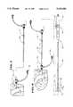
- FIG. 2is a side view of endocardial mapping system shown in FIG. 1, with portions fragmented and in section, showing the electrode-carrying basket in a collapsed condition before deployment inside the heart chamber;
- FIG. 3is an enlarged side view of the electrode-carrying basket and movable guide sheath shown in FIG. 2, with portions fragmented and in section, showing the electrode-carrying basket in a collapsed condition before deployment;
- FIG. 4is an enlarged side view of the electrode-carrying basket and movable guide sheath shown in FIG. 1, with portions fragmented and in section, showing the electrode-carrying basket in a deployed condition;
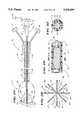
- FIG. 5is a side view of two splines of the basket, when deployed, showing the arrangement of electrodes on the splines;
- FIG. 6is a section view taken generally along line 6--6 in FIG. 1, showing the interior of the catheter body for the mapping probe;
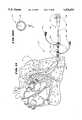
- FIG. 7is a plan view, with portions fragmented, of the introducer and outer guide sheath being introduced into the vein or artery access site in the process of forming the system shown in FIG. 1;
- FIG. 9is a plan view of the interior of the handle for the steerable catheter, partially broken away and in section, showing the mechanism for steering the distal tip of the catheter body;
- FIG. 10is a side view, with portions fragmented and in section, of advancing the steerable catheter body and outer guide sheath into the desired heart chamber;
- FIG. 10Ais a plan view of the interior of the hemostatic valve that systems embodying features of the invention use, showing the resilient slotted membrane present within the valve;
- FIG. 12is a side view, with portions fragmented and in section, of the mapping probe just before being introduced for advancement within the outer guide sheath, with the hemostat sheath fully forward to enclose the electrode-carrying basket;
- FIG. 13is a side view, with portions fragmented and in section, of the mapping probe being advanced through the hemostatic valve of the outer guide sheath, with the hemostat sheath fully forward to enclose the electrode-carrying basket;
- FIG. 16is an enlarged plan view of an alternative three dimensional structure, partially in section, that can be deployed using the system shown in FIG. 1, in use in association with a separate ablation probe;
- FIG. 17is an enlarged side section view of the structure shown in FIG. 16 in a collapsed condition before deployment;
- FIG. 19is an enlarged side section view of the structure shown in FIG. 18 in a collapsed condition before deployment;
- FIG. 20is a perspective view, partially fragmented, of an alternative embodiment of an outer guide sheath having a preformed complex curvature
- FIG. 22is a perspective view, partially fragmented, of an alternative embodiment of an outer guide sheath having a steerable distal tip
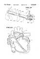
- FIG. 23is an enlarged plan view, partially in section, of the guide sheath shown in FIG. 22 deployed inside the heart chamber and in use in association with a separate ablation probe;
- FIG. 24is a plan view, with portions fragmented and in section, of an integrated mapping and ablation system that embodies the features of the invention.
- FIGS. 25 and 26are enlarged side elevation views of the electrode-carrying basket of the mapping probe that the system shown in FIG. 24 uses, showing the range of movement of the steerable ablating element carried within the basket;
- FIG. 28is an end elevation view, taken generally along line 28--28 in FIG. 26, of the electrode-carrying basket of the mapping probe that the system shown in FIG. 24 uses, showing the range of movement of the steerable ablating element carried within the basket;
- FIG. 29is an enlarged side section view of the distal end of the electrode-carrying basket of the mapping probe that the system shown in FIG. 24 uses, showing the basket in a collapsed condition about the steerable ablating element before deployment;
- FIG. 30is an end section view of the collapsed basket, taken generally along line 30--30 in FIG. 29;
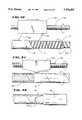
- FIG. 31is a side section view of the multiple layer catheter body of the mapping probe used in the system shown in FIG. 24;
- FIG. 32is a perspective view of the multiple layers of the catheter body shown in section in FIG. 31;
- FIG. 33is a view, partially in section, showing the formation of the first layer of the multiple layer catheter body shown in FIGS. 31 and 32;
- FIG. 34is a view, partially in section, showing the formation of the second layer of the multiple layer catheter body shown in FIGS. 31 and 32;
- FIG. 35is a view showing the formation of the third layer of the multiple layer catheter body shown in FIGS. 31 and 32;
- FIG. 36is a view showing the formation of the fourth layer of the multiple layer catheter body shown in FIGS. 31 and 32;
- FIGS. 37 and 38are views showing the formation of the fifth and final layer of the multiple layer catheter body shown in FIGS. 31 and 32.
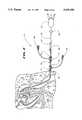
- FIG. 1shows an endocardial mapping system that embodies features of the invention, when deployed and ready for use within a selected region 12 inside the heart.
- the Figuresgenerally show the selected region 12 to be the left ventricle of the heart. However, it should be noted that the heart shown in the Figures is not anatomically accurate. The Figures show the heart in diagrammatic form to demonstrate the features of the invention.
- the system 10When deployed, the system 10 includes an introducer 14, an outer guide sheath 16, and a mapping probe 18.
- the introducer 14establishes access to a vein or artery.
- the outer guide sheath 16enters the access through the introducer 14.
- the guide sheath 16extends through the vein or artery to enter the selected heart chamber 12.
- the introducer 14 and the outer sheath 16establish a passageway that guides the mapping probe 18 through the access vein or artery and into the selected heart chamber 12.
- the mapping probe 18has a handle 20 (which FIG. 12 shows in its entirety), an attached flexible catheter body 22, and a movable hemostat sheath 30 with associated carriage 52.
- the distal end of the catheter body 22carries a three dimensional structure 24.
- the structure 24takes the form of a basket.
- FIGS. 16 and 18show alternative structures, which will be described in greater detail later.
- the three dimensional structure of the basket 24includes an exterior surface 27 that encloses an open interior area 25.
- the basket 24carries a three dimensional array of electrodes 26 on its exterior surface 27 (see FIG. 4 also).
- FIG. 1shows, when deployed inside the heart chamber 12, the exterior surface 27 of the basket 24 holds the electrodes 26 against the endocardial surface.
- the outer guide sheath 16When fully deployed, the outer guide sheath 16 holds the catheter body 22.
- the sheath 16is made from an inert plastic material. In the preferred embodiment, the sheath 16 is made from a nylon composite material.
- the sheath 16has an inner diameter that is greater than the outer diameter of the catheter body 22. As a result, the sheath 16 can slide along the catheter body 22.
- the proximal end of the sheath 16includes a handle 17.
- the handle 17helps the user slide the sheath 16 along the catheter body 22, as the arrows in FIGS. 1 and 2 depict.
- FIGS. 1 and 2show the range of sheath movement.
- FIGS. 2 and 3show forward movement of the handle 17 (i.e., toward the introducer 14) advances the distal end of the slidable sheath 16 upon the basket 24.
- the slidable sheath 16captures and collapses the basket 24 (as FIG. 3 also shows in greater detail). In this position, the distal end of the sheath 16 entirely encloses the basket 24.
- FIGS. 1 and 4show, rearward movement of the handle 17 (i.e., away from the introducer 14) retracts the slidable sheath 16 away from the basket 24. This removes the compression force.
- the basket 24opens to assume a prescribed three dimensional shape.
- the basket electrodes 26record the electrical potentials in myocardial tissue.
- Connectors 44 on the handle 20attach to an external processor (not shown). The processor derives the activation times, the distribution, and the waveforms of the potentials recorded by the basket electrodes 26.
- the basket 24can be variously constructed.
- the basket 24comprises a base member 32 and an end cap 34.
- Generally flexible splines 36extend in a circumferentially spaced relationship between the base member 32 and the end cap 34.
- eight splines 36form the basket 24. However, additional or fewer splines 36 could be used, depending upon application.
- the splines 36are made of a resilient inert material, like Nitinol metal or silicone rubber.
- the splines 36are connected between the base member 32 and the end cap 34 in a resilient, pretensed condition.
- the resilient splines 36bend and conform to the tissue surface they contact. As FIGS. 2 and 3 show, the splines 36 also collapse into a closed, compact bundle in response to an external compression force.
- each spline 36carries eight electrodes 26.
- additional or fewer electrodes 26can be used.
- one or more electrodes 26can also be located on the end cap 34.
- the electrodes 26can be arranged in thirty-two bi-polar pairs, or as sixty-four uni-polar elements.
- the electrodes 26are made of platinum or gold plated stainless steel.
- the signal wires 38extend down the associated spline 36, by the base member 32, and into the catheter body 22.
- An inert plastic sheath 40preferably covers each spline 36 to enclose the signal wires 38 (see FIGS. 4 and 5).
- the sheath 40is made of polyurethane material.
- each connectorcontains thirty-two pins to service thirty-two signal wires.
- the connectors 44attach to the external processor.
- the catheter body 22also includes an inner sleeve that forms a central lumen 46.
- the wire bundles 42are oriented in an equally spaced array about this lumen 46.
- the sleeve of the central lumen 46is made of a Teflon material.
- a first region 54 on the proximal end of each spline 36is free of electrodes 26.
- a second region 56 on the distal end of each spline 36is also free of electrodes 26.
- FIGS. 7 to 14show the details of introducing the system 10 into the heart chamber 12.
- the system 10includes a steerable catheter 60 (see FIG. 8) to facilitate the introduction and positioning of the outer guide sheath 16.
- the catheter 60directs the introduction of the outer guide sheath 16, which is otherwise free of any onboard steering mechanism.
- the guide sheath 16in turn, directs the introduction of the mapping probe 18, which is likewise free of any onboard steering mechanism.
- the steering mechanismwould also have to be of sufficient strength to deflect the entire structure of the basket 24 when in a collapsed condition.
- a separate, dedicated steerable catheter 60permits the introduction of the entire system 10 through the access vessel and into the heart chamber using an outer guide sheath of about only 10 French.
- the catheter body 22 of the mapping probe 18can also be significantly smaller, being on the order of 6 to 8 French.
- a smaller steering mechanismcan also be used, because only the outer sheath 16 needs to be steered.
- the introducer 14has a skin-piercing cannula 62.
- the physicianuses the cannula 62 to establish percutaneous access into the selected vein or artery (which is typically the femoral vein or artery).
- the other end of the introducer 14includes a conventional hemostatic valve 64.
- the valve 64includes a resilient slotted membrane 65 (as FIG. 10A shows).
- the slotted membrane 65blocks the outflow of blood and other fluids from the access.
- the slot in the membrane 65yields to permit the introduction of the outer guide sheath 16 through it.
- the resilient membrane 65conforms about the outer surface of the sheath 16, thereby maintaining a fluid tight seal.
- the introducer 14also includes a flushing port 66 for introducing anticoagulant or other fluid at the access site.
- the steerable catheter 60includes a catheter body 68 having a steerable tip 70 at its distal end.
- a handle 72is attached to the proximal end of the catheter body 68.
- the handle 12encloses a steering mechanism 74 for the distal tip 70.
- the steering mechanism 74can vary. In the illustrated embodiment (see FIG. 9), the steering mechanism is the one shown in Copending U.S. application Ser. No. 07/789,260, which is incorporated by reference.
- the steering mechanism 74 of this constructionincludes a rotating cam wheel 76 within the handle 72.
- An external steering lever 78rotates the cam wheel.
- the cam wheel 76holds the proximal ends of right and left steering wires 80.
- the steering wires 80extend along the associated left and right side surfaces of the cam wheel 76 and through the catheter body 68.
- the steering wires 80connect to the left and right sides of a resilient bendable wire or spring (not shown) that deflects the steerable distal tip 70 of the catheter body 68.
- FIG. 8shows, forward movement of the steering lever 80 bends the distal tip 70 down. Rearward movement of the steering lever 80 rearward bends the distal tip 70 up.
- the steerable distal tip 70can also be bent out of a normal coaxial relationship with the catheter body 68 using custom shaped wire stiffeners 71.
- the stiffeners 71create a pre-formed, complex curve configuration. The complex curvature simplifies access to difficult-to-reach locations within the heart, such as the aortic approach through the left ventricle to the left atrium.
- FIGS. 10 and 11show the details of using the steerable catheter 60 to guide the outer sheath 16 into position.
- the outer guide sheath 16includes an interior bore 82 that receives the steerable catheter body 68 of the catheter 60. The physician can slide the outer guide sheath 16 along the steerable body 68 of the catheter 60.
- the handle 17 of the outer sheath 16includes a conventional hemostatic valve 84.
- the valve 84like the valve 64, includes a resilient slotted membrane 65 (as FIG. 10A shows) that blocks the outflow of blood and other fluids.
- the slotted membrane 65yields to permit the introduction of the body 22 of the mapping probe 18 through it.
- the membrane 65conforms about the outer surface of the body 22 to maintain a fluid tight seal.
- valves 64 and 84provide an effective hemostatic system that allows a procedure to be performed in a clean and relatively bloodless manner.
- the steerable catheter body 68enters the bore 82 of the guide sheath 16 through the valve 84, as FIG. 10 shows.
- the handle 17 of the outer sheath 16also preferably includes a flushing port 28 for the introduction of an anticoagulant or saline into the interior bore 82.
- the physicianadvances the catheter body 68 and the outer guide sheath 16 together through the access vein or artery.
- the physicianretains the sheath handle 17 near the catheter handle 72 to keep the catheter tip 70 outside the distal end of the outer sheath 16.
- the physiciancan operate the steering lever 78 to remotely point and steer the distal end 70 of the catheter body 68 while jointly advancing the catheter body 68 and guide sheath 16 through the access vein or artery.
- the physiciancan observe the progress of the catheter body 68 using fluoroscopic or ultrasound imaging, or the like.
- the outer sheath 16can include an radio-opaque compound, such a barium, for this purpose.
- a radioopaque markercan be placed at the distal end of the outer sheath 16.
- the physicianwithdraws the steerable catheter body 68 from the outer guide sheath 16.
- FIG. 12shows, before introducing the mapping probe 18, the physician advances the hemostat sheath 30, by pushing on the carriage 52.
- the sheath 30captures and collapses the basket 24.
- the physicianintroduces the hemostat sheath 30, with enclosed basket 24, through the hemostatic valve 84 of the outer sheath handle 17.
- the hemostat sheath 30protects the basket electrodes 26 from damage during insertion through the valve 84.
- FIG. 14shows, when the catheter body 22 is advanced approximately three inches into the guide sheath 16, the physician pulls back on the sheath carriage 52 to withdraw the hemostat sheath 30 from the valve 84.
- the hemostat valve 84seals about the catheter body 22.
- the guide sheath 16now itself encloses the collapsed basket 24.
- the physiciancan again collapse the basket 24 (by pushing forward on the handle 17), as FIG. 2 shows.
- the physiciancan then rotate the sheath 16 and probe 18 to change the angular orientation of the basket electrodes 26 inside the chamber 12, without contacting and perhaps damaging endocardial tissue.
- the physiciancan then redeploy the basket 24 in its new orientation by pulling back on the handle 17, as FIG. 1 shows.
- the physiciananalyses the signals received from the basket electrodes 26 to locate likely efficacious sites for ablation.
- the physiciancan now takes steps to ablate the myocardial tissue areas located by the basket electrodes 26.
- the physiciancan accomplish this result by using an electrode to thermally destroy myocardial tissue, either by heating or cooling the tissue.
- the physiciancan inject a chemical substance that destroys myocardial tissue.
- the physiciancan use other means for destroying myocardial tissue as well.
- the illustrated and preferred embodimentaccomplishes ablation by using an endocardial electrode to emit energy that heats myocardial tissue to thermally destroy it.
- the energyis transmitted between the endocardial electrode and an exterior indifferent electrode on the patient.
- the type of ablating energycan vary. It can, for example, be radio frequency energy or microwave energy.
- the ablating energyheats and thermally destroys the tissue to form a lesion, thereby restoring normal heart rhythm.
- Ablating energycan be conveyed to one or more electrodes 26 carried by the basket 24.
- one or more of the sensing electrodes 26 on the basket 24can also be used for tissue ablation.
- an external steerable ablating probe 150can be used in association with the basket 24.
- the physiciansteers the probe 150 under fluoroscopic control to maneuver the ablating element 152 into the basket 24. Once inside the basket 24, the physician steers the ablating element 152 into contact with the tissue region identified by the basket electrodes 26 as the likely efficacious site for ablation. The physician then conveys ablating energy to the element 152.
- the basket 24serves, not only to identify the likely ablation sites, but also to stabilize the external ablating probe 150 within a confined region within the heart chamber 12.
- the structure 154comprises a single length of inert wire material, such a Nitinol metal wire, preformed into a helical array. While the particular shape of the helical array can vary, in the illustrated embodiment, the array has a larger diameter in its midsection than on its proximal and distal ends.
- the structure 154can be used to stabilize the external steerable ablation probe 150 in the same fashion as the basket 24 shown in FIG. 15 does.
- the structure 154can also carry electrodes 156, like the basket 24, for mapping and/or ablating purposes.
- the structure 154can be collapsed in response to an external compression force.
- the distal end of the slidable guide sheath 16provides this compression force to retract and deploy the structure 154 inside the selected heart chamber, just like the basket structure 24.
- the loop 160nests within the loop 162.
- the distal ends of the nested loops 160 and 162are not joined. Instead, the nested loops 160 and 162 are free to flex and bend independently of each other.
- the loops 160 and 162form right angles to each other. Of course, other angular relationships can be used. Additional independent loops can also be included to form the structure 158.
- the loop structure 158can be used to stabilize the external steerable probe 150 in the same fashion as the structures 24 and 154 shown in FIGS. 15 and 16 do.
- One or more of the loops 160 and 162can also carry electrodes 164 for mapping and/or ablating purposes.
- the structure 158can be collapsed in response to an external compression force, as FIG. 19 shows.
- the distal end of the slidable guide sheath 16provides this compression force to retract and deploy the structure 158 inside the selected heart chamber 12.
- FIGS. 20 and 21show an alternative embodiment of a guide sheath 166 that can be used in association with the introducer 14 to locate a steerable ablation probe 168 inside the selected heart chamber 12.
- the guide sheath 166is preformed with a memory that assumes a prescribed complex curvature in the absence of an external stretching or compressing force.
- FIG. 20shows in phantom lines the guide sheath 166 in a stretched or compressed condition, as it would be when being advanced along the steerable catheter body 68 through the access vein or artery.
- the sheath 166Upon entering the less constricted space of the heart chamber 12, as FIG. 21 shows, the sheath 166 assumes its complex curved condition.
- the complex curveis selected to simplify access to difficult-to-reach locations within the heart, such as through the inferior vena cava into the right ventricle, as FIG. 21 shows.
- the sheath 166preferably includes a conventional hemostatic valve 169 on its proximal end.
- the hemostatic valve 169includes a resilient slotted membrane to block the outflow of fluids, while allowing passage of a catheter body.
- FIG. 21shows the sheath 166 in use in association with a steerable ablating probe 168, which enters the sheath 166 through the hemostatic valve 169.
- the sheath 166like the sheath 16, guides the probe 168 through the access vein or artery into the heart chamber 12.
- the complex curvature of the sheath 166more precisely orients the steerable ablation probe 168 with respect to the intended ablation site than the sheath 16. As FIG. 21 shows, the complex curvature points the distal end of the sheath 166 in a general orientation toward the intended ablation site. This allows the physician to finally orient the ablating element 170 with the intended site using fine steering adjustments under fluoroscopic control.
- FIGS. 20 and 21uses the preformed sheath 166 to provide relatively coarse steering guidance for the ablation probe 168 into the heart chamber 12.
- the sheath 166simplifies the task of final alignment and positioning of the ablating element with respect to the precise ablation region, which the physician can accomplish using a few, relatively fine remote steering adjustments.
- FIGS. 22 and 23show yet another alternative embodiment of a guide sheath 172 that can be used in association with the introducer 14 to locate an ablation probe 174 inside the selected heart chamber 12.
- the guide sheath 172includes a sheath body 176 with a steerable distal tip 178.
- the sheath body 176is extruded to include a center guide lumen 180 and two side lumens 182.
- Steering wires 183extend through the side lumens 182, which are located near the exterior surface of the body 176.
- the distal ends of the steering wires 183are attached to the side lumens 182 at the distal tip 178 of the sheath body 176.
- the proximal ends of the steering wires 183are attached to a steering mechanism 186 within a handle 188 attached at the proximal end of the sheath body 176.
- the steering mechanism 186can vary.
- the mechanism 186is the rotating cam arrangement shown in FIG. 9.
- the steering mechanism 186includes an exterior steering lever 190. Fore and aft movement of the steering lever 190 deflects the distal tip 178 of the guide sheath 176, as FIG. 22 shows.
- the sheath 172preferably includes a conventional hemostatic valve 185 on its proximal end to block the outflow of fluids while allowing the passage of a catheter body.
- the steerable guide sheath 172is used in association with the introducer 14.
- the physiciansteers the guide sheath 172 through the access vein or artery and into the selected heart chamber 12 under fluoroscopic control, as FIG. 23 shows.
- the physicianthen introduces the probe 174 through the center guide lumen 180.
- the probe 174can carry a mapping structure, like those shown in FIGS. 1; 16; and 18.
- the probe 174carries an ablating element 192.
- the catheter body 194 of the probe 174need not include a steering mechanism.
- the catheter body 194need only carry the electrical conduction wires its function requires.
- the catheter body 194can therefore be downsized.
- the absence of a steering mechanismfrees space within the catheter body 194 for additional or larger electrical conduction wires, as ablating elements using coaxial cable or temperature sensing elements may require.
- FIG. 24shows an integrated system 86 for performing endocardial mapping and ablation.
- the integrated system 86includes a mapping probe 18 with sensing electrodes 26 carried by a three dimensional basket 24.
- the integrated system 86includes, as an integral part, a steerable ablating element 88 that is carried within the open interior area 25 of the basket 24.
- the ablating element 88can be moved relative to the sensing electrodes 26 in three principal directions. First, the ablating element 88 moves along the axis of the mapping probe body 96. Second, the ablating element 88 moves rotationally about the axis of the mapping probe body 96. Third, the ablating element 88 moves in a direction normal to the axis of the mapping probe body 96. FIGS. 25 to 28 show the range of movement the preferred embodiment provides.
- Movement of the ablating element 88does not effect the contact between the sensing electrodes 26 and the endocardial tissue.
- the electrodes 26 and the ablating element 88are capable of making contact with endocardial tissue independent of each other.
- the system 86includes a steerable ablation catheter 90 that is an integral part of the mapping probe 18.
- the ablation catheter 90includes a steering assembly 92 with a steerable distal tip 84.
- the steerable distal tip 84carries the ablating element 88.
- the mapping probe 18includes a catheter body 96 through which the steering assembly 92 of the ablation catheter 90 passes during use.
- the proximal end of the catheter body 96communicates with an opening at the rear of the handle 20.
- the distal end of the catheter body 96opens into the interior area 25 of the basket 24.
- a conventional hemostatic valve 95is located at this junction.
- the valve 95includes a resilient slotted membrane that blocks the outflow of fluid while allowing the passage of the steering assembly 92.
- the proximal end of the steering assembly 92 of the ablation catheter 90is attached to a handle 98 (as FIG. 24 best shows).
- a handle 98By pulling and pushing the handle 98, the physician moves the ablating element 88 along the axis of the mapping probe body 96.
- the physicianrotates the ablating element 88 about the axis of the mapping probe body 96.
- the handle 98further encloses a steering mechanism 74 for the tip 84.
- the steering mechanism 74 for the ablating catheter 90is the same as the steering mechanism 74 for the catheter 60 used in the first described system 10, and thereby shares the same reference number.
- FIG. 27generally shows, movement of the steering lever 78 forward bends the distal tip 84, and with it, the ablating element 88, down. Movement of the steering lever 78 rearward bends the distal tip 84, and with it, the ablating element 88, up.
- the handle 98By rotating and moving the handle 98 in these ways, it is possible to maneuver the ablating element 88 under fluoroscopic control through the basket 24 into contact with any point of the endocardial surface of the chamber 12.
- the ablating 88can be moved through the basket 24 to tissue locations either in contact with the exterior surface of the basket 24 or laying outside the reach of the basket 24 itself.
- a cable 100 with an outer insulating sheathis attached to the ablating element 88 (see FIGS. 27 and 29).
- the electrically insulated cable 100extends down the length of the steering assembly 92.
- the cable 100conveys ablating energy to the element 88.
- a plug 102 attached to the proximal end of the cable 100extends outside the handle 98 for connection to a source of ablating energy (not shown).
- the integrated mapping and ablation system 86 shown in FIG. 24shares various other components and methodologies with the first described system 10. Elements shared by the two embodiments are given common reference numbers.
- the integrated system 86uses the same introducer 14 to establish an access. It also uses the same outer guide sheath 16 and the same steerable catheter 60 (with steerable catheter body 68) to position the outer guide sheath 16. The outer sheath 16 is inserted through the introducer 14 and positioned inside the heart by the steerable catheter body 68 in the same fashion as earlier described (and as shown in FIGS. 10 and 11).
- the physicianguides the mapping probe 18 with integral ablating catheter 90 into position through the outer sheath 16.
- the physicianthen deploys the basket 24, freeing the ablating element 88 for use, as FIG. 24 shows.
- the basket structurecontacts the surrounding endocardial tissue to hold and stabilize the ablating element 88 in a desired confined region within the heart while the basket electrodes 26 provide mapping signals.
- the ablating element 88can be remotely steered to sites identified by the basket electrodes 26 (as FIG. 26 shows). Ablating energy can then be applied to thermally destroy the tissue.
- the catheter body 96includes a center tube 106 made from a plastic material, such as Pebax tubing.
- the center tube 106has an interior bore 108 of a size that accommodates the steering assembly 92 of the ablating catheter 90.
- the catheter body 96includes two layers 110 and 112 of copper signal wire 38 (42 gauge) wrapped about the center tube 106.
- Each copper signal wire 38carries an outer insulating sheath.
- the two layers 110 and 112are separated from each other by an insulation layer 114 of Teflon plastic or the like.
- the layer 114provides an added measure of insulation between the wires 38, particularly in regions where point contact between the overlapping wire layers 110 and 112 could occur.
- the catheter body 96further includes a metalized plastic layer 116 (such as metalized polyamide) that surrounds the second layer 112 of signal wires 38.
- the layer 116protection against electromagnetic interference (EMI).
- the layer 116is, in turn, enclosed within an outer plastic tube 118 of a material such as Pebax.
- the center tube 106is fastened by clamps 124 to a mandrel 126.
- the mandrel 126is rotated during the assembly process. In the illustrated embodiment, the mandrel 126 rotates in a clockwise direction.
- the wire groups dispensed by the holder 128are helically wrapped about the center tube 106. This forms the first layer 110 of signal wires 38 about the center tube 106.
- FIG. 34shows, another holder 132 is advanced by the lead screw 130 along the axis of the rotating mandrel 126.
- the holder 132helically wraps insulating Teflon plastic tape 134 about the first layer 110 of signal wires 38. This forms the added insulating layer 114 of the catheter body 96.
- FIG. 37shows, another holder 140 advanced by the lead screw 130 dispenses adhesive 142 upon the metalized layer 116.
- the outer sleeve 118is pulled over the adhesive 142 to complete the structure of the multiple layer catheter body 96.
Landscapes
- Health & Medical Sciences (AREA)
- Life Sciences & Earth Sciences (AREA)
- Engineering & Computer Science (AREA)
- Biomedical Technology (AREA)
- Veterinary Medicine (AREA)
- Public Health (AREA)
- General Health & Medical Sciences (AREA)
- Animal Behavior & Ethology (AREA)
- Heart & Thoracic Surgery (AREA)
- Nuclear Medicine, Radiotherapy & Molecular Imaging (AREA)
- Surgery (AREA)
- Cardiology (AREA)
- Molecular Biology (AREA)
- Pathology (AREA)
- Physics & Mathematics (AREA)
- Medical Informatics (AREA)
- Radiology & Medical Imaging (AREA)
- Biophysics (AREA)
- Plasma & Fusion (AREA)
- Physiology (AREA)
- Otolaryngology (AREA)
- Vascular Medicine (AREA)
- Surgical Instruments (AREA)
- Media Introduction/Drainage Providing Device (AREA)
Abstract
Description
This application claims, as a divisional application pursuant to 37 C.F.R. 1.78, the benefit of the filing date of application Ser. No. 08/033,640, filed Mar. 16, 1993, entitled "Multiple Layer Guide Body for Cardiac Mapping and Ablation Catheter" now abandoned.
The invention relates to systems and methods for mapping and ablating the interior regions of the heart for treatment of cardiac conditions.
Physicians make use of catheters today in medical procedures to gain access into interior regions of the body to ablate targeted tissue areas. It is important for the physician to be able to carefully and precisely control the position of the catheter and its emission of energy within the body during tissue ablation procedures.
The need for careful and precise control over the catheter is especially critical during procedures that ablate tissue within the heart. These procedures, called electrophysiological therapy, are becoming more widespread for treating cardiac rhythm disturbances.
During these procedures, a physician steers a catheter through a main vein or artery into the interior region of the heart that is to be treated. The physician then further manipulates a steering mechanism to place the electrode carried on the distal tip of the catheter into direct contact with the tissue that is to be ablated. The physician directs energy from the electrode through tissue to an indifferent electrode (in a uni-polar electrode arrangement) or to an adjacent electrode (in a bi-polar electrode arrangement) to ablate the tissue and form a lesion.
Cardiac mapping can be used before ablation to locate aberrant conductive pathways within the heart. The aberrant conductive pathways constitute peculiar and life threatening patterns, called dysrhythmias. Mapping identifies regions along these pathways, called foci, which are then ablated to treat the dysrhythmia.
There is a need for cardiac mapping and ablation systems and procedures that can be easily deployed with a minimum of manipulation and effort.
There is also a need for systems and procedures that are capable of performing cardiac mapping in tandem with cardiac ablation. Such multipurpose systems must also be easily introduced into the heart. Once deployed, such multipurpose systems also must be capable of mapping and ablating with a minimum of manipulation and effort.
A principal objective of the invention is to provide improved probes to carry out cardiac mapping and/or cardiac ablation procedures quickly and accurately.
Another principal objective of the invention is to provide improved probes that integrate mapping and ablation functions.
The invention provides a probe for use within the heart to contact endocardial tissue. The probe includes a catheter tube having a distal end that carries a first electrode element. The probe also includes a second electrode element on the distal end. The second electrode element defines a three-dimensional structure that extends along an axis and that has an open interior. The probe includes a mechanism for moving the first electrode element within the open interior of the second electrode element in a first direction along the axis of the second electrode element, in a second direction rotating about the axis of the second electrode element, and in a third direction normal to the axis of the second electrode element.
In a preferred embodiment, the movable first electrode element serves to ablate myocardial tissue. The second electrode element independently serves to sense electrical activity in endocardial tissue.
Other features and advantages of the inventions are set forth in the following Description and Drawings, as well as in the appended Claims.
FIG. 1 is a side view, with portions fragmented and in section, of an endocardial mapping system that embodies the features of the invention, shown deployed and ready for use inside a heart chamber;
FIG. 2 is a side view of endocardial mapping system shown in FIG. 1, with portions fragmented and in section, showing the electrode-carrying basket in a collapsed condition before deployment inside the heart chamber;
FIG. 3 is an enlarged side view of the electrode-carrying basket and movable guide sheath shown in FIG. 2, with portions fragmented and in section, showing the electrode-carrying basket in a collapsed condition before deployment;
FIG. 4 is an enlarged side view of the electrode-carrying basket and movable guide sheath shown in FIG. 1, with portions fragmented and in section, showing the electrode-carrying basket in a deployed condition;
FIG. 5 is a side view of two splines of the basket, when deployed, showing the arrangement of electrodes on the splines;
FIG. 6 is a section view taken generally alongline 6--6 in FIG. 1, showing the interior of the catheter body for the mapping probe;
FIG. 7 is a plan view, with portions fragmented, of the introducer and outer guide sheath being introduced into the vein or artery access site in the process of forming the system shown in FIG. 1;
FIG. 8 is a plan view of the introducer, the outer guide sheath, and the steerable catheter being introduced into the access site in the process of forming the system shown in FIG. 1;
FIG. 9 is a plan view of the interior of the handle for the steerable catheter, partially broken away and in section, showing the mechanism for steering the distal tip of the catheter body;
FIG. 10 is a side view, with portions fragmented and in section, of advancing the steerable catheter body and outer guide sheath into the desired heart chamber;
FIG. 10A is a plan view of the interior of the hemostatic valve that systems embodying features of the invention use, showing the resilient slotted membrane present within the valve;
FIG. 11 is a side view, with portions fragmented and in section, of the guide sheath and the steerable catheter body advanced into the deployment position within the desired heart region;
FIG. 12 is a side view, with portions fragmented and in section, of the mapping probe just before being introduced for advancement within the outer guide sheath, with the hemostat sheath fully forward to enclose the electrode-carrying basket;
FIG. 13 is a side view, with portions fragmented and in section, of the mapping probe being advanced through the hemostatic valve of the outer guide sheath, with the hemostat sheath fully forward to enclose the electrode-carrying basket;
FIG. 14 is a side view, with portions fragmented and in section, of the mapping probe after advancement through the hemostatic valve of the outer guide sheath, with the hemostat sheath pulled back to uncover the electrode-carrying basket;
FIG. 15 is an enlarged view, with portions in section, of the electrode-carrying basket deployed inside the heart chamber in use in association with a separate ablation probe;
FIG. 16 is an enlarged plan view of an alternative three dimensional structure, partially in section, that can be deployed using the system shown in FIG. 1, in use in association with a separate ablation probe;
FIG. 17 is an enlarged side section view of the structure shown in FIG. 16 in a collapsed condition before deployment;
FIG. 18 is an enlarged plan view of an alternative three dimensional structure that can be deployed using the system shown in FIG. 1, in use in association with a separate ablation probe;
FIG. 19 is an enlarged side section view of the structure shown in FIG. 18 in a collapsed condition before deployment;
FIG. 20 is a perspective view, partially fragmented, of an alternative embodiment of an outer guide sheath having a preformed complex curvature;
FIG. 21 is an enlarged plan view, partially in section, of the guide sheath shown in FIG. 20 deployed inside the heart chamber and in use in association with a separate steerable ablation probe;
FIG. 22 is a perspective view, partially fragmented, of an alternative embodiment of an outer guide sheath having a steerable distal tip;
FIG. 23 is an enlarged plan view, partially in section, of the guide sheath shown in FIG. 22 deployed inside the heart chamber and in use in association with a separate ablation probe;
FIG. 24 is a plan view, with portions fragmented and in section, of an integrated mapping and ablation system that embodies the features of the invention;
FIGS. 25 and 26 are enlarged side elevation views of the electrode-carrying basket of the mapping probe that the system shown in FIG. 24 uses, showing the range of movement of the steerable ablating element carried within the basket;
FIG. 27 is a diagrammatic view of the integrated mapping and ablation system shown in FIG. 24;
FIG. 28 is an end elevation view, taken generally alongline 28--28 in FIG. 26, of the electrode-carrying basket of the mapping probe that the system shown in FIG. 24 uses, showing the range of movement of the steerable ablating element carried within the basket;
FIG. 29 is an enlarged side section view of the distal end of the electrode-carrying basket of the mapping probe that the system shown in FIG. 24 uses, showing the basket in a collapsed condition about the steerable ablating element before deployment;
FIG. 30 is an end section view of the collapsed basket, taken generally alongline 30--30 in FIG. 29;
FIG. 31 is a side section view of the multiple layer catheter body of the mapping probe used in the system shown in FIG. 24;
FIG. 32 is a perspective view of the multiple layers of the catheter body shown in section in FIG. 31;
FIG. 33 is a view, partially in section, showing the formation of the first layer of the multiple layer catheter body shown in FIGS. 31 and 32;
FIG. 34 is a view, partially in section, showing the formation of the second layer of the multiple layer catheter body shown in FIGS. 31 and 32;
FIG. 35 is a view showing the formation of the third layer of the multiple layer catheter body shown in FIGS. 31 and 32;
FIG. 36 is a view showing the formation of the fourth layer of the multiple layer catheter body shown in FIGS. 31 and 32; and
FIGS. 37 and 38 are views showing the formation of the fifth and final layer of the multiple layer catheter body shown in FIGS. 31 and 32.
FIG. 1 shows an endocardial mapping system that embodies features of the invention, when deployed and ready for use within a selectedregion 12 inside the heart.
The Figures generally show the selectedregion 12 to be the left ventricle of the heart. However, it should be noted that the heart shown in the Figures is not anatomically accurate. The Figures show the heart in diagrammatic form to demonstrate the features of the invention.
When deployed, thesystem 10 includes anintroducer 14, anouter guide sheath 16, and amapping probe 18.
As FIG. 1 shows, theintroducer 14 establishes access to a vein or artery. Theouter guide sheath 16 enters the access through theintroducer 14. Theguide sheath 16 extends through the vein or artery to enter the selectedheart chamber 12.
Together, theintroducer 14 and theouter sheath 16 establish a passageway that guides themapping probe 18 through the access vein or artery and into the selectedheart chamber 12.
Themapping probe 18 has a handle 20 (which FIG. 12 shows in its entirety), an attachedflexible catheter body 22, and amovable hemostat sheath 30 with associatedcarriage 52.
The distal end of thecatheter body 22 carries a threedimensional structure 24. In FIG. 1, thestructure 24 takes the form of a basket. FIGS. 16 and 18 show alternative structures, which will be described in greater detail later.
The three dimensional structure of thebasket 24 includes anexterior surface 27 that encloses an openinterior area 25. Thebasket 24 carries a three dimensional array ofelectrodes 26 on its exterior surface 27 (see FIG. 4 also).
As FIG. 1 shows, when deployed inside theheart chamber 12, theexterior surface 27 of thebasket 24 holds theelectrodes 26 against the endocardial surface.
When fully deployed, theouter guide sheath 16 holds thecatheter body 22. Thesheath 16 is made from an inert plastic material. In the preferred embodiment, thesheath 16 is made from a nylon composite material.
Thesheath 16 has an inner diameter that is greater than the outer diameter of thecatheter body 22. As a result, thesheath 16 can slide along thecatheter body 22.
The proximal end of thesheath 16 includes ahandle 17. Thehandle 17 helps the user slide thesheath 16 along thecatheter body 22, as the arrows in FIGS. 1 and 2 depict. FIGS. 1 and 2 show the range of sheath movement.
As FIGS. 2 and 3 show, forward movement of the handle 17 (i.e., toward the introducer 14) advances the distal end of theslidable sheath 16 upon thebasket 24. Theslidable sheath 16 captures and collapses the basket 24 (as FIG. 3 also shows in greater detail). In this position, the distal end of thesheath 16 entirely encloses thebasket 24.
As FIGS. 1 and 4 show, rearward movement of the handle 17 (i.e., away from the introducer 14) retracts theslidable sheath 16 away from thebasket 24. This removes the compression force. Thebasket 24 opens to assume a prescribed three dimensional shape.
Thebasket electrodes 26 record the electrical potentials in myocardial tissue.Connectors 44 on the handle 20 (see FIGS. 12 and 13) attach to an external processor (not shown). The processor derives the activation times, the distribution, and the waveforms of the potentials recorded by thebasket electrodes 26.
Thebasket 24 can be variously constructed. In the illustrated and preferred embodiment (best shown by FIG. 4), thebasket 24 comprises abase member 32 and anend cap 34. Generallyflexible splines 36 extend in a circumferentially spaced relationship between thebase member 32 and theend cap 34.
In the illustrated embodiment, eightsplines 36 form thebasket 24. However, additional orfewer splines 36 could be used, depending upon application.
In this arrangement, thesplines 36 are made of a resilient inert material, like Nitinol metal or silicone rubber. Thesplines 36 are connected between thebase member 32 and theend cap 34 in a resilient, pretensed condition.
The resilient splines 36 bend and conform to the tissue surface they contact. As FIGS. 2 and 3 show, thesplines 36 also collapse into a closed, compact bundle in response to an external compression force.
In the illustrated embodiment (as FIGS. 4 and 5 best show), eachspline 36 carries eightelectrodes 26. Of course, additional orfewer electrodes 26 can be used. Furthermore, one ormore electrodes 26 can also be located on theend cap 34.
Theelectrodes 26 can be arranged in thirty-two bi-polar pairs, or as sixty-four uni-polar elements. In the preferred embodiment, theelectrodes 26 are made of platinum or gold plated stainless steel.
Asignal wire 38 made from a highly conductive metal, like copper, leads from eachelectrode 26. Thesignal wires 38 extend down the associatedspline 36, by thebase member 32, and into thecatheter body 22. An inertplastic sheath 40 preferably covers eachspline 36 to enclose the signal wires 38 (see FIGS. 4 and 5). In the preferred embodiment, thesheath 40 is made of polyurethane material.
The eightsignal wires 38 for eachspline 36 are twisted together to form acommon bundle 42. As FIG. 6 shows, the eightcommon bundle 42 are, in turn, passed through thecatheter body 22 of themapping probe 18. The common bundles 42 extend withincatheter body 22 and into the probe handle 20.
The sixty-foursignal wires 38 are distributed within the probe handle 20 to one or moreexternal connectors 44, as FIG. 12 shows. In the illustrated embodiment, each connector contains thirty-two pins to service thirty-two signal wires. The connectors 44.attach to the external processor.
As FIG. 6 shows, thecatheter body 22 also includes an inner sleeve that forms acentral lumen 46. The wire bundles 42 are oriented in an equally spaced array about thislumen 46. In the preferred embodiment, the sleeve of thecentral lumen 46 is made of a Teflon material.
The proximal end of thecentral lumen 46 is attached to a flushingport 48 that extends outside thehandle 20, as FIG. 12 shows. The distal end of thecentral lumen 46 opens at thebase member 32 of thebasket 24. Anticoagulant or saline can be introduced through the flushingport 48 into theheart chamber 12 that thebasket 24 occupies.
In the illustrated and preferred embodiment (as FIG. 5 best shows), afirst region 54 on the proximal end of eachspline 36 is free ofelectrodes 26. Likewise, asecond region 56 on the distal end of eachspline 36 is also free ofelectrodes 26. These two fore andaft regions electrodes 26 in these regions may not uniformly provide reliable signals.
The eightelectrodes 26 on eachspline 36 are arranged in 4 groups of equally spaced pairs in athird region 58 between the twoend regions third region 58 uniformly makes stable surface contact with the endocardial tissue, creating reliable signals from theelectrodes 26.
FIGS. 7 to 14 show the details of introducing thesystem 10 into theheart chamber 12.
Thesystem 10 includes a steerable catheter 60 (see FIG. 8) to facilitate the introduction and positioning of theouter guide sheath 16.
Thecatheter 60 directs the introduction of theouter guide sheath 16, which is otherwise free of any onboard steering mechanism. Theguide sheath 16, in turn, directs the introduction of themapping probe 18, which is likewise free of any onboard steering mechanism.
Use of aseparate catheter 60 for steering purposes results in a significant reduction in the overall size of the system components.
If themapping probe 18 carried its own onboard steering mechanism, thecatheter body 22 would have to be of sufficient size to accommodate it. Typically, this would require acatheter body 22 with a diameter of about 12-14 French (one French is 0.33 mm in diameter).
Furthermore, if carried onboard themapping probe 18, the steering mechanism would also have to be of sufficient strength to deflect the entire structure of thebasket 24 when in a collapsed condition.
According to this aspect of the invention, use of a separate, dedicatedsteerable catheter 60 permits the introduction of theentire system 10 through the access vessel and into the heart chamber using an outer guide sheath of about only 10 French. Thecatheter body 22 of themapping probe 18 can also be significantly smaller, being on the order of 6 to 8 French. In addition, a smaller steering mechanism can also be used, because only theouter sheath 16 needs to be steered.
As FIG. 7 shows, theintroducer 14 has a skin-piercingcannula 62. The physician uses thecannula 62 to establish percutaneous access into the selected vein or artery (which is typically the femoral vein or artery). The other end of theintroducer 14 includes a conventionalhemostatic valve 64.
Thevalve 64 includes a resilient slotted membrane 65 (as FIG. 10A shows). The slottedmembrane 65 blocks the outflow of blood and other fluids from the access. The slot in themembrane 65 yields to permit the introduction of theouter guide sheath 16 through it. Theresilient membrane 65 conforms about the outer surface of thesheath 16, thereby maintaining a fluid tight seal.
Theintroducer 14 also includes a flushingport 66 for introducing anticoagulant or other fluid at the access site.
As FIG. 8 shows, thesteerable catheter 60 includes acatheter body 68 having asteerable tip 70 at its distal end. Ahandle 72 is attached to the proximal end of thecatheter body 68. Thehandle 12 encloses asteering mechanism 74 for thedistal tip 70.
Thesteering mechanism 74 can vary. In the illustrated embodiment (see FIG. 9), the steering mechanism is the one shown in Copending U.S. application Ser. No. 07/789,260, which is incorporated by reference.
As FIG. 9 shows, thesteering mechanism 74 of this construction includes arotating cam wheel 76 within thehandle 72. Anexternal steering lever 78 rotates the cam wheel. Thecam wheel 76 holds the proximal ends of right and leftsteering wires 80.
Thesteering wires 80 extend along the associated left and right side surfaces of thecam wheel 76 and through thecatheter body 68. Thesteering wires 80 connect to the left and right sides of a resilient bendable wire or spring (not shown) that deflects the steerabledistal tip 70 of thecatheter body 68.
As FIG. 8 shows, forward movement of the steeringlever 80 bends thedistal tip 70 down. Rearward movement of the steeringlever 80 rearward bends thedistal tip 70 up. By rotating thehandle 70, thereby rotating thedistal tip 70, and thereafter manipulating the steeringlever 80 as required, it is possible to maneuver thedistal tip 70 virtually in any direction.
In an alternative arrangement (shown in phantom line view A in FIG. 8), the steerabledistal tip 70 can also be bent out of a normal coaxial relationship with thecatheter body 68 using custom shapedwire stiffeners 71. Thestiffeners 71 create a pre-formed, complex curve configuration. The complex curvature simplifies access to difficult-to-reach locations within the heart, such as the aortic approach through the left ventricle to the left atrium.
FIGS. 10 and 11 show the details of using thesteerable catheter 60 to guide theouter sheath 16 into position.
Theouter guide sheath 16 includes aninterior bore 82 that receives thesteerable catheter body 68 of thecatheter 60. The physician can slide theouter guide sheath 16 along thesteerable body 68 of thecatheter 60.
Thehandle 17 of theouter sheath 16 includes a conventionalhemostatic valve 84. Thevalve 84, like thevalve 64, includes a resilient slotted membrane 65 (as FIG. 10A shows) that blocks the outflow of blood and other fluids. Like thevalve 64, the slottedmembrane 65 yields to permit the introduction of thebody 22 of themapping probe 18 through it. At the same time, themembrane 65 conforms about the outer surface of thebody 22 to maintain a fluid tight seal.
Together, thevalves
In use, thesteerable catheter body 68 enters thebore 82 of theguide sheath 16 through thevalve 84, as FIG. 10 shows. Thehandle 17 of theouter sheath 16 also preferably includes a flushingport 28 for the introduction of an anticoagulant or saline into the interior bore 82.
As FIG. 10 also shows, the physician advances thecatheter body 68 and theouter guide sheath 16 together through the access vein or artery. The physician retains the sheath handle 17 near the catheter handle 72 to keep thecatheter tip 70 outside the distal end of theouter sheath 16. In this way, the physician can operate the steeringlever 78 to remotely point and steer thedistal end 70 of thecatheter body 68 while jointly advancing thecatheter body 68 and guidesheath 16 through the access vein or artery.
The physician can observe the progress of thecatheter body 68 using fluoroscopic or ultrasound imaging, or the like. Theouter sheath 16 can include an radio-opaque compound, such a barium, for this purpose. Alternatively, a radioopaque marker can be placed at the distal end of theouter sheath 16.
This allows the physician to maneuver thecatheter body 68 through the vein or artery into the selectedinterior heart chamber 12, as FIG. 10 shows.
As FIG. 11 shows, when the physician locates thedistal end 70 of thecatheter body 68 in the desiredendocardial chamber 12, he/she slides the outer sheath handle 17 forward along thecatheter body 68, away from thehandle 72 and toward theintroducer 14. Thecatheter body 68 directs theguide sheath 16 fully into theheart chamber 12, coextensive with thedistal tip 70.
Holding thehandle 17 of theouter sheath 16, the physician withdraws thesteerable catheter body 68 from theouter guide sheath 16.
Thesystem 10 is now deployed in the condition generally shown in FIG. 12. As FIG. 12 shows, the guide sheath bore 82 establishes a passageway that leads directly from theintroducer 14 into the selectedheart chamber 12. Themapping probe 18 follows this passageway for deployment inside thechamber 12.
As FIG. 12 shows, before introducing themapping probe 18, the physician advances thehemostat sheath 30, by pushing on thecarriage 52. Thesheath 30 captures and collapses thebasket 24.
As FIG. 13 shows, the physician introduces thehemostat sheath 30, withenclosed basket 24, through thehemostatic valve 84 of theouter sheath handle 17. Thehemostat sheath 30 protects thebasket electrodes 26 from damage during insertion through thevalve 84.
As FIG. 14 shows, when thecatheter body 22 is advanced approximately three inches into theguide sheath 16, the physician pulls back on thesheath carriage 52 to withdraw thehemostat sheath 30 from thevalve 84. Thehemostat valve 84 seals about thecatheter body 22. Theguide sheath 16 now itself encloses thecollapsed basket 24.
As FIG. 2 shows, theouter sheath 16 directs thebasket 24 ofmapping probe 18 to the desired location inside theheart chamber 12. As FIG. 1 shows, the physician then moves thehandle 17 rearward. The distal end of thesheath 16 slides back to deploy thebasket 24 for use.
Once deployed, the physician can again collapse the basket 24 (by pushing forward on the handle 17), as FIG. 2 shows. The physician can then rotate thesheath 16 andprobe 18 to change the angular orientation of thebasket electrodes 26 inside thechamber 12, without contacting and perhaps damaging endocardial tissue. The physician can then redeploy thebasket 24 in its new orientation by pulling back on thehandle 17, as FIG. 1 shows.
The physician analyses the signals received from thebasket electrodes 26 to locate likely efficacious sites for ablation.
The physician can now takes steps to ablate the myocardial tissue areas located by thebasket electrodes 26. The physician can accomplish this result by using an electrode to thermally destroy myocardial tissue, either by heating or cooling the tissue. Alternatively, the physician can inject a chemical substance that destroys myocardial tissue. The physician can use other means for destroying myocardial tissue as well.
The illustrated and preferred embodiment accomplishes ablation by using an endocardial electrode to emit energy that heats myocardial tissue to thermally destroy it. The energy is transmitted between the endocardial electrode and an exterior indifferent electrode on the patient.
The type of ablating energy can vary. It can, for example, be radio frequency energy or microwave energy. The ablating energy heats and thermally destroys the tissue to form a lesion, thereby restoring normal heart rhythm.
Ablating energy can be conveyed to one ormore electrodes 26 carried by thebasket 24. In this way, one or more of thesensing electrodes 26 on thebasket 24 can also be used for tissue ablation.
As FIG. 15 shows, an externalsteerable ablating probe 150 can be used in association with thebasket 24. The physician steers theprobe 150 under fluoroscopic control to maneuver theablating element 152 into thebasket 24. Once inside thebasket 24, the physician steers theablating element 152 into contact with the tissue region identified by thebasket electrodes 26 as the likely efficacious site for ablation. The physician then conveys ablating energy to theelement 152.
In this arrangement, thebasket 24 serves, not only to identify the likely ablation sites, but also to stabilize theexternal ablating probe 150 within a confined region within theheart chamber 12.
FIGS. 16 and 17 show an alternative configuration for a threedimensional structure 154 that themapping probe 18 can carry.
In this embodiment, thestructure 154 comprises a single length of inert wire material, such a Nitinol metal wire, preformed into a helical array. While the particular shape of the helical array can vary, in the illustrated embodiment, the array has a larger diameter in its midsection than on its proximal and distal ends.
As FIG. 16 shows, thestructure 154 can be used to stabilize the externalsteerable ablation probe 150 in the same fashion as thebasket 24 shown in FIG. 15 does.
Thestructure 154 can also carryelectrodes 156, like thebasket 24, for mapping and/or ablating purposes.
As FIG. 17 shows, thestructure 154 can be collapsed in response to an external compression force. The distal end of theslidable guide sheath 16 provides this compression force to retract and deploy thestructure 154 inside the selected heart chamber, just like thebasket structure 24.
FIGS. 18 and 19 show yet another alternative configuration for a threedimensional structure 158 that can be carried by themapping probe 18. In this embodiment, thestructure 158 comprises twoindependent loops
Theloop 160 nests within theloop 162. The distal ends of the nestedloops loops
In the illustrated configuration, theloops structure 158.
As FIG. 18 shows, theloop structure 158 can be used to stabilize the externalsteerable probe 150 in the same fashion as thestructures
One or more of theloops electrodes 164 for mapping and/or ablating purposes.
As theprevious structures structure 158 can be collapsed in response to an external compression force, as FIG. 19 shows. The distal end of theslidable guide sheath 16 provides this compression force to retract and deploy thestructure 158 inside the selectedheart chamber 12.
FIGS. 20 and 21 show an alternative embodiment of aguide sheath 166 that can be used in association with theintroducer 14 to locate asteerable ablation probe 168 inside the selectedheart chamber 12.
Unlike theguide sheath 22, theguide sheath 166 is preformed with a memory that assumes a prescribed complex curvature in the absence of an external stretching or compressing force.
FIG. 20 shows in phantom lines theguide sheath 166 in a stretched or compressed condition, as it would be when being advanced along thesteerable catheter body 68 through the access vein or artery.
Upon entering the less constricted space of theheart chamber 12, as FIG. 21 shows, thesheath 166 assumes its complex curved condition. The complex curve is selected to simplify access to difficult-to-reach locations within the heart, such as through the inferior vena cava into the right ventricle, as FIG. 21 shows.
Like thesheath 16, thesheath 166 preferably includes a conventionalhemostatic valve 169 on its proximal end. As previously described, thehemostatic valve 169 includes a resilient slotted membrane to block the outflow of fluids, while allowing passage of a catheter body.
FIG. 21 shows thesheath 166 in use in association with asteerable ablating probe 168, which enters thesheath 166 through thehemostatic valve 169. Thesheath 166, like thesheath 16, guides theprobe 168 through the access vein or artery into theheart chamber 12.
The complex curvature of thesheath 166 more precisely orients thesteerable ablation probe 168 with respect to the intended ablation site than thesheath 16. As FIG. 21 shows, the complex curvature points the distal end of thesheath 166 in a general orientation toward the intended ablation site. This allows the physician to finally orient the ablating element 170 with the intended site using fine steering adjustments under fluoroscopic control.
The embodiment shown in FIGS. 20 and 21 uses the preformedsheath 166 to provide relatively coarse steering guidance for theablation probe 168 into theheart chamber 12. Thesheath 166 simplifies the task of final alignment and positioning of the ablating element with respect to the precise ablation region, which the physician can accomplish using a few, relatively fine remote steering adjustments.
FIGS. 22 and 23 show yet another alternative embodiment of aguide sheath 172 that can be used in association with theintroducer 14 to locate anablation probe 174 inside the selectedheart chamber 12.
In FIGS. 22 and 23, theguide sheath 172 includes asheath body 176 with a steerabledistal tip 178. As FIG. 22 shows, thesheath body 176 is extruded to include acenter guide lumen 180 and twoside lumens 182.Steering wires 183 extend through theside lumens 182, which are located near the exterior surface of thebody 176.
The distal ends of thesteering wires 183 are attached to theside lumens 182 at thedistal tip 178 of thesheath body 176. The proximal ends of thesteering wires 183 are attached to asteering mechanism 186 within a handle 188 attached at the proximal end of thesheath body 176.
Thesteering mechanism 186 can vary. In the illustrated embodiment, themechanism 186 is the rotating cam arrangement shown in FIG. 9. In this arrangement, thesteering mechanism 186 includes anexterior steering lever 190. Fore and aft movement of thesteering lever 190 deflects thedistal tip 178 of theguide sheath 176, as FIG. 22 shows.
Like thesheath 16, thesheath 172 preferably includes a conventionalhemostatic valve 185 on its proximal end to block the outflow of fluids while allowing the passage of a catheter body.
Thesteerable guide sheath 172 is used in association with theintroducer 14. The physician steers theguide sheath 172 through the access vein or artery and into the selectedheart chamber 12 under fluoroscopic control, as FIG. 23 shows. The physician then introduces theprobe 174 through thecenter guide lumen 180.
In this arrangement, theprobe 174 can carry a mapping structure, like those shown in FIGS. 1; 16; and 18. Alternatively (as FIG. 23 shows), theprobe 174 carries anablating element 192.
Because theguide sheath 174 is itself the catheter body 194 of theprobe 174 need not include a steering mechanism. The catheter body 194 need only carry the electrical conduction wires its function requires. The catheter body 194 can therefore be downsized. Alternatively, the absence of a steering mechanism frees space within the catheter body 194 for additional or larger electrical conduction wires, as ablating elements using coaxial cable or temperature sensing elements may require.
FIG. 24 shows anintegrated system 86 for performing endocardial mapping and ablation.
Like the first describedsystem 10, theintegrated system 86 includes amapping probe 18 withsensing electrodes 26 carried by a threedimensional basket 24. In addition, theintegrated system 86 includes, as an integral part, asteerable ablating element 88 that is carried within the openinterior area 25 of thebasket 24.
The ablatingelement 88 can be moved relative to thesensing electrodes 26 in three principal directions. First, the ablatingelement 88 moves along the axis of themapping probe body 96. Second, the ablatingelement 88 moves rotationally about the axis of themapping probe body 96. Third, the ablatingelement 88 moves in a direction normal to the axis of themapping probe body 96. FIGS. 25 to 28 show the range of movement the preferred embodiment provides.
Movement of theablating element 88 does not effect the contact between thesensing electrodes 26 and the endocardial tissue. In other words, theelectrodes 26 and theablating element 88 are capable of making contact with endocardial tissue independent of each other.
More specifically, thesystem 86 includes asteerable ablation catheter 90 that is an integral part of themapping probe 18. Theablation catheter 90 includes asteering assembly 92 with a steerabledistal tip 84. The steerabledistal tip 84 carries theablating element 88.
As FIG. 27 shows diagrammatically, themapping probe 18 includes acatheter body 96 through which thesteering assembly 92 of theablation catheter 90 passes during use. The proximal end of thecatheter body 96 communicates with an opening at the rear of thehandle 20. The distal end of thecatheter body 96 opens into theinterior area 25 of thebasket 24. A conventionalhemostatic valve 95 is located at this junction. As previously described, thevalve 95 includes a resilient slotted membrane that blocks the outflow of fluid while allowing the passage of thesteering assembly 92.
The proximal end of thesteering assembly 92 of theablation catheter 90 is attached to a handle 98 (as FIG. 24 best shows). By pulling and pushing thehandle 98, the physician moves the ablatingelement 88 along the axis of themapping probe body 96. By rotating thehandle 98, the physician rotates the ablatingelement 88 about the axis of themapping probe body 96.
Thehandle 98 further encloses asteering mechanism 74 for thetip 84. Thesteering mechanism 74 for the ablatingcatheter 90 is the same as thesteering mechanism 74 for thecatheter 60 used in the first describedsystem 10, and thereby shares the same reference number.
As FIG. 27 generally shows, movement of the steeringlever 78 forward bends thedistal tip 84, and with it, the ablatingelement 88, down. Movement of the steeringlever 78 rearward bends thedistal tip 84, and with it, the ablatingelement 88, up.
FIGS. 25 and 26 also show the movement of thedistal tip 84 andelement 88 through thebasket 24 between a generally straight configuration (FIG. 25) and a deflected position, placing theablating element 88 in contact with endocardial tissue (FIG. 26).
By coordinating lateral (i.e., pushing and pulling) movement of thehandle 98 with handle rotation and tip deflection, it is possible to move theablating element 88 in virtually any direction normal to the axis of thecatheter body 96, as FIG. 28 shows.
By rotating and moving thehandle 98 in these ways, it is possible to maneuver theablating element 88 under fluoroscopic control through thebasket 24 into contact with any point of the endocardial surface of thechamber 12. The ablating 88 can be moved through thebasket 24 to tissue locations either in contact with the exterior surface of thebasket 24 or laying outside the reach of thebasket 24 itself.
Acable 100 with an outer insulating sheath is attached to the ablating element 88 (see FIGS. 27 and 29). The electrically insulatedcable 100 extends down the length of thesteering assembly 92. Thecable 100 conveys ablating energy to theelement 88.
Aplug 102 attached to the proximal end of the cable 100 (see FIGS. 24 and 27) extends outside thehandle 98 for connection to a source of ablating energy (not shown).
The integrated mapping andablation system 86 shown in FIG. 24 shares various other components and methodologies with the first describedsystem 10. Elements shared by the two embodiments are given common reference numbers.
Theintegrated system 86 uses thesame introducer 14 to establish an access. It also uses the sameouter guide sheath 16 and the same steerable catheter 60 (with steerable catheter body 68) to position theouter guide sheath 16. Theouter sheath 16 is inserted through theintroducer 14 and positioned inside the heart by thesteerable catheter body 68 in the same fashion as earlier described (and as shown in FIGS. 10 and 11).
As also earlier described (and as FIG. 2 shows), themapping probe 18 is guided by theouter sheath 16 into position. Themapping probe 18 in theintegrated system 86 also includes theslidable sheath 16 to enclose and deploy thebasket 24, in the same manner as earlier described. When enclosed by thesheath 16, thebasket 24 collapses about the distal tip 94 and ablating element 88 (as FIGS. 29 and 30 show).
In use, the physician guides themapping probe 18 withintegral ablating catheter 90 into position through theouter sheath 16. The physician then deploys thebasket 24, freeing theablating element 88 for use, as FIG. 24 shows.
As FIG. 24 shows, the basket structure contacts the surrounding endocardial tissue to hold and stabilize theablating element 88 in a desired confined region within the heart while thebasket electrodes 26 provide mapping signals. The ablatingelement 88 can be remotely steered to sites identified by the basket electrodes 26 (as FIG. 26 shows). Ablating energy can then be applied to thermally destroy the tissue.
As in the first described embodiment, thebasket electrodes 26 can be used for ablation purposes, too.
As FIGS. 31 and 32 show, thecatheter body 96 of themapping probe 18 comprises an integral multiple layer structure. In this structure, thesignal wires 38 for thesensing electrodes 26 on thebasket 24 are imbedded within the walls of thecatheter body 96. This structure frees space at the interior ofcatheter body 96 to accommodate passage of thesteering assembly 92.
As FIGS. 31 and 32 show, thecatheter body 96 includes acenter tube 106 made from a plastic material, such as Pebax tubing. Thecenter tube 106 has aninterior bore 108 of a size that accommodates thesteering assembly 92 of the ablatingcatheter 90.
Thecatheter body 96 includes twolayers center tube 106. Eachcopper signal wire 38 carries an outer insulating sheath. In addition, the twolayers insulation layer 114 of Teflon plastic or the like. Thelayer 114 provides an added measure of insulation between thewires 38, particularly in regions where point contact between the overlapping wire layers 110 and 112 could occur.
In the illustrated embodiment, where thebasket 24 has sixty-four electrodes, eachlayer signal wires 38. Thesignal wires 38 are preferably wound helically along the length of thecatheter body 96.
Thecatheter body 96 further includes a metalized plastic layer 116 (such as metalized polyamide) that surrounds thesecond layer 112 ofsignal wires 38. Thelayer 116 protection against electromagnetic interference (EMI). Thelayer 116 is, in turn, enclosed within an outerplastic tube 118 of a material such as Pebax.
FIGS. 33 to 38 show a process for making the multiplelayer catheter body 96.
As FIG. 33 shows, thecenter tube 106 is fastened byclamps 124 to amandrel 126. Themandrel 126 is rotated during the assembly process. In the illustrated embodiment, themandrel 126 rotates in a clockwise direction.
Awire holder 128 dispenses thirty-two shieldedsignal wires 38 in eight groups of four each. During the assembly process, theholder 128 advances along the axis of themandrel 126 upon arotating lead screw 130. In the illustrated embodiment, thelead screw 130 is rotated clockwise to advance theholder 128 from left to right along the axis of therotating mandrel 126.
By synchronizing the rotation of themandrel 126 with the translation of theholder 128, the wire groups dispensed by theholder 128 are helically wrapped about thecenter tube 106. This forms thefirst layer 110 ofsignal wires 38 about thecenter tube 106.
As FIG. 34 shows, anotherholder 132 is advanced by thelead screw 130 along the axis of therotating mandrel 126. Theholder 132 helically wraps insulating Teflonplastic tape 134 about thefirst layer 110 ofsignal wires 38. This forms the added insulatinglayer 114 of thecatheter body 96.
As FIG. 35 shows, thewire holder 128 is again advanced by thelead screw 130 along the axis of therotating mandrel 126, which during this step is rotated counterclockwise. Theholder 128 dispenses thirty-twoadditional signal wires 38 in eight groups of four each about the insulatinglayer 114. Therotating lead screw 130 advances theholder 128 from right to left while themandrel 126 rotates counterclockwise to helically wrap thesecond layer 112 ofsignal wires 38 about the insulatinglayer 114, counterwound to thefirst layer 110.
The counterwinding of the signal wire layers 110 and 112 provides greater torque transmission for rotating thebasket 24 in response to rotating thehandle 20. While counterwinding is preferred for this reason, the signal wire layers 110 and 112 can be wrapped in the same direction.
As FIG. 36 shows, anotherholder 136 is advanced by thelead screw 130 along the axis of therotating mandrel 126. Theholder 136 helically wraps metalizedplastic material 138 about thesecond wire layer 112, creating theEMI shield layer 116.
As FIG. 37 shows, anotherholder 140 advanced by thelead screw 130 dispenses adhesive 142 upon the metalizedlayer 116.
As FIG. 38 shows, theouter sleeve 118 is pulled over the adhesive 142 to complete the structure of the multiplelayer catheter body 96.
Various features of the invention are set forth in the following claims.
Claims (3)
1. An integrated probe assembly for deployment within a heart to contact tissue comprising
a catheter body having a distal end,
an ablation electrode element integrally attached to the catheter body and extending distally beyond the distal end of the catheter body,
a second electrode element integrally attached To The catheter body and extending distally beyond the distal end forming a three-dimensional structure that extends along an axis and that has an open interior circumferentially enclosing said ablation electrode element within it,
means for selectively collapsing the second electrode element about said ablation electrode element, closing said interior, whereby the catheter body, the ablation electrode element, and the second electrode element can be advanced into and deployed within the heart as an integral assembly, and
means integrally carried by the catheter body and connected to the ablation electrode element for moving the ablation electrode element within the open interior of the second electrode element in a first direction along the axis of the second electrode element, in a second direction rotating about the axis of the second electrode element, and in a third direction normal to the axis of the second electrode element.
2. An assembly according to claim 1
and further including a hemostatic valve located within the catheter body.
3. A method for ablating tissue within a heart using an integrated probe assembly comprising a catheter body having a distal end, an ablation electrode element integrally attached to the catheter body and extending distally beyond the distal end of the catheter body, a second electrode element integrally attached to the catheter body and extending distally beyond the distal end forming a three-dimensional structure that extends along an axis and that has an open interior circumferentially enclosing the ablation electrode element within it, a deployment element for selectively collapsing the second electrode element about the ablation electrode element, closing said interior, and for selectively expanding the second electrode element about the ablation electrode element, opening said interior, and steering element integrally carried by the catheter body and connected to the ablation electrode element for moving the ablation electrode element within said open interior of the second electrode element in a first direction along the axis of the second electrode element, in a second direction rotating about the axis of the second electrode element, and in a third direction normal to the axis of the second electrode element, the method comprising the steps of
operating the deployment element to collapse the second electrode element about the ablation electrode element,
introducing the integrated probe assembly into the heart while the second electrode element is collapsed about the ablation electrode element,
bringing the second electrode element into contact with heart tissue by operating the deployment means to expand the second electrode element about the ablation electrode element,
bringing the ablation electrode element into contact with heart tissue, while maintaining contact between the second electrode element and heart tissue, by operating the steering element To move the ablation electrode element within the open area of the second electrode element,
transmitting ablation energy to the ablation electrode element while contacting heart tissue,
operating the deployment means to collapse the second electrode about the ablation electrode element, and
withdrawing the integrated probe assembly from the heart while the second electrode element is collapsed about the ablation electrode element.
Priority Applications (5)
| Application Number | Priority Date | Filing Date | Title |
|---|---|---|---|
| US08/136,218US5476495A (en) | 1993-03-16 | 1993-10-14 | Cardiac mapping and ablation systems |
| PCT/US1994/002797WO1994021168A1 (en) | 1993-03-16 | 1994-03-15 | Cardiac mapping and ablation systems |
| EP94912787AEP0673225A4 (en) | 1993-03-16 | 1994-03-15 | Cardiac mapping and ablation systems. |
| US08/934,577US6233491B1 (en) | 1993-03-16 | 1997-09-22 | Cardiac mapping and ablation systems |
| US09/747,294US6360128B2 (en) | 1993-03-16 | 2000-12-21 | Cardiac mapping and ablation systems |
Applications Claiming Priority (2)
| Application Number | Priority Date | Filing Date | Title |
|---|---|---|---|
| US3364093A | 1993-03-16 | 1993-03-16 | |
| US08/136,218US5476495A (en) | 1993-03-16 | 1993-10-14 | Cardiac mapping and ablation systems |
Related Parent Applications (2)
| Application Number | Title | Priority Date | Filing Date |
|---|---|---|---|
| US3364093ADivision | 1992-09-25 | 1993-03-16 | |
| US3368193ADivision | 1993-03-16 | 1993-03-16 |
Related Child Applications (1)
| Application Number | Title | Priority Date | Filing Date |
|---|---|---|---|
| US57499595ADivision | 1993-03-16 | 1995-12-19 |
Publications (1)
| Publication Number | Publication Date |
|---|---|
| US5476495Atrue US5476495A (en) | 1995-12-19 |
Family
ID=21871577
Family Applications (2)
| Application Number | Title | Priority Date | Filing Date |
|---|---|---|---|
| US08/136,218Expired - LifetimeUS5476495A (en) | 1993-03-16 | 1993-10-14 | Cardiac mapping and ablation systems |
| US08/206,133Expired - LifetimeUS5499981A (en) | 1993-03-16 | 1994-03-04 | Flexible interlaced multiple electrode assemblies |
Family Applications After (1)
| Application Number | Title | Priority Date | Filing Date |
|---|---|---|---|
| US08/206,133Expired - LifetimeUS5499981A (en) | 1993-03-16 | 1994-03-04 | Flexible interlaced multiple electrode assemblies |
Country Status (2)
| Country | Link |
|---|---|
| US (2) | US5476495A (en) |
| WO (1) | WO1994021167A1 (en) |
Cited By (168)
| Publication number | Priority date | Publication date | Assignee | Title |
|---|---|---|---|---|
| WO1996025097A1 (en)* | 1995-02-17 | 1996-08-22 | Ep Technologies, Inc. | Systems and methods for examining heart tissue |
| US5601088A (en)* | 1995-02-17 | 1997-02-11 | Ep Technologies, Inc. | Systems and methods for filtering artifacts from composite signals |
| US5605157A (en)* | 1995-02-17 | 1997-02-25 | Ep Technologies, Inc. | Systems and methods for filtering signals derived from biological events |
| US5609157A (en)* | 1995-02-17 | 1997-03-11 | Ep Technologies, Inc. | Systems and methods for analyzing biopotential morphologies in body tissue using iterative techniques |
| US5630425A (en)* | 1995-02-17 | 1997-05-20 | Ep Technologies, Inc. | Systems and methods for adaptive filtering artifacts from composite signals |
| US5640955A (en)* | 1995-02-14 | 1997-06-24 | Daig Corporation | Guiding introducers for use in the treatment of accessory pathways around the mitral valve using a retrograde approach |
| EP0783900A3 (en)* | 1995-12-28 | 1997-07-23 | Pacesetter AB | Implantable electrode cable device with a plurality of electrode contact means |
| US5666970A (en)* | 1995-05-02 | 1997-09-16 | Heart Rhythm Technologies, Inc. | Locking mechanism for catheters |
| US5681280A (en)* | 1995-05-02 | 1997-10-28 | Heart Rhythm Technologies, Inc. | Catheter control system |
| US5680860A (en)* | 1994-07-07 | 1997-10-28 | Cardiac Pathways Corporation | Mapping and/or ablation catheter with coilable distal extremity and method for using same |
| US5711305A (en)* | 1995-02-17 | 1998-01-27 | Ep Technologies, Inc. | Systems and methods for acquiring endocardially or epicardially paced electrocardiograms |
| US5715818A (en)* | 1993-11-03 | 1998-02-10 | Daig Corporation | Method of using a guiding introducer for left atrium |
| US5722416A (en)* | 1995-02-17 | 1998-03-03 | Ep Technologies, Inc. | Systems and methods for analyzing biopotential morphologies in heart tissue to locate potential ablation sites |
| US5722402A (en)* | 1994-10-11 | 1998-03-03 | Ep Technologies, Inc. | Systems and methods for guiding movable electrode elements within multiple-electrode structures |
| US5722400A (en)* | 1995-02-16 | 1998-03-03 | Daig Corporation | Guiding introducers for use in the treatment of left ventricular tachycardia |
| US5730127A (en)* | 1993-12-03 | 1998-03-24 | Avitall; Boaz | Mapping and ablation catheter system |
| US5741320A (en)* | 1995-05-02 | 1998-04-21 | Heart Rhythm Technologies, Inc. | Catheter control system having a pulley |
| US5741214A (en)* | 1993-12-20 | 1998-04-21 | Terumo Kabushiki Kaisha | Accessory pathway detecting/cauterizing apparatus |
| WO1998018388A1 (en) | 1996-10-28 | 1998-05-07 | Ep Technologies, Inc. | Systems and methods for visualizing interior tissue regions |
| US5755664A (en)* | 1996-07-11 | 1998-05-26 | Arch Development Corporation | Wavefront direction mapping catheter system |
| WO1998022176A1 (en) | 1996-11-18 | 1998-05-28 | Daig Corporation | Guiding introducer with openings containing ablation catheter |
| US5782899A (en)* | 1992-06-05 | 1998-07-21 | Cardiac Pathways Corporation | Endocardial mapping and ablation system utilizing a separately controlled ablation catheter and method |
| US5795303A (en)* | 1995-02-17 | 1998-08-18 | Ep Technologies, Inc. | Systems and methods for making time-sequential measurements of biopotentials sensed in myocardial tissue |
| US5800428A (en)* | 1996-05-16 | 1998-09-01 | Angeion Corporation | Linear catheter ablation system |
| US5814029A (en)* | 1994-11-03 | 1998-09-29 | Daig Corporation | Guiding introducer system for use in ablation and mapping procedures in the left ventricle |
| US5814028A (en)* | 1993-11-03 | 1998-09-29 | Daig Corporation | Curved guiding introducers for cardiac access |
| US5820568A (en)* | 1996-10-15 | 1998-10-13 | Cardiac Pathways Corporation | Apparatus and method for aiding in the positioning of a catheter |
| US5840027A (en)* | 1993-11-03 | 1998-11-24 | Daig Corporation | Guiding introducer system for use in the right atrium |
| US5845396A (en)* | 1996-12-17 | 1998-12-08 | Pacesetter, Inc. | Co-radial, multi-polar coiled cable lead and method for making the same |
| US5876336A (en)* | 1994-10-11 | 1999-03-02 | Ep Technologies, Inc. | Systems and methods for guiding movable electrode elements within multiple-electrode structure |
| US5881727A (en)* | 1993-10-14 | 1999-03-16 | Ep Technologies, Inc. | Integrated cardiac mapping and ablation probe |
| US5904651A (en)* | 1996-10-28 | 1999-05-18 | Ep Technologies, Inc. | Systems and methods for visualizing tissue during diagnostic or therapeutic procedures |
| US5916213A (en)* | 1997-02-04 | 1999-06-29 | Medtronic, Inc. | Systems and methods for tissue mapping and ablation |
| US5921924A (en)* | 1993-12-03 | 1999-07-13 | Avitall; Boaz | Mapping and ablation catheter system utilizing multiple control elements |
| US5941251A (en)* | 1994-10-11 | 1999-08-24 | Ep Technologies, Inc. | Systems for locating and guiding operative elements within interior body regions |
| US5997526A (en)* | 1996-03-25 | 1999-12-07 | The Uab Research Foundation | Shape memory catheter |
| US6014579A (en)* | 1997-07-21 | 2000-01-11 | Cardiac Pathways Corp. | Endocardial mapping catheter with movable electrode |
| US6050994A (en)* | 1998-05-05 | 2000-04-18 | Cardiac Pacemakers, Inc. | RF ablation apparatus and method using controllable duty cycle with alternate phasing |
| US6059778A (en)* | 1998-05-05 | 2000-05-09 | Cardiac Pacemakers, Inc. | RF ablation apparatus and method using unipolar and bipolar techniques |
| US6096036A (en)* | 1998-05-05 | 2000-08-01 | Cardiac Pacemakers, Inc. | Steerable catheter with preformed distal shape and method for use |
| US6101409A (en)* | 1995-02-17 | 2000-08-08 | Ep Technologies, Inc. | Systems and methods for analyzing biopotential morphologies in body tissue |
| US6146381A (en)* | 1998-05-05 | 2000-11-14 | Cardiac Pacemakers, Inc. | Catheter having distal region for deflecting axial forces |
| US6156031A (en)* | 1995-08-09 | 2000-12-05 | Eclipse Surgical Technologies | Transmyocardial revascularization using radiofrequency energy |
| US6171305B1 (en) | 1998-05-05 | 2001-01-09 | Cardiac Pacemakers, Inc. | RF ablation apparatus and method having high output impedance drivers |
| WO2001019270A1 (en)* | 1999-09-15 | 2001-03-22 | The General Hospital Corporation Doing Business As Massachusetts General Hospital | Coiled ablation catheter system |
| US6216044B1 (en) | 1993-03-16 | 2001-04-10 | Ep Technologies, Inc. | Medical device with three dimensional collapsible basket structure |
| US6233491B1 (en)* | 1993-03-16 | 2001-05-15 | Ep Technologies, Inc. | Cardiac mapping and ablation systems |
| US6267757B1 (en) | 1995-08-09 | 2001-07-31 | Eclipse Surgical Technologies, Inc. | Revascularization with RF ablation |
| EP1054639A4 (en)* | 1998-12-14 | 2001-11-21 | Theodore C Ormsby | Radio-frequency based catheter system and hollow co-axial cable for ablation of body tissues |
| US6364878B1 (en) | 1999-07-07 | 2002-04-02 | Cardiac Pacemakers, Inc. | Percutaneous transluminal ablation catheter manipulation tool |
| US6456889B2 (en) | 2000-05-15 | 2002-09-24 | Pacesetter, Inc. | Lead with polymeric tubular liner for guidewire and stylet insertion |
| US6456890B2 (en) | 2000-05-15 | 2002-09-24 | Pacesetter, Inc. | Lead with polymeric tubular liner for guidewire and stylet insertion |
| US20020143377A1 (en)* | 2001-03-30 | 2002-10-03 | Micronet Medical, Inc. | Lead body and method of lead body construction |
| WO2002087441A1 (en)* | 2001-05-01 | 2002-11-07 | Super Dimension Ltd. | Combined catheter and input device |
| US6558378B2 (en) | 1998-05-05 | 2003-05-06 | Cardiac Pacemakers, Inc. | RF ablation system and method having automatic temperature control |
| US6562019B1 (en) | 1999-09-20 | 2003-05-13 | Stereotaxis, Inc. | Method of utilizing a magnetically guided myocardial treatment system |
| US6592581B2 (en) | 1998-05-05 | 2003-07-15 | Cardiac Pacemakers, Inc. | Preformed steerable catheter with movable outer sleeve and method for use |
| US20030144718A1 (en)* | 2002-01-29 | 2003-07-31 | Zeijlemaker Volkert A. | Method and apparatus for shielding coating for MRI resistant electrode systems |
| US6607520B2 (en) | 1999-09-15 | 2003-08-19 | The General Hospital Corporation | Coiled ablation catheter system |
| US6632223B1 (en) | 2000-03-30 | 2003-10-14 | The General Hospital Corporation | Pulmonary vein ablation stent and method |
| WO2003063957A3 (en)* | 2002-01-29 | 2003-11-06 | Medtronic Inc | Method and apparatus for shielding wire for mri resistant electrode systems |
| US20040010248A1 (en)* | 2002-07-10 | 2004-01-15 | Appling William M. | Endovascular treatment device having a fiber tip spacer |
| US6730078B2 (en) | 2002-04-22 | 2004-05-04 | Cardiac Pacemakers, Inc. | RF ablation apparatus and method using multi-frequency energy delivery |
| US20040181139A1 (en)* | 2001-04-27 | 2004-09-16 | Falwell Gary S. | Method and apparatus for three dimensional mapping of electrical activity in blood vessels and ablation of electrical pathways identified by the three dimension map |
| US20040187875A1 (en)* | 2001-05-01 | 2004-09-30 | He Sheng Ding | Method and apparatus for altering conduction properties along pathways in the heart and in vessels in conductive communication with the heart. |
| US6837886B2 (en) | 2000-05-03 | 2005-01-04 | C.R. Bard, Inc. | Apparatus and methods for mapping and ablation in electrophysiology procedures |
| US20050027340A1 (en)* | 2003-07-29 | 2005-02-03 | Micronet Medical, Inc. | System and method for providing a medical lead body having dual conductor layers |
| US20050027339A1 (en)* | 2003-07-29 | 2005-02-03 | Micronet Medical, Inc. | System and method for providing a medical lead body |
| US20050027341A1 (en)* | 2003-07-29 | 2005-02-03 | Micronet Medical, Inc. | System and method for providing a medical lead body having conductors that are wound in opposite directions |
| US20050119647A1 (en)* | 2001-05-01 | 2005-06-02 | He Ding S. | Method and apparatus for altering conduction properties in the heart and in adjacent vessels |
| US20050138792A1 (en)* | 1999-04-26 | 2005-06-30 | Black Damon R. | Method of forming a lead |
| US20060111768A1 (en)* | 2000-09-26 | 2006-05-25 | Micronet Medical, Inc. | Lead body and method of lead body construction |
| US20060129143A1 (en)* | 2002-11-11 | 2006-06-15 | Erik Flaxmeier | Metal electrode |
| US7118568B2 (en) | 1997-06-27 | 2006-10-10 | St. Jude Medical, Atrial Fibrillation Division, Inc. | Process and device for the treatment of atrial arrhythmia |
| US7153301B2 (en) | 1997-06-27 | 2006-12-26 | St. Jude Medical, Atrial Fibrillation Division, Inc. | Process and device for the treatment of atrial arrhythmia |
| US20070129717A1 (en)* | 2003-03-28 | 2007-06-07 | C.R. Bard, Inc. | Braided mesh catheter |
| US7229437B2 (en) | 2003-09-22 | 2007-06-12 | St. Jude Medical, Atrial Fibrillation Division, Inc. | Medical device having integral traces and formed electrodes |
| US7234225B2 (en) | 2003-09-22 | 2007-06-26 | St. Jude Medical, Atrial Fibrillation Division, Inc. | Method for manufacturing medical device having embedded traces and formed electrodes |
| US20080015570A1 (en)* | 1998-12-14 | 2008-01-17 | Ormsby Theodore C | Hollow conductive coaxial cable for radio frequency based tissue ablation system |
| US20080262337A1 (en)* | 2004-05-17 | 2008-10-23 | C.R. Bard, Inc. | Method and Apparatus for Mapping and/or Ablation of Cardiac Tissue |
| US20080281391A1 (en)* | 2004-05-17 | 2008-11-13 | C.R. Bard, Inc. | Mapping and Ablation Method for the Treatment of Ventricular Tachycardia |
| US20090254078A1 (en)* | 2006-10-10 | 2009-10-08 | Just Dale E | Ablation electrode and catheter assembly for epicardial mapping and ablation with directionally focused rf energy |
| US20100036229A1 (en)* | 2006-12-13 | 2010-02-11 | Koninklijke Philips Electronics N. V. | Feeding tube |
| US20100152728A1 (en)* | 2008-12-11 | 2010-06-17 | Park Christopher J | Method and apparatus for determining the efficacy of a lesion |
| US7789877B2 (en) | 2003-07-02 | 2010-09-07 | St. Jude Medical, Atrial Fibrillation Division, Inc. | Ablation catheter electrode arrangement |
| US20110009858A1 (en)* | 2001-11-29 | 2011-01-13 | Medwaves, Inc. | Radio frequency-based catheter system with improved deflection and steering mechanisms |
| US20110137382A1 (en)* | 2009-12-07 | 2011-06-09 | John Swanson | Method for fabrication of a neurostimulaton lead including multiple micro-cables |
| US20120010612A1 (en)* | 1997-05-09 | 2012-01-12 | The Regents Of The University Of California | Circumferential ablation device assembly |
| US8147486B2 (en) | 2003-09-22 | 2012-04-03 | St. Jude Medical, Atrial Fibrillation Division, Inc. | Medical device with flexible printed circuit |
| US20120172717A1 (en)* | 2010-12-30 | 2012-07-05 | Edward Gonda | Deflectable medical devices and methods of manufacturing therefor |
| WO2012142499A1 (en)* | 2011-04-13 | 2012-10-18 | Vytronus, Inc. | Integrated ablation and mapping system |
| US8346339B2 (en) | 2011-04-22 | 2013-01-01 | Topera, Inc. | Basket style cardiac mapping catheter having a flexible electrode assembly for detection of cardiac rhythm disorders |
| US8452068B2 (en) | 2008-06-06 | 2013-05-28 | Covidien Lp | Hybrid registration method |
| US8473032B2 (en) | 2008-06-03 | 2013-06-25 | Superdimension, Ltd. | Feature-based registration method |
| US8535301B2 (en) | 1996-10-22 | 2013-09-17 | St. Jude Medical, Atrial Fibrillation Division, Inc. | Surgical system and procedure for treatment of medically refractory atrial fibrillation |
| US8612022B1 (en) | 2012-09-13 | 2013-12-17 | Invatec S.P.A. | Neuromodulation catheters and associated systems and methods |
| CN103536356A (en)* | 2013-10-29 | 2014-01-29 | 上海魅丽纬叶医疗科技有限公司 | Guiding catheter with anti-electromagnetic-interference function |
| US8774913B2 (en) | 2002-04-08 | 2014-07-08 | Medtronic Ardian Luxembourg S.A.R.L. | Methods and apparatus for intravasculary-induced neuromodulation |
| US8834464B2 (en) | 1999-04-05 | 2014-09-16 | Mark T. Stewart | Ablation catheters and associated systems and methods |
| US20140309512A1 (en)* | 2013-04-11 | 2014-10-16 | Biosense Webster (Israel), Ltd. | High density electrode structure |
| US8888773B2 (en) | 2012-05-11 | 2014-11-18 | Medtronic Ardian Luxembourg S.A.R.L. | Multi-electrode catheter assemblies for renal neuromodulation and associated systems and methods |
| US8934978B2 (en) | 2002-04-08 | 2015-01-13 | Medtronic Ardian Luxembourg S.A.R.L. | Methods and apparatus for renal neuromodulation |
| US8956352B2 (en) | 2010-10-25 | 2015-02-17 | Medtronic Ardian Luxembourg S.A.R.L. | Catheter apparatuses having multi-electrode arrays for renal neuromodulation and associated systems and methods |
| EP1814482B1 (en)* | 2004-10-14 | 2015-05-27 | Medtronic Ablation Frontiers LLC | Ablation catheter |
| US9095321B2 (en) | 2012-11-21 | 2015-08-04 | Medtronic Ardian Luxembourg S.A.R.L. | Cryotherapeutic devices having integral multi-helical balloons and methods of making the same |
| US9138281B2 (en) | 2002-04-08 | 2015-09-22 | Medtronic Ardian Luxembourg S.A.R.L. | Methods for bilateral renal neuromodulation via catheter apparatuses having expandable baskets |
| EP2932999A1 (en)* | 2009-07-29 | 2015-10-21 | Medtronic Ablation Frontiers LLC | Mono-phasic action potential electrogram recording catheter |
| US9179974B2 (en) | 2013-03-15 | 2015-11-10 | Medtronic Ardian Luxembourg S.A.R.L. | Helical push wire electrode |
| US20150342532A1 (en)* | 2013-04-11 | 2015-12-03 | Biosense Webster (Israel) Ltd. | High electrode density basket catheter |
| US9283033B2 (en) | 2012-06-30 | 2016-03-15 | Cibiem, Inc. | Carotid body ablation via directed energy |
| US20160199127A1 (en)* | 2013-08-14 | 2016-07-14 | La Vita Technologies Ltd. | Methods and apparatuses for treating auto-immune diseases by ablative neuromodulation |
| US9393070B2 (en) | 2012-04-24 | 2016-07-19 | Cibiem, Inc. | Endovascular catheters and methods for carotid body ablation |
| US9398930B2 (en) | 2012-06-01 | 2016-07-26 | Cibiem, Inc. | Percutaneous methods and devices for carotid body ablation |
| EP2658605B1 (en)* | 2010-12-28 | 2016-07-27 | Cibiem, Inc. | Endovascular carotid body ablation catheter for sympathetic rebalancing of patient |
| US9402677B2 (en) | 2012-06-01 | 2016-08-02 | Cibiem, Inc. | Methods and devices for cryogenic carotid body ablation |
| US9433784B2 (en) | 2008-08-11 | 2016-09-06 | Cibiem, Inc. | Systems and methods for treating dyspnea, including via electrical afferent signal blocking |
| US20160302791A1 (en)* | 2015-04-17 | 2016-10-20 | Covidien Lp | Powered surgical instrument with a deployable ablation catheter |
| US9575140B2 (en) | 2008-04-03 | 2017-02-21 | Covidien Lp | Magnetic interference detection system and method |
| US9579149B2 (en) | 2014-03-13 | 2017-02-28 | Medtronic Ardian Luxembourg S.A.R.L. | Low profile catheter assemblies and associated systems and methods |
| US9707035B2 (en) | 2002-04-08 | 2017-07-18 | Medtronic Ardian Luxembourg S.A.R.L. | Methods for catheter-based renal neuromodulation |
| US20170347959A1 (en)* | 2016-06-03 | 2017-12-07 | Biosense Webster (Israel) Ltd. | Spine construction for basket catheter |
| US9883908B2 (en)* | 2012-05-02 | 2018-02-06 | The Charlotte-Mecklenburg Hospital Authority | Devices, systems, and methods for treating cardiac arrhythmias |
| US9955946B2 (en) | 2014-03-12 | 2018-05-01 | Cibiem, Inc. | Carotid body ablation with a transvenous ultrasound imaging and ablation catheter |
| US10350004B2 (en) | 2004-12-09 | 2019-07-16 | Twelve, Inc. | Intravascular treatment catheters |
| US10418705B2 (en) | 2016-10-28 | 2019-09-17 | Covidien Lp | Electromagnetic navigation antenna assembly and electromagnetic navigation system including the same |
| US10446931B2 (en) | 2016-10-28 | 2019-10-15 | Covidien Lp | Electromagnetic navigation antenna assembly and electromagnetic navigation system including the same |
| US10517505B2 (en) | 2016-10-28 | 2019-12-31 | Covidien Lp | Systems, methods, and computer-readable media for optimizing an electromagnetic navigation system |
| US10615500B2 (en) | 2016-10-28 | 2020-04-07 | Covidien Lp | System and method for designing electromagnetic navigation antenna assemblies |
| US10638952B2 (en) | 2016-10-28 | 2020-05-05 | Covidien Lp | Methods, systems, and computer-readable media for calibrating an electromagnetic navigation system |
| US10722311B2 (en) | 2016-10-28 | 2020-07-28 | Covidien Lp | System and method for identifying a location and/or an orientation of an electromagnetic sensor based on a map |
| US10736690B2 (en) | 2014-04-24 | 2020-08-11 | Medtronic Ardian Luxembourg S.A.R.L. | Neuromodulation catheters and associated systems and methods |
| US10751126B2 (en) | 2016-10-28 | 2020-08-25 | Covidien Lp | System and method for generating a map for electromagnetic navigation |
| US20200275855A1 (en)* | 2017-11-08 | 2020-09-03 | Nihon Kohden Corporation | Electrode catheter |
| US10792106B2 (en) | 2016-10-28 | 2020-10-06 | Covidien Lp | System for calibrating an electromagnetic navigation system |
| CN112040860A (en)* | 2018-02-06 | 2020-12-04 | 伯恩森斯韦伯斯特(以色列)有限责任公司 | Medical probe with staggered microelectrode configuration |
| CN112263256A (en)* | 2020-10-30 | 2021-01-26 | 绍兴梅奥心磁医疗科技有限公司 | Mapping catheter |
| US11213678B2 (en) | 2013-09-09 | 2022-01-04 | Medtronic Ardian Luxembourg S.A.R.L. | Method of manufacturing a medical device for neuromodulation |
| WO2022171149A1 (en)* | 2021-02-09 | 2022-08-18 | 杭州德诺电生理医疗科技有限公司 | Ablation device |
| US20230049942A1 (en)* | 2021-08-10 | 2023-02-16 | Physcade, Inc. | Treatment system with sensing and ablation catheter for treatment of heart rhythm disorders |
| US11850051B2 (en) | 2019-04-30 | 2023-12-26 | Biosense Webster (Israel) Ltd. | Mapping grid with high density electrode array |
| US11878095B2 (en) | 2018-12-11 | 2024-01-23 | Biosense Webster (Israel) Ltd. | Balloon catheter with high articulation |
| US11918383B2 (en) | 2020-12-21 | 2024-03-05 | Biosense Webster (Israel) Ltd. | Visualizing performance of catheter electrodes |
| US11918341B2 (en) | 2019-12-20 | 2024-03-05 | Biosense Webster (Israel) Ltd. | Selective graphical presentation of electrophysiological parameters |
| US11950841B2 (en) | 2020-09-22 | 2024-04-09 | Biosense Webster (Israel) Ltd. | Basket catheter having insulated ablation electrodes and diagnostic electrodes |
| US11950930B2 (en) | 2019-12-12 | 2024-04-09 | Biosense Webster (Israel) Ltd. | Multi-dimensional acquisition of bipolar signals from a catheter |
| US11950840B2 (en) | 2020-09-22 | 2024-04-09 | Biosense Webster (Israel) Ltd. | Basket catheter having insulated ablation electrodes |
| US20240139507A1 (en)* | 2019-02-15 | 2024-05-02 | Pulse Biosciences, Inc. | High-voltage catheters for sub-microsecond pulsing and methods of their use |
| US11974803B2 (en) | 2020-10-12 | 2024-05-07 | Biosense Webster (Israel) Ltd. | Basket catheter with balloon |
| US11987017B2 (en) | 2020-06-08 | 2024-05-21 | Biosense Webster (Israel) Ltd. | Features to assist in assembly and testing of devices |
| US11992259B2 (en) | 2018-04-11 | 2024-05-28 | Biosense Webster (Israel) Ltd. | Flexible multi-arm catheter with diametrically opposed sensing electrodes |
| US12004804B2 (en) | 2021-09-09 | 2024-06-11 | Biosense Webster (Israel) Ltd. | Basket catheter with mushroom shape distal tip |
| US12011280B2 (en) | 2021-10-04 | 2024-06-18 | Biosense Webster (Israel) Ltd. | Electrophysiological mapping in the presence of injury current |
| US12029545B2 (en) | 2017-05-30 | 2024-07-09 | Biosense Webster (Israel) Ltd. | Catheter splines as location sensors |
| US12042246B2 (en) | 2016-06-09 | 2024-07-23 | Biosense Webster (Israel) Ltd. | Multi-function conducting elements for a catheter |
| US12048479B2 (en) | 2020-09-10 | 2024-07-30 | Biosense Webster (Israel) Ltd. | Surface mounted electrode catheter |
| US12064170B2 (en) | 2021-05-13 | 2024-08-20 | Biosense Webster (Israel) Ltd. | Distal assembly for catheter with lumens running along spines |
| US12082875B2 (en) | 2020-09-24 | 2024-09-10 | Biosense Webster (Israel) Ltd | Balloon catheter having a coil for sensing tissue temperature and position of the balloon |
| US12089902B2 (en) | 2019-07-30 | 2024-09-17 | Coviden Lp | Cone beam and 3D fluoroscope lung navigation |
| US12201786B2 (en) | 2020-12-17 | 2025-01-21 | Biosense Webster (Israel) Ltd. | Measurement of distal end dimension of catheters using magnetic fields |
| US12232874B2 (en) | 2020-05-29 | 2025-02-25 | Biosense Webster (Israel) Ltd. | Electrode apparatus for diagnosis of arrhythmias |
| US20250120764A1 (en)* | 2022-06-21 | 2025-04-17 | Alpfa Medical, Inc. | Apparatus and methods for pulsed field ablation including compressible electrodes |
| US12290370B1 (en) | 2024-01-19 | 2025-05-06 | Physcade, Inc. | System and method for mapping activation waves to guide treatment of biological rhythm disorders |
| US12295720B2 (en) | 2019-07-18 | 2025-05-13 | Biosense Webster (Israel) Ltd | Visual guidance for positioning a distal end of a medical probe |
| US12329531B2 (en) | 2018-12-28 | 2025-06-17 | Biosense Webster (Israel) Ltd. | Mapping ECG signals using a multipole electrode assembly |
| US12336804B2 (en) | 2021-11-29 | 2025-06-24 | Physcade, Inc. | System and method for diagnosing and treating biological rhythm disorders |
| US12364426B2 (en) | 2021-08-12 | 2025-07-22 | Biosense Webster (Israel) Ltd. | Electro-anatomical mapping and annotation presented in electrophysiological procedures |
| US12419683B2 (en) | 2021-12-22 | 2025-09-23 | Biosense Webster (Israel) Ltd. | Irreversible electroporation with shorted electrodes |
| US12440263B2 (en) | 2022-12-14 | 2025-10-14 | Biosense Webster (Israel) Ltd. | Systems and methods for tripodic spines forming a spherical basket for improved tissue contact and current delivery |
Families Citing this family (164)
| Publication number | Priority date | Publication date | Assignee | Title |
|---|---|---|---|---|
| US5779698A (en)* | 1989-01-18 | 1998-07-14 | Applied Medical Resources Corporation | Angioplasty catheter system and method for making same |
| US6398782B1 (en)* | 1992-10-13 | 2002-06-04 | Edwards Lifesciences Corporation | Bipolar vascular sealing apparatus and methods |
| ATE263511T1 (en) | 1993-06-10 | 2004-04-15 | Karlin Technology Inc | PROTECTIVE DEVICE WITH TWO PASSAGES FOR SURGERY OF THE INTERVERBEL SPACE |
| US5911739A (en)* | 1994-03-04 | 1999-06-15 | Ep Technologies, Inc. | Structures for supporting diagnostic or therapeutic elements in internal body regions |
| US5967976A (en)* | 1994-08-19 | 1999-10-19 | Novoste Corporation | Apparatus and methods for procedures related to the electrophysiology of the heart |
| US5529067A (en)* | 1994-08-19 | 1996-06-25 | Novoste Corporation | Methods for procedures related to the electrophysiology of the heart |
| WO1996010961A1 (en)* | 1994-10-07 | 1996-04-18 | Ep Technologies, Inc. | Flexible structures for supporting electrode elements |
| US5722401A (en)* | 1994-10-19 | 1998-03-03 | Cardiac Pathways Corporation | Endocardial mapping and/or ablation catheter probe |
| US5947964A (en)* | 1995-03-03 | 1999-09-07 | Neothermia Corporation | Methods and apparatus for therapeutic cauterization of predetermined volumes of biological tissue |
| US7141049B2 (en)* | 1999-03-09 | 2006-11-28 | Thermage, Inc. | Handpiece for treatment of tissue |
| US6036687A (en)* | 1996-03-05 | 2000-03-14 | Vnus Medical Technologies, Inc. | Method and apparatus for treating venous insufficiency |
| US6152899A (en)* | 1996-03-05 | 2000-11-28 | Vnus Medical Technologies, Inc. | Expandable catheter having improved electrode design, and method for applying energy |
| US6096053A (en)* | 1996-05-03 | 2000-08-01 | Scimed Life Systems, Inc. | Medical retrieval basket |
| US6800080B1 (en) | 1996-05-03 | 2004-10-05 | Scimed Life Systems, Inc. | Medical retrieval device |
| US6066139A (en)* | 1996-05-14 | 2000-05-23 | Sherwood Services Ag | Apparatus and method for sterilization and embolization |
| US6144870A (en)* | 1996-10-21 | 2000-11-07 | Procath Corporation | Catheter with improved electrodes and method of fabrication |
| US5876427A (en)* | 1997-01-29 | 1999-03-02 | Light Sciences Limited Partnership | Compact flexible circuit configuration |
| US6012457A (en) | 1997-07-08 | 2000-01-11 | The Regents Of The University Of California | Device and method for forming a circumferential conduction block in a pulmonary vein |
| US5971983A (en) | 1997-05-09 | 1999-10-26 | The Regents Of The University Of California | Tissue ablation device and method of use |
| US6652515B1 (en) | 1997-07-08 | 2003-11-25 | Atrionix, Inc. | Tissue ablation device assembly and method for electrically isolating a pulmonary vein ostium from an atrial wall |
| US6869431B2 (en) | 1997-07-08 | 2005-03-22 | Atrionix, Inc. | Medical device with sensor cooperating with expandable member |
| US6997925B2 (en) | 1997-07-08 | 2006-02-14 | Atrionx, Inc. | Tissue ablation device assembly and method for electrically isolating a pulmonary vein ostium from an atrial wall |
| US6500174B1 (en) | 1997-07-08 | 2002-12-31 | Atrionix, Inc. | Circumferential ablation device assembly and methods of use and manufacture providing an ablative circumferential band along an expandable member |
| US6966908B2 (en) | 1997-07-08 | 2005-11-22 | Atrionix, Inc. | Tissue ablation device assembly and method for electrically isolating a pulmonary vein ostium from an atrial wall |
| US20030130653A1 (en)* | 1997-09-30 | 2003-07-10 | Scimed Life Systems, Inc. | Electrosurgical tissue removal with a selectively insulated electrode |
| US6174318B1 (en) | 1998-04-23 | 2001-01-16 | Scimed Life Systems, Inc. | Basket with one or more moveable legs |
| US6183482B1 (en) | 1997-10-01 | 2001-02-06 | Scimed Life Systems, Inc. | Medical retrieval basket with legs shaped to enhance capture and reduce trauma |
| US6099534A (en)* | 1997-10-01 | 2000-08-08 | Scimed Life Systems, Inc. | Releasable basket |
| US6440138B1 (en)* | 1998-04-06 | 2002-08-27 | Kyphon Inc. | Structures and methods for creating cavities in interior body regions |
| US5944728A (en)* | 1998-04-23 | 1999-08-31 | Boston Scientific Corporation | Surgical retrieval basket with the ability to capture and release material |
| JP2002503140A (en)* | 1998-04-23 | 2002-01-29 | サイムド ライフ システムズ,インコーポレイテッド | Non-traumatic medical recovery device |
| US6208881B1 (en) | 1998-10-20 | 2001-03-27 | Micropure Medical, Inc. | Catheter with thin film electrodes and method for making same |
| US6190383B1 (en) | 1998-10-21 | 2001-02-20 | Sherwood Services Ag | Rotatable electrode device |
| US20050004642A1 (en)* | 1998-11-09 | 2005-01-06 | Medtronic, Inc. | Implantable medical lead including overlay |
| US6181971B1 (en) | 1998-12-09 | 2001-01-30 | Pacesetter, Inc. | Joining conductor cables and electrodes on a multi-lumen lead body |
| JP4400895B2 (en)* | 1999-01-07 | 2010-01-20 | 株式会社日立製作所 | Disk array controller |
| US6159220A (en) | 1999-03-11 | 2000-12-12 | Scimed Life Systems, Inc. | Medical retrieval device |
| US7169154B1 (en) | 1999-05-25 | 2007-01-30 | Scimedlife Systems, Inc. | Releasable basket and method of making thereof |
| US6315778B1 (en) | 1999-09-10 | 2001-11-13 | C. R. Bard, Inc. | Apparatus for creating a continuous annular lesion |
| US6402781B1 (en)* | 2000-01-31 | 2002-06-11 | Mitralife | Percutaneous mitral annuloplasty and cardiac reinforcement |
| AU5326701A (en)* | 2000-04-05 | 2001-10-23 | Kyphon Inc | Methods and devices for treating fractured and/or diseased bone |
| ES2240470T3 (en) | 2000-06-13 | 2005-10-16 | Atrionix, Inc. | SURGICAL ABLATION PROBE THAT ALLOWS TO PERFORM A CIRCULAR INJURY. |
| WO2002013700A2 (en)* | 2000-08-11 | 2002-02-21 | Sdgi Holdings, Inc. | Surgical instrumentation and method for treatment of the spine |
| US6510347B2 (en)* | 2000-08-17 | 2003-01-21 | William N. Borkan | Spinal cord stimulation leads |
| JP2004521673A (en)* | 2000-11-16 | 2004-07-22 | ポリヴァロール ソシエテ オン コマンディテ | In-vivo electronic implant and its artificial vision system |
| US8021372B2 (en) | 2001-07-05 | 2011-09-20 | Annex Medical, Inc. | Medical retrieval device with independent rotational means |
| US6793666B2 (en)* | 2001-12-18 | 2004-09-21 | Scimed Life Systems, Inc. | Distal protection mechanically attached filter cartridge |
| US6932804B2 (en) | 2003-01-21 | 2005-08-23 | The Regents Of The University Of California | System and method for forming a non-ablative cardiac conduction block |
| US20050090936A1 (en)* | 2003-10-24 | 2005-04-28 | Hitt Dale K. | Two-wire control of sprinkler system |
| US7317950B2 (en) | 2002-11-16 | 2008-01-08 | The Regents Of The University Of California | Cardiac stimulation system with delivery of conductive agent |
| US7130700B2 (en)* | 2002-11-19 | 2006-10-31 | Medtronic, Inc. | Multilumen body for an implantable medical device |
| US6979297B2 (en)* | 2002-12-02 | 2005-12-27 | Inovise Medical, Inc. | Differentiating acute myocardial infarction from other ECG abnormalities |
| US7559934B2 (en)* | 2003-04-07 | 2009-07-14 | Scimed Life Systems, Inc. | Beaded basket retrieval device |
| US7297621B2 (en)* | 2003-04-15 | 2007-11-20 | California Institute Of Technology | Flexible carbon-based ohmic contacts for organic transistors |
| US9101383B1 (en) | 2003-04-25 | 2015-08-11 | Annex Medical, Inc. | Medical retrieval device |
| US7101362B2 (en)* | 2003-07-02 | 2006-09-05 | St. Jude Medical, Atrial Fibrillation Division, Inc. | Steerable and shapable catheter employing fluid force |
| US6923813B2 (en) | 2003-09-03 | 2005-08-02 | Kyphon Inc. | Devices for creating voids in interior body regions and related methods |
| US20050107777A1 (en)* | 2003-11-13 | 2005-05-19 | West Hugh S.Jr. | Parallel wire ablator |
| CN1913935B (en)* | 2004-01-26 | 2010-05-12 | 导管治疗有限公司 | Catheter assembly with adjustable ring |
| US7641664B2 (en)* | 2004-02-12 | 2010-01-05 | Warsaw Orthopedic, Inc. | Surgical instrumentation and method for treatment of a spinal structure |
| US7959634B2 (en)* | 2004-03-29 | 2011-06-14 | Soteira Inc. | Orthopedic surgery access devices |
| US7491211B2 (en)* | 2004-05-25 | 2009-02-17 | Boston Scientific Scimed, Inc. | Medical retrieval devices |
| JP2008503275A (en)* | 2004-06-16 | 2008-02-07 | ウォーソー・オーソペディック・インコーポレーテッド | Surgical instruments and methods for treatment of spinal structures |
| US8621179B2 (en)* | 2004-06-18 | 2013-12-31 | Intel Corporation | Method and system for partial evaluation of virtual address translations in a simulator |
| DE102004055375B4 (en)* | 2004-11-08 | 2007-12-06 | Epflex Feinwerktechnik Gmbh | Multi-wire unit and manufacturing method thereof |
| US7682378B2 (en)* | 2004-11-10 | 2010-03-23 | Dfine, Inc. | Bone treatment systems and methods for introducing an abrading structure to abrade bone |
| US20080300587A1 (en)* | 2005-03-02 | 2008-12-04 | Cathrx Ltd | Heat Treatment Catheter |
| US8523879B1 (en) | 2005-03-31 | 2013-09-03 | Stuart J. Lind | Stone retriever for flexible endoscopes having small diameter working channels |
| US8932208B2 (en) | 2005-05-26 | 2015-01-13 | Maquet Cardiovascular Llc | Apparatus and methods for performing minimally-invasive surgical procedures |
| US20070068329A1 (en)* | 2005-07-11 | 2007-03-29 | Phan Christopher U | Curette system |
| DE602006014159D1 (en)* | 2005-07-14 | 2010-06-17 | Robert F Beisel | IMPROVED DORN-FREE EPIDURAL CATHETER WITH FLEXIBLE TIP AND MANUFACTURING METHOD |
| US20070167821A1 (en)* | 2005-11-30 | 2007-07-19 | Warren Lee | Rotatable transducer array for volumetric ultrasound |
| US9119633B2 (en) | 2006-06-28 | 2015-09-01 | Kardium Inc. | Apparatus and method for intra-cardiac mapping and ablation |
| US11389232B2 (en) | 2006-06-28 | 2022-07-19 | Kardium Inc. | Apparatus and method for intra-cardiac mapping and ablation |
| US10028783B2 (en) | 2006-06-28 | 2018-07-24 | Kardium Inc. | Apparatus and method for intra-cardiac mapping and ablation |
| WO2008014629A2 (en) | 2006-08-03 | 2008-02-07 | Christoph Scharf | Method and device for determining and presenting surface charge and dipole densities on cardiac walls |
| JP5559539B2 (en)* | 2006-10-18 | 2014-07-23 | べシックス・バスキュラー・インコーポレイテッド | System that induces desirable temperature effects on body tissue |
| WO2008076330A1 (en)* | 2006-12-15 | 2008-06-26 | Soteira, Inc. | Drills and methods for vertebrostenting |
| WO2009045265A1 (en) | 2007-10-05 | 2009-04-09 | Maquet Cardiovascular, Llc | Devices and methods for minimally-invasive surgical procedures |
| US8906011B2 (en) | 2007-11-16 | 2014-12-09 | Kardium Inc. | Medical device for use in bodily lumens, for example an atrium |
| US20090149878A1 (en)* | 2007-12-07 | 2009-06-11 | Csaba Truckai | Bone treatment systems and methods |
| US8103327B2 (en) | 2007-12-28 | 2012-01-24 | Rhythmia Medical, Inc. | Cardiac mapping catheter |
| CA2781407A1 (en) | 2008-01-14 | 2009-07-23 | Michael P. Brenzel | Apparatus and methods for fracture repair |
| EP2737849A3 (en) | 2008-01-17 | 2014-10-29 | Christoph Scharf | A device and method for the geometric determination of electrical dipole densities on the cardiac wall |
| US8019440B2 (en)* | 2008-02-12 | 2011-09-13 | Intelect Medical, Inc. | Directional lead assembly |
| WO2009113064A2 (en)* | 2008-03-11 | 2009-09-17 | Hayim Lindenbaum | A diagnostic medical device for endoscopic use |
| US20090248122A1 (en)* | 2008-03-28 | 2009-10-01 | Boston Scientific Neuromodulation Corporation | Multi-conductor ribbon for a lead assembly of an implantable electric stimulation system and methods of making and using |
| US8538509B2 (en) | 2008-04-02 | 2013-09-17 | Rhythmia Medical, Inc. | Intracardiac tracking system |
| EP2633823B1 (en)* | 2008-04-21 | 2016-06-01 | Covidien LP | Braid-ball embolic devices and delivery systems |
| WO2009140437A1 (en) | 2008-05-13 | 2009-11-19 | Nfocus Neuromedical, Inc. | Braid implant delivery systems |
| US8128617B2 (en)* | 2008-05-27 | 2012-03-06 | Boston Scientific Scimed, Inc. | Electrical mapping and cryo ablating with a balloon catheter |
| WO2009155319A1 (en) | 2008-06-17 | 2009-12-23 | Soteira, Inc. | Devices and methods for fracture reduction |
| US9179918B2 (en)* | 2008-07-22 | 2015-11-10 | Covidien Lp | Vascular remodeling device |
| US8996134B2 (en)* | 2008-11-07 | 2015-03-31 | W. L. Gore & Associates, Inc. | Implantable lead |
| US8364281B2 (en)* | 2008-11-07 | 2013-01-29 | W. L. Gore & Associates, Inc. | Implantable lead |
| WO2010111246A1 (en) | 2009-03-23 | 2010-09-30 | Soteira, Inc. | Devices and methods for vertebrostenting |
| US9366351B2 (en)* | 2009-06-30 | 2016-06-14 | Robertshaw Controls Company | Water tight valve having sealed flying leads |
| SE0901166A1 (en)* | 2009-09-10 | 2011-03-11 | Cathprint Ab | Flexible catheter lead carrier provided with such lead carrier |
| US9095342B2 (en) | 2009-11-09 | 2015-08-04 | Covidien Lp | Braid ball embolic device features |
| US20110178520A1 (en) | 2010-01-15 | 2011-07-21 | Kyle Taylor | Rotary-rigid orthopaedic rod |
| WO2011091052A1 (en)* | 2010-01-20 | 2011-07-28 | Kyle Taylor | Apparatus and methods for bone access and cavity preparation |
| WO2011094634A1 (en)* | 2010-01-28 | 2011-08-04 | Micro Therapeutics, Inc. | Vascular remodeling device |
| WO2011094638A1 (en)* | 2010-01-28 | 2011-08-04 | Micro Therapeutics, Inc. | Vascular remodeling device |
| WO2011112615A1 (en)* | 2010-03-08 | 2011-09-15 | Krinke Todd A | Apparatus and methods for securing a bone implant |
| US8478425B2 (en)* | 2010-03-31 | 2013-07-02 | Medtronic, Inc. | Medical leads and related systems that include a lumen body that is joined to a lead body and that has multiple filar lumens |
| US8560086B2 (en)* | 2010-12-02 | 2013-10-15 | St. Jude Medical, Atrial Fibrillation Division, Inc. | Catheter electrode assemblies and methods of construction therefor |
| JP5631716B2 (en)* | 2010-12-14 | 2014-11-26 | オリンパス株式会社 | Therapeutic treatment device |
| US9452016B2 (en) | 2011-01-21 | 2016-09-27 | Kardium Inc. | Catheter system |
| US11259867B2 (en) | 2011-01-21 | 2022-03-01 | Kardium Inc. | High-density electrode-based medical device system |
| US9480525B2 (en)* | 2011-01-21 | 2016-11-01 | Kardium, Inc. | High-density electrode-based medical device system |
| CA2764494A1 (en) | 2011-01-21 | 2012-07-21 | Kardium Inc. | Enhanced medical device for use in bodily cavities, for example an atrium |
| US9445825B2 (en) | 2011-02-10 | 2016-09-20 | Wright Medical Technology, Inc. | Expandable surgical device |
| JP5868432B2 (en) | 2011-02-11 | 2016-02-24 | コヴィディエン リミテッド パートナーシップ | Two-stage deployed aneurysm embolization device |
| US9757044B2 (en) | 2011-03-10 | 2017-09-12 | Acutus Medical, Inc. | Device and method for the geometric determination of electrical dipole densities on the cardiac wall |
| US20120245674A1 (en) | 2011-03-25 | 2012-09-27 | Tyco Healthcare Group Lp | Vascular remodeling device |
| AU2014202011B2 (en)* | 2011-04-22 | 2015-05-07 | Topera, Inc. | Basket style cardiac mapping catheter having an atraumatic, metallic two-part distal tip for detection of cardiac rhythm disorders |
| US20120330341A1 (en)* | 2011-06-22 | 2012-12-27 | Becking Frank P | Folded-Flat Aneurysm Embolization Devices |
| US9060886B2 (en) | 2011-09-29 | 2015-06-23 | Covidien Lp | Vascular remodeling device |
| USD777926S1 (en) | 2012-01-20 | 2017-01-31 | Kardium Inc. | Intra-cardiac procedure device |
| USD777925S1 (en) | 2012-01-20 | 2017-01-31 | Kardium Inc. | Intra-cardiac procedure device |
| CN103519882B (en)* | 2012-07-07 | 2017-09-12 | 李莉 | Multi-electrode renal artery ablation catheter |
| WO2014031313A2 (en)* | 2012-08-20 | 2014-02-27 | Boston Scientific Scimed, Inc. | Electronic cable assemblies for use with medical devices |
| EP2890292B1 (en) | 2012-08-31 | 2021-01-13 | Acutus Medical, Inc. | Catheter system for the heart |
| CN104780859B (en)* | 2012-09-17 | 2017-07-25 | 波士顿科学西美德公司 | Self-positioning electrode systems and methods for renal neuromodulation |
| US9314248B2 (en) | 2012-11-06 | 2016-04-19 | Covidien Lp | Multi-pivot thrombectomy device |
| US9241729B2 (en) | 2012-12-14 | 2016-01-26 | DePuy Synthes Products, Inc. | Device to aid in the deployment of a shape memory instrument |
| US9295571B2 (en) | 2013-01-17 | 2016-03-29 | Covidien Lp | Methods and apparatus for luminal stenting |
| CN105358070B (en)* | 2013-02-08 | 2018-03-23 | 阿库图森医疗有限公司 | Expandable catheter assembly with flexible printed circuit board |
| US9463105B2 (en) | 2013-03-14 | 2016-10-11 | Covidien Lp | Methods and apparatus for luminal stenting |
| US10736758B2 (en) | 2013-03-15 | 2020-08-11 | Covidien | Occlusive device |
| EP2810686B1 (en) | 2013-06-04 | 2016-03-23 | Sorin CRM SAS | Assembly suitable for implantation in the coronary venous network for stimulation of a left heart chamber |
| CA2922941C (en) | 2013-09-13 | 2021-11-16 | Acutus Medical, Inc. | Devices and methods for determination of electrical dipole densities on a cardiac surface |
| EP3057488B1 (en) | 2013-10-14 | 2018-05-16 | Boston Scientific Scimed, Inc. | High resolution cardiac mapping electrode array catheter |
| EP3057517B1 (en) | 2013-10-15 | 2020-04-08 | Stryker Corporation | Device for creating a void space in a living tissue, the device including a handle with a control knob that can be set regardless of the orientation of the handle |
| CN105939677A (en) | 2013-12-12 | 2016-09-14 | 康文图斯整形外科公司 | Tissue displacement tools and methods |
| JP6739346B2 (en) | 2014-03-25 | 2020-08-12 | アクタス メディカル インクAcutus Medical,Inc. | Method of operating system of cardiac analysis user interface |
| CN106413540A (en) | 2014-06-03 | 2017-02-15 | 波士顿科学医学有限公司 | Electrode assembly with atraumatic distal tip |
| US9848795B2 (en) | 2014-06-04 | 2017-12-26 | Boston Scientific Scimed Inc. | Electrode assembly |
| JP6229077B2 (en) | 2014-07-11 | 2017-11-08 | ボストン サイエンティフィック サイムド,インコーポレイテッドBoston Scientific Scimed,Inc. | Ablation medical devices |
| CN109199581A (en)* | 2014-08-05 | 2019-01-15 | 上海魅丽纬叶医疗科技有限公司 | Radio frequency ablation catheter and its equipment with network management shape supporting structure |
| US11653942B2 (en) | 2015-03-24 | 2023-05-23 | Boston Scientific Scimed, Inc. | Retrieval devices and related methods of use |
| US10593234B2 (en) | 2015-05-12 | 2020-03-17 | Acutus Medical, Inc. | Cardiac virtualization test tank and testing system and method |
| CN115299988A (en) | 2015-05-12 | 2022-11-08 | 阿库图森医疗有限公司 | Ultrasonic sequencing systems and methods |
| US10653318B2 (en) | 2015-05-13 | 2020-05-19 | Acutus Medical, Inc. | Localization system and method useful in the acquisition and analysis of cardiac information |
| AU2016306667B2 (en)* | 2015-08-13 | 2020-12-03 | Covidien Ag | Electrosurgical method and apparatus with varying stiffness capture components |
| EP3337387B1 (en) | 2015-08-20 | 2019-09-25 | Boston Scientific Scimed Inc. | Flexible electrode for cardiac sensing and method for making |
| US10478194B2 (en) | 2015-09-23 | 2019-11-19 | Covidien Lp | Occlusive devices |
| US20170156791A1 (en)* | 2015-12-08 | 2017-06-08 | Biosense Webster (Israel) Ltd. | Ablating and sensing electrodes |
| US10124161B2 (en) | 2016-03-31 | 2018-11-13 | Boston Scientific Neuromodulation Corporation | Neurostimulation lead with conductive elements and methods for making the same |
| CA3022806A1 (en) | 2016-05-03 | 2017-11-09 | Acutus Medical, Inc. | Cardiac mapping system with efficiency algorithm |
| US10631881B2 (en) | 2017-03-09 | 2020-04-28 | Flower Orthopedics Corporation | Plating depth gauge and countersink instrument |
| WO2019010252A2 (en) | 2017-07-04 | 2019-01-10 | Conventus Orthopaedics, Inc. | APPARATUS AND METHODS FOR TREATING BONES |
| US11033327B2 (en)* | 2017-10-30 | 2021-06-15 | St. Jude Medical, Cardiology Division, Inc. | Electrophysiology catheter with modular electrode structure |
| US20210212754A1 (en)* | 2018-05-31 | 2021-07-15 | St. Jude Medical, Cardiology Division, Inc. | Catheter handle with compliant circuit |
| US11596324B2 (en) | 2018-10-25 | 2023-03-07 | Biosense Webster (Israel) Ltd. | Combined active current location (ACL) and tissue proximity indication (TPI) system |
| US11452484B2 (en) | 2018-10-25 | 2022-09-27 | Biosense Webster (Israel) Ltd. | Electrodes on double-sided printed circuit board (PCB) to cancel far-held signal |
| US12178582B2 (en) | 2018-11-09 | 2024-12-31 | Acutus Medical, Inc. | Systems and methods for calculating patient information |
| US11849986B2 (en) | 2019-04-24 | 2023-12-26 | Stryker Corporation | Systems and methods for off-axis augmentation of a vertebral body |
| CA3135773A1 (en) | 2019-06-04 | 2020-12-10 | Acutus Medical, Inc. | Systems and methods for performing localization within a body |
| US12114920B2 (en) | 2019-10-22 | 2024-10-15 | Biosense Webster (Israel) Ltd. | Inflatable sleeve multi-electrode catheter |
| WO2022007489A1 (en)* | 2020-07-06 | 2022-01-13 | 上海鑫律通生命科技有限公司 | Ablation system having bendable electrode |
| US11685322B2 (en)* | 2020-09-04 | 2023-06-27 | Caterpillar Inc. | Wiring harness assembly having 3-dimensional sleeve guide, and method of making same |
| US20230226336A1 (en)* | 2022-01-20 | 2023-07-20 | Biosense Webster (Israel) Ltd. | Electrode assemblies of a basket catheter having mechanical retainers and methods of the same |
| US20240216050A1 (en)* | 2022-12-29 | 2024-07-04 | Biosense Webster (Israel) Ltd. | Multi-electrode catheter with interlaced substrate |
Citations (20)
| Publication number | Priority date | Publication date | Assignee | Title |
|---|---|---|---|---|
| US4522212A (en)* | 1983-11-14 | 1985-06-11 | Mansfield Scientific, Inc. | Endocardial electrode |
| US4641649A (en)* | 1985-10-30 | 1987-02-10 | Rca Corporation | Method and apparatus for high frequency catheter ablation |
| US4660571A (en)* | 1985-07-18 | 1987-04-28 | Cordis Corporation | Percutaneous lead having radially adjustable electrode |
| US4699147A (en)* | 1985-09-25 | 1987-10-13 | Cordis Corporation | Intraventricular multielectrode cardial mapping probe and method for using same |
| US4758222A (en)* | 1985-05-03 | 1988-07-19 | Mccoy William C | Steerable and aimable catheter |
| US4785815A (en)* | 1985-10-23 | 1988-11-22 | Cordis Corporation | Apparatus for locating and ablating cardiac conduction pathways |
| US4808164A (en)* | 1987-08-24 | 1989-02-28 | Progressive Angioplasty Systems, Inc. | Catheter for balloon angioplasty |
| US4832048A (en)* | 1987-10-29 | 1989-05-23 | Cordis Corporation | Suction ablation catheter |
| US4892102A (en)* | 1984-04-16 | 1990-01-09 | Astrinsky Eliezer A | Cardiac pacing and/or sensing lead and method of use |
| US4922912A (en)* | 1987-10-21 | 1990-05-08 | Hideto Watanabe | MAP catheter |
| US4928689A (en)* | 1989-05-15 | 1990-05-29 | Cardiac Pacemakers, Inc. | Rate adaptive cardiac pacer system having living cell tissue for sensing physiologic demand |
| US4940064A (en)* | 1986-11-14 | 1990-07-10 | Desai Jawahar M | Catheter for mapping and ablation and method therefor |
| US4955382A (en)* | 1984-03-06 | 1990-09-11 | Ep Technologies | Apparatus and method for recording monophasic action potentials from an in vivo heart |
| US4979510A (en)* | 1984-03-06 | 1990-12-25 | Ep Technologies, Inc. | Apparatus and method for recording monophasic action potentials from an in vivo heart |
| US4998916A (en)* | 1989-01-09 | 1991-03-12 | Hammerslag Julius G | Steerable medical device |
| US5010894A (en)* | 1988-01-07 | 1991-04-30 | Edhag Knut O | Intravascular electrode lead usable for cardiac defibrillation |
| US5156151A (en)* | 1991-02-15 | 1992-10-20 | Cardiac Pathways Corporation | Endocardial mapping and ablation system and catheter probe |
| US5230349A (en)* | 1988-11-25 | 1993-07-27 | Sensor Electronics, Inc. | Electrical heating catheter |
| US5237996A (en)* | 1992-02-11 | 1993-08-24 | Waldman Lewis K | Endocardial electrical mapping catheter |
| US5324284A (en)* | 1992-06-05 | 1994-06-28 | Cardiac Pathways, Inc. | Endocardial mapping and ablation system utilizing a separately controlled ablation catheter and method |
Family Cites Families (5)
| Publication number | Priority date | Publication date | Assignee | Title |
|---|---|---|---|---|
| US4559951A (en)* | 1982-11-29 | 1985-12-24 | Cardiac Pacemakers, Inc. | Catheter assembly |
| US5016646A (en)* | 1988-11-29 | 1991-05-21 | Telectronics, N.V. | Thin electrode lead and connections |
| US5228441A (en)* | 1991-02-15 | 1993-07-20 | Lundquist Ingemar H | Torquable catheter and method |
| US5201903A (en)* | 1991-10-22 | 1993-04-13 | Pi (Medical) Corporation | Method of making a miniature multi-conductor electrical cable |
| US5411025A (en)* | 1992-06-30 | 1995-05-02 | Cordis Webster, Inc. | Cardiovascular catheter with laterally stable basket-shaped electrode array |
- 1993
- 1993-10-14USUS08/136,218patent/US5476495A/ennot_activeExpired - Lifetime
- 1994
- 1994-03-04USUS08/206,133patent/US5499981A/ennot_activeExpired - Lifetime
- 1994-03-15WOPCT/US1994/002796patent/WO1994021167A1/enactiveApplication Filing
Patent Citations (20)
| Publication number | Priority date | Publication date | Assignee | Title |
|---|---|---|---|---|
| US4522212A (en)* | 1983-11-14 | 1985-06-11 | Mansfield Scientific, Inc. | Endocardial electrode |
| US4979510A (en)* | 1984-03-06 | 1990-12-25 | Ep Technologies, Inc. | Apparatus and method for recording monophasic action potentials from an in vivo heart |
| US4955382A (en)* | 1984-03-06 | 1990-09-11 | Ep Technologies | Apparatus and method for recording monophasic action potentials from an in vivo heart |
| US4892102A (en)* | 1984-04-16 | 1990-01-09 | Astrinsky Eliezer A | Cardiac pacing and/or sensing lead and method of use |
| US4758222A (en)* | 1985-05-03 | 1988-07-19 | Mccoy William C | Steerable and aimable catheter |
| US4660571A (en)* | 1985-07-18 | 1987-04-28 | Cordis Corporation | Percutaneous lead having radially adjustable electrode |
| US4699147A (en)* | 1985-09-25 | 1987-10-13 | Cordis Corporation | Intraventricular multielectrode cardial mapping probe and method for using same |
| US4785815A (en)* | 1985-10-23 | 1988-11-22 | Cordis Corporation | Apparatus for locating and ablating cardiac conduction pathways |
| US4641649A (en)* | 1985-10-30 | 1987-02-10 | Rca Corporation | Method and apparatus for high frequency catheter ablation |
| US4940064A (en)* | 1986-11-14 | 1990-07-10 | Desai Jawahar M | Catheter for mapping and ablation and method therefor |
| US4808164A (en)* | 1987-08-24 | 1989-02-28 | Progressive Angioplasty Systems, Inc. | Catheter for balloon angioplasty |
| US4922912A (en)* | 1987-10-21 | 1990-05-08 | Hideto Watanabe | MAP catheter |
| US4832048A (en)* | 1987-10-29 | 1989-05-23 | Cordis Corporation | Suction ablation catheter |
| US5010894A (en)* | 1988-01-07 | 1991-04-30 | Edhag Knut O | Intravascular electrode lead usable for cardiac defibrillation |
| US5230349A (en)* | 1988-11-25 | 1993-07-27 | Sensor Electronics, Inc. | Electrical heating catheter |
| US4998916A (en)* | 1989-01-09 | 1991-03-12 | Hammerslag Julius G | Steerable medical device |
| US4928689A (en)* | 1989-05-15 | 1990-05-29 | Cardiac Pacemakers, Inc. | Rate adaptive cardiac pacer system having living cell tissue for sensing physiologic demand |
| US5156151A (en)* | 1991-02-15 | 1992-10-20 | Cardiac Pathways Corporation | Endocardial mapping and ablation system and catheter probe |
| US5237996A (en)* | 1992-02-11 | 1993-08-24 | Waldman Lewis K | Endocardial electrical mapping catheter |
| US5324284A (en)* | 1992-06-05 | 1994-06-28 | Cardiac Pathways, Inc. | Endocardial mapping and ablation system utilizing a separately controlled ablation catheter and method |
Cited By (300)
| Publication number | Priority date | Publication date | Assignee | Title |
|---|---|---|---|---|
| US5782899A (en)* | 1992-06-05 | 1998-07-21 | Cardiac Pathways Corporation | Endocardial mapping and ablation system utilizing a separately controlled ablation catheter and method |
| US6805131B2 (en) | 1993-03-16 | 2004-10-19 | Ep Technologies, Inc. | Medical device with three dimensional collapsible basket structure |
| US6460545B2 (en) | 1993-03-16 | 2002-10-08 | Ep Technologies, Inc. | Medical device with three dimensional collapsible basket structure |
| US6360128B2 (en) | 1993-03-16 | 2002-03-19 | Ep Technologies, Inc. | Cardiac mapping and ablation systems |
| US6233491B1 (en)* | 1993-03-16 | 2001-05-15 | Ep Technologies, Inc. | Cardiac mapping and ablation systems |
| US6216044B1 (en) | 1993-03-16 | 2001-04-10 | Ep Technologies, Inc. | Medical device with three dimensional collapsible basket structure |
| US5964753A (en)* | 1993-10-14 | 1999-10-12 | Ep Technologies, Inc. | Integrated cardiac mapping and ablation probe |
| US5881727A (en)* | 1993-10-14 | 1999-03-16 | Ep Technologies, Inc. | Integrated cardiac mapping and ablation probe |
| US5715818A (en)* | 1993-11-03 | 1998-02-10 | Daig Corporation | Method of using a guiding introducer for left atrium |
| US5879296A (en)* | 1993-11-03 | 1999-03-09 | Daig Corporation | Guiding introducers for use in the treatment of left ventricular tachycardia |
| US5840027A (en)* | 1993-11-03 | 1998-11-24 | Daig Corporation | Guiding introducer system for use in the right atrium |
| US5814028A (en)* | 1993-11-03 | 1998-09-29 | Daig Corporation | Curved guiding introducers for cardiac access |
| US6138043A (en)* | 1993-12-03 | 2000-10-24 | Avitall; Boaz | Mapping and ablation catheter system |
| US5921924A (en)* | 1993-12-03 | 1999-07-13 | Avitall; Boaz | Mapping and ablation catheter system utilizing multiple control elements |
| US6308091B1 (en) | 1993-12-03 | 2001-10-23 | Boaz Avitall | Mapping and ablation catheter system |
| US6430426B2 (en)* | 1993-12-03 | 2002-08-06 | Boaz Avitall | Mapping and ablation catheter system |
| US5730127A (en)* | 1993-12-03 | 1998-03-24 | Avitall; Boaz | Mapping and ablation catheter system |
| US5741214A (en)* | 1993-12-20 | 1998-04-21 | Terumo Kabushiki Kaisha | Accessory pathway detecting/cauterizing apparatus |
| US5680860A (en)* | 1994-07-07 | 1997-10-28 | Cardiac Pathways Corporation | Mapping and/or ablation catheter with coilable distal extremity and method for using same |
| US6353751B1 (en) | 1994-10-11 | 2002-03-05 | Ep Technologies, Inc. | Systems and methods for guiding movable electrode elements within multiple-electrodes structures |
| US6095150A (en)* | 1994-10-11 | 2000-08-01 | Ep Technologies, Inc. | Systems and methods for locating and guiding operative elements within interior body regions |
| US6516807B1 (en) | 1994-10-11 | 2003-02-11 | Ep Technologies, Inc. | System and methods for locating and guiding operative elements within interior body regions |
| US6456864B1 (en) | 1994-10-11 | 2002-09-24 | Ep Technologies, Inc. | Systems and methods for guiding movable electrode elements within multiple-electrode structures |
| US5722402A (en)* | 1994-10-11 | 1998-03-03 | Ep Technologies, Inc. | Systems and methods for guiding movable electrode elements within multiple-electrode structures |
| US5876336A (en)* | 1994-10-11 | 1999-03-02 | Ep Technologies, Inc. | Systems and methods for guiding movable electrode elements within multiple-electrode structure |
| US6070094A (en)* | 1994-10-11 | 2000-05-30 | Ep Technologies, Inc. | Systems and methods for guiding movable electrode elements within multiple-electrode structures |
| US5941251A (en)* | 1994-10-11 | 1999-08-24 | Ep Technologies, Inc. | Systems for locating and guiding operative elements within interior body regions |
| US5814029A (en)* | 1994-11-03 | 1998-09-29 | Daig Corporation | Guiding introducer system for use in ablation and mapping procedures in the left ventricle |
| US7248913B2 (en) | 1994-11-03 | 2007-07-24 | St. Jude Medical, Atrial Fibrillation Division, Inc. | Guiding introducer system for use in medical procedures in the left ventricle |
| US6156018A (en)* | 1994-11-03 | 2000-12-05 | Daig Corporation | Guiding introducer system for use in medical procedures in the left ventricle |
| US20030233038A1 (en)* | 1994-11-03 | 2003-12-18 | Hassett James A. | Guiding introducer system for use in medical procedures in the left ventricle |
| US5640955A (en)* | 1995-02-14 | 1997-06-24 | Daig Corporation | Guiding introducers for use in the treatment of accessory pathways around the mitral valve using a retrograde approach |
| US5722400A (en)* | 1995-02-16 | 1998-03-03 | Daig Corporation | Guiding introducers for use in the treatment of left ventricular tachycardia |
| US5722416A (en)* | 1995-02-17 | 1998-03-03 | Ep Technologies, Inc. | Systems and methods for analyzing biopotential morphologies in heart tissue to locate potential ablation sites |
| US5609157A (en)* | 1995-02-17 | 1997-03-11 | Ep Technologies, Inc. | Systems and methods for analyzing biopotential morphologies in body tissue using iterative techniques |
| US5601088A (en)* | 1995-02-17 | 1997-02-11 | Ep Technologies, Inc. | Systems and methods for filtering artifacts from composite signals |
| US5711305A (en)* | 1995-02-17 | 1998-01-27 | Ep Technologies, Inc. | Systems and methods for acquiring endocardially or epicardially paced electrocardiograms |
| US5795303A (en)* | 1995-02-17 | 1998-08-18 | Ep Technologies, Inc. | Systems and methods for making time-sequential measurements of biopotentials sensed in myocardial tissue |
| US5954662A (en)* | 1995-02-17 | 1999-09-21 | Ep Technologies, Inc. | Systems and methods for acquiring endocardially or epicardially paced electrocardiograms |
| WO1996025097A1 (en)* | 1995-02-17 | 1996-08-22 | Ep Technologies, Inc. | Systems and methods for examining heart tissue |
| US6101409A (en)* | 1995-02-17 | 2000-08-08 | Ep Technologies, Inc. | Systems and methods for analyzing biopotential morphologies in body tissue |
| US6487441B1 (en) | 1995-02-17 | 2002-11-26 | Ep Technologies, Inc. | Systems and methods for acquiring and analyzing electrograms in myocardial tissue |
| US6188924B1 (en) | 1995-02-17 | 2001-02-13 | Ep Technologies | Systems and methods for acquiring making time-sequential measurements of biopotentials sensed in myocardial tissue |
| US5595183A (en)* | 1995-02-17 | 1997-01-21 | Ep Technologies, Inc. | Systems and methods for examining heart tissue employing multiple electrode structures and roving electrodes |
| US5630425A (en)* | 1995-02-17 | 1997-05-20 | Ep Technologies, Inc. | Systems and methods for adaptive filtering artifacts from composite signals |
| US5605157A (en)* | 1995-02-17 | 1997-02-25 | Ep Technologies, Inc. | Systems and methods for filtering signals derived from biological events |
| US5666970A (en)* | 1995-05-02 | 1997-09-16 | Heart Rhythm Technologies, Inc. | Locking mechanism for catheters |
| US5741320A (en)* | 1995-05-02 | 1998-04-21 | Heart Rhythm Technologies, Inc. | Catheter control system having a pulley |
| US5681280A (en)* | 1995-05-02 | 1997-10-28 | Heart Rhythm Technologies, Inc. | Catheter control system |
| US6267757B1 (en) | 1995-08-09 | 2001-07-31 | Eclipse Surgical Technologies, Inc. | Revascularization with RF ablation |
| US6156031A (en)* | 1995-08-09 | 2000-12-05 | Eclipse Surgical Technologies | Transmyocardial revascularization using radiofrequency energy |
| US5769077A (en)* | 1995-12-28 | 1998-06-23 | Pacesetter Ab | Multi-contact implantable electrode cable with a resorbable stiffening element |
| EP0783900A3 (en)* | 1995-12-28 | 1997-07-23 | Pacesetter AB | Implantable electrode cable device with a plurality of electrode contact means |
| US6598280B1 (en) | 1996-03-25 | 2003-07-29 | The Uab Research Foundation | Method of making a catheter |
| US5997526A (en)* | 1996-03-25 | 1999-12-07 | The Uab Research Foundation | Shape memory catheter |
| US5800428A (en)* | 1996-05-16 | 1998-09-01 | Angeion Corporation | Linear catheter ablation system |
| US6063080A (en)* | 1996-05-16 | 2000-05-16 | Cordis Webster, Inc. | Linear catheter ablation system |
| US5755664A (en)* | 1996-07-11 | 1998-05-26 | Arch Development Corporation | Wavefront direction mapping catheter system |
| US5820568A (en)* | 1996-10-15 | 1998-10-13 | Cardiac Pathways Corporation | Apparatus and method for aiding in the positioning of a catheter |
| US8535301B2 (en) | 1996-10-22 | 2013-09-17 | St. Jude Medical, Atrial Fibrillation Division, Inc. | Surgical system and procedure for treatment of medically refractory atrial fibrillation |
| US6658279B2 (en) | 1996-10-28 | 2003-12-02 | Ep Technologies, Inc. | Ablation and imaging catheter |
| WO1998018388A1 (en) | 1996-10-28 | 1998-05-07 | Ep Technologies, Inc. | Systems and methods for visualizing interior tissue regions |
| US5904651A (en)* | 1996-10-28 | 1999-05-18 | Ep Technologies, Inc. | Systems and methods for visualizing tissue during diagnostic or therapeutic procedures |
| US6522913B2 (en) | 1996-10-28 | 2003-02-18 | Ep Technologies, Inc. | Systems and methods for visualizing tissue during diagnostic or therapeutic procedures |
| EP1011510A4 (en)* | 1996-11-08 | 2001-08-29 | Boston Scient Ltd | ARRANGEMENTS AND METHODS FOR GUIDING TREATMENT INSTRUMENTS IN ZONES OF THE BODY |
| WO1998022176A1 (en) | 1996-11-18 | 1998-05-28 | Daig Corporation | Guiding introducer with openings containing ablation catheter |
| US5845396A (en)* | 1996-12-17 | 1998-12-08 | Pacesetter, Inc. | Co-radial, multi-polar coiled cable lead and method for making the same |
| US6068629A (en)* | 1997-02-04 | 2000-05-30 | Medtronic, Inc. | System and methods for tissue mapping and ablation |
| US5916213A (en)* | 1997-02-04 | 1999-06-29 | Medtronic, Inc. | Systems and methods for tissue mapping and ablation |
| US20120010612A1 (en)* | 1997-05-09 | 2012-01-12 | The Regents Of The University Of California | Circumferential ablation device assembly |
| US7153301B2 (en) | 1997-06-27 | 2006-12-26 | St. Jude Medical, Atrial Fibrillation Division, Inc. | Process and device for the treatment of atrial arrhythmia |
| US8052680B2 (en) | 1997-06-27 | 2011-11-08 | St. Jude Medical, Atrial Fibrillation Division, Inc. | Process and device for the treatment of atrial arrhythmia |
| US7118568B2 (en) | 1997-06-27 | 2006-10-10 | St. Jude Medical, Atrial Fibrillation Division, Inc. | Process and device for the treatment of atrial arrhythmia |
| US6014579A (en)* | 1997-07-21 | 2000-01-11 | Cardiac Pathways Corp. | Endocardial mapping catheter with movable electrode |
| US6485487B1 (en) | 1998-05-05 | 2002-11-26 | Cardiac Pacemakers, Inc. | RF ablation apparatus having high output impedance drivers |
| US6146381A (en)* | 1998-05-05 | 2000-11-14 | Cardiac Pacemakers, Inc. | Catheter having distal region for deflecting axial forces |
| US6050994A (en)* | 1998-05-05 | 2000-04-18 | Cardiac Pacemakers, Inc. | RF ablation apparatus and method using controllable duty cycle with alternate phasing |
| US6488678B2 (en) | 1998-05-05 | 2002-12-03 | Cardiac Pacemakers, Inc. | RF ablation apparatus and method using unipolar and bipolar techniques |
| US6200314B1 (en) | 1998-05-05 | 2001-03-13 | Cardiac Pacemakers, Inc. | RF ablation apparatus and method using unipolar and bipolar techniques |
| US6270496B1 (en) | 1998-05-05 | 2001-08-07 | Cardiac Pacemakers, Inc. | Steerable catheter with preformed distal shape and method for use |
| US6558378B2 (en) | 1998-05-05 | 2003-05-06 | Cardiac Pacemakers, Inc. | RF ablation system and method having automatic temperature control |
| US6059778A (en)* | 1998-05-05 | 2000-05-09 | Cardiac Pacemakers, Inc. | RF ablation apparatus and method using unipolar and bipolar techniques |
| US6171305B1 (en) | 1998-05-05 | 2001-01-09 | Cardiac Pacemakers, Inc. | RF ablation apparatus and method having high output impedance drivers |
| US6592581B2 (en) | 1998-05-05 | 2003-07-15 | Cardiac Pacemakers, Inc. | Preformed steerable catheter with movable outer sleeve and method for use |
| US20030195501A1 (en)* | 1998-05-05 | 2003-10-16 | Sherman Marshall L. | RF ablation system and method having automatic temperature control |
| US6096036A (en)* | 1998-05-05 | 2000-08-01 | Cardiac Pacemakers, Inc. | Steerable catheter with preformed distal shape and method for use |
| US20080015570A1 (en)* | 1998-12-14 | 2008-01-17 | Ormsby Theodore C | Hollow conductive coaxial cable for radio frequency based tissue ablation system |
| EP1054639A4 (en)* | 1998-12-14 | 2001-11-21 | Theodore C Ormsby | Radio-frequency based catheter system and hollow co-axial cable for ablation of body tissues |
| US8308722B2 (en) | 1998-12-14 | 2012-11-13 | Medwaves, Inc. | Hollow conductive coaxial cable for radio frequency based tissue ablation system |
| US8834464B2 (en) | 1999-04-05 | 2014-09-16 | Mark T. Stewart | Ablation catheters and associated systems and methods |
| US9554848B2 (en) | 1999-04-05 | 2017-01-31 | Medtronic, Inc. | Ablation catheters and associated systems and methods |
| US8671566B2 (en) | 1999-04-26 | 2014-03-18 | Advanced Neuromodulation Systems, Inc. | Method of forming a lead |
| US8316537B2 (en) | 1999-04-26 | 2012-11-27 | Advanced Neuromodulation Systems, Inc. | Method of forming a lead |
| US20050138792A1 (en)* | 1999-04-26 | 2005-06-30 | Black Damon R. | Method of forming a lead |
| US6364878B1 (en) | 1999-07-07 | 2002-04-02 | Cardiac Pacemakers, Inc. | Percutaneous transluminal ablation catheter manipulation tool |
| US6582430B2 (en) | 1999-07-07 | 2003-06-24 | Cardiac Pacemakers, Inc. | Ablation catheter manipulation tool and method therefor |
| US20030208199A1 (en)* | 1999-09-15 | 2003-11-06 | David Keane | Coiled ablation catheter system |
| US6960206B2 (en) | 1999-09-15 | 2005-11-01 | The General Hospital Corporation | Coiled ablation catheter system |
| WO2001019270A1 (en)* | 1999-09-15 | 2001-03-22 | The General Hospital Corporation Doing Business As Massachusetts General Hospital | Coiled ablation catheter system |
| US6607520B2 (en) | 1999-09-15 | 2003-08-19 | The General Hospital Corporation | Coiled ablation catheter system |
| US6562019B1 (en) | 1999-09-20 | 2003-05-13 | Stereotaxis, Inc. | Method of utilizing a magnetically guided myocardial treatment system |
| US6632223B1 (en) | 2000-03-30 | 2003-10-14 | The General Hospital Corporation | Pulmonary vein ablation stent and method |
| EP1642544A1 (en)* | 2000-05-03 | 2006-04-05 | C.R.Bard, Inc. | Apparatus and methods for mapping and ablation in electrophysiology procedures |
| US20050065420A1 (en)* | 2000-05-03 | 2005-03-24 | Collins Russell F. | Apparatus and methods for mapping and ablation in electrophysiology procedures |
| US9028486B2 (en) | 2000-05-03 | 2015-05-12 | Boston Scientific Scimed Inc. | Methods of using a catheter having a braided conductive member |
| US7306594B2 (en) | 2000-05-03 | 2007-12-11 | C.R. Bard, Inc. | Apparatus and methods for mapping and ablation in electrophysiology procedures |
| US20080058800A1 (en)* | 2000-05-03 | 2008-03-06 | C.R. Bard, Inc. | Apparatus and methods for mapping and ablation in electrophysiology procedures |
| US6837886B2 (en) | 2000-05-03 | 2005-01-04 | C.R. Bard, Inc. | Apparatus and methods for mapping and ablation in electrophysiology procedures |
| US8157796B2 (en) | 2000-05-03 | 2012-04-17 | C.R. Bard, Inc. | Apparatus and methods for mapping and ablation in electrophysiology procedures |
| US6456890B2 (en) | 2000-05-15 | 2002-09-24 | Pacesetter, Inc. | Lead with polymeric tubular liner for guidewire and stylet insertion |
| US6456889B2 (en) | 2000-05-15 | 2002-09-24 | Pacesetter, Inc. | Lead with polymeric tubular liner for guidewire and stylet insertion |
| US7555349B2 (en) | 2000-09-26 | 2009-06-30 | Advanced Neuromodulation Systems, Inc. | Lead body and method of lead body construction |
| US20060111768A1 (en)* | 2000-09-26 | 2006-05-25 | Micronet Medical, Inc. | Lead body and method of lead body construction |
| US7149585B2 (en) | 2001-03-30 | 2006-12-12 | Micronet Medical, Inc. | Lead body and method of lead body construction |
| US20020143377A1 (en)* | 2001-03-30 | 2002-10-03 | Micronet Medical, Inc. | Lead body and method of lead body construction |
| US20040181139A1 (en)* | 2001-04-27 | 2004-09-16 | Falwell Gary S. | Method and apparatus for three dimensional mapping of electrical activity in blood vessels and ablation of electrical pathways identified by the three dimension map |
| US7255695B2 (en) | 2001-04-27 | 2007-08-14 | C.R. Bard, Inc. | Systems and methods for three-dimensional mapping of electrical activity |
| US8951247B2 (en) | 2001-05-01 | 2015-02-10 | Boston Scientific Scimed, Inc. | Methods and apparatus for forming cardiac lesions and assessing lesion quality |
| WO2002087441A1 (en)* | 2001-05-01 | 2002-11-07 | Super Dimension Ltd. | Combined catheter and input device |
| US20040187875A1 (en)* | 2001-05-01 | 2004-09-30 | He Sheng Ding | Method and apparatus for altering conduction properties along pathways in the heart and in vessels in conductive communication with the heart. |
| US7727229B2 (en)* | 2001-05-01 | 2010-06-01 | C.R. Bard, Inc. | Method and apparatus for altering conduction properties in the heart and in adjacent vessels |
| US20050119647A1 (en)* | 2001-05-01 | 2005-06-02 | He Ding S. | Method and apparatus for altering conduction properties in the heart and in adjacent vessels |
| US8152799B2 (en) | 2001-11-29 | 2012-04-10 | Medwaves, Inc. | Radio frequency-based catheter system with improved deflection and steering mechanisms |
| US20110009858A1 (en)* | 2001-11-29 | 2011-01-13 | Medwaves, Inc. | Radio frequency-based catheter system with improved deflection and steering mechanisms |
| WO2003063957A3 (en)* | 2002-01-29 | 2003-11-06 | Medtronic Inc | Method and apparatus for shielding wire for mri resistant electrode systems |
| EP2204217A1 (en)* | 2002-01-29 | 2010-07-07 | Medtronic, Inc. | Method and apparatus for shielding against mri disturbances |
| WO2003063952A3 (en)* | 2002-01-29 | 2003-12-04 | Medtronic Inc | Method and apparatus for shielding against mri disturbances |
| EP2992926A1 (en)* | 2002-01-29 | 2016-03-09 | Medtronic, Inc. | Method and apparatus for shielding against mri disturbances |
| US20030144718A1 (en)* | 2002-01-29 | 2003-07-31 | Zeijlemaker Volkert A. | Method and apparatus for shielding coating for MRI resistant electrode systems |
| US9707035B2 (en) | 2002-04-08 | 2017-07-18 | Medtronic Ardian Luxembourg S.A.R.L. | Methods for catheter-based renal neuromodulation |
| US8774913B2 (en) | 2002-04-08 | 2014-07-08 | Medtronic Ardian Luxembourg S.A.R.L. | Methods and apparatus for intravasculary-induced neuromodulation |
| US8934978B2 (en) | 2002-04-08 | 2015-01-13 | Medtronic Ardian Luxembourg S.A.R.L. | Methods and apparatus for renal neuromodulation |
| US9675413B2 (en) | 2002-04-08 | 2017-06-13 | Medtronic Ardian Luxembourg S.A.R.L. | Methods and apparatus for renal neuromodulation |
| US9289255B2 (en) | 2002-04-08 | 2016-03-22 | Medtronic Ardian Luxembourg S.A.R.L. | Methods and apparatus for renal neuromodulation |
| US9138281B2 (en) | 2002-04-08 | 2015-09-22 | Medtronic Ardian Luxembourg S.A.R.L. | Methods for bilateral renal neuromodulation via catheter apparatuses having expandable baskets |
| US6730078B2 (en) | 2002-04-22 | 2004-05-04 | Cardiac Pacemakers, Inc. | RF ablation apparatus and method using multi-frequency energy delivery |
| US20040010248A1 (en)* | 2002-07-10 | 2004-01-15 | Appling William M. | Endovascular treatment device having a fiber tip spacer |
| US7988662B2 (en) | 2002-11-11 | 2011-08-02 | Admedes Schuessler Gmbh | Metal electrode |
| US20060129143A1 (en)* | 2002-11-11 | 2006-06-15 | Erik Flaxmeier | Metal electrode |
| US7722604B2 (en) | 2003-03-28 | 2010-05-25 | C.R. Bard, Inc. | Braided mesh catheter |
| US20070129717A1 (en)* | 2003-03-28 | 2007-06-07 | C.R. Bard, Inc. | Braided mesh catheter |
| US7789877B2 (en) | 2003-07-02 | 2010-09-07 | St. Jude Medical, Atrial Fibrillation Division, Inc. | Ablation catheter electrode arrangement |
| US20050027339A1 (en)* | 2003-07-29 | 2005-02-03 | Micronet Medical, Inc. | System and method for providing a medical lead body |
| US20050027341A1 (en)* | 2003-07-29 | 2005-02-03 | Micronet Medical, Inc. | System and method for providing a medical lead body having conductors that are wound in opposite directions |
| US20050027340A1 (en)* | 2003-07-29 | 2005-02-03 | Micronet Medical, Inc. | System and method for providing a medical lead body having dual conductor layers |
| US8221408B2 (en) | 2003-09-22 | 2012-07-17 | St. Jude Medical, Atrial Fibrillation Division, Inc. | Medical device having integral traces and formed electrodes |
| US7669309B2 (en) | 2003-09-22 | 2010-03-02 | St. Jude Medical, Atrial Fibrillation Division, Inc. | Method for manufacturing a medical device having integral traces and formed electrodes |
| US8147486B2 (en) | 2003-09-22 | 2012-04-03 | St. Jude Medical, Atrial Fibrillation Division, Inc. | Medical device with flexible printed circuit |
| US7229437B2 (en) | 2003-09-22 | 2007-06-12 | St. Jude Medical, Atrial Fibrillation Division, Inc. | Medical device having integral traces and formed electrodes |
| US7234225B2 (en) | 2003-09-22 | 2007-06-26 | St. Jude Medical, Atrial Fibrillation Division, Inc. | Method for manufacturing medical device having embedded traces and formed electrodes |
| US20080281391A1 (en)* | 2004-05-17 | 2008-11-13 | C.R. Bard, Inc. | Mapping and Ablation Method for the Treatment of Ventricular Tachycardia |
| US8249685B2 (en) | 2004-05-17 | 2012-08-21 | C.R. Bard, Inc. | Method and apparatus for mapping and/or ablation of cardiac tissue |
| US8527027B2 (en) | 2004-05-17 | 2013-09-03 | C.R. Bard, Inc. | Method and apparatus for mapping and/or ablation of cardiac tissue |
| US8945116B2 (en)* | 2004-05-17 | 2015-02-03 | Boston Scientific Scimed, Inc. | Mapping and ablation method for the treatment of ventricular tachycardia |
| US20080262337A1 (en)* | 2004-05-17 | 2008-10-23 | C.R. Bard, Inc. | Method and Apparatus for Mapping and/or Ablation of Cardiac Tissue |
| EP1814482B1 (en)* | 2004-10-14 | 2015-05-27 | Medtronic Ablation Frontiers LLC | Ablation catheter |
| US11272982B2 (en) | 2004-12-09 | 2022-03-15 | Twelve, Inc. | Intravascular treatment catheters |
| US10350004B2 (en) | 2004-12-09 | 2019-07-16 | Twelve, Inc. | Intravascular treatment catheters |
| US11419673B2 (en) | 2006-10-10 | 2022-08-23 | St. Jude Medical, Atrial Fibrillation Division, Inc. | Steerable sheath access device |
| US8968299B2 (en) | 2006-10-10 | 2015-03-03 | St. Jude Medical, Atrial Fibrillation Division, Inc. | Circuit for a catheter or sheath and method of forming same |
| US9364282B2 (en) | 2006-10-10 | 2016-06-14 | St. Jude Medical, Atrial Fibrillation Division, Inc. | Ablation electrode and catheter assembly for epicardial mapping and ablation with directionally focused RF energy |
| US10285753B2 (en) | 2006-10-10 | 2019-05-14 | St. Jude Medical, Atrial Fibrillation Division, Inc. | Circuit for a catheter or sheath and method of forming same |
| US9247990B2 (en)* | 2006-10-10 | 2016-02-02 | St. Jude Medical, Atrial Fibrillation Division, Inc. | Steerable sheath access device |
| US20120108938A1 (en)* | 2006-10-10 | 2012-05-03 | Kauphusman James V | Steerable sheath access device |
| US20090254078A1 (en)* | 2006-10-10 | 2009-10-08 | Just Dale E | Ablation electrode and catheter assembly for epicardial mapping and ablation with directionally focused rf energy |
| US20100094279A1 (en)* | 2006-10-10 | 2010-04-15 | Kauphusman James V | Circuit for a catheter or sheath and method of forming same |
| US8814824B2 (en) | 2006-10-10 | 2014-08-26 | St. Jude Medical, Atrial Fibrillation Division, Inc. | Steerable short sheath access device |
| US9675265B2 (en)* | 2006-12-13 | 2017-06-13 | Koninklijke Philips N.V. | Feeding tube |
| US20100036229A1 (en)* | 2006-12-13 | 2010-02-11 | Koninklijke Philips Electronics N. V. | Feeding tube |
| US9575140B2 (en) | 2008-04-03 | 2017-02-21 | Covidien Lp | Magnetic interference detection system and method |
| US11074702B2 (en) | 2008-06-03 | 2021-07-27 | Covidien Lp | Feature-based registration method |
| US11783498B2 (en) | 2008-06-03 | 2023-10-10 | Covidien Lp | Feature-based registration method |
| US10096126B2 (en) | 2008-06-03 | 2018-10-09 | Covidien Lp | Feature-based registration method |
| US9117258B2 (en) | 2008-06-03 | 2015-08-25 | Covidien Lp | Feature-based registration method |
| US8473032B2 (en) | 2008-06-03 | 2013-06-25 | Superdimension, Ltd. | Feature-based registration method |
| US9659374B2 (en) | 2008-06-03 | 2017-05-23 | Covidien Lp | Feature-based registration method |
| US11931141B2 (en) | 2008-06-06 | 2024-03-19 | Covidien Lp | Hybrid registration method |
| US10674936B2 (en) | 2008-06-06 | 2020-06-09 | Covidien Lp | Hybrid registration method |
| US10478092B2 (en) | 2008-06-06 | 2019-11-19 | Covidien Lp | Hybrid registration method |
| US10285623B2 (en) | 2008-06-06 | 2019-05-14 | Covidien Lp | Hybrid registration method |
| US8452068B2 (en) | 2008-06-06 | 2013-05-28 | Covidien Lp | Hybrid registration method |
| US8467589B2 (en) | 2008-06-06 | 2013-06-18 | Covidien Lp | Hybrid registration method |
| US9271803B2 (en) | 2008-06-06 | 2016-03-01 | Covidien Lp | Hybrid registration method |
| US9795784B2 (en) | 2008-08-11 | 2017-10-24 | Cibiem, Inc. | Systems and methods for treating dyspnea, including via electrical afferent signal blocking |
| US9433784B2 (en) | 2008-08-11 | 2016-09-06 | Cibiem, Inc. | Systems and methods for treating dyspnea, including via electrical afferent signal blocking |
| US20100152728A1 (en)* | 2008-12-11 | 2010-06-17 | Park Christopher J | Method and apparatus for determining the efficacy of a lesion |
| EP2932999A1 (en)* | 2009-07-29 | 2015-10-21 | Medtronic Ablation Frontiers LLC | Mono-phasic action potential electrogram recording catheter |
| US20110137382A1 (en)* | 2009-12-07 | 2011-06-09 | John Swanson | Method for fabrication of a neurostimulaton lead including multiple micro-cables |
| US8533944B2 (en) | 2009-12-07 | 2013-09-17 | Advanced Neuromodulation Systems, Inc. | Method for fabrication of a neurostimulaton lead including multiple micro-cables |
| US10076382B2 (en) | 2010-10-25 | 2018-09-18 | Medtronic Ardian Luxembourg S.A.R.L. | Catheter apparatuses having multi-electrode arrays for renal neuromodulation and associated systems and methods |
| US8998894B2 (en) | 2010-10-25 | 2015-04-07 | Medtronic Ardian Luxembourg S.A.R.L. | Catheter apparatuses having multi-electrode arrays for renal neuromodulation and associated systems and methods |
| US8956352B2 (en) | 2010-10-25 | 2015-02-17 | Medtronic Ardian Luxembourg S.A.R.L. | Catheter apparatuses having multi-electrode arrays for renal neuromodulation and associated systems and methods |
| US11116572B2 (en) | 2010-10-25 | 2021-09-14 | Medtronic Ardian Luxembourg S.A.R.L. | Catheter apparatuses having multi-electrode arrays for renal neuromodulation and associated systems and methods |
| CN106264720A (en)* | 2010-12-28 | 2017-01-04 | 西比姆公司 | Method for the sympathetic reequilibrate of patient |
| EP2658605B1 (en)* | 2010-12-28 | 2016-07-27 | Cibiem, Inc. | Endovascular carotid body ablation catheter for sympathetic rebalancing of patient |
| US8620399B2 (en)* | 2010-12-30 | 2013-12-31 | St. Jude Medical, Atrial Fibrillation Division, Inc. | Deflectable medical devices and methods of manufacturing therefor |
| US20120172717A1 (en)* | 2010-12-30 | 2012-07-05 | Edward Gonda | Deflectable medical devices and methods of manufacturing therefor |
| WO2012142499A1 (en)* | 2011-04-13 | 2012-10-18 | Vytronus, Inc. | Integrated ablation and mapping system |
| AU2012242590B2 (en)* | 2011-04-13 | 2016-08-04 | Auris Health, Inc. | Integrated ablation and mapping system |
| US9560982B2 (en) | 2011-04-22 | 2017-02-07 | Topera, Inc. | Methods for detection of cardiac rhythm disorders using basket style cardiac mapping catheter |
| US8364234B2 (en) | 2011-04-22 | 2013-01-29 | Topera, Inc. | Basket style cardiac mapping catheter having spline bends for detection of cardiac rhythm disorders |
| US9504399B2 (en) | 2011-04-22 | 2016-11-29 | Topera, Inc. | Basket style cardiac mapping catheter having a flexible electrode assembly for sensing monophasic action potentials |
| US9895072B2 (en) | 2011-04-22 | 2018-02-20 | Topera, Inc. | Basket style cardiac mapping catheter having an atraumatic, metallic two-part distal tip for detection of cardiac rhythm disorders |
| US8504133B2 (en) | 2011-04-22 | 2013-08-06 | Topera, Inc. | Basket style cardiac mapping catheter having a flexible electrode assembly and an atraumatic tip for detection of cardiac rhythm disorders |
| US8364236B2 (en) | 2011-04-22 | 2013-01-29 | Topera, Inc. | Flexible electrode assembly for insertion into body lumen or organ |
| US12336825B2 (en) | 2011-04-22 | 2025-06-24 | Topera Inc. | Basket style cardiac mapping catheter having a flexible electrode assembly for detection of cardiac rhythm disorders |
| US8346339B2 (en) | 2011-04-22 | 2013-01-01 | Topera, Inc. | Basket style cardiac mapping catheter having a flexible electrode assembly for detection of cardiac rhythm disorders |
| US10244960B2 (en) | 2011-04-22 | 2019-04-02 | Topera, Inc. | Basket style cardiac mapping catheter having spline bends for detection of cardiac rhythm disorders |
| US8812074B2 (en) | 2011-04-22 | 2014-08-19 | Topera, Inc. | Methods for detection of cardiac rhythm disorders using basket style cardiac mapping catheter |
| US8364235B2 (en) | 2011-04-22 | 2013-01-29 | Topera, Inc. | Basket style cardiac mapping catheter having an atraumatic basket tip for detection of cardiac rhythm disorders |
| US8644902B2 (en) | 2011-04-22 | 2014-02-04 | Topera, Inc. | Methods for detection of cardiac rhythm disorders using basket style cardiac mapping catheter |
| US9757180B2 (en) | 2012-04-24 | 2017-09-12 | Cibiem, Inc. | Endovascular catheters and methods for carotid body ablation |
| US10219855B2 (en) | 2012-04-24 | 2019-03-05 | Cibiem, Inc. | Endovascular catheters and methods for carotid body ablation |
| US9393070B2 (en) | 2012-04-24 | 2016-07-19 | Cibiem, Inc. | Endovascular catheters and methods for carotid body ablation |
| US9883908B2 (en)* | 2012-05-02 | 2018-02-06 | The Charlotte-Mecklenburg Hospital Authority | Devices, systems, and methods for treating cardiac arrhythmias |
| US9452017B2 (en) | 2012-05-11 | 2016-09-27 | Medtronic Ardian Luxembourg S.A.R.L. | Multi-electrode catheter assemblies for renal neuromodulation and associated systems and methods |
| US9138292B2 (en) | 2012-05-11 | 2015-09-22 | Medtronic Ardian Luxembourg S.A.R.L. | Multi-electrode catheter assemblies for renal neuromodulation and associated systems and methods |
| US8888773B2 (en) | 2012-05-11 | 2014-11-18 | Medtronic Ardian Luxembourg S.A.R.L. | Multi-electrode catheter assemblies for renal neuromodulation and associated systems and methods |
| US9855096B2 (en) | 2012-05-11 | 2018-01-02 | Medtronic Ardian Luxembourg S.A.R.L. | Multi-electrode catheter assemblies for renal neuromodulation and associated systems and methods |
| US10512504B2 (en) | 2012-05-11 | 2019-12-24 | Medtronic Ardian Luxembourg S.A.R.L. | Multi-electrode catheter assemblies for renal neuromodulation and associated systems and methods |
| US9402677B2 (en) | 2012-06-01 | 2016-08-02 | Cibiem, Inc. | Methods and devices for cryogenic carotid body ablation |
| US9398930B2 (en) | 2012-06-01 | 2016-07-26 | Cibiem, Inc. | Percutaneous methods and devices for carotid body ablation |
| US9808303B2 (en) | 2012-06-01 | 2017-11-07 | Cibiem, Inc. | Methods and devices for cryogenic carotid body ablation |
| US9283033B2 (en) | 2012-06-30 | 2016-03-15 | Cibiem, Inc. | Carotid body ablation via directed energy |
| US8612022B1 (en) | 2012-09-13 | 2013-12-17 | Invatec S.P.A. | Neuromodulation catheters and associated systems and methods |
| US9095321B2 (en) | 2012-11-21 | 2015-08-04 | Medtronic Ardian Luxembourg S.A.R.L. | Cryotherapeutic devices having integral multi-helical balloons and methods of making the same |
| US9888961B2 (en) | 2013-03-15 | 2018-02-13 | Medtronic Ardian Luxembourg S.A.R.L. | Helical push wire electrode |
| US9179974B2 (en) | 2013-03-15 | 2015-11-10 | Medtronic Ardian Luxembourg S.A.R.L. | Helical push wire electrode |
| US10792098B2 (en) | 2013-03-15 | 2020-10-06 | Medtronic Ardian Luxembourg S.A.R.L. | Helical push wire electrode |
| US10602947B2 (en)* | 2013-04-11 | 2020-03-31 | Biosense Webster (Israel), Ltd. | High density electrode structure |
| US20140309512A1 (en)* | 2013-04-11 | 2014-10-16 | Biosense Webster (Israel), Ltd. | High density electrode structure |
| US10575743B2 (en)* | 2013-04-11 | 2020-03-03 | Biosense Webster (Israel) Ltd. | High electrode density basket catheter |
| US10582869B2 (en) | 2013-04-11 | 2020-03-10 | Biosense Webster (Israel) Ltd. | Connection of electrodes to wires coiled on a core |
| US20150342532A1 (en)* | 2013-04-11 | 2015-12-03 | Biosense Webster (Israel) Ltd. | High electrode density basket catheter |
| US20160199127A1 (en)* | 2013-08-14 | 2016-07-14 | La Vita Technologies Ltd. | Methods and apparatuses for treating auto-immune diseases by ablative neuromodulation |
| US11213678B2 (en) | 2013-09-09 | 2022-01-04 | Medtronic Ardian Luxembourg S.A.R.L. | Method of manufacturing a medical device for neuromodulation |
| CN103536356B (en)* | 2013-10-29 | 2016-04-20 | 上海魅丽纬叶医疗科技有限公司 | There is the guiding catheter of anti-electromagnetic interference function |
| CN103536356A (en)* | 2013-10-29 | 2014-01-29 | 上海魅丽纬叶医疗科技有限公司 | Guiding catheter with anti-electromagnetic-interference function |
| US9955946B2 (en) | 2014-03-12 | 2018-05-01 | Cibiem, Inc. | Carotid body ablation with a transvenous ultrasound imaging and ablation catheter |
| US10433907B2 (en) | 2014-03-13 | 2019-10-08 | Medtronic Ardian Luxembourg S.A.R.L. | Low profile catheter assemblies and associated systems and methods |
| US9579149B2 (en) | 2014-03-13 | 2017-02-28 | Medtronic Ardian Luxembourg S.A.R.L. | Low profile catheter assemblies and associated systems and methods |
| US10736690B2 (en) | 2014-04-24 | 2020-08-11 | Medtronic Ardian Luxembourg S.A.R.L. | Neuromodulation catheters and associated systems and methods |
| JP2018511441A (en)* | 2015-04-17 | 2018-04-26 | コヴィディエン リミテッド パートナーシップ | Powered surgical instrument with deployable ablation catheter |
| US20160302791A1 (en)* | 2015-04-17 | 2016-10-20 | Covidien Lp | Powered surgical instrument with a deployable ablation catheter |
| US20170347959A1 (en)* | 2016-06-03 | 2017-12-07 | Biosense Webster (Israel) Ltd. | Spine construction for basket catheter |
| CN107456274A (en)* | 2016-06-03 | 2017-12-12 | 韦伯斯特生物官能(以色列)有限公司 | Ridge for basket shape conduit constructs |
| US10898139B2 (en)* | 2016-06-03 | 2021-01-26 | Biosense Webster (Israel) Ltd. | Spine construction for basket catheter |
| JP2017217477A (en)* | 2016-06-03 | 2017-12-14 | バイオセンス・ウエブスター・(イスラエル)・リミテッドBiosense Webster (Israel), Ltd. | Spine construction of basket catheter |
| EP3254612A1 (en)* | 2016-06-03 | 2017-12-13 | Biosense Webster (Israel) Ltd. | Spine construction for basket catheter |
| US12042246B2 (en) | 2016-06-09 | 2024-07-23 | Biosense Webster (Israel) Ltd. | Multi-function conducting elements for a catheter |
| US10722311B2 (en) | 2016-10-28 | 2020-07-28 | Covidien Lp | System and method for identifying a location and/or an orientation of an electromagnetic sensor based on a map |
| US11786314B2 (en) | 2016-10-28 | 2023-10-17 | Covidien Lp | System for calibrating an electromagnetic navigation system |
| US10446931B2 (en) | 2016-10-28 | 2019-10-15 | Covidien Lp | Electromagnetic navigation antenna assembly and electromagnetic navigation system including the same |
| US10792106B2 (en) | 2016-10-28 | 2020-10-06 | Covidien Lp | System for calibrating an electromagnetic navigation system |
| US10517505B2 (en) | 2016-10-28 | 2019-12-31 | Covidien Lp | Systems, methods, and computer-readable media for optimizing an electromagnetic navigation system |
| US10751126B2 (en) | 2016-10-28 | 2020-08-25 | Covidien Lp | System and method for generating a map for electromagnetic navigation |
| US10638952B2 (en) | 2016-10-28 | 2020-05-05 | Covidien Lp | Methods, systems, and computer-readable media for calibrating an electromagnetic navigation system |
| US10418705B2 (en) | 2016-10-28 | 2019-09-17 | Covidien Lp | Electromagnetic navigation antenna assembly and electromagnetic navigation system including the same |
| US11672604B2 (en) | 2016-10-28 | 2023-06-13 | Covidien Lp | System and method for generating a map for electromagnetic navigation |
| US11759264B2 (en) | 2016-10-28 | 2023-09-19 | Covidien Lp | System and method for identifying a location and/or an orientation of an electromagnetic sensor based on a map |
| US10615500B2 (en) | 2016-10-28 | 2020-04-07 | Covidien Lp | System and method for designing electromagnetic navigation antenna assemblies |
| US12029545B2 (en) | 2017-05-30 | 2024-07-09 | Biosense Webster (Israel) Ltd. | Catheter splines as location sensors |
| US12011271B2 (en)* | 2017-11-08 | 2024-06-18 | Nihon Kohden Corporation | Electrode catheter |
| US20200275855A1 (en)* | 2017-11-08 | 2020-09-03 | Nihon Kohden Corporation | Electrode catheter |
| CN112040860A (en)* | 2018-02-06 | 2020-12-04 | 伯恩森斯韦伯斯特(以色列)有限责任公司 | Medical probe with staggered microelectrode configuration |
| US12329448B2 (en) | 2018-04-11 | 2025-06-17 | Biosense Webster (Israel) Ltd. | Flexible multi-arm catheter with diametrically opposed sensing electrodes |
| US11992259B2 (en) | 2018-04-11 | 2024-05-28 | Biosense Webster (Israel) Ltd. | Flexible multi-arm catheter with diametrically opposed sensing electrodes |
| US11878095B2 (en) | 2018-12-11 | 2024-01-23 | Biosense Webster (Israel) Ltd. | Balloon catheter with high articulation |
| US12329531B2 (en) | 2018-12-28 | 2025-06-17 | Biosense Webster (Israel) Ltd. | Mapping ECG signals using a multipole electrode assembly |
| US12397157B2 (en)* | 2019-02-15 | 2025-08-26 | Pulse Biosciences, Inc. | Methods of using high-voltage catheters for microsecond or sub-microsecond pulsing |
| US20240139507A1 (en)* | 2019-02-15 | 2024-05-02 | Pulse Biosciences, Inc. | High-voltage catheters for sub-microsecond pulsing and methods of their use |
| US11850051B2 (en) | 2019-04-30 | 2023-12-26 | Biosense Webster (Israel) Ltd. | Mapping grid with high density electrode array |
| US12251224B2 (en) | 2019-04-30 | 2025-03-18 | Biosense Webster (Israel) Ltd. | Mapping grid with high density electrode array |
| US12295720B2 (en) | 2019-07-18 | 2025-05-13 | Biosense Webster (Israel) Ltd | Visual guidance for positioning a distal end of a medical probe |
| US12089902B2 (en) | 2019-07-30 | 2024-09-17 | Coviden Lp | Cone beam and 3D fluoroscope lung navigation |
| US11950930B2 (en) | 2019-12-12 | 2024-04-09 | Biosense Webster (Israel) Ltd. | Multi-dimensional acquisition of bipolar signals from a catheter |
| US11918341B2 (en) | 2019-12-20 | 2024-03-05 | Biosense Webster (Israel) Ltd. | Selective graphical presentation of electrophysiological parameters |
| US12232874B2 (en) | 2020-05-29 | 2025-02-25 | Biosense Webster (Israel) Ltd. | Electrode apparatus for diagnosis of arrhythmias |
| US11987017B2 (en) | 2020-06-08 | 2024-05-21 | Biosense Webster (Israel) Ltd. | Features to assist in assembly and testing of devices |
| US12102382B2 (en) | 2020-09-10 | 2024-10-01 | Biosense Webster (Israel) Ltd. | Biased electrodes for improved tissue contact and current delivery |
| US12048479B2 (en) | 2020-09-10 | 2024-07-30 | Biosense Webster (Israel) Ltd. | Surface mounted electrode catheter |
| US11950841B2 (en) | 2020-09-22 | 2024-04-09 | Biosense Webster (Israel) Ltd. | Basket catheter having insulated ablation electrodes and diagnostic electrodes |
| US11950840B2 (en) | 2020-09-22 | 2024-04-09 | Biosense Webster (Israel) Ltd. | Basket catheter having insulated ablation electrodes |
| US12082875B2 (en) | 2020-09-24 | 2024-09-10 | Biosense Webster (Israel) Ltd | Balloon catheter having a coil for sensing tissue temperature and position of the balloon |
| US11974803B2 (en) | 2020-10-12 | 2024-05-07 | Biosense Webster (Israel) Ltd. | Basket catheter with balloon |
| CN112263256A (en)* | 2020-10-30 | 2021-01-26 | 绍兴梅奥心磁医疗科技有限公司 | Mapping catheter |
| US12201786B2 (en) | 2020-12-17 | 2025-01-21 | Biosense Webster (Israel) Ltd. | Measurement of distal end dimension of catheters using magnetic fields |
| US11918383B2 (en) | 2020-12-21 | 2024-03-05 | Biosense Webster (Israel) Ltd. | Visualizing performance of catheter electrodes |
| WO2022171149A1 (en)* | 2021-02-09 | 2022-08-18 | 杭州德诺电生理医疗科技有限公司 | Ablation device |
| US12064170B2 (en) | 2021-05-13 | 2024-08-20 | Biosense Webster (Israel) Ltd. | Distal assembly for catheter with lumens running along spines |
| US20230049942A1 (en)* | 2021-08-10 | 2023-02-16 | Physcade, Inc. | Treatment system with sensing and ablation catheter for treatment of heart rhythm disorders |
| US12171488B2 (en)* | 2021-08-10 | 2024-12-24 | Physcade, Inc. | Treatment system with sensing and ablation catheter for treatment of heart rhythm disorders |
| US12364426B2 (en) | 2021-08-12 | 2025-07-22 | Biosense Webster (Israel) Ltd. | Electro-anatomical mapping and annotation presented in electrophysiological procedures |
| US12004804B2 (en) | 2021-09-09 | 2024-06-11 | Biosense Webster (Israel) Ltd. | Basket catheter with mushroom shape distal tip |
| US12011280B2 (en) | 2021-10-04 | 2024-06-18 | Biosense Webster (Israel) Ltd. | Electrophysiological mapping in the presence of injury current |
| US12336804B2 (en) | 2021-11-29 | 2025-06-24 | Physcade, Inc. | System and method for diagnosing and treating biological rhythm disorders |
| US12419683B2 (en) | 2021-12-22 | 2025-09-23 | Biosense Webster (Israel) Ltd. | Irreversible electroporation with shorted electrodes |
| US20250120764A1 (en)* | 2022-06-21 | 2025-04-17 | Alpfa Medical, Inc. | Apparatus and methods for pulsed field ablation including compressible electrodes |
| US12440263B2 (en) | 2022-12-14 | 2025-10-14 | Biosense Webster (Israel) Ltd. | Systems and methods for tripodic spines forming a spherical basket for improved tissue contact and current delivery |
| US12290370B1 (en) | 2024-01-19 | 2025-05-06 | Physcade, Inc. | System and method for mapping activation waves to guide treatment of biological rhythm disorders |
Also Published As
| Publication number | Publication date |
|---|---|
| WO1994021167A1 (en) | 1994-09-29 |
| US5499981A (en) | 1996-03-19 |
Similar Documents
| Publication | Publication Date | Title |
|---|---|---|
| US5476495A (en) | Cardiac mapping and ablation systems | |
| US6233491B1 (en) | Cardiac mapping and ablation systems | |
| US5636634A (en) | Systems using guide sheaths for introducing, deploying, and stabilizing cardiac mapping and ablation probes | |
| WO1994021168A1 (en) | Cardiac mapping and ablation systems | |
| US5964753A (en) | Integrated cardiac mapping and ablation probe | |
| US5680860A (en) | Mapping and/or ablation catheter with coilable distal extremity and method for using same | |
| KR101193709B1 (en) | Ablation devices with sensor structures | |
| EP1761186B1 (en) | Apparatus for mapping and/or ablation of cardiac tissue | |
| US7846157B2 (en) | Method and apparatus for control of ablation energy and electrogram acquisition through multiple common electrodes in an electrophysiology catheter | |
| EP2229905B1 (en) | An ablation catheter | |
| EP1071364B1 (en) | Pulmonary vein ablation catheter | |
| US9907607B2 (en) | Guide and flexible sleeve for use with catheters | |
| US5921982A (en) | Systems and methods for ablating body tissue | |
| US7255695B2 (en) | Systems and methods for three-dimensional mapping of electrical activity | |
| US8951247B2 (en) | Methods and apparatus for forming cardiac lesions and assessing lesion quality | |
| US5788692A (en) | Mapping ablation catheter | |
| WO2001082814B1 (en) | Apparatus and methods for mapping and ablation in electrophysiology procedures | |
| US20040187875A1 (en) | Method and apparatus for altering conduction properties along pathways in the heart and in vessels in conductive communication with the heart. | |
| US20020019630A1 (en) | Tricuspid annular grasp catheter | |
| US20040147828A1 (en) | Telescoping tip electrode catheter | |
| WO2002085205A2 (en) | Telescoping tip electrode catheter |
Legal Events
| Date | Code | Title | Description |
|---|---|---|---|
| AS | Assignment | Owner name:EP TECHNOLOGIES, INC., CALIFORNIA Free format text:ASSIGNMENT OF ASSIGNORS INTEREST;ASSIGNORS:KORDIS, THOMAS F.;SWANSON, DAVID K.;REEL/FRAME:006829/0397 Effective date:19931123 | |
| STCF | Information on status: patent grant | Free format text:PATENTED CASE | |
| FEPP | Fee payment procedure | Free format text:PAT HLDR NO LONGER CLAIMS SMALL ENT STAT AS SMALL BUSINESS (ORIGINAL EVENT CODE: LSM2); ENTITY STATUS OF PATENT OWNER: LARGE ENTITY | |
| REMI | Maintenance fee reminder mailed | ||
| FPAY | Fee payment | Year of fee payment:4 | |
| SULP | Surcharge for late payment | ||
| FPAY | Fee payment | Year of fee payment:8 | |
| FPAY | Fee payment | Year of fee payment:12 |