US5476485A - Automatic implantable pulse generator - Google Patents
Automatic implantable pulse generatorDownload PDFInfo
- Publication number
- US5476485A US5476485AUS08/124,902US12490293AUS5476485AUS 5476485 AUS5476485 AUS 5476485AUS 12490293 AUS12490293 AUS 12490293AUS 5476485 AUS5476485 AUS 5476485A
- Authority
- US
- United States
- Prior art keywords
- pulse generator
- automatic
- pulse
- recited
- mode
- Prior art date
- Legal status (The legal status is an assumption and is not a legal conclusion. Google has not performed a legal analysis and makes no representation as to the accuracy of the status listed.)
- Expired - Lifetime
Links
- 230000035945sensitivityEffects0.000claimsabstractdescription38
- 238000000034methodMethods0.000claimsdescription25
- 230000000638stimulationEffects0.000claimsdescription25
- 230000000747cardiac effectEffects0.000claimsdescription19
- 238000012360testing methodMethods0.000claimsdescription15
- 230000036760body temperatureEffects0.000claimsdescription10
- 239000007943implantSubstances0.000claimsdescription10
- 230000000694effectsEffects0.000claimsdescription7
- 230000006870functionEffects0.000claimsdescription5
- 238000002513implantationMethods0.000claimsdescription5
- 210000001519tissueAnatomy0.000claims9
- 210000005003heart tissueAnatomy0.000claims5
- 230000001746atrial effectEffects0.000description18
- 230000002861ventricularEffects0.000description13
- 238000001514detection methodMethods0.000description11
- 238000005259measurementMethods0.000description11
- 230000007257malfunctionEffects0.000description9
- 230000004044responseEffects0.000description6
- 239000003990capacitorSubstances0.000description5
- 239000004020conductorSubstances0.000description5
- 230000008901benefitEffects0.000description4
- 238000010586diagramMethods0.000description4
- 238000002847impedance measurementMethods0.000description4
- 230000008569processEffects0.000description4
- 238000004891communicationMethods0.000description3
- 238000005516engineering processMethods0.000description3
- 230000000977initiatory effectEffects0.000description3
- 230000001154acute effectEffects0.000description2
- 230000003044adaptive effectEffects0.000description2
- 230000004075alterationEffects0.000description2
- 239000008280bloodSubstances0.000description2
- 210000004369bloodAnatomy0.000description2
- 230000007774longtermEffects0.000description2
- 238000012986modificationMethods0.000description2
- 230000004048modificationEffects0.000description2
- 230000036279refractory periodEffects0.000description2
- 230000008672reprogrammingEffects0.000description2
- 230000001954sterilising effectEffects0.000description2
- 238000004659sterilization and disinfectionMethods0.000description2
- 230000004936stimulating effectEffects0.000description2
- 208000002330Congenital Heart DefectsDiseases0.000description1
- 230000009471actionEffects0.000description1
- 230000006793arrhythmiaEffects0.000description1
- 206010003119arrhythmiaDiseases0.000description1
- QVGXLLKOCUKJST-UHFFFAOYSA-Natomic oxygenChemical compound[O]QVGXLLKOCUKJST-UHFFFAOYSA-N0.000description1
- 238000010009beatingMethods0.000description1
- 230000033228biological regulationEffects0.000description1
- 230000000903blocking effectEffects0.000description1
- 238000009529body temperature measurementMethods0.000description1
- 210000005242cardiac chamberAnatomy0.000description1
- 230000001010compromised effectEffects0.000description1
- 239000013078crystalSubstances0.000description1
- 230000002950deficientEffects0.000description1
- 230000002996emotional effectEffects0.000description1
- 230000036541healthEffects0.000description1
- 230000005831heart abnormalityEffects0.000description1
- 210000002837heart atriumAnatomy0.000description1
- 230000005764inhibitory processEffects0.000description1
- 239000000463materialSubstances0.000description1
- 230000028161membrane depolarizationEffects0.000description1
- 229910052760oxygenInorganic materials0.000description1
- 239000001301oxygenSubstances0.000description1
- 230000004962physiological conditionEffects0.000description1
- 238000004886process controlMethods0.000description1
- 238000013102re-testMethods0.000description1
- 230000029058respiratory gaseous exchangeEffects0.000description1
- 238000002560therapeutic procedureMethods0.000description1
- 238000012795verificationMethods0.000description1
- 230000002618waking effectEffects0.000description1
Images

Classifications
- A—HUMAN NECESSITIES
- A61—MEDICAL OR VETERINARY SCIENCE; HYGIENE
- A61N—ELECTROTHERAPY; MAGNETOTHERAPY; RADIATION THERAPY; ULTRASOUND THERAPY
- A61N1/00—Electrotherapy; Circuits therefor
- A61N1/18—Applying electric currents by contact electrodes
- A61N1/32—Applying electric currents by contact electrodes alternating or intermittent currents
- A61N1/36—Applying electric currents by contact electrodes alternating or intermittent currents for stimulation
- A61N1/362—Heart stimulators
- A61N1/365—Heart stimulators controlled by a physiological parameter, e.g. heart potential
- A61N1/368—Heart stimulators controlled by a physiological parameter, e.g. heart potential comprising more than one electrode co-operating with different heart regions
- A61N1/3686—Heart stimulators controlled by a physiological parameter, e.g. heart potential comprising more than one electrode co-operating with different heart regions configured for selecting the electrode configuration on a lead
- A—HUMAN NECESSITIES
- A61—MEDICAL OR VETERINARY SCIENCE; HYGIENE
- A61N—ELECTROTHERAPY; MAGNETOTHERAPY; RADIATION THERAPY; ULTRASOUND THERAPY
- A61N1/00—Electrotherapy; Circuits therefor
- A61N1/18—Applying electric currents by contact electrodes
- A61N1/32—Applying electric currents by contact electrodes alternating or intermittent currents
- A61N1/36—Applying electric currents by contact electrodes alternating or intermittent currents for stimulation
- A61N1/3605—Implantable neurostimulators for stimulating central or peripheral nerve system
- A61N1/36128—Control systems
- A61N1/36146—Control systems specified by the stimulation parameters
- A61N1/36182—Direction of the electrical field, e.g. with sleeve around stimulating electrode
- A61N1/36185—Selection of the electrode configuration
- A—HUMAN NECESSITIES
- A61—MEDICAL OR VETERINARY SCIENCE; HYGIENE
- A61N—ELECTROTHERAPY; MAGNETOTHERAPY; RADIATION THERAPY; ULTRASOUND THERAPY
- A61N1/00—Electrotherapy; Circuits therefor
- A61N1/18—Applying electric currents by contact electrodes
- A61N1/32—Applying electric currents by contact electrodes alternating or intermittent currents
- A61N1/36—Applying electric currents by contact electrodes alternating or intermittent currents for stimulation
- A61N1/362—Heart stimulators
- A61N1/37—Monitoring; Protecting
- A61N1/3706—Pacemaker parameters
- A—HUMAN NECESSITIES
- A61—MEDICAL OR VETERINARY SCIENCE; HYGIENE
- A61N—ELECTROTHERAPY; MAGNETOTHERAPY; RADIATION THERAPY; ULTRASOUND THERAPY
- A61N1/00—Electrotherapy; Circuits therefor
- A61N1/18—Applying electric currents by contact electrodes
- A61N1/32—Applying electric currents by contact electrodes alternating or intermittent currents
- A61N1/36—Applying electric currents by contact electrodes alternating or intermittent currents for stimulation
- A61N1/362—Heart stimulators
- A61N1/37—Monitoring; Protecting
- A61N1/371—Capture, i.e. successful stimulation
- A61N1/3712—Auto-capture, i.e. automatic adjustment of the stimulation threshold
Definitions
- the present inventionrelates in general to implantable medical devices, and more specifically, to implantable cardiac stimulation devices which can automatically wake up when implanted and, once activated, automatically determine various parameters normally determined by the physician at implant, e.g., modes, capture and sensing thresholds.
- cardiac stimulation deviceshave developed into a high level of sophistication with respect to system performance.
- the current generation of cardiac pulse generators, or pacemakersincorporate microprocessors and related circuitry to sense and stimulate heart activity under a variety of physiological conditions.
- Cardiac pulse generatorsmay also be of the type which include arrhythmia detection and may be programmed to control the heart in correcting or compensating for various heart abnormalities, e.g., antitachycardia pacemakers, cardioverters and defibrillators.
- a background description of modern cardiac pacemaker technologyis set forth in U.S. Pat. No. 4,712,555, which patent is incorporated herein by reference.
- a single-chamber VVI pulse generatoris typically shipped by the manufacturer at a rate of 70 ppm, a ventricular output of 4 volts and 0.6 ms, and a ventricular sensitivity of 2 mV. If the pulse generator is shipped in the dual-chamber mode, the pulse generator will additionally include an atrial output of 4 volts and 0.6 ms, and an atrial sensitivity of 1 mV.
- “automatic output regulation” or “automatic capture detection” techniquestypically include: automatically adjusting the energy of the applied pacing pulses according to a prearranged routine until capture is obtained; periodically testing the threshold (particularly during the acute phase); and verifying capture on a beat-by-beat basis, providing high amplitude backup pulses when capture is lost. See, for example, U.S. Pat. No. 4,729,376 (Decote, Jr.); U.S. Pat. No. 4,708,142 (Decote, Jr.); U.S. Pat. No. 4,686,988 (Sholder); and U.S. Pat. No. 4,969,467 (Callaghan et al.).
- Pat. No. 4,708,144(Hamilton et al.), sensitivity is automatically controlled by measuring the peak value of each R-wave, and deriving a long-term average value. The gain of the sense channel is then adjusted according to the average of the measured peak values.
- an "Automatic Electrode Configuration Of An Implantable Pacemaker”is shown in which lead impedance is automatically measured to determine a functioning electrode configuration (unipolar, bipolar or unipolar from the ring). If a proper impedance measurement is not sensed for the programmed configuration, additional impedance measurements for other possible configurations are made in an ordered sequence in order to determine if an improper lead has been implanted or if an electrode has broken. When an operable configuration is found, the pacemaker continues operation in that configuration, thereby ensuring that capture can continue to occur until such time as the problem which has been detected can be corrected.
- Another “automatic” featureis the “rate adaptive” or “rate-responsive” mode found in some pulse generators. Once this mode is enabled the pulse generator will automatically adjust the rate according to the patient's physiological needs, e.g., emotional and/or exercise demand.
- a disadvantage of all of these "automatic” featuresis that they must be turned ON after implanting the device. They cannot be included in the "as shipped values" because in each case the device would be endlessly searching for a desired result or disable themselves.
- a pulse generator in an autocapture modewould endlessly search for capture and/or perform a threshold search and/or disable itself when none was found.
- the autosensitivity modewould endlessly look for cardiac signals that it could calibrate to.
- the automatic electrode configuration modewould never find an impedance to determine the "best" electrode to program to.
- the rate adaptive modewould be adjusting the rate according to the selected sensor (e.g., motion, temperature, etc.). Shelf-life is significantly affected by the dynamic current drain caused by the microprocessor constantly waking up to perform unnecessary pacemaker operations. Thus, it should be apparent that the current drain would be too excessive to permit shipping in these "automatic" modes.
- the present inventionis directed toward a system for detecting that a pulse generator and an implantable lead are properly implanted so that a plurality of automatic features can be automatically turned ON.
- the present inventionis directed towards a "fully automatic” and “intelligent” pulse generator.
- an impedance detectoris used to detect that the electrodes are in contact with the body by determining if the lead impedance is within a prescribed range, for example, between 100 to 2000 ohms.
- the preferred embodimentalso employs redundant methods of detecting that a pulse generator and an implantable lead are implanted.
- a temperature sensormay be used to quickly detect body temperature and confirm that the lead and/or pulse generator has been implanted.
- a shorting plugor a resistive load
- An impedance measurement by the impedance detectorcan be used to detect the presence or removal of the shorting plug.
- At least two sensorsare used to reliably detect that the pulse generator has been properly connected to an implanted lead.
- the precise two sensors employedwould depend to a large extent on the features currently in a manufacturer's product.
- temperature sensorsare well known in the art for rate-responsive purposes.
- Such a devicemay select the combination of lead impedance and temperature to detect that the lead/pulse generator has been implanted.
- Other manufacturersmay already be shipping their devices with a resistive load (so that they may verify that the lead impedance feature is functional after sterilization). These latter devices may opt to detect the resistive load, followed by a proper tissue-electrode lead impedance.
- the advantages of the present systeminclude: saving current consumption during the pulse generator's shelf life (thereby prolonging battery life); and providing a pulse generator which can automatically determine appropriate operating parameters, both at implant and during the life of the pulse generator.
- the systemwould not need a programmer system and could simply be verified for proper functionality by using an ECG recorder.
- the present inventioncould alert the physician of a malfunction by sounding an audible alarm.
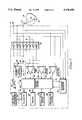
- FIG. 1is a functional block diagram of a single-chamber embodiment of an automatic implantable pulse generator, illustrating the basic elements of an automatic implantable pulse generator;
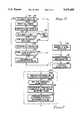
- FIG. 2is a flow chart describing an overview of the operation of the preferred embodiment, a dual-chamber, automatic implantable pulse generator, configured in accordance with the teachings of the present invention
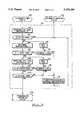
- FIG. 3is a detailed flow chart describing the step of "detecting a ventricular lead in contact with body tissue," shown in FIG. 2;
- FIG. 4is a detailed flow chart describing the step of "detecting an atrial lead in contact with body tissue," shown in FIG. 2;
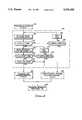
- FIG. 5is a flow chart describing the preferred embodiment of the step of "programming the automatic features ON,” shown in FIG. 2, which includes, but is not limited to, programming automatic sensitivity, automatic capture, rate response, and automatic electrode configuration modes ON;
- FIG. 6is a flow chart describing the operation of the preferred sequence of steps for the automatic sensitivity and automatic capture modes shown in FIG. 5;
- FIG. 7is a flow chart describing the operation of the rate-response mode with the automatic adjustment of rate-response parameters.
- FIG. 1a simplified block diagram of a single-chamber embodiment of an automatic implantable pulse generator is shown.
- a single-chamber pulse generator 10is illustrated coupled to a heart 12 by way of a lead 14.
- the lead 14is shown as a bipolar lead (i.e., having a tip electrode 16 and a ring electrode 18) because of the many benefits of bipolar leads. For example, capture detection, which is one of the desired automatic features of the preferred embodiment, is superior when used with bipolar electrodes.
- bipolar stimulationcan eliminate pectoral stimulation; bipolar sensing can eliminate sensing of noise and EMI; and further, if a wire fractures, automatic electrode configuration (described in more detail below) can reprogram the electrode configuration to an alternative pair of operable electrodes. While a single-chamber, bipolar system is shown, this is only to illustrate the basic functional blocks. It is understood that one skilled in the art could adapt the present invention to be used in either a dual-chamber device or with unipolar leads.
- Controlling the single-chamber pulse generator 10is a processor control system 20.
- the processor control system 20could be constructed from dedicated logic and timing circuitry, state machine circuitry, or a microprocessor.
- Output pulse circuitry 22generates stimulation pulses to the tip electrode 16 through the lead 14.
- the output pulse circuitry 22is coupled to a battery 24 which charges a capacitor 26 to a desired or programmed value. When the capacitor 26 is fully charged, the charge is delivered to the heart 12 through an output capacitor 28.
- the ventricular output pulseis referred to as the "V-pulse.”
- the processor control system 20generates trigger signals to the output pulse circuitry 22 over signal line 36 to control both the rate and the inhibition of the stimulation pulses.
- a switch bank 30determines the polarity of the stimulation pulses, e.g., unipolar or bipolar, by selectively closing the appropriate switches.
- a sense amplifier 32is coupled to the lead 14 through the switch bank 30 and detects the presence of cardiac activity.
- the sense amplifier 32is connected to the processor control system 20 which will inhibit the output pulse circuitry 22 whenever cardiac activity is sensed, in a demand fashion.
- the sense amplifier 32receives control signals over signal line 40 from the processor control system 20. These control signals include controlling the gain (sensitivity) and the timing of any blocking circuitry (not shown) coupled to the inputs of the sense amplifier 32.
- the switch bank 30likewise controls the polarity of the sense amplifier 32 in one of three sensing configurations, i.e., tip-ring, tip-case or ring-case.
- the switch bank 30receives a control signal 34 from the processor control system 20 which enables the appropriate combination of switches, S1-S8, to turn ON or OFF.
- Switches S1 and S2connect either a case electrode 38 or the ring electrode 18, respectively, to the positive terminal of capacitor 26, thus enabling either the case 38 or ring electrode 18 to act as the return electrode for the output pulse circuitry 22.
- Switch S4connects the tip electrode 16 to the negative terminal of the capacitor 26, thus acting as the cathode or stimulating electrode.
- Switch S3could be used to connect the ring electrode as the stimulating electrode (typically, the ring is used for stimulation only if the tip electrode is defective).
- the physicianmay program the stimulation pulses (via an external programmer 52) to be either tip-ring, tip-case or ring-case.
- the processor control system 20would close switches S4 and S2 for tip-ring pacing; switches S4 and S1 for tip-case pacing; and switches S3 and S1 for ring-case pacing.
- the physicianmay also program the polarity of the sense amplifiers, independent of the stimulation polarity.
- the processor control system 20would close switches S5 and S7 for tip-ring sensing; switches S5 and S8 for tip-case sensing; and switches S6 and S8 for ring-case sensing.
- the processor control system 20also controls the rate at which the output pulse circuitry 22 generates stimulation pulses, as well as keeping track of the timing of any refractory period, PVARP intervals, noise detection windows, alert intervals, etc., as is known in the art.
- the processor control system 20is connected to a memory circuit 42 by a suitable data/address bus 44.
- This memory circuit 42allows certain control parameters, used by the processor control system 20 in controlling the operation of the pulse generator 10, to be programmably stored and modified, as required, in order to customize the operation of the pulse generator 10 to suit the needs of a particular patient. Further, data sensed during the operation of the pulse generator 10 may be stored in the memory circuit 42 for later retrieval and analysis.
- a telemetry circuit 46is further included in the pulse generator 10.
- This telemetry circuit 46is connected to the processor control system 20 by way of a suitable command/data bus 50.
- the telemetry circuit 46may be selectively coupled to an external programming device 52 by means of an appropriate communication link 54, which may be any suitable electromagnetic link, such as an RF (radio frequency) link.
- desired commandsmay be sent to the processor control system 20 and data (either held within the processor control system 20, as in a data latch, or stored within the memory circuit 42,) may be remotely received from the pulse generator 10. In this manner, noninvasive communications may be established with the implanted pulse generator 10 from a remote, non-implanted location.
- the pulse generator 10includes a physiologic sensor 56. While the physiologic sensor 56 is illustrated in FIG. 1 as being included within the pulse generator 10, it is to be understood that the physiologic sensor 56 may also be external to the pulse generator 10, yet still be implanted within or carried by the patient.
- the physiological sensor 56is used to detect the exercise state of the patient, to which the processor control system 20 responds by adjusting the rate at which the output pulse circuitry 22 generates stimulation pulses.
- Such sensorsare commonly called “rate-responsive" sensors.
- a common type of rate-responsive sensoris an activity sensor, such as a piezoelectric crystal, which is mounted to the can or case of the pulse generator 10.
- physiologic sensorssuch as sensors which sense the oxygen content of blood, respiration rate, pH of blood, body motion, and the like.
- the type of sensor usedis not critical to the present invention. Any sensor which is capable of sensing some physiological parameter which is relatable to the rate at which the heart should be beating may be used.
- the present inventionemploys automatic capture detection. As illustrated in FIG. 1, this may be performed by a capture detector 62.
- the capture detector 62detects a depolarization signal during a window following a stimulation pulse, the presence of which indicates capture has occurred. It is also known in the art to use the sense amplifier 32 to perform this function. Capture detection may occur on a beat-by-beat basis or on a sampled basis.
- a capture threshold searchis performed once a day during at least the acute phase (e.g., the first 30 days) and less frequently thereafter. A capture threshold search would begin at a desired starting point (either a high energy level or the level at which capture is currently occurring) and decrease the energy level until capture is lost.
- the value at which capture is lostis known as the capture threshold. Thereafter, a safety margin is added to the capture threshold.
- the value of the safety marginwould depend on whether capture detection is to be performed on a beat-by-beat basis or only sampled. For example, capture detection performed on a beat-by-beat basis could have a safety margin just slightly above threshold, whereas capture every 4 or 8 beats would require a slightly larger safety margin to ensure that capture is not lost in between verification times.
- capture detection circuitry and algorithmsare well known. See for example, U.S. Pat. No. 4,729,376 (Decote, Jr.); U.S. Pat. No. 4,708,142 (Decote, Jr.); U.S. Pat. No. 4,686,988 (Sholder); and U.S. Pat. No. 4,969,467 (Callaghan et al.), which patents are hereby incorporated herein by reference.
- the type of capture detection system usedis not critical to the present invention. Any system which is capable of detecting capture may be used.
- the present inventionfurther employs automatic sensitivity adjustment circuitry 64.
- FIG. 1it is depicted as an amplifier coupled to corresponding inputs of the sense amplifier 32.
- the automatic sensitivity adjustment circuitry 64receives control signals over signal line 66 from the processor control system 20 and has an output 68 which is coupled to the processor control system 20. Based on the output of the automatic sensitivity adjustment circuitry 64, the processor control system 20 can adjust the sensitivity of the sense amplifier 32.
- the type of automatic sensitivity adjustment system usedis not critical to the present invention. Any system which is capable of automatically adjusting the sensitivity may be used.
- the automatic sensitivity adjustment circuitry 64could comprise a second sense amplifier having a slightly lower sensitivity threshold than the sense amplifier 32.
- the sensitivities of both amplifiersmay be adjusted until one amplifier senses when the other does not.
- the automatic sensitivity adjustment circuitry 64could employ a peak detector as describe in U.S. Pat. No. 4,708,144 (Hamilton et al.), which is also incorporated herein by reference.
- the present inventionalso preferably employs a system for automatically configuring the electrode polarity to an operable pair of electrodes.
- an impedance detector 70is directly coupled to the lead 14 and to the case electrode 38.
- the processor control system 20provides control signals over signal line 72 to direct the impedance detector 70 which pair of electrodes to take a measurement between. This technique is well known in the art for detecting lead failures.
- the processor control system 20can determine an operable electrode configuration and adjust the switch bank 30 to deliver stimulation pulses and sense cardiac signals between the operable pair of electrodes.
- the present inventionis directed toward a system for detecting that a pulse generator and an implantable lead are implanted so that all of the automatic features can be automatically turned ON. Without this invention, automatic features must be shipped in their OFF state and programmed ON by the physician, otherwise they would be endlessly stuck searching for capture thresholds, sensitivity signals, measurements, rate thresholds, etc.
- the preferred embodimentfurther employs redundant methods of detecting that a pulse generator and an implantable lead are implanted.
- the impedance detector 70coupled with the processor control system 20, is used to detect that the lead 14 is in contact with the body by determining if the lead impedance is within a prescribed range. When the measured impedance is within, for example, 100 to 2000 ohms, then the processor control system 20 assumes that a lead has been implanted and properly connected to the pulse generator 10.
- a temperature sensor 80is used as a redundant method of detecting that the pulse generator 10 and/or the lead (depending on the location of the temperature sensor 80) has been implanted. For example, a thermistor located inside the pulse generator or on the lead could quickly detect body temperature and confirm that the lead and/or pulse generator has been implanted.
- a shorting plug(not shown) could be inserted into the output channel of a pulse generator's connector top (not shown), i.e., across the tip and ring terminals.
- An impedance measurement by the impedance detector 70can be used to detect the presence of the shorting plug. When the physician removes the shorting plug at implant, the impedance detector 70 will detect the absence of the shorting plug (i.e., an open circuit) until such time that the pulse generator 10 is connected to an implanted lead.
- the impedance detector 70will assume that the pulse generator has not been implanted if it consistently detects a precisely known value of a resistive load.
- FIG. 2a flow chart describing an overview of the operation of the automatic implantable pulse generator of the present invention is shown.
- this flow chartand the other flow charts described herein, the various steps are summarized in individual “blocks” or boxes. Such blocks describe specific actions or decisions that must be made or carried out as the algorithm proceeds. Specific circuitry that carries out these steps can readily be fashioned by those skilled in the art.
- the flow charts presented hereinprovide the basis for a "control program” that may be used by such microprocessor, or equivalent, to effectuate the desired control of the pulse generator.
- Those skilled in the artsmay readily write such a control program based on the flow charts and other descriptions presented herein.
- the flow chartbegins with an arrow 100.
- This arrow 100schematically represents that the flow chart of FIG. 2 forms a portion of an overall control program associated with the process control system 20.
- the pulse generatoris a bipolar, dual-chamber device.
- the single-chamber pulse generator shown in FIG. 1could easily adapt to include a second channel coupled to a lead in the atrium by simply duplicating the associated components shown for the ventricular lead.
- One skilled in the artcould also easily adapt the flow charts shown in FIGS. 2-6 to use only a single-chamber device.
- the pulse generatormay be programmed by the manufacturer to be automatic or manual. Thus, a test is performed, at block 102, to detect if the automatic mode has been programmed ON. If it is OFF, then the present invention is bypassed and pulse generator returns to normal pacing functions (block 156). If the automatic mode is programmed ON, then all of the timers are reset (block 103) and the pulse generator goes into a sleep, or storage, mode (block 104) in which high current drain functions are disabled, e.g., turning OFF the output pulse circuitry 22, the sense amplifier(s) 32, and reducing the duty cycle of the processor control means 20.
- a testis performed, at block 102, to detect if the automatic mode has been programmed ON. If it is OFF, then the present invention is bypassed and pulse generator returns to normal pacing functions (block 156). If the automatic mode is programmed ON, then all of the timers are reset (block 103) and the pulse generator goes into a sleep, or storage, mode (block 104) in which high
- all three methods of detecting if the pulse generator has been implantedare included: using the shorting plug; using the temperature sensor 80; and using the impedance detector 70. Although it is recognized that any single method could be used, it is preferred to have at least a combination of two sensors.
- the first stepis to detect the absence or presence of the shorting plug.
- a ventricular lead impedance, Z1is measured (block 112) across the ventricular tip and ring electrode using the impedance detector 70 (shown in FIG. 1). If a ventricular shorting plug has not been removed (indicating that the pulse generator is still in its sterile package), then the lead impedance will be essentially zero (block 114). Thus, the program will return to the beginning of the routine (block 102, FIGS. 2 and 3) and go back to the sleep mode until the next wakeup. If, on the other hand, the ventricular shorting plug has been removed, then the lead impedance will be greater than 25 ohms (actually, it will be an open circuit until such time that the lead is implanted and connected to the pulse generator).
- the successful detection of the removal of the shorting plug(at block 114) will initiate a temperature measurement (block 116) and a determination of whether the temperature is body temperature (test 118), thus confirming that the device has been implanted.
- the time interval, xis selected to allow the physician sufficient time to implant the lead/pulse generator, while still indicating a problem if the proper temperature is not found within a reasonable time. This is achieved using a second timer, Timer2, to determine if "x" seconds have elapsed (block 119). If Timer2 is less than "x" seconds, the pulse generator will wait 1 second (block 120) and then repeat the measurement (block 116). If Timer2 is greater than "x" seconds, then the physician will be alerted (block 132) of a malfunction, either by sounding an audible alarm (not shown) or by telemetry back to the external programmer.
- a ventricular lead impedance, Z2is measured (block 122) across the ventricular tip and ring electrode. If the lead impedance, Z2, is still greater than 2000 ohms (block 124), one of two things could be happening: (1) the lead has not yet been connected to the pulse generator or (2) the lead has a broken conductor.
- the systemwill either repeat the measurement after a short delay or exit the program after "y" seconds have elapsed, thereby indicating a malfunction.
- the time interval, yis selected to allow the physician sufficient time to connect the lead to the pulse generator, while still indicating a problem if the proper lead impedance is not found within a reasonable time. This is achieved using a third timer, Timer3, to determine if "y" seconds have elapsed (block 126) . If Timer3 is less than "y" seconds, the pulse generator will wait 1 second (block 128) and then repeat the measurement (block 122).
- Timer3is greater than "y" seconds, indicating that there may be a conductor failure, then the physician will be alerted (block 132) of a malfunction, either by sounding an audible alarm (not shown) or by telemetry back to the external programmer. Thus, the program will return to the beginning of the routine (block 102, FIGS. 2 and 3) and go back to the sleep mode until the next wakeup. If, on the other hand, the lead impedance, Z2, is less than 2000 ohms (indicating that the lead has been connected to the pulse generator), then a determination is made (block 130) to ensure that the lead is not shorted or abnormally low.
- the range for normal lead impedances for a "good" leadmay vary between 250 and 900 ohms, depending on the electrode size, materials, and polarity selected (unipolar or bipolar).
- the criteria of 100 to 2000 ohmshas been chosen to encompass even poor leads which are still in patients and were designed with older technology.
- the lead impedance, Z2is within the range of 100 to 2000 ohms, and if the temperature is at body temperature and the ventricular shorting plug is removed, then there is a high degree of confidence that the lead and pulse generator are implanted, i.e., the pulse generator has been removed from its sterile package and prepared for implantation, physically placed in the body, and properly connected to a lead which is in good electrical contact with body tissue.
- the pulse generatorwill program single-chamber VVI pacing ON (block 134, FIGS. 2, 3 and 4).
- a testis performed to determine if an atrial lead has been implanted (block 135, FIG. 2). As is shown in more complete detail in FIG. 4, an atrial lead impedance, Z3, is measured (block 136) across an atrial tip and ring electrode using the lead impedance detector 70 (shown in FIG. 1).
- the lead impedance detectedwill be essentially zero (block 137). Thereafter, the system will either repeat the measurement after a short delay or exit the program after "p" minutes have elapsed, thereby indicating a malfunction.
- the time interval, pis selected to allow the physician sufficient time to connect the atrial lead to the pulse generator, while still indicating a problem if the proper lead impedance is not found within a reasonable time.
- a fourth timer, Timer4determines if "p" minutes have elapsed (block 138). If Timer4 is less than "p" minutes, the pulse generator will wait 1 second (block 140) and then repeat the measurement (block 136).
- Timer4is greater than "p" minutes, indicating that there may be a conductor failure or the plug has not been removed, then the physician will be alerted (block 152, FIGS. 2 and 4) of a malfunction (either by sounding an audible alarm or via telemetry) and the atrial channel would be disabled. If, on the other hand, the shorting plug has been removed, then the lead impedance will be greater than 25 ohms at block 137 (actually, it will be an open circuit until such time that the atrial lead is implanted and connected to the pulse generator).
- an atrial lead impedance, Z4is measured (block 142) across the atrial tip and ring electrode. If the atrial lead impedance, Z4, is still greater than 2000 ohms (block 144), one of two things could be happening: (1) the atrial lead has not yet been connected to the pulse generator or (2) the atrial lead has a broken conductor.
- Timer5determines if "q" minutes have elapsed (block 146). If Timer5 is less than "q” minutes, the pulse generator will wait 1 second (block 147) and then repeat the measurement (block 142). If Timer5 is greater than "q" minutes, indicating that there may be a conductor failure, then the physician will be alerted (block 152, FIGS. 2 and 4) of a malfunction and the atrial channel would be disabled (i.e., only single-chamber VVI pacing will be enabled).
- the atrial lead impedance, Z4is less than 2000 ohms (indicating that the lead has been properly connected to the pulse generator)
- the automatic featureswould then be programmed ON (block 154, FIGS. 2, 4 and 5) for only the operative lead(s), i.e., the lead(s) having an impedance in the expected range of impedances.
- FIG. 5the preferred sequence of programming automatic features ON (block 154, FIG. 2) is shown.
- autosensitivity featureswould be enabled first (block 200), followed by autocapture (block 250), rate-response mode (block 300), autoelectrode configuration (block 350), and any other programmable features (block 400).
- the step of programming autosensitivity mode ONwould consist of initiating a sensitivity threshold test (block 204), determining if a threshold value was found (block 206), and automatically programming the sense amplifier 32 to one of a plurality of sensitivities based on the threshold value plus a safety margin (block 208). This process would be repeated for each channel (not shown).
- the step of programming autocapture mode 0Nwould consist of increasing the pacing rate above the intrinsic rate (block 253), initiating a capture threshold test (block 254), determining if a threshold value was found (block 256), automatically programming the pulse generator to one of a plurality of energy levels based on the threshold value plus a safety margin (block 258), and reprogramming the pacing rate back to the Base Rate (block 260). This process would also be repeated for each channel (also not shown).
- the step of programming the automatic adjustment of rate (i.e., rate-response mode) ONwould consist of initiating a rate-response threshold test (block 304), determining if a threshold value was found (block 306), programming the pulse generator to a value corresponding to the threshold value plus an offset value (block 308), and programming other automatically adjustable rate-responsive parameters (block 310).
- rate-response threshold testblock 304
- determining if a threshold value was foundblock 306
- programming the pulse generator to a value corresponding to the threshold value plus an offset valueblock 308
- other automatically adjustable rate-responsive parametersblock 310.
- automatically adjustable rate-responsive parameterssee U.S. Pat. Nos. 4,940,053 (Mann et. al); 4,940,052 (Mann et. al); and 5,024,222 (Thacker); and U.S. patent application Ser. Nos. 07/844,818 and 07/844,807, all of which are assigned to the
- the automatic electrode configuration routine(described above and already incorporated by reference) could be programmed ON to ensure the long term reliability of the pacing system.
- any other automatic featuresuch as automatic A-V delay adjustment, automatic blanking window adjustment, automatic refractory period adjustment, etc. could be invoked.
- the advantages of the present inventionresult in a fully automatic implantable pulse generator which can adapt itself to the prevailing needs of the patient, can considerably simplify the programming of the device at implant, while providing the maximum current drain savings during its shelf life.
- the present inventionprovides a higher quality of life for the patient, making the method of the present invention a highly desirable enhancement to implantable cardiac pulse generator therapy.
Landscapes
- Health & Medical Sciences (AREA)
- Heart & Thoracic Surgery (AREA)
- Life Sciences & Earth Sciences (AREA)
- Cardiology (AREA)
- Public Health (AREA)
- Engineering & Computer Science (AREA)
- Biomedical Technology (AREA)
- Nuclear Medicine, Radiotherapy & Molecular Imaging (AREA)
- Radiology & Medical Imaging (AREA)
- Animal Behavior & Ethology (AREA)
- General Health & Medical Sciences (AREA)
- Veterinary Medicine (AREA)
- Biophysics (AREA)
- Physiology (AREA)
- Neurology (AREA)
- Neurosurgery (AREA)
- Electrotherapy Devices (AREA)
Abstract
Description
The present invention relates in general to implantable medical devices, and more specifically, to implantable cardiac stimulation devices which can automatically wake up when implanted and, once activated, automatically determine various parameters normally determined by the physician at implant, e.g., modes, capture and sensing thresholds.
The technology of cardiac stimulation devices has developed into a high level of sophistication with respect to system performance. The current generation of cardiac pulse generators, or pacemakers, incorporate microprocessors and related circuitry to sense and stimulate heart activity under a variety of physiological conditions. Cardiac pulse generators may also be of the type which include arrhythmia detection and may be programmed to control the heart in correcting or compensating for various heart abnormalities, e.g., antitachycardia pacemakers, cardioverters and defibrillators. A background description of modern cardiac pacemaker technology is set forth in U.S. Pat. No. 4,712,555, which patent is incorporated herein by reference.
As the complexity of cardiac pulse generators increases, the physician is faced with numerous programmable parameters to set and measurements to take at implant. It is because of this complexity that many physicians implant the pulse generators without ever reprogramming them. As a result, the manufacturer becomes the "implanting physician" by selecting "as shipped" values that are also considered safe for implanting. For example, a single-chamber VVI pulse generator is typically shipped by the manufacturer at a rate of 70 ppm, a ventricular output of 4 volts and 0.6 ms, and a ventricular sensitivity of 2 mV. If the pulse generator is shipped in the dual-chamber mode, the pulse generator will additionally include an atrial output of 4 volts and 0.6 ms, and an atrial sensitivity of 1 mV. Some manufacturers have elected to ship their dual-chamber DDD pacemakers in a VVI mode. If the physician never reprograms the latter devices to DDD mode or changes the output amplitude to conserve current drain, both the patient's health and the performance of the pulse generator are compromised.
Automatic features have been taught in several patents and incorporated into several manufacturer's devices. For example, "automatic output regulation" or "automatic capture detection" techniques typically include: automatically adjusting the energy of the applied pacing pulses according to a prearranged routine until capture is obtained; periodically testing the threshold (particularly during the acute phase); and verifying capture on a beat-by-beat basis, providing high amplitude backup pulses when capture is lost. See, for example, U.S. Pat. No. 4,729,376 (Decote, Jr.); U.S. Pat. No. 4,708,142 (Decote, Jr.); U.S. Pat. No. 4,686,988 (Sholder); and U.S. Pat. No. 4,969,467 (Callaghan et al.).
Autosensitivity features are also well known. For example, in U.S. Pat. No. 4,768,511 (Decote Jr.), the thresholds of the two voltage comparators are automatically adjusted so that one of the voltage comparators will sense the cardiac activity of the selected heart chamber and the other voltage comparator will not sense the cardiac activity. A similar arrangement is taught in U.S. Pat. No. 4,766,902 (Schroeppel). In U.S. Pat. No. 5,050,599 (Hoegnelid) two detectors are also used with a setting means which sets the sensitivity of the first detector such that the first detector means detects every event detected by the second detector, however, the second detector senses impedance which corresponds to an electrical cardiac signal while the first detector detects electrical cardiac signals. In U.S. Pat. No. 4,708,144 (Hamilton et al.), sensitivity is automatically controlled by measuring the peak value of each R-wave, and deriving a long-term average value. The gain of the sense channel is then adjusted according to the average of the measured peak values.
In U.S. Pat. No. 5,003,975 (Duncan et al.), an "Automatic Electrode Configuration Of An Implantable Pacemaker" is shown in which lead impedance is automatically measured to determine a functioning electrode configuration (unipolar, bipolar or unipolar from the ring). If a proper impedance measurement is not sensed for the programmed configuration, additional impedance measurements for other possible configurations are made in an ordered sequence in order to determine if an improper lead has been implanted or if an electrode has broken. When an operable configuration is found, the pacemaker continues operation in that configuration, thereby ensuring that capture can continue to occur until such time as the problem which has been detected can be corrected.
Another "automatic" feature is the "rate adaptive" or "rate-responsive" mode found in some pulse generators. Once this mode is enabled the pulse generator will automatically adjust the rate according to the patient's physiological needs, e.g., emotional and/or exercise demand.
A disadvantage of all of these "automatic" features is that they must be turned ON after implanting the device. They cannot be included in the "as shipped values" because in each case the device would be endlessly searching for a desired result or disable themselves. For example, a pulse generator in an autocapture mode would endlessly search for capture and/or perform a threshold search and/or disable itself when none was found. Likewise, the autosensitivity mode would endlessly look for cardiac signals that it could calibrate to. The automatic electrode configuration mode would never find an impedance to determine the "best" electrode to program to. The rate adaptive mode would be adjusting the rate according to the selected sensor (e.g., motion, temperature, etc.). Shelf-life is significantly affected by the dynamic current drain caused by the microprocessor constantly waking up to perform unnecessary pacemaker operations. Thus, it should be apparent that the current drain would be too excessive to permit shipping in these "automatic" modes.
What is needed is a pulse generator which will automatically turn itself ON at implant and automatically set itself to operate at safe thresholds for the patient, to initiate other "automatic" features," while still conserving power consumption, particularly during the "shelf-life" of the pulse generator. The present invention addresses these and other needs.
The present invention is directed toward a system for detecting that a pulse generator and an implantable lead are properly implanted so that a plurality of automatic features can be automatically turned ON. Thus, the present invention is directed towards a "fully automatic" and "intelligent" pulse generator.
In the preferred embodiment, an impedance detector is used to detect that the electrodes are in contact with the body by determining if the lead impedance is within a prescribed range, for example, between 100 to 2000 ohms. The preferred embodiment also employs redundant methods of detecting that a pulse generator and an implantable lead are implanted. For example, a temperature sensor may be used to quickly detect body temperature and confirm that the lead and/or pulse generator has been implanted. As an alternative redundant sensor or as a second confirming sensor, a shorting plug (or a resistive load) could be inserted into the output channel of a pulse generator. An impedance measurement by the impedance detector can be used to detect the presence or removal of the shorting plug.
In the preferred embodiment, at least two sensors are used to reliably detect that the pulse generator has been properly connected to an implanted lead. The precise two sensors employed would depend to a large extent on the features currently in a manufacturer's product. For example, temperature sensors are well known in the art for rate-responsive purposes. Such a device may select the combination of lead impedance and temperature to detect that the lead/pulse generator has been implanted. Other manufacturers may already be shipping their devices with a resistive load (so that they may verify that the lead impedance feature is functional after sterilization). These latter devices may opt to detect the resistive load, followed by a proper tissue-electrode lead impedance.
Thus, the advantages of the present system include: saving current consumption during the pulse generator's shelf life (thereby prolonging battery life); and providing a pulse generator which can automatically determine appropriate operating parameters, both at implant and during the life of the pulse generator. In theory, the system would not need a programmer system and could simply be verified for proper functionality by using an ECG recorder. In the extreme case, where the physician does not have a programmer or an ECG recorder, the present invention could alert the physician of a malfunction by sounding an audible alarm.
Further features and advantages of the present invention may be more readily understood by reference to the following description taken in conjunction with the accompanying drawings, in which:
FIG. 1 is a functional block diagram of a single-chamber embodiment of an automatic implantable pulse generator, illustrating the basic elements of an automatic implantable pulse generator;
FIG. 2 is a flow chart describing an overview of the operation of the preferred embodiment, a dual-chamber, automatic implantable pulse generator, configured in accordance with the teachings of the present invention;
FIG. 3 is a detailed flow chart describing the step of "detecting a ventricular lead in contact with body tissue," shown in FIG. 2;
FIG. 4 is a detailed flow chart describing the step of "detecting an atrial lead in contact with body tissue," shown in FIG. 2;
FIG. 5 is a flow chart describing the preferred embodiment of the step of "programming the automatic features ON," shown in FIG. 2, which includes, but is not limited to, programming automatic sensitivity, automatic capture, rate response, and automatic electrode configuration modes ON;
FIG. 6 is a flow chart describing the operation of the preferred sequence of steps for the automatic sensitivity and automatic capture modes shown in FIG. 5; and
FIG. 7 is a flow chart describing the operation of the rate-response mode with the automatic adjustment of rate-response parameters.
The following description is of the best mode presently contemplated for practicing the invention. This description is not to be taken in a limiting sense but is made merely for the purpose of describing the general principles of the invention. The scope of the invention should be ascertained with reference to the issued claims. In the description of the invention that follows, like numerals or reference designators will be used to refer to like parts or elements throughout.
In FIG. 1, a simplified block diagram of a single-chamber embodiment of an automatic implantable pulse generator is shown. A single-chamber pulse generator 10 is illustrated coupled to aheart 12 by way of alead 14. Thelead 14 is shown as a bipolar lead (i.e., having atip electrode 16 and a ring electrode 18) because of the many benefits of bipolar leads. For example, capture detection, which is one of the desired automatic features of the preferred embodiment, is superior when used with bipolar electrodes. Also, it is well known that bipolar stimulation can eliminate pectoral stimulation; bipolar sensing can eliminate sensing of noise and EMI; and further, if a wire fractures, automatic electrode configuration (described in more detail below) can reprogram the electrode configuration to an alternative pair of operable electrodes. While a single-chamber, bipolar system is shown, this is only to illustrate the basic functional blocks. It is understood that one skilled in the art could adapt the present invention to be used in either a dual-chamber device or with unipolar leads.
Controlling the single-chamber pulse generator 10 is aprocessor control system 20. As is well known in the art, theprocessor control system 20 could be constructed from dedicated logic and timing circuitry, state machine circuitry, or a microprocessor.
Asense amplifier 32 is coupled to thelead 14 through theswitch bank 30 and detects the presence of cardiac activity. Thesense amplifier 32 is connected to theprocessor control system 20 which will inhibit theoutput pulse circuitry 22 whenever cardiac activity is sensed, in a demand fashion. Thesense amplifier 32 receives control signals oversignal line 40 from theprocessor control system 20. These control signals include controlling the gain (sensitivity) and the timing of any blocking circuitry (not shown) coupled to the inputs of thesense amplifier 32. Theswitch bank 30 likewise controls the polarity of thesense amplifier 32 in one of three sensing configurations, i.e., tip-ring, tip-case or ring-case.
Theswitch bank 30 receives acontrol signal 34 from theprocessor control system 20 which enables the appropriate combination of switches, S1-S8, to turn ON or OFF. Switches S1 and S2 connect either acase electrode 38 or the ring electrode 18, respectively, to the positive terminal ofcapacitor 26, thus enabling either thecase 38 or ring electrode 18 to act as the return electrode for theoutput pulse circuitry 22. Switch S4 connects thetip electrode 16 to the negative terminal of thecapacitor 26, thus acting as the cathode or stimulating electrode. Alternatively, Switch S3 could be used to connect the ring electrode as the stimulating electrode (typically, the ring is used for stimulation only if the tip electrode is defective). In this way, the physician may program the stimulation pulses (via an external programmer 52) to be either tip-ring, tip-case or ring-case. For example, theprocessor control system 20 would close switches S4 and S2 for tip-ring pacing; switches S4 and S1 for tip-case pacing; and switches S3 and S1 for ring-case pacing.
The physician may also program the polarity of the sense amplifiers, independent of the stimulation polarity. For example, theprocessor control system 20 would close switches S5 and S7 for tip-ring sensing; switches S5 and S8 for tip-case sensing; and switches S6 and S8 for ring-case sensing.
Theprocessor control system 20 also controls the rate at which theoutput pulse circuitry 22 generates stimulation pulses, as well as keeping track of the timing of any refractory period, PVARP intervals, noise detection windows, alert intervals, etc., as is known in the art.
Theprocessor control system 20 is connected to amemory circuit 42 by a suitable data/address bus 44. Thismemory circuit 42 allows certain control parameters, used by theprocessor control system 20 in controlling the operation of the pulse generator 10, to be programmably stored and modified, as required, in order to customize the operation of the pulse generator 10 to suit the needs of a particular patient. Further, data sensed during the operation of the pulse generator 10 may be stored in thememory circuit 42 for later retrieval and analysis.
Atelemetry circuit 46 is further included in the pulse generator 10. Thistelemetry circuit 46 is connected to theprocessor control system 20 by way of a suitable command/data bus 50. In turn, thetelemetry circuit 46 may be selectively coupled to anexternal programming device 52 by means of anappropriate communication link 54, which may be any suitable electromagnetic link, such as an RF (radio frequency) link. Advantageously, through theexternal programmer 52 and thecommunication link 54, desired commands may be sent to theprocessor control system 20 and data (either held within theprocessor control system 20, as in a data latch, or stored within thememory circuit 42,) may be remotely received from the pulse generator 10. In this manner, noninvasive communications may be established with the implanted pulse generator 10 from a remote, non-implanted location.
In the preferred embodiment, the pulse generator 10 includes aphysiologic sensor 56. While thephysiologic sensor 56 is illustrated in FIG. 1 as being included within the pulse generator 10, it is to be understood that thephysiologic sensor 56 may also be external to the pulse generator 10, yet still be implanted within or carried by the patient. Thephysiological sensor 56 is used to detect the exercise state of the patient, to which theprocessor control system 20 responds by adjusting the rate at which theoutput pulse circuitry 22 generates stimulation pulses. Such sensors are commonly called "rate-responsive" sensors. A common type of rate-responsive sensor is an activity sensor, such as a piezoelectric crystal, which is mounted to the can or case of the pulse generator 10. Other types of physiologic sensors are also known, such as sensors which sense the oxygen content of blood, respiration rate, pH of blood, body motion, and the like. The type of sensor used is not critical to the present invention. Any sensor which is capable of sensing some physiological parameter which is relatable to the rate at which the heart should be beating may be used.
In the preferred embodiment, the present invention employs automatic capture detection. As illustrated in FIG. 1, this may be performed by a capture detector 62. The capture detector 62 detects a depolarization signal during a window following a stimulation pulse, the presence of which indicates capture has occurred. It is also known in the art to use thesense amplifier 32 to perform this function. Capture detection may occur on a beat-by-beat basis or on a sampled basis. Preferably, a capture threshold search is performed once a day during at least the acute phase (e.g., the first 30 days) and less frequently thereafter. A capture threshold search would begin at a desired starting point (either a high energy level or the level at which capture is currently occurring) and decrease the energy level until capture is lost. The value at which capture is lost is known as the capture threshold. Thereafter, a safety margin is added to the capture threshold. The value of the safety margin would depend on whether capture detection is to be performed on a beat-by-beat basis or only sampled. For example, capture detection performed on a beat-by-beat basis could have a safety margin just slightly above threshold, whereas capture every 4 or 8 beats would require a slightly larger safety margin to ensure that capture is not lost in between verification times.
The implementation of capture detection circuitry and algorithms are well known. See for example, U.S. Pat. No. 4,729,376 (Decote, Jr.); U.S. Pat. No. 4,708,142 (Decote, Jr.); U.S. Pat. No. 4,686,988 (Sholder); and U.S. Pat. No. 4,969,467 (Callaghan et al.), which patents are hereby incorporated herein by reference. The type of capture detection system used is not critical to the present invention. Any system which is capable of detecting capture may be used.
The present invention further employs automaticsensitivity adjustment circuitry 64. In FIG. 1, it is depicted as an amplifier coupled to corresponding inputs of thesense amplifier 32. The automaticsensitivity adjustment circuitry 64 receives control signals oversignal line 66 from theprocessor control system 20 and has anoutput 68 which is coupled to theprocessor control system 20. Based on the output of the automaticsensitivity adjustment circuitry 64, theprocessor control system 20 can adjust the sensitivity of thesense amplifier 32. The type of automatic sensitivity adjustment system used is not critical to the present invention. Any system which is capable of automatically adjusting the sensitivity may be used. For example, the automaticsensitivity adjustment circuitry 64 could comprise a second sense amplifier having a slightly lower sensitivity threshold than thesense amplifier 32. Under control of theprocessor control system 20, the sensitivities of both amplifiers may be adjusted until one amplifier senses when the other does not. For a complete description of this method, see either U.S. Pat. No. 4,768,511 (Decote, Jr.) or U.S. Pat. No. 4,766,902 (Schroeppel), both of which are incorporated herein by reference. Alternatively, the automaticsensitivity adjustment circuitry 64 could employ a peak detector as describe in U.S. Pat. No. 4,708,144 (Hamilton et al.), which is also incorporated herein by reference.
The present invention also preferably employs a system for automatically configuring the electrode polarity to an operable pair of electrodes. As shown in FIG. 1, animpedance detector 70 is directly coupled to thelead 14 and to thecase electrode 38. Theprocessor control system 20 provides control signals oversignal line 72 to direct theimpedance detector 70 which pair of electrodes to take a measurement between. This technique is well known in the art for detecting lead failures. By detecting an impedance between an electrode pair, theprocessor control system 20 can determine an operable electrode configuration and adjust theswitch bank 30 to deliver stimulation pulses and sense cardiac signals between the operable pair of electrodes. A more detailed discussion of automatic electrode configuration can be found in U.S. Pat. No. 5,003,975 (Duncan et al.), which reference is incorporated herein by reference.
The present invention is directed toward a system for detecting that a pulse generator and an implantable lead are implanted so that all of the automatic features can be automatically turned ON. Without this invention, automatic features must be shipped in their OFF state and programmed ON by the physician, otherwise they would be endlessly stuck searching for capture thresholds, sensitivity signals, measurements, rate thresholds, etc.
The preferred embodiment further employs redundant methods of detecting that a pulse generator and an implantable lead are implanted. In the present invention, theimpedance detector 70, coupled with theprocessor control system 20, is used to detect that thelead 14 is in contact with the body by determining if the lead impedance is within a prescribed range. When the measured impedance is within, for example, 100 to 2000 ohms, then theprocessor control system 20 assumes that a lead has been implanted and properly connected to the pulse generator 10.
Atemperature sensor 80 is used as a redundant method of detecting that the pulse generator 10 and/or the lead (depending on the location of the temperature sensor 80) has been implanted. For example, a thermistor located inside the pulse generator or on the lead could quickly detect body temperature and confirm that the lead and/or pulse generator has been implanted.
As an alternative redundant sensor or as a second confirming sensor, a shorting plug (not shown) could be inserted into the output channel of a pulse generator's connector top (not shown), i.e., across the tip and ring terminals. An impedance measurement by theimpedance detector 70 can be used to detect the presence of the shorting plug. When the physician removes the shorting plug at implant, theimpedance detector 70 will detect the absence of the shorting plug (i.e., an open circuit) until such time that the pulse generator 10 is connected to an implanted lead. If it is desired to ship the pulse generator 10 with a resistive load (for purposes of testing the functionality of the device after sterilization), theimpedance detector 70 will assume that the pulse generator has not been implanted if it consistently detects a precisely known value of a resistive load.
Significant routines are hereinafter discussed with reference to operational flow diagrams. It will be appreciated that these flow diagrams can be implemented by a variety of specific process instructions prepared by persons skilled in the programming art and the present invention resides in the process and not the implementation.
In FIG. 2, a flow chart describing an overview of the operation of the automatic implantable pulse generator of the present invention is shown. In this flow chart, and the other flow charts described herein, the various steps are summarized in individual "blocks" or boxes. Such blocks describe specific actions or decisions that must be made or carried out as the algorithm proceeds. Specific circuitry that carries out these steps can readily be fashioned by those skilled in the art. Particularly, where a microprocessor or equivalent programmable control device is employed as a key element of the pulse generator, the flow charts presented herein provide the basis for a "control program" that may be used by such microprocessor, or equivalent, to effectuate the desired control of the pulse generator. Those skilled in the arts may readily write such a control program based on the flow charts and other descriptions presented herein.
As shown in FIG. 2, the flow chart begins with anarrow 100. Thisarrow 100 schematically represents that the flow chart of FIG. 2 forms a portion of an overall control program associated with theprocess control system 20. In the preferred embodiment, shown in FIGS. 2-6, the pulse generator is a bipolar, dual-chamber device. One of ordinary skill in the art could easily adapt the single-chamber pulse generator shown in FIG. 1 to include a second channel coupled to a lead in the atrium by simply duplicating the associated components shown for the ventricular lead. One skilled in the art could also easily adapt the flow charts shown in FIGS. 2-6 to use only a single-chamber device.
In the preferred embodiment shown in FIG. 2, the pulse generator may be programmed by the manufacturer to be automatic or manual. Thus, a test is performed, atblock 102, to detect if the automatic mode has been programmed ON. If it is OFF, then the present invention is bypassed and pulse generator returns to normal pacing functions (block 156). If the automatic mode is programmed ON, then all of the timers are reset (block 103) and the pulse generator goes into a sleep, or storage, mode (block 104) in which high current drain functions are disabled, e.g., turning OFF theoutput pulse circuitry 22, the sense amplifier(s) 32, and reducing the duty cycle of the processor control means 20.
Atblock 106, a determination is made as to whether or not it is time to test if the lead is in contact with the body (block 110). That is, timer (Timer1) is checked to see if a desired interval, "n" seconds, has elapse. If it has not, then the system waits 1 second (block 108) and retests. The time interval is chosen based on a compromise between the amount of current drain savings required and the amount of delay a physician would see before the device would turn ON. If Timer1 has timed out (block 106), then the test is performed to determine if the ventricular lead is in contact with the body (block 110). The test (block 110) is shown in more detail in FIG. 3.
In the preferred embodiment shown in FIG. 3, all three methods of detecting if the pulse generator has been implanted are included: using the shorting plug; using thetemperature sensor 80; and using theimpedance detector 70. Although it is recognized that any single method could be used, it is preferred to have at least a combination of two sensors.
As shown in FIG. 3, the first step is to detect the absence or presence of the shorting plug. A ventricular lead impedance, Z1, is measured (block 112) across the ventricular tip and ring electrode using the impedance detector 70 (shown in FIG. 1). If a ventricular shorting plug has not been removed (indicating that the pulse generator is still in its sterile package), then the lead impedance will be essentially zero (block 114). Thus, the program will return to the beginning of the routine (block 102, FIGS. 2 and 3) and go back to the sleep mode until the next wakeup. If, on the other hand, the ventricular shorting plug has been removed, then the lead impedance will be greater than 25 ohms (actually, it will be an open circuit until such time that the lead is implanted and connected to the pulse generator).
The successful detection of the removal of the shorting plug (at block 114) will initiate a temperature measurement (block 116) and a determination of whether the temperature is body temperature (test 118), thus confirming that the device has been implanted.
If the temperature sensor is not at body temperature, then the system will either repeat the measurement after a short delay or exit the program after "x" seconds have elapsed, thereby indicating a malfunction. The time interval, x, is selected to allow the physician sufficient time to implant the lead/pulse generator, while still indicating a problem if the proper temperature is not found within a reasonable time. This is achieved using a second timer, Timer2, to determine if "x" seconds have elapsed (block 119). If Timer2 is less than "x" seconds, the pulse generator will wait 1 second (block 120) and then repeat the measurement (block 116). If Timer2 is greater than "x" seconds, then the physician will be alerted (block 132) of a malfunction, either by sounding an audible alarm (not shown) or by telemetry back to the external programmer.
After a body temperature is successfully detected (block 118), a ventricular lead impedance, Z2, is measured (block 122) across the ventricular tip and ring electrode. If the lead impedance, Z2, is still greater than 2000 ohms (block 124), one of two things could be happening: (1) the lead has not yet been connected to the pulse generator or (2) the lead has a broken conductor.
If the lead impedance is not less than 2000 ohms, then the system will either repeat the measurement after a short delay or exit the program after "y" seconds have elapsed, thereby indicating a malfunction. The time interval, y, is selected to allow the physician sufficient time to connect the lead to the pulse generator, while still indicating a problem if the proper lead impedance is not found within a reasonable time. This is achieved using a third timer, Timer3, to determine if "y" seconds have elapsed (block 126) . If Timer3 is less than "y" seconds, the pulse generator will wait 1 second (block 128) and then repeat the measurement (block 122). If Timer3 is greater than "y" seconds, indicating that there may be a conductor failure, then the physician will be alerted (block 132) of a malfunction, either by sounding an audible alarm (not shown) or by telemetry back to the external programmer. Thus, the program will return to the beginning of the routine (block 102, FIGS. 2 and 3) and go back to the sleep mode until the next wakeup. If, on the other hand, the lead impedance, Z2, is less than 2000 ohms (indicating that the lead has been connected to the pulse generator), then a determination is made (block 130) to ensure that the lead is not shorted or abnormally low.
Typically, the range for normal lead impedances for a "good" lead may vary between 250 and 900 ohms, depending on the electrode size, materials, and polarity selected (unipolar or bipolar). The criteria of 100 to 2000 ohms has been chosen to encompass even poor leads which are still in patients and were designed with older technology. If the lead impedance, Z2, is within the range of 100 to 2000 ohms, and if the temperature is at body temperature and the ventricular shorting plug is removed, then there is a high degree of confidence that the lead and pulse generator are implanted, i.e., the pulse generator has been removed from its sterile package and prepared for implantation, physically placed in the body, and properly connected to a lead which is in good electrical contact with body tissue. Thus, the pulse generator will program single-chamber VVI pacing ON (block 134, FIGS. 2, 3 and 4).
Given that the preferred embodiment is a dual-chamber pulse generator, a test is performed to determine if an atrial lead has been implanted (block 135, FIG. 2). As is shown in more complete detail in FIG. 4, an atrial lead impedance, Z3, is measured (block 136) across an atrial tip and ring electrode using the lead impedance detector 70 (shown in FIG. 1).
If the atrial shorting plug has not been removed (indicating that the atrial lead has not yet been connected), then the lead impedance detected will be essentially zero (block 137). Thereafter, the system will either repeat the measurement after a short delay or exit the program after "p" minutes have elapsed, thereby indicating a malfunction. The time interval, p, is selected to allow the physician sufficient time to connect the atrial lead to the pulse generator, while still indicating a problem if the proper lead impedance is not found within a reasonable time. Thus, a fourth timer, Timer4, determines if "p" minutes have elapsed (block 138). If Timer4 is less than "p" minutes, the pulse generator will wait 1 second (block 140) and then repeat the measurement (block 136). If Timer4 is greater than "p" minutes, indicating that there may be a conductor failure or the plug has not been removed, then the physician will be alerted (block 152, FIGS. 2 and 4) of a malfunction (either by sounding an audible alarm or via telemetry) and the atrial channel would be disabled. If, on the other hand, the shorting plug has been removed, then the lead impedance will be greater than 25 ohms at block 137 (actually, it will be an open circuit until such time that the atrial lead is implanted and connected to the pulse generator).
Thereafter, an atrial lead impedance, Z4, is measured (block 142) across the atrial tip and ring electrode. If the atrial lead impedance, Z4, is still greater than 2000 ohms (block 144), one of two things could be happening: (1) the atrial lead has not yet been connected to the pulse generator or (2) the atrial lead has a broken conductor.
The system will repeat the measurement until "q" minutes have elapsed, after which time the system will exit and alert the physician of a malfunction. That is, a fifth timer, Timer5, determines if "q" minutes have elapsed (block 146). If Timer5 is less than "q" minutes, the pulse generator will wait 1 second (block 147) and then repeat the measurement (block 142). If Timer5 is greater than "q" minutes, indicating that there may be a conductor failure, then the physician will be alerted (block 152, FIGS. 2 and 4) of a malfunction and the atrial channel would be disabled (i.e., only single-chamber VVI pacing will be enabled).
If, on the other hand, the atrial lead impedance, Z4, is less than 2000 ohms (indicating that the lead has been properly connected to the pulse generator), then a determination is made (block 148) to ensure that the lead is not shorted or abnormally low. If the lead impedance, Z4, is within the range of 100 to 2000 ohms, the pulse generator will program dual-chamber pacing mode ON (block 150, FIGS. 2 and 4).
The automatic features would then be programmed ON (block 154, FIGS. 2, 4 and 5) for only the operative lead(s), i.e., the lead(s) having an impedance in the expected range of impedances.
In FIG. 5, the preferred sequence of programming automatic features ON (block 154, FIG. 2) is shown. In the preferred embodiment, autosensitivity features would be enabled first (block 200), followed by autocapture (block 250), rate-response mode (block 300), autoelectrode configuration (block 350), and any other programmable features (block 400).
As shown the detailed flow chart in FIG. 6, the step of programming autosensitivity mode ON (block 200, FIG. 5) would consist of initiating a sensitivity threshold test (block 204), determining if a threshold value was found (block 206), and automatically programming thesense amplifier 32 to one of a plurality of sensitivities based on the threshold value plus a safety margin (block 208). This process would be repeated for each channel (not shown).
As further shown in the detailed flow chart in FIG. 6, the step of programming autocapture mode 0N (block 250, FIG. 5) would consist of increasing the pacing rate above the intrinsic rate (block 253), initiating a capture threshold test (block 254), determining if a threshold value was found (block 256), automatically programming the pulse generator to one of a plurality of energy levels based on the threshold value plus a safety margin (block 258), and reprogramming the pacing rate back to the Base Rate (block 260). This process would also be repeated for each channel (also not shown).
As shown in FIG. 7, the step of programming the automatic adjustment of rate (i.e., rate-response mode) ON (block 300, FIG. 5) would consist of initiating a rate-response threshold test (block 304), determining if a threshold value was found (block 306), programming the pulse generator to a value corresponding to the threshold value plus an offset value (block 308), and programming other automatically adjustable rate-responsive parameters (block 310). For examples of automatically adjustable rate-responsive parameters, see U.S. Pat. Nos. 4,940,053 (Mann et. al); 4,940,052 (Mann et. al); and 5,024,222 (Thacker); and U.S. patent application Ser. Nos. 07/844,818 and 07/844,807, all of which are assigned to the same assignee as the present invention and are hereby incorporated herein by reference.
At block 350 (FIG. 5), the automatic electrode configuration routine (described above and already incorporated by reference) could be programmed ON to ensure the long term reliability of the pacing system. Atblock 400, any other automatic feature, such as automatic A-V delay adjustment, automatic blanking window adjustment, automatic refractory period adjustment, etc. could be invoked. These automatic features are well known in the art.
It will therefore be perceived that the advantages of the present invention result in a fully automatic implantable pulse generator which can adapt itself to the prevailing needs of the patient, can considerably simplify the programming of the device at implant, while providing the maximum current drain savings during its shelf life. Thus, the present invention provides a higher quality of life for the patient, making the method of the present invention a highly desirable enhancement to implantable cardiac pulse generator therapy.
Although an exemplary embodiment of the present invention has been shown and described, it will be apparent to those having ordinary skill in the art that a number of changes, modifications, or alterations to the invention as described herein may be made, none of which depart from the spirit of the present invention. All such changes, modifications, and alterations should therefore be seen as within the scope of the present invention.
Claims (51)
1. An automatic implantable pulse generator, the pulse generator having a pair of output terminals, comprising:
pulse generating means for generating stimulation pulses to a patient's heart through the pair of output terminals;
a biocompatible housing for housing the pulse generating means;
means for detecting when the housing has been implanted, the detecting means including means for measuring an impedance between the pair of output terminals, the detecting means further including means for determining when the impedance is within a predetermined range of impedances corresponding to normal cardiac tissue;
means for operating the pulse generating means in a storage mode when the detecting means detects that the housing has not been implanted; and
means for operating the pulse generating means in at least one automatic mode when the detecting means detects that the housing has been implanted.
2. The pulse generator recited in claim 1, wherein the range of impedances corresponding to normal cardiac tissue comprises 100-2000 ohms.
3. The pulse generator recited in claim 1, wherein the pulse generator is stored in a sterile package, the detecting means further comprises:
a redundant detecting means for verifying that the housing has been implanted.
4. The pulse generator recited in claim 3, wherein the redundant detecting means comprises:
a load connected between the pair of output terminals prior to storing the pulse generator in the sterile package, the load having a predetermined value; and
wherein the determining means determines when the impedance is outside a range of impedances corresponding to the predetermined value of the load, thereby indicating that the housing has been removed from the sterile package and a physician has removed the load in preparation for implantation.
5. The pulse generator recited in claim 4, wherein:
the load comprises a shorting plug connected between the pair of terminals; and
the predetermined resistive value corresponds to a short.
6. The pulse generator recited in claim 4, wherein:
the load comprises a resistive load connected between the pair of terminals; and
wherein the predetermined range corresponds to the value of the resistive load.
7. The pulse generator recited in claim 3, wherein the redundant detecting means comprises:
means for sensing temperature; and
means for determining when the temperature sensing means detects a temperature within a predetermined range corresponding to body temperature, thereby indicating that the housing is in contact with the body.
8. The pulse generator recited in claim 7, wherein the sensing means comprises a thermistor located in the implanted lead.
9. The pulse generator recited in claim 7, wherein the sensing means comprises a thermistor located in the housing.
10. The pulse generator recited in claim 1, wherein the detecting means comprises at least two detecting means.
11. The pulse generator recited in claim 10, wherein the at least two detecting means are selected from the group of detecting means comprising:
means for detecting that the pulse generating means has been properly connected to an implanted lead in contact with body tissue;
means for detecting that the housing has been prepared for implantation;
means for detecting that the housing is in physical contact with the body; and
means for detecting that an implantable lead is in physical contact with the body.
12. The pulse generator recited in claim 1, wherein the means for operating the pulse generating means in a storage mode comprises:
means for disabling a desired number of pacing functions; and
means for periodically triggering the detecting means to detect if the pulse generating means has been properly connected to an implantable lead in contact with body tissue.
13. The pulse generator recited in claim 12, further comprising:
means for sensing cardiac signals;
wherein the disabling means comprises means for disabling the pulse generating means and the sensing means.
14. The pulse generator recited in claim 12, further comprising:
processing means for controlling a plurality of modes of operations for the pulse generating means; and
wherein the disabling means comprises means for reducing the duty cycle of the processor means.
15. The pulse generator recited in claim 1, wherein:
the pulse generating means includes means for operating in a rate responsive mode, the rate responsive mode being defined by a plurality of rate responsive parameters;
the means for operating the pulse generating means in at least one automatic mode comprises means for automatically determining the plurality of rate responsive parameters so that the pulse generator may operate in the rate-responsive mode.
16. The pulse generator recited in claim 15, wherein the means for operating in the rate-responsive mode comprises:
timing means for generating stimulation pulses at a desired rate;
a physiological sensor for sensing physiological need;
means for measuring the value of the physiological sensor periodically over a predetermined period;
means for automatically determining a plurality of operating parameters based on the value of the physiological sensor measured over the predetermined period;
means for programming the plurality of operating parameters into the pulse generating means; and
means for automatically adjusting at least the rate of stimulation pulses according to the sensed physiological need.
17. The pulse generator recited in claim 1, wherein the means for operating the pulse generating means in at least one automatic mode comprises means for operating in an automatic sensitivity mode.
18. The pulse generator recited in claim 17, wherein the means for operating in the automatic sensitivity mode comprises:
sensing means for sensing cardiac signals, the sensing means having a plurality of sensitivity settings;
means for periodically detecting sensitivity threshold; and
means for automatically adjusting the sensing means to one of the plurality of sensitivity settings based on the detected sensitivity threshold.
19. The pulse generator recited in claim 1, wherein the means for operating the pulse generating means in at least one automatic mode comprises means for operating in an automatic capture mode.
20. The pulse generator recited in claim 19, wherein the means for operating in the automatic capture mode comprises:
means for generating stimulation pulses at a desired energy level;
means for detecting capture following a stimulation pulse generated by the generating means;
means for periodically detecting capture at the lowest energy level; and
means for programming the energy level of the stimulation pulse based on the detected capture threshold.
21. The pulse generator recited in claim 1, wherein the means for operating the pulse generating means in at least one automatic mode comprises means for operating in an automatic electrode configuration mode.
22. The pulse generator recited in claim 21, wherein the pulse generating means is connected to an implantable lead having a tip, a ring, wherein the housing acts as a case electrode, wherein the means for operating in the automatic electrode configuration mode comprises:
means for detecting an operable pair of electrodes in contact with body tissue; and
means for automatically programming an electrode configuration for the pulse generator to the operative pair of electrodes.
23. The pulse generator recited in claim 22, wherein the means for detecting an operable pair of electrodes in contact with body tissue comprises:
means for measuring impedance between a pair of electrodes; and
means for determining when the impedance is within a predetermined range corresponding to normal cardiac tissue.
24. The pulse generator recited in claim 1, wherein the pulse generating means includes sensing means for sensing cardiac activity, and wherein the means for operating the pulse generating means in at least one automatic mode comprises:
means for programming the sensing means in an automatic sensitivity mode; and
means for programming the pulse generating means in an automatic capture mode.
25. The pulse generator recited in claim 24, wherein the sensing means has a plurality of sensitivity settings, further comprising:
means for programming a sensitivity threshold test to determine the optimum sensitivity setting for the sensing means;
means for programming a capture threshold test to determine an optimum output pulse value for the pulse generator;
means for programming the sensing means to the optimum sensitivity setting; and
means for programming the pulse generator to optimum output pulse value.
26. An automatic implantable pulse generator, comprising:
pulse generating means for generating stimulation pulses to a patient's heart;
a biocompatible housing for housing the pulse generating means;
means for operating the pulse generating means in a plurality of automatic modes;
means for detecting when the housing has been implanted; and
means for programming the mode of operation to a low current drain mode when the detecting means detects that the housing has not been implanted, and for programming the mode of operation to at least one of the plurality of automatic modes when the detecting means detects that the housing has been implanted.
27. The pulse generator recited in claim 26, wherein the pulse generator includes a pair of output terminals, wherein the detecting means comprises:
means for measuring impedance between the pair of output terminals; and
means for determining when the impedance is within a predetermined range corresponding to normal cardiac tissue.
28. The pulse generator recited in claim 27, wherein the predetermined range comprises 100-2000 ohms.
29. The pulse generator recited in claim 27, wherein the detecting means comprises a redundant detecting means.
30. The pulse generator recited in claim 29, wherein the redundant detecting means comprises:
a shorting plug connected between the pair of output terminals; and
means for determining when the shorting plug has been removed.
31. The pulse generator recited in claim 29, wherein the redundant detecting means comprises:
a resistive load connected between the pair of output terminals; and
means for determining when the resistive load has been removed.
32. The pulse generator recited in claim 29, wherein the redundant detecting means comprises:
means for sensing temperature; and
means for determining when the temperature sensing means detects a temperature within a predetermined range corresponding to body temperature.
33. The pulse generator recited in claim 26, wherein the means for programming the mode of operation to a low current drain mode comprises:
means for disabling a desired number of pulse generator modes of operation; and
means for periodically triggering the detecting means to detect if the pulse generating means has been properly connected to an implantable lead in contact with body tissue.
34. The pulse generator recited in claim 26, wherein the means for operating the pulse generator in a plurality of automatic modes comprises at least one of automatic sensitivity adjustment mode, automatic capture mode, automatic rate adjustment mode, automatic electrode configuration mode.
35. A method of automatically operating an implantable pulse generator, the implantable pulse generator having pulse generating means for generating stimulation pulses, the pulse generating means being enclosed in a biocompatible housing with a pair of output terminals therethrough, the method comprising the steps of:
measuring impedance between the pair of output terminals;
detecting when the housing has been implanted by determining when the impedance is within a predetermined range corresponding to body tissue impedance;
automatically programming the pulse generating means in a storage mode when the detecting means detects that the housing has not been implanted; and
automatically programming the pulse generating means in at least one automatic mode when the detecting means detects that the housing has been implanted.
36. The method recited in claim 35, wherein the detecting step comprises the step of:
verifying that the housing has been implanted using a redundant sensor.
37. The method recited in claim 36, wherein the implantable pulse generator is stored in a sterile package, wherein the verifying step comprises the steps of:
connecting a shorting plug between the pair of output terminals prior to storing the pulse generator in the sterile package; and
determining when the shorting plug has been removed, thereby providing an indication that the housing has been removed from the sterile package in preparation for implantation.
38. The method recited in claim 36, wherein the implantable pulse generator is stored in a sterile package, wherein the confirming step comprises the steps of:
connecting a resistive load between the pair of output terminals prior to storing the pulse generator in the sterile package; and
determining when the resistive load has been removed, thereby providing an indication that the housing has been removed from the sterile package in preparation for implantation.
39. The method recited in claim 36, wherein the verifying step comprises the steps of:
sensing a temperature; and
determining when the temperature is within a predetermined range corresponding to body temperature.
40. The method recited in claim 35, wherein the step of programming the pulse generating means in a storage mode comprises the steps of:
programming a desired number of pacing functions OFF; and
waking-up the pulse generating means periodically to detect if the housing has been properly connected to the lead.
41. The method recited in claim 35, wherein the step of programming the pulse generating means in at least one automatic mode further comprises the steps of programming the pulse generating means into an automatic sensitivity mode.
42. The method recited in claim 35, wherein the step of programming the pulse generating means in at least one automatic mode further comprises the step of programming the pulse generating means into an automatic capture mode.
43. The method recited in claim 35, wherein the pulse generating means includes means for operating in a rate responsive mode, the rate responsive mode being defined by a plurality of rate responsive parameters, wherein:
the step of programming the pulse generating means in at least one automatic mode further comprises the step of automatically determining the plurality of rate responsive parameters so that the pulse generating means may operate in the rate-responsive mode.
44. The method recited in claim 35, wherein the step of programming the pulse generator generating means in at least one automatic mode further comprises the step of programming the pulse generating means into an automatic electrode configuration mode.
45. The method recited in claim 35, wherein the pulse generator includes sensing means for sensing cardiac signals, the sensing means having a plurality of sensitivity settings, further comprising the steps of:
programming a sensitivity threshold test to determine an optimum sensitivity setting for the sensing means;
programming a capture threshold test to determine an optimum output pulse value for the pulse generating means;
programming the sensing means to the optimum sensitivity setting; and
programming the pulse generating means to the optimum output pulse value.
46. A system for detecting when an implantable stimulation device has been properly connected to an implantable lead in contact with body tissue, the system including pulse generating means having a pair of output terminals, the system comprising:
means for measuring impedance between the pair of output terminals;
means for determining when the impedance is within a predetermined range, thereby providing a first indication that the pulse generating means has been properly connected to an implantable lead in contact with body tissue; and
a redundant sensor having means for confirming when the stimulation device has been properly connected to the implantable lead in contact with body tissue.
47. The system recited in claim 46, wherein the predetermined range corresponds to normal cardiac tissue.
48. The system recited in claim 47, wherein the predetermined range comprises 100-2000 ohms.
49. The system recited in claim 46, wherein:
the redundant sensor comprises a shorting plug connected between the output terminals;
the predetermined range corresponds to a short; and
the determining means detects the absence or presence of the shorting plug, thereby indicating that the physician has or has not, respectively, prepared the pulse generator for implant.
50. The system recited in claim 46, wherein:
the redundant sensor comprises a resistive load connected between the output terminals;
the predetermined range corresponds to a value of the resistive load; and
the determining means detects the absence or presence of the resistive load, thereby indicating that the physician has or has not, respectively, prepared the pulse generator for implant.
51. The system recited in claim 46, wherein the redundant sensor comprises:
means for sensing temperature; and
means for determining when the temperature sensing means detects a temperature within a predetermined range corresponding to body temperature, thereby indicating that the stimulation device has been implanted.
Priority Applications (6)
| Application Number | Priority Date | Filing Date | Title |
|---|---|---|---|
| US08/124,902US5476485A (en) | 1993-09-21 | 1993-09-21 | Automatic implantable pulse generator |
| DE69429334TDE69429334T2 (en) | 1993-09-21 | 1994-09-20 | IMPLANTABLE AUTOMATIC PULSE |
| EP94929844AEP0671961B1 (en) | 1993-09-21 | 1994-09-20 | Automatic implantable pulse generator |
| JP7510360AJPH08503648A (en) | 1993-09-21 | 1994-09-20 | Implantable automatic pulse generator |
| PCT/US1994/010600WO1995009028A2 (en) | 1993-09-21 | 1994-09-20 | Automatic implantable pulse generator |
| AU78759/94AAU7875994A (en) | 1993-09-21 | 1994-09-20 | Automatic implantable pulse generator |
Applications Claiming Priority (1)
| Application Number | Priority Date | Filing Date | Title |
|---|---|---|---|
| US08/124,902US5476485A (en) | 1993-09-21 | 1993-09-21 | Automatic implantable pulse generator |
Publications (1)
| Publication Number | Publication Date |
|---|---|
| US5476485Atrue US5476485A (en) | 1995-12-19 |
Family
ID=22417349
Family Applications (1)
| Application Number | Title | Priority Date | Filing Date |
|---|---|---|---|
| US08/124,902Expired - LifetimeUS5476485A (en) | 1993-09-21 | 1993-09-21 | Automatic implantable pulse generator |
Country Status (6)
| Country | Link |
|---|---|
| US (1) | US5476485A (en) |
| EP (1) | EP0671961B1 (en) |
| JP (1) | JPH08503648A (en) |
| AU (1) | AU7875994A (en) |
| DE (1) | DE69429334T2 (en) |
| WO (1) | WO1995009028A2 (en) |
Cited By (151)
| Publication number | Priority date | Publication date | Assignee | Title |
|---|---|---|---|---|
| US5814088A (en)* | 1997-03-26 | 1998-09-29 | Sulzer Intermedics Inc. | Cardiac stimulator with lead failure detector and warning system |
| US5836989A (en)* | 1996-12-26 | 1998-11-17 | Medtronic, Inc. | Method and apparatus for controlling an implanted medical device in a time-dependent manner |
| US5861013A (en)* | 1997-04-29 | 1999-01-19 | Medtronic Inc. | Peak tracking capture detection circuit and method |
| US5868792A (en)* | 1997-08-15 | 1999-02-09 | Heartstream, Inc. | Environment-response method for maintaining electronic device such as an external defibrillator |
| US5871512A (en)* | 1997-04-29 | 1999-02-16 | Medtronic, Inc. | Microprocessor capture detection circuit and method |
| US5904707A (en)* | 1997-08-15 | 1999-05-18 | Heartstream, Inc. | Environment-response method for maintaining an external medical device |
| US5913880A (en)* | 1997-04-07 | 1999-06-22 | Vitatron Medical, B.V. | Pacemaker with automatic sensitivity adjustment |
| US5954756A (en)* | 1998-04-09 | 1999-09-21 | Medtronic, Inc. | Microprocessor capture detection circuit and method |
| US5991662A (en)* | 1998-06-23 | 1999-11-23 | Cardiac Pacemakers, Inc. | Method and system for detecting dislodgment of an implanted right atrial endocardial lead using sensing periods established with one other lead |
| EP0966987A1 (en)* | 1998-06-26 | 1999-12-29 | ELA MEDICAL (Société anonyme) | Multi-site, parameter controlled, implantable pacemaker / defibrillator |
| US6016448A (en)* | 1998-10-27 | 2000-01-18 | Medtronic, Inc. | Multilevel ERI for implantable medical devices |
| US6016447A (en)* | 1998-10-27 | 2000-01-18 | Medtronic, Inc. | Pacemaker implant recognition |
| WO2000024459A1 (en) | 1998-10-27 | 2000-05-04 | Medtronic, Inc. | Resetting eri/por/pir/indicators in implantable medical devices |
| US6115632A (en)* | 1998-06-17 | 2000-09-05 | Cardiac Pacemakers, Inc. | Dual chamber pulse generator with periodic PMT control |
| WO2001014003A1 (en)* | 1999-08-20 | 2001-03-01 | Cardiac Pacemakers, Inc. | Automatic shock lead gain adjuster |
| US6304778B1 (en) | 1999-08-20 | 2001-10-16 | Cardiac Pacemakers, Inc. | Implantable defibrillators with programmable cross-chamber blanking |
| US6405086B1 (en)* | 1999-08-22 | 2002-06-11 | Cardiac Pacemakers, Inc. | Knowledge sharing in systems including implantable medical devices |
| US6490486B1 (en)* | 2000-04-27 | 2002-12-03 | Pacesetter, Inc. | Implantable cardiac stimulation device and method that monitors displacement of an implanted lead |
| US20030045903A1 (en)* | 2001-07-20 | 2003-03-06 | Biotronik Mess-Und Therapiegeraete Gmbh & Co. Ingenieurbuero Berlin | Single-use medical device |
| US6532388B1 (en)* | 1996-04-30 | 2003-03-11 | Medtronic, Inc. | Method and system for endotracheal/esophageal stimulation prior to and during a medical procedure |
| US6535763B1 (en) | 1999-08-22 | 2003-03-18 | Cardia Pacemakers, Inc. | Event marker alignment by inclusion of event marker transmission latency in the real-time data stream |
| US6546288B1 (en)* | 2001-06-18 | 2003-04-08 | Pacesetter, Inc. | Implantable cardiac stimulation system with high threshold response and patient notification method |
| US20030074036A1 (en)* | 1998-02-06 | 2003-04-17 | Intermedics Inc. | Implantable device with digital waveform telemetry |
| US20030125778A1 (en)* | 2001-12-31 | 2003-07-03 | Cho Yong Kyun | Automatic rate response sensor mode switch |
| US6687543B1 (en) | 2001-06-06 | 2004-02-03 | Pacesetter, Inc. | Implantable cardiac stimulation device having reduced shelf current consumption and method |
| US20040024424A1 (en)* | 2002-07-31 | 2004-02-05 | Propp Hal M. | Shock lead impedance measurement to ensure safe delivery of shock therapy to maintain circuit integrity |
| US20040073266A1 (en)* | 2002-10-15 | 2004-04-15 | Haefner Paul A. | Automatic detection of defibrillation lead |
| EP1199982A4 (en)* | 1999-06-10 | 2004-05-19 | Shell Allan Michael | Power saving leads status monitoring |
| US20040220625A1 (en)* | 2003-01-17 | 2004-11-04 | Luigi Silvestri | Determining the presence and type of probe associated with an active implantable medical device, in particular a cardiac pacemaker |
| US6865414B1 (en)* | 2001-09-20 | 2005-03-08 | Pacesetter, Inc. | Apparatus and method for automatically sensing threshold histogram with differentiation of sinus from ectopic beats |
| US20050070982A1 (en)* | 2003-09-30 | 2005-03-31 | Heruth Kenneth T. | Field steerable electrical stimulation paddle, lead system, and medical device incorporating the same |
| US20050102004A1 (en)* | 1999-08-20 | 2005-05-12 | Cardiac Pacemakers, Inc. | Pacemaker passive measurement testing system and method |
| US20050137627A1 (en)* | 2003-12-22 | 2005-06-23 | Koshiol Allan T. | Synchronizing continuous signals and discrete events for an implantable medical device |
| US20050143412A1 (en)* | 1997-08-26 | 2005-06-30 | Puskas John D. | Methods of indirectly stimulating the vagus nerve with an electrical field |
| US6978182B2 (en) | 2002-12-27 | 2005-12-20 | Cardiac Pacemakers, Inc. | Advanced patient management system including interrogator/transceiver unit |
| US7009511B2 (en) | 2002-12-17 | 2006-03-07 | Cardiac Pacemakers, Inc. | Repeater device for communications with an implantable medical device |
| US20060058850A1 (en)* | 2003-10-07 | 2006-03-16 | Kramer Karen M | Method and apparatus for managing data from multiple sensing channels |
| US7027863B1 (en) | 1999-10-25 | 2006-04-11 | Impulse Dynamics N.V. | Device for cardiac therapy |
| US7031773B1 (en) | 2003-01-10 | 2006-04-18 | Pacesetter, Inc. | Implantable cardiac stimulation system providing autocapture and lead impedance assessment and method |
| US7047065B2 (en) | 2000-12-15 | 2006-05-16 | Cardiac Pacemakers, Inc. | System and method for correlation of patient health information and implant device data |
| US7062318B2 (en) | 1996-01-08 | 2006-06-13 | Impulse Dynamics (Israel) Ltd | Electrical muscle controller |
| US7065409B2 (en) | 2002-12-13 | 2006-06-20 | Cardiac Pacemakers, Inc. | Device communications of an implantable medical device and an external system |
| US20060190060A1 (en)* | 2003-08-18 | 2006-08-24 | Greeninger Daniel R | System and apparatus for controlled activation of acute use medical devices |
| US20060224205A1 (en)* | 2005-03-31 | 2006-10-05 | Yerich Charles G | System and method for remote pacing threshold assessment |
| US7127300B2 (en) | 2002-12-23 | 2006-10-24 | Cardiac Pacemakers, Inc. | Method and apparatus for enabling data communication between an implantable medical device and a patient management system |
| WO2006092766A3 (en)* | 2005-03-02 | 2006-11-23 | Koninkl Philips Electronics Nv | Low power standby mode monitor |
| US7167748B2 (en) | 1996-01-08 | 2007-01-23 | Impulse Dynamics Nv | Electrical muscle controller |
| US7184829B2 (en) | 1996-04-30 | 2007-02-27 | Medtronic, Inc. | Method and system for nerve stimulation prior to and during a medical procedure |
| US7184828B2 (en) | 2000-09-26 | 2007-02-27 | Medtronic, Inc. | Method and system for spinal cord stimulation prior to and during a medical procedure |
| US7194311B1 (en)* | 1999-10-26 | 2007-03-20 | St. Jude Medical Ab | Device, method, and use at a medical implant |
| US20070078488A1 (en)* | 2003-10-27 | 2007-04-05 | Bjoerling Anders | Device for adjusting the sensitivity level of an implantable medical device |
| US7225019B2 (en) | 1996-04-30 | 2007-05-29 | Medtronic, Inc. | Method and system for nerve stimulation and cardiac sensing prior to and during a medical procedure |
| US20070135851A1 (en)* | 2000-08-29 | 2007-06-14 | Cardiac Pacemakers, Inc. | Implantable pulse generator and method having adjustable signal blanking |
| EP1800710A1 (en)* | 2005-12-21 | 2007-06-27 | Ela Medical | Active implantable medical device such as pacemaker, defibrillator and/or cardiovertor of the AAI/DDD type, comprising automatic mode setting means upon automatic implantation detection |
| US7269457B2 (en) | 1996-04-30 | 2007-09-11 | Medtronic, Inc. | Method and system for vagal nerve stimulation with multi-site cardiac pacing |
| US7308310B1 (en) | 2005-01-26 | 2007-12-11 | Pacesetter, Inc. | Implantable cardiac stimulation device providing bipolar autocapture and lead impedance assessment and method |
| US7395117B2 (en) | 2002-12-23 | 2008-07-01 | Cardiac Pacemakers, Inc. | Implantable medical device having long-term wireless capabilities |
| US20080221568A1 (en)* | 2007-03-09 | 2008-09-11 | Medtronic, Inc. | Medical device electrical lead design for preventing transmittance of unsafe currents to a patient |
| US20080262378A1 (en)* | 2007-04-19 | 2008-10-23 | Medtronic, Inc. | Implantable therapy delivery system having multiple temperature sensors |
| US20080262374A1 (en)* | 2007-04-19 | 2008-10-23 | Medtronic, Inc. | Event triggered infection monitoring |
| US20080262379A1 (en)* | 2007-04-19 | 2008-10-23 | Medtronic, Inc. | Refined infection monitoring |
| US7460907B1 (en) | 1998-07-20 | 2008-12-02 | Impulse Dynamics N.V. | Pacing with hemodynamic enhancement |
| US20080300497A1 (en)* | 2007-06-04 | 2008-12-04 | Krause Paul G | Method and apparatus for detecting noise in an implantable medical device |
| US20090012574A1 (en)* | 2001-03-30 | 2009-01-08 | Cardiac Pacemakers, Inc. | Implantable medical device with temperature measuring and storing capability |
| US20090018595A1 (en)* | 2007-07-11 | 2009-01-15 | Pacesetter, Inc. | Systems and methods for employing multiple filters to detect t-wave oversensing and to improve tachyarrhythmia detection within an implantable medical device |
| US7499750B2 (en)* | 2003-04-11 | 2009-03-03 | Cardiac Pacemakers, Inc. | Noise canceling cardiac electrodes |
| US20090105789A1 (en)* | 2007-03-08 | 2009-04-23 | Medtronic, Inc. | Thermal switch for implantable medical devices |
| US7574259B1 (en) | 2004-11-12 | 2009-08-11 | Pacesetter, Inc. | Capture threshold and lead condition analysis |
| US20090204171A1 (en)* | 2008-02-11 | 2009-08-13 | Masoud Ameri | Mri shielding in electrodes using ac pacing |
| US20100004708A1 (en)* | 1996-04-30 | 2010-01-07 | Medtronic, Inc. | Method and system for nerve stimulation and cardiac sensing prior to and during a medical procedure |
| US7647102B2 (en) | 1999-10-25 | 2010-01-12 | Impulse Dynamics N.V. | Cardiac contractility modulation device having anti-arrhythmic capabilities and method of operating thereof |
| US7678573B2 (en) | 1999-02-04 | 2010-03-16 | Pluristem Ltd. | Method of preparing a conditioned medium from a confluent stromal cell culture |
| US20100106215A1 (en)* | 2008-10-23 | 2010-04-29 | Stubbs Scott R | Systems and methods to detect implantable medical device configuaration changes affecting mri conditional safety |
| US20100121396A1 (en)* | 2008-11-10 | 2010-05-13 | Pacesetter, Inc. | Enhanced hemodynamics through energy-efficient anodal pacing |
| US7734353B2 (en) | 2007-04-19 | 2010-06-08 | Medtronic Inc. | Controlling temperature during recharge for treatment of infection or other conditions |
| US7752059B2 (en) | 2005-07-05 | 2010-07-06 | Cardiac Pacemakers, Inc. | Optimization of timing for data collection and analysis in advanced patient management system |
| US7787946B2 (en) | 2003-08-18 | 2010-08-31 | Cardiac Pacemakers, Inc. | Patient monitoring, diagnosis, and/or therapy systems and methods |
| US7840262B2 (en) | 2003-03-10 | 2010-11-23 | Impulse Dynamics Nv | Apparatus and method for delivering electrical signals to modify gene expression in cardiac tissue |
| US7840264B1 (en) | 1996-08-19 | 2010-11-23 | Mr3 Medical, Llc | System and method for breaking reentry circuits by cooling cardiac tissue |
| US7840278B1 (en) | 1999-06-25 | 2010-11-23 | Puskas John D | Devices and methods for vagus nerve stimulation |
| US7843439B2 (en) | 2003-02-10 | 2010-11-30 | N-Trig Ltd. | Touch detection for a digitizer |
| US20100331906A1 (en)* | 2009-06-30 | 2010-12-30 | Pacesetter, Inc. | Anodal excitation of tissue |
| WO2010105250A3 (en)* | 2009-03-13 | 2011-01-13 | Proteus Biomedical, Inc. | Volume sensing |
| US7908003B1 (en) | 1996-08-19 | 2011-03-15 | Mr3 Medical Llc | System and method for treating ischemia by improving cardiac efficiency |
| US20110087302A1 (en)* | 2009-10-09 | 2011-04-14 | Masoud Ameri | Mri compatible medical device lead including transmission line notch filters |
| US20110093054A1 (en)* | 2009-10-19 | 2011-04-21 | Masoud Ameri | Mri compatible tachycardia lead |
| US7953481B1 (en) | 1999-10-25 | 2011-05-31 | Impulse Dynamics N.V. | Anti-arrhythmic device and a method of delivering anti-arrhythmic cardiac therapy |
| US7962203B2 (en) | 1999-08-20 | 2011-06-14 | Cardiac Pacemakers, Inc. | Arrhythmia display |
| US20110160816A1 (en)* | 2009-12-30 | 2011-06-30 | Stubbs Scott R | Apparatus to selectively increase medical device lead inner conductor inductance |
| US20110160805A1 (en)* | 2009-12-30 | 2011-06-30 | Blair Erbstoeszer | Implantable electrical lead including a cooling assembly to dissipate mri induced electrode heat |
| US20110160829A1 (en)* | 2009-12-31 | 2011-06-30 | Foster Arthur J | Mri conditionally safe lead with multi-layer conductor |
| US7996072B2 (en) | 2004-12-21 | 2011-08-09 | Cardiac Pacemakers, Inc. | Positionally adaptable implantable cardiac device |
| US8002553B2 (en) | 2003-08-18 | 2011-08-23 | Cardiac Pacemakers, Inc. | Sleep quality data collection and evaluation |
| US8019421B2 (en) | 1999-03-05 | 2011-09-13 | Metacure Limited | Blood glucose level control |
| US8046060B2 (en) | 2005-11-14 | 2011-10-25 | Cardiac Pacemakers, Inc. | Differentiating arrhythmic events having different origins |
| US8150509B2 (en) | 2004-10-21 | 2012-04-03 | Cardiac Pacemakers, Inc. | Systems and methods for drug therapy enhancement using expected pharmacodynamic models |
| US8244371B2 (en) | 2005-03-18 | 2012-08-14 | Metacure Limited | Pancreas lead |
| US8260404B1 (en) | 2007-07-11 | 2012-09-04 | Pacesetter, Inc. | Systems and methods for employing multiple filters to detect T-wave oversensing and to improve tachyarrhythmia detection within an implantable medical device |
| US8321013B2 (en) | 1996-01-08 | 2012-11-27 | Impulse Dynamics, N.V. | Electrical muscle controller and pacing with hemodynamic enhancement |
| US8346363B2 (en) | 1999-03-05 | 2013-01-01 | Metacure Limited | Blood glucose level control |
| US8352031B2 (en) | 2004-03-10 | 2013-01-08 | Impulse Dynamics Nv | Protein activity modification |
| US8406868B2 (en) | 2010-04-29 | 2013-03-26 | Medtronic, Inc. | Therapy using perturbation and effect of physiological systems |
| US8412347B2 (en) | 2009-04-29 | 2013-04-02 | Proteus Digital Health, Inc. | Methods and apparatus for leads for implantable devices |
| WO2012170325A3 (en)* | 2011-06-09 | 2013-04-11 | Medtronic, Inc. | Method and apparatus to manage lead-related conditions for fault tolerance enhancements |
| US8463384B2 (en) | 2011-01-27 | 2013-06-11 | Medtronic, Inc. | Isolated lead conductor measurements for fault detection |
| US8473069B2 (en) | 2008-02-28 | 2013-06-25 | Proteus Digital Health, Inc. | Integrated circuit implementation and fault control system, device, and method |
| US8548576B2 (en) | 2000-12-15 | 2013-10-01 | Cardiac Pacemakers, Inc. | System and method for correlation of patient health information and implant device data |
| US8548583B2 (en) | 2004-03-10 | 2013-10-01 | Impulse Dynamics Nv | Protein activity modification |
| US8577457B2 (en) | 2011-07-07 | 2013-11-05 | Medtronics, Inc. | Isolating lead body for fault detection |
| US8581132B2 (en) | 2011-05-05 | 2013-11-12 | Bae Systems Land & Armaments, L.P. | Tactical shorting plug |
| US8620425B2 (en) | 2010-04-29 | 2013-12-31 | Medtronic, Inc. | Nerve signal differentiation in cardiac therapy |
| US8639327B2 (en) | 2010-04-29 | 2014-01-28 | Medtronic, Inc. | Nerve signal differentiation in cardiac therapy |
| US8657756B2 (en) | 2003-09-18 | 2014-02-25 | Cardiac Pacemakers, Inc. | Implantable device employing movement sensing for detecting sleep-related disorders |
| US8666495B2 (en) | 1999-03-05 | 2014-03-04 | Metacure Limited | Gastrointestinal methods and apparatus for use in treating disorders and controlling blood sugar |
| US8700161B2 (en) | 1999-03-05 | 2014-04-15 | Metacure Limited | Blood glucose level control |
| US8700148B2 (en) | 2004-09-02 | 2014-04-15 | Proteus Digital Health, Inc. | Methods and apparatus for tissue activation and monitoring |
| US8706223B2 (en) | 2011-01-19 | 2014-04-22 | Medtronic, Inc. | Preventative vagal stimulation |
| US8712549B2 (en) | 2002-12-11 | 2014-04-29 | Proteus Digital Health, Inc. | Method and system for monitoring and treating hemodynamic parameters |
| US8718763B2 (en) | 2011-01-19 | 2014-05-06 | Medtronic, Inc. | Vagal stimulation |
| US8725259B2 (en) | 2011-01-19 | 2014-05-13 | Medtronic, Inc. | Vagal stimulation |
| US8781583B2 (en) | 2011-01-19 | 2014-07-15 | Medtronic, Inc. | Vagal stimulation |
| US8781582B2 (en) | 2011-01-19 | 2014-07-15 | Medtronic, Inc. | Vagal stimulation |
| US8786049B2 (en) | 2009-07-23 | 2014-07-22 | Proteus Digital Health, Inc. | Solid-state thin-film capacitor |
| US8792985B2 (en) | 2003-07-21 | 2014-07-29 | Metacure Limited | Gastrointestinal methods and apparatus for use in treating disorders and controlling blood sugar |
| US20140228902A1 (en)* | 2005-04-20 | 2014-08-14 | Cardiac Pacemakers, Inc. | Method and apparatus for indication-based programming of cardiac rhythm management devices |
| US8825179B2 (en) | 2012-04-20 | 2014-09-02 | Cardiac Pacemakers, Inc. | Implantable medical device lead including a unifilar coiled cable |
| US8825152B2 (en) | 1996-01-08 | 2014-09-02 | Impulse Dynamics, N.V. | Modulation of intracellular calcium concentration using non-excitatory electrical signals applied to the tissue |
| US8825181B2 (en) | 2010-08-30 | 2014-09-02 | Cardiac Pacemakers, Inc. | Lead conductor with pitch and torque control for MRI conditionally safe use |
| US8855765B2 (en) | 2011-06-09 | 2014-10-07 | Medtronic, Inc. | Fault tolerant methods and architectures for embedded intelligence in medical leads |
| US8934975B2 (en) | 2010-02-01 | 2015-01-13 | Metacure Limited | Gastrointestinal electrical therapy |
| US8954168B2 (en) | 2012-06-01 | 2015-02-10 | Cardiac Pacemakers, Inc. | Implantable device lead including a distal electrode assembly with a coiled component |
| US8958889B2 (en) | 2012-08-31 | 2015-02-17 | Cardiac Pacemakers, Inc. | MRI compatible lead coil |
| US8983623B2 (en) | 2012-10-18 | 2015-03-17 | Cardiac Pacemakers, Inc. | Inductive element for providing MRI compatibility in an implantable medical device lead |
| US9050457B2 (en) | 2009-12-31 | 2015-06-09 | Cardiac Pacemakers, Inc. | MRI conditionally safe lead with low-profile conductor for longitudinal expansion |
| US9084883B2 (en) | 2009-03-12 | 2015-07-21 | Cardiac Pacemakers, Inc. | Thin profile conductor assembly for medical device leads |
| US9101765B2 (en) | 1999-03-05 | 2015-08-11 | Metacure Limited | Non-immediate effects of therapy |
| US9289618B1 (en) | 1996-01-08 | 2016-03-22 | Impulse Dynamics Nv | Electrical muscle controller |
| US20160136433A1 (en)* | 2001-02-08 | 2016-05-19 | Cardiac Pacemakers, Inc. | Pacing and sensing vectors |
| US9415226B1 (en) | 2007-12-20 | 2016-08-16 | Pacesetter, Inc. | Method and apparatus with anodal capture monitoring |
| US9504821B2 (en) | 2014-02-26 | 2016-11-29 | Cardiac Pacemakers, Inc. | Construction of an MRI-safe tachycardia lead |
| US9539428B2 (en) | 2011-01-27 | 2017-01-10 | Medtronic, Inc. | Isolating lead conductor for fault detection |
| US9713723B2 (en) | 1996-01-11 | 2017-07-25 | Impulse Dynamics Nv | Signal delivery through the right ventricular septum |
| US9750944B2 (en) | 2009-12-30 | 2017-09-05 | Cardiac Pacemakers, Inc. | MRI-conditionally safe medical device lead |
| US9821158B2 (en) | 2005-02-17 | 2017-11-21 | Metacure Limited | Non-immediate effects of therapy |
| US9931503B2 (en) | 2003-03-10 | 2018-04-03 | Impulse Dynamics Nv | Protein activity modification |
| US9931074B2 (en) | 2005-11-18 | 2018-04-03 | Cardiac Pacemakers, Inc. | Cardiac resynchronization therapy for improved hemodynamics based on disordered breathing detection |
| US20200324108A1 (en)* | 2017-10-10 | 2020-10-15 | Cochlear Limited | Neural stimulator with flying lead electrode |
| US11439815B2 (en) | 2003-03-10 | 2022-09-13 | Impulse Dynamics Nv | Protein activity modification |
| US11464985B2 (en)* | 2020-05-26 | 2022-10-11 | Medtronic, Inc. | Implantable medical device using internal sensors to determine when to switch operational modes |
| US11779768B2 (en) | 2004-03-10 | 2023-10-10 | Impulse Dynamics Nv | Protein activity modification |
| US20230364435A1 (en)* | 2020-05-26 | 2023-11-16 | Medtronic, Inc. | Implantable medical device using internal sensors to determine when to switch operational modes |
Families Citing this family (12)
| Publication number | Priority date | Publication date | Assignee | Title |
|---|---|---|---|---|
| US5534018A (en)* | 1994-11-30 | 1996-07-09 | Medtronic, Inc. | Automatic lead recognition for implantable medical device |
| US7069086B2 (en)* | 2002-08-08 | 2006-06-27 | Cardiac Pacemakers, Inc. | Method and system for improved spectral efficiency of far field telemetry in a medical device |
| US8311639B2 (en) | 2009-07-08 | 2012-11-13 | Nevro Corporation | Systems and methods for adjusting electrical therapy based on impedance changes |
| CA3051810A1 (en) | 2009-02-10 | 2010-08-19 | Nevro Corporation | Systems and methods for delivering neural therapy correlated with patient status |
| US8498710B2 (en) | 2009-07-28 | 2013-07-30 | Nevro Corporation | Linked area parameter adjustment for spinal cord stimulation and associated systems and methods |
| US9084584B2 (en) | 2011-06-10 | 2015-07-21 | Koninklijke Philips N.V. | Method and apparatus for selecting differential input leads |
| US9814884B2 (en) | 2011-11-04 | 2017-11-14 | Nevro Corp. | Systems and methods for detecting faults and/or adjusting electrical therapy based on impedance changes |
| US9295840B1 (en) | 2013-01-22 | 2016-03-29 | Nevro Corporation | Systems and methods for automatically programming patient therapy devices |
| US9731133B1 (en) | 2013-01-22 | 2017-08-15 | Nevro Corp. | Systems and methods for systematically testing a plurality of therapy programs in patient therapy devices |
| US9895538B1 (en) | 2013-01-22 | 2018-02-20 | Nevro Corp. | Systems and methods for deploying patient therapy devices |
| US9517344B1 (en) | 2015-03-13 | 2016-12-13 | Nevro Corporation | Systems and methods for selecting low-power, effective signal delivery parameters for an implanted pulse generator |
| US10300277B1 (en) | 2015-12-14 | 2019-05-28 | Nevro Corp. | Variable amplitude signals for neurological therapy, and associated systems and methods |
Citations (15)
| Publication number | Priority date | Publication date | Assignee | Title |
|---|---|---|---|---|
| US3842843A (en)* | 1972-12-26 | 1974-10-22 | B Dodinot | Biogalvanic power supply device and method |
| US4390022A (en)* | 1981-05-18 | 1983-06-28 | Intermedics, Inc. | Implantable device with microprocessor control |
| US4404972A (en)* | 1981-05-18 | 1983-09-20 | Intermedics, Inc. | Implantable device with microprocessor control |
| US4490053A (en)* | 1983-04-15 | 1984-12-25 | Lockheed Missiles & Space Company, Inc. | Temperature threshold detector |
| US4708144A (en)* | 1986-10-06 | 1987-11-24 | Telectronics N.V. | Automatic sensitivity control for a pacemaker |
| US4766902A (en)* | 1986-06-04 | 1988-08-30 | Telectronics N.V. | Automatic sensitivity control for cardiac pacer |
| US4768511A (en)* | 1986-07-10 | 1988-09-06 | Telectronics N.V. | Automatic sensitivity control for implantable cardiac pacemakers |
| US4940052A (en)* | 1989-01-25 | 1990-07-10 | Siemens-Pacesetter, Inc. | Microprocessor controlled rate-responsive pacemaker having automatic rate response threshold adjustment |
| US5003975A (en)* | 1988-04-19 | 1991-04-02 | Siemens-Pacesetter, Inc. | Automatic electrode configuration of an implantable pacemaker |
| US5040534A (en)* | 1989-01-25 | 1991-08-20 | Siemens-Pacesetter, Inc. | Microprocessor controlled rate-responsive pacemaker having automatic rate response threshold adjustment |
| US5050599A (en)* | 1989-05-22 | 1991-09-24 | Siemens Aktiengesellschaft | Implantable medical device for detecting events occurring with respect to a physiological function with variable sensitivity and a method for the operation of such a device |
| US5074302A (en)* | 1989-01-25 | 1991-12-24 | Siemens-Pacesetter, Inc. | Self-adjusting rate-responsive pacemaker and method thereof |
| US5314502A (en)* | 1990-03-30 | 1994-05-24 | Alza Corporation | Iontophoretic delivery device |
| US5350407A (en)* | 1992-12-30 | 1994-09-27 | Telectronics Pacing Systems, Inc. | Implantable stimulator having quiescent and active modes of operation |
| US5370666A (en)* | 1992-06-05 | 1994-12-06 | Siemens-Elema Ab | Pacemaker with power-consuming component inhibited during storage |
Family Cites Families (5)
| Publication number | Priority date | Publication date | Assignee | Title |
|---|---|---|---|---|
| GB1267046A (en)* | 1969-08-16 | 1972-03-15 | ||
| DE3217199A1 (en)* | 1981-05-04 | 1982-12-09 | Biotronik Meß- und Therapiegeräte GmbH & Co Ingenieurbüro Berlin, 1000 Berlin | Pacemaker |
| US4964407A (en)* | 1988-08-29 | 1990-10-23 | Intermedics, Inc. | Method and apparatus for assuring pacer programming is compatible with the lead |
| US5201865A (en)* | 1991-10-28 | 1993-04-13 | Medtronic, Inc. | Medical lead impedance measurement system |
| US5237991A (en)* | 1991-11-19 | 1993-08-24 | Cyberonics, Inc. | Implantable medical device with dummy load for pre-implant testing in sterile package and facilitating electrical lead connection |
- 1993
- 1993-09-21USUS08/124,902patent/US5476485A/ennot_activeExpired - Lifetime
- 1994
- 1994-09-20WOPCT/US1994/010600patent/WO1995009028A2/enactiveIP Right Grant
- 1994-09-20EPEP94929844Apatent/EP0671961B1/ennot_activeExpired - Lifetime
- 1994-09-20JPJP7510360Apatent/JPH08503648A/enactivePending
- 1994-09-20DEDE69429334Tpatent/DE69429334T2/ennot_activeExpired - Fee Related
- 1994-09-20AUAU78759/94Apatent/AU7875994A/ennot_activeAbandoned
Patent Citations (16)
| Publication number | Priority date | Publication date | Assignee | Title |
|---|---|---|---|---|
| US3842843A (en)* | 1972-12-26 | 1974-10-22 | B Dodinot | Biogalvanic power supply device and method |
| US4390022A (en)* | 1981-05-18 | 1983-06-28 | Intermedics, Inc. | Implantable device with microprocessor control |
| US4404972A (en)* | 1981-05-18 | 1983-09-20 | Intermedics, Inc. | Implantable device with microprocessor control |
| US4404972B1 (en)* | 1981-05-18 | 2000-07-11 | Intermedics Inc | Implantable device with microprocessor control |
| US4490053A (en)* | 1983-04-15 | 1984-12-25 | Lockheed Missiles & Space Company, Inc. | Temperature threshold detector |
| US4766902A (en)* | 1986-06-04 | 1988-08-30 | Telectronics N.V. | Automatic sensitivity control for cardiac pacer |
| US4768511A (en)* | 1986-07-10 | 1988-09-06 | Telectronics N.V. | Automatic sensitivity control for implantable cardiac pacemakers |
| US4708144A (en)* | 1986-10-06 | 1987-11-24 | Telectronics N.V. | Automatic sensitivity control for a pacemaker |
| US5003975A (en)* | 1988-04-19 | 1991-04-02 | Siemens-Pacesetter, Inc. | Automatic electrode configuration of an implantable pacemaker |
| US5040534A (en)* | 1989-01-25 | 1991-08-20 | Siemens-Pacesetter, Inc. | Microprocessor controlled rate-responsive pacemaker having automatic rate response threshold adjustment |
| US5074302A (en)* | 1989-01-25 | 1991-12-24 | Siemens-Pacesetter, Inc. | Self-adjusting rate-responsive pacemaker and method thereof |
| US4940052A (en)* | 1989-01-25 | 1990-07-10 | Siemens-Pacesetter, Inc. | Microprocessor controlled rate-responsive pacemaker having automatic rate response threshold adjustment |
| US5050599A (en)* | 1989-05-22 | 1991-09-24 | Siemens Aktiengesellschaft | Implantable medical device for detecting events occurring with respect to a physiological function with variable sensitivity and a method for the operation of such a device |
| US5314502A (en)* | 1990-03-30 | 1994-05-24 | Alza Corporation | Iontophoretic delivery device |
| US5370666A (en)* | 1992-06-05 | 1994-12-06 | Siemens-Elema Ab | Pacemaker with power-consuming component inhibited during storage |
| US5350407A (en)* | 1992-12-30 | 1994-09-27 | Telectronics Pacing Systems, Inc. | Implantable stimulator having quiescent and active modes of operation |
Cited By (271)
| Publication number | Priority date | Publication date | Assignee | Title |
|---|---|---|---|---|
| US8311629B2 (en) | 1996-01-08 | 2012-11-13 | Impulse Dynamics, N.V. | Electrical muscle controller |
| US8260416B2 (en) | 1996-01-08 | 2012-09-04 | Impulse Dynamics, N.V. | Electrical muscle controller |
| US8301247B2 (en) | 1996-01-08 | 2012-10-30 | Impulse Dynamics, N.V. | Electrical muscle controller |
| US8306616B2 (en) | 1996-01-08 | 2012-11-06 | Impulse Dynamics, N.V. | Electrical muscle controller |
| US7167748B2 (en) | 1996-01-08 | 2007-01-23 | Impulse Dynamics Nv | Electrical muscle controller |
| US8306617B2 (en) | 1996-01-08 | 2012-11-06 | Impulse Dynamics N.V. | Electrical muscle controller |
| US8825152B2 (en) | 1996-01-08 | 2014-09-02 | Impulse Dynamics, N.V. | Modulation of intracellular calcium concentration using non-excitatory electrical signals applied to the tissue |
| US7062318B2 (en) | 1996-01-08 | 2006-06-13 | Impulse Dynamics (Israel) Ltd | Electrical muscle controller |
| US9289618B1 (en) | 1996-01-08 | 2016-03-22 | Impulse Dynamics Nv | Electrical muscle controller |
| US8321013B2 (en) | 1996-01-08 | 2012-11-27 | Impulse Dynamics, N.V. | Electrical muscle controller and pacing with hemodynamic enhancement |
| US9713723B2 (en) | 1996-01-11 | 2017-07-25 | Impulse Dynamics Nv | Signal delivery through the right ventricular septum |
| US7269457B2 (en) | 1996-04-30 | 2007-09-11 | Medtronic, Inc. | Method and system for vagal nerve stimulation with multi-site cardiac pacing |
| US7184829B2 (en) | 1996-04-30 | 2007-02-27 | Medtronic, Inc. | Method and system for nerve stimulation prior to and during a medical procedure |
| US7225019B2 (en) | 1996-04-30 | 2007-05-29 | Medtronic, Inc. | Method and system for nerve stimulation and cardiac sensing prior to and during a medical procedure |
| US20100004708A1 (en)* | 1996-04-30 | 2010-01-07 | Medtronic, Inc. | Method and system for nerve stimulation and cardiac sensing prior to and during a medical procedure |
| US8036741B2 (en) | 1996-04-30 | 2011-10-11 | Medtronic, Inc. | Method and system for nerve stimulation and cardiac sensing prior to and during a medical procedure |
| US6532388B1 (en)* | 1996-04-30 | 2003-03-11 | Medtronic, Inc. | Method and system for endotracheal/esophageal stimulation prior to and during a medical procedure |
| US7840264B1 (en) | 1996-08-19 | 2010-11-23 | Mr3 Medical, Llc | System and method for breaking reentry circuits by cooling cardiac tissue |
| US7908003B1 (en) | 1996-08-19 | 2011-03-15 | Mr3 Medical Llc | System and method for treating ischemia by improving cardiac efficiency |
| US5836989A (en)* | 1996-12-26 | 1998-11-17 | Medtronic, Inc. | Method and apparatus for controlling an implanted medical device in a time-dependent manner |
| US5814088A (en)* | 1997-03-26 | 1998-09-29 | Sulzer Intermedics Inc. | Cardiac stimulator with lead failure detector and warning system |
| US5913880A (en)* | 1997-04-07 | 1999-06-22 | Vitatron Medical, B.V. | Pacemaker with automatic sensitivity adjustment |
| US6144881A (en)* | 1997-04-29 | 2000-11-07 | Medtronic, Inc. | Capture detection circuit for pulses and physiologic signals |
| US5871512A (en)* | 1997-04-29 | 1999-02-16 | Medtronic, Inc. | Microprocessor capture detection circuit and method |
| US5861013A (en)* | 1997-04-29 | 1999-01-19 | Medtronic Inc. | Peak tracking capture detection circuit and method |
| US6134473A (en)* | 1997-04-29 | 2000-10-17 | Medtronic, Inc. | Microprocessor capture detection circuit and method |
| US5873898A (en)* | 1997-04-29 | 1999-02-23 | Medtronic, Inc. | Microprocessor capture detection circuit and method |
| US5904707A (en)* | 1997-08-15 | 1999-05-18 | Heartstream, Inc. | Environment-response method for maintaining an external medical device |
| US5868792A (en)* | 1997-08-15 | 1999-02-09 | Heartstream, Inc. | Environment-response method for maintaining electronic device such as an external defibrillator |
| US5899926A (en)* | 1997-08-15 | 1999-05-04 | Heartstream, Inc. | Environment-responsive method for maintaining an electronic device such as an external defibrillator |
| US7340299B2 (en) | 1997-08-26 | 2008-03-04 | Puskas John D | Methods of indirectly stimulating the vagus nerve to achieve controlled asystole |
| US20050143412A1 (en)* | 1997-08-26 | 2005-06-30 | Puskas John D. | Methods of indirectly stimulating the vagus nerve with an electrical field |
| US7142910B2 (en) | 1997-08-26 | 2006-11-28 | Emory University | Methods of indirectly stimulating the vagus nerve with an electrical field |
| US7310552B2 (en) | 1997-08-26 | 2007-12-18 | Puskas John D | Apparatus for indirectly stimulating the vagus nerve with an electrical field |
| US20030074036A1 (en)* | 1998-02-06 | 2003-04-17 | Intermedics Inc. | Implantable device with digital waveform telemetry |
| US6959213B2 (en) | 1998-02-06 | 2005-10-25 | Intermedics, Inc. | Implantable device with digital waveform telemetry |
| US5954756A (en)* | 1998-04-09 | 1999-09-21 | Medtronic, Inc. | Microprocessor capture detection circuit and method |
| US6115632A (en)* | 1998-06-17 | 2000-09-05 | Cardiac Pacemakers, Inc. | Dual chamber pulse generator with periodic PMT control |
| US5991662A (en)* | 1998-06-23 | 1999-11-23 | Cardiac Pacemakers, Inc. | Method and system for detecting dislodgment of an implanted right atrial endocardial lead using sensing periods established with one other lead |
| US6246910B1 (en) | 1998-06-26 | 2001-06-12 | Ela Medical S.A. | Rate responsive active implantable medical device such as a pacemaker, defibrillator and/or cardiovertor, including the multisite type |
| EP0966987A1 (en)* | 1998-06-26 | 1999-12-29 | ELA MEDICAL (Société anonyme) | Multi-site, parameter controlled, implantable pacemaker / defibrillator |
| FR2780290A1 (en)* | 1998-06-26 | 1999-12-31 | Ela Medical Sa | ACTIVE ACTIVE IMPLANTABLE MEDICAL DEVICE SUCH AS A CARDIAC STIMULATOR, DEFIBRILLATOR AND / OR CARDIOVERVER, ESPECIALLY OF THE MULTI-SITE TYPE |
| US7460907B1 (en) | 1998-07-20 | 2008-12-02 | Impulse Dynamics N.V. | Pacing with hemodynamic enhancement |
| WO2000024459A1 (en) | 1998-10-27 | 2000-05-04 | Medtronic, Inc. | Resetting eri/por/pir/indicators in implantable medical devices |
| US6154675A (en)* | 1998-10-27 | 2000-11-28 | Medtronic, Inc. | Resetting ERI/POR/PIR/indicators in implantable medical devices |
| US6016448A (en)* | 1998-10-27 | 2000-01-18 | Medtronic, Inc. | Multilevel ERI for implantable medical devices |
| WO2000024458A1 (en) | 1998-10-27 | 2000-05-04 | Medtronic, Inc. | Pacemaker implant recognition |
| US6016447A (en)* | 1998-10-27 | 2000-01-18 | Medtronic, Inc. | Pacemaker implant recognition |
| US7678573B2 (en) | 1999-02-04 | 2010-03-16 | Pluristem Ltd. | Method of preparing a conditioned medium from a confluent stromal cell culture |
| US9101765B2 (en) | 1999-03-05 | 2015-08-11 | Metacure Limited | Non-immediate effects of therapy |
| US8700161B2 (en) | 1999-03-05 | 2014-04-15 | Metacure Limited | Blood glucose level control |
| US8666495B2 (en) | 1999-03-05 | 2014-03-04 | Metacure Limited | Gastrointestinal methods and apparatus for use in treating disorders and controlling blood sugar |
| US8019421B2 (en) | 1999-03-05 | 2011-09-13 | Metacure Limited | Blood glucose level control |
| US8346363B2 (en) | 1999-03-05 | 2013-01-01 | Metacure Limited | Blood glucose level control |
| EP1199982A4 (en)* | 1999-06-10 | 2004-05-19 | Shell Allan Michael | Power saving leads status monitoring |
| US7840278B1 (en) | 1999-06-25 | 2010-11-23 | Puskas John D | Devices and methods for vagus nerve stimulation |
| US6591136B2 (en)* | 1999-08-20 | 2003-07-08 | Cardiac Pacemakers, Inc. | Automatic shock lead gain adjuster |
| US8639337B2 (en) | 1999-08-20 | 2014-01-28 | Cardiac Pacemakers, Inc. | Pacemaker passive measurement testing system |
| US6778855B2 (en) | 1999-08-20 | 2004-08-17 | Cardiac Pacemakers, Inc. | Automatic shock lead gain adjuster |
| US8046071B2 (en) | 1999-08-20 | 2011-10-25 | Cardiac Pacemakers, Inc. | Pacemaker passive measurement testing system |
| US20040230232A1 (en)* | 1999-08-20 | 2004-11-18 | Cardiac Pacemakers, Inc. | Implantable defibrillators with programmable cross-chamber blanking |
| US6687539B2 (en) | 1999-08-20 | 2004-02-03 | Cardiac Pacemakers, Inc. | Implantable defibrillators with programmable cross-chamber blanking |
| US8463369B2 (en) | 1999-08-20 | 2013-06-11 | Cardiac Pacemakers, Inc. | Arrhythmia display |
| US6282446B1 (en) | 1999-08-20 | 2001-08-28 | Cardiac Pacemakers, Inc. | Automatic shock lead gain adjuster |
| US6873875B1 (en) | 1999-08-20 | 2005-03-29 | Cardiac Pacemakers, Inc. | Implantable pulse generator and method having adjustable signal blanking |
| US20040243194A1 (en)* | 1999-08-20 | 2004-12-02 | Cardiac Pacemakers, Inc. | Implantable pulse generator and method having adjustable signal blanking |
| US7962203B2 (en) | 1999-08-20 | 2011-06-14 | Cardiac Pacemakers, Inc. | Arrhythmia display |
| US20040147970A1 (en)* | 1999-08-20 | 2004-07-29 | Cardiac Pacemakers, Inc. | Automatic shock lead gain adjuster |
| US7729765B2 (en) | 1999-08-20 | 2010-06-01 | Cardiac Pacemakers, Inc. | Pacemaker passive measurement testing system and method |
| US6834205B2 (en) | 1999-08-20 | 2004-12-21 | Cardiac Pacemakers, Inc. | Automatic shock lead gain adjuster |
| WO2001014003A1 (en)* | 1999-08-20 | 2001-03-01 | Cardiac Pacemakers, Inc. | Automatic shock lead gain adjuster |
| US7149580B2 (en)* | 1999-08-20 | 2006-12-12 | Cardiac Pacemakers, Inc. | Pacemaker passive measurement testing system and method |
| US6853860B2 (en) | 1999-08-20 | 2005-02-08 | Cardiac Pacemakers, Inc. | Automatic shock lead gain adjuster |
| US20100204746A1 (en)* | 1999-08-20 | 2010-08-12 | Conley Vickie L | Pacemaker passive measurement testing system and method |
| US20050102004A1 (en)* | 1999-08-20 | 2005-05-12 | Cardiac Pacemakers, Inc. | Pacemaker passive measurement testing system and method |
| US6304778B1 (en) | 1999-08-20 | 2001-10-16 | Cardiac Pacemakers, Inc. | Implantable defibrillators with programmable cross-chamber blanking |
| US20070073349A1 (en)* | 1999-08-20 | 2007-03-29 | Cardiac Pacemakers, Inc. | Pacemaker passive measurement testing system and method |
| US7200436B2 (en) | 1999-08-20 | 2007-04-03 | Cardiac Pacemakers, Inc. | Implantable pulse generator and method having adjustable signal blanking |
| US20030114891A1 (en)* | 1999-08-22 | 2003-06-19 | Cardiac Pacemakers, Inc. | Event marker alignment by inclusion of event marker transmission latency in the real-time data stream |
| US6535763B1 (en) | 1999-08-22 | 2003-03-18 | Cardia Pacemakers, Inc. | Event marker alignment by inclusion of event marker transmission latency in the real-time data stream |
| US6405086B1 (en)* | 1999-08-22 | 2002-06-11 | Cardiac Pacemakers, Inc. | Knowledge sharing in systems including implantable medical devices |
| US7117037B2 (en) | 1999-08-22 | 2006-10-03 | Cardiac Pacemakers, Inc. | Event marker alignment by inclusion of event marker transmission latency in the real-time data stream |
| US7647102B2 (en) | 1999-10-25 | 2010-01-12 | Impulse Dynamics N.V. | Cardiac contractility modulation device having anti-arrhythmic capabilities and method of operating thereof |
| US7953481B1 (en) | 1999-10-25 | 2011-05-31 | Impulse Dynamics N.V. | Anti-arrhythmic device and a method of delivering anti-arrhythmic cardiac therapy |
| US7027863B1 (en) | 1999-10-25 | 2006-04-11 | Impulse Dynamics N.V. | Device for cardiac therapy |
| US7194311B1 (en)* | 1999-10-26 | 2007-03-20 | St. Jude Medical Ab | Device, method, and use at a medical implant |
| US6490486B1 (en)* | 2000-04-27 | 2002-12-03 | Pacesetter, Inc. | Implantable cardiac stimulation device and method that monitors displacement of an implanted lead |
| US8214037B2 (en) | 2000-08-29 | 2012-07-03 | Cardiac Pacemakers, Inc. | Implantable pulse generator and method having adjustable signal blanking |
| US7801606B2 (en) | 2000-08-29 | 2010-09-21 | Cardiac Pacemakers, Inc. | Implantable pulse generator and method having adjustable signal blanking |
| US20100324622A1 (en)* | 2000-08-29 | 2010-12-23 | Gilkerson James O | Implantable pulse generator and method having adjustable signal blanking |
| US7974692B2 (en) | 2000-08-29 | 2011-07-05 | Cardiac Pacemakers, Inc. | Implantable pulse generator and method having adjustable signal blanking |
| US20070135851A1 (en)* | 2000-08-29 | 2007-06-14 | Cardiac Pacemakers, Inc. | Implantable pulse generator and method having adjustable signal blanking |
| US20070208381A1 (en)* | 2000-09-26 | 2007-09-06 | Medtronic, Inc. | Method and system for spinal cord stimulation prior to and during a medical procedure |
| US7184828B2 (en) | 2000-09-26 | 2007-02-27 | Medtronic, Inc. | Method and system for spinal cord stimulation prior to and during a medical procedure |
| US7844322B2 (en) | 2000-12-15 | 2010-11-30 | Cardiac Pacemakers, Inc. | System and method for correlation of patient health information and implant device data |
| US8548576B2 (en) | 2000-12-15 | 2013-10-01 | Cardiac Pacemakers, Inc. | System and method for correlation of patient health information and implant device data |
| US7047065B2 (en) | 2000-12-15 | 2006-05-16 | Cardiac Pacemakers, Inc. | System and method for correlation of patient health information and implant device data |
| US9949687B2 (en) | 2000-12-15 | 2018-04-24 | Cardiac Pacemakers, Inc. | System and method for correlation of patient health information and device data |
| US8131351B2 (en) | 2000-12-15 | 2012-03-06 | Cardiac Pacemakers, Inc. | System and method for correlation of patient health information and implant device data |
| US9533166B2 (en) | 2000-12-15 | 2017-01-03 | Cardiac Pacemakers, Inc. | System and method for correlation of patient health information and device data |
| US9155904B2 (en) | 2000-12-15 | 2015-10-13 | Cardiac Pacemakers, Inc. | System and method for correlation of patient health information and implant device data |
| US8838220B2 (en) | 2000-12-15 | 2014-09-16 | Cardiac Pacemakers, Inc. | System and method for correlation of patient health information and implant device data |
| US20160136433A1 (en)* | 2001-02-08 | 2016-05-19 | Cardiac Pacemakers, Inc. | Pacing and sensing vectors |
| US20090012574A1 (en)* | 2001-03-30 | 2009-01-08 | Cardiac Pacemakers, Inc. | Implantable medical device with temperature measuring and storing capability |
| US8055338B2 (en) | 2001-03-30 | 2011-11-08 | Cardiac Pacemakers, Inc. | Implantable medical device with temperature measuring and storing capability |
| US8433406B2 (en) | 2001-03-30 | 2013-04-30 | Cardiac Pacemakers, Inc. | Implantable medical device with temperature measuring and storing capability |
| US6687543B1 (en) | 2001-06-06 | 2004-02-03 | Pacesetter, Inc. | Implantable cardiac stimulation device having reduced shelf current consumption and method |
| US6546288B1 (en)* | 2001-06-18 | 2003-04-08 | Pacesetter, Inc. | Implantable cardiac stimulation system with high threshold response and patient notification method |
| US20030045903A1 (en)* | 2001-07-20 | 2003-03-06 | Biotronik Mess-Und Therapiegeraete Gmbh & Co. Ingenieurbuero Berlin | Single-use medical device |
| US7236827B2 (en)* | 2001-07-20 | 2007-06-26 | Biotronik Mess- Und Therapiegeraete Gmbh & Co. Ingenieurbuero Berlin | Single-use medical device |
| US6865414B1 (en)* | 2001-09-20 | 2005-03-08 | Pacesetter, Inc. | Apparatus and method for automatically sensing threshold histogram with differentiation of sinus from ectopic beats |
| US6885891B2 (en)* | 2001-12-31 | 2005-04-26 | Medtronic, Inc. | Automatic rate response sensor mode switch |
| US20030125778A1 (en)* | 2001-12-31 | 2003-07-03 | Cho Yong Kyun | Automatic rate response sensor mode switch |
| US20040024424A1 (en)* | 2002-07-31 | 2004-02-05 | Propp Hal M. | Shock lead impedance measurement to ensure safe delivery of shock therapy to maintain circuit integrity |
| US7120493B2 (en) | 2002-07-31 | 2006-10-10 | Cardiac Pacemakers, Inc. | Shock lead impedance measurement to ensure safe delivery of shock therapy to maintain circuit integrity |
| US20040073266A1 (en)* | 2002-10-15 | 2004-04-15 | Haefner Paul A. | Automatic detection of defibrillation lead |
| US8712549B2 (en) | 2002-12-11 | 2014-04-29 | Proteus Digital Health, Inc. | Method and system for monitoring and treating hemodynamic parameters |
| US7065409B2 (en) | 2002-12-13 | 2006-06-20 | Cardiac Pacemakers, Inc. | Device communications of an implantable medical device and an external system |
| US8130093B2 (en) | 2002-12-17 | 2012-03-06 | Cardiac Pacemakers, Inc. | Repeater providing data exchange with a medical device for remote patient care and method thereof |
| US7009511B2 (en) | 2002-12-17 | 2006-03-07 | Cardiac Pacemakers, Inc. | Repeater device for communications with an implantable medical device |
| US8451113B2 (en) | 2002-12-17 | 2013-05-28 | Cardiac Pacemakers, Inc. | Repeater providing data exchange with a medical device for remote patient care and method thereof |
| US7292139B2 (en) | 2002-12-17 | 2007-11-06 | Cardiac Pacemakers, Inc. | Repeater device for communications with an implantable medical device |
| US8791815B2 (en) | 2002-12-17 | 2014-07-29 | Cardiac Pacemakers, Inc. | System and method providing data exchange with a medical device for remote patient care |
| US7791467B2 (en) | 2002-12-17 | 2010-09-07 | Cardiac Pacemakers, Inc. | Repeater providing data exchange with a medical device for remote patient care and method thereof |
| US8700172B2 (en) | 2002-12-23 | 2014-04-15 | Cardiac Pacemakers | Implantable medical device having long-term wireless capabilities |
| US7395117B2 (en) | 2002-12-23 | 2008-07-01 | Cardiac Pacemakers, Inc. | Implantable medical device having long-term wireless capabilities |
| US7127300B2 (en) | 2002-12-23 | 2006-10-24 | Cardiac Pacemakers, Inc. | Method and apparatus for enabling data communication between an implantable medical device and a patient management system |
| US9979810B2 (en) | 2002-12-23 | 2018-05-22 | Cardiac Pacemakers, Inc. | Enabling data communication between an implantable medical device and a patient management system |
| US9114265B2 (en) | 2002-12-23 | 2015-08-25 | Cardiac Pacemakers, Inc. | Method and apparatus for enabling data communication between an implantable medical device and a patient management system |
| US9578449B2 (en) | 2002-12-23 | 2017-02-21 | Cardiac Pacemakers, Inc. | Enabling data communication between an implantable medical device and a patient management system |
| US7751901B2 (en) | 2002-12-27 | 2010-07-06 | Cardiac Pacemakers, Inc. | Advanced patient management system including interrogator/transceiver unit |
| US6978182B2 (en) | 2002-12-27 | 2005-12-20 | Cardiac Pacemakers, Inc. | Advanced patient management system including interrogator/transceiver unit |
| US7031773B1 (en) | 2003-01-10 | 2006-04-18 | Pacesetter, Inc. | Implantable cardiac stimulation system providing autocapture and lead impedance assessment and method |
| US20040220625A1 (en)* | 2003-01-17 | 2004-11-04 | Luigi Silvestri | Determining the presence and type of probe associated with an active implantable medical device, in particular a cardiac pacemaker |
| US7113827B2 (en)* | 2003-01-17 | 2006-09-26 | Ela Medical S.A.S. | Determining the presence and type of probe associated with an active implantable medical device, in particular a cardiac pacemaker |
| US7843439B2 (en) | 2003-02-10 | 2010-11-30 | N-Trig Ltd. | Touch detection for a digitizer |
| US8228311B2 (en) | 2003-02-10 | 2012-07-24 | N-Trig Ltd. | Touch detection for a digitizer |
| US9931503B2 (en) | 2003-03-10 | 2018-04-03 | Impulse Dynamics Nv | Protein activity modification |
| US8326416B2 (en) | 2003-03-10 | 2012-12-04 | Impulse Dynamics Nv | Apparatus and method for delivering electrical signals to modify gene expression in cardiac tissue |
| US7840262B2 (en) | 2003-03-10 | 2010-11-23 | Impulse Dynamics Nv | Apparatus and method for delivering electrical signals to modify gene expression in cardiac tissue |
| US11439815B2 (en) | 2003-03-10 | 2022-09-13 | Impulse Dynamics Nv | Protein activity modification |
| US7499750B2 (en)* | 2003-04-11 | 2009-03-03 | Cardiac Pacemakers, Inc. | Noise canceling cardiac electrodes |
| US8792985B2 (en) | 2003-07-21 | 2014-07-29 | Metacure Limited | Gastrointestinal methods and apparatus for use in treating disorders and controlling blood sugar |
| US8706253B2 (en) | 2003-08-18 | 2014-04-22 | Medtronic, Inc. | System and apparatus for controlled activation of acute use medical devices |
| US8002553B2 (en) | 2003-08-18 | 2011-08-23 | Cardiac Pacemakers, Inc. | Sleep quality data collection and evaluation |
| US8014872B2 (en)* | 2003-08-18 | 2011-09-06 | Medtronic, Inc. | System and apparatus for controlled activation of acute use medical devices |
| US8915741B2 (en) | 2003-08-18 | 2014-12-23 | Cardiac Pacemakers, Inc. | Sleep quality data collection and evaluation |
| US7787946B2 (en) | 2003-08-18 | 2010-08-31 | Cardiac Pacemakers, Inc. | Patient monitoring, diagnosis, and/or therapy systems and methods |
| US20060190060A1 (en)* | 2003-08-18 | 2006-08-24 | Greeninger Daniel R | System and apparatus for controlled activation of acute use medical devices |
| US8657756B2 (en) | 2003-09-18 | 2014-02-25 | Cardiac Pacemakers, Inc. | Implantable device employing movement sensing for detecting sleep-related disorders |
| US9867980B2 (en) | 2003-09-30 | 2018-01-16 | Medtronic, Inc. | Field steerable electrical stimulation paddle, lead system, and medical device incorporating the same |
| US20110167630A1 (en)* | 2003-09-30 | 2011-07-14 | Medtronic, Inc. | Field Steerable Electrical Stimulation Paddle, Lead System, and Medical Device Incorporating the Same |
| US7930037B2 (en)* | 2003-09-30 | 2011-04-19 | Medtronic, Inc. | Field steerable electrical stimulation paddle, lead system, and medical device incorporating the same |
| US20050070982A1 (en)* | 2003-09-30 | 2005-03-31 | Heruth Kenneth T. | Field steerable electrical stimulation paddle, lead system, and medical device incorporating the same |
| US7286872B2 (en) | 2003-10-07 | 2007-10-23 | Cardiac Pacemakers, Inc. | Method and apparatus for managing data from multiple sensing channels |
| US20060058850A1 (en)* | 2003-10-07 | 2006-03-16 | Kramer Karen M | Method and apparatus for managing data from multiple sensing channels |
| US20070078488A1 (en)* | 2003-10-27 | 2007-04-05 | Bjoerling Anders | Device for adjusting the sensitivity level of an implantable medical device |
| US8000790B2 (en)* | 2003-10-27 | 2011-08-16 | St. Jude Medical Ab | Device for adjusting the sensitivity level of an implantable medical device |
| US20050137627A1 (en)* | 2003-12-22 | 2005-06-23 | Koshiol Allan T. | Synchronizing continuous signals and discrete events for an implantable medical device |
| US7471980B2 (en) | 2003-12-22 | 2008-12-30 | Cardiac Pacemakers, Inc. | Synchronizing continuous signals and discrete events for an implantable medical device |
| US10352948B2 (en) | 2004-03-10 | 2019-07-16 | Impulse Dynamics Nv | Protein activity modification |
| US11779768B2 (en) | 2004-03-10 | 2023-10-10 | Impulse Dynamics Nv | Protein activity modification |
| US8548583B2 (en) | 2004-03-10 | 2013-10-01 | Impulse Dynamics Nv | Protein activity modification |
| US8352031B2 (en) | 2004-03-10 | 2013-01-08 | Impulse Dynamics Nv | Protein activity modification |
| US8700148B2 (en) | 2004-09-02 | 2014-04-15 | Proteus Digital Health, Inc. | Methods and apparatus for tissue activation and monitoring |
| US8150509B2 (en) | 2004-10-21 | 2012-04-03 | Cardiac Pacemakers, Inc. | Systems and methods for drug therapy enhancement using expected pharmacodynamic models |
| US9238136B2 (en) | 2004-11-12 | 2016-01-19 | Pacesetter, Inc. | Capture threshold and lead condition analysis |
| US8498706B2 (en) | 2004-11-12 | 2013-07-30 | Pacesetter, Inc. | Capture threshold and lead condition analysis |
| US9511221B2 (en) | 2004-11-12 | 2016-12-06 | Pacesetter, Inc. | Capture threshold and lead condition analysis |
| US20090270938A1 (en)* | 2004-11-12 | 2009-10-29 | Pacesetter, Inc. | Capture threshold and lead condition analysis |
| US7574259B1 (en) | 2004-11-12 | 2009-08-11 | Pacesetter, Inc. | Capture threshold and lead condition analysis |
| US9008774B2 (en) | 2004-11-12 | 2015-04-14 | Pacesetter, Inc. | Capture threshold and lead condition analysis |
| US12268882B2 (en) | 2004-12-09 | 2025-04-08 | Impulse Dynamics Nv | Beta blocker therapy with electrical administration |
| US7996072B2 (en) | 2004-12-21 | 2011-08-09 | Cardiac Pacemakers, Inc. | Positionally adaptable implantable cardiac device |
| US7308310B1 (en) | 2005-01-26 | 2007-12-11 | Pacesetter, Inc. | Implantable cardiac stimulation device providing bipolar autocapture and lead impedance assessment and method |
| US9821158B2 (en) | 2005-02-17 | 2017-11-21 | Metacure Limited | Non-immediate effects of therapy |
| WO2006092766A3 (en)* | 2005-03-02 | 2006-11-23 | Koninkl Philips Electronics Nv | Low power standby mode monitor |
| US20080195169A1 (en)* | 2005-03-02 | 2008-08-14 | Koninklijke Philips Electronics N.V. | Low Power Standby Mode Monitor |
| US8244371B2 (en) | 2005-03-18 | 2012-08-14 | Metacure Limited | Pancreas lead |
| US7738960B2 (en)* | 2005-03-31 | 2010-06-15 | Medtronic, Inc. | System and method for remote pacing threshold assessment |
| US20060224205A1 (en)* | 2005-03-31 | 2006-10-05 | Yerich Charles G | System and method for remote pacing threshold assessment |
| US9468769B2 (en)* | 2005-04-20 | 2016-10-18 | Cardiac Pacemakers, Inc. | Method and apparatus for indication-based programming of cardiac rhythm management devices |
| US20140228902A1 (en)* | 2005-04-20 | 2014-08-14 | Cardiac Pacemakers, Inc. | Method and apparatus for indication-based programming of cardiac rhythm management devices |
| US8326652B2 (en) | 2005-07-05 | 2012-12-04 | Cardiac Pacemakers, Inc. | Optimization of timing for data collection and analysis in advanced patient management system |
| US7860733B2 (en) | 2005-07-05 | 2010-12-28 | Cardiac Pacemakers, Inc. | Optimization of timing for data collection and analysis in advanced patient management system |
| US7752059B2 (en) | 2005-07-05 | 2010-07-06 | Cardiac Pacemakers, Inc. | Optimization of timing for data collection and analysis in advanced patient management system |
| US8055517B2 (en) | 2005-07-05 | 2011-11-08 | Cardiac Pacemakers, Inc. | Optimization of timing for data collection and analysis in advanced patient management system |
| US8046060B2 (en) | 2005-11-14 | 2011-10-25 | Cardiac Pacemakers, Inc. | Differentiating arrhythmic events having different origins |
| US9931074B2 (en) | 2005-11-18 | 2018-04-03 | Cardiac Pacemakers, Inc. | Cardiac resynchronization therapy for improved hemodynamics based on disordered breathing detection |
| US7890168B2 (en) | 2005-12-21 | 2011-02-15 | Ela Medical S.A.S. | Active implantable medical device of AAI/DDD type, notably cardiac pacemaker, comprising means for automatic mode adjustment at the implantation |
| EP1800710A1 (en)* | 2005-12-21 | 2007-06-27 | Ela Medical | Active implantable medical device such as pacemaker, defibrillator and/or cardiovertor of the AAI/DDD type, comprising automatic mode setting means upon automatic implantation detection |
| US20070162078A1 (en)* | 2005-12-21 | 2007-07-12 | Ela Medical S.A.S | Active implantable medical device of aai/ddd type, notably cardiac pacemaker, comprising means for automatic mode adjustment at the implantation |
| US8219207B2 (en) | 2007-03-08 | 2012-07-10 | Medtronic, Inc. | Thermal switch for implantable medical devices |
| US20090105789A1 (en)* | 2007-03-08 | 2009-04-23 | Medtronic, Inc. | Thermal switch for implantable medical devices |
| US20100145426A1 (en)* | 2007-03-09 | 2010-06-10 | Medtronic, Inc. | Medical device electrical lead design for preventing transmittance of unsafe currents to a patient |
| US20080221568A1 (en)* | 2007-03-09 | 2008-09-11 | Medtronic, Inc. | Medical device electrical lead design for preventing transmittance of unsafe currents to a patient |
| US7711436B2 (en) | 2007-03-09 | 2010-05-04 | Medtronic, Inc. | Medical device electrical lead design for preventing transmittance of unsafe currents to a patient |
| US8478421B2 (en) | 2007-03-09 | 2013-07-02 | Medtronic, Inc. | Medical device electrical lead design for preventing transmittance of unsafe currents to a patient |
| US20080262374A1 (en)* | 2007-04-19 | 2008-10-23 | Medtronic, Inc. | Event triggered infection monitoring |
| US7734353B2 (en) | 2007-04-19 | 2010-06-08 | Medtronic Inc. | Controlling temperature during recharge for treatment of infection or other conditions |
| US20080262378A1 (en)* | 2007-04-19 | 2008-10-23 | Medtronic, Inc. | Implantable therapy delivery system having multiple temperature sensors |
| US20080262379A1 (en)* | 2007-04-19 | 2008-10-23 | Medtronic, Inc. | Refined infection monitoring |
| US7682355B2 (en) | 2007-04-19 | 2010-03-23 | Medtronic, Inc. | Refined infection monitoring |
| US20080300497A1 (en)* | 2007-06-04 | 2008-12-04 | Krause Paul G | Method and apparatus for detecting noise in an implantable medical device |
| US7715906B2 (en) | 2007-06-04 | 2010-05-11 | Medtronic, Inc. | Method and apparatus for detecting noise in an implantable medical device |
| US8504144B2 (en) | 2007-07-11 | 2013-08-06 | Pacesetter, Inc. | Systems and methods for employing multiple filters to detect T-wave oversensing and to improve tachyarrhythmia detection within an implantable medical device |
| US20090018595A1 (en)* | 2007-07-11 | 2009-01-15 | Pacesetter, Inc. | Systems and methods for employing multiple filters to detect t-wave oversensing and to improve tachyarrhythmia detection within an implantable medical device |
| US8260404B1 (en) | 2007-07-11 | 2012-09-04 | Pacesetter, Inc. | Systems and methods for employing multiple filters to detect T-wave oversensing and to improve tachyarrhythmia detection within an implantable medical device |
| US9415226B1 (en) | 2007-12-20 | 2016-08-16 | Pacesetter, Inc. | Method and apparatus with anodal capture monitoring |
| US8255055B2 (en) | 2008-02-11 | 2012-08-28 | Cardiac Pacemakers, Inc. | MRI shielding in electrodes using AC pacing |
| US20090204171A1 (en)* | 2008-02-11 | 2009-08-13 | Masoud Ameri | Mri shielding in electrodes using ac pacing |
| US8473069B2 (en) | 2008-02-28 | 2013-06-25 | Proteus Digital Health, Inc. | Integrated circuit implementation and fault control system, device, and method |
| US20100106215A1 (en)* | 2008-10-23 | 2010-04-29 | Stubbs Scott R | Systems and methods to detect implantable medical device configuaration changes affecting mri conditional safety |
| US20100121396A1 (en)* | 2008-11-10 | 2010-05-13 | Pacesetter, Inc. | Enhanced hemodynamics through energy-efficient anodal pacing |
| US9084883B2 (en) | 2009-03-12 | 2015-07-21 | Cardiac Pacemakers, Inc. | Thin profile conductor assembly for medical device leads |
| WO2010105250A3 (en)* | 2009-03-13 | 2011-01-13 | Proteus Biomedical, Inc. | Volume sensing |
| US8412347B2 (en) | 2009-04-29 | 2013-04-02 | Proteus Digital Health, Inc. | Methods and apparatus for leads for implantable devices |
| US8126546B2 (en) | 2009-06-30 | 2012-02-28 | Pacesetter, Inc. | Anodal excitation of tissue |
| US20100331906A1 (en)* | 2009-06-30 | 2010-12-30 | Pacesetter, Inc. | Anodal excitation of tissue |
| US8786049B2 (en) | 2009-07-23 | 2014-07-22 | Proteus Digital Health, Inc. | Solid-state thin-film capacitor |
| US20110087302A1 (en)* | 2009-10-09 | 2011-04-14 | Masoud Ameri | Mri compatible medical device lead including transmission line notch filters |
| US8369964B2 (en) | 2009-10-09 | 2013-02-05 | Cardiac Pacemakers, Inc. | MRI compatible medical device lead including transmission line notch filters |
| US20110093054A1 (en)* | 2009-10-19 | 2011-04-21 | Masoud Ameri | Mri compatible tachycardia lead |
| US9254380B2 (en) | 2009-10-19 | 2016-02-09 | Cardiac Pacemakers, Inc. | MRI compatible tachycardia lead |
| US20110160805A1 (en)* | 2009-12-30 | 2011-06-30 | Blair Erbstoeszer | Implantable electrical lead including a cooling assembly to dissipate mri induced electrode heat |
| US9750944B2 (en) | 2009-12-30 | 2017-09-05 | Cardiac Pacemakers, Inc. | MRI-conditionally safe medical device lead |
| US20110160816A1 (en)* | 2009-12-30 | 2011-06-30 | Stubbs Scott R | Apparatus to selectively increase medical device lead inner conductor inductance |
| US8306630B2 (en) | 2009-12-30 | 2012-11-06 | Cardiac Pacemakers, Inc. | Apparatus to selectively increase medical device lead inner conductor inductance |
| US8406895B2 (en) | 2009-12-30 | 2013-03-26 | Cardiac Pacemakers, Inc. | Implantable electrical lead including a cooling assembly to dissipate MRI induced electrode heat |
| US8798767B2 (en) | 2009-12-31 | 2014-08-05 | Cardiac Pacemakers, Inc. | MRI conditionally safe lead with multi-layer conductor |
| US20110160829A1 (en)* | 2009-12-31 | 2011-06-30 | Foster Arthur J | Mri conditionally safe lead with multi-layer conductor |
| US9050457B2 (en) | 2009-12-31 | 2015-06-09 | Cardiac Pacemakers, Inc. | MRI conditionally safe lead with low-profile conductor for longitudinal expansion |
| US9199077B2 (en) | 2009-12-31 | 2015-12-01 | Cardiac Pacemakers, Inc. | MRI conditionally safe lead with multi-layer conductor |
| US8934975B2 (en) | 2010-02-01 | 2015-01-13 | Metacure Limited | Gastrointestinal electrical therapy |
| US10207112B2 (en) | 2010-04-29 | 2019-02-19 | Medtronic, Inc. | Cardiac therapy including vagal stimulation |
| US8639327B2 (en) | 2010-04-29 | 2014-01-28 | Medtronic, Inc. | Nerve signal differentiation in cardiac therapy |
| US8888699B2 (en) | 2010-04-29 | 2014-11-18 | Medtronic, Inc. | Therapy using perturbation and effect of physiological systems |
| US8620425B2 (en) | 2010-04-29 | 2013-12-31 | Medtronic, Inc. | Nerve signal differentiation in cardiac therapy |
| US8423134B2 (en) | 2010-04-29 | 2013-04-16 | Medtronic, Inc. | Therapy using perturbation and effect of physiological systems |
| US8406868B2 (en) | 2010-04-29 | 2013-03-26 | Medtronic, Inc. | Therapy using perturbation and effect of physiological systems |
| US11129988B2 (en) | 2010-04-29 | 2021-09-28 | Medtronic, Inc. | Nerve signal differentiation in cardiac therapy |
| US9468764B2 (en) | 2010-04-29 | 2016-10-18 | Medtronic, Inc. | Nerve signal differentiation in cardiac therapy |
| US8825181B2 (en) | 2010-08-30 | 2014-09-02 | Cardiac Pacemakers, Inc. | Lead conductor with pitch and torque control for MRI conditionally safe use |
| US8706223B2 (en) | 2011-01-19 | 2014-04-22 | Medtronic, Inc. | Preventative vagal stimulation |
| US8725259B2 (en) | 2011-01-19 | 2014-05-13 | Medtronic, Inc. | Vagal stimulation |
| US8718763B2 (en) | 2011-01-19 | 2014-05-06 | Medtronic, Inc. | Vagal stimulation |
| US8781582B2 (en) | 2011-01-19 | 2014-07-15 | Medtronic, Inc. | Vagal stimulation |
| US8781583B2 (en) | 2011-01-19 | 2014-07-15 | Medtronic, Inc. | Vagal stimulation |
| US9211413B2 (en) | 2011-01-19 | 2015-12-15 | Medtronic, Inc. | Preventing use of vagal stimulation parameters |
| US9155893B2 (en) | 2011-01-19 | 2015-10-13 | Medtronic, Inc. | Use of preventative vagal stimulation in treatment of acute myocardial infarction or ischemia |
| US8463384B2 (en) | 2011-01-27 | 2013-06-11 | Medtronic, Inc. | Isolated lead conductor measurements for fault detection |
| US9539428B2 (en) | 2011-01-27 | 2017-01-10 | Medtronic, Inc. | Isolating lead conductor for fault detection |
| US8581132B2 (en) | 2011-05-05 | 2013-11-12 | Bae Systems Land & Armaments, L.P. | Tactical shorting plug |
| WO2012170325A3 (en)* | 2011-06-09 | 2013-04-11 | Medtronic, Inc. | Method and apparatus to manage lead-related conditions for fault tolerance enhancements |
| US8855765B2 (en) | 2011-06-09 | 2014-10-07 | Medtronic, Inc. | Fault tolerant methods and architectures for embedded intelligence in medical leads |
| US8798751B2 (en) | 2011-06-09 | 2014-08-05 | Medtronic, Inc. | Method and apparatus to manage lead-related conditions for fault tolerance enhancements |
| US8751000B2 (en) | 2011-07-07 | 2014-06-10 | Medtronic, Inc. | Isolating lead body for fault detection |
| US8577457B2 (en) | 2011-07-07 | 2013-11-05 | Medtronics, Inc. | Isolating lead body for fault detection |
| US8825179B2 (en) | 2012-04-20 | 2014-09-02 | Cardiac Pacemakers, Inc. | Implantable medical device lead including a unifilar coiled cable |
| US8954168B2 (en) | 2012-06-01 | 2015-02-10 | Cardiac Pacemakers, Inc. | Implantable device lead including a distal electrode assembly with a coiled component |
| US9333344B2 (en) | 2012-06-01 | 2016-05-10 | Cardiac Pacemakers, Inc. | Implantable device lead including a distal electrode assembly with a coiled component |
| US8958889B2 (en) | 2012-08-31 | 2015-02-17 | Cardiac Pacemakers, Inc. | MRI compatible lead coil |
| US9504822B2 (en) | 2012-10-18 | 2016-11-29 | Cardiac Pacemakers, Inc. | Inductive element for providing MRI compatibility in an implantable medical device lead |
| US8983623B2 (en) | 2012-10-18 | 2015-03-17 | Cardiac Pacemakers, Inc. | Inductive element for providing MRI compatibility in an implantable medical device lead |
| US9504821B2 (en) | 2014-02-26 | 2016-11-29 | Cardiac Pacemakers, Inc. | Construction of an MRI-safe tachycardia lead |
| US9682231B2 (en) | 2014-02-26 | 2017-06-20 | Cardiac Pacemakers, Inc. | Construction of an MRI-safe tachycardia lead |
| US20200324108A1 (en)* | 2017-10-10 | 2020-10-15 | Cochlear Limited | Neural stimulator with flying lead electrode |
| US20230059224A1 (en)* | 2020-05-26 | 2023-02-23 | Medtronic, Inc. | Implantable medical device using internal sensors to determine when to switch operational modes |
| US20230364435A1 (en)* | 2020-05-26 | 2023-11-16 | Medtronic, Inc. | Implantable medical device using internal sensors to determine when to switch operational modes |
| US12194304B2 (en)* | 2020-05-26 | 2025-01-14 | Medtronic, Inc. | Implantable medical device using internal sensors to determine when to switch operational modes |
| US11464985B2 (en)* | 2020-05-26 | 2022-10-11 | Medtronic, Inc. | Implantable medical device using internal sensors to determine when to switch operational modes |
Also Published As
| Publication number | Publication date |
|---|---|
| DE69429334D1 (en) | 2002-01-17 |
| EP0671961A4 (en) | 1996-01-03 |
| DE69429334T2 (en) | 2002-06-13 |
| JPH08503648A (en) | 1996-04-23 |
| EP0671961A1 (en) | 1995-09-20 |
| EP0671961B1 (en) | 2001-12-05 |
| WO1995009028A3 (en) | 1995-06-01 |
| WO1995009028A2 (en) | 1995-04-06 |
| AU7875994A (en) | 1995-04-18 |
Similar Documents
| Publication | Publication Date | Title |
|---|---|---|
| US5476485A (en) | Automatic implantable pulse generator | |
| US6904321B1 (en) | System and method of identifying fusion for dual-chamber automatic capture stimulation device | |
| US6975904B1 (en) | Modification of evoked response detection algorithm based on orientation and activity of patient | |
| US6324427B1 (en) | Implantable cardiac stimulation device having T-wave discrimination of fusion events during autocapture/autothreshold assessment | |
| US6345201B1 (en) | System and method for ventricular capture using far-field evoked response | |
| US6434428B1 (en) | System and method for optimizing far-field R-wave sensing by switching electrode polarity during atrial capture verification | |
| CN107405492B (en) | Pacing Crosstalk Detection | |
| US7006869B2 (en) | Method and device for enhanced capture tracking by discrimination of fusion beats | |
| US7031773B1 (en) | Implantable cardiac stimulation system providing autocapture and lead impedance assessment and method | |
| US6101416A (en) | System and method for atrial autocapture in single-chamber pacemaker modes using far-field detection | |
| US7020523B1 (en) | Methods and systems for automatically switching electrode configurations | |
| US5507782A (en) | Method and apparatus for dual chamber cardiac pacing | |
| US5549652A (en) | Cardiac wall motion-based automatic capture verification system and method | |
| JP2809511B2 (en) | Cardiac pacemaker with programmable output pulse amplitude | |
| US6934587B1 (en) | System and method for automatic atrial capture detection and atrial pacing threshold determination | |
| US5441525A (en) | Pacemaker with vasovagal syncope detection | |
| US6389316B1 (en) | System and method for automatic atrial capture detection and atrial pacing threshold determination | |
| JPH06510937A (en) | Automatic cardiac capture recovery and threshold detection method and device | |
| US5031616A (en) | Implantable stimulation device having means for self-regulating curent drain usage at battery depletion | |
| JPH10216249A (en) | Heart stimulating device | |
| WO1995009028B1 (en) | Automatic implantable pulse generator | |
| US7738959B2 (en) | Method and apparatus for performing stimulation threshold searches | |
| US6188927B1 (en) | Implantable cardiac stimulation system having improved method of calibrating physiologic sensors | |
| US6546288B1 (en) | Implantable cardiac stimulation system with high threshold response and patient notification method | |
| US20020128688A1 (en) | Distinguishing valid and invalid cardiac senses |
Legal Events
| Date | Code | Title | Description |
|---|---|---|---|
| AS | Assignment | Owner name:SIEMENS PACESETTER, INC., CALIFORNIA Free format text:ASSIGNMENT OF ASSIGNORS INTEREST;ASSIGNORS:WEINBERG, LISA P.;KATZ, SAMUEL M.;REEL/FRAME:006702/0978 Effective date:19930921 | |
| AS | Assignment | Owner name:PACESETTER, INC., CALIFORNIA Free format text:ASSIGNMENT OF ASSIGNORS INTEREST;ASSIGNOR:SIEMENS PACESETTER, INC.;REEL/FRAME:007375/0764 Effective date:19940930 | |
| AS | Assignment | Owner name:PACESETTER, INC., CALIFORNIA Free format text:ASSIGNMENT OF ASSIGNORS INTEREST;ASSIGNOR:SIEMENS PACESETTER, INC.;REEL/FRAME:007388/0042 Effective date:19940930 | |
| STCF | Information on status: patent grant | Free format text:PATENTED CASE | |
| FEPP | Fee payment procedure | Free format text:PAYOR NUMBER ASSIGNED (ORIGINAL EVENT CODE: ASPN); ENTITY STATUS OF PATENT OWNER: LARGE ENTITY | |
| FPAY | Fee payment | Year of fee payment:4 | |
| FPAY | Fee payment | Year of fee payment:8 | |
| FPAY | Fee payment | Year of fee payment:12 |