US5476449A - Needleless multi-liquid medicament delivery system with membranes - Google Patents
Needleless multi-liquid medicament delivery system with membranesDownload PDFInfo
- Publication number
- US5476449A US5476449AUS08/095,732US9573293AUS5476449AUS 5476449 AUS5476449 AUS 5476449AUS 9573293 AUS9573293 AUS 9573293AUS 5476449 AUS5476449 AUS 5476449A
- Authority
- US
- United States
- Prior art keywords
- plunger
- syringe
- barrier
- injection port
- vessel
- Prior art date
- Legal status (The legal status is an assumption and is not a legal conclusion. Google has not performed a legal analysis and makes no representation as to the accuracy of the status listed.)
- Expired - Lifetime
Links
- 239000007788liquidSubstances0.000titleclaimsabstractdescription73
- 239000012528membraneSubstances0.000titleclaimsabstractdescription34
- 239000003814drugSubstances0.000titleclaimsdescription63
- 230000004888barrier functionEffects0.000claimsabstractdescription94
- 239000012530fluidSubstances0.000claimsabstractdescription57
- 210000002445nippleAnatomy0.000claimsabstractdescription54
- 238000001990intravenous administrationMethods0.000claimsabstractdescription48
- 238000002347injectionMethods0.000claimsabstractdescription47
- 239000007924injectionSubstances0.000claimsabstractdescription47
- 238000001802infusionMethods0.000claimsabstractdescription19
- 238000004891communicationMethods0.000claimsabstractdescription17
- 230000037361pathwayEffects0.000claimsabstractdescription13
- 230000000903blocking effectEffects0.000claimsdescription11
- 230000000295complement effectEffects0.000claimsdescription6
- 238000011010flushing procedureMethods0.000description4
- 238000004519manufacturing processMethods0.000description4
- FAPWRFPIFSIZLT-UHFFFAOYSA-MSodium chlorideChemical compound[Na+].[Cl-]FAPWRFPIFSIZLT-UHFFFAOYSA-M0.000description3
- 239000004033plasticSubstances0.000description3
- 239000000243solutionSubstances0.000description3
- 238000002560therapeutic procedureMethods0.000description3
- 239000007853buffer solutionSubstances0.000description2
- 150000001875compoundsChemical class0.000description2
- 238000010276constructionMethods0.000description2
- 239000011521glassSubstances0.000description2
- 238000002360preparation methodMethods0.000description2
- 208000030507AIDSDiseases0.000description1
- JOYRKODLDBILNP-UHFFFAOYSA-NEthyl urethaneChemical compoundCCOC(N)=OJOYRKODLDBILNP-UHFFFAOYSA-N0.000description1
- HTTJABKRGRZYRN-UHFFFAOYSA-NHeparinChemical compoundOC1C(NC(=O)C)C(O)OC(COS(O)(=O)=O)C1OC1C(OS(O)(=O)=O)C(O)C(OC2C(C(OS(O)(=O)=O)C(OC3C(C(O)C(O)C(O3)C(O)=O)OS(O)(=O)=O)C(CO)O2)NS(O)(=O)=O)C(C(O)=O)O1HTTJABKRGRZYRN-UHFFFAOYSA-N0.000description1
- 239000000560biocompatible materialSubstances0.000description1
- 239000000919ceramicSubstances0.000description1
- 230000018044dehydrationEffects0.000description1
- 238000006297dehydration reactionMethods0.000description1
- 230000000694effectsEffects0.000description1
- 230000005484gravityEffects0.000description1
- 229960002897heparinDrugs0.000description1
- 229920000669heparinPolymers0.000description1
- 238000002642intravenous therapyMethods0.000description1
- 238000013160medical therapyMethods0.000description1
- 238000000034methodMethods0.000description1
- 239000000203mixtureSubstances0.000description1
- 235000015097nutrientsNutrition0.000description1
- 229920001296polysiloxanePolymers0.000description1
- 238000005086pumpingMethods0.000description1
- 239000012858resilient materialSubstances0.000description1
- 239000011780sodium chlorideSubstances0.000description1
Images

Classifications
- A—HUMAN NECESSITIES
- A61—MEDICAL OR VETERINARY SCIENCE; HYGIENE
- A61M—DEVICES FOR INTRODUCING MEDIA INTO, OR ONTO, THE BODY; DEVICES FOR TRANSDUCING BODY MEDIA OR FOR TAKING MEDIA FROM THE BODY; DEVICES FOR PRODUCING OR ENDING SLEEP OR STUPOR
- A61M5/00—Devices for bringing media into the body in a subcutaneous, intra-vascular or intramuscular way; Accessories therefor, e.g. filling or cleaning devices, arm-rests
- A61M5/178—Syringes
- A61M5/31—Details
- A61M5/315—Pistons; Piston-rods; Guiding, blocking or restricting the movement of the rod or piston; Appliances on the rod for facilitating dosing ; Dosing mechanisms
- A61M5/31596—Pistons; Piston-rods; Guiding, blocking or restricting the movement of the rod or piston; Appliances on the rod for facilitating dosing ; Dosing mechanisms comprising means for injection of two or more media, e.g. by mixing
- A—HUMAN NECESSITIES
- A61—MEDICAL OR VETERINARY SCIENCE; HYGIENE
- A61M—DEVICES FOR INTRODUCING MEDIA INTO, OR ONTO, THE BODY; DEVICES FOR TRANSDUCING BODY MEDIA OR FOR TAKING MEDIA FROM THE BODY; DEVICES FOR PRODUCING OR ENDING SLEEP OR STUPOR
- A61M5/00—Devices for bringing media into the body in a subcutaneous, intra-vascular or intramuscular way; Accessories therefor, e.g. filling or cleaning devices, arm-rests
- A61M5/178—Syringes
- A61M2005/1787—Syringes for sequential delivery of fluids, e.g. first medicament and then flushing liquid
- A—HUMAN NECESSITIES
- A61—MEDICAL OR VETERINARY SCIENCE; HYGIENE
- A61M—DEVICES FOR INTRODUCING MEDIA INTO, OR ONTO, THE BODY; DEVICES FOR TRANSDUCING BODY MEDIA OR FOR TAKING MEDIA FROM THE BODY; DEVICES FOR PRODUCING OR ENDING SLEEP OR STUPOR
- A61M5/00—Devices for bringing media into the body in a subcutaneous, intra-vascular or intramuscular way; Accessories therefor, e.g. filling or cleaning devices, arm-rests
- A61M5/178—Syringes
- A61M5/28—Syringe ampoules or carpules, i.e. ampoules or carpules provided with a needle
- A61M5/285—Syringe ampoules or carpules, i.e. ampoules or carpules provided with a needle with sealing means to be broken or opened
- A61M5/286—Syringe ampoules or carpules, i.e. ampoules or carpules provided with a needle with sealing means to be broken or opened upon internal pressure increase, e.g. pierced or burst
Definitions
- the present inventionrelates generally to systems that deliver liquid medicaments intravenously, and more particularly to systems that deliver a plurality of liquid medicaments intravenously.
- IVintravenous
- Typical liquid medicamentsinclude simple saline solutions, to prevent patient dehydration, solutions containing nutrients for the patient, and solutions that contain medicinal compounds.
- These liquid medicamentscan be infused into the patient by, e.g., gravity drain from an elevated IV bag into the patient, pumping the liquid medicament from a medicament source into the patient, or any other method which is appropriate for the particular therapy and patient.
- the liquidis infused into the patient by connecting the liquid source to one end of an IV line, attaching a needle to the other end of the line, and inserting the needle into the patient.
- the needoccasionally arises to infuse other medicaments, in addition to the medicament being infused, into the patient.
- a second needlemust be inserted into the patient or injection site. It can be appreciated that this is uncomfortable for the patient and introduces addition hazard to the medical staff.
- the use of needlespreferably should be minimized, to minimize the chances of health care workers inadvertently puncturing themselves with needles, which can be especially nettlesome in the era of AIDS.
- a Y-site valvehas a first port that can be connected to an IV line leading to the source of the liquid medicament to be infused, a second port that can be connected to an IV line leading to the patient, and a third port that can be connected to a second source of liquid medicament.
- Flow from the first sourcecan be stopped, e.g., by engaging a roller clamp with the IV line leading to the source and then operating the roller clamp to collapse the line, and the infusion of liquid from the second source into the patient can be then be effected through the Y-site valve and the IV line that leads to the patient.
- a check valvecan be positioned just up stream of the Y-site valve or T-site valve.
- the source of flushing fluid or buffer solutionmust be disconnected from the Y-site valve, and the source of the second medicament connected to the valve. Then, the second medicament is infused into the patient. After infusion of the second medicament, the source of the second medicament must be disconnected from the Y-site valve, the IV line flushed again, and the source of the first medicament reconnected to resume the IV therapy.
- the disconnecting and connecting of a series of IV lines to a single injection site valvecan be a time-consuming, labor-intensive evolution, and can also lead to human error in connecting and disconnecting the lines in proper sequence, and potential leaking of the injection site. Such mistakes can not only result in ineffective IV infusion therapy, but can also cause grave complications in the patient.
- syringeswhich have a plurality of chambers, with each chamber being filled with a corresponding liquid, and the syringe can then be used to inject a plurality of liquids into a receptacle.
- the chambersare separated by plungers which can slide within the syringe, and, as disclosed, e.g., in U.S. Pat. No. 5,102,388 to Richmond, the plungers can be punctured by needles anchored in the next successive plunger after the chamber between the plungers has been exhausted of liquid.
- a delivery system for sequentially infusing a plurality of liquid medicaments into a patient, or multiple doses of the same medicament into the patientincludes a needleless syringe vessel having a wall and an injection port formed through the wall.
- the injection portis configured for engaging a needleless connector fitting of an intravenous (IV) component.
- the IV componentcan be any appropriate device, such as an IV line, an IV infusion bag, an IV infusion bottle, or an IV valved connector.
- the injection portincludes a luer fitting for engaging a complementary connector fitting on an IV infusion component, and can thus infuse fluid into the IV infusion component without resorting to the use of needles.
- a syringe plungeris slidably disposed in the syringe vessel, and at least one barrier plunger is also slidably disposed in the syringe vessel between the syringe plunger and the injection port.
- a first liquid medicamentis disposed in the syringe vessel between the barrier plunger and the injection port, and a second liquid medicament is disposed within the syringe vessel between the two plungers.
- a handleis attached to the syringe plunger.
- the barrier plungeris formed with a channel, and the channel extends through the barrier plunger.
- the channelis formed coaxially with the barrier plunger.
- the barrier plungeralso has a means for selectively blocking the channel. This blocking means is biased to a closed configuration, wherein no fluid communication is permitted to flow through the channel. Additionally, the blocking means has an open configuration, wherein a pathway for fluid communication is established through the channel, i.e., wherein a pathway is established which permits the second liquid medicament to flow through the barrier plunger to the injection port.
- the blocking meansis a fluid-tight membrane that is disposed across the channel of the barrier plunger.
- the membraneis formed integrally with the barrier plunger.
- the injection portincludes a glass, plastic, or ceramic nipple protruding inwardly toward the barrier plunger.
- the nippleis configured for puncturing the barrier plunger.
- This nipplehas one or more longitudinal slots or grooves in it to eliminate trapping fluid or air between the nipple and the barrier plunger.
- the barrier plungereventually abuts against the nipple of the injection port, thereby breaking the membrane of the barrier plunger.
- the nipple of the injection portbreaks the membrane of the barrier plunger. This establishes a hole in the membrane and thereby permits the second liquid medicament to flow through the channel of the barrier plunger and out of the injection port as the syringe plunger is advanced further toward the injection port.
- the first liquid medicamentcan be a saline solution for flushing the residue of earlier-infused medicaments out of the IV connector fitting into which the first liquid medicament is infused.
- the second liquid medicamentcan be a medicament which may not be compatible with the earlier-infused medicaments but which may nevertheless be safely infused into a patient through the IV connector fitting because of the flushing effect of the first liquid medicament.
- a third liquid medicamentcan be held within the syringe vessel and expelled from the vessel through the injection port after the first and then the second liquid medicaments have been expelled.
- a third plungeris slidably disposed in the syringe vessel between the second liquid medicament and the syringe plunger, and the third liquid is disposed in the syringe vessel between the syringe plunger and the third plunger.
- the third plungerhas a channel formed therethrough and a membrane disposed in the channel for selectively blocking fluid communication through the channel.
- a nippleis formed on the barrier plunger to break the membrane of the third plunger when the third plunger is urged against the barrier plunger. More particularly, when the second medicament has been ejected from the syringe, the barrier plunger rests against the nipple of the injection port. As the syringe plunger is advanced further into the syringe, the third plunger is forced against the nipple of the barrier plunger, and the membrane of the third plunger is thereby broken.
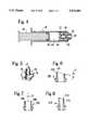
- FIG. 1is a perspective view of the liquid medicament delivery system of the present invention, shown in one intended environment;
- FIG. 2is a cross-sectional view of the liquid medicament delivery system of the present invention, as seen along the line 2--2 in FIG. 1;
- FIG. 3is a cross-sectional view of the liquid medicament delivery system of the present invention, as would be seen along the line 2--2 in FIG. 1, with the handle partially advanced into the syringe further than as shown in FIG. 2;
- FIG. 4is another cross-sectional view of the liquid medicament delivery system of the present invention, as would be seen along the line 2--2 in FIG. 1, with the handle advanced into the syringe further than as shown in FIG. 3;
- FIG. 5is an isometric view of a nipple of the present invention.
- FIG. 6is a cross-sectional view of an alternate embodiment of the nipple of the present invention.
- FIG. 7is a cross-sectional view of another alternate embodiment of the nipple of the present invention.
- FIG. 8is a cross-sectional view of still another alternate embodiment of the nipple of the present invention.
- a liquid medicament delivery systemis shown, generally designated 10.
- the delivery system 10can be engaged with a suitable intravenous (IV) infusion connector, such as the Y-site valve 12, for infusing liquid from the delivery system 10 through an IV line 14 into a patient 16.
- IVintravenous
- the Y-site valveis a needleless connector, i.e., the ports of the Y-site valve are configured for engaging another complementary needleless connector, such as a luer fitting.
- the system 10is essentially a syringe having a plurality of fluid medicaments therein. More specifically, the system 10 includes an elongated, generally cylindrical syringe vessel 18 forming a chamber 19, and the vessel 18 has a port 20 formed in one end thereof.
- the port 20includes a luer fitting 22 for engaging a complementary luer fitting (e.g., one of the luer fitting on the Y-site valve 12).
- the luer fitting 22can be a male luer fitting, as shown, or a female luer fitting, as appropriate for the particular application of the system 10.
- FIG. 2shows that the port 20 has an inwardly-protruding nipple 24.
- a passageway 26is established by the port 20 for permitting fluid communication out of the chamber 19 through the passageway 26.
- the syringe vessel 18 and associated port 20are made of a biocompatible material, such as transparent glass or plastic, that is suitable for use as a syringe.
- FIG. 2shows that the system 10 has a plurality of plungers for sequentially urging a plurality of fluids out of the chamber 19.
- three plungersare serially disposed in the chamber 19.
- first and second barrier plungers 28, 30are slidably disposed in the chamber 19
- a syringe plunger 32is slidably disposed in the chamber 19.
- Each plunger 28, 30, 32is made of a biocompatible resilient material, such as rubber, silicone, or urethane.
- each plunger 28, 30, 32is generally formed as a disc.
- Each plunger 28, 30, 32has a plurality of ring-like lands that engage the inside wall of the syringe vessel 18 in an interference fit to form a fluid-tight seal between the particular plunger 28, 30, 32 and the syringe vessel 18.
- the first barrier plunger 28has lands 34 that engage the inside wall of the syringe vessel 18 in an interference fit to form a fluid-tight seal between the first barrier plunger 28 and the syringe vessel 18.
- FIG. 2further shows that each of the barrier plungers 28, 30 has a respective channel 36, 38 formed therethrough that establishes a pathway for fluid communication therethrough.
- Each channel 36, 38is preferably coaxial with its respective plunger 28, 30.
- meansare provided in each plunger 28, 30 for blocking the associated channel 36, 38, as described more fully below.
- a plurality of fluid medicamentscan be held in the chamber 19 of the syringe vessel 18 separate from each other.
- a first fluid 40is held in the chamber 19 between the first barrier plunger 28 and the port 20.
- a second fluid 42is held in the chamber 19 between the first barrier plunger 28 and the second barrier plunger 30.
- a third fluid 44is held between the second barrier plunger 30 and the syringe plunger 32.
- These fluids 40, 42, 44cannot mix with each other because of the fluid-tight seals between the fluids 40, 42, 44 which are established by the plungers 28, 30, 32. Consequently, the fluids 40, 42, 44 do not have to be compatible with each other.
- each of the fluids 40, 42, 44can be any appropriate fluid, e.g., saline solution, heparin, medicinal compound, etc., for IV infusion to the patient 16.
- a handle 46is connected to the syringe plunger 32 for providing a means for advancing the syringe plunger 32 into the chamber 19 of the syringe vessel 18.
- the handle 46has an elongated shank 47 that is made of rigid plastic.
- the distal end 49 of the handle 46is formed with a head 48, and the head 48 is embedded in the syringe. If desired, the head 48 of the handle 46 can be bonded or screwed to the syringe plunger 32. While FIG. 2 indicates that the head 48 is formed separately from the handle 46, it is to be understood that for ease of manufacture, the head 48 can be formed integrally with the handle 46.
- the first and second barrier plungers 28, 30include means for selectively blocking their respective channels 36, 38.
- each channel 36, 38has a respective fluid-tight membrane 70, 72 positioned therein for selectively blocking the channel 36, 38.
- the membranes 70, 72are substantially identical in construction and operation.
- each membrane 36, 38is formed integrally with its respective plunger 28, 30.
- a nipple 74is attached to the first barrier plunger 28 and extends toward the-channel 38 of the second barrier plunger 30.
- the nipple 74can slide within the channel 38 of the second barrier plunger 30 and is configured for breaking the membrane 72 of the second barrier plunger 30 when the second barrier plunger 30 is urged against the nipple 74.
- the nipple 74has a disc-shaped base 75 and a generally frusto-conical shaped protrusion 77, although other suitable configurations that are appropriate for breaking, e.g., puncturing, the membrane 72 can be used.
- the nipple 74is hollow, so that fluid can flow through the nipple 74 to the channel 36 of the first barrier plunger 28.
- at least one groove 78is formed longitudinally in the protrusion 77, to prevent trapping fluid between the nipple 74 and the plunger 30. If desired, the groove 78 can extend radially into the base 75.
- at least one groove 76(FIG. 2) may be formed in the nipple 24.
- FIGS. 1 and 2In the operation of the system 10, reference is made to FIGS. 1 and 2.
- the luer fitting 22 of the system 10is engaged with a component, e.g., the Y-site valve 12, through which it is desired to infuse fluid from the system 10.
- an operatoradvances the syringe plunger 32 into the syringe vessel 18 by appropriately manipulating the handle 46.
- the third fluid 44is pressurized, causing the third fluid 44 to in turn urge against the second barrier plunger 30.
- the second barrier plunger 30is thereby caused to urge against the second fluid 42, which causes the second fluid 42 to urge against the first barrier plunger 28.
- the first barrier plunger 28in turn is caused to advance into the first fluid 40, causing the first fluid 40 to be expelled through the fluid passageway 26.
- a hydraulic lockexists within the syringe vessel 18.
- the hydraulic locktransfers this force through the second and third fluids 42, 44 and the barrier plungers 28, 30 to cause the first fluid 40 to be expelled from the system 10 through the passageway 26.
- the nipple 24engages the channel 36 of the first barrier plunger 28 and breaks the membrane 70 of the first barrier plunger 28. Any residual first fluid 40 is not trapped between the first barrier plunger 28 and the syringe vessel 18, but instead flows proximally through the groove 76 of the nipple 24 of the port 20 and out of the port 20.
- the operatoradvances the syringe plunger 32 further into the syringe vessel 18.
- the operatorurges against the handle 46 to advance the syringe plunger 32 into the syringe vessel 18, to expel the second fluid 42 through the channel 36 of the first barrier plunger 28 and port 20.
- the operatorurges against the handle 46 to advance the syringe plunger 3 into the third fluid 44. This causes the third fluid 44 to be expelled through the channels 36, 38 of the barrier plungers 28, 30 and through to port 20.
- the present inventionprovides for the sequential infusion of two or more fluids that are held in a single syringe into an IV connector and thence into an IV line or other IV component.
- multiple doses of a single medicamentcan be held in the syringe and infused without undue danger of over-infusion of more than a single dose at one time.
- FIGS. 6, 7, and 8alternate embodiments of nipples are shown which can be used in place of the nipple 74 shown in FIG. 2.
- the present inventioncontemplates the use of non-sharp, i.e., blunt or dull nipples, to reduce the likelihood of inadvertent punctures of medical personnel. Owing to the reduced thickness of the frangible membranes of the present invention, however, the nipples disclosed below can nevertheless break the membranes to establish respective pathways for fluid communication through the membranes.
- a nipple 100is shown in FIG. 6 which has a non-sharp distal end 102.
- the distal end 102has a bevel angle ⁇ with respect to the transverse dimension of the nipple 100 of less than about twenty (20) degrees.
- the distal end 102has a flat and, hence, a blunt surface 104. Accordingly, with this combination of structure, it is highly unlikely that the nipple 100 could puncture human skin when handled by medical personnel during manufacture or syringe preparation.
- FIG. 7shows a nipple 106 that has a distal end 108 which has a flat and, hence, blunt or dull surface 110 which is perpendicular to the longitudinal axis 112 of the nipple 106. Accordingly, with this combination of structure, it is highly unlikely that the nipple 106 could puncture human skin when handled by medical personnel during manufacture or syringe preparation.
- FIG. 8shows that a nipple 114 can have a bevelled distal end 116, and that the distal end 116 has a rounded and, hence, a blunt or dull surface 118. Consequently, it is highly unlikely that the nipple 114 could puncture human skin.
Landscapes
- Health & Medical Sciences (AREA)
- Vascular Medicine (AREA)
- Engineering & Computer Science (AREA)
- Anesthesiology (AREA)
- Biomedical Technology (AREA)
- Heart & Thoracic Surgery (AREA)
- Hematology (AREA)
- Life Sciences & Earth Sciences (AREA)
- Animal Behavior & Ethology (AREA)
- General Health & Medical Sciences (AREA)
- Public Health (AREA)
- Veterinary Medicine (AREA)
- Infusion, Injection, And Reservoir Apparatuses (AREA)
Abstract
Description
Claims (16)
Priority Applications (1)
| Application Number | Priority Date | Filing Date | Title |
|---|---|---|---|
| US08/095,732US5476449A (en) | 1992-12-28 | 1993-07-22 | Needleless multi-liquid medicament delivery system with membranes |
Applications Claiming Priority (2)
| Application Number | Priority Date | Filing Date | Title |
|---|---|---|---|
| US99786192A | 1992-12-28 | 1992-12-28 | |
| US08/095,732US5476449A (en) | 1992-12-28 | 1993-07-22 | Needleless multi-liquid medicament delivery system with membranes |
Related Parent Applications (1)
| Application Number | Title | Priority Date | Filing Date |
|---|---|---|---|
| US99786192AContinuation-In-Part | 1992-12-28 | 1992-12-28 |
Publications (1)
| Publication Number | Publication Date |
|---|---|
| US5476449Atrue US5476449A (en) | 1995-12-19 |
Family
ID=25544490
Family Applications (1)
| Application Number | Title | Priority Date | Filing Date |
|---|---|---|---|
| US08/095,732Expired - LifetimeUS5476449A (en) | 1992-12-28 | 1993-07-22 | Needleless multi-liquid medicament delivery system with membranes |
Country Status (1)
| Country | Link |
|---|---|
| US (1) | US5476449A (en) |
Cited By (51)
| Publication number | Priority date | Publication date | Assignee | Title |
|---|---|---|---|---|
| US5637087A (en)* | 1995-03-22 | 1997-06-10 | Abbott Laboratories | Prefilled, two-constituent syringe |
| US5772630A (en)* | 1993-09-29 | 1998-06-30 | Pharmacia Ab | Injection cartridges |
| US5891087A (en)* | 1996-03-15 | 1999-04-06 | Takeda Chemical Industries, Ltd. | Mixing syringe |
| WO2000048662A1 (en)* | 1999-02-16 | 2000-08-24 | Prismedical Corporation | Single dose delivery device |
| US6309371B1 (en) | 1998-07-27 | 2001-10-30 | Medi-Jet Corporation | Injection-assisting probe for medical injector assembly |
| US6394981B2 (en)* | 1996-04-30 | 2002-05-28 | Medtronic, Inc. | Method and apparatus for drug infusion |
| US6413784B1 (en)* | 1996-12-05 | 2002-07-02 | Idego Aps | Multi-sectioned fluid delivery devices for detecting target molecules by immunoassay |
| US20040044316A1 (en)* | 2002-08-30 | 2004-03-04 | Greenfield Christian John | Syringe for sequential delivery of different fluids |
| JP2004097583A (en)* | 2002-09-11 | 2004-04-02 | Nipro Corp | Two-component mixing type pre-filled syringe |
| US6723074B1 (en) | 2002-04-09 | 2004-04-20 | Thor R. Halseth | Sequential delivery syringe |
| US20040167480A1 (en)* | 2003-02-21 | 2004-08-26 | Advanced Medical Optics, Inc. | Administration of multiple viscoelastic solutions with a multi-compartment syringe |
| US20040171984A1 (en)* | 2002-08-30 | 2004-09-02 | Greenfield Christian John | Syringe for sequential delivery of different fluids |
| US20040219365A1 (en)* | 2003-05-01 | 2004-11-04 | Solutia Incorporated | Polyvinyl butyral sheet having antiblocking characteristics |
| US20040243055A1 (en)* | 2003-06-02 | 2004-12-02 | Tan Sharon Mi Lyn | Medical devices |
| US20040254526A1 (en)* | 1993-07-31 | 2004-12-16 | Aradigm Corporation | Needle-less injector |
| US20050171506A1 (en)* | 2004-02-02 | 2005-08-04 | Stephen Hallahan | Method and device |
| US20050240157A1 (en)* | 2004-04-21 | 2005-10-27 | Shai Amisar | Multi-stage drug administration device and method |
| US7008403B1 (en)* | 2002-07-19 | 2006-03-07 | Cognitive Ventures Corporation | Infusion pump and method for use |
| US20080114304A1 (en)* | 2006-11-13 | 2008-05-15 | Medical Components, Inc | Syringe for sequential expression of different liquids and method of using same |
| US20080287884A1 (en)* | 2007-04-17 | 2008-11-20 | Warden Matthew P | Convertible syringe system |
| US20090191067A1 (en)* | 2008-01-25 | 2009-07-30 | Phluid,Inc. | Two chamber pumps and related methods |
| US20090314803A1 (en)* | 2006-08-22 | 2009-12-24 | Medmix Systems Ag | Device and method for storing, mixing and dispensing components |
| US20100106139A1 (en)* | 2008-10-29 | 2010-04-29 | Steven Schulhof | Syringe-Carpule Assembly |
| US20100186738A1 (en)* | 2007-07-26 | 2010-07-29 | Canon Kabushiki Kaisha | Liquid cartridge |
| US8056582B2 (en) | 2008-08-08 | 2011-11-15 | Tandem Diabetes Care, Inc. | System of stepped flow rate regulation using compressible members |
| US20120258421A1 (en)* | 2011-04-05 | 2012-10-11 | Tyco Healthcare Group Lp | Anesthetic Syringe |
| US8287495B2 (en) | 2009-07-30 | 2012-10-16 | Tandem Diabetes Care, Inc. | Infusion pump system with disposable cartridge having pressure venting and pressure feedback |
| US20120265171A1 (en)* | 2011-04-18 | 2012-10-18 | Thorne Consulting And Intellectual Property, Llc | Pressure actuated valve for multi-chamber syringe applications |
| US20120323173A1 (en)* | 2011-04-18 | 2012-12-20 | Thorne Consulting And Intellectual Property, Llc | Medical syringe filling and valving |
| US8408421B2 (en) | 2008-09-16 | 2013-04-02 | Tandem Diabetes Care, Inc. | Flow regulating stopcocks and related methods |
| US20130116657A1 (en)* | 2004-02-02 | 2013-05-09 | Bimeda Research & Development Limited | Method and device |
| US8506538B2 (en) | 2007-12-05 | 2013-08-13 | Covidien Lp | Device for reducing microbial contamination |
| US8506527B2 (en)* | 2008-06-30 | 2013-08-13 | Covidien Lp | Syringe assembly with plunger having a secondary dispensing reservoir |
| US8573027B2 (en) | 2009-02-27 | 2013-11-05 | Tandem Diabetes Care, Inc. | Methods and devices for determination of flow reservoir volume |
| US20130296778A1 (en)* | 2010-12-06 | 2013-11-07 | Novo Nordisk Healthcare Ag | Wheel Operated Drug Delivery Device |
| US8650937B2 (en) | 2008-09-19 | 2014-02-18 | Tandem Diabetes Care, Inc. | Solute concentration measurement device and related methods |
| US20140296791A1 (en)* | 2013-02-27 | 2014-10-02 | Season Sze-Shun Wong | Pre-filled multi-chamber device for sequential delivery |
| US8870028B2 (en) | 2012-05-25 | 2014-10-28 | Restek Corporation | Dispensing device |
| US8986253B2 (en) | 2008-01-25 | 2015-03-24 | Tandem Diabetes Care, Inc. | Two chamber pumps and related methods |
| US20150108170A1 (en)* | 2013-10-18 | 2015-04-23 | Yibing Li | Device for dispensing liquid with high precision |
| US9022995B2 (en) | 2011-08-01 | 2015-05-05 | Synchrojet Llc | Stopper/plunger for carpules of syringe-carpule assembly |
| US9250106B2 (en) | 2009-02-27 | 2016-02-02 | Tandem Diabetes Care, Inc. | Methods and devices for determination of flow reservoir volume |
| US9555186B2 (en) | 2012-06-05 | 2017-01-31 | Tandem Diabetes Care, Inc. | Infusion pump system with disposable cartridge having pressure venting and pressure feedback |
| US9694134B2 (en) | 2013-09-16 | 2017-07-04 | Zoetis Services Llc | Assembly for sequentially delivering substances, and associated methods |
| US9962486B2 (en) | 2013-03-14 | 2018-05-08 | Tandem Diabetes Care, Inc. | System and method for detecting occlusions in an infusion pump |
| US20180310974A1 (en)* | 2017-04-28 | 2018-11-01 | Heraeus Medical Gmbh | Bone cement application device with closure on the delivery plunger |
| US20180338904A1 (en)* | 2012-09-27 | 2018-11-29 | Inguran, Llc | Single channel, multiple drug delivery device and methods |
| US10258736B2 (en) | 2012-05-17 | 2019-04-16 | Tandem Diabetes Care, Inc. | Systems including vial adapter for fluid transfer |
| US11351092B2 (en)* | 2018-12-17 | 2022-06-07 | John C. Sands | System and method for mixing and delivering a solution |
| US20220288275A1 (en)* | 2018-01-29 | 2022-09-15 | Omer Peled | System and method for harvesting autologous adipose tissue |
| US11565047B2 (en) | 2017-01-09 | 2023-01-31 | Verily Life Sciences Llc | Wearable non-liquid medication injection device |
Citations (14)
| Publication number | Priority date | Publication date | Assignee | Title |
|---|---|---|---|---|
| US2159217A (en)* | 1937-11-05 | 1939-05-23 | Cook Lab Inc | Controllable transfer element for multiple ampules |
| US2193322A (en)* | 1938-04-30 | 1940-03-12 | Cook Lab Inc | Controllable transfer element for multiple compartment ampules |
| US3785379A (en)* | 1971-08-12 | 1974-01-15 | M Cohen | Syringe for injection of freshly mixed liquid-powder |
| US3911916A (en)* | 1971-10-29 | 1975-10-14 | Peter A Stevens | Sequential injection syringe |
| US3923058A (en)* | 1972-05-19 | 1975-12-02 | Kendall & Co | Multi-chamber syringe |
| US4055177A (en)* | 1976-05-28 | 1977-10-25 | Cohen Milton J | Hypodermic syringe |
| US4059109A (en)* | 1976-07-27 | 1977-11-22 | Tischlinger Edward A | Mixing and dispensing disposable medicament injector |
| US4361149A (en)* | 1977-08-27 | 1982-11-30 | Bunder Glas Gmbh | Injection syringe |
| US4392851A (en)* | 1981-11-23 | 1983-07-12 | Abbott Laboratories | In-line transfer unit |
| US4614437A (en)* | 1984-11-02 | 1986-09-30 | Dougherty Brothers Company | Mixing container and adapter |
| US4629455A (en)* | 1984-02-09 | 1986-12-16 | Terumo Kabushiki Kaisha | Medical instrument |
| US4643721A (en)* | 1984-11-20 | 1987-02-17 | Poutrait-Morin | Multiple compartment ampule for automatic hypodermic syringes |
| US4861335A (en)* | 1985-07-26 | 1989-08-29 | Duoject Medical Systems Inc. | Syringe |
| US5102388A (en)* | 1991-07-15 | 1992-04-07 | Richmond John E | Sequential delivery syringe |
- 1993
- 1993-07-22USUS08/095,732patent/US5476449A/ennot_activeExpired - Lifetime
Patent Citations (14)
| Publication number | Priority date | Publication date | Assignee | Title |
|---|---|---|---|---|
| US2159217A (en)* | 1937-11-05 | 1939-05-23 | Cook Lab Inc | Controllable transfer element for multiple ampules |
| US2193322A (en)* | 1938-04-30 | 1940-03-12 | Cook Lab Inc | Controllable transfer element for multiple compartment ampules |
| US3785379A (en)* | 1971-08-12 | 1974-01-15 | M Cohen | Syringe for injection of freshly mixed liquid-powder |
| US3911916A (en)* | 1971-10-29 | 1975-10-14 | Peter A Stevens | Sequential injection syringe |
| US3923058A (en)* | 1972-05-19 | 1975-12-02 | Kendall & Co | Multi-chamber syringe |
| US4055177A (en)* | 1976-05-28 | 1977-10-25 | Cohen Milton J | Hypodermic syringe |
| US4059109A (en)* | 1976-07-27 | 1977-11-22 | Tischlinger Edward A | Mixing and dispensing disposable medicament injector |
| US4361149A (en)* | 1977-08-27 | 1982-11-30 | Bunder Glas Gmbh | Injection syringe |
| US4392851A (en)* | 1981-11-23 | 1983-07-12 | Abbott Laboratories | In-line transfer unit |
| US4629455A (en)* | 1984-02-09 | 1986-12-16 | Terumo Kabushiki Kaisha | Medical instrument |
| US4614437A (en)* | 1984-11-02 | 1986-09-30 | Dougherty Brothers Company | Mixing container and adapter |
| US4643721A (en)* | 1984-11-20 | 1987-02-17 | Poutrait-Morin | Multiple compartment ampule for automatic hypodermic syringes |
| US4861335A (en)* | 1985-07-26 | 1989-08-29 | Duoject Medical Systems Inc. | Syringe |
| US5102388A (en)* | 1991-07-15 | 1992-04-07 | Richmond John E | Sequential delivery syringe |
Non-Patent Citations (2)
| Title |
|---|
| Vaclok Medallion Syringe Brochure Merit Medical Salt Lake City, Utah 84107 (1992).* |
| Vaclok Medallion Syringe Brochure--Merit Medical--Salt Lake City, Utah 84107 (1992). |
Cited By (86)
| Publication number | Priority date | Publication date | Assignee | Title |
|---|---|---|---|---|
| US20040254526A1 (en)* | 1993-07-31 | 2004-12-16 | Aradigm Corporation | Needle-less injector |
| US5772630A (en)* | 1993-09-29 | 1998-06-30 | Pharmacia Ab | Injection cartridges |
| US5637087A (en)* | 1995-03-22 | 1997-06-10 | Abbott Laboratories | Prefilled, two-constituent syringe |
| US5891087A (en)* | 1996-03-15 | 1999-04-06 | Takeda Chemical Industries, Ltd. | Mixing syringe |
| US6394981B2 (en)* | 1996-04-30 | 2002-05-28 | Medtronic, Inc. | Method and apparatus for drug infusion |
| US6413784B1 (en)* | 1996-12-05 | 2002-07-02 | Idego Aps | Multi-sectioned fluid delivery devices for detecting target molecules by immunoassay |
| US7108675B2 (en) | 1998-07-27 | 2006-09-19 | Antares Pharma, Inc. | Injection-assisting probe for medical injector assembly |
| US6309371B1 (en) | 1998-07-27 | 2001-10-30 | Medi-Jet Corporation | Injection-assisting probe for medical injector assembly |
| US20020058907A1 (en)* | 1998-07-27 | 2002-05-16 | Medi-Ject Corporation | Injection-assisting probe for medical injector assembly |
| WO2000048662A1 (en)* | 1999-02-16 | 2000-08-24 | Prismedical Corporation | Single dose delivery device |
| US20040015128A1 (en)* | 1999-02-16 | 2004-01-22 | Taylor Michael A. | Single dose delivery device |
| US6932791B2 (en) | 1999-02-16 | 2005-08-23 | Prismedical Corporation | Single dose delivery device |
| US6562002B1 (en) | 1999-02-16 | 2003-05-13 | Prismedical Corporation | Single dose delivery device |
| US6723074B1 (en) | 2002-04-09 | 2004-04-20 | Thor R. Halseth | Sequential delivery syringe |
| US7008403B1 (en)* | 2002-07-19 | 2006-03-07 | Cognitive Ventures Corporation | Infusion pump and method for use |
| US20040044316A1 (en)* | 2002-08-30 | 2004-03-04 | Greenfield Christian John | Syringe for sequential delivery of different fluids |
| US20040171984A1 (en)* | 2002-08-30 | 2004-09-02 | Greenfield Christian John | Syringe for sequential delivery of different fluids |
| US7077827B2 (en) | 2002-08-30 | 2006-07-18 | Christian John Greenfield | Syringe for sequential delivery of different fluids |
| JP2004097583A (en)* | 2002-09-11 | 2004-04-02 | Nipro Corp | Two-component mixing type pre-filled syringe |
| US20040167480A1 (en)* | 2003-02-21 | 2004-08-26 | Advanced Medical Optics, Inc. | Administration of multiple viscoelastic solutions with a multi-compartment syringe |
| US20040219365A1 (en)* | 2003-05-01 | 2004-11-04 | Solutia Incorporated | Polyvinyl butyral sheet having antiblocking characteristics |
| US20040243055A1 (en)* | 2003-06-02 | 2004-12-02 | Tan Sharon Mi Lyn | Medical devices |
| US7435237B2 (en)* | 2003-06-02 | 2008-10-14 | Boston Scientific Scimed, Inc. | Mixing syringes with breakable septums |
| US20110022000A1 (en)* | 2004-02-02 | 2011-01-27 | Bimeda Research & Development Limited | Method and device |
| US7828765B2 (en) | 2004-02-02 | 2010-11-09 | Bimeda Research & Development Ltd | Method and device for administering two components into the teat canal of a non-human animal |
| US20130116657A1 (en)* | 2004-02-02 | 2013-05-09 | Bimeda Research & Development Limited | Method and device |
| US8353877B2 (en) | 2004-02-02 | 2013-01-15 | Bimeda Research & Development Limited | Method for administering two components into the teat canal of a non-human animal |
| US9180249B2 (en)* | 2004-02-02 | 2015-11-10 | Bimeda Research & Development Limited | Method and device |
| US20050171506A1 (en)* | 2004-02-02 | 2005-08-04 | Stephen Hallahan | Method and device |
| US20050240157A1 (en)* | 2004-04-21 | 2005-10-27 | Shai Amisar | Multi-stage drug administration device and method |
| US20090314803A1 (en)* | 2006-08-22 | 2009-12-24 | Medmix Systems Ag | Device and method for storing, mixing and dispensing components |
| US8256646B2 (en)* | 2006-08-22 | 2012-09-04 | Medmix Systems Ag | Device and method for storing, mixing and dispensing components |
| US8021349B2 (en)* | 2006-11-13 | 2011-09-20 | Medical Components, Inc. | Method of using a syringe |
| US20080114304A1 (en)* | 2006-11-13 | 2008-05-15 | Medical Components, Inc | Syringe for sequential expression of different liquids and method of using same |
| US8771254B2 (en) | 2006-11-13 | 2014-07-08 | Medical Components, Inc. | Method of using a syringe |
| US8021343B2 (en)* | 2006-11-13 | 2011-09-20 | Medical Components, Inc. | Syringe for sequential expression of different liquids |
| US20100152668A1 (en)* | 2006-11-13 | 2010-06-17 | Medical Components, Inc | Method of Using a Syringe |
| US8771234B2 (en) | 2006-11-13 | 2014-07-08 | Medical Components, Inc. | Syringe for sequential expression of different liquids |
| US20080287884A1 (en)* | 2007-04-17 | 2008-11-20 | Warden Matthew P | Convertible syringe system |
| US20100186738A1 (en)* | 2007-07-26 | 2010-07-29 | Canon Kabushiki Kaisha | Liquid cartridge |
| US8506538B2 (en) | 2007-12-05 | 2013-08-13 | Covidien Lp | Device for reducing microbial contamination |
| US20090191067A1 (en)* | 2008-01-25 | 2009-07-30 | Phluid,Inc. | Two chamber pumps and related methods |
| US8986253B2 (en) | 2008-01-25 | 2015-03-24 | Tandem Diabetes Care, Inc. | Two chamber pumps and related methods |
| US8506527B2 (en)* | 2008-06-30 | 2013-08-13 | Covidien Lp | Syringe assembly with plunger having a secondary dispensing reservoir |
| US8056582B2 (en) | 2008-08-08 | 2011-11-15 | Tandem Diabetes Care, Inc. | System of stepped flow rate regulation using compressible members |
| US8408421B2 (en) | 2008-09-16 | 2013-04-02 | Tandem Diabetes Care, Inc. | Flow regulating stopcocks and related methods |
| US8448824B2 (en) | 2008-09-16 | 2013-05-28 | Tandem Diabetes Care, Inc. | Slideable flow metering devices and related methods |
| US8650937B2 (en) | 2008-09-19 | 2014-02-18 | Tandem Diabetes Care, Inc. | Solute concentration measurement device and related methods |
| US8728054B2 (en) | 2008-10-29 | 2014-05-20 | Synchrojet Llc | Syringe-carpule assembly |
| US20100106139A1 (en)* | 2008-10-29 | 2010-04-29 | Steven Schulhof | Syringe-Carpule Assembly |
| US9250106B2 (en) | 2009-02-27 | 2016-02-02 | Tandem Diabetes Care, Inc. | Methods and devices for determination of flow reservoir volume |
| US8573027B2 (en) | 2009-02-27 | 2013-11-05 | Tandem Diabetes Care, Inc. | Methods and devices for determination of flow reservoir volume |
| US9211377B2 (en) | 2009-07-30 | 2015-12-15 | Tandem Diabetes Care, Inc. | Infusion pump system with disposable cartridge having pressure venting and pressure feedback |
| US11135362B2 (en) | 2009-07-30 | 2021-10-05 | Tandem Diabetes Care, Inc. | Infusion pump systems and methods |
| US8287495B2 (en) | 2009-07-30 | 2012-10-16 | Tandem Diabetes Care, Inc. | Infusion pump system with disposable cartridge having pressure venting and pressure feedback |
| US8758323B2 (en) | 2009-07-30 | 2014-06-24 | Tandem Diabetes Care, Inc. | Infusion pump system with disposable cartridge having pressure venting and pressure feedback |
| US8298184B2 (en) | 2009-07-30 | 2012-10-30 | Tandem Diabetes Care, Inc. | Infusion pump system with disposable cartridge having pressure venting and pressure feedback |
| US12144964B2 (en) | 2009-07-30 | 2024-11-19 | Tandem Diabetes Care, Inc | Infusion pump system with disposable cartridge having pressure venting and pressure feedback |
| US12042627B2 (en) | 2009-07-30 | 2024-07-23 | Tandem Diabetes Care, Inc. | Infusion pump systems and methods |
| US11285263B2 (en) | 2009-07-30 | 2022-03-29 | Tandem Diabetes Care, Inc. | Infusion pump systems and methods |
| US8926561B2 (en) | 2009-07-30 | 2015-01-06 | Tandem Diabetes Care, Inc. | Infusion pump system with disposable cartridge having pressure venting and pressure feedback |
| WO2011056375A3 (en)* | 2009-10-28 | 2011-07-21 | Steven Schulhof | Syringe-carpule assembly |
| JP2014500086A (en)* | 2010-12-06 | 2014-01-09 | ノボ ノルディスク ヘルス ケア アーゲー | Wheel operated drug delivery device |
| US20130296778A1 (en)* | 2010-12-06 | 2013-11-07 | Novo Nordisk Healthcare Ag | Wheel Operated Drug Delivery Device |
| US20120258421A1 (en)* | 2011-04-05 | 2012-10-11 | Tyco Healthcare Group Lp | Anesthetic Syringe |
| US9289272B2 (en)* | 2011-04-05 | 2016-03-22 | Covidien Lp | Anesthetic syringe |
| US20120265171A1 (en)* | 2011-04-18 | 2012-10-18 | Thorne Consulting And Intellectual Property, Llc | Pressure actuated valve for multi-chamber syringe applications |
| US20120323173A1 (en)* | 2011-04-18 | 2012-12-20 | Thorne Consulting And Intellectual Property, Llc | Medical syringe filling and valving |
| US9289562B2 (en)* | 2011-04-18 | 2016-03-22 | THORNE CONSULTING and INTELETUAL PROPERTY, LLC | Pressure actuated valve for multi-chamber syringe applications |
| US8992505B2 (en)* | 2011-04-18 | 2015-03-31 | Thorne Consulting & Intellectual Property, LLC | Medical syringe filling and valving |
| US9022995B2 (en) | 2011-08-01 | 2015-05-05 | Synchrojet Llc | Stopper/plunger for carpules of syringe-carpule assembly |
| US10258736B2 (en) | 2012-05-17 | 2019-04-16 | Tandem Diabetes Care, Inc. | Systems including vial adapter for fluid transfer |
| US9339840B2 (en) | 2012-05-25 | 2016-05-17 | Restek Corporation | Dispensing device |
| US8870028B2 (en) | 2012-05-25 | 2014-10-28 | Restek Corporation | Dispensing device |
| US9555186B2 (en) | 2012-06-05 | 2017-01-31 | Tandem Diabetes Care, Inc. | Infusion pump system with disposable cartridge having pressure venting and pressure feedback |
| US20180338904A1 (en)* | 2012-09-27 | 2018-11-29 | Inguran, Llc | Single channel, multiple drug delivery device and methods |
| US20140296791A1 (en)* | 2013-02-27 | 2014-10-02 | Season Sze-Shun Wong | Pre-filled multi-chamber device for sequential delivery |
| US9962486B2 (en) | 2013-03-14 | 2018-05-08 | Tandem Diabetes Care, Inc. | System and method for detecting occlusions in an infusion pump |
| US9694134B2 (en) | 2013-09-16 | 2017-07-04 | Zoetis Services Llc | Assembly for sequentially delivering substances, and associated methods |
| US20150108170A1 (en)* | 2013-10-18 | 2015-04-23 | Yibing Li | Device for dispensing liquid with high precision |
| US11565047B2 (en) | 2017-01-09 | 2023-01-31 | Verily Life Sciences Llc | Wearable non-liquid medication injection device |
| US20180310974A1 (en)* | 2017-04-28 | 2018-11-01 | Heraeus Medical Gmbh | Bone cement application device with closure on the delivery plunger |
| US11103295B2 (en)* | 2017-04-28 | 2021-08-31 | Heraeus Medical Gmbh | Bone cement application device with closure on the delivery plunger |
| US20220288275A1 (en)* | 2018-01-29 | 2022-09-15 | Omer Peled | System and method for harvesting autologous adipose tissue |
| US12023431B2 (en)* | 2018-01-29 | 2024-07-02 | Omer Peled | System and method for harvesting autologous adipose tissue |
| US11351092B2 (en)* | 2018-12-17 | 2022-06-07 | John C. Sands | System and method for mixing and delivering a solution |
Similar Documents
| Publication | Publication Date | Title |
|---|---|---|
| US5476449A (en) | Needleless multi-liquid medicament delivery system with membranes | |
| US5298024A (en) | Multi-liquid medicament delivery system with reflex valves | |
| JP7535639B2 (en) | Storage device for single or multiple containers | |
| JP5795613B2 (en) | Needleless additive control valve | |
| US11083848B2 (en) | Flush syringe having anti-reflux features | |
| KR200421308Y1 (en) | Medical valve with fluid escape space | |
| JP2736510B2 (en) | In-line drug release device and release method for use with a standard intravenous set | |
| EP0947212B1 (en) | Self-priming needle-free "Y"-adapter | |
| EP3222310B1 (en) | Syringe for sequential expression of different liquids | |
| KR200396136Y1 (en) | Medical valve with tire seal | |
| US8152778B2 (en) | Device for interfacing with standard luer lock syringes | |
| EP3345640B1 (en) | Positive displacement flush syringe | |
| CA2539813C (en) | Flush syringe having anti-reflux features | |
| US7654996B2 (en) | Catheter flushing fluid lock system and method | |
| CA2539785C (en) | Flush syringe having anti-reflux stopper | |
| EP2168620B1 (en) | Diluent/Medication Mixing Syringe Assembly | |
| KR20160001372U (en) | Liquid transfer devices for use with infusion liquid containers | |
| MXPA06006418A (en) | Flush syringe having anti-reflux stopper. | |
| US20040210201A1 (en) | Device for maintaining catheter lumen patency | |
| JP2024009111A (en) | Dual chamber syringe with dual lumen intravenous set | |
| JP4658570B2 (en) | Infusion tube, chemical solution administration set and connection adapter | |
| CA3174945A1 (en) | Dual chamber syringe assembly |
Legal Events
| Date | Code | Title | Description |
|---|---|---|---|
| STPP | Information on status: patent application and granting procedure in general | Free format text:APPLICATION UNDERGOING PREEXAM PROCESSING | |
| FPAY | Fee payment | Year of fee payment:4 | |
| FPAY | Fee payment | Year of fee payment:8 | |
| AS | Assignment | Owner name:BATTELLE ENERGY ALLIANCE, LLC, IDAHO Free format text:ASSIGNMENT OF ASSIGNORS INTEREST;ASSIGNOR:BECHTEL BWXT IDAHO, LLC;REEL/FRAME:016226/0765 Effective date:20050201 Owner name:BATTELLE ENERGY ALLIANCE, LLC,IDAHO Free format text:ASSIGNMENT OF ASSIGNORS INTEREST;ASSIGNOR:BECHTEL BWXT IDAHO, LLC;REEL/FRAME:016226/0765 Effective date:20050201 | |
| FEPP | Fee payment procedure | Free format text:PAT HOLDER NO LONGER CLAIMS SMALL ENTITY STATUS, ENTITY STATUS SET TO UNDISCOUNTED (ORIGINAL EVENT CODE: STOL); ENTITY STATUS OF PATENT OWNER: LARGE ENTITY | |
| REFU | Refund | Free format text:REFUND - PAYMENT OF MAINTENANCE FEE, 12TH YEAR, LARGE ENTITY (ORIGINAL EVENT CODE: R1553); ENTITY STATUS OF PATENT OWNER: LARGE ENTITY | |
| FPAY | Fee payment | Year of fee payment:12 | |
| SULP | Surcharge for late payment | Year of fee payment:11 |