US5476102A - Biopsy needle assembly and guide - Google Patents
Biopsy needle assembly and guideDownload PDFInfo
- Publication number
- US5476102A US5476102AUS08/396,873US39687395AUS5476102AUS 5476102 AUS5476102 AUS 5476102AUS 39687395 AUS39687395 AUS 39687395AUS 5476102 AUS5476102 AUS 5476102A
- Authority
- US
- United States
- Prior art keywords
- cannula
- guide
- handle
- distal end
- probe
- Prior art date
- Legal status (The legal status is an assumption and is not a legal conclusion. Google has not performed a legal analysis and makes no representation as to the accuracy of the status listed.)
- Expired - Lifetime
Links
- 238000001574biopsyMethods0.000titleclaimsabstractdescription19
- 239000000523sampleSubstances0.000claimsabstractdescription19
- 238000003780insertionMethods0.000claimsabstractdescription7
- 230000037431insertionEffects0.000claimsabstractdescription7
- 239000000463materialSubstances0.000claimsdescription3
- 238000011084recoveryMethods0.000claims1
- 238000007470bone biopsyMethods0.000abstractdescription2
- 210000001185bone marrowAnatomy0.000description21
- 210000000988bone and boneAnatomy0.000description12
- 238000000034methodMethods0.000description7
- 210000003811fingerAnatomy0.000description5
- KAKZBPTYRLMSJV-UHFFFAOYSA-NButadieneChemical compoundC=CC=CKAKZBPTYRLMSJV-UHFFFAOYSA-N0.000description2
- PPBRXRYQALVLMV-UHFFFAOYSA-NStyreneChemical compoundC=CC1=CC=CC=C1PPBRXRYQALVLMV-UHFFFAOYSA-N0.000description2
- 239000012530fluidSubstances0.000description2
- 238000007373indentationMethods0.000description2
- 210000000707wristAnatomy0.000description2
- NLHHRLWOUZZQLW-UHFFFAOYSA-NAcrylonitrileChemical compoundC=CC#NNLHHRLWOUZZQLW-UHFFFAOYSA-N0.000description1
- 206010028980NeoplasmDiseases0.000description1
- 239000004743PolypropyleneSubstances0.000description1
- 239000004793PolystyreneSubstances0.000description1
- 201000011510cancerDiseases0.000description1
- 230000006835compressionEffects0.000description1
- 238000007906compressionMethods0.000description1
- 238000003745diagnosisMethods0.000description1
- 201000010099diseaseDiseases0.000description1
- 208000037265diseases, disorders, signs and symptomsDiseases0.000description1
- 210000000245forearmAnatomy0.000description1
- 210000005224forefingerAnatomy0.000description1
- 229920001903high density polyethylenePolymers0.000description1
- 239000004700high-density polyethyleneSubstances0.000description1
- 208000014674injuryDiseases0.000description1
- 239000002991molded plasticSubstances0.000description1
- 230000000149penetrating effectEffects0.000description1
- 230000035515penetrationEffects0.000description1
- 239000004417polycarbonateSubstances0.000description1
- 229920000515polycarbonatePolymers0.000description1
- 229920000728polyesterPolymers0.000description1
- 229920000642polymerPolymers0.000description1
- 229920000098polyolefinPolymers0.000description1
- -1polypropylenePolymers0.000description1
- 229920001155polypropylenePolymers0.000description1
- 229920002223polystyrenePolymers0.000description1
- 210000004872soft tissueAnatomy0.000description1
- 229920001897terpolymerPolymers0.000description1
- 229920001169thermoplasticPolymers0.000description1
- 239000004416thermosoftening plasticSubstances0.000description1
- 210000003813thumbAnatomy0.000description1
- 210000001519tissueAnatomy0.000description1
- 238000002054transplantationMethods0.000description1
- 230000008733traumaEffects0.000description1
Images


Classifications
- A—HUMAN NECESSITIES
- A61—MEDICAL OR VETERINARY SCIENCE; HYGIENE
- A61B—DIAGNOSIS; SURGERY; IDENTIFICATION
- A61B10/00—Instruments for taking body samples for diagnostic purposes; Other methods or instruments for diagnosis, e.g. for vaccination diagnosis, sex determination or ovulation-period determination; Throat striking implements
- A61B10/02—Instruments for taking cell samples or for biopsy
- A61B10/0233—Pointed or sharp biopsy instruments
- A61B10/025—Pointed or sharp biopsy instruments for taking bone, bone marrow or cartilage samples
Definitions
- the inventionrelates generally to the field of medical instruments, and more particularly to those instruments employed in biopsy, aspiration, and transplant procedures of bone marrow.
- a "core" of bone marrowit is desirable to retrieve a "core" of bone marrow to examine bone marrow architecture. This procedure may be useful in determining whether a patient has cancer and the extent of cancerous cells that may exist. Examining a bone marrow core typically involves an extended period of time in which the core is first prepared and then sliced into thin samples which are examined under a microscope.
- All bone marrow biopsy, aspiration and transplant needles currently on the markethave a handle with a cannula extending outwardly from the handle.
- the handleis used by the doctor to apply force to the cannula as the cannula punctures the bone.
- Such needlestypically include a stylet with a sharpened tip which is inserted through the cannula and is used to initially puncture the bone.
- the styletalso serves to occlude the cannula while the bone is punctured so that the marrow sample subsequently taken is free from bone chips.
- the styletis then removed and bone marrow is withdrawn from the patient by manipulating the cannula to cause bone marrow to move into the interior of the cannula. In some cases a slight suction is applied to the cannula to hold the bone marrow in place as the cannula is removed from the patient.
- Bone marrow needleshave traditionally been designed so that the needle is attached to the center of the handle. While many physicians feel comfortable with a centrally attached needle, it has now been discovered that it may be easier to guide a needle with a user's index finger when the needle is not centrally located on the handle of the needle assembly. It has also recently been discovered that when an off-center device is used, it is important to insure that a physician's arm, wrist, and index finger are all generally in alignment with the cannula of the needle to provide enhanced control over the needle. Examples of such devices are described in U.S. Pat. Nos. 4,469,109 and 4,838,282.
- the handlehas an proximal surface which has a somewhat saddle shaped offset surface which, when grasped by a physician, conforms to the shape of the physician's palm.
- the off-center radiuscauses the handle to have a first relatively narrow end and a second relatively wide end.
- the handlealso has a curved, convex, lower surface designed to be easily gripped by a user's fingers.
- the proximal end of the cannulais connected to the lower surface of the handle toward the relatively narrow end.
- the cannula handleis connected to the cannula at an oblique angle that places the user's wrist and forearm in general alignment with the user's index finger and the axis of the cannula.
- the inventionprovides a guide for a bone biopsy needle assembly that includes an elongated tubular cannula having an axially extending lumen therethrough.
- the guidewhich is provided to facilitate insertion of a probe into the cannula for sample removal, has a molded shape with an elongated dimension having first and second ends.
- a cylindrical openingextends through the length of the elongated dimension and has a diameter substantially equal to that of the interior lumen of the cannula.
- a flared outward enlargement of the cylindrical opening at each of the first and second endsprovides for easy alignment of one of the ends with the distal end of the cannula and the other end forms a guide for insertion of a probe into the distal end of the cannula for removal of the biopsy specimen.
- the guide of this inventionis preferably of an hourglass shape. Further aspects of the invention will be apparent from the detailed description and accompanying drawings.
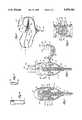
- FIG. 1is a side elevational view of the biopsy needle assembly of this invention
- FIG. 2is a perspective view of a biopsy needle assembly of this invention with the stylet withdrawn from the cannula;
- FIG. 3is a fragmentary perspective view of the cannula handle component of the system with the cover in the open position to expose the proximal cannula assembly;
- FIG. 4is a fragmentary enlarged view of the cannula tip with parts shown in cross-section;
- FIG. 5is a side elevational expanded fragmentary view of a stylet tip
- FIG. 6is a perspective rear view of the cannula handle with cavity cover in the open position to show the hinge detail
- FIG. 7is a fragmentary cross-sectional view of the handle with stylet in place shown in the closed position
- FIG. 8is a view of the handle of FIG. 7 with the cover shown in the open position and with the stylet partially withdrawn from the cannula;
- FIG. 9is a fragmentary cross-sectional view taken along line 9--9 of FIG. 8;
- FIG. 10is a fragmentary perspective view illustrating the manner in which the device of this invention is grasped and illustrating the initial entry into a body;
- FIG. 11shows a view of the device of FIG. 10 as it is penetrating a bone
- FIG. 12is a view of the device of FIG. 10 after the marrow cavity of the bone has been entered and showing the withdrawal of the stylet;
- FIG. 13shows the device of FIG. 10 during aspiration of material utilizing a syringe
- FIGS. 14-17illustrate the use of the device of FIG. 10 to reenter the bone cavity to obtain a biopsy specimen
- FIG. 18illustrates the use of a probe guide and probe to remove a biopsy specimen from the cannula
- FIG. 19is a side view of the probe guide and fragmentary cannula tip with parts broken away and in section.
- a biopsy needle assembly 10which includes a hollow cannula 12 having an open, sharpened distal end 13, and being attached to a handle 11 at its proximal end.
- Handle 11is provided with a cover 16 that pivots open to the position seen in FIGS. 2 and 3 to expose a gap or hollow portion 19 of the handle into which the cannula hub 30, which is secured to the proximal end of cannula 12, is open.
- Ends 15 and 17 of handle 14extend laterally and have central axes that are attached to cannula 12 at an oblique angle with respect to the cannula axis so as to form a saddle shaped configuration that will conform to the hand of a user.
- End 15which is designed to be grasped by the forefinger and thumb of the user is of a smaller cross-section and shorter than end 17 which is designed to engage the user's palm.
- Handle 11is formed from a bottom portion 14, which includes cover 16 which is hinged to the bottom portion 14.
- Upper lateral end portions of the handle 15 and 17are preferably formed from a single molded piece connected together by means of a flat connecting portion 21 that forms a bottom to hollow portion 19 of the handle assembly.
- the handlecan, thus, conveniently be formed from two molded parts.
- a hollow tubular cannula hub 30is molded to the proximal end of cannula 12 and serves to secure the cannula 12 to handle 11 by tight frictional engagement of hub 30 in an aperture through the distal surface of bottom 14 of the handle 11. Hub 30 extends upwardly into hollow portion 19.
- cannula hub 30is connected in fluid flow communication with the hollow interior of cannula 12 as can best be seen in FIGS. 7 and 8.
- Cannula hub 30, as well as any other parts coming into fluid contact,are preferably formed from a polystyrene terpolymer of acrylonitrile, butadiene and styrene (ABS) or, alternatively, a polycarbonate polymer.
- ABSacrylonitrile, butadiene and styrene
- a stylet having a shaft 22 and a handle 24fits within the handle 11 with the distal end 26 of the stylet extending beyond the distal end 13 of cannula 12.
- Knob 24is provided with a proximal projection 25 in order to provide additional compression resistance to the knob and to provide a surface against which internal ribs 40 of the handle are supported during use of the instrument.
- Cover portion 16is hingedly connected to the bottom part 14 of handle 11 by means of living hinges 34, 36 and 38.
- living hinges 34, 36 and 38In the preferred configuration of these hinges best seen in FIGS. 6 and 8, it will be noted that the outermost hinges 34 and 36 are pivoted at a higher point on the base portion 14 of the handle than is the inner hinge 38.
- the upper end of central living hinge 38is also hinged nearer the perimeter of cover 16. This causes rotational pivoting of cover 16 as it is opened, causing it to pivot out of the way of knob 14 more rapidly than would otherwise be the case.
- This hinge arrangementalso holds the cover in a relatively elevated position as seen in FIG. 8 when open.
- the handle components 14, 15, 16 and 17are all preferably provided with ribs 40 to provide structural integrity and light weight to the handle 11. These components are all preferably formed from a polyolefin such as a high density polyethylene, polypropylene, or a polyester or similar thermoplastic polymeric material.
- the cover 16is preferably provided with end walls 42 that provide a chamber surrounding knob 24 when the cover is in the closed position. Walls 42 thus provide a degree of resistance to rotation of the knob 24, preventing relative rotation between stylet 22 and cannula 12.
- the base portion 21is provided with upwardly extending projections 44 and 48. Projections 44 on the forward and rearward sides of the handle closely engage curved indentations 46 in the lower part of knob 24. Knob 24 also fits tightly over the outside of projections 48, thus forming a structure that prevents relative rotation of stylet 22 and cannula 12 even when substantial force is applied to the needle assembly by the physician.
- Lip 54 of cover 16fits within the bottom part of handle 14 as can be seen in FIG. 7.
- An indentation 58is provided in lower handle portion 14 to matingly receive a projection 56 of the cover in order to retain the cover in a closed position.
- a ridge 60is provided to form a surface to be grasped in order to open cover 16.
- FIGS. 10-19The procedure for use of the instrument of this invention is shown in FIGS. 10-19.
- the needlegrasped in physician's hand 70, is introduced through an incision, through soft tissue 72 toward and into contact with bone structure 74, usually the posterior iliac crest.
- the needleis advanced into the marrow cavity by alternating 45 clockwise/counter-clockwise rotation.
- the cover 16is then opened as seen in FIG. 12 and the stylet removed from the cannula.
- For sample aspiration syringe 76is then attached to the cannula hub 30, which is preferably provided with a luer fitting for that purpose. Negative pressure is applied by quickly withdrawing the syringe plunger to remove an aspirated specimen.
- the biopsy procedureis illustrated in FIGS. 15-19, wherein another penetration to the marrow cavity is made, and after removal of the stylet, the cannula is advanced into the marrow cavity to obtain a specimen.
- a knob(not shown) similar to the stylet knob 24 is included with the needle assembly and is placed in the handle to fill the space provided for knob 24.
- the specimenis detached from surrounding tissue by redirection and rotation of the cannula a number of times in each direction.
- the specimenis removed from the cannula as shown in FIG. 18 by introducing a probe 82 through the distal end of the cannula utilizing the probe guide 80 to insure easy insertion of the probe into the lumen of the cannula.
- the biopsy specimenis then pushed up into the proximal end of the cannula and through the cannula hub.
- probe guide 80is preferably a molded plastic shape in the form of a generally hourglass configuration.
- a cylindrical opening 81extends through the length of said elongated dimension of the guide between its ends.
- the cylindrical elongated openinghas a diameter substantially equal to that of said interior lumen of cannula 12.
Landscapes
- Health & Medical Sciences (AREA)
- Life Sciences & Earth Sciences (AREA)
- Biomedical Technology (AREA)
- Molecular Biology (AREA)
- Rheumatology (AREA)
- Pathology (AREA)
- Immunology (AREA)
- Engineering & Computer Science (AREA)
- Hematology (AREA)
- Heart & Thoracic Surgery (AREA)
- Medical Informatics (AREA)
- Orthopedic Medicine & Surgery (AREA)
- Surgery (AREA)
- Animal Behavior & Ethology (AREA)
- General Health & Medical Sciences (AREA)
- Public Health (AREA)
- Veterinary Medicine (AREA)
- Measurement Of The Respiration, Hearing Ability, Form, And Blood Characteristics Of Living Organisms (AREA)
- Surgical Instruments (AREA)
Abstract
Description
Claims (3)
Priority Applications (1)
| Application Number | Priority Date | Filing Date | Title |
|---|---|---|---|
| US08/396,873US5476102A (en) | 1994-06-29 | 1995-03-01 | Biopsy needle assembly and guide |
Applications Claiming Priority (2)
| Application Number | Priority Date | Filing Date | Title |
|---|---|---|---|
| US26823094A | 1994-06-29 | 1994-06-29 | |
| US08/396,873US5476102A (en) | 1994-06-29 | 1995-03-01 | Biopsy needle assembly and guide |
Related Parent Applications (1)
| Application Number | Title | Priority Date | Filing Date |
|---|---|---|---|
| US26823094AContinuation | 1994-06-29 | 1994-06-29 |
Publications (1)
| Publication Number | Publication Date |
|---|---|
| US5476102Atrue US5476102A (en) | 1995-12-19 |
Family
ID=23022047
Family Applications (1)
| Application Number | Title | Priority Date | Filing Date |
|---|---|---|---|
| US08/396,873Expired - LifetimeUS5476102A (en) | 1994-06-29 | 1995-03-01 | Biopsy needle assembly and guide |
Country Status (3)
| Country | Link |
|---|---|
| US (1) | US5476102A (en) |
| AU (1) | AU2951195A (en) |
| WO (1) | WO1996000523A1 (en) |
Cited By (31)
| Publication number | Priority date | Publication date | Assignee | Title |
|---|---|---|---|---|
| USD379229S (en)* | 1995-08-28 | 1997-05-13 | Baxter International, Inc. | Bone marrow biopsy needle |
| US6221029B1 (en) | 1999-05-13 | 2001-04-24 | Stryker Corporation | Universal biopsy system |
| US6280399B1 (en) | 1998-10-06 | 2001-08-28 | Allegiance Corporation | Substance delivery device for use with a procedure performing instrument |
| US6443910B1 (en) | 2000-04-18 | 2002-09-03 | Allegiance Corporation | Bone marrow biopsy needle |
| US6554778B1 (en) | 2001-01-26 | 2003-04-29 | Manan Medical Products, Inc. | Biopsy device with removable handle |
| US6626848B2 (en)* | 2001-03-30 | 2003-09-30 | Eric M. Neuenfeldt | Method and device to reduce needle insertion force |
| US20040073139A1 (en)* | 2002-10-11 | 2004-04-15 | Hirsch Joshua A. | Cannula for extracting and implanting material |
| US6730043B2 (en) | 2000-04-18 | 2004-05-04 | Allegiance Corporation | Bone marrow biopsy needle |
| US20060142779A1 (en)* | 2004-12-23 | 2006-06-29 | Arthrocare Corporation | Cannula having asymmetrically-shaped threads |
| US7201722B2 (en) | 2000-04-18 | 2007-04-10 | Allegiance Corporation | Bone biopsy instrument having improved sample retention |
| US20080154304A1 (en)* | 2006-12-21 | 2008-06-26 | Arthrocare Corporation | System and method for accessing a tissue structure |
| US20080319342A1 (en)* | 2003-02-24 | 2008-12-25 | Shabaz Martin V | Biopsy device with selectable tissue receiving aperture orientation and site illumination |
| US7572263B2 (en) | 1998-04-01 | 2009-08-11 | Arthrocare Corporation | High pressure applicator |
| US20100023065A1 (en)* | 2008-07-25 | 2010-01-28 | Welch Andrea M | Tissue access device with alignment guide and methods of use |
| US7654735B2 (en) | 2005-11-03 | 2010-02-02 | Covidien Ag | Electronic thermometer |
| US7731692B2 (en) | 2005-07-11 | 2010-06-08 | Covidien Ag | Device for shielding a sharp tip of a cannula and method of using the same |
| US7828773B2 (en) | 2005-07-11 | 2010-11-09 | Covidien Ag | Safety reset key and needle assembly |
| US7850650B2 (en) | 2005-07-11 | 2010-12-14 | Covidien Ag | Needle safety shield with reset |
| US7905857B2 (en) | 2005-07-11 | 2011-03-15 | Covidien Ag | Needle assembly including obturator with safety reset |
| US8123756B2 (en) | 1999-09-30 | 2012-02-28 | Neurotherm, Inc. | High pressure delivery system |
| US8282573B2 (en)* | 2003-02-24 | 2012-10-09 | Senorx, Inc. | Biopsy device with selectable tissue receiving aperture orientation and site illumination |
| US8357104B2 (en) | 2007-11-01 | 2013-01-22 | Coviden Lp | Active stylet safety shield |
| US8834417B2 (en) | 2005-06-06 | 2014-09-16 | Covidien Ag | Needle assembly with removable depth stop |
| EP3189787A1 (en)* | 2006-09-12 | 2017-07-12 | Vidacare LLC | Medical procedures trays and related methods |
| US11103282B1 (en) | 2002-05-31 | 2021-08-31 | Teleflex Life Sciences Limited | Powered drivers, intraosseous devices and methods to access bone marrow |
| US11234683B2 (en) | 2002-05-31 | 2022-02-01 | Teleflex Life Sciences Limited | Assembly for coupling powered driver with intraosseous device |
| US11266441B2 (en) | 2002-05-31 | 2022-03-08 | Teleflex Life Sciences Limited | Penetrator assembly for accessing bone marrow |
| US11324521B2 (en) | 2002-05-31 | 2022-05-10 | Teleflex Life Sciences Limited | Apparatus and method to access bone marrow |
| US11337728B2 (en) | 2002-05-31 | 2022-05-24 | Teleflex Life Sciences Limited | Powered drivers, intraosseous devices and methods to access bone marrow |
| US11426249B2 (en) | 2006-09-12 | 2022-08-30 | Teleflex Life Sciences Limited | Vertebral access system and methods |
| US11771439B2 (en) | 2007-04-04 | 2023-10-03 | Teleflex Life Sciences Limited | Powered driver |
Citations (3)
| Publication number | Priority date | Publication date | Assignee | Title |
|---|---|---|---|---|
| US2919692A (en)* | 1956-02-23 | 1960-01-05 | Ackermann Wolfgang | Vertebral trephine biopsy instruments |
| US4099518A (en)* | 1976-05-10 | 1978-07-11 | Baylis Shelby M | Biopsy apparatus |
| US5005585A (en)* | 1989-04-24 | 1991-04-09 | Marshfield Clinic | Biopsy needle construction |
Family Cites Families (4)
| Publication number | Priority date | Publication date | Assignee | Title |
|---|---|---|---|---|
| US5279306B1 (en)* | 1981-03-16 | 1998-06-02 | Creative Res & Mfg | Biopsy needle |
| US4793363A (en)* | 1986-09-11 | 1988-12-27 | Sherwood Medical Company | Biopsy needle |
| US4838282A (en)* | 1987-02-26 | 1989-06-13 | Manan Manufacturing Co., Inc. | Bone biopsy needle assembly |
| US5257632A (en)* | 1992-09-09 | 1993-11-02 | Symbiosis Corporation | Coaxial bone marrow biopsy coring and aspirating needle assembly and method of use thereof |
- 1995
- 1995-03-01USUS08/396,873patent/US5476102A/ennot_activeExpired - Lifetime
- 1995-06-28AUAU29511/95Apatent/AU2951195A/ennot_activeAbandoned
- 1995-06-28WOPCT/US1995/008126patent/WO1996000523A1/enactiveApplication Filing
Patent Citations (3)
| Publication number | Priority date | Publication date | Assignee | Title |
|---|---|---|---|---|
| US2919692A (en)* | 1956-02-23 | 1960-01-05 | Ackermann Wolfgang | Vertebral trephine biopsy instruments |
| US4099518A (en)* | 1976-05-10 | 1978-07-11 | Baylis Shelby M | Biopsy apparatus |
| US5005585A (en)* | 1989-04-24 | 1991-04-09 | Marshfield Clinic | Biopsy needle construction |
Non-Patent Citations (2)
| Title |
|---|
| Manan Medical Products, Inc., Brochure, March of 1994, one page.* |
| Manan Medical Products, Inc., Package Label, February of 1992, one page.* |
Cited By (50)
| Publication number | Priority date | Publication date | Assignee | Title |
|---|---|---|---|---|
| USD379229S (en)* | 1995-08-28 | 1997-05-13 | Baxter International, Inc. | Bone marrow biopsy needle |
| US7572263B2 (en) | 1998-04-01 | 2009-08-11 | Arthrocare Corporation | High pressure applicator |
| US6280399B1 (en) | 1998-10-06 | 2001-08-28 | Allegiance Corporation | Substance delivery device for use with a procedure performing instrument |
| US6221029B1 (en) | 1999-05-13 | 2001-04-24 | Stryker Corporation | Universal biopsy system |
| US8123756B2 (en) | 1999-09-30 | 2012-02-28 | Neurotherm, Inc. | High pressure delivery system |
| US7201722B2 (en) | 2000-04-18 | 2007-04-10 | Allegiance Corporation | Bone biopsy instrument having improved sample retention |
| US6443910B1 (en) | 2000-04-18 | 2002-09-03 | Allegiance Corporation | Bone marrow biopsy needle |
| US6730043B2 (en) | 2000-04-18 | 2004-05-04 | Allegiance Corporation | Bone marrow biopsy needle |
| US6554778B1 (en) | 2001-01-26 | 2003-04-29 | Manan Medical Products, Inc. | Biopsy device with removable handle |
| US6626848B2 (en)* | 2001-03-30 | 2003-09-30 | Eric M. Neuenfeldt | Method and device to reduce needle insertion force |
| US11337728B2 (en) | 2002-05-31 | 2022-05-24 | Teleflex Life Sciences Limited | Powered drivers, intraosseous devices and methods to access bone marrow |
| US11324521B2 (en) | 2002-05-31 | 2022-05-10 | Teleflex Life Sciences Limited | Apparatus and method to access bone marrow |
| US11291472B2 (en) | 2002-05-31 | 2022-04-05 | Teleflex Life Sciences Limited | Powered drivers, intraosseous devices and methods to access bone marrow |
| US11266441B2 (en) | 2002-05-31 | 2022-03-08 | Teleflex Life Sciences Limited | Penetrator assembly for accessing bone marrow |
| US11234683B2 (en) | 2002-05-31 | 2022-02-01 | Teleflex Life Sciences Limited | Assembly for coupling powered driver with intraosseous device |
| US11103282B1 (en) | 2002-05-31 | 2021-08-31 | Teleflex Life Sciences Limited | Powered drivers, intraosseous devices and methods to access bone marrow |
| US20040073139A1 (en)* | 2002-10-11 | 2004-04-15 | Hirsch Joshua A. | Cannula for extracting and implanting material |
| US8282573B2 (en)* | 2003-02-24 | 2012-10-09 | Senorx, Inc. | Biopsy device with selectable tissue receiving aperture orientation and site illumination |
| US8460204B2 (en) | 2003-02-24 | 2013-06-11 | Senorx, Inc. | Biopsy device with inner cutting member |
| US11589849B2 (en) | 2003-02-24 | 2023-02-28 | Senorx, Inc. | Biopsy device with selectable tissue receiving aperature orientation and site illumination |
| US11534147B2 (en) | 2003-02-24 | 2022-12-27 | Senorx, Inc. | Biopsy device with a removable sample recieving cartridge |
| US20080319342A1 (en)* | 2003-02-24 | 2008-12-25 | Shabaz Martin V | Biopsy device with selectable tissue receiving aperture orientation and site illumination |
| US10335127B2 (en) | 2003-02-24 | 2019-07-02 | Senorx, Inc. | Biopsy device with selectable tissue receiving aperature orientation and site illumination |
| US10231715B2 (en) | 2003-02-24 | 2019-03-19 | Senorx, Inc. | Biopsy device with inner cutting member |
| US10172595B2 (en) | 2003-02-24 | 2019-01-08 | Senorx, Inc. | Biopsy device with selectable tissue receiving aperture orientation and site illumination |
| US20100262037A1 (en)* | 2003-02-24 | 2010-10-14 | Senorx, Inc. | Biopsy device with inner cutting member |
| US9204866B2 (en) | 2003-02-24 | 2015-12-08 | Senorx, Inc. | Biopsy device with selectable tissue receiving aperture orientation and site illumination |
| US9044215B2 (en) | 2003-02-24 | 2015-06-02 | Senorx, Inc. | Biopsy device with selectable tissue receiving aperature orientation and site illumination |
| US9259239B2 (en) | 2004-12-23 | 2016-02-16 | Yves P. Arramon | Cannula having asymmetrically-shaped threads |
| US20110178526A1 (en)* | 2004-12-23 | 2011-07-21 | Arthrocare Corporation | Cannula having asymmetrically-shaped threads |
| US7935122B2 (en) | 2004-12-23 | 2011-05-03 | Arthrocare Corporation | Cannula having asymmetrically-shaped threads |
| US20060142779A1 (en)* | 2004-12-23 | 2006-06-29 | Arthrocare Corporation | Cannula having asymmetrically-shaped threads |
| US8834417B2 (en) | 2005-06-06 | 2014-09-16 | Covidien Ag | Needle assembly with removable depth stop |
| US7850650B2 (en) | 2005-07-11 | 2010-12-14 | Covidien Ag | Needle safety shield with reset |
| US7976498B2 (en) | 2005-07-11 | 2011-07-12 | Tyco Healthcare Group Lp | Needle assembly including obturator with safety reset |
| US7905857B2 (en) | 2005-07-11 | 2011-03-15 | Covidien Ag | Needle assembly including obturator with safety reset |
| US8162889B2 (en) | 2005-07-11 | 2012-04-24 | Covidien Ag | Safety reset key and needle assembly |
| US7828773B2 (en) | 2005-07-11 | 2010-11-09 | Covidien Ag | Safety reset key and needle assembly |
| US8348894B2 (en) | 2005-07-11 | 2013-01-08 | Covidien Lp | Needle assembly including obturator with safety reset |
| US7731692B2 (en) | 2005-07-11 | 2010-06-08 | Covidien Ag | Device for shielding a sharp tip of a cannula and method of using the same |
| US8523809B2 (en) | 2005-07-11 | 2013-09-03 | Covidien Ag | Device for shielding a sharp tip of a cannula and method of using the same |
| US8419687B2 (en) | 2005-07-11 | 2013-04-16 | Covidien Ag | Device for shielding a sharp tip of a cannula and method of using the same |
| US7654735B2 (en) | 2005-11-03 | 2010-02-02 | Covidien Ag | Electronic thermometer |
| US11426249B2 (en) | 2006-09-12 | 2022-08-30 | Teleflex Life Sciences Limited | Vertebral access system and methods |
| EP3189787A1 (en)* | 2006-09-12 | 2017-07-12 | Vidacare LLC | Medical procedures trays and related methods |
| US12089972B2 (en) | 2006-09-12 | 2024-09-17 | Teleflex Life Sciences Limited | Apparatus and methods for biopsy and aspiration of bone marrow |
| US20080154304A1 (en)* | 2006-12-21 | 2008-06-26 | Arthrocare Corporation | System and method for accessing a tissue structure |
| US11771439B2 (en) | 2007-04-04 | 2023-10-03 | Teleflex Life Sciences Limited | Powered driver |
| US8357104B2 (en) | 2007-11-01 | 2013-01-22 | Coviden Lp | Active stylet safety shield |
| US20100023065A1 (en)* | 2008-07-25 | 2010-01-28 | Welch Andrea M | Tissue access device with alignment guide and methods of use |
Also Published As
| Publication number | Publication date |
|---|---|
| WO1996000523A1 (en) | 1996-01-11 |
| AU2951195A (en) | 1996-01-25 |
Similar Documents
| Publication | Publication Date | Title |
|---|---|---|
| US5476102A (en) | Biopsy needle assembly and guide | |
| US5538009A (en) | Biopsy needle assembly | |
| US5758655A (en) | Needle device with improved handle | |
| US5331972A (en) | Bone marrow biopsy, aspiration and transplant needles | |
| US6916292B2 (en) | Bone marrow aspirator | |
| US5522398A (en) | Bone marrow biopsy needle | |
| US5295952A (en) | Swab for laparoscopy | |
| US5755727A (en) | Method device for locating and sealing a blood vessel | |
| JP2540021B2 (en) | Catheter introduction equipment | |
| US6730043B2 (en) | Bone marrow biopsy needle | |
| JP2540020B2 (en) | Catheter introduction equipment | |
| US4991592A (en) | Device for obtaining tissue sample in performing a biopsy | |
| US8523809B2 (en) | Device for shielding a sharp tip of a cannula and method of using the same | |
| US7338456B2 (en) | Bone marrow biopsy needle | |
| US5069224A (en) | Endometrial aspirator | |
| US20010053909A1 (en) | Endoscope hood for mucous membrane resection | |
| JPH05200039A (en) | Clip applier for surgery | |
| JP2007513692A (en) | Cell collection device | |
| CN220655543U (en) | Endoscope multifunctional instrument channel device | |
| CN222055470U (en) | A detachable bag capable of being operated with one hand | |
| JP2024034846A (en) | Tumor sampler and tumor sampling kit | |
| JPH0919434A (en) | Hook probe | |
| EP1418846A2 (en) | Bone marrow biopsy needle |
Legal Events
| Date | Code | Title | Description |
|---|---|---|---|
| FEPP | Fee payment procedure | Free format text:PAYOR NUMBER ASSIGNED (ORIGINAL EVENT CODE: ASPN); ENTITY STATUS OF PATENT OWNER: LARGE ENTITY | |
| STCF | Information on status: patent grant | Free format text:PATENTED CASE | |
| CC | Certificate of correction | ||
| FEPP | Fee payment procedure | Free format text:PAYER NUMBER DE-ASSIGNED (ORIGINAL EVENT CODE: RMPN); ENTITY STATUS OF PATENT OWNER: LARGE ENTITY Free format text:PAYOR NUMBER ASSIGNED (ORIGINAL EVENT CODE: ASPN); ENTITY STATUS OF PATENT OWNER: LARGE ENTITY | |
| AS | Assignment | Owner name:ALLEGIANCE CORPORATION, ILLINOIS Free format text:ASSIGNMENT OF ASSIGNORS INTEREST;ASSIGNOR:BAXTER INTERNATIONAL, INC.;REEL/FRAME:009227/0184 Effective date:19960930 | |
| FPAY | Fee payment | Year of fee payment:4 | |
| FPAY | Fee payment | Year of fee payment:8 | |
| FPAY | Fee payment | Year of fee payment:12 | |
| AS | Assignment | Owner name:CARDINAL HEALTH CMP 200, INC, CALIFORNIA Free format text:ASSIGNMENT OF ASSIGNORS INTEREST;ASSIGNOR:ALLEGIANCE CORPORATION;REEL/FRAME:023518/0604 Effective date:20090803 Owner name:CAREFUSION 2200, INC, CALIFORNIA Free format text:CHANGE OF NAME;ASSIGNOR:CARDINAL HEALTH CMP 200, INC;REEL/FRAME:023518/0760 Effective date:20090729 Owner name:CARDINAL HEALTH CMP 200, INC,CALIFORNIA Free format text:ASSIGNMENT OF ASSIGNORS INTEREST;ASSIGNOR:ALLEGIANCE CORPORATION;REEL/FRAME:023518/0604 Effective date:20090803 Owner name:CAREFUSION 2200, INC,CALIFORNIA Free format text:CHANGE OF NAME;ASSIGNOR:CARDINAL HEALTH CMP 200, INC;REEL/FRAME:023518/0760 Effective date:20090729 | |
| AS | Assignment | Owner name:CAREFUSION 2200, INC, CALIFORNIA Free format text:CORRECTIVE ASSIGNMENT TO CORRECT THE EFFECTIVE DATE OF 29 JULY 2009 PREVIOUSLY RECORDED ON REEL 023518 FRAME 0760. ASSIGNOR(S) HEREBY CONFIRMS THE CORRECT EFFECTIVE DATE OF THE CHANGE OF NAME AS BEING 03 AUGUST 2009.;ASSIGNOR:CARDINAL HEALTH CMP 200, INC;REEL/FRAME:026560/0843 Effective date:20090803 |