US5474563A - Cardiovascular stent and retrieval apparatus - Google Patents
Cardiovascular stent and retrieval apparatusDownload PDFInfo
- Publication number
- US5474563A US5474563AUS08/201,632US20163294AUS5474563AUS 5474563 AUS5474563 AUS 5474563AUS 20163294 AUS20163294 AUS 20163294AUS 5474563 AUS5474563 AUS 5474563A
- Authority
- US
- United States
- Prior art keywords
- stent
- tubular
- diameter
- catheter
- radially
- Prior art date
- Legal status (The legal status is an assumption and is not a legal conclusion. Google has not performed a legal analysis and makes no representation as to the accuracy of the status listed.)
- Expired - Fee Related
Links
Images


Classifications
- A—HUMAN NECESSITIES
- A61—MEDICAL OR VETERINARY SCIENCE; HYGIENE
- A61F—FILTERS IMPLANTABLE INTO BLOOD VESSELS; PROSTHESES; DEVICES PROVIDING PATENCY TO, OR PREVENTING COLLAPSING OF, TUBULAR STRUCTURES OF THE BODY, e.g. STENTS; ORTHOPAEDIC, NURSING OR CONTRACEPTIVE DEVICES; FOMENTATION; TREATMENT OR PROTECTION OF EYES OR EARS; BANDAGES, DRESSINGS OR ABSORBENT PADS; FIRST-AID KITS
- A61F2/00—Filters implantable into blood vessels; Prostheses, i.e. artificial substitutes or replacements for parts of the body; Appliances for connecting them with the body; Devices providing patency to, or preventing collapsing of, tubular structures of the body, e.g. stents
- A61F2/95—Instruments specially adapted for placement or removal of stents or stent-grafts
- A—HUMAN NECESSITIES
- A61—MEDICAL OR VETERINARY SCIENCE; HYGIENE
- A61F—FILTERS IMPLANTABLE INTO BLOOD VESSELS; PROSTHESES; DEVICES PROVIDING PATENCY TO, OR PREVENTING COLLAPSING OF, TUBULAR STRUCTURES OF THE BODY, e.g. STENTS; ORTHOPAEDIC, NURSING OR CONTRACEPTIVE DEVICES; FOMENTATION; TREATMENT OR PROTECTION OF EYES OR EARS; BANDAGES, DRESSINGS OR ABSORBENT PADS; FIRST-AID KITS
- A61F2/00—Filters implantable into blood vessels; Prostheses, i.e. artificial substitutes or replacements for parts of the body; Appliances for connecting them with the body; Devices providing patency to, or preventing collapsing of, tubular structures of the body, e.g. stents
- A61F2/82—Devices providing patency to, or preventing collapsing of, tubular structures of the body, e.g. stents
- A61F2/86—Stents in a form characterised by the wire-like elements; Stents in the form characterised by a net-like or mesh-like structure
- A61F2/90—Stents in a form characterised by the wire-like elements; Stents in the form characterised by a net-like or mesh-like structure characterised by a net-like or mesh-like structure
- A61F2/91—Stents in a form characterised by the wire-like elements; Stents in the form characterised by a net-like or mesh-like structure characterised by a net-like or mesh-like structure made from perforated sheets or tubes, e.g. perforated by laser cuts or etched holes
- A—HUMAN NECESSITIES
- A61—MEDICAL OR VETERINARY SCIENCE; HYGIENE
- A61F—FILTERS IMPLANTABLE INTO BLOOD VESSELS; PROSTHESES; DEVICES PROVIDING PATENCY TO, OR PREVENTING COLLAPSING OF, TUBULAR STRUCTURES OF THE BODY, e.g. STENTS; ORTHOPAEDIC, NURSING OR CONTRACEPTIVE DEVICES; FOMENTATION; TREATMENT OR PROTECTION OF EYES OR EARS; BANDAGES, DRESSINGS OR ABSORBENT PADS; FIRST-AID KITS
- A61F2/00—Filters implantable into blood vessels; Prostheses, i.e. artificial substitutes or replacements for parts of the body; Appliances for connecting them with the body; Devices providing patency to, or preventing collapsing of, tubular structures of the body, e.g. stents
- A61F2/02—Prostheses implantable into the body
- A61F2/04—Hollow or tubular parts of organs, e.g. bladders, tracheae, bronchi or bile ducts
- A61F2/06—Blood vessels
- A61F2/07—Stent-grafts
- A—HUMAN NECESSITIES
- A61—MEDICAL OR VETERINARY SCIENCE; HYGIENE
- A61F—FILTERS IMPLANTABLE INTO BLOOD VESSELS; PROSTHESES; DEVICES PROVIDING PATENCY TO, OR PREVENTING COLLAPSING OF, TUBULAR STRUCTURES OF THE BODY, e.g. STENTS; ORTHOPAEDIC, NURSING OR CONTRACEPTIVE DEVICES; FOMENTATION; TREATMENT OR PROTECTION OF EYES OR EARS; BANDAGES, DRESSINGS OR ABSORBENT PADS; FIRST-AID KITS
- A61F2/00—Filters implantable into blood vessels; Prostheses, i.e. artificial substitutes or replacements for parts of the body; Appliances for connecting them with the body; Devices providing patency to, or preventing collapsing of, tubular structures of the body, e.g. stents
- A61F2/95—Instruments specially adapted for placement or removal of stents or stent-grafts
- A61F2/958—Inflatable balloons for placing stents or stent-grafts
- A—HUMAN NECESSITIES
- A61—MEDICAL OR VETERINARY SCIENCE; HYGIENE
- A61F—FILTERS IMPLANTABLE INTO BLOOD VESSELS; PROSTHESES; DEVICES PROVIDING PATENCY TO, OR PREVENTING COLLAPSING OF, TUBULAR STRUCTURES OF THE BODY, e.g. STENTS; ORTHOPAEDIC, NURSING OR CONTRACEPTIVE DEVICES; FOMENTATION; TREATMENT OR PROTECTION OF EYES OR EARS; BANDAGES, DRESSINGS OR ABSORBENT PADS; FIRST-AID KITS
- A61F2/00—Filters implantable into blood vessels; Prostheses, i.e. artificial substitutes or replacements for parts of the body; Appliances for connecting them with the body; Devices providing patency to, or preventing collapsing of, tubular structures of the body, e.g. stents
- A61F2/02—Prostheses implantable into the body
- A61F2/04—Hollow or tubular parts of organs, e.g. bladders, tracheae, bronchi or bile ducts
- A61F2/06—Blood vessels
- A61F2/07—Stent-grafts
- A61F2002/072—Encapsulated stents, e.g. wire or whole stent embedded in lining
- A—HUMAN NECESSITIES
- A61—MEDICAL OR VETERINARY SCIENCE; HYGIENE
- A61F—FILTERS IMPLANTABLE INTO BLOOD VESSELS; PROSTHESES; DEVICES PROVIDING PATENCY TO, OR PREVENTING COLLAPSING OF, TUBULAR STRUCTURES OF THE BODY, e.g. STENTS; ORTHOPAEDIC, NURSING OR CONTRACEPTIVE DEVICES; FOMENTATION; TREATMENT OR PROTECTION OF EYES OR EARS; BANDAGES, DRESSINGS OR ABSORBENT PADS; FIRST-AID KITS
- A61F2/00—Filters implantable into blood vessels; Prostheses, i.e. artificial substitutes or replacements for parts of the body; Appliances for connecting them with the body; Devices providing patency to, or preventing collapsing of, tubular structures of the body, e.g. stents
- A61F2/95—Instruments specially adapted for placement or removal of stents or stent-grafts
- A61F2002/9528—Instruments specially adapted for placement or removal of stents or stent-grafts for retrieval of stents
- A—HUMAN NECESSITIES
- A61—MEDICAL OR VETERINARY SCIENCE; HYGIENE
- A61F—FILTERS IMPLANTABLE INTO BLOOD VESSELS; PROSTHESES; DEVICES PROVIDING PATENCY TO, OR PREVENTING COLLAPSING OF, TUBULAR STRUCTURES OF THE BODY, e.g. STENTS; ORTHOPAEDIC, NURSING OR CONTRACEPTIVE DEVICES; FOMENTATION; TREATMENT OR PROTECTION OF EYES OR EARS; BANDAGES, DRESSINGS OR ABSORBENT PADS; FIRST-AID KITS
- A61F2210/00—Particular material properties of prostheses classified in groups A61F2/00 - A61F2/26 or A61F2/82 or A61F9/00 or A61F11/00 or subgroups thereof
- A61F2210/0014—Particular material properties of prostheses classified in groups A61F2/00 - A61F2/26 or A61F2/82 or A61F9/00 or A61F11/00 or subgroups thereof using shape memory or superelastic materials, e.g. nitinol
- A61F2210/0019—Particular material properties of prostheses classified in groups A61F2/00 - A61F2/26 or A61F2/82 or A61F9/00 or A61F11/00 or subgroups thereof using shape memory or superelastic materials, e.g. nitinol operated at only one temperature whilst inside or touching the human body, e.g. constrained in a non-operative shape during surgery, another temperature only occurring before the operation
- A—HUMAN NECESSITIES
- A61—MEDICAL OR VETERINARY SCIENCE; HYGIENE
- A61F—FILTERS IMPLANTABLE INTO BLOOD VESSELS; PROSTHESES; DEVICES PROVIDING PATENCY TO, OR PREVENTING COLLAPSING OF, TUBULAR STRUCTURES OF THE BODY, e.g. STENTS; ORTHOPAEDIC, NURSING OR CONTRACEPTIVE DEVICES; FOMENTATION; TREATMENT OR PROTECTION OF EYES OR EARS; BANDAGES, DRESSINGS OR ABSORBENT PADS; FIRST-AID KITS
- A61F2220/00—Fixations or connections for prostheses classified in groups A61F2/00 - A61F2/26 or A61F2/82 or A61F9/00 or A61F11/00 or subgroups thereof
- A61F2220/0025—Connections or couplings between prosthetic parts, e.g. between modular parts; Connecting elements
- A61F2220/005—Connections or couplings between prosthetic parts, e.g. between modular parts; Connecting elements using adhesives
- A—HUMAN NECESSITIES
- A61—MEDICAL OR VETERINARY SCIENCE; HYGIENE
- A61F—FILTERS IMPLANTABLE INTO BLOOD VESSELS; PROSTHESES; DEVICES PROVIDING PATENCY TO, OR PREVENTING COLLAPSING OF, TUBULAR STRUCTURES OF THE BODY, e.g. STENTS; ORTHOPAEDIC, NURSING OR CONTRACEPTIVE DEVICES; FOMENTATION; TREATMENT OR PROTECTION OF EYES OR EARS; BANDAGES, DRESSINGS OR ABSORBENT PADS; FIRST-AID KITS
- A61F2220/00—Fixations or connections for prostheses classified in groups A61F2/00 - A61F2/26 or A61F2/82 or A61F9/00 or A61F11/00 or subgroups thereof
- A61F2220/0025—Connections or couplings between prosthetic parts, e.g. between modular parts; Connecting elements
- A61F2220/0058—Connections or couplings between prosthetic parts, e.g. between modular parts; Connecting elements soldered or brazed or welded
- A—HUMAN NECESSITIES
- A61—MEDICAL OR VETERINARY SCIENCE; HYGIENE
- A61F—FILTERS IMPLANTABLE INTO BLOOD VESSELS; PROSTHESES; DEVICES PROVIDING PATENCY TO, OR PREVENTING COLLAPSING OF, TUBULAR STRUCTURES OF THE BODY, e.g. STENTS; ORTHOPAEDIC, NURSING OR CONTRACEPTIVE DEVICES; FOMENTATION; TREATMENT OR PROTECTION OF EYES OR EARS; BANDAGES, DRESSINGS OR ABSORBENT PADS; FIRST-AID KITS
- A61F2230/00—Geometry of prostheses classified in groups A61F2/00 - A61F2/26 or A61F2/82 or A61F9/00 or A61F11/00 or subgroups thereof
- A61F2230/0002—Two-dimensional shapes, e.g. cross-sections
- A61F2230/0028—Shapes in the form of latin or greek characters
- A61F2230/0054—V-shaped
- A—HUMAN NECESSITIES
- A61—MEDICAL OR VETERINARY SCIENCE; HYGIENE
- A61F—FILTERS IMPLANTABLE INTO BLOOD VESSELS; PROSTHESES; DEVICES PROVIDING PATENCY TO, OR PREVENTING COLLAPSING OF, TUBULAR STRUCTURES OF THE BODY, e.g. STENTS; ORTHOPAEDIC, NURSING OR CONTRACEPTIVE DEVICES; FOMENTATION; TREATMENT OR PROTECTION OF EYES OR EARS; BANDAGES, DRESSINGS OR ABSORBENT PADS; FIRST-AID KITS
- A61F2250/00—Special features of prostheses classified in groups A61F2/00 - A61F2/26 or A61F2/82 or A61F9/00 or A61F11/00 or subgroups thereof
- A61F2250/0058—Additional features; Implant or prostheses properties not otherwise provided for
- A61F2250/0067—Means for introducing or releasing pharmaceutical products into the body
- A—HUMAN NECESSITIES
- A61—MEDICAL OR VETERINARY SCIENCE; HYGIENE
- A61F—FILTERS IMPLANTABLE INTO BLOOD VESSELS; PROSTHESES; DEVICES PROVIDING PATENCY TO, OR PREVENTING COLLAPSING OF, TUBULAR STRUCTURES OF THE BODY, e.g. STENTS; ORTHOPAEDIC, NURSING OR CONTRACEPTIVE DEVICES; FOMENTATION; TREATMENT OR PROTECTION OF EYES OR EARS; BANDAGES, DRESSINGS OR ABSORBENT PADS; FIRST-AID KITS
- A61F2250/00—Special features of prostheses classified in groups A61F2/00 - A61F2/26 or A61F2/82 or A61F9/00 or A61F11/00 or subgroups thereof
- A61F2250/0058—Additional features; Implant or prostheses properties not otherwise provided for
- A61F2250/0096—Markers and sensors for detecting a position or changes of a position of an implant, e.g. RF sensors, ultrasound markers
- A61F2250/0098—Markers and sensors for detecting a position or changes of a position of an implant, e.g. RF sensors, ultrasound markers radio-opaque, e.g. radio-opaque markers
Definitions
- the present inventionrelates to cardiovascular stents which can be inserted into a body lumen. More particularly, the present invention relates to a removable cardiovascular stent designed to operate with an extraction catheter to enable easy retrieval of the implanted stent.
- a stentis typically a tubular metallic or polymeric body, which is carried on a dilatation catheter to a specific vascular location.
- a stentis mounted on a balloon catheter and positioned at the appropriate site within an artery. The balloon is dilated to expand the stent against the vascular wall. The balloon is thereafter deflated and removed, leaving the expanded stent in place in the artery.
- the stentmay also be self or thermally expanding, thus, not requiring a balloon for placement. Due to the structural integrity of the stent, the arterial wall is supported by the stent and prevented from recollapsing.
- European Patent Application No. 0 364 420discloses a device for transluminal implantation or extraction.
- the disclosed deviceis a removal catheter which includes an expandable jaw.
- the removal catheteris threaded into the body and positioned proximally of the stent.
- the expandable jawsare pushed out of the catheter into an expanded distal position.
- the jawsare maneuvered along the vascular wall and are positioned to engage the exterior surface of the stent.
- pressureis applied to the exterior surface of the stent by contracting the jaws to force the stent to compress to a diameter small enough to fit within the removal catheter.
- the jawsare pulled back into the catheter body with the stent contained within the jaws.
- a removable implantable cardiovascular stentcomprising a tubular body having a proximal and distal end and central lumen extending therethrough.
- the wall of the tubular bodymay be solid such as latex or a synthetic polymer; microporous; or in the form of a lattice such as a wire mesh having a plurality of openings therethrough.
- the stentis configured to permit radial expansion, such as under the force generated by balloon dilation, and radial contraction in response to axial elongation.
- the stentis radially expandable by axial compression.
- the stentis self expanding such as through the memory of a resilient material or thermally activated memory metal.
- a self-expanding tubular stentfor implantation within a body lumen.
- the stentis configured to reversibly radially expand from a first insertion diameter to a second enlarged implanted diameter.
- the stentis also capable of radial reduction from the second enlarged diameter to a smaller retrieval diameter upon axial elongation thereof.
- the stentcomprises a tubular body of an elastomeric material such as latex.
- the tubular bodyis provided with a proximal end, a distal end and a central lumen extending axially therethrough.
- At least a first engagement elementis provided near the proximal end of the tubular body and at least a second engagement element is provided near the distal end of the tubular body for engagement by the implantation and removal catheter described below.
- an insertion and retrieval catheterfor use with a self-expanding elastomeric stent.
- a method of implantation of an elastomeric tubular stentand a method of retrieving a tubular stent from a treatment site within a body lumen.
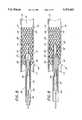
- FIG. 1is a cross sectional view of an embodiment of the stent of the present invention positioned within a body lumen.
- FIG. 2is an end view of the embodiment of the stent of the present invention positioned within a body lumen as in FIG. 1.
- FIG. 3is a cross sectional view of another embodiment of the stent of the present invention positioned within a body lumen.
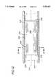
- FIG. 4is a partial perspective view of an embodiment of the extraction catheter of the present invention having two expandable extraction halos in an expanded position.
- FIG. 5is a partial perspective view of the embodiment of the extraction catheter illustrated in FIG. 4 with the expandable extraction halos in the retracted position.
- FIG. 6is an end view taken through the line 6--6 of the extraction catheter of FIG. 5.
- FIG. 7is a side elevational cross sectional view of the catheter illustrated in FIG. 4, in the contracted position.
- FIG. 8is an elevational cross sectional view of the catheter of FIG. 7, positioned within an implanted stent.
- FIG. 9is a cross sectional elevational view as in
- FIG. 8with the inner tube distally extended.
- FIG. 10is a cross sectional elevational view as in FIG. 9, with the guidewire extended.
- FIG. 11is an elevational cross sectional view as in FIG. 10, with the proximal and distal engagement structures engaged, and the stent radially reduced.
- FIG. 12is a partial cross sectional view of an elastomeric tube embodiment of the stent of the present invention positioned within a body lumen.
- FIG. 13is cross-sectional view of the stent of the present invention taken through the line 13--13 of the stent of FIG. 12.
- FIG. 14is a cross-sectional view of an engagement element taken through the line 14--14 of FIG. 13.
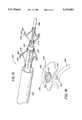
- FIG. 15is a partial perspective view of an embodiment of the retrieval catheter of the present invention having four proximal spring elements and four distal spring elements.
- FIG. 16is an elevational partial perspective view of an alternate embodiment of an engagement element and corresponding embodiment of a spring element with attached contact surface.
- Stent 10is illustrated in its expanded position at a treatment location adjacent vascular wall 12 in an artery 13, in accordance with one aspect of the present invention.
- Stent 10comprises a generally tubular body 14 with a central lumen 15 extending between proximal end 16 and distal end 18.
- the stent 10can be balloon expandable, self expanding, thermally expandable or expandable by other means and still incorporate the inventions described herein.
- Metal mesh or woven walled stentsare well suited for expansion on a dilation catheter, as discussed infra.
- tubular stents formed from flexible non-metal materialssuch as elastomeric polymers or rubber (latex) can also be radially reduced by axial elongation in accordance with the present invention.
- Polymeric stentscan be provided with relatively fluid impenetrable walls, or porous walls such as to allow drug delivery, as will be apparent to one of skill in the art.
- stent 10has a lattice structure 20 with a plurality of openings 22 therethrough. This design facilitates radial expansion of tubular stent 10 from a first insertion diameter to a second expanded diameter, and radial reduction by elongating the tubular stent 10 along its longitudinal axis.
- the latticecomprises a braided or woven wire mesh.
- mesh woven from 0.005 inch diameter stainless steel or other deformable (malleable) material, such as gold wire in a weave pattern much like the outer conductor of coaxial electrical cablemay be used.
- a lattice patterncan be stamped or cut from flat sheet stock and rolled and soldered or brazed to produce an unexpanded stent.
- a variety of lattice patternscan be devised which meet the functional criteria described herein. Therefore, the illustrated lattice structure 20 should be considered exemplary only.
- stent 10is made of a design and/or material which is sufficiently strong to maintain the expanded diameter of the stent 10 against compressive forces exerted by the vascular wall 12.
- the materialshould be sufficiently malleable or loosely woven to reversibly expand and contract between the insertion diameter and the desired expanded diameter.
- Stent 10is preferably also made from materials which have at least a biocompatible exterior surface. Most preferably, the stent comprises a homogeneous material throughout, such as stainless steel or gold. Use of a radiopaque material or marker facilitates proper placement and removal.
- Biocompatibilitycan be enhanced by applying any of a variety of coatings to the surfaces 24 of the stent 10.
- the processes for applying a biocompatible coatingare known in the art.
- other coatingssuch as to promote or inhibit tissue ingrowth or inhibit thrombus formation, can also be applied as will be understood by one of skill in the art.
- the interior and exterior walls of stent 10are enclosed in a thin polymeric envelope 25.
- the interior portion of polymeric envelope 25is illustrated in cut away fashion in FIG. 1 and FIG. 13 and is deleted from the remaining Figures for clarity.
- the exterior portion of envelope 25is illustrated in FIGS. 1 and 2.
- Suitable envelope materialsinclude elastic materials such as latex and others that can be readily selected by one of skill in the art.
- Polyethylene or PET or other envelopes with or without an outer silicone or PTFE coatingcan be preformed with ridges or indentations on the interior surface to accommodate the projections 26.
- biocompatible materialswhich can tolerate expansion of the stent between the insertion diameter and expanded diameter can be used.
- the envelopemay be produced, for example, by inserting the stent into a preformed tubular envelope having one open end and sealing the envelope closed, or other techniques within the skill in the art.
- One such envelopecan be readily formed by inserting a first end of a tubular sleeve back inside of the tube and advancing it through the tube to the second end of the tubular sleeve. After insertion of the stent, the open end of the envelope can be sealed in any of a variety of ways known in the art.
- the exterior surface of the envelope which will contact the arterial wallis optionally made porous to enable the release of drugs from the envelope and/or stent 10 to the treatment site.
- the stentpermits drug delivery directly to a preselected site in a body lumen.
- the envelopecan act as a reservoir and be filled with a medication prior to implantation at the desired treatment location.
- the drugsare released when the stent 10 is expanded to its implanted diameter.
- the stentcan be provided with a solid drug carrier such as an impregnated porous solid wall or sponge for timed drug delivery.
- the polymeric cover on stent 10can similarly take the form of an enclosed envelope such as a tube within a tube which is heat sealed, solvent bonded or otherwise secured at each end.
- a tubular sheath surrounding only the outer circumference of stent 10will also accomplish the adhesion inhibition discussed infra.
- the tubular sheathcan be made from an elastic material such as latex, which will expand with the stent, or of a relatively inelastic material such as PET or other conventional balloon material which is preformed in the size of the implanted (expanded) stent.
- the polymeric coveradditionally covers the inner wall of the stent to also minimize flow turbulence or thrombus formation sites.
- Angioplastywhether performed by balloon, lasers or atherectomy devices creates a wound in the enlarged arterial wall.
- healing actionstarts immediately and may continue for a week or more.
- the healing actionincludes thrombi, cell formation and scar tissue.
- One purpose of the temporary stent 10is to modify the healing response to prevent re-occlusion of the artery (restenosis).
- a smooth polymeric cover or envelope around the meshis, in part, to prevent thrombus and scar cell formations from penetrating the interstices of the mesh, which would cause trauma upon removal of the stent 10.
- Use of the smooth cover disclosed hereinpromotes formation of a thin film covering the arterial wound and adhering as little as possible to the stent.
- the expanded pores for drug deliveryshould be small enough to minimize or prevent cell penetration, but large enough for drug delivery.
- liquid drug moleculesare usually much smaller than cells, potentially by as much as 1:1000.
- the stentis longer than the treated wound, thus preventing healing cells from moving around the end edges of the stent.
- the wall thickness of the stent 10may vary depending on the required application.
- the wall thickness of the stent 10should be sufficient when the stent 10 is in its expanded configuration to withstand radially inwardly directed force exerted by the vascular wall 12.
- the wallshould be sufficiently thin for a selected construction material to enable the stent 10 to be expanded by a conventional balloon catheter and contracted by an extraction catheter of the present invention.
- the stentshould exert sufficient pressure against the arterial wall to minimize or prevent migration away from the treatment site.
- the optimal balance of wire diameter and tightness of the weavecan be determined through routine experimentation by one of skill in the art.
- the wall thickness of the stent 10will be no more than about 0.015 inches and no less than about 0.005 inches for a woven wire stent made from stainless steel and having an unexpanded diameter of about 0.030 inches. In some cases a wall thickness less than about 0.005 inches may be desired. In addition, some instances may require a wall thickness of greater than about 0.015 inches, but may be difficult to radially contract for extraction.
- the wall thicknesswill generally be substantially uniform throughout the axial length of the stent 10, particularly in the case of woven wire stents. However, the wall thickness on the medial portion of the stent 10 may be different from the wall thickness at the proximal and/or distal ends 16, 18 of the stent 10, such as in the case of stamped or rolled stents, to affect the inflated configuration or strength profile of the stent.
- the insertion diameter and axial length of the stent 10will vary with the specific intended application. One skilled in the art will be readily able to choose the appropriate insertion diameter of the stent 10 depending on the diameter of the artery 13 to be treated and the maximum expandable diameter of the stent 10. The location of the treatment site and the desired percentage of restored flow will influence the necessary expansion characteristics of the stent.
- a typical stent 10is able to expand to at least about 300% of its insertion diameter and preferably, to as much as 400% or more of its insertion diameter.
- the clinicianwill choose a stent such that the stent 10 will be expanded to an implanted diameter which is between about 200% and 500% of the insertion diameter.
- the implanted diameterwill typically approximate the native diameter in the absence of the stenosis, which is on the order of about 2.5 mm to about 3.5 mm in the coronary artery.
- Peripheral arteriesgenerally have a native interior diameter within the range of from about 3 mm to about 10 mm (iliac) with the femoral at about 6 mm.
- the axial length of the stent 10 for coronary artery applicationswill typically be in the range from about 1 cm to about 3 cm. In peripheral vascular applications, stent lengths within the range of from about 1 cm to about 5 cm are to be expected in most cases, although the length may vary considerably from case to case depending upon the anatomy and the underlying etiology at the treatment site. It may also be desired to implant two or more short stents end to end such as in a remote stenosis which may be difficult to reach with a longer stent due to its relatively low bendability, or to permit continued perfusion through a branch artery exiting between two adjacent stents.
- the stent 10 of the present inventionincludes at least a proximal (FIG. 3) and in another embodiment also a distal (FIG. 1) engagement member spaced axially apart along the length thereof.
- the engagement memberscan assume any of a variety of physical configurations, so long as they enable the removal catheter to accomplish an axial elongation of the implanted stent.
- the engagement membersare elastically deformable radially outwardly, or otherwise provided with smooth surfaces so that they will not puncture a dilatation balloon.
- One example of a shape of the engagement members of the present inventionis a hook like shape as illustrated in FIG. 1.
- other applicable shapes of the engagement membersmay be chosen by one skilled in the art.
- any of a variety of rigid or moveable radially inwardly biased ramp structurescan also readily be used.
- Extensions of integral wire segments in a woven wire stentcan also be used as will be apparent to one of skill in the art.
- Engagement memberssuch as projections 26, are secured to the lattice structure 20 of the stent 10 with sufficient structural integrity to enable a sufficient axially extending force to be applied to the engagement members to stretch the length of the stent 10 without causing the engagement members to disengage from the stent 10.
- Engagement members, such as projections 26,may be integrally formed with the lattice structure 20, or they may be secured to the lattice using attachment techniques known in the art, such as brazing, soldering, solvent bonding, spot welding, or others, as appropriate for the construction material of the stent.
- the opposing sets of engagement memberscomprise one or more inwardly extending projections 26 at each axial end thereof.
- the opposing sets of engagement memberscomprise one or more inwardly extending projections 26 at each axial end thereof.
- two to five or more inwardly extending projections 26are positioned on each end of stent 10.
- the projections 26are generally radially symmetrically positioned about the circumference of the stent. See FIG. 2.
- alternative positioning of the projections 26are possible as will be recognized by one skilled in the art.
- More than one projection 26 at each endare generally desired. Greater than about five projections 26 per end may also be used. However, much more than about three or four projections 26 may undesirably interfere with the effective flow area of the arterial lumen or produce undesirable turbulence in the blood flow.
- each of the proximal and distal ends 16, 18 of the stent 10has the identical number of radially inwardly extending projections 26.
- FIG. 3illustrates an alternative embodiment of the cardiovascular stent 30, implanted against the vascular wall 12 of an artery 13. Radially inwardly extending projections 26 are only provided on the proximal end 16 of the stent 30.
- proximal and distalshall be determined with reference to the removal catheter, and not necessarily to the arterial anatomy.
- the cardiovascular stent 30has a generally tubular body as described above. However, the stent 30 is seated on the dilatation balloon such that the proximal end 16 of the stent 30 extends proximally beyond the proximal end of the balloon. When the balloon is inflated, the proximal end 16 of the stent 30 is not fully expanded, thus resulting in the smaller diameter at proximal end 16 as illustrated in FIG. 3.
- Alternative means for providing a reduced proximal diametercan also be used, such as providing a stent with a nonexpandable proximal section, greater wall thickness, or others that can readily be devised by one of skill in the art.
- the proximal end of the tubular stenthas a sufficiently reduced diameter that it inclines radially inwardly away from the vascular wall.
- the diameter of the installed stent at its most proximal endis sufficiently small that it will fit within the central lumen of a tubular catheter, such as will be described infra.
- the distal end of the central lumen of the removal catheteris flared radially outwardly to more easily receive the stent as will be appreciated by one of skill in the art.
- Removal of the stentis accomplished by engaging the proximal end of the stent within the removal catheter and grasping the projections 26 as will be discussed. Projections 26 are pulled axially in the proximal direction, causing a radial reduction in the size of the stent at the point the stent enters the smaller diameter of the lumen in the tubular extraction catheter.
- the extraction catheteris preferably gradually advanced distally over the entire length of the stent so that the stent is forced to a reduced diameter to fit within the catheter. The catheter and stent can then be removed from the vascular site.
- a second aspect of the present inventioncomprises an extraction catheter 50 for use with the cardiovascular stent 10 of the present invention. See FIGS. 4-7.
- the catheter 50preferably includes an elongate tubular body 52 having a contact surface 54 for contacting the proximal engagement structure on the stent.
- a moveable membersuch as a guidewire 56 is provided with an opposing contact surface 58 for contacting the distal engagement members of the stent 10.
- the guidewire 56travels in an axial direction away from the tubular body 52, the stretching force applied to the stent 10 will cause the stent 10 to become elongated, and simultaneously reduced in diameter for removal.
- an outer tubular body 60is also provided to assist in both the placement of the catheter, and atraumatic removal of the contracted stent.
- the contact surface 54 on one embodiment of the extraction catheter 50is provided on the proximal surface of an engagement structure such as a radially outwardly extending annular ring or halo 62 for engaging the proximal engagement members of the stent 10.
- Halo 62is preferably supported by one or more spokes 63 which may be similar to spokes 68 discussed infra.
- any of a variety of alternative support structures for supporting a contact surface 54such as an annular flange, plurality of radial spokes or others can be used as will be apparent to one of skill in the art.
- the halo 62 or a radial flangecan extend less than the entire circumference of the catheter.
- a plurality of discrete structuressuch as ramps which incline radially outwardly in the proximal direction and are resiliently deflectable can provide a useful ratchet like locking structure.
- the annular halo 62 or flangeis preferred because of manufacturing convenience and because it does not require any particular rotational alignment.
- the flangeis preferably deflectable in the proximal direction yet sufficiently resistant to distal pressure to permit insertion into the stent and also accomplish the desired result as will become apparent.
- the halo 62 or flangeis preferably formed from a high tensile strength, soft and easily bondable material such as nylon. Additional construction parameter are discussed infra.
- the annular halo 62can extend from about 0.010 inches to about 0.050 inches or greater beyond the outer radius of the tubular body 52, depending upon the diameter of the intended artery and diameter of the catheter.
- An elongate central lumen 64extends throughout the tubular body 52 for axially movably receiving an extraction guidewire 56.
- the extraction guidewire 56generally comprises a flexible central rod or spring coil provided with a second annular halo 66 suspended from the guidewire 56 by a series of spokes 68.
- the guidewire 56may comprise any of a variety of guidewires known in the art. Most preferably, guidewire 56 comprises a steerable guidewire such as any of those disclosed in U.S. Pat. No. 5,108,368 to Hammerslag et al. and entitled “Steerable Medical Device", the disclosure of which is incorporated herein by reference.
- the annular halo 66 and spokes 68are flexible to accommodate bending or compression to fit within the lumen 64 as illustrated in FIG. 5. Therefore, the material which makes up these elements is preferably sufficiently elastic to return to its expanded shape after being stored in its compressed state within the lumen 64. However, the material must also be strong enough to transfer sufficient longitudinal elongation force to the stent 10.
- the halo 62, 66 and the spokes 63, 68 of the extraction guidewire 56can be made from metal wire, a polymeric material such as nylon or the like.
- the same material or different materialmay be used to make the halo 62, 66 and the spokes 63, 68, as long as the material chosen for each meets the above criteria.
- the halois formed from a soldered ring of stranded wire such as seven strands of 0.0005 inch diameter stainless steel wire having a total diameter of about 0.0015 inch, obtainable from Fort Wayne Metals, Fort Wayne, IN.
- the stock of halo 62, 66is between about 0.001 inches and 0.005 inches in diameter.
- a thickness less than about 0.001 inchescan be used, however, the ring may not be strong enough to transfer the required force to elongate the stent 10.
- thicknesses greater than about 0.005 inchesmay be used. However, if the thickness becomes too large, undesired conditions may occur such as inadequate flexibility during the implantation or extraction procedure.
- the spokes 68are made of spring hardness stainless steel. Spokes 68 are of sufficient length and resilience to bias the halo 66 against the interior surface of the stent such that the contact surface 58 of the halo 66 contacts the distal projections 26 of the stent 10 when the halo 66 is in the extended position.
- the spokes 68can be anywhere from 0.010 inches to 0100 inches or more in length depending on the diameter of the stent 10 and the length of the projections 26.
- the spokes 63, 68are preferably between 0.020 and 0.050 inches in length for use with a typical 0.130 inch inflated diameter coronary stent 10.
- the halo 66 and spokes 68 of the guidewire 56are bent into a radially restricted position when the guidewire 56 is positioned within the central lumen 64.
- the halo 66is designed such that it can be radially compressed to be stored within the lumen 64 of the tubular body 52, and then automatically expand radially outwardly upon axial displacement beyond the distal end of central lumen 64.
- each of the halos 62 and 66can be reduced in radial diameter by bending into a sine wave configuration which will permit the diameter of both the tube 52 and the outer tube 60 to be minimized.
- the halos 62 and 66can be collapsed radially inwardly with the spokes 63 and 68 inclining in either the proximal or distal direction.
- a preferred packing arrangementis disclosed.
- the spokes 68 on guidewire 56are inclined in the proximal direction, while spokes 63 on inner tube 52 are inclined in a distal direction. This configuration has been determined to conveniently facilitate a radially inwardly directed force upon the application of axial stretching force on the stent, as will apparent to one of skill in the art.
- halos 62, 66 and spokes 63, 68are possible which will provide a radial outward bias.
- the annular halos 62, 66 and spokes 63, 68 designshould be considered as only one of a number of possible embodiments which would achieve the above described function.
- the stent 10is inserted into an artery 13 using a conventional balloon catheter insertion procedure.
- a stent 10is positioned on a deflated dilatation balloon.
- a stent 10 of the type illustrated in FIG. 1is positioned on the balloon such that an equal force will be distributed throughout the length of the stent 10 when the balloon is inflated.
- the stent 10may be gently pulled in a longitudinal direction causing the diameter of the stent 10 to contract and remain in contact with the deflated balloon.
- the balloonis then navigated distally and positioned at the treatment site using procedures well known in the art.
- the balloonis inflated, thereby expanding the stent 10 radially outwardly until it contacts either a previously dilated, or presently stenosed wall.
- the balloonmay be further expanded to force the stent 10 and a stenosed vascular wall 12 until it reaches a desired enlarged diameter.
- a balloonmay be used which has two or more annular recesses to accommodate projection 26. Balloons made of PET are particularly suitable for this kind of construction.
- the stentcan be inserted following a dilatation, or the stent can be inserted on the dilatation balloon to simultaneously accomplish dilatation and stent implantation. If the elastic jacket of stent 10 has been impregnated with a drug, the expansion of the stent stretches the pores of the elastic jacket and commences or enhances the delivery of drugs to the treatment site on the vascular wall 12.
- the balloonis thereafter deflated, and removed from the body using conventional techniques.
- the stent 10remains in its expanded position due to the design of the lattice structure 20 of the stent 10.
- FIGS. 8-11An exemplary but nonexclusive procedure used to extract a stent 10 of the type illustrated in FIGS. 1-2 with an extraction catheter 50 as illustrated in FIGS. 4-7 is described below with reference to FIGS. 8-11.
- the extraction catheter 50is navigated to a location proximal to the stent 10 using standard angioplasty catheter advancement procedures.
- the distal end 61 of outer tube 60is advanced into the lumen 15 of stent 10, and positioned between the proximal and distal sets of projections 26.
- either of the guidewire 56 or the inner tube 52is advanced distally into the stent.
- FIG. 9there is illustrated an embodiment of the method in which the inner tube 52 is advanced a sufficient distance into the stent so that the halo 62 is released from the outer tube 60.
- Halo 62expands radially outwardly under the bias exerted by the halo 62 and spokes 63.
- the guidewire 56is advanced a sufficient distance distally so that the halo 66 is released from the distal end of the inner tube 52.
- Halo 66similarly expands radially outwardly to intercept the distal engagement structures on the stent 10.
- the halo 62is thereafter seated in the proximal projections 26 as illustrated in FIGS. 10 and 11, and the halo 66 is seated in the distal projections 26.
- the guidewire 56is then advanced distally with respect to the inner tube 52, thereby axially elongating the tubular stent 10 and reducing its cross sectional area. See FIG. 11.
- the very action of pulling on the spokes in the direction opposite in which they are deflectedcreates an inward pull on the halo, and hence the stent, aiding the contraction effect on the stent through elongation.
- Axial elongationis continued until the diameter of the stent 10 is sufficiently reduced for removal from the vascular site.
- the tubular body 52 with the stent engaged thereonis advanced into the distal end of the outer tube 60 to minimize trauma to the vascular intima during withdrawal of the catheter from the body.
- the inner tube 52can be provided with two or more radially outwardly biased halos such as halo 62, for engaging multiple sets of projections 26 within the tubular lumen of the stent 10. This may be desirable to assist in the collapse of particularly long stents.
- a third set of projections 26is provided midway between the proximal projections and the distal projection.
- a second halo 62is provided on the inner tube 52, and spaced apart from the first halo 62, so that each of the two halos 62 on the inner tube 52 and the halo 66 on the guidewire 56 is adapted to engage a unique set projections 26 on the stent 10. In this manner, a radially inwardly directed force can be generated at a midpoint in the stent, to facilitate radial collapse.
- the removal catheter for use with the stent illustrated in FIG. 3comprises an outer tubular body 60 as illustrated in FIG. 4, together with a guidewire 56 having an annular halo 66 thereon.
- the inner tube 52 and the halo 62is not necessary for this embodiment.
- the implanted stent of FIG. 3is approached for removal from the proximal end 16 thereof.
- the outer tube 60is advanced distally so that the distal end of the outer tube 60 surrounds the proximal tapered portion of the stent 30.
- halo 66travels through the opening in the proximal end 16 of the stent 30, and beyond projections 26.
- Distal travel of the halo 66 beyond projections 26can be accomplished either by a resilient deflection of the halo 66 and/or projection 26, or by the use of an inner tube such as 52, however which is not provided with a halo 62.
- proximal traction on the guidewire 56will seat the halo 66 within projections 26, and tend to pull the stent into the outer tube 60.
- Continued traction on the guidewire 56 with respect to the outer tube 60will draw the stent within the outer tube 60, by a radial compression of the stent as it enters the distal opening on outer tube 60.
- Trauma to the vascular intimacan be minimized by gradually advancing the outer tube 60 in a distal direction while maintaining traction on the guidewire 56 such that the expanded stent is not displaced axially within the artery.
- the removal catheter disclosed hereincan also function as an insertion catheter, such as for use with self expandable stents.
- stentsformed from flexible non-metal materials such as elastomeric polymers or rubber, such as latex, are installed onto the removal catheter prior to insertion into the patient.
- the removal catheteris manipulated to axially elongate the tubular stent, thereby producing a radial reduction thereof.
- the stentmay further be withdrawn within the tube 60, for positioning within the patient.
- annular halos 62, 66 or corresponding structure of the removal toolare withdrawn within the tubular body, so that they may be proximally withdrawn from within the implanted stent.
- guidewire 56may be proximally withdrawn into inner tube 52, and thereafter inner tube 52 is proximally withdrawn to bring halo 62 within outer tube 60.
- the distal end of the removal catheter 50can be withdrawn from the implanted stent without engaging the proximal engagement members thereof.
- the same stentcan thereafter removed, such as in a subsequent procedure, in accordance with the methods described previously.
- a radially expandable and compressible elastomeric stentReferring now to FIGS. 12-14, stent 510 is illustrated in its expanded position at a treatment location adjacent vascular wall 512 in an artery 513.
- Stent 510comprises a generally tubular body 514 with a central lumen 515 extending between proximal end 516 and distal end 518.
- the stent 510comprises a material which allows radial expansion of tubular stent 510 from a first insertion diameter to a second expanded diameter, and radial reduction by elongating the tubular stent 510 along its longitudinal axis.
- the native configuration of the stentis its second, expanded diameter and insertion is accomplished by axial stretching as will be discussed. In this manner, the stent tends to seek its desired implanted configuration.
- Suitable materialsinclude elastomeric polymers or natural rubber (latex).
- One preferred materialis Krayton (TM), available from Western Rubber and Supply (Haywood, Calif).
- Polymeric stentscan be provided with relatively fluid impenetrable walls, or porous walls such as to allow drug delivery, as will be apparent to one of skill in the art.
- stents that are balloon expandable, thermally expandable or expandable by other meansmay still incorporate the catheters and engagement structures for retrieval described herein.
- stent 510is made of a design and material which is sufficiently strong to maintain the expanded diameter of the stent 510 against compressive forces exerted by the vascular wall 512. At the same time, the material should be sufficiently malleable or elastic to reversibly expand and contract between the insertion diameter and the desired expanded diameter. Stent 510 is preferably also made from materials which have at least a biocompatible exterior surface.
- Biocompatibilitycan be enhanced by applying any of a variety of coatings to the surfaces 524 of the stent 510.
- other coatings or manufacturing techniquesmay promote or inhibit tissue adhesion, inhibit thrombus formation or provide smooth surfaces, as will be understood by one of skill in the art.
- both the interior and exterior surfaces of stent 510are coated to impart properties discussed above.
- the embodiment illustrated in FIG. 13shows a single interior coating 527 and a single exterior coating 529. Alternately, only the interior or exterior surface of stent 510 alone could be coated, or multiple coats of the same or different material could be used on the interior or exterior surface of stent 510. No coating at all may be desired for certain applications.
- Suitable coating materialsinclude elastic materials such as polyethylene or PET or other materials that can be readily selected by one of skill in the art. In general, any biocompatible material which can tolerate expansion of the stent between the insertion diameter and treatment diameter can be used. However, a non-biocompatible material may be used as one of multiple coatings where the non-biocompatible material is sandwiched between other layers, such that the material is not exposed to body fluids or tissues.
- Coating materialmay be applied to individual surfaces by painting, bonding with a suitable adhesive or mechanically fixing as appropriate to the material of the coating and material comprising the bulk of the stent body as will be appreciated by one with skill in the art.
- internal and external coatingsmay be applied by inserting tubular wall 514 into an envelope or sleeve of suitable material as is discussed above.
- the stentis dip molded over a highly polished internal mandrel to produce a smooth walled interior layer.
- the exterior coating 529 which will contact the arterial wallis optionally made porous to enable the release of drugs to the treatment site.
- the stentpermits drug delivery directly to a preselected site in a body lumen.
- the provision of a smooth coating on the exterior surface of stent 510serves, in part, to inhibit scar tissue or normal epithelial cell proliferation from penetrating the aperture in the engagement elements, discussed below.
- the wall thickness of the stent 510will vary depending on the required application.
- the wall thickness of the stent 510should be sufficient when the stent 510 is in its expanded configuration to withstand radially inwardly directed force exerted by the vascular wall 512.
- the wallshould be sufficiently thin for a selected construction material to enable the stent 510 to self-expand and to be contracted by an extraction catheter of the present invention.
- the stentshould exert sufficient pressure against the arterial wall to minimize or prevent migration away from the treatment site.
- the optimal balance of expanded outer diameter and expanded wall thicknesscan be determined through routine experimentation by one of skill in the art.
- the unexpanded wall thickness of a latex stent 510 for coronary artery applicationsis preferably between about 0.05 and about 4 mm. More preferably, stent 510 has an unexpanded wall thickness between about 0.2 and about 2 mm. In some cases a wall thickness less than about 0.05 mm may be desired, depending upon the etiology of the condition being treated. In addition, some instances may require a wall thickness of greater than about 4 mm.
- the wall thicknesswill generally be substantially uniform throughout the axial length of the stent 510. However, the wall thickness on the medial portion of the stent 510 may be different from the wall thickness at the proximal 516 and/or distal ends 518 of the stent 510, such as in the case of stamped or rolled stents, to affect the expanded configuration or strength profile of the stent.
- the expanded outer diameter and axial length of the stent 510will vary with the specific intended application.
- One skilled in the artwill be readily able to choose the appropriate insertion diameter of the stent 510 depending on the diameter of the artery 513 to be treated and the maximum expandable diameter of the stent 510.
- the stentis longer than the treated wound, thus minimizing proliferating cells at the treatment site from migrating around the proximal end 516 and distal end 518 of the stent.
- a typical stent 510is able to expand to at least about 200% of its insertion diameter and preferably, to as much as 500% or more of its insertion diameter.
- the clinicianwill choose a stent such that the stent 510 will be expanded to an implanted diameter which is between about 300% and 400% of the insertion diameter.
- the implanted diameterwill typically approximate the native diameter in the absence of the stenosis, which is on the order of about 0.10 inches to about 0.14 inches in the coronary artery.
- stent 510has an insertion (reduced) outer diameter between about 0.03 and 0.20 inches for a stent comprising latex. More preferably, stent 510 has an unexpanded outer diameter between about 0.04 and 0.10 inches. Both ideal outer diameter and ideal wall thickness will be determined by the inherent expandability of the material used and the size of the blood vessel to which the stent 510 is to be applied, as will be apparent to one skilled in the art. Therefore, the dimensions given herein should be considered exemplary only.
- the clinicianwill select a stent 510 having an axial length that will sufficiently support the treatment site on the vascular wall 512.
- the axial length of the stent 510will typically be in the range from about 0.25 inches to about 7.50 inches.
- the stentis within the range of from about 0.5 inches to about 2.0 inches.
- stent lengthswithin the range of from about 2.5 inches to about 12.5 inches may be expected in most cases, although the length may vary considerably from case to case depending upon the anatomy and the underlying etiology at the treatment site. It may also be desired to implant two or more short stents end to end such as in a remote stenosis which may be difficult to reach with a longer stent due to its relatively low bendability, or to permit continued perfusion through a branch artery exiting between two adjacent stents.
- stent 510 of the present inventionincludes at least one proximal and one distal engagement element 526 spaced axially apart along the length thereof.
- the engagement elementscan assume any of a variety of configurations so long as they enable the retrieval catheter to accomplish an axial elongation of the implanted stent. Suitable configurations include holes and/or slits extending through the entire wall thickness of stent 510. Alternatively, recesses extending partially through the wall thickness of stent 510 or through the entire wall thickness of stent 510 excluding at least the most external coating may also be used.
- the engagement elementdoes not extend completely through an exterior layer 529 adjacent tubular wall 514 to provide the smoothest possible surface in contact with the vascular wall 512.
- Scar tissue penetration of the engagement elementscan undesirably cause trauma upon removal of the stent 510.
- engagement elementsmay be formed by incorporating one or more proximal and distal O-rings into the inner surface of the stent wall, where the O-rings are segmented to allow for radial contraction and expansion of the stent.
- FIGS. 12-14One example of a configuration for an engagement element 526 of the present invention is illustrated in FIGS. 12-14.
- Other suitable shapes of the engagement elementsmay be chosen by one skilled in the art including, for example, round, oval, square and key hole shaped.
- the engagement element 526 illustrated in FIG. 12comprises an aperture 530 extending through the wall of stent 510, including any coating on the inner surface of stent 510.
- the engagement element 526may or may not extend entirely through a layer on the external surface of stent 510, and is illustrated as not extending through an outer layer 529 on the external surface of stent 510.
- the illustrated engagement element 526 in FIGS. 12-14further comprises a force dispersing structure 528 such as an annular flange surrounding at least part of the boundary of the aperture.
- Suitable force dispersing structuresinclude metal or synthetic flanges, integral thickening of the tubular wall 514 and chemically, thermally or mechanically altered borders of the aperture which impart force dispersing properties. These force dispersing properties desirably decrease the incidence of tearing tubular wall 514 during axial traction on the engagement element during insertion and/or retrieval of stent 510.
- the configuration of the engagement element 526, with or without force dispersing structures 528is equally suited to stents that are not self-expanding such as embodiments discussed above.
- the cross-sectional configuration of the engagement element 526is best understood by reference to FIG. 14.
- the engagement element 526comprises a generally grommet-shaped body having first and second opposing annular flanges 528 and 538 extending radially outwardly therefrom. When installed in a tubular stent 510, the opposing flanges 528 and 538 compress a portion of the wall of the stent generally as illustrated in FIG. 14, to both secure the engagement element 526 to the stent 510 and also to minimize the outer profile of the installed engagement element 526.
- the engagement element 526is further provided with a central aperture 530 for receiving the installation and removal tool.
- the wall 539 of aperture 530is provided with a surface having a radially inwardly directed channel or concavity, which may be annular as illustrated, or only on the contact surface, to removably receive a portion of the installation and removal tool. Engagement of the element 526 within the recess at wall 539 minimizes trauma to the vascular wall.
- engagement elements 526may be integrally formed with tubular body 514, or they may be drilled into or punched or otherwise mounted to the tubular body 514.
- Force dispersing structures 528may also be integrally formed with tubular body 514 or may constructed after formation of tubular body 514.
- the borders of engagement element 526may be chemically, thermally or mechanically altered to create the desired force dispersing properties.
- both engagement element 526 and force dispersing structures 528may be generated at the same time such as by means of a punch press to form a grommet around a hole in tubular wall 514, such as is illustrated in FIGS. 12 and 13.
- the engagement elementcomprises a metal, and, more preferably, a radiopaque and biocompatible metal such as gold.
- the number of engagement elementswill vary with the design of stent 510 but should include at least one proximal and at least one distal engagement element. More preferably, the design of stent 510 will include two to five proximal and two to five distal engagement elements. Most preferably, the design of stent 510 will include either three or four proximal, and either three or four distal engagement elements.
- radially symmetric spacing of multiple proximal and multiple distal engagement elements around the periphery of the stentwill distribute the axial forces during insertion and retrieval most effectively to prevent structural failure of the stent.
- radially asymmetric spacing between the proximal engagement elements as compared to the distal engagement elementswill allow the contact surfaces of the proximal engagement means of the insertion/retrieval catheter to engage only the proximal engagement elements and the contact surfaces of the distal engagement means of the insertion/retrieval catheter to engage only the distal engagement elements.
- the insertion/retrieval catheteris described in greater detail below.
- Inappropriate engagement of the distal engagement element of the catheter with the proximal engagement element of the stentcan also be minimized by having a different number of proximal engagement elements compared to the number of distal engagement elements, or by having different shaped proximal engagement elements from the shape of the distal engagement elements, and having corresponding configurations of the contact surfaces of the insertion/retrieval catheter. Further, combinations of asymmetric spacing, unequal numbers and/or dissimilar shapes can be used as will be readily apparent to one with skill in the art.
- the engagement elements 526 of stent 510may be constructed to serve as radiopaque markers to identify the position of the sent in vivo, and/or the position of the engagement elements themselves. This can be accomplished by impregnating the borders of the engagement element with radiopaque substance or by forming the force dispersing structure 528 or the entire engagement element from radiopaque material, among other techniques known to those with skill in the art.
- the preferred embodimentis provided with four symmetrically spaced, elongated proximal engagement elements and four symmetrically spaced, elongated distal engagement elements.
- the central aperture in the engagement elementis in the shape of an oval, having a narrow dimension of about 0.010 inches, a length dimension of about 0.075, and oriented with the long axis of the oval extending generally parallel to the longitudinal axis of the stent. This configuration is intended to be exemplary only, and round or other aperture configurations may alternatively be used.
- Another aspect of the present inventioncomprises an insertion/retrieval catheter 550 for use with the cardiovascular stent 510 of the present invention.
- One embodiment of the catheter 550is illustrated in FIG. 15.
- the catheter 550preferably includes an inner tubular body 552 having one or more contact surfaces 554 for contacting the proximal engagement elements of the stent 510.
- the tubular body 552can comprise a segment of hypotube, an extrusion, or a length of coiled spring wire coated with Teflon®, a PVC sleeve, or other material to inhibit axial expansion under the pulling force necessarily exerted during operation of the catheter as will be apparent.
- a central support 556such as a guidewire or tubular body is provided with one or more contact surface 558 for contacting the distal engagement elements of the stent 510.
- support 556is a tubular body such as a spring coil having an inside diameter of about 0.015 inches to permit over the wire positioning using a 0.014 inch diameter guidewire.
- the mechanism of operation of the catheter 550is similar to the mechanism of operation of the extraction catheter described in previous embodiments.
- the support 556is moved in an axial direction away from the tubular body 552.
- the axial stretching force applied to stent 510causes the stent 510 to become elongated and simultaneously reduced in diameter to allow for insertion into or retrieval from a vascular site.
- an outer tubular body 560is also provided to assist in both the placement of the catheter, and atraumatic removal of the contracted stent.
- contact surfaces 554are mounted on spring elements 566 and contact surfaces 558 are mounted on spring elements 568.
- Each spring element 566comprises a spring wire or ribbon attached such as by soldering to the tube 552 and extending radially outwardly from the tube 552 in an inclined manner towards the contact surface 554.
- the contact surface 554is disposed at the peak of a generally proximally facing curve or hook-shaped segment of spring element 566. In this manner, contact surface 554 can be positioned within aperture 530 of the engagement element 526, and, in particular, within the concavity or channel formed on the wall 539 of aperture 530.
- Spring element 566extends distally from contact surface 554 along a radially inwardly inclined ramp 570.
- Ramp 570facilitates introduction of the spring element 566 into the central lumen 515 of a tubular stent.
- the distal end of spring element 566is preferably connected such as by soldering to an annular ring 572 which is axially movably positioned over tubular body 552.
- annular ring 572which is axially movably positioned over tubular body 552.
- each of the remaining three spring elementsare similarly configured and connected to annular ring 572. In this manner, radial inward compression of the ramp 570 causes the four spring elements to move in unison, as the annular ring 572 travels axially along tubular body 552.
- each spring element 568is connected at its proximal end to an annular ring 574, axially movably disposed over the support 556.
- the spring element 568inclines radially outwardly from the point of attachment to annular ring 574, towards the contact surface 558.
- the spring element 568preferably inclines radially outwardly to a point 576 which is at a maximum distance from the support 566, and then inclines slightly radially inwardly before reaching contact surface 558.
- support 556can alternatively comprise a tubular structure, to permit "over the wire” positioning of the catheter over a conventional guidewire.
- the contact surfaces 554 and 558 and the spring elements 566 and 568comprise any of a number of materials as will be appreciated by those with skill in the art. These include a variety of metals and polymeric materials.
- the spring elements 566 and 568should be flexible and impart a radially outwardly directed bias at the thicknesses used. Typical dimensions of the spring elements 566 and 568 comprising stainless steel ribbon are 0.004 inches wide and 0.0015 inches thick. Platinum or gold are also useful for their relative radiopacity. The exact dimensions, including length will depend upon the stent design and material, as will be appreciated by one with skill in the art.
- the spring elements 566 and 568are attached to tubular body 552 and guidewire 556, respectively, by a suitable adhesive, solder or by mechanical means.
- the guidewire 556, tube 552 and spring elements 568 and 566can be soldered or brazed.
- the contact surfaces 554 and 558can be similarly secured to the spring elements 566, 568. Alternately, contact surfaces 554 and 558 may be integrally formed with spring elements 566 and 568, respectively.
- the exact means of attachmentwill depend on the material used for the tubular body 552, the guidewire 556, the spring elements 566 and 568 and the contact surfaces 554 and 558.
- the contact surfaceshave a configuration such that they will engage the inner surface 539 on engagement elements 526 of stent 510.
- the engagement element 526comprises an aperture 530 and force dispersing flange 528.
- the aperture 530is further provided with a radially extending recess 531 to provide a keyhole type interfit with the catheter as will become apparent.
- Contact surface 554 on a spring element 566is configured to engage a stent have an engagement element as illustrated.
- the contact elementhas a generally mushroom shaped configuration to interlock within the recess 531.
- the radially outward end 540 of the contact surface 554is of such a dimension that it will fit into the engagement element only at the side 532.
- FIG. 14One embodiment of the retrieval catheter 550 for use with the stent 510 is illustrated in FIG. 14.
- the retrieval catheter 550comprises an outer tubular body 560, an inner tubular body 552 and a guidewire 556.
- the inner tubular body 552 and guidewire 556each have one or more contact surfaces and spring elements as discussed above.
- the implanted stent of FIG. 12is approached for removal from the proximal end 516 thereof.
- the outer tube 560is advanced distally until it is in the vicinity of the proximal end 516 of stent 510.
- the inner tubular body 552 and guidewire 556are thereafter advanced distally so that spring elements 566, 568 carrying the contact surfaces 554, 558 clear the outer tubular body 560.
- the contact surfaceswill move radially outward. Once moved radially outward, the contact surfaces 554, 558 are positioned within the stent until they engage the proximal and distal engagement elements 526, respectively.
- stent 510is withdrawn from the body directly, or it may first be withdrawn into the outer tubular body 560 to minimize intravascular trauma.
- the catheter 550can also be used for implantation of a tubular stent 510 at a preselected site in a body lumen.
- the stent 510can be manually mounted on the engagement surfaces 554 and 558 under direct visual observation, and axially elongated by manipulating the catheter to extend the guidewire 556 distally with respect to tube 552.
- a thumb screw type or other conventional handpiece affixed to the proximal end of the catheter 550can be utilized to accomplish this purpose.
- the catheter 550 having an axially extended tubular stent 510 thereonis then introduced percutaneously and advanced transluminally along the vessel in accordance with conventional techniques.
- the stentis positioned at the treatment site, generally under radioscopic visualization.
- engagement structures 526 and/or other components of the systemcan be constructed from a radiopaque material.
- the manipulatoris adjusted to permit the contact surfaces 554 and 558 to advance axially towards each other, thereby releasing the axially elongating tension on the tubular stent 510.
- the tubular stent 510resumes its initial, relatively expanded configuration against the vessel wall.
- the catheter 550may thereafter be removed from the treatment site in accordance with conventional catheter removal techniques.
Landscapes
- Health & Medical Sciences (AREA)
- Engineering & Computer Science (AREA)
- Biomedical Technology (AREA)
- Heart & Thoracic Surgery (AREA)
- Cardiology (AREA)
- Oral & Maxillofacial Surgery (AREA)
- Transplantation (AREA)
- Vascular Medicine (AREA)
- Life Sciences & Earth Sciences (AREA)
- Animal Behavior & Ethology (AREA)
- General Health & Medical Sciences (AREA)
- Public Health (AREA)
- Veterinary Medicine (AREA)
- Optics & Photonics (AREA)
- Physics & Mathematics (AREA)
- Media Introduction/Drainage Providing Device (AREA)
Abstract
Description
Claims (12)
Priority Applications (1)
| Application Number | Priority Date | Filing Date | Title |
|---|---|---|---|
| US08/201,632US5474563A (en) | 1993-03-25 | 1994-02-25 | Cardiovascular stent and retrieval apparatus |
Applications Claiming Priority (2)
| Application Number | Priority Date | Filing Date | Title |
|---|---|---|---|
| US3699593A | 1993-03-25 | 1993-03-25 | |
| US08/201,632US5474563A (en) | 1993-03-25 | 1994-02-25 | Cardiovascular stent and retrieval apparatus |
Related Parent Applications (1)
| Application Number | Title | Priority Date | Filing Date |
|---|---|---|---|
| US3699593AContinuation-In-Part | 1993-03-25 | 1993-03-25 |
Publications (1)
| Publication Number | Publication Date |
|---|---|
| US5474563Atrue US5474563A (en) | 1995-12-12 |
Family
ID=46248406
Family Applications (1)
| Application Number | Title | Priority Date | Filing Date |
|---|---|---|---|
| US08/201,632Expired - Fee RelatedUS5474563A (en) | 1993-03-25 | 1994-02-25 | Cardiovascular stent and retrieval apparatus |
Country Status (1)
| Country | Link |
|---|---|
| US (1) | US5474563A (en) |
Cited By (265)
| Publication number | Priority date | Publication date | Assignee | Title |
|---|---|---|---|---|
| US5624450A (en)* | 1994-09-27 | 1997-04-29 | Cordis Corporation | Stent removal |
| US5725547A (en)* | 1996-01-04 | 1998-03-10 | Chuter; Timothy A. M. | Corrugated stent |
| EP0829242A1 (en)* | 1996-08-19 | 1998-03-18 | Schneider (Europe) Ag | Removal device for an implanted endoprothesis |
| WO1998014224A3 (en)* | 1996-10-03 | 1998-07-02 | Scimed Life Systems Inc | Stent retrieval device |
| US5785715A (en)* | 1995-12-07 | 1998-07-28 | Schatz; Richard A. | Retrieval shuttle |
| US5824036A (en)* | 1995-09-29 | 1998-10-20 | Datascope Corp | Stent for intraluminal grafts and device and methods for delivering and assembling same |
| US5833699A (en)* | 1996-04-10 | 1998-11-10 | Chuter; Timothy A. M. | Extending ribbon stent |
| US5843167A (en)* | 1993-04-22 | 1998-12-01 | C. R. Bard, Inc. | Method and apparatus for recapture of hooked endoprosthesis |
| FR2765099A1 (en)* | 1997-06-25 | 1998-12-31 | Jean Noel Bernard | Apparatus for implanting or removing components, e.g endoprosthesis, through biological ducts |
| FR2765098A1 (en)* | 1997-06-25 | 1998-12-31 | Jean Noel Bernard | APPLIANCE FOR LAYING AND RECOVERING PARTS SUCH AS ENDOPROTHESES |
| US5868753A (en)* | 1995-11-13 | 1999-02-09 | Schatz; Richard A. | Stent retrieval catheter |
| US5876450A (en)* | 1997-05-09 | 1999-03-02 | Johlin, Jr.; Frederick C. | Stent for draining the pancreatic and biliary ducts and instrumentation for the placement thereof |
| WO1999034744A1 (en)* | 1998-01-09 | 1999-07-15 | Ethicon, Inc. | Suture buttress |
| US5928246A (en)* | 1997-10-15 | 1999-07-27 | Bsc Northwest Technology Center, Inc. | Stent securing catheter |
| US5935161A (en)* | 1993-11-04 | 1999-08-10 | C. R. Bard, Inc. | Non-migrating vascular prosthesis and minimally invasive placement system therefor |
| US5951586A (en)* | 1996-05-15 | 1999-09-14 | Medtronic, Inc. | Intraluminal stent |
| US5993482A (en)* | 1996-01-04 | 1999-11-30 | Endovascular Technologies, Inc. | Flat wire stent |
| US6027509A (en)* | 1996-10-03 | 2000-02-22 | Scimed Life Systems, Inc. | Stent retrieval device |
| US6086599A (en)* | 1999-02-08 | 2000-07-11 | The Regents Of The University Of California | Micro devices using shape memory polymer patches for mated connections |
| US6106531A (en)* | 1995-12-07 | 2000-08-22 | Schatz; Richard A. | Retrieval shuttle |
| WO2000042948A3 (en)* | 1999-01-22 | 2000-12-07 | Gore Enterprise Holdings Inc | Low profile stent and graft combination |
| US6162237A (en)* | 1999-04-19 | 2000-12-19 | Chan; Winston Kam Yew | Temporary intravascular stent for use in retrohepatic IVC or hepatic vein injury |
| US6187016B1 (en)* | 1999-09-14 | 2001-02-13 | Daniel G. Hedges | Stent retrieval device |
| US6277084B1 (en) | 1992-03-31 | 2001-08-21 | Boston Scientific Corporation | Ultrasonic medical device |
| US6287331B1 (en) | 1992-03-31 | 2001-09-11 | Boston Scientific Corporation | Tubular medical prosthesis |
| US6317615B1 (en) | 1999-04-19 | 2001-11-13 | Cardiac Pacemakers, Inc. | Method and system for reducing arterial restenosis in the presence of an intravascular stent |
| US6336937B1 (en)* | 1998-12-09 | 2002-01-08 | Gore Enterprise Holdings, Inc. | Multi-stage expandable stent-graft |
| US20020028712A1 (en)* | 2000-08-18 | 2002-03-07 | Sportstec, Inc. | Apparatuses and methods for playing a golf-type game |
| US6395017B1 (en)* | 1996-11-15 | 2002-05-28 | C. R. Bard, Inc. | Endoprosthesis delivery catheter with sequential stage control |
| US6398803B1 (en) | 1999-02-02 | 2002-06-04 | Impra, Inc., A Subsidiary Of C.R. Bard, Inc. | Partial encapsulation of stents |
| US20020082683A1 (en)* | 1997-08-01 | 2002-06-27 | Stinson Jonathan S. | Radiopaque markers for implantable prostheses |
| US6451025B1 (en)* | 1996-04-01 | 2002-09-17 | General Surgical Innovations, Inc. | Prosthesis and method for deployment within a body lumen |
| US6468301B1 (en) | 2000-03-27 | 2002-10-22 | Aga Medical Corporation | Repositionable and recapturable vascular stent/graft |
| US6488700B2 (en) | 1999-02-26 | 2002-12-03 | Vascular Architects, Inc. | Endoluminal prosthesis placing method |
| US20020188342A1 (en)* | 2001-06-01 | 2002-12-12 | Rykhus Robert L. | Short-term bioresorbable stents |
| US20030028243A1 (en)* | 1995-06-07 | 2003-02-06 | Cook Incorporated | Coated implantable medical device |
| US6527802B1 (en) | 1993-01-19 | 2003-03-04 | Scimed Life Systems, Inc. | Clad composite stent |
| US20030050694A1 (en)* | 2001-09-13 | 2003-03-13 | Jibin Yang | Methods and apparatuses for deploying minimally-invasive heart valves |
| US6533905B2 (en)* | 2000-01-24 | 2003-03-18 | Tini Alloy Company | Method for sputtering tini shape-memory alloys |
| US6533811B1 (en) | 1993-07-08 | 2003-03-18 | Medtronic, Inc. | Internal graft prosthesis and delivery system |
| US6533807B2 (en) | 1998-02-05 | 2003-03-18 | Medtronic, Inc. | Radially-expandable stent and delivery system |
| US6540775B1 (en)* | 2000-06-30 | 2003-04-01 | Cordis Corporation | Ultraflexible open cell stent |
| US20030069629A1 (en)* | 2001-06-01 | 2003-04-10 | Jadhav Balkrishna S. | Bioresorbable medical devices |
| US6558414B2 (en) | 1999-02-02 | 2003-05-06 | Impra, Inc. | Partial encapsulation of stents using strips and bands |
| EP1308138A2 (en) | 2001-10-30 | 2003-05-07 | Olympus Optical Co., Ltd. | Stent |
| US20030088309A1 (en)* | 2001-10-09 | 2003-05-08 | Olympus Optical Co., Ltd. | Stent |
| US6569181B1 (en) | 2000-12-20 | 2003-05-27 | Advanced Cardiovascular Systems, Inc. | Stent retrieval system |
| US6579314B1 (en) | 1995-03-10 | 2003-06-17 | C.R. Bard, Inc. | Covered stent with encapsulated ends |
| WO2003009777A3 (en)* | 2001-07-26 | 2003-06-19 | Avantec Vascular Corp | Delivery of therapeutic capable agents |
| US20030114915A1 (en)* | 1999-03-31 | 2003-06-19 | Wayne Mareiro | Stent security balloon/balloon catheter |
| US20030195617A1 (en)* | 1988-10-04 | 2003-10-16 | Cordis Corporation | Expandable intraluminal graft |
| US20040020492A1 (en)* | 2002-05-02 | 2004-02-05 | Dubrul William R. | Upper airway device and method |
| US6719782B1 (en) | 1996-01-04 | 2004-04-13 | Endovascular Technologies, Inc. | Flat wire stent |
| US20040088037A1 (en)* | 2000-12-27 | 2004-05-06 | American Medical Systems, Inc. | Method and apparatus for making a braided stent with spherically ended wires |
| US6740113B2 (en)* | 1998-05-29 | 2004-05-25 | Scimed Life Systems, Inc. | Balloon expandable stent with a self-expanding portion |
| US20040193176A1 (en)* | 2003-02-12 | 2004-09-30 | Heinz Gerngross | Implant removal |
| US6814741B2 (en) | 1998-01-09 | 2004-11-09 | Ethicon, Inc. | Suture buttress |
| US6821291B2 (en) | 2001-06-01 | 2004-11-23 | Ams Research Corporation | Retrievable stent and method of use thereof |
| US6830572B2 (en) | 1990-09-24 | 2004-12-14 | Depuy Mitex, Inc. | Methods and apparatus for preventing migration of sutures through transosseous tunnels |
| US6858221B2 (en) | 2000-12-22 | 2005-02-22 | Avantec Vascular Corporation | Intravascular delivery of mycophenolic acid |
| US20050049682A1 (en)* | 2003-05-23 | 2005-03-03 | Scimed Life Systems, Inc. | Stents with attached looped ends |
| US20050110214A1 (en)* | 2003-11-25 | 2005-05-26 | Shank Peter J. | Composite stent with inner and outer stent elements and method of using the same |
| US20050131515A1 (en)* | 2003-12-16 | 2005-06-16 | Cully Edward H. | Removable stent-graft |
| US20050152950A1 (en)* | 1995-11-13 | 2005-07-14 | Saffran Bruce N. | Method and apparatus for macromolecular delivery using a coated membrane |
| US20050154448A1 (en)* | 1999-01-22 | 2005-07-14 | Gore Enterprise Holdings, Inc. | Biliary stent-graft |
| US6926732B2 (en) | 2001-06-01 | 2005-08-09 | Ams Research Corporation | Stent delivery device and method |
| US6939375B2 (en) | 2000-12-22 | 2005-09-06 | Avantac Vascular Corporation | Apparatus and methods for controlled substance delivery from implanted prostheses |
| US6991647B2 (en) | 1999-06-03 | 2006-01-31 | Ams Research Corporation | Bioresorbable stent |
| US7018405B2 (en) | 2000-12-22 | 2006-03-28 | Avantec Vascular Corporation | Intravascular delivery of methylprednisolone |
| US20060088654A1 (en)* | 1995-04-19 | 2006-04-27 | Boston Scientific Scimed, Inc. | Drug release coated stent |
| US20060100688A1 (en)* | 2004-11-05 | 2006-05-11 | Scimed Life Systems, Inc. | Prosthesis anchoring and deploying device |
| US7063707B2 (en) | 2002-03-06 | 2006-06-20 | Scimed Life Systems, Inc. | Medical retrieval device |
| US7077859B2 (en) | 2000-12-22 | 2006-07-18 | Avantec Vascular Corporation | Apparatus and methods for variably controlled substance delivery from implanted prostheses |
| US7083642B2 (en) | 2000-12-22 | 2006-08-01 | Avantec Vascular Corporation | Delivery of therapeutic capable agents |
| US7101392B2 (en) | 1992-03-31 | 2006-09-05 | Boston Scientific Corporation | Tubular medical endoprostheses |
| US7107105B2 (en) | 2002-09-24 | 2006-09-12 | Medtronic, Inc. | Deployable medical lead fixation system and method |
| US7115141B2 (en)* | 2000-10-09 | 2006-10-03 | Universitatsklinikum Freiburg | Device for supporting a surgical step in a vessel, particularly for removal and implantation of heart valves |
| US20060237209A1 (en)* | 2005-01-24 | 2006-10-26 | Kazuyuki Horinouchi | Portable data device |
| US20070027520A1 (en)* | 2005-07-27 | 2007-02-01 | Sherburne Paul S | Stent removal from a body |
| US20070088423A1 (en)* | 2002-11-01 | 2007-04-19 | Counter Clockwise, Inc. | Method and apparatus for caged stent delivery |
| US7217286B2 (en) | 1997-04-18 | 2007-05-15 | Cordis Corporation | Local delivery of rapamycin for treatment of proliferative sequelae associated with PTCA procedures, including delivery using a modified stent |
| US20070142898A1 (en)* | 2000-12-22 | 2007-06-21 | Avantec Vascular Corporation | Intravascular delivery of mizoribine |
| US20070177357A1 (en)* | 1992-05-20 | 2007-08-02 | Seiko Espon Corporation | Processing device |
| US20070250151A1 (en)* | 2006-04-24 | 2007-10-25 | Scimed Life Systems, Inc. | Endovascular aortic repair delivery system with anchor |
| US7300662B2 (en) | 2000-05-12 | 2007-11-27 | Cordis Corporation | Drug/drug delivery systems for the prevention and treatment of vascular disease |
| WO2007024310A3 (en)* | 2005-08-25 | 2007-11-29 | Albert Wong | One-piece retractable stent |
| US20070287879A1 (en)* | 2006-06-13 | 2007-12-13 | Daniel Gelbart | Mechanical means for controlling blood pressure |
| WO2007081940A3 (en)* | 2006-01-10 | 2007-12-21 | Shlomo Gabbay | Implantation system and method for loading an implanter with a prosthesis |
| US20080020011A1 (en)* | 2004-11-19 | 2008-01-24 | Zvi Finkelstein | Therapeutic implant |
| US20080057053A1 (en)* | 2006-08-31 | 2008-03-06 | Cardiac Pacemakers, Inc | Bispecific antibodies and agents to enhance stem cell homing |
| US20080058922A1 (en)* | 2006-08-31 | 2008-03-06 | Cardiac Pacemakers, Inc. | Methods and devices employing vap-1 inhibitors |
| US20080057027A1 (en)* | 2006-08-31 | 2008-03-06 | Cardiac Pacemakers, Inc | Methods and devices to regulate stem cell homing |
| US7363926B2 (en) | 2002-12-30 | 2008-04-29 | Quiescence Medical, Inc. | Apparatus and methods for treating sleep apnea |
| US7381222B2 (en) | 2002-12-30 | 2008-06-03 | Quiescence Medical, Inc. | Stent for maintaining patency of a body region |
| US7410665B2 (en) | 1995-06-07 | 2008-08-12 | Cook Incorporated | Coated implantable medical device |
| US20080243225A1 (en)* | 2004-10-25 | 2008-10-02 | Pankaj Satasiya | Stent Removal And Repositioning Device And Associated Method |
| US20080264102A1 (en)* | 2004-02-23 | 2008-10-30 | Bolton Medical, Inc. | Sheath Capture Device for Stent Graft Delivery System and Method for Operating Same |
| WO2009026272A1 (en)* | 2007-08-21 | 2009-02-26 | Valvexchange Inc. | Method and apparatus for prosthetic valve removal |
| US7517361B1 (en)* | 1995-09-12 | 2009-04-14 | Boston Scientific Scimed, Inc. | Stent delivery system |
| US20090125028A1 (en)* | 2007-11-14 | 2009-05-14 | Jacques Teisen | Hybrid bone fixation element and methods of using the same |
| US20090132025A1 (en)* | 2003-11-25 | 2009-05-21 | Shank Peter J | Composite stent with inner and outer stent elements and method of using the same |
| US20090143849A1 (en)* | 2007-12-03 | 2009-06-04 | Olympus Medical Systems Corp. | Stent delivery system, stent placement method, and stent attachment method |
| US7625410B2 (en) | 2001-05-02 | 2009-12-01 | Boston Scientific Scimed, Inc. | Stent device and method |
| US20090312831A1 (en)* | 2008-06-11 | 2009-12-17 | C. R. Bard, Inc. | Catheter delivery device |
| US20090326551A1 (en)* | 2008-06-27 | 2009-12-31 | Medtronic, Inc. | Lead delivery device and method |
| US20090326629A1 (en)* | 2002-09-24 | 2009-12-31 | Ronald Alan Drake | Lead delivery device and method |
| US20090326550A1 (en)* | 2002-09-24 | 2009-12-31 | Medtronic, Inc. | Lead delivery device and method |
| US20090326631A1 (en)* | 2008-06-27 | 2009-12-31 | Medtronic,Inc. | Lead delivery device and method |
| US20100004739A1 (en)* | 2007-01-18 | 2010-01-07 | Ivan Vesely | Tools for removal and installation of exchangeable cardiovascular valves |
| US7647931B2 (en) | 2002-12-30 | 2010-01-19 | Quiescence Medical, Inc. | Stent for maintaining patency of a body region |
| US20100016863A1 (en)* | 2008-06-27 | 2010-01-21 | Medtronic, Inc. | Lead delivery device and method |
| US20100016864A1 (en)* | 2002-09-24 | 2010-01-21 | Medtronic, Inc. | Lead delivery device and method |
| US20100070016A1 (en)* | 2008-09-16 | 2010-03-18 | C. R. Bard, Inc. | Stent device adhesively bonded to a stent device pusher |
| US20100082089A1 (en)* | 2008-10-01 | 2010-04-01 | Arshad Quadri | Delivery system for vascular implant |
| EP1424960B1 (en)* | 2001-07-26 | 2010-04-21 | Merit Medical Systems, Inc. | Removable stent |
| US20100234932A1 (en)* | 2009-03-13 | 2010-09-16 | Bolton Medical, Inc. | System and method for deploying an endoluminal prosthesis at a surgical site |
| WO2010115011A1 (en) | 2009-04-03 | 2010-10-07 | Metamodix, Inc. | Modular gastrointestinal prostheses |
| US7811300B2 (en) | 2004-09-17 | 2010-10-12 | Codman & Shurtleff, Inc. | Thin film devices for temporary or permanent occlusion of a vessel |
| US20100262157A1 (en)* | 2009-04-14 | 2010-10-14 | Medtronic Vascular, Inc. | Methods and Systems for Loading a Stent |
| US20100298931A1 (en)* | 2009-04-15 | 2010-11-25 | Arshad Quadri | Vascular implant and delivery system |
| US7846202B2 (en) | 1995-06-07 | 2010-12-07 | Cook Incorporated | Coated implantable medical device |
| US20100331949A1 (en)* | 2007-01-11 | 2010-12-30 | Emcision Limited | Stents, devices for use with stents and methods relating thereto |
| US7867275B2 (en) | 1995-06-07 | 2011-01-11 | Cook Incorporated | Coated implantable medical device method |
| US7896914B2 (en) | 1995-06-07 | 2011-03-01 | Cook Incorporated | Coated implantable medical device |
| US7901453B2 (en) | 1995-06-07 | 2011-03-08 | Cook Incorporated | Coated implantable medical device |
| US20110238152A1 (en)* | 2006-03-15 | 2011-09-29 | Medinol Ltd. | Flat process of preparing drug eluting stents |
| US8029555B2 (en) | 2004-03-31 | 2011-10-04 | Cook Medical Technologies Llc | Stent introducer system |
| US8067022B2 (en) | 1992-09-25 | 2011-11-29 | Boston Scientific Scimed, Inc. | Therapeutic inhibitor of vascular smooth muscle cells |
| US20110295181A1 (en)* | 2008-03-05 | 2011-12-01 | Hemosphere, Inc. | Implantable and removable customizable body conduit |
| US8097642B2 (en) | 1995-02-15 | 2012-01-17 | Boston Scientific Scimed, Inc. | Therapeutic inhibitor of vascular smooth muscle cells |
| US8146600B2 (en) | 2003-07-22 | 2012-04-03 | Quiescence Medical, Inc. | Apparatus and methods for treating sleep apnea |
| US20120109280A1 (en)* | 2010-10-28 | 2012-05-03 | Cook Medical Technologies Llc | Torsion Constrained Stent Delivery System |
| US8196279B2 (en) | 2008-02-27 | 2012-06-12 | C. R. Bard, Inc. | Stent-graft covering process |
| US8236048B2 (en) | 2000-05-12 | 2012-08-07 | Cordis Corporation | Drug/drug delivery systems for the prevention and treatment of vascular disease |
| US20120232639A1 (en)* | 2007-04-23 | 2012-09-13 | Boston Scientific Scimed, Inc. | Intraluminary Stent Relocating Apparatus |
| US8282598B2 (en) | 2009-07-10 | 2012-10-09 | Metamodix, Inc. | External anchoring configurations for modular gastrointestinal prostheses |
| US8303609B2 (en) | 2000-09-29 | 2012-11-06 | Cordis Corporation | Coated medical devices |
| US8337650B2 (en) | 1995-03-10 | 2012-12-25 | Bard Peripheral Vascular, Inc. | Methods for making a supported graft |
| US8414635B2 (en) | 1999-02-01 | 2013-04-09 | Idev Technologies, Inc. | Plain woven stents |
| US8419788B2 (en) | 2006-10-22 | 2013-04-16 | Idev Technologies, Inc. | Secured strand end devices |
| US8449594B2 (en) | 2002-11-01 | 2013-05-28 | Marc-Alan Levine | Method and apparatus for caged stent delivery |
| US8449595B2 (en) | 2003-09-03 | 2013-05-28 | Bolton Medical, Inc. | Delivery systems for delivering and deploying stent grafts |
| US20130211440A1 (en)* | 2012-02-13 | 2013-08-15 | Allergan, Inc. | Endoscopic tools for the removal of balloon-like intragastric devices |
| JP2013535259A (en)* | 2010-07-21 | 2013-09-12 | クック メディカル テクノロジーズ エルエルシー | Control mechanism for stent delivery system |
| US20130282099A1 (en)* | 2012-04-23 | 2013-10-24 | Tyco Healthcare Group Lp | Delivery system with hooks for resheathability |
| US8584767B2 (en) | 2007-01-25 | 2013-11-19 | Tini Alloy Company | Sprinkler valve with active actuation |
| US8617441B2 (en) | 1995-03-10 | 2013-12-31 | Bard Peripheral Vascular, Inc. | Methods for making an encapsulated stent |
| US8636788B2 (en) | 2003-09-03 | 2014-01-28 | Bolton Medical, Inc. | Methods of implanting a prosthesis |
| US8652203B2 (en) | 2010-09-23 | 2014-02-18 | Cardiaq Valve Technologies, Inc. | Replacement heart valves, delivery devices and methods |
| US8679172B2 (en) | 2009-01-29 | 2014-03-25 | C. R. Bard, Inc. | Delivery device for delivering a stent device |
| US8684101B2 (en) | 2007-01-25 | 2014-04-01 | Tini Alloy Company | Frangible shape memory alloy fire sprinkler valve actuator |
| US8702641B2 (en) | 2009-04-03 | 2014-04-22 | Metamodix, Inc. | Gastrointestinal prostheses having partial bypass configurations |
| US20140277426A1 (en)* | 2013-03-12 | 2014-09-18 | Aga Medical Corporation | Paravalvular Leak Occlusion Device for Self-Expanding Heart Valves |
| US8846070B2 (en)* | 2004-03-29 | 2014-09-30 | Advanced Cardiovascular Systems, Inc. | Biologically degradable compositions for medical applications |
| US8876881B2 (en) | 2006-10-22 | 2014-11-04 | Idev Technologies, Inc. | Devices for stent advancement |
| US8894702B2 (en) | 2008-09-29 | 2014-11-25 | Cardiaq Valve Technologies, Inc. | Replacement heart valve and method |
| US20140358213A1 (en)* | 2014-06-28 | 2014-12-04 | Cordis Corporation | Thin-film composite retrievable endovascular devices and method of use |
| JP2014533559A (en)* | 2011-11-16 | 2014-12-15 | ボルトン メディカル インコーポレイテッド | Devices and methods for the repair of branched vessels in the aorta |
| US8920484B2 (en) | 2009-05-29 | 2014-12-30 | C. R. Bard, Inc. | Transluminal delivery system |
| US8925164B2 (en) | 2008-09-12 | 2015-01-06 | Valvexchange Inc. | Valve assembly with exchangeable valve member and a tool set for exchanging the valve member |
| US8998970B2 (en) | 2012-04-12 | 2015-04-07 | Bolton Medical, Inc. | Vascular prosthetic delivery device and method of use |
| US9023095B2 (en) | 2010-05-27 | 2015-05-05 | Idev Technologies, Inc. | Stent delivery system with pusher assembly |
| US9050393B2 (en) | 2005-02-08 | 2015-06-09 | Bruce N. Saffran | Medical devices and methods for modulation of physiology using device-based surface chemistry |
| US9072624B2 (en) | 2012-02-23 | 2015-07-07 | Covidien Lp | Luminal stenting |
| US9155578B2 (en) | 2012-02-28 | 2015-10-13 | DePuy Synthes Products, Inc. | Expandable fastener |
| US9173755B2 (en) | 2003-09-03 | 2015-11-03 | Bolton Medical, Inc. | Vascular repair devices |
| US9173760B2 (en) | 2009-04-03 | 2015-11-03 | Metamodix, Inc. | Delivery devices and methods for gastrointestinal implants |
| US20150328025A1 (en)* | 1999-11-19 | 2015-11-19 | Advanced Bio Prosthetic Surfaces, Ltd., A Wholly Owned Subsidiary Of Palmaz Scientific, Inc. | Compliant implantable medical devices and methods of making same |
| US9192498B2 (en) | 2012-02-23 | 2015-11-24 | Covidien Lp | Luminal stenting |
| US9220617B2 (en) | 2003-09-03 | 2015-12-29 | Bolton Medical, Inc. | Dual capture device for stent graft delivery system and method for capturing a stent graft |
| US9265649B2 (en) | 2010-12-13 | 2016-02-23 | Quiescence Medical, Inc. | Apparatus and methods for treating sleep apnea |
| US9278019B2 (en) | 2009-04-03 | 2016-03-08 | Metamodix, Inc | Anchors and methods for intestinal bypass sleeves |
| USD755384S1 (en) | 2014-03-05 | 2016-05-03 | Edwards Lifesciences Cardiaq Llc | Stent |
| US9364314B2 (en) | 2008-06-30 | 2016-06-14 | Bolton Medical, Inc. | Abdominal aortic aneurysms: systems and methods of use |
| US20160220739A1 (en)* | 2001-09-10 | 2016-08-04 | Abbott Laboratories | Medical devices containing rapamycin analogs |
| US9433514B2 (en) | 2005-11-10 | 2016-09-06 | Edwards Lifesciences Cardiaq Llc | Method of securing a prosthesis |
| US9439751B2 (en) | 2013-03-15 | 2016-09-13 | Bolton Medical, Inc. | Hemostasis valve and delivery systems |
| US9463006B2 (en) | 2000-10-18 | 2016-10-11 | W.L. Gore & Associates, Inc. | Over-the-wire interlock attachment/detachment mechanism |
| US9474639B2 (en) | 2013-08-27 | 2016-10-25 | Covidien Lp | Delivery of medical devices |
| US9480560B2 (en) | 2009-09-29 | 2016-11-01 | Edwards Lifesciences Cardiaq Llc | Method of securing an intralumenal frame assembly |
| US9554897B2 (en) | 2011-04-28 | 2017-01-31 | Neovasc Tiara Inc. | Methods and apparatus for engaging a valve prosthesis with tissue |
| US9572665B2 (en) | 2013-04-04 | 2017-02-21 | Neovasc Tiara Inc. | Methods and apparatus for delivering a prosthetic valve to a beating heart |
| US20170056221A1 (en)* | 2015-08-26 | 2017-03-02 | Cook Medical Technologies Llc | Stent delivery system |
| US9622897B1 (en) | 2016-03-03 | 2017-04-18 | Metamodix, Inc. | Pyloric anchors and methods for intestinal bypass sleeves |
| US9681951B2 (en) | 2013-03-14 | 2017-06-20 | Edwards Lifesciences Cardiaq Llc | Prosthesis with outer skirt and anchors |
| US9713529B2 (en) | 2011-04-28 | 2017-07-25 | Neovasc Tiara Inc. | Sequentially deployed transcatheter mitral valve prosthesis |
| US9724222B2 (en) | 2012-07-20 | 2017-08-08 | Covidien Lp | Resheathable stent delivery system |
| US9724083B2 (en) | 2013-07-26 | 2017-08-08 | Edwards Lifesciences Cardiaq Llc | Systems and methods for sealing openings in an anatomical wall |
| US9730791B2 (en) | 2013-03-14 | 2017-08-15 | Edwards Lifesciences Cardiaq Llc | Prosthesis for atraumatically grasping intralumenal tissue and methods of delivery |
| US9770329B2 (en) | 2010-05-05 | 2017-09-26 | Neovasc Tiara Inc. | Transcatheter mitral valve prosthesis |
| US9782186B2 (en) | 2013-08-27 | 2017-10-10 | Covidien Lp | Vascular intervention system |
| WO2017180400A1 (en)* | 2016-04-12 | 2017-10-19 | Idev Technologies, Inc. | Stent deployment system including multiple stent-engaging elements |
| US9814865B2 (en) | 2000-10-31 | 2017-11-14 | Cook Medical Technologies Llc | Coated medical device |
| WO2017201424A1 (en)* | 2016-05-19 | 2017-11-23 | Metamodix, Inc. | Pyloric anchor retrieval tools and methods |
| US9849014B2 (en) | 2002-03-12 | 2017-12-26 | Covidien Lp | Medical device delivery |
| US9849279B2 (en) | 2008-06-27 | 2017-12-26 | Medtronic, Inc. | Lead delivery device and method |
| US10016275B2 (en) | 2012-05-30 | 2018-07-10 | Neovasc Tiara Inc. | Methods and apparatus for loading a prosthesis onto a delivery system |
| US10039900B2 (en) | 2010-09-07 | 2018-08-07 | Angiodynamics, Inc. | Fluid delivery and treatment device and method of use |
| EP3384878A1 (en)* | 2009-05-20 | 2018-10-10 | 480 Biomedical, Inc. | Medical implant |
| US10124197B2 (en) | 2012-08-31 | 2018-11-13 | TiNi Allot Company | Fire sprinkler valve actuator |
| US10159699B2 (en) | 2013-01-15 | 2018-12-25 | Metamodix, Inc. | System and method for affecting intestinal microbial flora |
| US10213590B2 (en) | 2011-09-06 | 2019-02-26 | Merit Medical Systems, Inc. | Vascular access system with connector |
| US10213298B2 (en) | 2004-03-11 | 2019-02-26 | Percutaneous Cardiovascular Solutions Pty Ltd | Percutaneous heart valve prosthesis |
| US10350062B2 (en) | 2016-07-21 | 2019-07-16 | Edwards Lifesciences Corporation | Replacement heart valve prosthesis |
| US10376396B2 (en) | 2017-01-19 | 2019-08-13 | Covidien Lp | Coupling units for medical device delivery systems |
| US10383983B2 (en) | 2007-12-20 | 2019-08-20 | Angiodynamics, Inc. | System and methods for removing undesirable material within a circulatory system utilizing during a surgical procedure |
| WO2019195336A1 (en) | 2018-04-02 | 2019-10-10 | The Regents Of The University Of California | System and method for percutaneous removal of transcatheter heart valves |
| WO2019212984A1 (en)* | 2018-05-01 | 2019-11-07 | Imperative Care, Inc. | Devices and methods for removing obstructive material from an intravascular site |
| US10470904B2 (en) | 2016-05-18 | 2019-11-12 | Boston Scientific Scimed, Inc. | Stent retrieval system |
| US10517617B2 (en) | 2007-12-20 | 2019-12-31 | Angiodynamics, Inc. | Systems and methods for removing undesirable material within a circulatory system utilizing a balloon catheter |
| US10583002B2 (en) | 2013-03-11 | 2020-03-10 | Neovasc Tiara Inc. | Prosthetic valve with anti-pivoting mechanism |
| US10610620B2 (en) | 2007-07-30 | 2020-04-07 | Monarch Biosciences, Inc. | Method and devices for preventing restenosis in cardiovascular stents |
| US10646365B2 (en) | 2003-09-03 | 2020-05-12 | Bolton Medical, Inc. | Delivery system and method for self-centering a proximal end of a stent graft |
| US10653426B2 (en) | 2017-01-06 | 2020-05-19 | Incept, Llc | Thromboresistant coatings for aneurysm treatment devices |
| US10661053B2 (en) | 2016-02-24 | 2020-05-26 | Incept, Llc | Method of pulsatile neurovascular aspiration with telescoping catheter |
| US10682453B2 (en) | 2013-12-20 | 2020-06-16 | Merit Medical Systems, Inc. | Vascular access system with reinforcement member |
| US10786377B2 (en) | 2018-04-12 | 2020-09-29 | Covidien Lp | Medical device delivery |
| US10806572B2 (en) | 2003-04-28 | 2020-10-20 | C. R. Bard, Inc. | Loading and delivery of self-expanding stents |
| US10925710B2 (en) | 2017-03-24 | 2021-02-23 | Merit Medical Systems, Inc. | Subcutaneous vascular assemblies for improving blood flow and related devices and methods |
| US11026704B2 (en) | 2017-03-06 | 2021-06-08 | Merit Medical Systems, Inc. | Vascular access assembly declotting systems and methods |
| US11040230B2 (en) | 2012-08-31 | 2021-06-22 | Tini Alloy Company | Fire sprinkler valve actuator |
| US11065018B2 (en) | 2019-12-18 | 2021-07-20 | Imperative Care, Inc. | Methods and systems for advancing a catheter to a target site |
| US11071637B2 (en) | 2018-04-12 | 2021-07-27 | Covidien Lp | Medical device delivery |
| US11123209B2 (en) | 2018-04-12 | 2021-09-21 | Covidien Lp | Medical device delivery |
| US11134859B2 (en) | 2019-10-15 | 2021-10-05 | Imperative Care, Inc. | Systems and methods for multivariate stroke detection |
| US11179543B2 (en) | 2017-07-14 | 2021-11-23 | Merit Medical Systems, Inc. | Releasable conduit connectors |
| US11207497B1 (en) | 2020-08-11 | 2021-12-28 | Imperative Care, Inc. | Catheter with enhanced tensile strength |
| WO2022015690A1 (en)* | 2020-07-15 | 2022-01-20 | Tendyne Holdings, Inc. | Transcatheter retrieval of mitral or tri-cuspid valves |
| US11259945B2 (en) | 2003-09-03 | 2022-03-01 | Bolton Medical, Inc. | Dual capture device for stent graft delivery system and method for capturing a stent graft |
| US11291573B2 (en) | 2013-03-15 | 2022-04-05 | Cook Medical Technologies Llc | Delivery system for a self-expanding medical device |
| US11304795B2 (en) | 2017-10-25 | 2022-04-19 | Boston Scientific Scimed, Inc. | Stent with atraumatic spacer |
| US11331458B2 (en) | 2017-10-31 | 2022-05-17 | Merit Medical Systems, Inc. | Subcutaneous vascular assemblies for improving blood flow and related devices and methods |
| US11383072B2 (en) | 2017-01-12 | 2022-07-12 | Merit Medical Systems, Inc. | Methods and systems for selection and use of connectors between conduits |
| US11395665B2 (en) | 2018-05-01 | 2022-07-26 | Incept, Llc | Devices and methods for removing obstructive material, from an intravascular site |
| US11413174B2 (en) | 2019-06-26 | 2022-08-16 | Covidien Lp | Core assembly for medical device delivery systems |
| US11413176B2 (en) | 2018-04-12 | 2022-08-16 | Covidien Lp | Medical device delivery |
| US11413043B2 (en) | 2016-11-10 | 2022-08-16 | Merit Medical Systems, Inc. | Anchor device for vascular anastomosis |
| US11439799B2 (en) | 2019-12-18 | 2022-09-13 | Imperative Care, Inc. | Split dilator aspiration system |
| US11464537B2 (en) | 2011-03-15 | 2022-10-11 | Angiodynamics, Inc. | Device and method for removing material from a hollow anatomical structure |
| US11471582B2 (en) | 2018-07-06 | 2022-10-18 | Incept, Llc | Vacuum transfer tool for extendable catheter |
| CN115363834A (en)* | 2022-09-19 | 2022-11-22 | 苏州美创医疗科技有限公司 | Internal hook type TIPS stent retraction device, system and method |
| US11517335B2 (en) | 2018-07-06 | 2022-12-06 | Incept, Llc | Sealed neurovascular extendable catheter |
| US11553935B2 (en) | 2019-12-18 | 2023-01-17 | Imperative Care, Inc. | Sterile field clot capture module for use in thrombectomy system |
| US11565082B2 (en) | 2020-03-10 | 2023-01-31 | Imperative Care, Inc. | Enhanced flexibility neurovascular catheter |
| US20230030295A1 (en)* | 2020-03-23 | 2023-02-02 | Medtronic Vascular, Inc. | Tyne docking for percutaneous coronary intervention access |
| US11589880B2 (en) | 2007-12-20 | 2023-02-28 | Angiodynamics, Inc. | System and methods for removing undesirable material within a circulatory system utilizing during a surgical procedure |
| US11590010B2 (en) | 2017-01-25 | 2023-02-28 | Merit Medical Systems, Inc. | Methods and systems for facilitating laminar flow between conduits |
| US11596537B2 (en) | 2003-09-03 | 2023-03-07 | Bolton Medical, Inc. | Delivery system and method for self-centering a proximal end of a stent graft |
| US11648020B2 (en) | 2020-02-07 | 2023-05-16 | Angiodynamics, Inc. | Device and method for manual aspiration and removal of an undesirable material |
| US11684474B2 (en) | 2018-01-25 | 2023-06-27 | Edwards Lifesciences Corporation | Delivery system for aided replacement valve recapture and repositioning post-deployment |
| US11766539B2 (en) | 2019-03-29 | 2023-09-26 | Incept, Llc | Enhanced flexibility neurovascular catheter |
| US11911585B2 (en) | 2017-07-20 | 2024-02-27 | Merit Medical Systems, Inc. | Methods and systems for coupling conduits |
| US11931523B2 (en) | 2008-06-27 | 2024-03-19 | Medtronic, Inc. | Lead delivery device and method |
| US11931276B2 (en) | 2008-06-11 | 2024-03-19 | C. R. Bard, Inc. | Catheter delivery device |
| US11944558B2 (en) | 2021-08-05 | 2024-04-02 | Covidien Lp | Medical device delivery devices, systems, and methods |
| US12042413B2 (en) | 2021-04-07 | 2024-07-23 | Covidien Lp | Delivery of medical devices |
| US12109137B2 (en) | 2021-07-30 | 2024-10-08 | Covidien Lp | Medical device delivery |
| US12171917B1 (en) | 2024-01-08 | 2024-12-24 | Imperative Care, Inc. | Devices for blood capture and reintroduction during aspiration procedure |
| US12201506B2 (en) | 2019-12-18 | 2025-01-21 | Imperative Care, Inc. | Rotatable thrombus engagement tool |
| US12232838B2 (en) | 2021-08-12 | 2025-02-25 | Imperative Care, Inc. | Method of robotically performing a neurovascular procedure |
| US12245788B2 (en) | 2011-03-15 | 2025-03-11 | Angiodynamics, Inc. | Device and method for removing material from a hollow anatomical structure |
| WO2025093204A1 (en)* | 2023-10-31 | 2025-05-08 | Biotronik Ag | Repositionable covered stent |
| US12318097B2 (en) | 2007-12-20 | 2025-06-03 | Angiodynamics, Inc. | Systems and methods for removing undesirable material within a circulatory system |
| USD1077996S1 (en) | 2021-10-18 | 2025-06-03 | Imperative Care, Inc. | Inline fluid filter |
| US12409055B2 (en) | 2020-06-24 | 2025-09-09 | Bolton Medical, Inc. | Anti-backspin component for vascular prosthesis delivery device |
Citations (18)
| Publication number | Priority date | Publication date | Assignee | Title |
|---|---|---|---|---|
| US4655771A (en)* | 1982-04-30 | 1987-04-07 | Shepherd Patents S.A. | Prosthesis comprising an expansible or contractile tubular body |
| US4733665A (en)* | 1985-11-07 | 1988-03-29 | Expandable Grafts Partnership | Expandable intraluminal graft, and method and apparatus for implanting an expandable intraluminal graft |
| US4740207A (en)* | 1986-09-10 | 1988-04-26 | Kreamer Jeffry W | Intralumenal graft |
| US4762128A (en)* | 1986-12-09 | 1988-08-09 | Advanced Surgical Intervention, Inc. | Method and apparatus for treating hypertrophy of the prostate gland |
| US4830003A (en)* | 1988-06-17 | 1989-05-16 | Wolff Rodney G | Compressive stent and delivery system |
| US4922905A (en)* | 1985-11-30 | 1990-05-08 | Strecker Ernst P | Dilatation catheter |
| EP0393788A2 (en)* | 1989-04-17 | 1990-10-24 | Koken Co. Ltd. | Vascular prosthesis and manufacturing method of the same |
| US5007926A (en)* | 1989-02-24 | 1991-04-16 | The Trustees Of The University Of Pennsylvania | Expandable transluminally implantable tubular prosthesis |
| US5026377A (en)* | 1989-07-13 | 1991-06-25 | American Medical Systems, Inc. | Stent placement instrument and method |
| US5061275A (en)* | 1986-04-21 | 1991-10-29 | Medinvent S.A. | Self-expanding prosthesis |
| US5078726A (en)* | 1989-02-01 | 1992-01-07 | Kreamer Jeffry W | Graft stent and method of repairing blood vessels |
| EP0466412A1 (en)* | 1990-07-09 | 1992-01-15 | Wilson-Cook Medical Inc. | Device for retrieving stents |
| US5092877A (en)* | 1988-09-01 | 1992-03-03 | Corvita Corporation | Radially expandable endoprosthesis |
| US5147370A (en)* | 1991-06-12 | 1992-09-15 | Mcnamara Thomas O | Nitinol stent for hollow body conduits |
| US5147385A (en)* | 1989-11-01 | 1992-09-15 | Schneider (Europe) A.G. | Stent and catheter for the introduction of the stent |
| EP0364420B1 (en)* | 1988-09-28 | 1992-11-11 | Ams Medinvent S.A. | A device for transluminal implantation or extraction |
| US5163952A (en)* | 1990-09-14 | 1992-11-17 | Michael Froix | Expandable polymeric stent with memory and delivery apparatus and method |
| US5192297A (en)* | 1991-12-31 | 1993-03-09 | Medtronic, Inc. | Apparatus and method for placement and implantation of a stent |
- 1994
- 1994-02-25USUS08/201,632patent/US5474563A/ennot_activeExpired - Fee Related
Patent Citations (23)
| Publication number | Priority date | Publication date | Assignee | Title |
|---|---|---|---|---|
| US4655771A (en)* | 1982-04-30 | 1987-04-07 | Shepherd Patents S.A. | Prosthesis comprising an expansible or contractile tubular body |
| US4655771B1 (en)* | 1982-04-30 | 1996-09-10 | Medinvent Ams Sa | Prosthesis comprising an expansible or contractile tubular body |
| US4733665B1 (en)* | 1985-11-07 | 1994-01-11 | Expandable Grafts Partnership | Expandable intraluminal graft,and method and apparatus for implanting an expandable intraluminal graft |
| US4733665A (en)* | 1985-11-07 | 1988-03-29 | Expandable Grafts Partnership | Expandable intraluminal graft, and method and apparatus for implanting an expandable intraluminal graft |
| US4776337A (en)* | 1985-11-07 | 1988-10-11 | Expandable Grafts Partnership | Expandable intraluminal graft, and method and apparatus for implanting an expandable intraluminal graft |
| US4733665C2 (en)* | 1985-11-07 | 2002-01-29 | Expandable Grafts Partnership | Expandable intraluminal graft and method and apparatus for implanting an expandable intraluminal graft |
| US4776337B1 (en)* | 1985-11-07 | 2000-12-05 | Cordis Corp | Expandable intraluminal graft and method and apparatus for implanting an expandable intraluminal graft |
| US4922905A (en)* | 1985-11-30 | 1990-05-08 | Strecker Ernst P | Dilatation catheter |
| US5061275A (en)* | 1986-04-21 | 1991-10-29 | Medinvent S.A. | Self-expanding prosthesis |
| US4740207A (en)* | 1986-09-10 | 1988-04-26 | Kreamer Jeffry W | Intralumenal graft |
| US4762128A (en)* | 1986-12-09 | 1988-08-09 | Advanced Surgical Intervention, Inc. | Method and apparatus for treating hypertrophy of the prostate gland |
| US4830003A (en)* | 1988-06-17 | 1989-05-16 | Wolff Rodney G | Compressive stent and delivery system |
| US5092877A (en)* | 1988-09-01 | 1992-03-03 | Corvita Corporation | Radially expandable endoprosthesis |
| EP0364420B1 (en)* | 1988-09-28 | 1992-11-11 | Ams Medinvent S.A. | A device for transluminal implantation or extraction |
| US5078726A (en)* | 1989-02-01 | 1992-01-07 | Kreamer Jeffry W | Graft stent and method of repairing blood vessels |
| US5007926A (en)* | 1989-02-24 | 1991-04-16 | The Trustees Of The University Of Pennsylvania | Expandable transluminally implantable tubular prosthesis |
| EP0393788A2 (en)* | 1989-04-17 | 1990-10-24 | Koken Co. Ltd. | Vascular prosthesis and manufacturing method of the same |
| US5026377A (en)* | 1989-07-13 | 1991-06-25 | American Medical Systems, Inc. | Stent placement instrument and method |
| US5147385A (en)* | 1989-11-01 | 1992-09-15 | Schneider (Europe) A.G. | Stent and catheter for the introduction of the stent |
| EP0466412A1 (en)* | 1990-07-09 | 1992-01-15 | Wilson-Cook Medical Inc. | Device for retrieving stents |
| US5163952A (en)* | 1990-09-14 | 1992-11-17 | Michael Froix | Expandable polymeric stent with memory and delivery apparatus and method |
| US5147370A (en)* | 1991-06-12 | 1992-09-15 | Mcnamara Thomas O | Nitinol stent for hollow body conduits |
| US5192297A (en)* | 1991-12-31 | 1993-03-09 | Medtronic, Inc. | Apparatus and method for placement and implantation of a stent |
Cited By (556)
| Publication number | Priority date | Publication date | Assignee | Title |
|---|---|---|---|---|
| US20060149353A1 (en)* | 1988-10-04 | 2006-07-06 | Schatz Richard A | Expandable intraluminal graft |
| US20030195617A1 (en)* | 1988-10-04 | 2003-10-16 | Cordis Corporation | Expandable intraluminal graft |
| US6830572B2 (en) | 1990-09-24 | 2004-12-14 | Depuy Mitex, Inc. | Methods and apparatus for preventing migration of sutures through transosseous tunnels |
| US8062295B2 (en) | 1990-09-24 | 2011-11-22 | Depuy Mitek, Inc. | Methods and apparatus for preventing migration of sutures through transosseous tunnels |
| US7651495B2 (en) | 1990-09-24 | 2010-01-26 | Ethicon, Inc. | Methods and apparatus for preventing migration of sutures through transosseous tunnels |
| US6497709B1 (en) | 1992-03-31 | 2002-12-24 | Boston Scientific Corporation | Metal medical device |
| US7101392B2 (en) | 1992-03-31 | 2006-09-05 | Boston Scientific Corporation | Tubular medical endoprostheses |
| US6287331B1 (en) | 1992-03-31 | 2001-09-11 | Boston Scientific Corporation | Tubular medical prosthesis |
| US6290721B1 (en) | 1992-03-31 | 2001-09-18 | Boston Scientific Corporation | Tubular medical endoprostheses |
| US6277084B1 (en) | 1992-03-31 | 2001-08-21 | Boston Scientific Corporation | Ultrasonic medical device |
| US20070177357A1 (en)* | 1992-05-20 | 2007-08-02 | Seiko Espon Corporation | Processing device |
| US8067022B2 (en) | 1992-09-25 | 2011-11-29 | Boston Scientific Scimed, Inc. | Therapeutic inhibitor of vascular smooth muscle cells |
| US6527802B1 (en) | 1993-01-19 | 2003-03-04 | Scimed Life Systems, Inc. | Clad composite stent |
| US5843167A (en)* | 1993-04-22 | 1998-12-01 | C. R. Bard, Inc. | Method and apparatus for recapture of hooked endoprosthesis |
| US5902334A (en)* | 1993-04-22 | 1999-05-11 | C.R. Bard, Inc. | Method and apparatus for recapture of hooked endoprosthesis |
| US6533811B1 (en) | 1993-07-08 | 2003-03-18 | Medtronic, Inc. | Internal graft prosthesis and delivery system |
| US6077297A (en)* | 1993-11-04 | 2000-06-20 | C. R. Bard, Inc. | Non-migrating vascular prosthesis and minimally invasive placement system therefor |
| US5935161A (en)* | 1993-11-04 | 1999-08-10 | C. R. Bard, Inc. | Non-migrating vascular prosthesis and minimally invasive placement system therefor |
| US5624450A (en)* | 1994-09-27 | 1997-04-29 | Cordis Corporation | Stent removal |
| US8158670B2 (en) | 1995-02-15 | 2012-04-17 | Boston Scientific Scimed, Inc. | Therapeutic inhibitor of vascular smooth muscle cells |
| US8097642B2 (en) | 1995-02-15 | 2012-01-17 | Boston Scientific Scimed, Inc. | Therapeutic inhibitor of vascular smooth muscle cells |
| US6579314B1 (en) | 1995-03-10 | 2003-06-17 | C.R. Bard, Inc. | Covered stent with encapsulated ends |
| US6740115B2 (en) | 1995-03-10 | 2004-05-25 | C. R. Bard, Inc. | Covered stent with encapsulated ends |
| US8337650B2 (en) | 1995-03-10 | 2012-12-25 | Bard Peripheral Vascular, Inc. | Methods for making a supported graft |
| US7083640B2 (en) | 1995-03-10 | 2006-08-01 | C. R. Bard, Inc. | Covered stent with encapsulated ends |
| US8617441B2 (en) | 1995-03-10 | 2013-12-31 | Bard Peripheral Vascular, Inc. | Methods for making an encapsulated stent |
| US8647458B2 (en) | 1995-03-10 | 2014-02-11 | Bard Peripheral Vascular, Inc. | Methods for making a supported graft |
| US20060088654A1 (en)* | 1995-04-19 | 2006-04-27 | Boston Scientific Scimed, Inc. | Drug release coated stent |
| US7846202B2 (en) | 1995-06-07 | 2010-12-07 | Cook Incorporated | Coated implantable medical device |
| US20030028243A1 (en)* | 1995-06-07 | 2003-02-06 | Cook Incorporated | Coated implantable medical device |
| US8257433B2 (en) | 1995-06-07 | 2012-09-04 | Cook Medical Technologies Llc | Coated implantable medical device |
| US7611532B2 (en) | 1995-06-07 | 2009-11-03 | Cook Incorporated | Coated implantable medical device |
| US7799070B2 (en) | 1995-06-07 | 2010-09-21 | Cook Incorporated | Coated implantable medical device |
| US7811622B2 (en) | 1995-06-07 | 2010-10-12 | Cook Incorporated | Coated implantable medical device |
| US7550005B2 (en) | 1995-06-07 | 2009-06-23 | Cook Incorporated | Coated implantable medical device |
| US8469943B2 (en) | 1995-06-07 | 2013-06-25 | Cook Medical Technologies Llc | Coated implantable medical device |
| US7867275B2 (en) | 1995-06-07 | 2011-01-11 | Cook Incorporated | Coated implantable medical device method |
| US7410665B2 (en) | 1995-06-07 | 2008-08-12 | Cook Incorporated | Coated implantable medical device |
| US7896914B2 (en) | 1995-06-07 | 2011-03-01 | Cook Incorporated | Coated implantable medical device |
| US7901453B2 (en) | 1995-06-07 | 2011-03-08 | Cook Incorporated | Coated implantable medical device |
| US8556962B2 (en) | 1995-06-07 | 2013-10-15 | Cook Medical Technologies Llc | Coated implantable medical device |
| US8945206B2 (en) | 1995-06-07 | 2015-02-03 | Cook Medical Technologies Llc | Methods for making implantable medical devices |
| US8758428B2 (en) | 1995-06-07 | 2014-06-24 | Cook Medical Technologies Llc | Coated implantable medical device |
| US8211159B2 (en) | 1995-09-12 | 2012-07-03 | Boston Scientific Corporation | Stent delivery system |
| US20090177264A1 (en)* | 1995-09-12 | 2009-07-09 | Ravenscroft Adrian C | Stent Delivery System |
| US7517361B1 (en)* | 1995-09-12 | 2009-04-14 | Boston Scientific Scimed, Inc. | Stent delivery system |
| US5824036A (en)* | 1995-09-29 | 1998-10-20 | Datascope Corp | Stent for intraluminal grafts and device and methods for delivering and assembling same |
| US5868753A (en)* | 1995-11-13 | 1999-02-09 | Schatz; Richard A. | Stent retrieval catheter |
| US20050152950A1 (en)* | 1995-11-13 | 2005-07-14 | Saffran Bruce N. | Method and apparatus for macromolecular delivery using a coated membrane |
| US6106531A (en)* | 1995-12-07 | 2000-08-22 | Schatz; Richard A. | Retrieval shuttle |
| US5785715A (en)* | 1995-12-07 | 1998-07-28 | Schatz; Richard A. | Retrieval shuttle |
| US6454795B1 (en) | 1996-01-04 | 2002-09-24 | Endovascular Technologies, Inc. | High expansion ratio stent |
| US5725547A (en)* | 1996-01-04 | 1998-03-10 | Chuter; Timothy A. M. | Corrugated stent |
| US5993482A (en)* | 1996-01-04 | 1999-11-30 | Endovascular Technologies, Inc. | Flat wire stent |
| US6719782B1 (en) | 1996-01-04 | 2004-04-13 | Endovascular Technologies, Inc. | Flat wire stent |
| US6451025B1 (en)* | 1996-04-01 | 2002-09-17 | General Surgical Innovations, Inc. | Prosthesis and method for deployment within a body lumen |
| US7396362B2 (en) | 1996-04-01 | 2008-07-08 | General Surgical Innovations, Inc. | Prosthesis and method for deployment within a body lumen |
| US5833699A (en)* | 1996-04-10 | 1998-11-10 | Chuter; Timothy A. M. | Extending ribbon stent |
| US5951586A (en)* | 1996-05-15 | 1999-09-14 | Medtronic, Inc. | Intraluminal stent |
| EP0829242A1 (en)* | 1996-08-19 | 1998-03-18 | Schneider (Europe) Ag | Removal device for an implanted endoprothesis |
| WO1998014224A3 (en)* | 1996-10-03 | 1998-07-02 | Scimed Life Systems Inc | Stent retrieval device |
| US6027509A (en)* | 1996-10-03 | 2000-02-22 | Scimed Life Systems, Inc. | Stent retrieval device |
| US6027508A (en)* | 1996-10-03 | 2000-02-22 | Scimed Life Systems, Inc. | Stent retrieval device |
| US6395017B1 (en)* | 1996-11-15 | 2002-05-28 | C. R. Bard, Inc. | Endoprosthesis delivery catheter with sequential stage control |
| US7217286B2 (en) | 1997-04-18 | 2007-05-15 | Cordis Corporation | Local delivery of rapamycin for treatment of proliferative sequelae associated with PTCA procedures, including delivery using a modified stent |
| US7223286B2 (en) | 1997-04-18 | 2007-05-29 | Cordis Corporation | Local delivery of rapamycin for treatment of proliferative sequelae associated with PTCA procedures, including delivery using a modified stent |
| US7229473B2 (en) | 1997-04-18 | 2007-06-12 | Cordis Corporation | Local delivery of rapamycin for treatment of proliferative sequelae associated with PTCA procedures, including delivery using a modified stent |
| US5876450A (en)* | 1997-05-09 | 1999-03-02 | Johlin, Jr.; Frederick C. | Stent for draining the pancreatic and biliary ducts and instrumentation for the placement thereof |
| US6132471A (en)* | 1997-05-09 | 2000-10-17 | Advance Medical Concepts, Inc. | Stent for draining the pancreatic and biliary ducts and instrumentation for the placement thereof |
| FR2765098A1 (en)* | 1997-06-25 | 1998-12-31 | Jean Noel Bernard | APPLIANCE FOR LAYING AND RECOVERING PARTS SUCH AS ENDOPROTHESES |
| FR2765099A1 (en)* | 1997-06-25 | 1998-12-31 | Jean Noel Bernard | Apparatus for implanting or removing components, e.g endoprosthesis, through biological ducts |
| WO1999000072A1 (en)* | 1997-06-25 | 1999-01-07 | Bernard Jean Noel | Apparatus for setting and removing parts such as endoprostheses |
| US20020082683A1 (en)* | 1997-08-01 | 2002-06-27 | Stinson Jonathan S. | Radiopaque markers for implantable prostheses |
| US7083641B2 (en)* | 1997-08-01 | 2006-08-01 | Schneider (Usa) Inc. | Radiopaque markers for implantable prostheses |
| US5928246A (en)* | 1997-10-15 | 1999-07-27 | Bsc Northwest Technology Center, Inc. | Stent securing catheter |
| WO1999034744A1 (en)* | 1998-01-09 | 1999-07-15 | Ethicon, Inc. | Suture buttress |
| US6814741B2 (en) | 1998-01-09 | 2004-11-09 | Ethicon, Inc. | Suture buttress |
| US6533807B2 (en) | 1998-02-05 | 2003-03-18 | Medtronic, Inc. | Radially-expandable stent and delivery system |
| US20030144731A1 (en)* | 1998-02-05 | 2003-07-31 | Medtronic, Inc. | Radially-expandable stent and delivery system |
| US6613079B1 (en) | 1998-02-05 | 2003-09-02 | Medtronic, Inc. | Radially-expandable stent with controllable force profile |
| US20070038282A1 (en)* | 1998-05-29 | 2007-02-15 | Boston Scientific Scimed, Inc. | Balloon expandable stent with a self-expanding portion |
| US6740113B2 (en)* | 1998-05-29 | 2004-05-25 | Scimed Life Systems, Inc. | Balloon expandable stent with a self-expanding portion |
| US6336937B1 (en)* | 1998-12-09 | 2002-01-08 | Gore Enterprise Holdings, Inc. | Multi-stage expandable stent-graft |
| US9056001B2 (en) | 1999-01-22 | 2015-06-16 | W. L. Gore & Associates, Inc. | Method of producing low profile stent and graft combination |
| US20050154448A1 (en)* | 1999-01-22 | 2005-07-14 | Gore Enterprise Holdings, Inc. | Biliary stent-graft |
| US20020138129A1 (en)* | 1999-01-22 | 2002-09-26 | Armstrong Joseph R. | Method of producing low profile stent and graft combination |
| US7914568B2 (en) | 1999-01-22 | 2011-03-29 | Gore Enterprise Holdings, Inc. | Biliary stent-graft |
| US7691109B2 (en) | 1999-01-22 | 2010-04-06 | Gore Enterprise Holdings, Inc. | Method of producing low profile stent and graft combination |
| WO2000042948A3 (en)* | 1999-01-22 | 2000-12-07 | Gore Enterprise Holdings Inc | Low profile stent and graft combination |
| US6981982B2 (en) | 1999-01-22 | 2006-01-03 | Gore Enterprise Holdings, Inc. | Method of producing low profile stent and graft combination |
| US20060015167A1 (en)* | 1999-01-22 | 2006-01-19 | Armstrong Joseph R | Method of producing low profile stent and graft combination |
| US20100011976A1 (en)* | 1999-01-22 | 2010-01-21 | Armstrong Joseph A | Method of Producing Low Profile Stent and Graft Combination |
| US8974516B2 (en) | 1999-02-01 | 2015-03-10 | Board Of Regents, The University Of Texas System | Plain woven stents |
| US8414635B2 (en) | 1999-02-01 | 2013-04-09 | Idev Technologies, Inc. | Plain woven stents |
| US8876880B2 (en) | 1999-02-01 | 2014-11-04 | Board Of Regents, The University Of Texas System | Plain woven stents |
| US9925074B2 (en) | 1999-02-01 | 2018-03-27 | Board Of Regents, The University Of Texas System | Plain woven stents |
| US8617337B2 (en) | 1999-02-02 | 2013-12-31 | Bard Peripheral Vascular, Inc. | Partial encapsulation of stents |
| US10213328B2 (en) | 1999-02-02 | 2019-02-26 | Bard Peripheral Vascular, Inc. | Partial encapsulation of stents |
| US6770087B2 (en) | 1999-02-02 | 2004-08-03 | Bard Peripheral Vascular, Inc. | Partial encapsulation of stents |
| US6558414B2 (en) | 1999-02-02 | 2003-05-06 | Impra, Inc. | Partial encapsulation of stents using strips and bands |
| US7914639B2 (en) | 1999-02-02 | 2011-03-29 | Bard Peripheral Vascular, Inc. | Partial encapsulation of stents |
| US6398803B1 (en) | 1999-02-02 | 2002-06-04 | Impra, Inc., A Subsidiary Of C.R. Bard, Inc. | Partial encapsulation of stents |
| US20040236402A1 (en)* | 1999-02-02 | 2004-11-25 | Bard Peripheral Vascular, Inc. | Partial encapsulation of stents |
| US20090294035A1 (en)* | 1999-02-02 | 2009-12-03 | C. R. Bard, Inc. | Partial encapsulation of stents |
| US6086599A (en)* | 1999-02-08 | 2000-07-11 | The Regents Of The University Of California | Micro devices using shape memory polymer patches for mated connections |
| US6488700B2 (en) | 1999-02-26 | 2002-12-03 | Vascular Architects, Inc. | Endoluminal prosthesis placing method |
| US20030114915A1 (en)* | 1999-03-31 | 2003-06-19 | Wayne Mareiro | Stent security balloon/balloon catheter |
| US7056323B2 (en)* | 1999-03-31 | 2006-06-06 | Scimed Life Systems, Inc. | Stent security balloon/balloon catheter |
| US6519488B2 (en) | 1999-04-19 | 2003-02-11 | Cardiac Pacemakers, Inc. | Method and system for reducing arterial restenosis in the presence of an intravascular stent |
| US6939345B2 (en) | 1999-04-19 | 2005-09-06 | Cardiac Pacemakers, Inc. | Method for reducing restenosis in the presence of an intravascular stent |
| US6648881B2 (en) | 1999-04-19 | 2003-11-18 | Cardiac Pacemakers, Inc. | Method for reducing arterial restenosis in the presence of an intravascular stent |
| US6317615B1 (en) | 1999-04-19 | 2001-11-13 | Cardiac Pacemakers, Inc. | Method and system for reducing arterial restenosis in the presence of an intravascular stent |
| US6162237A (en)* | 1999-04-19 | 2000-12-19 | Chan; Winston Kam Yew | Temporary intravascular stent for use in retrohepatic IVC or hepatic vein injury |
| US6991647B2 (en) | 1999-06-03 | 2006-01-31 | Ams Research Corporation | Bioresorbable stent |
| US6187016B1 (en)* | 1999-09-14 | 2001-02-13 | Daniel G. Hedges | Stent retrieval device |
| US20150328025A1 (en)* | 1999-11-19 | 2015-11-19 | Advanced Bio Prosthetic Surfaces, Ltd., A Wholly Owned Subsidiary Of Palmaz Scientific, Inc. | Compliant implantable medical devices and methods of making same |
| US10106884B2 (en)* | 1999-11-19 | 2018-10-23 | Vactronix Scientific, Llc | Compliant implantable medical devices and methods of making same |
| US6533905B2 (en)* | 2000-01-24 | 2003-03-18 | Tini Alloy Company | Method for sputtering tini shape-memory alloys |
| US8506767B2 (en) | 2000-01-24 | 2013-08-13 | Stryker Corporation | Thin-film shape memory alloy device and method |
| US6468301B1 (en) | 2000-03-27 | 2002-10-22 | Aga Medical Corporation | Repositionable and recapturable vascular stent/graft |
| US6932837B2 (en) | 2000-03-27 | 2005-08-23 | Aga Medical Corporation | Repositionable and recapturable vascular stent/graft |
| US7300662B2 (en) | 2000-05-12 | 2007-11-27 | Cordis Corporation | Drug/drug delivery systems for the prevention and treatment of vascular disease |
| US8236048B2 (en) | 2000-05-12 | 2012-08-07 | Cordis Corporation | Drug/drug delivery systems for the prevention and treatment of vascular disease |
| US20040204751A1 (en)* | 2000-06-30 | 2004-10-14 | Fischell Robert E | Hybrid stent |
| US6706061B1 (en) | 2000-06-30 | 2004-03-16 | Robert E. Fischell | Enhanced hybrid cell stent |
| US7169174B2 (en) | 2000-06-30 | 2007-01-30 | Cordis Corporation | Hybrid stent |
| US6540775B1 (en)* | 2000-06-30 | 2003-04-01 | Cordis Corporation | Ultraflexible open cell stent |
| US20020028712A1 (en)* | 2000-08-18 | 2002-03-07 | Sportstec, Inc. | Apparatuses and methods for playing a golf-type game |
| US8303609B2 (en) | 2000-09-29 | 2012-11-06 | Cordis Corporation | Coated medical devices |
| US7115141B2 (en)* | 2000-10-09 | 2006-10-03 | Universitatsklinikum Freiburg | Device for supporting a surgical step in a vessel, particularly for removal and implantation of heart valves |
| US9463006B2 (en) | 2000-10-18 | 2016-10-11 | W.L. Gore & Associates, Inc. | Over-the-wire interlock attachment/detachment mechanism |
| US9814865B2 (en) | 2000-10-31 | 2017-11-14 | Cook Medical Technologies Llc | Coated medical device |
| US6569181B1 (en) | 2000-12-20 | 2003-05-27 | Advanced Cardiovascular Systems, Inc. | Stent retrieval system |
| US7018405B2 (en) | 2000-12-22 | 2006-03-28 | Avantec Vascular Corporation | Intravascular delivery of methylprednisolone |
| US6858221B2 (en) | 2000-12-22 | 2005-02-22 | Avantec Vascular Corporation | Intravascular delivery of mycophenolic acid |
| US7083642B2 (en) | 2000-12-22 | 2006-08-01 | Avantec Vascular Corporation | Delivery of therapeutic capable agents |
| US7077859B2 (en) | 2000-12-22 | 2006-07-18 | Avantec Vascular Corporation | Apparatus and methods for variably controlled substance delivery from implanted prostheses |
| US20070142898A1 (en)* | 2000-12-22 | 2007-06-21 | Avantec Vascular Corporation | Intravascular delivery of mizoribine |
| US6939375B2 (en) | 2000-12-22 | 2005-09-06 | Avantac Vascular Corporation | Apparatus and methods for controlled substance delivery from implanted prostheses |
| US20040088037A1 (en)* | 2000-12-27 | 2004-05-06 | American Medical Systems, Inc. | Method and apparatus for making a braided stent with spherically ended wires |
| US7625410B2 (en) | 2001-05-02 | 2009-12-01 | Boston Scientific Scimed, Inc. | Stent device and method |
| US20020188342A1 (en)* | 2001-06-01 | 2002-12-12 | Rykhus Robert L. | Short-term bioresorbable stents |
| US6821291B2 (en) | 2001-06-01 | 2004-11-23 | Ams Research Corporation | Retrievable stent and method of use thereof |
| US20030069629A1 (en)* | 2001-06-01 | 2003-04-10 | Jadhav Balkrishna S. | Bioresorbable medical devices |
| US6926732B2 (en) | 2001-06-01 | 2005-08-09 | Ams Research Corporation | Stent delivery device and method |
| WO2003009777A3 (en)* | 2001-07-26 | 2003-06-19 | Avantec Vascular Corp | Delivery of therapeutic capable agents |
| EP1424960B1 (en)* | 2001-07-26 | 2010-04-21 | Merit Medical Systems, Inc. | Removable stent |
| US20160220739A1 (en)* | 2001-09-10 | 2016-08-04 | Abbott Laboratories | Medical devices containing rapamycin analogs |
| US10058641B2 (en)* | 2001-09-10 | 2018-08-28 | Abbott Laboratories | Medical devices containing rapamycin analogs |
| US8740975B2 (en) | 2001-09-13 | 2014-06-03 | Edwards Lifesciences Corporation | Methods and apparatuses for deploying minimally-invasive heart valves |
| US20030050694A1 (en)* | 2001-09-13 | 2003-03-13 | Jibin Yang | Methods and apparatuses for deploying minimally-invasive heart valves |
| US7556646B2 (en)* | 2001-09-13 | 2009-07-07 | Edwards Lifesciences Corporation | Methods and apparatuses for deploying minimally-invasive heart valves |
| US20090254177A1 (en)* | 2001-09-13 | 2009-10-08 | Edwards Lifesciences Corporation | Method and Apparatuses for Deploying Minimally-Invasive Heart Valves |
| US7131992B2 (en) | 2001-10-09 | 2006-11-07 | Olympus Corporation | Stent |
| US20030088309A1 (en)* | 2001-10-09 | 2003-05-08 | Olympus Optical Co., Ltd. | Stent |
| EP1308138A2 (en) | 2001-10-30 | 2003-05-07 | Olympus Optical Co., Ltd. | Stent |
| US6878159B2 (en) | 2001-10-30 | 2005-04-12 | Olympus Corporation | Stent |
| US20030114922A1 (en)* | 2001-10-30 | 2003-06-19 | Olympus Optical Co., Ltd. | Stent |
| US7063707B2 (en) | 2002-03-06 | 2006-06-20 | Scimed Life Systems, Inc. | Medical retrieval device |
| US9849014B2 (en) | 2002-03-12 | 2017-12-26 | Covidien Lp | Medical device delivery |
| US20040020492A1 (en)* | 2002-05-02 | 2004-02-05 | Dubrul William R. | Upper airway device and method |
| US20070191876A1 (en)* | 2002-05-02 | 2007-08-16 | Genesis Technologies Llc | Upper Airway Device and Method |
| US10532190B2 (en) | 2002-07-12 | 2020-01-14 | Cook Medical Technologies Llc | Coated medical device |
| US8920432B2 (en) | 2002-09-24 | 2014-12-30 | Medtronic, Inc. | Lead delivery device and method |
| US8043126B2 (en) | 2002-09-24 | 2011-10-25 | Medtronic, Inc. | Deployable medical lead fixation system and method |
| US7736198B2 (en) | 2002-09-24 | 2010-06-15 | Medtronic, Inc. | Method of deployable medical lead fixation |
| US20090326629A1 (en)* | 2002-09-24 | 2009-12-31 | Ronald Alan Drake | Lead delivery device and method |
| US20090326550A1 (en)* | 2002-09-24 | 2009-12-31 | Medtronic, Inc. | Lead delivery device and method |
| US20100256719A1 (en)* | 2002-09-24 | 2010-10-07 | Medtronic, Inc. | Deployable medical lead fixation system and method |
| US9636499B2 (en) | 2002-09-24 | 2017-05-02 | Medtronic, Inc. | Lead delivery device and method |
| US10729883B2 (en) | 2002-09-24 | 2020-08-04 | Medtronic, Inc. | Lead delivery device and method |
| US9713709B2 (en) | 2002-09-24 | 2017-07-25 | Medtronic, Inc. | Lead delivery device and method |
| US20060292912A1 (en)* | 2002-09-24 | 2006-12-28 | Bjorklund Vicki L | Method of deployable medical lead fixation |
| US9480839B2 (en) | 2002-09-24 | 2016-11-01 | Medtronic, Inc. | Lead delivery device and method |
| US7107105B2 (en) | 2002-09-24 | 2006-09-12 | Medtronic, Inc. | Deployable medical lead fixation system and method |
| US20100016864A1 (en)* | 2002-09-24 | 2010-01-21 | Medtronic, Inc. | Lead delivery device and method |
| US7993385B2 (en)* | 2002-11-01 | 2011-08-09 | Counter Clockwise, Inc. | Method and apparatus for caged stent delivery |
| US20070088423A1 (en)* | 2002-11-01 | 2007-04-19 | Counter Clockwise, Inc. | Method and apparatus for caged stent delivery |
| US8449594B2 (en) | 2002-11-01 | 2013-05-28 | Marc-Alan Levine | Method and apparatus for caged stent delivery |
| US8578938B2 (en) | 2002-12-30 | 2013-11-12 | Quiescence Medical, Inc. | Apparatus and methods for treating sleep apnea |
| US7647931B2 (en) | 2002-12-30 | 2010-01-19 | Quiescence Medical, Inc. | Stent for maintaining patency of a body region |
| US7363926B2 (en) | 2002-12-30 | 2008-04-29 | Quiescence Medical, Inc. | Apparatus and methods for treating sleep apnea |
| US8104478B2 (en) | 2002-12-30 | 2012-01-31 | Quiescence Medical, Inc. | Apparatus and methods for treating sleep apnea |
| US7992566B2 (en) | 2002-12-30 | 2011-08-09 | Quiescence Medical, Inc. | Apparatus and methods for treating sleep apnea |
| US7381222B2 (en) | 2002-12-30 | 2008-06-03 | Quiescence Medical, Inc. | Stent for maintaining patency of a body region |
| US8939145B2 (en) | 2002-12-30 | 2015-01-27 | Quiescence Medical, Inc. | Apparatus and methods for treating sleep apnea |
| US20040193176A1 (en)* | 2003-02-12 | 2004-09-30 | Heinz Gerngross | Implant removal |
| US10806572B2 (en) | 2003-04-28 | 2020-10-20 | C. R. Bard, Inc. | Loading and delivery of self-expanding stents |
| US7655039B2 (en) | 2003-05-23 | 2010-02-02 | Boston Scientific Scimed, Inc. | Stents with attached looped ends |
| US20050049682A1 (en)* | 2003-05-23 | 2005-03-03 | Scimed Life Systems, Inc. | Stents with attached looped ends |
| US9788979B2 (en) | 2003-05-23 | 2017-10-17 | Boston Scientific Scimed, Inc. | Stents with attached looped ends |
| US8109988B2 (en) | 2003-05-23 | 2012-02-07 | Boston Scientific Scimed, Inc. | Stents with attached looped ends |
| US10426643B2 (en) | 2003-05-23 | 2019-10-01 | Boston Scientific Scimed, Inc. | Stents with attached looped ends |
| US8146600B2 (en) | 2003-07-22 | 2012-04-03 | Quiescence Medical, Inc. | Apparatus and methods for treating sleep apnea |
| US11259945B2 (en) | 2003-09-03 | 2022-03-01 | Bolton Medical, Inc. | Dual capture device for stent graft delivery system and method for capturing a stent graft |
| US9333104B2 (en) | 2003-09-03 | 2016-05-10 | Bolton Medical, Inc. | Delivery systems for delivering and deploying stent grafts |
| US9907686B2 (en) | 2003-09-03 | 2018-03-06 | Bolton Medical, Inc. | System for implanting a prosthesis |
| US9913743B2 (en) | 2003-09-03 | 2018-03-13 | Bolton Medical, Inc. | Methods of implanting a prosthesis and treating an aneurysm |
| US8740963B2 (en) | 2003-09-03 | 2014-06-03 | Bolton Medical, Inc. | Methods of implanting a prosthesis and treating an aneurysm |
| US11813158B2 (en) | 2003-09-03 | 2023-11-14 | Bolton Medical, Inc. | Stent graft delivery device |
| US9925080B2 (en) | 2003-09-03 | 2018-03-27 | Bolton Medical, Inc. | Methods of implanting a prosthesis |
| US8636788B2 (en) | 2003-09-03 | 2014-01-28 | Bolton Medical, Inc. | Methods of implanting a prosthesis |
| US10105250B2 (en) | 2003-09-03 | 2018-10-23 | Bolton Medical, Inc. | Dual capture device for stent graft delivery system and method for capturing a stent graft |
| US11596537B2 (en) | 2003-09-03 | 2023-03-07 | Bolton Medical, Inc. | Delivery system and method for self-centering a proximal end of a stent graft |
| US10182930B2 (en) | 2003-09-03 | 2019-01-22 | Bolton Medical, Inc. | Aligning device for stent graft delivery system |
| US11413173B2 (en) | 2003-09-03 | 2022-08-16 | Bolton Medical, Inc. | Stent graft with a longitudinal support member |
| US9655712B2 (en) | 2003-09-03 | 2017-05-23 | Bolton Medical, Inc. | Vascular repair devices |
| US9173755B2 (en) | 2003-09-03 | 2015-11-03 | Bolton Medical, Inc. | Vascular repair devices |
| US9561124B2 (en) | 2003-09-03 | 2017-02-07 | Bolton Medical, Inc. | Methods of self-aligning stent grafts |
| US10213291B2 (en) | 2003-09-03 | 2019-02-26 | Bolto Medical, Inc. | Vascular repair devices |
| US11103341B2 (en) | 2003-09-03 | 2021-08-31 | Bolton Medical, Inc. | Stent graft delivery device |
| US10390929B2 (en) | 2003-09-03 | 2019-08-27 | Bolton Medical, Inc. | Methods of self-aligning stent grafts |
| US10646365B2 (en) | 2003-09-03 | 2020-05-12 | Bolton Medical, Inc. | Delivery system and method for self-centering a proximal end of a stent graft |
| US9220617B2 (en) | 2003-09-03 | 2015-12-29 | Bolton Medical, Inc. | Dual capture device for stent graft delivery system and method for capturing a stent graft |
| US9408735B2 (en) | 2003-09-03 | 2016-08-09 | Bolton Medical, Inc. | Methods of implanting a prosthesis and treating an aneurysm |
| US9320631B2 (en) | 2003-09-03 | 2016-04-26 | Bolton Medical, Inc. | Aligning device for stent graft delivery system |
| US9408734B2 (en) | 2003-09-03 | 2016-08-09 | Bolton Medical, Inc. | Methods of implanting a prosthesis |
| US9877857B2 (en) | 2003-09-03 | 2018-01-30 | Bolton Medical, Inc. | Sheath capture device for stent graft delivery system and method for operating same |
| US10918509B2 (en) | 2003-09-03 | 2021-02-16 | Bolton Medical, Inc. | Aligning device for stent graft delivery system |
| US8449595B2 (en) | 2003-09-03 | 2013-05-28 | Bolton Medical, Inc. | Delivery systems for delivering and deploying stent grafts |
| US10945827B2 (en) | 2003-09-03 | 2021-03-16 | Bolton Medical, Inc. | Vascular repair devices |
| US20090132025A1 (en)* | 2003-11-25 | 2009-05-21 | Shank Peter J | Composite stent with inner and outer stent elements and method of using the same |
| US20050110214A1 (en)* | 2003-11-25 | 2005-05-26 | Shank Peter J. | Composite stent with inner and outer stent elements and method of using the same |
| US8435285B2 (en)* | 2003-11-25 | 2013-05-07 | Boston Scientific Scimed, Inc. | Composite stent with inner and outer stent elements and method of using the same |
| US9005695B2 (en) | 2003-11-25 | 2015-04-14 | Boston Scientific Scimed, Inc. | Composite stent with inner and outer stent elements and method of using the same |
| US9107742B2 (en) | 2003-12-16 | 2015-08-18 | W. L. Gore & Associates, Inc. | Removable stent-graft |
| US20050131515A1 (en)* | 2003-12-16 | 2005-06-16 | Cully Edward H. | Removable stent-graft |
| US20090259294A1 (en)* | 2003-12-16 | 2009-10-15 | Cully Edward H | Removable stent-graft |
| US8197529B2 (en) | 2003-12-16 | 2012-06-12 | W. L. Gore & Associates, Inc. | Removable stent-graft |
| US20100069916A1 (en)* | 2003-12-16 | 2010-03-18 | Cully Edward H | Removable stent-graft |
| US8556956B2 (en) | 2003-12-16 | 2013-10-15 | W. L. Gore & Associates, Inc. | Removable stent-graft |
| US20080264102A1 (en)* | 2004-02-23 | 2008-10-30 | Bolton Medical, Inc. | Sheath Capture Device for Stent Graft Delivery System and Method for Operating Same |
| US11974918B2 (en) | 2004-03-11 | 2024-05-07 | Percutaneous Cardiovascular Solutions Pty Ltd | Percutaneous heart valve prosthesis |
| US11213390B2 (en) | 2004-03-11 | 2022-01-04 | Percutaneous Cardiovascular Solutions Pty Ltd | Method of implanting a heart valve prosthesis |
| US10213298B2 (en) | 2004-03-11 | 2019-02-26 | Percutaneous Cardiovascular Solutions Pty Ltd | Percutaneous heart valve prosthesis |
| US11622856B2 (en) | 2004-03-11 | 2023-04-11 | Percutaneous Cardiovascular Solutions Pty Ltd | Percutaneous heart valve prosthesis |
| US11744705B2 (en) | 2004-03-11 | 2023-09-05 | Percutaneous Cardiovascular Solutions Pty Ltd | Method of implanting a heart valve prosthesis |
| US10993806B2 (en) | 2004-03-11 | 2021-05-04 | Percutaneous Cardiovascular Solutions Pty Ltd | Percutaneous heart valve prosthesis |
| US8846070B2 (en)* | 2004-03-29 | 2014-09-30 | Advanced Cardiovascular Systems, Inc. | Biologically degradable compositions for medical applications |
| US8029555B2 (en) | 2004-03-31 | 2011-10-04 | Cook Medical Technologies Llc | Stent introducer system |
| US7811300B2 (en) | 2004-09-17 | 2010-10-12 | Codman & Shurtleff, Inc. | Thin film devices for temporary or permanent occlusion of a vessel |
| US9308104B2 (en)* | 2004-10-25 | 2016-04-12 | Merit Medical Systems, Inc. | Stent removal and repositioning device and associated method |
| US20080243225A1 (en)* | 2004-10-25 | 2008-10-02 | Pankaj Satasiya | Stent Removal And Repositioning Device And Associated Method |
| US20060100688A1 (en)* | 2004-11-05 | 2006-05-11 | Scimed Life Systems, Inc. | Prosthesis anchoring and deploying device |
| US8337543B2 (en)* | 2004-11-05 | 2012-12-25 | Boston Scientific Scimed, Inc. | Prosthesis anchoring and deploying device |
| US9114039B2 (en) | 2004-11-05 | 2015-08-25 | Boston Scientific Scimed, Inc. | Prosthesis anchoring and deploying device |
| AU2005304974B2 (en)* | 2004-11-05 | 2011-03-24 | Boston Scientific Limited | Prosthesis anchoring and deploying device |
| US20080020011A1 (en)* | 2004-11-19 | 2008-01-24 | Zvi Finkelstein | Therapeutic implant |
| US20060237209A1 (en)* | 2005-01-24 | 2006-10-26 | Kazuyuki Horinouchi | Portable data device |
| US9050393B2 (en) | 2005-02-08 | 2015-06-09 | Bruce N. Saffran | Medical devices and methods for modulation of physiology using device-based surface chemistry |
| US8038704B2 (en) | 2005-07-27 | 2011-10-18 | Paul S. Sherburne | Stent and other objects removal from a body |
| US8828073B2 (en)* | 2005-07-27 | 2014-09-09 | Paul Sherburne | Stent and other object removal from a body |
| US8470016B2 (en) | 2005-07-27 | 2013-06-25 | Paul Sherburne | Stent and other object removal from a body |
| US20130289694A1 (en)* | 2005-07-27 | 2013-10-31 | Paul Sherburne | Stent and other object removal from a body |
| US20070027520A1 (en)* | 2005-07-27 | 2007-02-01 | Sherburne Paul S | Stent removal from a body |
| US9351861B2 (en)* | 2005-07-27 | 2016-05-31 | Angiodynamics, Inc. | Stent and other object removal from a body |
| US20160242941A1 (en)* | 2005-07-27 | 2016-08-25 | Angiodynamics, Inc. | Stent and Other Object Removal From a Body |
| US20140350591A1 (en)* | 2005-07-27 | 2014-11-27 | Paul Sherburne | Stent and other object removal from a body |
| WO2007024310A3 (en)* | 2005-08-25 | 2007-11-29 | Albert Wong | One-piece retractable stent |
| US9486336B2 (en) | 2005-11-10 | 2016-11-08 | Edwards Lifesciences Cardiaq Llc | Prosthesis having a plurality of distal and proximal prongs |
| US9974669B2 (en) | 2005-11-10 | 2018-05-22 | Edwards Lifesciences Cardiaq Llc | Percutaneous heart valve |
| US9433514B2 (en) | 2005-11-10 | 2016-09-06 | Edwards Lifesciences Cardiaq Llc | Method of securing a prosthesis |
| US10456277B2 (en) | 2005-11-10 | 2019-10-29 | Edwards Lifesciences Cardiaq Llc | Percutaneous heart valve |
| WO2007081940A3 (en)* | 2006-01-10 | 2007-12-21 | Shlomo Gabbay | Implantation system and method for loading an implanter with a prosthesis |
| US8828077B2 (en)* | 2006-03-15 | 2014-09-09 | Medinol Ltd. | Flat process of preparing drug eluting stents |
| US20110238152A1 (en)* | 2006-03-15 | 2011-09-29 | Medinol Ltd. | Flat process of preparing drug eluting stents |
| US20070250151A1 (en)* | 2006-04-24 | 2007-10-25 | Scimed Life Systems, Inc. | Endovascular aortic repair delivery system with anchor |
| WO2007123956A2 (en) | 2006-04-24 | 2007-11-01 | Boston Scientific Scimed, Inc. | Endovascular aortic repair delivery system with anchor |
| EP2051671A2 (en)* | 2006-04-24 | 2009-04-29 | Boston Scientific Scimed, Inc. | Endovascular aortic repair delivery system with anchor |
| JP2013107020A (en)* | 2006-04-24 | 2013-06-06 | Boston Scientific Scimed Inc | Endovascular aortic repair delivery system with anchor |
| US20070287879A1 (en)* | 2006-06-13 | 2007-12-13 | Daniel Gelbart | Mechanical means for controlling blood pressure |
| US8372399B2 (en) | 2006-08-31 | 2013-02-12 | Cardiac Pacemakers, Inc. | Bispecific antibodies and agents to enhance stem cell homing |
| US20080057027A1 (en)* | 2006-08-31 | 2008-03-06 | Cardiac Pacemakers, Inc | Methods and devices to regulate stem cell homing |
| US20080058922A1 (en)* | 2006-08-31 | 2008-03-06 | Cardiac Pacemakers, Inc. | Methods and devices employing vap-1 inhibitors |
| US8636995B2 (en) | 2006-08-31 | 2014-01-28 | Cardiac Pacemakers, Inc. | Methods and devices to regulate stem cell homing |
| US20080057053A1 (en)* | 2006-08-31 | 2008-03-06 | Cardiac Pacemakers, Inc | Bispecific antibodies and agents to enhance stem cell homing |
| US8419788B2 (en) | 2006-10-22 | 2013-04-16 | Idev Technologies, Inc. | Secured strand end devices |
| US9629736B2 (en) | 2006-10-22 | 2017-04-25 | Idev Technologies, Inc. | Secured strand end devices |
| US9408730B2 (en) | 2006-10-22 | 2016-08-09 | Idev Technologies, Inc. | Secured strand end devices |
| US10470902B2 (en) | 2006-10-22 | 2019-11-12 | Idev Technologies, Inc. | Secured strand end devices |
| US8876881B2 (en) | 2006-10-22 | 2014-11-04 | Idev Technologies, Inc. | Devices for stent advancement |
| US8966733B2 (en) | 2006-10-22 | 2015-03-03 | Idev Technologies, Inc. | Secured strand end devices |
| US9895242B2 (en) | 2006-10-22 | 2018-02-20 | Idev Technologies, Inc. | Secured strand end devices |
| US9408729B2 (en) | 2006-10-22 | 2016-08-09 | Idev Technologies, Inc. | Secured strand end devices |
| US8739382B2 (en) | 2006-10-22 | 2014-06-03 | Idev Technologies, Inc. | Secured strand end devices |
| US9585776B2 (en) | 2006-10-22 | 2017-03-07 | Idev Technologies, Inc. | Secured strand end devices |
| US9149374B2 (en) | 2006-10-22 | 2015-10-06 | Idev Technologies, Inc. | Methods for manufacturing secured strand end devices |
| US20100331949A1 (en)* | 2007-01-11 | 2010-12-30 | Emcision Limited | Stents, devices for use with stents and methods relating thereto |
| US8460369B2 (en) | 2007-01-18 | 2013-06-11 | Valvexchange Inc. | Tools for removal and installation of exchangeable cardiovascular valves |
| US20100004739A1 (en)* | 2007-01-18 | 2010-01-07 | Ivan Vesely | Tools for removal and installation of exchangeable cardiovascular valves |
| US8684101B2 (en) | 2007-01-25 | 2014-04-01 | Tini Alloy Company | Frangible shape memory alloy fire sprinkler valve actuator |
| US8584767B2 (en) | 2007-01-25 | 2013-11-19 | Tini Alloy Company | Sprinkler valve with active actuation |
| US20120232639A1 (en)* | 2007-04-23 | 2012-09-13 | Boston Scientific Scimed, Inc. | Intraluminary Stent Relocating Apparatus |
| US8702721B2 (en)* | 2007-04-23 | 2014-04-22 | Boston Scientific Schimed, Inc. | Intraluminary stent relocating apparatus |
| US10610620B2 (en) | 2007-07-30 | 2020-04-07 | Monarch Biosciences, Inc. | Method and devices for preventing restenosis in cardiovascular stents |
| US20120010699A1 (en)* | 2007-08-21 | 2012-01-12 | Ivan Vesely | Method and apparatus for prosthetic valve removal |
| US8486138B2 (en)* | 2007-08-21 | 2013-07-16 | Valvexchange Inc. | Method and apparatus for prosthetic valve removal |
| WO2009026272A1 (en)* | 2007-08-21 | 2009-02-26 | Valvexchange Inc. | Method and apparatus for prosthetic valve removal |
| US20090125028A1 (en)* | 2007-11-14 | 2009-05-14 | Jacques Teisen | Hybrid bone fixation element and methods of using the same |
| US9510877B2 (en) | 2007-11-14 | 2016-12-06 | DePuy Synthes Products, Inc. | Hybrid bone fixation element and methods of using the same |
| US8556949B2 (en)* | 2007-11-14 | 2013-10-15 | DePuy Synthes Products, LLC | Hybrid bone fixation element and methods of using the same |
| US8298276B2 (en)* | 2007-12-03 | 2012-10-30 | Olympus Medical Systems Corp. | Stent delivery system, stent placement method, and stent attachment method |
| US20090143849A1 (en)* | 2007-12-03 | 2009-06-04 | Olympus Medical Systems Corp. | Stent delivery system, stent placement method, and stent attachment method |
| US10383983B2 (en) | 2007-12-20 | 2019-08-20 | Angiodynamics, Inc. | System and methods for removing undesirable material within a circulatory system utilizing during a surgical procedure |
| US11896246B2 (en) | 2007-12-20 | 2024-02-13 | Angiodynamics, Inc. | Systems and methods for removing undesirable material within a circulatory system utilizing a balloon catheter |
| US10517617B2 (en) | 2007-12-20 | 2019-12-31 | Angiodynamics, Inc. | Systems and methods for removing undesirable material within a circulatory system utilizing a balloon catheter |
| US12318097B2 (en) | 2007-12-20 | 2025-06-03 | Angiodynamics, Inc. | Systems and methods for removing undesirable material within a circulatory system |
| US11589880B2 (en) | 2007-12-20 | 2023-02-28 | Angiodynamics, Inc. | System and methods for removing undesirable material within a circulatory system utilizing during a surgical procedure |
| US12245781B2 (en) | 2007-12-20 | 2025-03-11 | Angiodynamics, Inc. | Systems and methods for removing undesirable material within a circulatory system |
| US8196279B2 (en) | 2008-02-27 | 2012-06-12 | C. R. Bard, Inc. | Stent-graft covering process |
| US20110295181A1 (en)* | 2008-03-05 | 2011-12-01 | Hemosphere, Inc. | Implantable and removable customizable body conduit |
| US10792413B2 (en) | 2008-03-05 | 2020-10-06 | Merit Medical Systems, Inc. | Implantable and removable customizable body conduit |
| US20090312831A1 (en)* | 2008-06-11 | 2009-12-17 | C. R. Bard, Inc. | Catheter delivery device |
| US11931276B2 (en) | 2008-06-11 | 2024-03-19 | C. R. Bard, Inc. | Catheter delivery device |
| US11109990B2 (en) | 2008-06-11 | 2021-09-07 | C. R. Bard, Inc. | Catheter delivery device |
| US9750625B2 (en) | 2008-06-11 | 2017-09-05 | C.R. Bard, Inc. | Catheter delivery device |
| US8229572B2 (en) | 2008-06-27 | 2012-07-24 | Medtronic, Inc. | Lead delivery device and method |
| US9849279B2 (en) | 2008-06-27 | 2017-12-26 | Medtronic, Inc. | Lead delivery device and method |
| US11931523B2 (en) | 2008-06-27 | 2024-03-19 | Medtronic, Inc. | Lead delivery device and method |
| US9775990B2 (en) | 2008-06-27 | 2017-10-03 | Medtronic, Inc. | Lead delivery device and method |
| US9775989B2 (en) | 2008-06-27 | 2017-10-03 | Medtronic, Inc. | Lead delivery device and method |
| US20090326551A1 (en)* | 2008-06-27 | 2009-12-31 | Medtronic, Inc. | Lead delivery device and method |
| US20090326631A1 (en)* | 2008-06-27 | 2009-12-31 | Medtronic,Inc. | Lead delivery device and method |
| US20100016863A1 (en)* | 2008-06-27 | 2010-01-21 | Medtronic, Inc. | Lead delivery device and method |
| US9364314B2 (en) | 2008-06-30 | 2016-06-14 | Bolton Medical, Inc. | Abdominal aortic aneurysms: systems and methods of use |
| US11382779B2 (en) | 2008-06-30 | 2022-07-12 | Bolton Medical, Inc. | Abdominal aortic aneurysms: systems and methods of use |
| US10864097B2 (en) | 2008-06-30 | 2020-12-15 | Bolton Medical, Inc. | Abdominal aortic aneurysms: systems and methods of use |
| US10307275B2 (en) | 2008-06-30 | 2019-06-04 | Bolton Medical, Inc. | Abdominal aortic aneurysms: systems and methods of use |
| US10105248B2 (en) | 2008-06-30 | 2018-10-23 | Bolton Medical, Inc. | Abdominal aortic aneurysms: systems and methods of use |
| US8925164B2 (en) | 2008-09-12 | 2015-01-06 | Valvexchange Inc. | Valve assembly with exchangeable valve member and a tool set for exchanging the valve member |
| US20100070016A1 (en)* | 2008-09-16 | 2010-03-18 | C. R. Bard, Inc. | Stent device adhesively bonded to a stent device pusher |
| US9339377B2 (en) | 2008-09-29 | 2016-05-17 | Edwards Lifesciences Cardiaq Llc | Body cavity prosthesis |
| US8894702B2 (en) | 2008-09-29 | 2014-11-25 | Cardiaq Valve Technologies, Inc. | Replacement heart valve and method |
| US9456896B2 (en) | 2008-09-29 | 2016-10-04 | Edwards Lifesciences Cardiaq Llc | Body cavity prosthesis |
| US9597183B2 (en) | 2008-10-01 | 2017-03-21 | Edwards Lifesciences Cardiaq Llc | Delivery system for vascular implant |
| EP2341871B1 (en)* | 2008-10-01 | 2017-03-22 | Edwards Lifesciences CardiAQ LLC | Delivery system for vascular implant |
| US8911455B2 (en) | 2008-10-01 | 2014-12-16 | Cardiaq Valve Technologies, Inc. | Delivery system for vascular implant |
| US20100082089A1 (en)* | 2008-10-01 | 2010-04-01 | Arshad Quadri | Delivery system for vascular implant |
| US8337541B2 (en) | 2008-10-01 | 2012-12-25 | Cardiaq Valve Technologies, Inc. | Delivery system for vascular implant |
| US8679172B2 (en) | 2009-01-29 | 2014-03-25 | C. R. Bard, Inc. | Delivery device for delivering a stent device |
| US9827123B2 (en) | 2009-03-13 | 2017-11-28 | Bolton Medical, Inc. | System for deploying an endoluminal prosthesis at a surgical site |
| US9101506B2 (en)* | 2009-03-13 | 2015-08-11 | Bolton Medical, Inc. | System and method for deploying an endoluminal prosthesis at a surgical site |
| US10898357B2 (en) | 2009-03-13 | 2021-01-26 | Bolton Medical, Inc. | System for deploying an endoluminal prosthesis at a surgical site |
| US20100234932A1 (en)* | 2009-03-13 | 2010-09-16 | Bolton Medical, Inc. | System and method for deploying an endoluminal prosthesis at a surgical site |
| US10322021B2 (en) | 2009-04-03 | 2019-06-18 | Metamodix, Inc. | Delivery devices and methods for gastrointestinal implants |
| US8702641B2 (en) | 2009-04-03 | 2014-04-22 | Metamodix, Inc. | Gastrointestinal prostheses having partial bypass configurations |
| EP2801342A2 (en) | 2009-04-03 | 2014-11-12 | Metamodix, Inc. | Modular gastrointestinal prostheses |
| US9962278B2 (en) | 2009-04-03 | 2018-05-08 | Metamodix, Inc. | Modular gastrointestinal prostheses |
| US8211186B2 (en) | 2009-04-03 | 2012-07-03 | Metamodix, Inc. | Modular gastrointestinal prostheses |
| US9278019B2 (en) | 2009-04-03 | 2016-03-08 | Metamodix, Inc | Anchors and methods for intestinal bypass sleeves |
| US9173760B2 (en) | 2009-04-03 | 2015-11-03 | Metamodix, Inc. | Delivery devices and methods for gastrointestinal implants |
| WO2010115011A1 (en) | 2009-04-03 | 2010-10-07 | Metamodix, Inc. | Modular gastrointestinal prostheses |
| US9044300B2 (en) | 2009-04-03 | 2015-06-02 | Metamodix, Inc. | Gastrointestinal prostheses |
| US20100262157A1 (en)* | 2009-04-14 | 2010-10-14 | Medtronic Vascular, Inc. | Methods and Systems for Loading a Stent |
| US9339378B2 (en) | 2009-04-15 | 2016-05-17 | Edwards Lifesciences Cardiaq Llc | Vascular implant and delivery system |
| US9339379B2 (en) | 2009-04-15 | 2016-05-17 | Edwards Lifesciences Cardiaq Llc | Vascular implant and delivery system |
| WO2010121076A3 (en)* | 2009-04-15 | 2011-02-17 | Cardiaq Valve Technologies, Inc. | Vascular implant and delivery system |
| US9333073B2 (en) | 2009-04-15 | 2016-05-10 | Edwards Lifesciences Cardiaq Llc | Vascular implant and delivery method |
| US9585747B2 (en) | 2009-04-15 | 2017-03-07 | Edwards Lifesciences Cardiaq Llc | Vascular implant |
| US9333074B2 (en) | 2009-04-15 | 2016-05-10 | Edwards Lifesciences Cardiaq Llc | Vascular implant and delivery system |
| US8414644B2 (en) | 2009-04-15 | 2013-04-09 | Cardiaq Valve Technologies, Inc. | Vascular implant and delivery system |
| US20100298931A1 (en)* | 2009-04-15 | 2010-11-25 | Arshad Quadri | Vascular implant and delivery system |
| US9339380B2 (en) | 2009-04-15 | 2016-05-17 | Edwards Lifesciences Cardiaq Llc | Vascular implant |
| US8795356B2 (en) | 2009-04-15 | 2014-08-05 | Cardiaq Valve Technologies, Inc. | Vascular implant |
| EP3384878A1 (en)* | 2009-05-20 | 2018-10-10 | 480 Biomedical, Inc. | Medical implant |
| US10369032B2 (en) | 2009-05-29 | 2019-08-06 | C. R. Bard, Inc. | Transluminal delivery system |
| US8920484B2 (en) | 2009-05-29 | 2014-12-30 | C. R. Bard, Inc. | Transluminal delivery system |
| US8282598B2 (en) | 2009-07-10 | 2012-10-09 | Metamodix, Inc. | External anchoring configurations for modular gastrointestinal prostheses |
| US8702642B2 (en) | 2009-07-10 | 2014-04-22 | Metamodix, Inc. | External anchoring configurations for modular gastrointestinal prostheses |
| US9730790B2 (en) | 2009-09-29 | 2017-08-15 | Edwards Lifesciences Cardiaq Llc | Replacement valve and method |
| US9480560B2 (en) | 2009-09-29 | 2016-11-01 | Edwards Lifesciences Cardiaq Llc | Method of securing an intralumenal frame assembly |
| US9949827B2 (en) | 2009-09-29 | 2018-04-24 | Edwards Lifesciences Cardiaq Llc | Replacement heart valves, delivery devices and methods |
| US10166097B2 (en) | 2009-09-29 | 2019-01-01 | Edwards Lifesciences Cardiaq Llc | Replacement heart valve and method |
| US9023100B2 (en) | 2009-09-29 | 2015-05-05 | Cardiaq Valve Technologies, Inc. | Replacement heart valves, delivery devices and methods |
| US11432924B2 (en) | 2010-05-05 | 2022-09-06 | Neovasc Tiara Inc. | Transcatheter mitral valve prosthesis |
| US11419720B2 (en) | 2010-05-05 | 2022-08-23 | Neovasc Tiara Inc. | Transcatheter mitral valve prosthesis |
| US9770329B2 (en) | 2010-05-05 | 2017-09-26 | Neovasc Tiara Inc. | Transcatheter mitral valve prosthesis |
| US10449042B2 (en) | 2010-05-05 | 2019-10-22 | Neovasc Tiara Inc. | Transcatheter mitral valve prosthesis |
| US9023095B2 (en) | 2010-05-27 | 2015-05-05 | Idev Technologies, Inc. | Stent delivery system with pusher assembly |
| US12121460B2 (en) | 2010-05-27 | 2024-10-22 | Idev Technologies, Inc. | Stent delivery system with pusher assembly |
| US10292846B2 (en) | 2010-07-21 | 2019-05-21 | Cook Medical Technologies Llc | Control system for a stent delivery system |
| JP2013535259A (en)* | 2010-07-21 | 2013-09-12 | クック メディカル テクノロジーズ エルエルシー | Control mechanism for stent delivery system |
| US10039900B2 (en) | 2010-09-07 | 2018-08-07 | Angiodynamics, Inc. | Fluid delivery and treatment device and method of use |
| US8652203B2 (en) | 2010-09-23 | 2014-02-18 | Cardiaq Valve Technologies, Inc. | Replacement heart valves, delivery devices and methods |
| US10881510B2 (en) | 2010-09-23 | 2021-01-05 | Edwards Lifesciences Cardiaq Llc | Replacement heart valves, delivery devices and methods |
| US12318290B2 (en) | 2010-09-23 | 2025-06-03 | Edwards Lifesciences Cardiaq Llc | Replacement heart valves, delivery devices and methods |
| US10610362B2 (en) | 2010-09-23 | 2020-04-07 | Edwards Lifesciences Cardiaq Llc | Replacement heart valves, delivery devices and methods |
| US20120109280A1 (en)* | 2010-10-28 | 2012-05-03 | Cook Medical Technologies Llc | Torsion Constrained Stent Delivery System |
| US9265649B2 (en) | 2010-12-13 | 2016-02-23 | Quiescence Medical, Inc. | Apparatus and methods for treating sleep apnea |
| US10779938B2 (en) | 2011-02-23 | 2020-09-22 | Edwards Lifesciences Cardiaq Llc | Replacement heart valve and method |
| US11903825B2 (en) | 2011-02-23 | 2024-02-20 | Edwards Lifesciences Cardiaq Llc | Replacement heart valve and method |
| US12245788B2 (en) | 2011-03-15 | 2025-03-11 | Angiodynamics, Inc. | Device and method for removing material from a hollow anatomical structure |
| US11464537B2 (en) | 2011-03-15 | 2022-10-11 | Angiodynamics, Inc. | Device and method for removing material from a hollow anatomical structure |
| US12178467B2 (en) | 2011-03-15 | 2024-12-31 | Angiodynamics, Inc. | Device and method for removing material from a hollow anatomical structure |
| US9554897B2 (en) | 2011-04-28 | 2017-01-31 | Neovasc Tiara Inc. | Methods and apparatus for engaging a valve prosthesis with tissue |
| US9713529B2 (en) | 2011-04-28 | 2017-07-25 | Neovasc Tiara Inc. | Sequentially deployed transcatheter mitral valve prosthesis |
| US10213590B2 (en) | 2011-09-06 | 2019-02-26 | Merit Medical Systems, Inc. | Vascular access system with connector |
| US10632296B2 (en) | 2011-09-06 | 2020-04-28 | Merit Medical Systems, Inc. | Vascular access system with connector |
| US11185676B2 (en) | 2011-09-06 | 2021-11-30 | Merit Medical Systems, Inc. | Vascular access system with connector |
| JP2014533559A (en)* | 2011-11-16 | 2014-12-15 | ボルトン メディカル インコーポレイテッド | Devices and methods for the repair of branched vessels in the aorta |
| US11413139B2 (en) | 2011-11-23 | 2022-08-16 | Neovasc Tiara Inc. | Sequentially deployed transcatheter mitral valve prosthesis |
| US10537422B2 (en) | 2011-11-23 | 2020-01-21 | Neovasc Tiara Inc. | Sequentially deployed transcatheter mitral valve prosthesis |
| US12053369B2 (en) | 2011-11-23 | 2024-08-06 | Neovasc Tiara Inc. | Sequentially deployed transcatheter mitral valve prosthesis |
| US9017358B2 (en)* | 2012-02-13 | 2015-04-28 | Apollo Endosurgery, Inc. | Endoscopic tools for the removal of balloon-like intragastric devices |
| US20150223957A1 (en)* | 2012-02-13 | 2015-08-13 | Apollo Endosurgery, Inc. | Endoscopic Tools for the Removal of Balloon-Like Intragastric Devices |
| US20170105861A1 (en)* | 2012-02-13 | 2017-04-20 | Apollo Endosurgery, Inc. | Endoscopic Tools for the Removal of Balloon-Like Intragastric Devices |
| US20140180327A1 (en)* | 2012-02-13 | 2014-06-26 | Apollo Endosurgery, Inc. | Endoscopic Tools for the Removal of Balloon-Like Intragastric Devices |
| US9610184B2 (en)* | 2012-02-13 | 2017-04-04 | Apollo Endosurgery, Inc. | Endoscopic tools for the removal of balloon-like intragastric devices |
| US8882798B2 (en)* | 2012-02-13 | 2014-11-11 | Apollo Endosurgery, Inc. | Endoscopic tools for the removal of balloon-like intragastric devices |
| US20130211440A1 (en)* | 2012-02-13 | 2013-08-15 | Allergan, Inc. | Endoscopic tools for the removal of balloon-like intragastric devices |
| US11497602B2 (en) | 2012-02-14 | 2022-11-15 | Neovasc Tiara Inc. | Methods and apparatus for engaging a valve prosthesis with tissue |
| US12138159B2 (en) | 2012-02-14 | 2024-11-12 | Neovasc Tiara Inc. | Methods and apparatus for engaging a valve prosthesis with tissue |
| US10363133B2 (en) | 2012-02-14 | 2019-07-30 | Neovac Tiara Inc. | Methods and apparatus for engaging a valve prosthesis with tissue |
| US9308110B2 (en) | 2012-02-23 | 2016-04-12 | Covidien Lp | Luminal stenting |
| US9192498B2 (en) | 2012-02-23 | 2015-11-24 | Covidien Lp | Luminal stenting |
| US10537452B2 (en) | 2012-02-23 | 2020-01-21 | Covidien Lp | Luminal stenting |
| US9675488B2 (en) | 2012-02-23 | 2017-06-13 | Covidien Lp | Luminal stenting |
| US9072624B2 (en) | 2012-02-23 | 2015-07-07 | Covidien Lp | Luminal stenting |
| US9724221B2 (en) | 2012-02-23 | 2017-08-08 | Covidien Lp | Luminal stenting |
| US11259946B2 (en) | 2012-02-23 | 2022-03-01 | Covidien Lp | Luminal stenting |
| US9155578B2 (en) | 2012-02-28 | 2015-10-13 | DePuy Synthes Products, Inc. | Expandable fastener |
| US10299951B2 (en) | 2012-04-12 | 2019-05-28 | Bolton Medical, Inc. | Vascular prosthetic delivery device and method of use |
| US11998469B2 (en) | 2012-04-12 | 2024-06-04 | Bolton Medical, Inc. | Vascular prosthetic delivery device and method of use |
| US11351049B2 (en) | 2012-04-12 | 2022-06-07 | Bolton Medical, Inc. | Vascular prosthetic delivery device and method of use |
| US8998970B2 (en) | 2012-04-12 | 2015-04-07 | Bolton Medical, Inc. | Vascular prosthetic delivery device and method of use |
| US9554929B2 (en) | 2012-04-12 | 2017-01-31 | Bolton Medical, Inc. | Vascular prosthetic delivery device and method of use |
| US9949853B2 (en) | 2012-04-23 | 2018-04-24 | Covidien Lp | Delivery system with hooks for resheathability |
| US9078659B2 (en)* | 2012-04-23 | 2015-07-14 | Covidien Lp | Delivery system with hooks for resheathability |
| US20130282099A1 (en)* | 2012-04-23 | 2013-10-24 | Tyco Healthcare Group Lp | Delivery system with hooks for resheathability |
| US10314705B2 (en) | 2012-05-30 | 2019-06-11 | Neovasc Tiara Inc. | Methods and apparatus for loading a prosthesis onto a delivery system |
| US11389294B2 (en) | 2012-05-30 | 2022-07-19 | Neovasc Tiara Inc. | Methods and apparatus for loading a prosthesis onto a delivery system |
| US10016275B2 (en) | 2012-05-30 | 2018-07-10 | Neovasc Tiara Inc. | Methods and apparatus for loading a prosthesis onto a delivery system |
| US10940001B2 (en) | 2012-05-30 | 2021-03-09 | Neovasc Tiara Inc. | Methods and apparatus for loading a prosthesis onto a delivery system |
| US11617650B2 (en) | 2012-05-30 | 2023-04-04 | Neovasc Tiara Inc. | Methods and apparatus for loading a prosthesis onto a delivery system |
| US9724222B2 (en) | 2012-07-20 | 2017-08-08 | Covidien Lp | Resheathable stent delivery system |
| US11040230B2 (en) | 2012-08-31 | 2021-06-22 | Tini Alloy Company | Fire sprinkler valve actuator |
| US10124197B2 (en) | 2012-08-31 | 2018-11-13 | TiNi Allot Company | Fire sprinkler valve actuator |
| US10159699B2 (en) | 2013-01-15 | 2018-12-25 | Metamodix, Inc. | System and method for affecting intestinal microbial flora |
| US11793839B2 (en) | 2013-01-15 | 2023-10-24 | Metamodix, Inc. | System and method for affecting intestinal microbial flora |
| US10583002B2 (en) | 2013-03-11 | 2020-03-10 | Neovasc Tiara Inc. | Prosthetic valve with anti-pivoting mechanism |
| US20140277426A1 (en)* | 2013-03-12 | 2014-09-18 | Aga Medical Corporation | Paravalvular Leak Occlusion Device for Self-Expanding Heart Valves |
| US10271949B2 (en)* | 2013-03-12 | 2019-04-30 | St. Jude Medical, Cardiology Division, Inc. | Paravalvular leak occlusion device for self-expanding heart valves |
| US11141273B2 (en) | 2013-03-12 | 2021-10-12 | St. Jude Medical, Cardiology Division, Inc. | Paravalvular leak occlusion device for self-expanding heart valves |
| US9681951B2 (en) | 2013-03-14 | 2017-06-20 | Edwards Lifesciences Cardiaq Llc | Prosthesis with outer skirt and anchors |
| US9730791B2 (en) | 2013-03-14 | 2017-08-15 | Edwards Lifesciences Cardiaq Llc | Prosthesis for atraumatically grasping intralumenal tissue and methods of delivery |
| US12232992B2 (en) | 2013-03-15 | 2025-02-25 | Bolton Medical, Inc. | Hemostasis valve and delivery systems |
| US9439751B2 (en) | 2013-03-15 | 2016-09-13 | Bolton Medical, Inc. | Hemostasis valve and delivery systems |
| US11666467B2 (en) | 2013-03-15 | 2023-06-06 | Bolton Medical, Inc. | Hemostasis valve and delivery systems |
| US10555826B2 (en) | 2013-03-15 | 2020-02-11 | Bolton Medical, Inc. | Hemostasis valve and delivery systems |
| US11291573B2 (en) | 2013-03-15 | 2022-04-05 | Cook Medical Technologies Llc | Delivery system for a self-expanding medical device |
| US10383728B2 (en) | 2013-04-04 | 2019-08-20 | Neovasc Tiara Inc. | Methods and apparatus for delivering a prosthetic valve to a beating heart |
| US11389291B2 (en) | 2013-04-04 | 2022-07-19 | Neovase Tiara Inc. | Methods and apparatus for delivering a prosthetic valve to a beating heart |
| US9572665B2 (en) | 2013-04-04 | 2017-02-21 | Neovasc Tiara Inc. | Methods and apparatus for delivering a prosthetic valve to a beating heart |
| US9724083B2 (en) | 2013-07-26 | 2017-08-08 | Edwards Lifesciences Cardiaq Llc | Systems and methods for sealing openings in an anatomical wall |
| US9474639B2 (en) | 2013-08-27 | 2016-10-25 | Covidien Lp | Delivery of medical devices |
| US10695204B2 (en) | 2013-08-27 | 2020-06-30 | Covidien Lp | Delivery of medical devices |
| US9827126B2 (en) | 2013-08-27 | 2017-11-28 | Covidien Lp | Delivery of medical devices |
| US10045867B2 (en) | 2013-08-27 | 2018-08-14 | Covidien Lp | Delivery of medical devices |
| US11103374B2 (en) | 2013-08-27 | 2021-08-31 | Covidien Lp | Delivery of medical devices |
| US11076972B2 (en) | 2013-08-27 | 2021-08-03 | Covidien Lp | Delivery of medical devices |
| US9782186B2 (en) | 2013-08-27 | 2017-10-10 | Covidien Lp | Vascular intervention system |
| US12343273B2 (en) | 2013-08-27 | 2025-07-01 | Covidien Lp | Delivery of medical devices |
| US9775733B2 (en) | 2013-08-27 | 2017-10-03 | Covidien Lp | Delivery of medical devices |
| US10265207B2 (en) | 2013-08-27 | 2019-04-23 | Covidien Lp | Delivery of medical devices |
| US10682453B2 (en) | 2013-12-20 | 2020-06-16 | Merit Medical Systems, Inc. | Vascular access system with reinforcement member |
| USD755384S1 (en) | 2014-03-05 | 2016-05-03 | Edwards Lifesciences Cardiaq Llc | Stent |
| JP2017520311A (en)* | 2014-06-28 | 2017-07-27 | コーディス・コーポレイション | Thin film composite recoverable in-pipe device and method of use |
| US9579427B2 (en)* | 2014-06-28 | 2017-02-28 | Cordis Corporation | Thin-film composite retrievable endovascular devices and method of use |
| US20140358213A1 (en)* | 2014-06-28 | 2014-12-04 | Cordis Corporation | Thin-film composite retrievable endovascular devices and method of use |
| US9889027B2 (en)* | 2015-08-26 | 2018-02-13 | Cook Medical Technologies Llc | Stent delivery system |
| US20170056221A1 (en)* | 2015-08-26 | 2017-03-02 | Cook Medical Technologies Llc | Stent delivery system |
| US11147949B2 (en) | 2016-02-24 | 2021-10-19 | Incept, Llc | Method of making an enhanced flexibility neurovascular catheter |
| US10835711B2 (en) | 2016-02-24 | 2020-11-17 | Incept, Llc | Telescoping neurovascular catheter with enlargeable distal opening |
| US10661053B2 (en) | 2016-02-24 | 2020-05-26 | Incept, Llc | Method of pulsatile neurovascular aspiration with telescoping catheter |
| US12343479B2 (en) | 2016-02-24 | 2025-07-01 | Incept, Llc | Neurovascular catheter |
| US20170252195A1 (en) | 2016-03-03 | 2017-09-07 | Metamodix, Inc. | Pyloric anchors and methods for intestinal bypass sleeves |
| US9622897B1 (en) | 2016-03-03 | 2017-04-18 | Metamodix, Inc. | Pyloric anchors and methods for intestinal bypass sleeves |
| US10729573B2 (en) | 2016-03-03 | 2020-08-04 | Metamodix, Inc. | Pyloric anchors and methods for intestinal bypass sleeves |
| WO2017180400A1 (en)* | 2016-04-12 | 2017-10-19 | Idev Technologies, Inc. | Stent deployment system including multiple stent-engaging elements |
| US10470904B2 (en) | 2016-05-18 | 2019-11-12 | Boston Scientific Scimed, Inc. | Stent retrieval system |
| US11583421B2 (en) | 2016-05-18 | 2023-02-21 | Boston Scientific Scimed, Inc. | Stent retrieval system |
| US11666470B2 (en) | 2016-05-19 | 2023-06-06 | Metamodix, Inc | Pyloric anchor retrieval tools and methods |
| US10751209B2 (en) | 2016-05-19 | 2020-08-25 | Metamodix, Inc. | Pyloric anchor retrieval tools and methods |
| WO2017201424A1 (en)* | 2016-05-19 | 2017-11-23 | Metamodix, Inc. | Pyloric anchor retrieval tools and methods |
| US10350062B2 (en) | 2016-07-21 | 2019-07-16 | Edwards Lifesciences Corporation | Replacement heart valve prosthesis |
| US11224507B2 (en) | 2016-07-21 | 2022-01-18 | Edwards Lifesciences Corporation | Replacement heart valve prosthesis |
| US11413043B2 (en) | 2016-11-10 | 2022-08-16 | Merit Medical Systems, Inc. | Anchor device for vascular anastomosis |
| US11903588B2 (en) | 2017-01-06 | 2024-02-20 | Incept, Llc | Thromboresistant coatings for aneurysm treatment devices |
| US10653426B2 (en) | 2017-01-06 | 2020-05-19 | Incept, Llc | Thromboresistant coatings for aneurysm treatment devices |
| US11224434B2 (en) | 2017-01-06 | 2022-01-18 | Incept, Llc | Thromboresistant coatings for aneurysm treatment devices |
| US11383072B2 (en) | 2017-01-12 | 2022-07-12 | Merit Medical Systems, Inc. | Methods and systems for selection and use of connectors between conduits |
| US10376396B2 (en) | 2017-01-19 | 2019-08-13 | Covidien Lp | Coupling units for medical device delivery systems |
| US11833069B2 (en) | 2017-01-19 | 2023-12-05 | Covidien Lp | Coupling units for medical device delivery systems |
| US10945867B2 (en) | 2017-01-19 | 2021-03-16 | Covidien Lp | Coupling units for medical device delivery systems |
| US11590010B2 (en) | 2017-01-25 | 2023-02-28 | Merit Medical Systems, Inc. | Methods and systems for facilitating laminar flow between conduits |
| US11026704B2 (en) | 2017-03-06 | 2021-06-08 | Merit Medical Systems, Inc. | Vascular access assembly declotting systems and methods |
| US10925710B2 (en) | 2017-03-24 | 2021-02-23 | Merit Medical Systems, Inc. | Subcutaneous vascular assemblies for improving blood flow and related devices and methods |
| US11622846B2 (en) | 2017-03-24 | 2023-04-11 | Merit Medical Systems, Inc. | Subcutaneous vascular assemblies for improving blood flow and related devices and methods |
| US11179543B2 (en) | 2017-07-14 | 2021-11-23 | Merit Medical Systems, Inc. | Releasable conduit connectors |
| US11911585B2 (en) | 2017-07-20 | 2024-02-27 | Merit Medical Systems, Inc. | Methods and systems for coupling conduits |
| US12064333B2 (en) | 2017-10-25 | 2024-08-20 | Boston Scientific Scimed, Inc. | Stent with atraumatic spacer |
| US11304795B2 (en) | 2017-10-25 | 2022-04-19 | Boston Scientific Scimed, Inc. | Stent with atraumatic spacer |
| US11331458B2 (en) | 2017-10-31 | 2022-05-17 | Merit Medical Systems, Inc. | Subcutaneous vascular assemblies for improving blood flow and related devices and methods |
| US11684474B2 (en) | 2018-01-25 | 2023-06-27 | Edwards Lifesciences Corporation | Delivery system for aided replacement valve recapture and repositioning post-deployment |
| WO2019195336A1 (en) | 2018-04-02 | 2019-10-10 | The Regents Of The University Of California | System and method for percutaneous removal of transcatheter heart valves |
| EP3773358A4 (en)* | 2018-04-02 | 2022-01-19 | The Regents of the University of California | SYSTEM AND PROCEDURE FOR PERCUTANEOUS REMOVAL OF TRANSCATHETER HEART VALVES |
| US20210022894A1 (en)* | 2018-04-02 | 2021-01-28 | The Regents Of The University Of California | System And Method For Percutaneous Removal Of Transcatheter Heart Valves |
| US11413176B2 (en) | 2018-04-12 | 2022-08-16 | Covidien Lp | Medical device delivery |
| US11123209B2 (en) | 2018-04-12 | 2021-09-21 | Covidien Lp | Medical device delivery |
| US11071637B2 (en) | 2018-04-12 | 2021-07-27 | Covidien Lp | Medical device delivery |
| US10786377B2 (en) | 2018-04-12 | 2020-09-29 | Covidien Lp | Medical device delivery |
| US11648140B2 (en) | 2018-04-12 | 2023-05-16 | Covidien Lp | Medical device delivery |
| US10653434B1 (en) | 2018-05-01 | 2020-05-19 | Imperative Care, Inc. | Devices and methods for removing obstructive material from an intravascular site |
| US11311303B2 (en) | 2018-05-01 | 2022-04-26 | Incept, Llc | Enhanced flexibility neurovascular catheter with tensile support |
| WO2019212984A1 (en)* | 2018-05-01 | 2019-11-07 | Imperative Care, Inc. | Devices and methods for removing obstructive material from an intravascular site |
| US11123090B2 (en) | 2018-05-01 | 2021-09-21 | Incept, Llc | Neurovascular catheter having atraumatic angled tip |
| US10786270B2 (en) | 2018-05-01 | 2020-09-29 | Imperative Care, Inc. | Neurovascular aspiration catheter with elliptical aspiration port |
| US12042160B2 (en) | 2018-05-01 | 2024-07-23 | Incept, Llc | Catheter having angled tip |
| US10835272B2 (en) | 2018-05-01 | 2020-11-17 | Incept, Llc | Devices and methods for removing obstructive material from an intravascular site |
| CN112203593B (en)* | 2018-05-01 | 2024-11-22 | 因赛普特有限责任公司 | Device and method for removing occlusive material from intravascular sites |
| US11395665B2 (en) | 2018-05-01 | 2022-07-26 | Incept, Llc | Devices and methods for removing obstructive material, from an intravascular site |
| US20200138460A1 (en)* | 2018-05-01 | 2020-05-07 | Imperative Care, Inc. | Devices and methods for removing obstructive material from an intravascular site |
| CN112203593A (en)* | 2018-05-01 | 2021-01-08 | 因赛普特有限责任公司 | Devices and methods for removing occlusive material from intravascular sites |
| US11471582B2 (en) | 2018-07-06 | 2022-10-18 | Incept, Llc | Vacuum transfer tool for extendable catheter |
| US11850349B2 (en) | 2018-07-06 | 2023-12-26 | Incept, Llc | Vacuum transfer tool for extendable catheter |
| US11517335B2 (en) | 2018-07-06 | 2022-12-06 | Incept, Llc | Sealed neurovascular extendable catheter |
| US12350443B2 (en) | 2019-03-29 | 2025-07-08 | Incept, Llc | Enhanced flexibility neurovascular catheter |
| US11766539B2 (en) | 2019-03-29 | 2023-09-26 | Incept, Llc | Enhanced flexibility neurovascular catheter |
| US11413174B2 (en) | 2019-06-26 | 2022-08-16 | Covidien Lp | Core assembly for medical device delivery systems |
| US11134859B2 (en) | 2019-10-15 | 2021-10-05 | Imperative Care, Inc. | Systems and methods for multivariate stroke detection |
| US11504020B2 (en) | 2019-10-15 | 2022-11-22 | Imperative Care, Inc. | Systems and methods for multivariate stroke detection |
| US11553935B2 (en) | 2019-12-18 | 2023-01-17 | Imperative Care, Inc. | Sterile field clot capture module for use in thrombectomy system |
| US11638637B2 (en) | 2019-12-18 | 2023-05-02 | Imperative Care, Inc. | Method of removing embolic material with thrombus engagement tool |
| US11439799B2 (en) | 2019-12-18 | 2022-09-13 | Imperative Care, Inc. | Split dilator aspiration system |
| US11457936B2 (en) | 2019-12-18 | 2022-10-04 | Imperative Care, Inc. | Catheter system for treating thromboembolic disease |
| US11065018B2 (en) | 2019-12-18 | 2021-07-20 | Imperative Care, Inc. | Methods and systems for advancing a catheter to a target site |
| US11633272B2 (en) | 2019-12-18 | 2023-04-25 | Imperative Care, Inc. | Manually rotatable thrombus engagement tool |
| US12201506B2 (en) | 2019-12-18 | 2025-01-21 | Imperative Care, Inc. | Rotatable thrombus engagement tool |
| US11819228B2 (en) | 2019-12-18 | 2023-11-21 | Imperative Care, Inc. | Methods and systems for treating a pulmonary embolism |
| US11253277B2 (en) | 2019-12-18 | 2022-02-22 | Imperative Care, Inc. | Systems for accessing a central pulmonary artery |
| US11648020B2 (en) | 2020-02-07 | 2023-05-16 | Angiodynamics, Inc. | Device and method for manual aspiration and removal of an undesirable material |
| US11565082B2 (en) | 2020-03-10 | 2023-01-31 | Imperative Care, Inc. | Enhanced flexibility neurovascular catheter |
| US20230030295A1 (en)* | 2020-03-23 | 2023-02-02 | Medtronic Vascular, Inc. | Tyne docking for percutaneous coronary intervention access |
| US12409055B2 (en) | 2020-06-24 | 2025-09-09 | Bolton Medical, Inc. | Anti-backspin component for vascular prosthesis delivery device |
| WO2022015690A1 (en)* | 2020-07-15 | 2022-01-20 | Tendyne Holdings, Inc. | Transcatheter retrieval of mitral or tri-cuspid valves |
| US20220015902A1 (en)* | 2020-07-15 | 2022-01-20 | Tendyne Holdings, Inc. | Transcatheter Retrieval of Mitral or Tri-Cuspid Valves |
| US11207497B1 (en) | 2020-08-11 | 2021-12-28 | Imperative Care, Inc. | Catheter with enhanced tensile strength |
| US12042413B2 (en) | 2021-04-07 | 2024-07-23 | Covidien Lp | Delivery of medical devices |
| US12109137B2 (en) | 2021-07-30 | 2024-10-08 | Covidien Lp | Medical device delivery |
| US11944558B2 (en) | 2021-08-05 | 2024-04-02 | Covidien Lp | Medical device delivery devices, systems, and methods |
| US12232838B2 (en) | 2021-08-12 | 2025-02-25 | Imperative Care, Inc. | Method of robotically performing a neurovascular procedure |
| US12376928B2 (en) | 2021-08-12 | 2025-08-05 | Imperative Care, Inc. | Catheter drive system for supra-aortic access |
| USD1077996S1 (en) | 2021-10-18 | 2025-06-03 | Imperative Care, Inc. | Inline fluid filter |
| CN115363834A (en)* | 2022-09-19 | 2022-11-22 | 苏州美创医疗科技有限公司 | Internal hook type TIPS stent retraction device, system and method |
| WO2025093204A1 (en)* | 2023-10-31 | 2025-05-08 | Biotronik Ag | Repositionable covered stent |
| US12171917B1 (en) | 2024-01-08 | 2024-12-24 | Imperative Care, Inc. | Devices for blood capture and reintroduction during aspiration procedure |
Similar Documents
| Publication | Publication Date | Title |
|---|---|---|
| US5474563A (en) | Cardiovascular stent and retrieval apparatus | |
| US5733302A (en) | Cardiovascular stent and retrieval apparatus | |
| US5941895A (en) | Cardiovascular stent and retrieval apparatus | |
| US20220125572A1 (en) | Apparatus and method for fluid flow through body passages | |
| US10835367B2 (en) | Devices for fluid flow through body passages | |
| AU2004247052B2 (en) | Stent deployment systems and methods | |
| EP0257091B1 (en) | An intravascular stent and percutaneous insertion system | |
| US5645559A (en) | Multiple layer stent | |
| US5662703A (en) | Rolling membrane stent delivery device | |
| US5690644A (en) | Apparatus for deploying body implantable stent | |
| US5221261A (en) | Radially expandable fixation member | |
| US20040133270A1 (en) | Drug eluting stent and methods of manufacture | |
| CN112236186B (en) | Push Sheath Style | |
| US20040260381A1 (en) | Devices and methods for forming stenting structures in situ | |
| JP2008508936A (en) | Intravascular stent assembly and method of placement thereof | |
| EP1588676B1 (en) | Stent-graft assembly with elution openings | |
| CA1274740A (en) | Intravascular stent and percutaneous catheter system |
Legal Events
| Date | Code | Title | Description |
|---|---|---|---|
| AS | Assignment | Owner name:HAMMERSLAG, JULIUS G., CALIFORNIA Free format text:ASSIGNMENT OF ASSIGNORS INTEREST;ASSIGNOR:C.R. BARD, INC.;REEL/FRAME:007256/0991 Effective date:19941201 Owner name:MYLER, RICHARD, CALIFORNIA Free format text:ASSIGNMENT OF ASSIGNORS INTEREST;ASSIGNOR:C.R. BARD, INC.;REEL/FRAME:007256/0991 Effective date:19941201 | |
| CC | Certificate of correction | ||
| AS | Assignment | Owner name:HEMODYNAMICS, INC., CALIFORNIA Free format text:ASSIGNMENT OF ASSIGNORS INTEREST;ASSIGNORS:MYLER, RICHARD;HAMMERSLAG, JULIUS G.;REEL/FRAME:008113/0261;SIGNING DATES FROM 19960612 TO 19960807 | |
| FEPP | Fee payment procedure | Free format text:PAT HOLDER CLAIMS SMALL ENTITY STATUS - SMALL BUSINESS (ORIGINAL EVENT CODE: SM02); ENTITY STATUS OF PATENT OWNER: SMALL ENTITY | |
| FPAY | Fee payment | Year of fee payment:4 | |
| LAPS | Lapse for failure to pay maintenance fees | ||
| LAPS | Lapse for failure to pay maintenance fees | Free format text:PATENT EXPIRED FOR FAILURE TO PAY MAINTENANCE FEES (ORIGINAL EVENT CODE: EXP.); ENTITY STATUS OF PATENT OWNER: SMALL ENTITY | |
| STCH | Information on status: patent discontinuation | Free format text:PATENT EXPIRED DUE TO NONPAYMENT OF MAINTENANCE FEES UNDER 37 CFR 1.362 | |
| FP | Lapsed due to failure to pay maintenance fee | Effective date:20031212 |