US5474549A - Method and system for scanning a laser beam for controlled distribution of laser dosage - Google Patents
Method and system for scanning a laser beam for controlled distribution of laser dosageDownload PDFInfo
- Publication number
- US5474549A US5474549AUS08/020,255US2025593AUS5474549AUS 5474549 AUS5474549 AUS 5474549AUS 2025593 AUS2025593 AUS 2025593AUS 5474549 AUS5474549 AUS 5474549A
- Authority
- US
- United States
- Prior art keywords
- treatment
- scanning
- output beam
- laser beam
- propagation axis
- Prior art date
- Legal status (The legal status is an assumption and is not a legal conclusion. Google has not performed a legal analysis and makes no representation as to the accuracy of the status listed.)
- Expired - Lifetime
Links
Images


Classifications
- A—HUMAN NECESSITIES
- A61—MEDICAL OR VETERINARY SCIENCE; HYGIENE
- A61B—DIAGNOSIS; SURGERY; IDENTIFICATION
- A61B18/00—Surgical instruments, devices or methods for transferring non-mechanical forms of energy to or from the body
- A61B18/18—Surgical instruments, devices or methods for transferring non-mechanical forms of energy to or from the body by applying electromagnetic radiation, e.g. microwaves
- A61B18/20—Surgical instruments, devices or methods for transferring non-mechanical forms of energy to or from the body by applying electromagnetic radiation, e.g. microwaves using laser
- A61B18/203—Surgical instruments, devices or methods for transferring non-mechanical forms of energy to or from the body by applying electromagnetic radiation, e.g. microwaves using laser applying laser energy to the outside of the body
- A—HUMAN NECESSITIES
- A61—MEDICAL OR VETERINARY SCIENCE; HYGIENE
- A61B—DIAGNOSIS; SURGERY; IDENTIFICATION
- A61B17/00—Surgical instruments, devices or methods
- A61B2017/00017—Electrical control of surgical instruments
- A61B2017/00022—Sensing or detecting at the treatment site
- A61B2017/00057—Light
- A—HUMAN NECESSITIES
- A61—MEDICAL OR VETERINARY SCIENCE; HYGIENE
- A61B—DIAGNOSIS; SURGERY; IDENTIFICATION
- A61B17/00—Surgical instruments, devices or methods
- A61B2017/00743—Type of operation; Specification of treatment sites
- A61B2017/00747—Dermatology
- A61B2017/00756—Port wine stains
- A—HUMAN NECESSITIES
- A61—MEDICAL OR VETERINARY SCIENCE; HYGIENE
- A61B—DIAGNOSIS; SURGERY; IDENTIFICATION
- A61B18/00—Surgical instruments, devices or methods for transferring non-mechanical forms of energy to or from the body
- A61B2018/00315—Surgical instruments, devices or methods for transferring non-mechanical forms of energy to or from the body for treatment of particular body parts
- A61B2018/00452—Skin
- A—HUMAN NECESSITIES
- A61—MEDICAL OR VETERINARY SCIENCE; HYGIENE
- A61B—DIAGNOSIS; SURGERY; IDENTIFICATION
- A61B18/00—Surgical instruments, devices or methods for transferring non-mechanical forms of energy to or from the body
- A61B18/18—Surgical instruments, devices or methods for transferring non-mechanical forms of energy to or from the body by applying electromagnetic radiation, e.g. microwaves
- A61B18/20—Surgical instruments, devices or methods for transferring non-mechanical forms of energy to or from the body by applying electromagnetic radiation, e.g. microwaves using laser
- A61B2018/2035—Beam shaping or redirecting; Optical components therefor
- A61B2018/20351—Scanning mechanisms
- A61B2018/20357—Scanning mechanisms by movable optical fibre end
- A—HUMAN NECESSITIES
- A61—MEDICAL OR VETERINARY SCIENCE; HYGIENE
- A61B—DIAGNOSIS; SURGERY; IDENTIFICATION
- A61B18/00—Surgical instruments, devices or methods for transferring non-mechanical forms of energy to or from the body
- A61B18/18—Surgical instruments, devices or methods for transferring non-mechanical forms of energy to or from the body by applying electromagnetic radiation, e.g. microwaves
- A61B18/20—Surgical instruments, devices or methods for transferring non-mechanical forms of energy to or from the body by applying electromagnetic radiation, e.g. microwaves using laser
- A61B2018/2035—Beam shaping or redirecting; Optical components therefor
- A61B2018/20351—Scanning mechanisms
- A61B2018/20359—Scanning mechanisms by movable mirrors, e.g. galvanometric
Definitions
- the present inventionrelates to an instrument for distributing laser dosage in a treatment pattern, such as used in dermatology for the treatment of angiomas and the like.
- planar angiomaA condition known as the planar angioma occurs due to hypervasculation of the skin. This hypervasculation causes the skin to appear discolored. This discoloration is commonly known as a "port wine stain”.
- planar angiomaCurrent treatments for the planar angioma comprise closing off the blood vessels in the affected zone. This stops blood flow and the resultant discoloration in the hypervascularized area.
- the techniques used for closing off the blood vesselsinvolve application of laser beams to the treatment zone. This effects closing off the blood vessels by photocoagulation, when the laser beam is generated at preferred wavelengths, as commonly known in the art.
- the photocoagulationoccurs due to thermal effects of the impact of the laser beam.
- the thermal effects desiredoccur in a specific temperature range. This elevated temperature range must be limited to the microvessels in the dermis in order to avoid any tissue damage and scar formation as a result of the procedure.
- This laser treatmentcan be applied manually by a practitioner, or by means of an instrument such as disclosed in International Publication No. WO 87/06478 of International Patent Application No. PCT/FR87/00139, entitled SYSTEMATIZED TREATMENT INSTRUMENT, USING PARTICULARLY LASER ENERGY, USEFUL FOR EXAMPLE IN DERMATOLOGY.
- the International Publication No. WO 87/06478provides a mechanized instrument for distributing the laser energy.
- This mechanized instrumentinvolves delivering the laser beam in an optical fiber to a treatment head.
- the end of the optical fiberis positioned to expose elementary spots using stepper motors in a sequential scan pattern.
- a shutter in the treatment headis used to control the duration of pulses at each position in the scan pattern. While this technique has proved to provide great advances over the manual technique, it still suffers certain problems.
- the dosages of laser radiationare delivered to the treatment area in discreet elementary spots.
- One spotis irradiated, and then a shutter is closed and the beam delivery apparatus repositioned to a second spot. Then the second spot is illuminated and so on until the entire treatment area is scanned.
- the shape of the spotis basically circular. Because of the circular shape, it is difficult to position successive elementary spots across the treatment area in a way that provides for a uniform distribution of dosage across the treatment area. Some areas get greater amounts of radiation while others get lesser amounts. This effect can be understood by considering positioning three pennies adjacent to one another. Unless the pennies overlap one another, there must be an open region between the pennies. There are similar open regions which will receive no direct radiation between the spots of the prior art treatment system.
- the present inventionprovides an apparatus and method for distributing an output beam from a laser system on a body which provides for a uniform fluence level throughout an entire treatment region. Furthermore, it eliminates the need for very high repetition rates of the shutter in the treatment head. Accordingly, the present invention provides a safer and more reliable system for distributing a laser beam across a treatment area in medical applications.
- the present inventionprovides an apparatus for distributing an output beam from a laser.
- the apparatusincludes the first structure which receives the laser beam and directs it along a propagation axis.
- This structure directing the laser beamis then coupled with a scanner, that scans the propagation axis of the laser beam at a controlled scan velocity, so that the laser beam essentially continuously scans a treatment pattern on the body.
- the laser beamis moved across a treatment pattern on the body, rather than held stationary to illuminate an elementary spot as suggested in the prior art.
- the treatment patterncan consist of an essentially straight line, or a ring, or other pattern which can be easily fitted together with other patterns to fill in a treatment area.
- the treatment patterncan be a spiral or raster scan pattern which completely fills a treatment area.
- the structure which directs the laser beam in one aspect of the inventionincludes an optically transmissive fiber which supplies the laser beam, and means for securing the fiber so that the laser beam propagates along a propagation axis transverse to and having a position in a scanning plane.
- the scannercontrols the position of the propagation axis in the scanning plane in order to scan the treatment region.
- Other mechanismssuch as galvanometer mounted mirrors and the like, may be used for scanning the laser beam.
- a method for distributing an output beam from a laserincludes the steps of:
- the step of scanningis successively repeated so that the laser beam scans a plurality of essentially continuously scanned treatment patterns, wherein the successive treatment patterns fill a treatment region on the body.
- the successive treatment patternscan be positioned so that a first sequential treatment pattern is non-adjacent to a next sequential treatment pattern.
- the methodincludes providing a template having an opening defining an outside dimension of the treatment region.
- the step of scanningincludes turning on the laser beam while the propagation axis directs the laser beam outside of the opening of the template.
- the propagation axisis scanned at a constant velocity across the opening while the laser beam is on until the laser beam is directed outside the opening. While the laser beam is directed outside the opening, the propagation axis is repositioned, with laser beam either on or off, for a successive treatment pattern.
- the system and method according to the present inventionallows for completely filling a treatment region with a constant fluence level. This minimizes the possibility of stipple patterns and the like being left after a first treatment. Further, the present system includes much lower repetition rates on the shutter mechanism in the treatment head, which improves the reliability of the treatment system.
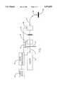
- FIG. 1is a schematic diagram of a laser system for distributing an output beam on a body according to the present invention.
- FIG. 2is a schematic diagram of a treatment head utilizing the laser system of FIG. 1.
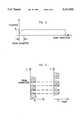
- FIG. 3is a schematic diagram of the template and a plurality of treatment patterns used in conjunction with the system of FIG. 1.
- FIG. 5is a graph showing the temperature profile orthogonal to the scan direction for the treatment patterns in FIG. 3.
- FIG. 6illustrates an alternative treatment pattern
- FIG. 7illustrates another alternative treatment pattern.
- the laser systemincludes a laser 10 which generates an output beam along path 11.
- the output beamis supplied through external beam path components 12 such as a shutter 13 and an attenuator 14.
- external beam path components 12such as a shutter 13 and an attenuator 14.
- the beamis delivered through a lens 15 into a fiber-optic coupler 16.
- the beamis then delivered through an optical fiber 17 to a treatment head 18, which distributes the laser beam output on a body 19.
- a data processor 20is coupled with the laser 10, the external beam path components 12, and the treatment head 18 for controlling operation of the system.
- User interface 21is coupled to the data processor 20, for providing user input utilized in controlling the system during treatment.
- Intense light sources other than laserssuch as arc lamps, LEDs, etc., can be used as well according to the present invention.
- FIG. 2provides a schematic illustration of a treatment head 18 which can be used in the present invention.
- This treatment headis similar to that described and disclosed in the above-referenced International Publication No. WO 87/06478.
- the fiber 17enters the treatment head 18 and is supplied to an aiming bracket 30.
- the aiming bracket 30establishes a propagation axis along which the laser output 31 from the fiber 17 proceeds.
- This aiming bracket 30is mounted on a mechanism, such as a plurality of stepper motors (of which motor 32 is representative), which are operative to scan the propagation axis defined by the bracket 30 through a scan plane transverse to the propagation axis. In the preferred system, this plane will be orthogonal to the propagation axis by the bracket 30.
- the output 31 from the fiber 17is supplied through a lens 33 past shutter 34, beam splitter 35, and through a template 36 to the treatment area.
- a photo detector 37is coupled with the beam splitter 35 for indicating the intensity of the output light.
- the lens 33can be an adjustable lens by which the spot size of the laser beam at the template 36 can be adjusted.
- FIG. 3illustrates one embodiment of the template 36 according to the present invention, and a plurality of treatment patterns numbered sequentially 1 through 12.
- the template 36has a rectangular opening 45 which allows passage of a laser beam into a treatment area.
- the treatment areahas been for this example divided into twelve lines, where each line is a treatment pattern to be scanned by the laser beam.
- the laser beamis positioned at point 46 on the template body 36 to begin a treatment.
- a first treatment patternis exposed by scanning the laser beam at essentially constant velocity along line 47 across the opening in the template 36 until the laser beam falls outside the opening.
- the laser beamis positioned for a second treatment pattern at point 48. From point 48 the beam is scanned at an essentially constant velocity across the opening until the propagation axis directs the beam outside the opening 45.
- These line-shaped treatment patternsare successively scanned in the order illustrated, where each sequential treatment pattern is non-adjacent to the next treatment pattern in the sequence.
- treatment patterns 1, 2, 3, 4, 5, and 6are spaced apart from one another.
- Treatment pattern 7is between patterns 1 and 2.
- Treatment pattern 8is between patterns 2 and 3.
- Treatment pattern 9is between patterns 3 and 4.
- Treatment pattern 10is between pattern 4 and 5.
- Treatment pattern 11is between patterns 5 and 6.
- treatment pattern 12is between the pattern 6 and the edge of the template 36.
- the fluence level throughout the entire treatment areacan be precisely controlled, and a uniform distribution of laser energy can be produced.
- the laser beamcan be left on while it is irradiating the template area during repositioning, or it can be turned off using the shutter 34, or the shutter 13 in the external beam path 12. Also, the beam can be turned off using a Q-switch within the laser system itself 10, or other apparatus known in the art. Further, the effect of the template can be achieved by proper timing of the shutter.
- FIG. 4is a graph of the temperature (trace 100) and fluence (trace 101) level versus scan direction for a particular treatment pattern, e.g. pattern 1, which correlates with the coordinate axes illustrated in FIG. 3.
- the fluence for a beam which is scanned at an essentially constant velocity with constant intensity across the treatment patternbegins centered at approximately -1 beam diameters at the beginning of the treatment pattern, rises to a constant level F T approximately one half beam diameter before getting into the treatment pattern, and continues at the constant value F T until approximately one half beam diameter after the end of the treatment pattern. This insures a constant fluence level.
- the transmitted fluence leveldrops to 0.
- the treatment temperature T T induced by this constant fluence levelrises rapidly after the edge 102 of the template to the preferred level and remains constant to the opposite edge 103 of the template.
- a scan of an essentially constant velocityallows for very even distribution of fluence through a treatment pattern. So long as all of the changes in velocity of the scan, such as occur at turns or when the scan is stopped, occur outside the treatment area on the template or after the shutter is closed, the fluence level in a treatment pattern can be very precisely, and evenly distributed.
- the treatment patterns used to fill the treatment areaare scanned in a manner so that each successive treatment pattern is not adjacent to a next treatment pattern.
- the thermal effect of this spacing of treatment patternsis illustrated in FIG. 5, where a cross-section of the temperature caused by successive scans is illustrated heuristically.
- the graph of FIG. 5includes a first temperature axis which shows the temperature profiles of the scans 1, 2, 3 and so on, and a second temperature axis which shows the temperature profiles of the scans 7, 8, and 9.
- treatment pattern number 7 on the second pass through the treatment areafills the area which was left untreated between treatment pattern numbers 1 and 2. A similar effect occurs with patterns 8 and 9 and so on.
- treatment patterns illustrated in FIG. 3are essentially straight lines having a finite width, they can be easily fitted together in a way which avoids leaving areas underexposed or overexposed.
- the treatment pattern illustrated with respect to FIG. 3provides that the scan direction for each treatment pattern will alternate, such that treatment pattern number 1 is scanned from left to right, while treatment pattern number 2 is scanned from right to left and so on. If the effects of the reduced temperatures at the beginning of a treatment pattern are critical, the treatment patterns can all be scanned in the same direction, so that the boundary of the uniform fluence level is more continuous.
- the template 36 illustrated with respect to FIGS. 3 and 4is rectangular in shape. However, these templates can be designed in a variety of shapes to meet the needs of a particular laser treatment. Furthermore, the intensity of the laser beam, the rate of scanning and the positioning of the various treatment patterns within the template can be precisely controlled with the data processing system.
- one method of the present invention for distributing a constant fluence level of laser radiation in a treatmentincludes:
- the treatment patterncan either completely fill the template, or the step of scanning can be successively repeated so that the laser beam scans a plurality of essentially continuously scanned treatment patterns to fill the treatment region.
- the distribution of temperature caused by the laser scanningcan be controlled further by positioning successively scanned treatment patterns so that a first sequential treatment pattern is positioned non-adjacent to a next sequential treatment pattern.
- the step of scanningcan be computer controlled so that it includes turning on the laser beam while the propagation axis directs the laser beam outside of the opening of the template, scanning the propagation axis at a constant velocity across the opening while the laser beam is on until the laser beam is directed outside of the opening, and while the laser beam is directed outside of the opening, repositioning the propagation axis of the laser beam for a successive treatment pattern.
- Another method of the present invention for distributing a constant fluence levelinclude:
- the treatment patternwill have a width of at least one beam diameter, and a length of more than one, and preferably many, beam diameters. Further, the treatment patterns used to fill a treatment region can take a variety of shapes as suits the needs of a particular situation.
- the need for a templateis minimized, and the shape of the outside dimensions of the treatment region can be precisely controlled using a computer. It is desirable to have the propagation axis being scanned when the laser beam is enabled so that the beam does not overexpose or underexpose the starting point of the scan.
- FIGS. 6 and 7illustrate alternative treatment patterns which can be utilized according to the present invention.
- the treatment patternis essentially a spiral.
- shutter control or Q-switch control of the laser lightthe spiral provides for placing sequential scans 1-5 of the beam non-adjacent previous scans.
- the spiralcan be effectively used to provide a constant fluence level within a treatment area.
- FIG. 7illustrates a treatment pattern consisting of concentric rings having respective radii and radial width.
- the concentric ringscould be scanned such that rings 1, 3 and 5 are scanned in a first pass, and rings 2 and 4 are scanned in a second pass to insure that sequential treatment patterns are non-adjacent.
- This computer controlled scanning technique for treatment of dermatology-related disorders with a consistent fluence level throughout the treatment areaprovides significant advantages over the prior art. It allows for the shape of the treatment area to be precisely controlled, while insuring a constant fluence level which entirely fills the treatment area. With computer control, the intensity and scan velocity can be precisely controlled so that the fluence level actually distributed throughout the treatment area can be selected over a wide range with high accuracy and uniformly distributed.
- the preferred laser 10 for dermatological applicationssuch as the treatment of planar angiomas is a Nd:YAG laser providing a frequency-doubled output of 532 nanometers or 659 nanometers, such as is commercially available from Laserscope Corp. in San Jose, Calif.
- other laser systemssuch as argon ion lasers, dye lasers, or copper vapor lasers commonly used in dermatology applications can be utilized.
Landscapes
- Physics & Mathematics (AREA)
- Health & Medical Sciences (AREA)
- Surgery (AREA)
- Optics & Photonics (AREA)
- Life Sciences & Earth Sciences (AREA)
- Engineering & Computer Science (AREA)
- Otolaryngology (AREA)
- Nuclear Medicine, Radiotherapy & Molecular Imaging (AREA)
- Electromagnetism (AREA)
- Biomedical Technology (AREA)
- Heart & Thoracic Surgery (AREA)
- Medical Informatics (AREA)
- Molecular Biology (AREA)
- Animal Behavior & Ethology (AREA)
- General Health & Medical Sciences (AREA)
- Public Health (AREA)
- Veterinary Medicine (AREA)
- Radiation-Therapy Devices (AREA)
Abstract
Description
Claims (33)
Priority Applications (1)
| Application Number | Priority Date | Filing Date | Title |
|---|---|---|---|
| US08/020,255US5474549A (en) | 1991-07-09 | 1993-02-18 | Method and system for scanning a laser beam for controlled distribution of laser dosage |
Applications Claiming Priority (2)
| Application Number | Priority Date | Filing Date | Title |
|---|---|---|---|
| US72755991A | 1991-07-09 | 1991-07-09 | |
| US08/020,255US5474549A (en) | 1991-07-09 | 1993-02-18 | Method and system for scanning a laser beam for controlled distribution of laser dosage |
Related Parent Applications (1)
| Application Number | Title | Priority Date | Filing Date |
|---|---|---|---|
| US72755991AContinuation | 1991-07-09 | 1991-07-09 |
Publications (1)
| Publication Number | Publication Date |
|---|---|
| US5474549Atrue US5474549A (en) | 1995-12-12 |
Family
ID=24923132
Family Applications (1)
| Application Number | Title | Priority Date | Filing Date |
|---|---|---|---|
| US08/020,255Expired - LifetimeUS5474549A (en) | 1991-07-09 | 1993-02-18 | Method and system for scanning a laser beam for controlled distribution of laser dosage |
Country Status (1)
| Country | Link |
|---|---|
| US (1) | US5474549A (en) |
Cited By (89)
| Publication number | Priority date | Publication date | Assignee | Title |
|---|---|---|---|---|
| US5595568A (en)* | 1995-02-01 | 1997-01-21 | The General Hospital Corporation | Permanent hair removal using optical pulses |
| US5630811A (en)* | 1996-03-25 | 1997-05-20 | Miller; Iain D. | Method and apparatus for hair removal |
| US5653706A (en)* | 1993-07-21 | 1997-08-05 | Lucid Technologies Inc. | Dermatological laser treatment system with electronic visualization of the area being treated |
| US5658323A (en)* | 1995-07-12 | 1997-08-19 | Miller; Iain D. | Method and apparatus for dermatology treatment |
| WO1998025528A1 (en)* | 1996-12-10 | 1998-06-18 | Asah Medico A/S | An apparatus for cosmetic tissue treatment |
| US5798498A (en)* | 1993-12-17 | 1998-08-25 | Laser Industries, Ltd. | Method and apparatus for applying laser beams to a working surface, particularly for ablating tissue |
| US5807386A (en)* | 1995-02-03 | 1998-09-15 | Laser Industries, Ltd. | Laser facial rejuvenation |
| US5827266A (en)* | 1995-10-01 | 1998-10-27 | Optomedic Medical Technologies, Ltd. | Scanner |
| US5879376A (en)* | 1995-07-12 | 1999-03-09 | Luxar Corporation | Method and apparatus for dermatology treatment |
| WO1999017668A1 (en)* | 1997-10-08 | 1999-04-15 | The General Hospital Corporation | Phototherapy methods and systems |
| US5906609A (en)* | 1997-02-05 | 1999-05-25 | Sahar Technologies | Method for delivering energy within continuous outline |
| US5938657A (en)* | 1997-02-05 | 1999-08-17 | Sahar Technologies, Inc. | Apparatus for delivering energy within continuous outline |
| US5968033A (en)* | 1997-11-03 | 1999-10-19 | Fuller Research Corporation | Optical delivery system and method for subsurface tissue irradiation |
| US6074382A (en)* | 1997-08-29 | 2000-06-13 | Asah Medico A/S | Apparatus for tissue treatment |
| US6117129A (en)* | 1997-05-30 | 2000-09-12 | Nidek Co., Ltd. | Laser treatment apparatus |
| WO2000054686A1 (en)* | 1999-03-15 | 2000-09-21 | Altus Medical, Inc. | Radiation delivery module and dermal tissue treatment method |
| US6165205A (en)* | 1998-07-10 | 2000-12-26 | Ceramoptec Industries, Inc. | Method for improved wound healing |
| US6190376B1 (en) | 1996-12-10 | 2001-02-20 | Asah Medico A/S | Apparatus for tissue treatment |
| EP1090600A2 (en) | 1999-04-23 | 2001-04-11 | Biolase Technology, Inc. | Electromagnetically induced cutting with atomized fluid particles for dermatological applications |
| US6228074B1 (en) | 1998-10-15 | 2001-05-08 | Stephen Almeida | Multiple pulse photo-epilator |
| US6235015B1 (en)* | 1997-05-14 | 2001-05-22 | Applied Optronics Corporation | Method and apparatus for selective hair depilation using a scanned beam of light at 600 to 1000 nm |
| US20010016732A1 (en)* | 1998-02-03 | 2001-08-23 | James L. Hobart | Dual mode laser delivery system providing controllable depth of tissue ablation and corresponding controllable depth of coagulation |
| US6383176B1 (en) | 1999-03-15 | 2002-05-07 | Altus Medical, Inc. | Hair removal device and method |
| EP1118311A3 (en)* | 2000-01-06 | 2002-07-17 | S.L.T. Japan Co., Ltd. | Apparatus for laser light irradiation to living body |
| US6450180B1 (en)* | 1996-11-21 | 2002-09-17 | Oramir Semiconductor Equipment Ltd. | Method and apparatus for the laser processing of substrate surfaces |
| US6508813B1 (en) | 1996-12-02 | 2003-01-21 | Palomar Medical Technologies, Inc. | System for electromagnetic radiation dermatology and head for use therewith |
| US6511475B1 (en) | 1997-05-15 | 2003-01-28 | The General Hospital Corporation | Heads for dermatology treatment |
| US6517532B1 (en) | 1997-05-15 | 2003-02-11 | Palomar Medical Technologies, Inc. | Light energy delivery head |
| US20030036680A1 (en)* | 2001-08-15 | 2003-02-20 | Michael Black | Method and apparatus for thermal ablation of biological tissue using a scanning laser beam with real-time video monitoring and monitoring of therapeutic treatment parameters |
| US6575964B1 (en) | 1998-02-03 | 2003-06-10 | Sciton, Inc. | Selective aperture for laser delivery system for providing incision, tissue ablation and coagulation |
| US6575963B1 (en) | 1997-07-16 | 2003-06-10 | The Lion Eye Institute Of Western Australia Incorporated | Laser scanning apparatus and method |
| US6595986B2 (en) | 1998-10-15 | 2003-07-22 | Stephen Almeida | Multiple pulse photo-dermatological device |
| US6605080B1 (en) | 1998-03-27 | 2003-08-12 | The General Hospital Corporation | Method and apparatus for the selective targeting of lipid-rich tissues |
| US6607523B1 (en) | 1999-03-19 | 2003-08-19 | Asah Medico A/S | Apparatus for tissue treatment |
| EP1354573A1 (en)* | 2002-04-08 | 2003-10-22 | Lumenis Inc. | System, method and apparatus for providing uniform illumination |
| US6653618B2 (en) | 2000-04-28 | 2003-11-25 | Palomar Medical Technologies, Inc. | Contact detecting method and apparatus for an optical radiation handpiece |
| US6660000B2 (en) | 1999-09-30 | 2003-12-09 | Ceramoptec Industries, Inc. | Device for application of radiation |
| US6676654B1 (en) | 1997-08-29 | 2004-01-13 | Asah Medico A/S | Apparatus for tissue treatment and having a monitor for display of tissue features |
| US6723090B2 (en) | 2001-07-02 | 2004-04-20 | Palomar Medical Technologies, Inc. | Fiber laser device for medical/cosmetic procedures |
| US6743221B1 (en) | 2001-03-13 | 2004-06-01 | James L. Hobart | Laser system and method for treatment of biological tissues |
| US20040116984A1 (en)* | 2002-12-12 | 2004-06-17 | Greg Spooner | Method and system for controlled spatially-selective epidermal pigmentation phototherapy with UVA LEDs |
| US20040143247A1 (en)* | 1997-02-05 | 2004-07-22 | Anderson R. Rox | Method and apparatus for treating wrinkles in skin using radiation |
| US6770069B1 (en) | 2001-06-22 | 2004-08-03 | Sciton, Inc. | Laser applicator |
| US20050141068A1 (en)* | 2003-12-31 | 2005-06-30 | Debenedictis Leonard C. | High speed, high efficiency optical pattern generator using rotating optical elements |
| US20050259306A1 (en)* | 2003-12-31 | 2005-11-24 | Broome Barry G | Two-dimensional optical scan system using a counter-rotating disk scanner |
| US20050285928A1 (en)* | 2003-12-31 | 2005-12-29 | Broome Barry G | Optical pattern generator using a single rotating component |
| US6997923B2 (en) | 2000-12-28 | 2006-02-14 | Palomar Medical Technologies, Inc. | Method and apparatus for EMR treatment |
| US7029469B2 (en) | 1998-12-03 | 2006-04-18 | Palomar Medical Technologies, Inc. | Method and apparatus for laser removal of hair |
| US20060084954A1 (en)* | 2004-08-17 | 2006-04-20 | Intralase Corp. | Apparatus and method for correction of abberations in laser system optics |
| US7041094B2 (en) | 1999-03-15 | 2006-05-09 | Cutera, Inc. | Tissue treatment device and method |
| US7044959B2 (en) | 2002-03-12 | 2006-05-16 | Palomar Medical Technologies, Inc. | Method and apparatus for hair growth management |
| US7090670B2 (en) | 2003-12-31 | 2006-08-15 | Reliant Technologies, Inc. | Multi-spot laser surgical apparatus and method |
| US7135033B2 (en) | 2002-05-23 | 2006-11-14 | Palomar Medical Technologies, Inc. | Phototreatment device for use with coolants and topical substances |
| US7204832B2 (en) | 1996-12-02 | 2007-04-17 | Pálomar Medical Technologies, Inc. | Cooling system for a photo cosmetic device |
| US7220254B2 (en) | 2003-12-31 | 2007-05-22 | Palomar Medical Technologies, Inc. | Dermatological treatment with visualization |
| US7274155B2 (en) | 2001-03-01 | 2007-09-25 | Palomar Medical Technologies, Inc. | Flash lamp drive circuit |
| US7276058B2 (en) | 2002-06-19 | 2007-10-02 | Palomar Medical Technologies, Inc. | Method and apparatus for treatment of cutaneous and subcutaneous conditions |
| US7282060B2 (en) | 2003-12-23 | 2007-10-16 | Reliant Technologies, Inc. | Method and apparatus for monitoring and controlling laser-induced tissue treatment |
| US7291140B2 (en) | 2003-07-18 | 2007-11-06 | Cutera, Inc. | System and method for low average power dermatologic light treatment device |
| US20070265606A1 (en)* | 2003-02-14 | 2007-11-15 | Reliant Technologies, Inc. | Method and Apparatus for Fractional Light-based Treatment of Obstructive Sleep Apnea |
| US20080009923A1 (en)* | 2006-06-14 | 2008-01-10 | Paithankar Dilip Y | Treatment of Skin by Spatial Modulation of Thermal Heating |
| US7326199B2 (en) | 2003-12-22 | 2008-02-05 | Cutera, Inc. | System and method for flexible architecture for dermatologic treatments utilizing multiple light sources |
| US20080058783A1 (en)* | 2003-11-04 | 2008-03-06 | Palomar Medical Technologies, Inc. | Handheld Photocosmetic Device |
| US7351252B2 (en) | 2002-06-19 | 2008-04-01 | Palomar Medical Technologies, Inc. | Method and apparatus for photothermal treatment of tissue at depth |
| US7413572B2 (en) | 2004-06-14 | 2008-08-19 | Reliant Technologies, Inc. | Adaptive control of optical pulses for laser medicine |
| WO2008057154A3 (en)* | 2006-09-06 | 2008-08-21 | Shaser Inc | Scanning laser system for the treatment of tissue |
| US7438713B2 (en) | 2001-03-22 | 2008-10-21 | Lumenis, Inc. | Scanning laser handpiece with shaped output beam |
| US20090030408A1 (en)* | 2007-07-28 | 2009-01-29 | Fotona D.D. | Laser System for Medical Removal of Body Tissue |
| US7540869B2 (en) | 2001-12-27 | 2009-06-02 | Palomar Medical Technologies, Inc. | Method and apparatus for improved vascular related treatment |
| US7722600B2 (en) | 2003-08-25 | 2010-05-25 | Cutera, Inc. | System and method for heating skin using light to provide tissue treatment |
| US7837675B2 (en) | 2004-07-22 | 2010-11-23 | Shaser, Inc. | Method and device for skin treatment with replaceable photosensitive window |
| US7891362B2 (en) | 2005-12-23 | 2011-02-22 | Candela Corporation | Methods for treating pigmentary and vascular abnormalities in a dermal region |
| USRE42594E1 (en) | 1998-10-16 | 2011-08-02 | Reliant Technologies, Inc. | Tissue cooling rod for laser surgery |
| US8182473B2 (en) | 1999-01-08 | 2012-05-22 | Palomar Medical Technologies | Cooling system for a photocosmetic device |
| US8268332B2 (en) | 2004-04-01 | 2012-09-18 | The General Hospital Corporation | Method for dermatological treatment using chromophores |
| US8277495B2 (en) | 2005-01-13 | 2012-10-02 | Candela Corporation | Method and apparatus for treating a diseased nail |
| US8346347B2 (en) | 2005-09-15 | 2013-01-01 | Palomar Medical Technologies, Inc. | Skin optical characterization device |
| US8870856B2 (en) | 2003-08-25 | 2014-10-28 | Cutera, Inc. | Method for heating skin using light to provide tissue treatment |
| US8915906B2 (en) | 2003-08-25 | 2014-12-23 | Cutera, Inc. | Method for treatment of post-partum abdominal skin redundancy or laxity |
| US9028469B2 (en) | 2005-09-28 | 2015-05-12 | Candela Corporation | Method of treating cellulite |
| US9028536B2 (en) | 2006-08-02 | 2015-05-12 | Cynosure, Inc. | Picosecond laser apparatus and methods for its operation and use |
| US9351792B2 (en) | 2003-03-27 | 2016-05-31 | The General Hospital Corporation | Method and apparatus for dermatological treatment and fractional skin resurfacing |
| US9780518B2 (en) | 2012-04-18 | 2017-10-03 | Cynosure, Inc. | Picosecond laser apparatus and methods for treating target tissues with same |
| US9919168B2 (en) | 2009-07-23 | 2018-03-20 | Palomar Medical Technologies, Inc. | Method for improvement of cellulite appearance |
| CN108338835A (en)* | 2018-04-27 | 2018-07-31 | 刘喜 | A kind for the treatment of region can random variation carbon dioxide dot matrix laser therapeutic apparantus |
| US10245107B2 (en) | 2013-03-15 | 2019-04-02 | Cynosure, Inc. | Picosecond optical radiation systems and methods of use |
| JP2019513500A (en)* | 2016-04-19 | 2019-05-30 | オ アンド リー メディカル ロボット インコーポレイテッドOh & Lee Medical Robot,Inc. | Control method of movement pattern for laser treatment and laser irradiation apparatus using the same |
| US10434324B2 (en) | 2005-04-22 | 2019-10-08 | Cynosure, Llc | Methods and systems for laser treatment using non-uniform output beam |
| US11418000B2 (en) | 2018-02-26 | 2022-08-16 | Cynosure, Llc | Q-switched cavity dumped sub-nanosecond laser |
Citations (6)
| Publication number | Priority date | Publication date | Assignee | Title |
|---|---|---|---|---|
| US4215694A (en)* | 1978-06-01 | 1980-08-05 | Isakov Viktor L | Laser therapy apparatus |
| US4665913A (en)* | 1983-11-17 | 1987-05-19 | Lri L.P. | Method for ophthalmological surgery |
| WO1987006478A1 (en)* | 1986-04-30 | 1987-11-05 | Institut National De La Sante Et De La Recherche M | Systematized treatment instrument, using particularly laser energy, useful for example in dermatology |
| US4718416A (en)* | 1984-01-13 | 1988-01-12 | Kabushiki Kaisha Toshiba | Laser treatment apparatus |
| US5035693A (en)* | 1987-03-16 | 1991-07-30 | Michael Kratzer | Device for selective destruction of cells |
| US5053006A (en)* | 1988-04-19 | 1991-10-01 | Watson Brant D | Method for the permanent occlusion of arteries |
- 1993
- 1993-02-18USUS08/020,255patent/US5474549A/ennot_activeExpired - Lifetime
Patent Citations (6)
| Publication number | Priority date | Publication date | Assignee | Title |
|---|---|---|---|---|
| US4215694A (en)* | 1978-06-01 | 1980-08-05 | Isakov Viktor L | Laser therapy apparatus |
| US4665913A (en)* | 1983-11-17 | 1987-05-19 | Lri L.P. | Method for ophthalmological surgery |
| US4718416A (en)* | 1984-01-13 | 1988-01-12 | Kabushiki Kaisha Toshiba | Laser treatment apparatus |
| WO1987006478A1 (en)* | 1986-04-30 | 1987-11-05 | Institut National De La Sante Et De La Recherche M | Systematized treatment instrument, using particularly laser energy, useful for example in dermatology |
| US5035693A (en)* | 1987-03-16 | 1991-07-30 | Michael Kratzer | Device for selective destruction of cells |
| US5053006A (en)* | 1988-04-19 | 1991-10-01 | Watson Brant D | Method for the permanent occlusion of arteries |
Cited By (173)
| Publication number | Priority date | Publication date | Assignee | Title |
|---|---|---|---|---|
| US5653706A (en)* | 1993-07-21 | 1997-08-05 | Lucid Technologies Inc. | Dermatological laser treatment system with electronic visualization of the area being treated |
| US5798498A (en)* | 1993-12-17 | 1998-08-25 | Laser Industries, Ltd. | Method and apparatus for applying laser beams to a working surface, particularly for ablating tissue |
| US5814042A (en)* | 1993-12-17 | 1998-09-29 | Laser Industries, Ltd. | Apparatus for applying laser beam to living tissue to cause uniform ablation of living tissue while not causing thermal damage below a predetermined depth to the surrounding tissue |
| US5595568A (en)* | 1995-02-01 | 1997-01-21 | The General Hospital Corporation | Permanent hair removal using optical pulses |
| US5807386A (en)* | 1995-02-03 | 1998-09-15 | Laser Industries, Ltd. | Laser facial rejuvenation |
| US6027495A (en)* | 1995-07-12 | 2000-02-22 | Esc Medical Systems Ltd. | Method and apparatus for dermatology treatment |
| US5658323A (en)* | 1995-07-12 | 1997-08-19 | Miller; Iain D. | Method and apparatus for dermatology treatment |
| US5879376A (en)* | 1995-07-12 | 1999-03-09 | Luxar Corporation | Method and apparatus for dermatology treatment |
| US5827266A (en)* | 1995-10-01 | 1998-10-27 | Optomedic Medical Technologies, Ltd. | Scanner |
| US5630811A (en)* | 1996-03-25 | 1997-05-20 | Miller; Iain D. | Method and apparatus for hair removal |
| US5853407A (en)* | 1996-03-25 | 1998-12-29 | Luxar Corporation | Method and apparatus for hair removal |
| US6450180B1 (en)* | 1996-11-21 | 2002-09-17 | Oramir Semiconductor Equipment Ltd. | Method and apparatus for the laser processing of substrate surfaces |
| US7431719B2 (en) | 1996-12-02 | 2008-10-07 | Palomar Medical Technologies, Inc. | System for electromagnetic radiation dermatology and head for use therewith |
| US6878144B2 (en) | 1996-12-02 | 2005-04-12 | Palomar Medical Technologies, Inc. | System for electromagnetic radiation dermatology and head for use therewith |
| US8328794B2 (en) | 1996-12-02 | 2012-12-11 | Palomar Medical Technologies, Inc. | System for electromagnetic radiation dermatology and head for use therewith |
| US7204832B2 (en) | 1996-12-02 | 2007-04-17 | Pálomar Medical Technologies, Inc. | Cooling system for a photo cosmetic device |
| US6508813B1 (en) | 1996-12-02 | 2003-01-21 | Palomar Medical Technologies, Inc. | System for electromagnetic radiation dermatology and head for use therewith |
| US6190376B1 (en) | 1996-12-10 | 2001-02-20 | Asah Medico A/S | Apparatus for tissue treatment |
| WO1998025528A1 (en)* | 1996-12-10 | 1998-06-18 | Asah Medico A/S | An apparatus for cosmetic tissue treatment |
| US6533776B2 (en) | 1996-12-10 | 2003-03-18 | Asah Medico A/S | Apparatus for tissue treatment |
| US5938657A (en)* | 1997-02-05 | 1999-08-17 | Sahar Technologies, Inc. | Apparatus for delivering energy within continuous outline |
| US5906609A (en)* | 1997-02-05 | 1999-05-25 | Sahar Technologies | Method for delivering energy within continuous outline |
| US20040143247A1 (en)* | 1997-02-05 | 2004-07-22 | Anderson R. Rox | Method and apparatus for treating wrinkles in skin using radiation |
| US20050256515A1 (en)* | 1997-02-05 | 2005-11-17 | Anderson R R | Method and apparatus for treating wrinkles in skin using radiation |
| US6235015B1 (en)* | 1997-05-14 | 2001-05-22 | Applied Optronics Corporation | Method and apparatus for selective hair depilation using a scanned beam of light at 600 to 1000 nm |
| US8328796B2 (en) | 1997-05-15 | 2012-12-11 | Palomar Medical Technologies, Inc. | Light energy delivery head |
| US6511475B1 (en) | 1997-05-15 | 2003-01-28 | The General Hospital Corporation | Heads for dermatology treatment |
| US7935107B2 (en) | 1997-05-15 | 2011-05-03 | Palomar Medical Technologies, Inc. | Heads for dermatology treatment |
| US6974451B2 (en) | 1997-05-15 | 2005-12-13 | Palomar Medical Technologies, Inc. | Light energy delivery head |
| US7763016B2 (en) | 1997-05-15 | 2010-07-27 | Palomar Medical Technologies, Inc. | Light energy delivery head |
| US6663620B2 (en) | 1997-05-15 | 2003-12-16 | Palomar Medical Technologies, Inc. | Light energy delivery head |
| US20030195494A1 (en)* | 1997-05-15 | 2003-10-16 | Altshuler Gregory B. | Light energy delivery head |
| US6976985B2 (en) | 1997-05-15 | 2005-12-20 | Palomar Medical Technologies, Inc. | Light energy delivery head |
| US6517532B1 (en) | 1997-05-15 | 2003-02-11 | Palomar Medical Technologies, Inc. | Light energy delivery head |
| US8002768B1 (en) | 1997-05-15 | 2011-08-23 | Palomar Medical Technologies, Inc. | Light energy delivery head |
| US7758621B2 (en) | 1997-05-15 | 2010-07-20 | Palomar Medical Technologies, Inc. | Method and apparatus for therapeutic EMR treatment on the skin |
| US8109924B2 (en) | 1997-05-15 | 2012-02-07 | Palomar Medical Technologies, Inc. | Heads for dermatology treatment |
| US7077840B2 (en) | 1997-05-15 | 2006-07-18 | Palomar Medical Technologies, Inc. | Heads for dermatology treatment |
| US6117129A (en)* | 1997-05-30 | 2000-09-12 | Nidek Co., Ltd. | Laser treatment apparatus |
| US6575963B1 (en) | 1997-07-16 | 2003-06-10 | The Lion Eye Institute Of Western Australia Incorporated | Laser scanning apparatus and method |
| US6676654B1 (en) | 1997-08-29 | 2004-01-13 | Asah Medico A/S | Apparatus for tissue treatment and having a monitor for display of tissue features |
| US6383177B1 (en) | 1997-08-29 | 2002-05-07 | Asah Medico A/S | Apparatus for tissue treatment |
| US6074382A (en)* | 1997-08-29 | 2000-06-13 | Asah Medico A/S | Apparatus for tissue treatment |
| USRE38670E1 (en)* | 1997-08-29 | 2004-12-14 | Asah Medico A/S | Apparatus for tissue treatment |
| US20060085053A1 (en)* | 1997-10-08 | 2006-04-20 | Anderson Richard R | Phototherapy methods and systems |
| US6436127B1 (en) | 1997-10-08 | 2002-08-20 | The General Hospital Corporation | Phototherapy methods and systems |
| WO1999017668A1 (en)* | 1997-10-08 | 1999-04-15 | The General Hospital Corporation | Phototherapy methods and systems |
| US6984228B2 (en) | 1997-10-08 | 2006-01-10 | The General Hospital Corporation | Phototherapy methods and systems |
| US5968033A (en)* | 1997-11-03 | 1999-10-19 | Fuller Research Corporation | Optical delivery system and method for subsurface tissue irradiation |
| US20010016732A1 (en)* | 1998-02-03 | 2001-08-23 | James L. Hobart | Dual mode laser delivery system providing controllable depth of tissue ablation and corresponding controllable depth of coagulation |
| US6575964B1 (en) | 1998-02-03 | 2003-06-10 | Sciton, Inc. | Selective aperture for laser delivery system for providing incision, tissue ablation and coagulation |
| US6605080B1 (en) | 1998-03-27 | 2003-08-12 | The General Hospital Corporation | Method and apparatus for the selective targeting of lipid-rich tissues |
| US7060061B2 (en) | 1998-03-27 | 2006-06-13 | Palomar Medical Technologies, Inc. | Method and apparatus for the selective targeting of lipid-rich tissues |
| US6165205A (en)* | 1998-07-10 | 2000-12-26 | Ceramoptec Industries, Inc. | Method for improved wound healing |
| US6228074B1 (en) | 1998-10-15 | 2001-05-08 | Stephen Almeida | Multiple pulse photo-epilator |
| US7097639B1 (en) | 1998-10-15 | 2006-08-29 | Zian Medical, Llc | Dual filter multiple pulse photo-dermatological device with pre/post optical heating, quasi-logarithmic spacing, and laser rod spectrum infusion |
| US6595986B2 (en) | 1998-10-15 | 2003-07-22 | Stephen Almeida | Multiple pulse photo-dermatological device |
| USRE42594E1 (en) | 1998-10-16 | 2011-08-02 | Reliant Technologies, Inc. | Tissue cooling rod for laser surgery |
| USRE43881E1 (en) | 1998-10-16 | 2012-12-25 | Reliant Technologies, Inc. | Tissue cooling rod for laser surgery |
| USRE46208E1 (en) | 1998-10-16 | 2016-11-22 | Reliant Technologies, Llc | Method for cryogenically treating tissue below the skin surface |
| US7029469B2 (en) | 1998-12-03 | 2006-04-18 | Palomar Medical Technologies, Inc. | Method and apparatus for laser removal of hair |
| US8182473B2 (en) | 1999-01-08 | 2012-05-22 | Palomar Medical Technologies | Cooling system for a photocosmetic device |
| US6383176B1 (en) | 1999-03-15 | 2002-05-07 | Altus Medical, Inc. | Hair removal device and method |
| WO2000054686A1 (en)* | 1999-03-15 | 2000-09-21 | Altus Medical, Inc. | Radiation delivery module and dermal tissue treatment method |
| US7524328B2 (en) | 1999-03-15 | 2009-04-28 | Cutera, Inc. | Radiation delivery module and dermal tissue treatment method |
| US6569155B1 (en) | 1999-03-15 | 2003-05-27 | Altus Medical, Inc. | Radiation delivery module and dermal tissue treatment method |
| US6485484B1 (en) | 1999-03-15 | 2002-11-26 | Altus Medical, Inc. | Hair removal device |
| US20040015157A1 (en)* | 1999-03-15 | 2004-01-22 | Altus Medical, Inc. A Corporation Of Delaware | Radiation delivery module and dermal tissue treatment method |
| US7041094B2 (en) | 1999-03-15 | 2006-05-09 | Cutera, Inc. | Tissue treatment device and method |
| US7618414B2 (en) | 1999-03-15 | 2009-11-17 | Cutera, Inc. | Tissue treatment system |
| US7465307B2 (en) | 1999-03-15 | 2008-12-16 | Cutera, Inc. | Tissue treatment system |
| US6607523B1 (en) | 1999-03-19 | 2003-08-19 | Asah Medico A/S | Apparatus for tissue treatment |
| EP1090600A2 (en) | 1999-04-23 | 2001-04-11 | Biolase Technology, Inc. | Electromagnetically induced cutting with atomized fluid particles for dermatological applications |
| WO2001023032A3 (en)* | 1999-09-30 | 2008-04-03 | Ceramoptec Ind Inc | Device and method for application of radiation |
| US6660000B2 (en) | 1999-09-30 | 2003-12-09 | Ceramoptec Industries, Inc. | Device for application of radiation |
| EP1118311A3 (en)* | 2000-01-06 | 2002-07-17 | S.L.T. Japan Co., Ltd. | Apparatus for laser light irradiation to living body |
| US6653618B2 (en) | 2000-04-28 | 2003-11-25 | Palomar Medical Technologies, Inc. | Contact detecting method and apparatus for an optical radiation handpiece |
| US6997923B2 (en) | 2000-12-28 | 2006-02-14 | Palomar Medical Technologies, Inc. | Method and apparatus for EMR treatment |
| US7274155B2 (en) | 2001-03-01 | 2007-09-25 | Palomar Medical Technologies, Inc. | Flash lamp drive circuit |
| US7531967B2 (en) | 2001-03-01 | 2009-05-12 | Palomar Medical Technologies, Inc. | Flashlamp drive circuit |
| US6743221B1 (en) | 2001-03-13 | 2004-06-01 | James L. Hobart | Laser system and method for treatment of biological tissues |
| US7220256B2 (en) | 2001-03-13 | 2007-05-22 | Hobart James L | Laser system and method for treatment of biological tissues |
| US7824396B2 (en) | 2001-03-22 | 2010-11-02 | Lumenis Ltd. | Scanner laser handpiece with shaped output beam |
| US7438713B2 (en) | 2001-03-22 | 2008-10-21 | Lumenis, Inc. | Scanning laser handpiece with shaped output beam |
| US20090105699A1 (en)* | 2001-03-22 | 2009-04-23 | Lumenis Ltd. | Scanner Laser Handpiece with Shaped Output Beam |
| US6770069B1 (en) | 2001-06-22 | 2004-08-03 | Sciton, Inc. | Laser applicator |
| US6723090B2 (en) | 2001-07-02 | 2004-04-20 | Palomar Medical Technologies, Inc. | Fiber laser device for medical/cosmetic procedures |
| US20030036680A1 (en)* | 2001-08-15 | 2003-02-20 | Michael Black | Method and apparatus for thermal ablation of biological tissue using a scanning laser beam with real-time video monitoring and monitoring of therapeutic treatment parameters |
| US7540869B2 (en) | 2001-12-27 | 2009-06-02 | Palomar Medical Technologies, Inc. | Method and apparatus for improved vascular related treatment |
| US7044959B2 (en) | 2002-03-12 | 2006-05-16 | Palomar Medical Technologies, Inc. | Method and apparatus for hair growth management |
| JP2004121814A (en)* | 2002-04-08 | 2004-04-22 | Lumenis Inc | System, method and apparatus for providing uniform illumination |
| EP1354573A1 (en)* | 2002-04-08 | 2003-10-22 | Lumenis Inc. | System, method and apparatus for providing uniform illumination |
| US20030231827A1 (en)* | 2002-04-08 | 2003-12-18 | Andersen Dan E. | System, method and apparatus for providing uniform illumination |
| US7263255B2 (en) | 2002-04-08 | 2007-08-28 | Lumenis Inc. | System, method and apparatus for providing uniform illumination |
| US7135033B2 (en) | 2002-05-23 | 2006-11-14 | Palomar Medical Technologies, Inc. | Phototreatment device for use with coolants and topical substances |
| US7942915B2 (en) | 2002-05-23 | 2011-05-17 | Palomar Medical Technologies, Inc. | Phototreatment device for use with coolants |
| US7942916B2 (en) | 2002-05-23 | 2011-05-17 | Palomar Medical Technologies, Inc. | Phototreatment device for use with coolants and topical substances |
| US7276058B2 (en) | 2002-06-19 | 2007-10-02 | Palomar Medical Technologies, Inc. | Method and apparatus for treatment of cutaneous and subcutaneous conditions |
| US7351252B2 (en) | 2002-06-19 | 2008-04-01 | Palomar Medical Technologies, Inc. | Method and apparatus for photothermal treatment of tissue at depth |
| US8915948B2 (en) | 2002-06-19 | 2014-12-23 | Palomar Medical Technologies, Llc | Method and apparatus for photothermal treatment of tissue at depth |
| US10500413B2 (en) | 2002-06-19 | 2019-12-10 | Palomar Medical Technologies, Llc | Method and apparatus for treatment of cutaneous and subcutaneous conditions |
| US10556123B2 (en) | 2002-06-19 | 2020-02-11 | Palomar Medical Technologies, Llc | Method and apparatus for treatment of cutaneous and subcutaneous conditions |
| US20060089687A1 (en)* | 2002-12-12 | 2006-04-27 | Greg Spooner | System for controlled spatially-selective epidermal pigmentation phototherapy with UVA LEDs |
| US20040116984A1 (en)* | 2002-12-12 | 2004-06-17 | Greg Spooner | Method and system for controlled spatially-selective epidermal pigmentation phototherapy with UVA LEDs |
| US6991644B2 (en) | 2002-12-12 | 2006-01-31 | Cutera, Inc. | Method and system for controlled spatially-selective epidermal pigmentation phototherapy with UVA LEDs |
| US20070265606A1 (en)* | 2003-02-14 | 2007-11-15 | Reliant Technologies, Inc. | Method and Apparatus for Fractional Light-based Treatment of Obstructive Sleep Apnea |
| US9351792B2 (en) | 2003-03-27 | 2016-05-31 | The General Hospital Corporation | Method and apparatus for dermatological treatment and fractional skin resurfacing |
| US7291140B2 (en) | 2003-07-18 | 2007-11-06 | Cutera, Inc. | System and method for low average power dermatologic light treatment device |
| US7722600B2 (en) | 2003-08-25 | 2010-05-25 | Cutera, Inc. | System and method for heating skin using light to provide tissue treatment |
| US8915906B2 (en) | 2003-08-25 | 2014-12-23 | Cutera, Inc. | Method for treatment of post-partum abdominal skin redundancy or laxity |
| US8870856B2 (en) | 2003-08-25 | 2014-10-28 | Cutera, Inc. | Method for heating skin using light to provide tissue treatment |
| US20080058783A1 (en)* | 2003-11-04 | 2008-03-06 | Palomar Medical Technologies, Inc. | Handheld Photocosmetic Device |
| US7326199B2 (en) | 2003-12-22 | 2008-02-05 | Cutera, Inc. | System and method for flexible architecture for dermatologic treatments utilizing multiple light sources |
| US7780652B2 (en) | 2003-12-22 | 2010-08-24 | Cutera, Inc. | System and method for flexible architecture for dermatologic treatments utilizing multiple light sources |
| US7282060B2 (en) | 2003-12-23 | 2007-10-16 | Reliant Technologies, Inc. | Method and apparatus for monitoring and controlling laser-induced tissue treatment |
| US7411711B2 (en) | 2003-12-31 | 2008-08-12 | Reliant Technologies, Inc. | High speed, high efficiency optical pattern generator using rotating optical elements |
| US20050141068A1 (en)* | 2003-12-31 | 2005-06-30 | Debenedictis Leonard C. | High speed, high efficiency optical pattern generator using rotating optical elements |
| US20050259306A1 (en)* | 2003-12-31 | 2005-11-24 | Broome Barry G | Two-dimensional optical scan system using a counter-rotating disk scanner |
| US7220254B2 (en) | 2003-12-31 | 2007-05-22 | Palomar Medical Technologies, Inc. | Dermatological treatment with visualization |
| US7196831B2 (en) | 2003-12-31 | 2007-03-27 | Reliant Technologies, Inc. | Two-dimensional optical scan system using a counter-rotating disk scanner |
| US7309335B2 (en) | 2003-12-31 | 2007-12-18 | Palomar Medical Technologies, Inc. | Dermatological treatment with visualization |
| US20050285928A1 (en)* | 2003-12-31 | 2005-12-29 | Broome Barry G | Optical pattern generator using a single rotating component |
| US7372606B2 (en) | 2003-12-31 | 2008-05-13 | Reliant Technologies, Inc. | Optical pattern generator using a single rotating component |
| US7090670B2 (en) | 2003-12-31 | 2006-08-15 | Reliant Technologies, Inc. | Multi-spot laser surgical apparatus and method |
| US7636186B2 (en) | 2003-12-31 | 2009-12-22 | Reliant Technologies, Inc. | High speed, high efficiency optical pattern generator using rotating optical elements |
| US7480086B2 (en) | 2003-12-31 | 2009-01-20 | Reliant Technologies, Inc. | High speed, high efficiency optical pattern generator using rotating optical elements |
| US7184184B2 (en) | 2003-12-31 | 2007-02-27 | Reliant Technologies, Inc. | High speed, high efficiency optical pattern generator using rotating optical elements |
| US9452013B2 (en) | 2004-04-01 | 2016-09-27 | The General Hospital Corporation | Apparatus for dermatological treatment using chromophores |
| US8268332B2 (en) | 2004-04-01 | 2012-09-18 | The General Hospital Corporation | Method for dermatological treatment using chromophores |
| US7413572B2 (en) | 2004-06-14 | 2008-08-19 | Reliant Technologies, Inc. | Adaptive control of optical pulses for laser medicine |
| US8291913B2 (en) | 2004-06-14 | 2012-10-23 | Reliant Technologies, Inc. | Adaptive control of optical pulses for laser medicine |
| US7837675B2 (en) | 2004-07-22 | 2010-11-23 | Shaser, Inc. | Method and device for skin treatment with replaceable photosensitive window |
| US8246613B2 (en) | 2004-07-22 | 2012-08-21 | Shaser, Inc. | Method and apparatus of treating tissue |
| US7584756B2 (en) | 2004-08-17 | 2009-09-08 | Amo Development, Llc | Apparatus and method for correction of aberrations in laser system optics |
| US20060084954A1 (en)* | 2004-08-17 | 2006-04-20 | Intralase Corp. | Apparatus and method for correction of abberations in laser system optics |
| US8277495B2 (en) | 2005-01-13 | 2012-10-02 | Candela Corporation | Method and apparatus for treating a diseased nail |
| US10434324B2 (en) | 2005-04-22 | 2019-10-08 | Cynosure, Llc | Methods and systems for laser treatment using non-uniform output beam |
| US8346347B2 (en) | 2005-09-15 | 2013-01-01 | Palomar Medical Technologies, Inc. | Skin optical characterization device |
| US9028469B2 (en) | 2005-09-28 | 2015-05-12 | Candela Corporation | Method of treating cellulite |
| US7891362B2 (en) | 2005-12-23 | 2011-02-22 | Candela Corporation | Methods for treating pigmentary and vascular abnormalities in a dermal region |
| US8246611B2 (en)* | 2006-06-14 | 2012-08-21 | Candela Corporation | Treatment of skin by spatial modulation of thermal heating |
| US20080009923A1 (en)* | 2006-06-14 | 2008-01-10 | Paithankar Dilip Y | Treatment of Skin by Spatial Modulation of Thermal Heating |
| US9486285B2 (en) | 2006-06-14 | 2016-11-08 | Candela Corporation | Treatment of skin by spatial modulation of thermal heating |
| WO2008002625A3 (en)* | 2006-06-27 | 2008-05-08 | Palomar Medical Tech Inc | Handheld photocosmetic device |
| US10966785B2 (en) | 2006-08-02 | 2021-04-06 | Cynosure, Llc | Picosecond laser apparatus and methods for its operation and use |
| US11712299B2 (en) | 2006-08-02 | 2023-08-01 | Cynosure, LLC. | Picosecond laser apparatus and methods for its operation and use |
| US9028536B2 (en) | 2006-08-02 | 2015-05-12 | Cynosure, Inc. | Picosecond laser apparatus and methods for its operation and use |
| US10849687B2 (en) | 2006-08-02 | 2020-12-01 | Cynosure, Llc | Picosecond laser apparatus and methods for its operation and use |
| US20090326523A1 (en)* | 2006-09-06 | 2009-12-31 | Shaser, Inc. | Scanning Laser System for the Treatment of Tissue |
| US8246612B2 (en) | 2006-09-06 | 2012-08-21 | Shaser, Inc. | Scanning laser system for the treatment of tissue |
| WO2008057154A3 (en)* | 2006-09-06 | 2008-08-21 | Shaser Inc | Scanning laser system for the treatment of tissue |
| EP2020213B1 (en)* | 2007-07-28 | 2010-09-29 | Fotona d.d. | Laser system for medical removal of body tissue |
| US7867224B2 (en) | 2007-07-28 | 2011-01-11 | Fotona D.D. | Laser system for medical removal of body tissue |
| US20090030408A1 (en)* | 2007-07-28 | 2009-01-29 | Fotona D.D. | Laser System for Medical Removal of Body Tissue |
| US9919168B2 (en) | 2009-07-23 | 2018-03-20 | Palomar Medical Technologies, Inc. | Method for improvement of cellulite appearance |
| US10305244B2 (en) | 2012-04-18 | 2019-05-28 | Cynosure, Llc | Picosecond laser apparatus and methods for treating target tissues with same |
| US12068571B2 (en) | 2012-04-18 | 2024-08-20 | Cynosure, Llc | Picosecond laser apparatus and methods for treating target tissues with same |
| US12431683B2 (en) | 2012-04-18 | 2025-09-30 | Cynosure, Llc | Picosecond laser apparatus and methods for treating target tissues with same |
| US10581217B2 (en) | 2012-04-18 | 2020-03-03 | Cynosure, Llc | Picosecond laser apparatus and methods for treating target tissues with same |
| US11664637B2 (en) | 2012-04-18 | 2023-05-30 | Cynosure, Llc | Picosecond laser apparatus and methods for treating target tissues with same |
| US11095087B2 (en) | 2012-04-18 | 2021-08-17 | Cynosure, Llc | Picosecond laser apparatus and methods for treating target tissues with same |
| US9780518B2 (en) | 2012-04-18 | 2017-10-03 | Cynosure, Inc. | Picosecond laser apparatus and methods for treating target tissues with same |
| US10285757B2 (en) | 2013-03-15 | 2019-05-14 | Cynosure, Llc | Picosecond optical radiation systems and methods of use |
| US11446086B2 (en) | 2013-03-15 | 2022-09-20 | Cynosure, Llc | Picosecond optical radiation systems and methods of use |
| US10765478B2 (en) | 2013-03-15 | 2020-09-08 | Cynosurce, Llc | Picosecond optical radiation systems and methods of use |
| US10245107B2 (en) | 2013-03-15 | 2019-04-02 | Cynosure, Inc. | Picosecond optical radiation systems and methods of use |
| US12193734B2 (en) | 2013-03-15 | 2025-01-14 | Cynosure, Llc | Picosecond optical radiation systems and methods of use |
| US11033331B2 (en) | 2016-04-19 | 2021-06-15 | Oh & Lee Medical Robot, Inc. | Method for controlling moving pattern for laser treatment and laser irradiation device using same |
| JP2019513500A (en)* | 2016-04-19 | 2019-05-30 | オ アンド リー メディカル ロボット インコーポレイテッドOh & Lee Medical Robot,Inc. | Control method of movement pattern for laser treatment and laser irradiation apparatus using the same |
| US11418000B2 (en) | 2018-02-26 | 2022-08-16 | Cynosure, Llc | Q-switched cavity dumped sub-nanosecond laser |
| US11791603B2 (en) | 2018-02-26 | 2023-10-17 | Cynosure, LLC. | Q-switched cavity dumped sub-nanosecond laser |
| CN108338835B (en)* | 2018-04-27 | 2023-08-11 | 致壹实业(上海)有限公司 | Carbon dioxide lattice laser therapeutic instrument with treatment area capable of being deformed randomly |
| CN108338835A (en)* | 2018-04-27 | 2018-07-31 | 刘喜 | A kind for the treatment of region can random variation carbon dioxide dot matrix laser therapeutic apparantus |
Similar Documents
| Publication | Publication Date | Title |
|---|---|---|
| US5474549A (en) | Method and system for scanning a laser beam for controlled distribution of laser dosage | |
| US5178617A (en) | System for controlled distribution of laser dosage | |
| US7524328B2 (en) | Radiation delivery module and dermal tissue treatment method | |
| US5522813A (en) | Method of treating veins | |
| US6312422B1 (en) | Process and arrangement for monitoring and controlling the treatment parameters in an ophthalmic treatment device | |
| US5938657A (en) | Apparatus for delivering energy within continuous outline | |
| EP0172490A1 (en) | Laser system for providing target specific energy deposition and damage | |
| JP4377405B2 (en) | Retina patterned laser treatment method | |
| EP0726083A2 (en) | Method and apparatus for the diagnostic and composite pulsed heating and photodynamic therapy treatment | |
| US7108689B2 (en) | Method and apparatus for electromagnetic treatment of the skin, including hair depilation | |
| US20060189965A1 (en) | System,apparatus and method for large area tissue ablation | |
| US20040002694A1 (en) | System and method for accurate optical treatment of an eye's fundus | |
| JPH0363915B2 (en) | ||
| JPH09103508A (en) | Method and apparatus for treating psoriasis using pulsed electromagnetic radiation | |
| JPS60148567A (en) | Laser treatment apparatus | |
| US20130041309A1 (en) | Apparatus and method for performing radiation energy treatments | |
| US7118588B2 (en) | Scanning treatment laser | |
| CA2187417A1 (en) | Method and apparatus for treatment of cancer using electromagnetic radiation | |
| CA2337025A1 (en) | Radiation treatment apparatus particularly useful in treating for impotence | |
| US20040034397A1 (en) | Method and apparatus for treating skin disorders using a short pulsed incoherent light | |
| US8882752B2 (en) | Aesthetic treatment device | |
| JPS6058982B2 (en) | Photostimulation therapy device | |
| US7263255B2 (en) | System, method and apparatus for providing uniform illumination | |
| WO2001074265A1 (en) | Dual-wavelength laser-treatment of vascular disorders | |
| KR20020019063A (en) | Tissue rejuvenation by illuminating radiation |
Legal Events
| Date | Code | Title | Description |
|---|---|---|---|
| STCF | Information on status: patent grant | Free format text:PATENTED CASE | |
| FEPP | Fee payment procedure | Free format text:PAYOR NUMBER ASSIGNED (ORIGINAL EVENT CODE: ASPN); ENTITY STATUS OF PATENT OWNER: LARGE ENTITY | |
| FPAY | Fee payment | Year of fee payment:4 | |
| AS | Assignment | Owner name:SILICON VALLEY BANK, CALIFORNIA Free format text:SECURITY INTEREST;ASSIGNOR:LASERSCOPE;REEL/FRAME:010404/0394 Effective date:19991129 | |
| FPAY | Fee payment | Year of fee payment:8 | |
| AS | Assignment | Owner name:CIT HEALTHCARE LLC, NEW YORK Free format text:SECURITY AGREEMENT;ASSIGNOR:LASERSCOPE;REEL/FRAME:018132/0682 Effective date:20060720 | |
| AS | Assignment | Owner name:LASERSCOPE, CALIFORNIA Free format text:RELEASE BY SECURED PARTY;ASSIGNOR:SILICON VALLEY BANK;REEL/FRAME:018471/0846 Effective date:20061103 | |
| FPAY | Fee payment | Year of fee payment:12 | |
| FEPP | Fee payment procedure | Free format text:PAT HOLDER NO LONGER CLAIMS SMALL ENTITY STATUS, ENTITY STATUS SET TO UNDISCOUNTED (ORIGINAL EVENT CODE: STOL); ENTITY STATUS OF PATENT OWNER: LARGE ENTITY | |
| SULP | Surcharge for late payment | ||
| AS | Assignment | Owner name:LASERSCOPE, MINNESOTA Free format text:RELEASE BY SECURED PARTY;ASSIGNOR:CIT HEALTHCARE LLC;REEL/FRAME:026142/0093 Effective date:20110412 | |
| AS | Assignment | Owner name:MORGAN STANLEY SENIOR FUNDING, INC., AS ADMINISTRA Free format text:SECURITY AGREEMENT;ASSIGNOR:LASERSCOPE;REEL/FRAME:026628/0340 Effective date:20110617 | |
| AS | Assignment | Owner name:LASERSCOPE, CALIFORNIA Free format text:RELEASE OF PATENT SECURITY INTEREST;ASSIGNOR:MORGAN STANLEY SENIOR FUNDING, INC., AS ADMINISTRATIVE AGENT;REEL/FRAME:032380/0324 Effective date:20140228 Owner name:AMS RESEARCH CORPORATION, MINNESOTA Free format text:RELEASE OF PATENT SECURITY INTEREST;ASSIGNOR:MORGAN STANLEY SENIOR FUNDING, INC., AS ADMINISTRATIVE AGENT;REEL/FRAME:032380/0053 Effective date:20140228 |