US5474306A - Woven seal and hybrid cloth-brush seals for turbine applications - Google Patents
Woven seal and hybrid cloth-brush seals for turbine applicationsDownload PDFInfo
- Publication number
- US5474306A US5474306AUS08/342,011US34201194AUS5474306AUS 5474306 AUS5474306 AUS 5474306AUS 34201194 AUS34201194 AUS 34201194AUS 5474306 AUS5474306 AUS 5474306A
- Authority
- US
- United States
- Prior art keywords
- bristles
- seal
- woven
- layers
- parts
- Prior art date
- Legal status (The legal status is an assumption and is not a legal conclusion. Google has not performed a legal analysis and makes no representation as to the accuracy of the status listed.)
- Expired - Lifetime
Links
Images


Classifications
- F—MECHANICAL ENGINEERING; LIGHTING; HEATING; WEAPONS; BLASTING
- F16—ENGINEERING ELEMENTS AND UNITS; GENERAL MEASURES FOR PRODUCING AND MAINTAINING EFFECTIVE FUNCTIONING OF MACHINES OR INSTALLATIONS; THERMAL INSULATION IN GENERAL
- F16J—PISTONS; CYLINDERS; SEALINGS
- F16J15/00—Sealings
- F16J15/44—Free-space packings
- F16J15/447—Labyrinth packings
- F16J15/4472—Labyrinth packings with axial path
- F—MECHANICAL ENGINEERING; LIGHTING; HEATING; WEAPONS; BLASTING
- F01—MACHINES OR ENGINES IN GENERAL; ENGINE PLANTS IN GENERAL; STEAM ENGINES
- F01D—NON-POSITIVE DISPLACEMENT MACHINES OR ENGINES, e.g. STEAM TURBINES
- F01D11/00—Preventing or minimising internal leakage of working-fluid, e.g. between stages
- F01D11/001—Preventing or minimising internal leakage of working-fluid, e.g. between stages for sealing space between stator blade and rotor
- F—MECHANICAL ENGINEERING; LIGHTING; HEATING; WEAPONS; BLASTING
- F01—MACHINES OR ENGINES IN GENERAL; ENGINE PLANTS IN GENERAL; STEAM ENGINES
- F01D—NON-POSITIVE DISPLACEMENT MACHINES OR ENGINES, e.g. STEAM TURBINES
- F01D11/00—Preventing or minimising internal leakage of working-fluid, e.g. between stages
- F01D11/005—Sealing means between non relatively rotating elements
- F—MECHANICAL ENGINEERING; LIGHTING; HEATING; WEAPONS; BLASTING
- F01—MACHINES OR ENGINES IN GENERAL; ENGINE PLANTS IN GENERAL; STEAM ENGINES
- F01D—NON-POSITIVE DISPLACEMENT MACHINES OR ENGINES, e.g. STEAM TURBINES
- F01D11/00—Preventing or minimising internal leakage of working-fluid, e.g. between stages
- F01D11/02—Preventing or minimising internal leakage of working-fluid, e.g. between stages by non-contact sealings, e.g. of labyrinth type
- F01D11/025—Seal clearance control; Floating assembly; Adaptation means to differential thermal dilatations
- F—MECHANICAL ENGINEERING; LIGHTING; HEATING; WEAPONS; BLASTING
- F01—MACHINES OR ENGINES IN GENERAL; ENGINE PLANTS IN GENERAL; STEAM ENGINES
- F01D—NON-POSITIVE DISPLACEMENT MACHINES OR ENGINES, e.g. STEAM TURBINES
- F01D11/00—Preventing or minimising internal leakage of working-fluid, e.g. between stages
- F01D11/08—Preventing or minimising internal leakage of working-fluid, e.g. between stages for sealing space between rotor blade tips and stator
- F01D11/12—Preventing or minimising internal leakage of working-fluid, e.g. between stages for sealing space between rotor blade tips and stator using a rubstrip, e.g. erodible. deformable or resiliently-biased part
- F—MECHANICAL ENGINEERING; LIGHTING; HEATING; WEAPONS; BLASTING
- F01—MACHINES OR ENGINES IN GENERAL; ENGINE PLANTS IN GENERAL; STEAM ENGINES
- F01D—NON-POSITIVE DISPLACEMENT MACHINES OR ENGINES, e.g. STEAM TURBINES
- F01D9/00—Stators
- F01D9/02—Nozzles; Nozzle boxes; Stator blades; Guide conduits, e.g. individual nozzles
- F01D9/023—Transition ducts between combustor cans and first stage of the turbine in gas-turbine engines; their cooling or sealings
- F—MECHANICAL ENGINEERING; LIGHTING; HEATING; WEAPONS; BLASTING
- F16—ENGINEERING ELEMENTS AND UNITS; GENERAL MEASURES FOR PRODUCING AND MAINTAINING EFFECTIVE FUNCTIONING OF MACHINES OR INSTALLATIONS; THERMAL INSULATION IN GENERAL
- F16J—PISTONS; CYLINDERS; SEALINGS
- F16J15/00—Sealings
- F16J15/16—Sealings between relatively-moving surfaces
- F16J15/32—Sealings between relatively-moving surfaces with elastic sealings, e.g. O-rings
- F16J15/3284—Sealings between relatively-moving surfaces with elastic sealings, e.g. O-rings characterised by their structure; Selection of materials
- F16J15/3288—Filamentary structures, e.g. brush seals
- F—MECHANICAL ENGINEERING; LIGHTING; HEATING; WEAPONS; BLASTING
- F05—INDEXING SCHEMES RELATING TO ENGINES OR PUMPS IN VARIOUS SUBCLASSES OF CLASSES F01-F04
- F05D—INDEXING SCHEME FOR ASPECTS RELATING TO NON-POSITIVE-DISPLACEMENT MACHINES OR ENGINES, GAS-TURBINES OR JET-PROPULSION PLANTS
- F05D2240/00—Components
- F05D2240/55—Seals
- F05D2240/56—Brush seals
- F—MECHANICAL ENGINEERING; LIGHTING; HEATING; WEAPONS; BLASTING
- F05—INDEXING SCHEMES RELATING TO ENGINES OR PUMPS IN VARIOUS SUBCLASSES OF CLASSES F01-F04
- F05D—INDEXING SCHEME FOR ASPECTS RELATING TO NON-POSITIVE-DISPLACEMENT MACHINES OR ENGINES, GAS-TURBINES OR JET-PROPULSION PLANTS
- F05D2300/00—Materials; Properties thereof
- F05D2300/60—Properties or characteristics given to material by treatment or manufacturing
- F05D2300/601—Fabrics
- F05D2300/6012—Woven fabrics
Definitions
- the present inventionrelates to seals for turbine applications and particularly relates to woven seals and hybrid cloth-brush seals for sealing between relatively moving parts in gas turbines.
- Sealingis oftentimes essential when there are two relatively movable mechanical members in close proximity to one another.
- the membersmay have substantial relative motion, such as a turbine shaft against a lubricating oil reservoir, or a rotatable turbine stage relative to fixed support structure and having to withstand a pressure differential across the stage.
- the resultant dynamic mismatch at typical combustor junctionsrequires an effective seal to contain the combustion products and a pressure differential and to allow for the dimensional growth.
- a plurality of combustorsare conventionally disposed in an annular array about the axis of a turbine. Hot gases of combustion flow from each combustor through a transition piece into the first-stage nozzle. Because the transition pieces and the first-stage nozzle are formed of different materials and are subjected to different temperatures during operation, they experience different degrees of thermal growth. Thus, both the transition pieces and the first-stage nozzle support elements move radially, circumferentially and axially relative to one another as a result of thermal growth. Dynamic pulsing between these parts also occurs. This time variable mismatch at the junction of the transition pieces and the first-stage nozzle support elements requires an effective seal to contain the combustion products and the pressure differential across the space, while accommodating these dimensional changes. More particularly, the sealing devices have to conform to surfaces that have time varying characteristics, including whirl, wobble and surface undulations introduced due to wear, and must be capable of operating under high temperature conditions.
- Labyrinth sealsare often employed between relatively rotating parts.
- Labyrinth sealshave limitations in that they do not easily conform to vibratory movement or rotating surfaces, particularly if there are imperfections in the surfaces.
- Labyrinth sealshave not demonstrated usefulness in non-rotary applications.
- Brush sealshave been used in many environments, including turbines. Brush seals generally conform better to surface non-uniformities and seal better than labyrinth seals. However, they are severely limited by handling and fabrication difficulties.
- a cloth sealcomprised of a plurality of layers of woven material, such as metal, polymer or ceramic material, which are superposed over one another, bound together along an edge in a suitable frame and from which the layers project to seal with an adjacent part. Because of the flexible nature of the layered woven material, it can conform to the surfaces of the adjacent part and form an effective seal.
- the layers of materialmay be disposed in a frame and suitably secured thereto, for example, by clamping the frame, welding the material to the frame, or the like. The layers of material would project from the frame to the transition piece.
- tile transition piecemoves in a pulsed fashion having both longitudinal and transverse movements. With the free edge of the layers engaging the transition piece, an effective seal is formed between these high and low-pressure areas.
- the woven material along its sealing edgemay have free bristles projecting from the weave, i.e., the transversely extending bristles may be spaced back from the tips of the longitudinally extending bristles whereby the latter form free bristles along the sealing edge of the woven material.
- a hybrid woven materialin combination with brush seals.
- layers of the woven materialmay be interspersed with discrete bristles or brushes whereby a combination brush and woven material seal is formed.
- a dual stiffness cloth brush sealfor sealing between a combustion liner and transition piece.
- the sealcomprises a pack of long, woven metal/polymer/ceramic cloth strips having stiff bristle fibers extending in one direction and a softer, more pliable plurality of fibers extending in the orthogonal direction.
- the stiff bristlesmay be bent at an angle, for example, on the order of 10° to 30° .
- the cloth endi.e., the more compliant longitudinal weave, may be wrapped around the outside of the combustion liner and a metal ribbon may overlie the seal, securing it to the liner.
- the bristlesproject outwardly at the desired angle for engagement at their ends with the inside surface of the transition piece, forming a seal.
- the seal hereofmay be used for shaft sealing applications where high-pressure differentials have to be tolerated.
- the woven sealmay be clamped in a backing plate, with the bristles extending radially toward and into engagement with the rotatable shaft.
- the wear of the bristles on the shaftcan be accommodated as they bear along the curved surface. That is, as the bristles wear, the bristles bend such that the tips continue to engage the curved surface of the shaft and continue to afford a sealing function.
- the bristlesafford a superior sealing mechanism that does not lose its effectiveness with use, particularly when the seal material, i.e., the bristles, are worn.
- a hybrid labyrinth-brush sealparticularly for sealing between a shaft and a fixed member.
- shaft sealing using labyrinth sealsalone results in leakage past the sealing fins. Excessive wear also occurs should the labyrinth seal fins contact one another.
- a brush seal or a woven cloth with bristles extending therefrommay be clamped in a slot between the labyrinth seals.
- the brushesengage the rotating shaft, affording improved sealing with the brush seal, higher structural integrity and added sealing with the labyrinth.
- this type of sealcan be retrofitted into existing labyrinth seals.
- woven material seals or hybrid woven material/brush sealsmay accommodate reasonable shape variations, while offering superior sealing. They can be formed of high-temperature resistant materials and offer substantial structural integrity by tying in the fibers or bristles into a weave, yet allowing for conformity to different surface movements and undulations that other types of seals, for example, labyrinth seals, would not be able to accommodate.
- a sealcomprising first and second relatively moving parts, a plurality of layers of a woven material substantially overlying one another with overlying marginal portions freely engaging the first part to form a seal therewith and means for securing the layers of woven material to the second part, with the woven material of the layers thereof projecting from the second part and between the first and second parts to form a seal.
- a sealcomprising first and second parts relatively rotating about an axis, at least one fin disposed on each part and projecting radially toward the other part at axially spaced positions along the parts to define a labyrinth seal between the parts and an annular array of a plurality of bristles carried by one of the first and second parts and extending generally radially toward another of the first and second parts.
- Meanssecure the bristles to the one part adjacent the fin carried thereby such that free ends thereof project from the one part for sealing engagement against another part whereby a combined labyrinth and brush seal is formed.
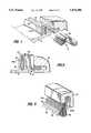
- FIG. 1is an enlarged fragmentary perspective view of a seal according to the present invention, employed between a transition piece and a first-stage nozzle in a combustor of a turbine;
- FIG. 2is an enlarged fragmentary cross-sectional view thereof
- FIG. 3is a fragmentary perspective view of a further embodiment of a seal according to the present invention.
- FIG. 4is a view similar to FIG. 3 illustrating a still further embodiment of the present invention.
- FIG. 5is a perspective view with parts broken out and in cross-section illustrating a seal according to the present invention employed for sealing between rotating and fixed parts;
- FIG. 6is a fragmentary view of a dual stiffness cloth brush seal according to the present invention formed between a combustor liner and transition piece;
- FIG. 7is a fragmentary perspective view with parts in cross-section of a seal in accordance with the present invention between two relatively movable parts;
- FIG. 8is a cross-sectional view thereof
- FIG. 9is a fragmentary view of a wear compensating brush/cloth seal and shaft with parts broken out and in cross-section for ease of illustration;
- FIG. 10is a side elevational view of the seal illustrated in FIG. 9;
- FIG. 11is a fragmentary perspective view with parts broken out and in cross-section of a hybrid labyrinth brush seal according to the present invention.
- FIG. 12is a reduced fragmentary cross-sectional view thereof.
- a sealconstructed in accordance with the present invention and applied to form a seal between a transition piece 12 of a combustor and a support 14 for a first-stage nozzle.
- the transition piece 12 and the first-stage support 14are movable relative to one another, in this instance, the movement of the transition piece 12 may be in both longitudinal and transverse directions, as well perpendicular to those directions. The movement also may be a pulsing movement.
- seal 10 of the present inventioncan be used in a wide variety of sealing applications, particularly for high-temperature use, and that the seal is not limited for use for sealing between the transition piece of a combustor and a support for a first-stage nozzle.
- the transition piece 12includes an upstanding groove formed by a pair of flanges 16 and 18 defining a slot therebetween.
- the first-stage nozzle support 14has a groove for receiving one flange of a generally Z-shaped support member which supports the seal in the groove, as illustrated in FIG. 2.
- the support member 20includes a channel 22 disposed on the opposite flange of the support 20 for securing the seal to the first-stage support 14 with the seal extending in the groove between flanges 16 and 18 for sealing between the transition piece and the first-stage nozzle support.
- the seal 10 illustrated in FIGS. 1 and 2comprises multiple layers 24 of woven material superposed directly one over the other.
- Marginal edges of the layersare suitably secured within the channel 22, for example, by welding, clamping and the like.
- the layersextend freely from the clamped margins thereof toward the opposite relatively movable part.
- the layers 24extend freely from the margins secured to the channel 22 and in this particular application, extend within the slot formed between flanges 16 and 18.
- the materials constituting the warp and weft of the woven clothmay comprise metal, polymer or ceramic bristles. Where metal bristles are employed, Inconel X750 or Haynes-25 may be used.
- the layers 24can accommodate to reasonable shape variations between the relatively moving parts, while simultaneously offering substantial sealing characteristics. That is, the woven materials allow for conformity to different surface movements and undulations that other seals, for example, labyrinth-type seals, cannot accommodate.
- the face of the woven materialmay seal against the flange of the slot.
- the forward and rear layers of the woven material, designated 24a and 24bmay bear against the flanges 18 and 16, respectively, with the free margins of the layered woven material spaced from the base of the groove. Consequently, the flexibility of the layered woven materials permits these materials to follow the movements and undulations of the relatively moving parts while simultaneously maintaining an effective seal between the parts.
- the seal hereofmay also comprise a hybrid between brush seals and seals formed of woven materials.
- FIG. 3there is illustrated a hybrid seal of this type wherein there are provided forward and rearward layers of woven material 24c and 24d between which there is sandwiched a plurality of free bristles 28.
- the bristlesmay be employed much in the same way as brush seals are employed in the seal but between layers of woven material.
- the ends of the bristlesare secured within the channel 22, for example, by welding, to project from the channel freely similarly with the forward and rearward woven materials 24c and 24d.
- the sealmay be formed by one or both of the faces of the woven material bearing against a sealing member such as the flanges 18 and 16.
- the bristles of the woven layers which extend in a direction parallel to the margin which is securedmay terminate short of the free edges of the perpendicularly disposed bristles in the woven layers.
- the transversely extending bristles 30 in the forward layer 24care set back from the free ends 32 of the longitudinally extending bristles 34 forming part of the woven material.
- some of the advantages of standard brush sealsare obtained by having the terminal portions of the longitudinally extending bristles extending freely from the woven cloth, thus affording the advantage of brush seals without the disadvantage of handling loose, free bristles during manufacture to form brush seals.
- the set-back of the transversely extending bristlescan be used in both the layered woven materials forming the seal illustrated in FIGS. 1 and 2, as well as the hybrid woven material/brush seals illustrated in FIGS. 3-4.
- FIG. 4there is illustrated another form of seal hereof wherein multiple layers 36 of woven materials are interspersed with free bristles 38. That is, a plurality of free bristles 38 are disposed between each adjacent pairs of woven material layers 36 in order to combine the advantages of both brush seals formed by free bristles and woven seals.
- the transversely extending bristles of the layersare set back from the free edge of the seal whereby the free edge of the seal is essentially formed of freely extending bristles.
- FIG. 5there is illustrated a seal according to the present invention, sealing between relatively rotating parts, for example, a rotating shaft 40 and a fixed frame 42.
- the fixed frame 42may be in the shape of an annular channel about shaft 40.
- the layers of woven materialare spin-woven to provide substantially radially extending bristles 44 and bristles 46 concentric about the axis of shaft 40.
- the bristles 46as illustrated, may be set back from the free end of bristles 44.
- any one of the previously described embodimentsmay be used in the context of forming a seal of this type between relatively rotating parts.
- the bristles forming the woven materialsmay be different in gauge and type of material from one another.
- the sealincludes a pack of long woven metal/polymer/ceramic cloth strips comprising stiff brush bristle fibers 56 extending from a strip of woven fibers.
- the fibers 56comprise a cross-weave and fibers 58 comprise softer, more pliable fibers in an orthogonal direction, i.e., a longitudinal weave.
- the bristles 56extend from the weave at an angle, for example, about 10°-30° .
- the woven edge of the fibersis wrapped about the outside of the liner, as illustrated.
- a metal ribbon 60is suitably secured, for example, by bolting or welding, to secure the seal in place with the tips of the bristles 56 projecting outwardly for engagement along the inside surface of transition piece 54.
- FIGS. 7 and 8there is illustrated a similar seal as in FIG. 6.
- a pack of woven metal/polymer/ceramic woven stripscomprising stiff bristle fibers 62 extending in one direction, i.e., a cross-weave direction, and softer, more pliable fibers 64 extending in an orthogonal direction, i.e., longitudinal weave, are provided.
- the brush bristles 62extend from the woven part 65 of the woven strip and are held together by the weave of the strip.
- the bristles 62With the free ends of the bristles 62 projecting from the woven strip and the woven strip secured to one of the movable parts, the bristles 62 can be bent to a desired angle and cut to form a sealing contact with a mating surface.
- the mating surfaceas illustrated in FIG. 7 at 66, can be non-uniform, i.e., wavy or undulating.
- This type of sealis effective to seal between substantial pressure differences, while permitting differential motions between the sealed parts.
- this type of sealmay be used between the transition piece and first-stage nozzle of a turbine.
- no special shapes for the sealsare required in order to fit the seals for sealing engagement against variably shaped bodies and with relative motions in substantially any direction.
- the foregoing-described sealallows for odd shapes to be easily conformed to by a pack of such strips cut from a standard strip stock.
- the conformityis achieved by the relatively softer fibers of the longitudinal weave with the stiffer bristles extending orthogonally from the softer fibers, sealing in the nature of brush seals.
- a seal for sealing across an interface having very high pressure differentialsmay be used in inter-stage sealing in a high compression ratio compressor.
- Labyrinth sealshave been used in these situations in the past but do not readily conform to vibrating or rotating surfaces or imperfections in those surfaces. Their effectiveness also diminishes as the pressure differential across the seal is increased.
- Brush sealshave normal wear problems, generally resulting over time in loss of pressure and leakage.
- the brush bristles or the bristles extending from the weaveare held in a frame 70 and project radially inwardly such that the tips of the bristles contact the shaft 72.
- the frame 70includes a flange 74 on one side to accommodate the bending of the bristles in one direction, as indicated by the dashed lines, in response to wear and differential pressure across the seal.
- the shaft 72includes a collar 75 having a curved surface 76 on the same side of the frame 70 as the flange 74.
- the differential pressurecauses the bristles to bear against the curved surface of collar 75 such that the tips seal against a higher point along the collar surface 76.
- the curvature of the surface 76 and the length of the bristles projecting from frame 70is such that the curvature of the surface 76 increases with increasing distance away from the initial contact point of the bristles with the shaft surface. Hence, any shortening of the bristles due to wear is accommodated by the closer proximity of the curved surface 76 to the base of the bristles in frame 70.
- FIGS. 11 and 12there is illustrated a combination hybrid labyrinth brush seal.
- labyrinth sealsdo not readily conform to vibrating or rotating surfaces, particularly where imperfections are extant. Brush seals conform to imperfections and seal better than labyrinths but require a backing frame.
- a combination hybrid labyrinth brush sealwhich readily and easily conforms to the surfaces being sealed, while inherently providing a backing for the brush seals.
- FIG. 11there is illustrated a labyrinth seal comprised of a sealing member 80 having sets of radially inwardly directed flanges 82 and 83 which cooperate with teeth 84 and 85 formed on shaft 86 to form a labyrinth seal.
- Foreshortened flanges 87 and 88project radially inwardly from member 80 and form annular channels with flanges 82 and 83, respectively, for receiving brush seal packs 90.
- the radially inwardly directed tips of the brush seal packsseal against the surface of the shaft without detracting from the effectiveness of the labyrinth seals.
- the brush seal packs 90are, of course, secured between the flanges 82, 87 and 83, 88, respectively.
- the flangesthus provide a backing for the brush seals affording structural stability to the seals.
- the brush seal packsmay comprise solely a plurality of bristles projecting radially from the channels.
- woven seals as illustrated in FIG. 1 or hybrid woven/brush seal combinationsmay be used in this form of the present invention.
Landscapes
- Engineering & Computer Science (AREA)
- General Engineering & Computer Science (AREA)
- Mechanical Engineering (AREA)
- Turbine Rotor Nozzle Sealing (AREA)
- Sealing Devices (AREA)
- Sealing Using Fluids, Sealing Without Contact, And Removal Of Oil (AREA)
Abstract
Description
This is a continuation of application Ser. No. 07/978,731, filed Nov. 19, 1992, now abandoned.
The present invention relates to seals for turbine applications and particularly relates to woven seals and hybrid cloth-brush seals for sealing between relatively moving parts in gas turbines.
Sealing is oftentimes essential when there are two relatively movable mechanical members in close proximity to one another. The members may have substantial relative motion, such as a turbine shaft against a lubricating oil reservoir, or a rotatable turbine stage relative to fixed support structure and having to withstand a pressure differential across the stage. Alternatively, there could be small vibratory pulsing motion between the members, along with thermal growth, as in sealing between a combustor and a transition piece. The resultant dynamic mismatch at typical combustor junctions requires an effective seal to contain the combustion products and a pressure differential and to allow for the dimensional growth.
More particularly, a plurality of combustors are conventionally disposed in an annular array about the axis of a turbine. Hot gases of combustion flow from each combustor through a transition piece into the first-stage nozzle. Because the transition pieces and the first-stage nozzle are formed of different materials and are subjected to different temperatures during operation, they experience different degrees of thermal growth. Thus, both the transition pieces and the first-stage nozzle support elements move radially, circumferentially and axially relative to one another as a result of thermal growth. Dynamic pulsing between these parts also occurs. This time variable mismatch at the junction of the transition pieces and the first-stage nozzle support elements requires an effective seal to contain the combustion products and the pressure differential across the space, while accommodating these dimensional changes. More particularly, the sealing devices have to conform to surfaces that have time varying characteristics, including whirl, wobble and surface undulations introduced due to wear, and must be capable of operating under high temperature conditions.
A substantial number of seals have been employed in turbine applications in the past. For example, labyrinth seals are often employed between relatively rotating parts. Labyrinth seals, however, have limitations in that they do not easily conform to vibratory movement or rotating surfaces, particularly if there are imperfections in the surfaces. Labyrinth seals have not demonstrated usefulness in non-rotary applications. Brush seals have been used in many environments, including turbines. Brush seals generally conform better to surface non-uniformities and seal better than labyrinth seals. However, they are severely limited by handling and fabrication difficulties. For example, the very fine bristle wires are not bound together before assembly and it is a formidable task to lay out a predetermined layer of bristles to the required thickness to form a bristle pack suitable to form the resulting seal. The brush seals are, thus, very expensive.
According to an aspect of the present invention, there is provided a cloth seal comprised of a plurality of layers of woven material, such as metal, polymer or ceramic material, which are superposed over one another, bound together along an edge in a suitable frame and from which the layers project to seal with an adjacent part. Because of the flexible nature of the layered woven material, it can conform to the surfaces of the adjacent part and form an effective seal. For example, in a seal formed between a transition piece and a first-stage nozzle element, the layers of material may be disposed in a frame and suitably secured thereto, for example, by clamping the frame, welding the material to the frame, or the like. The layers of material would project from the frame to the transition piece. As well known, tile transition piece moves in a pulsed fashion having both longitudinal and transverse movements. With the free edge of the layers engaging the transition piece, an effective seal is formed between these high and low-pressure areas. The woven material along its sealing edge may have free bristles projecting from the weave, i.e., the transversely extending bristles may be spaced back from the tips of the longitudinally extending bristles whereby the latter form free bristles along the sealing edge of the woven material.
In an alternate form hereof, there is provided a hybrid woven material in combination with brush seals. For example, layers of the woven material may be interspersed with discrete bristles or brushes whereby a combination brush and woven material seal is formed.
In a further alternative form of the present invention, there is provided a dual stiffness cloth brush seal for sealing between a combustion liner and transition piece. The seal comprises a pack of long, woven metal/polymer/ceramic cloth strips having stiff bristle fibers extending in one direction and a softer, more pliable plurality of fibers extending in the orthogonal direction. The stiff bristles may be bent at an angle, for example, on the order of 10° to 30° . In use, the cloth end, i.e., the more compliant longitudinal weave, may be wrapped around the outside of the combustion liner and a metal ribbon may overlie the seal, securing it to the liner. The bristles project outwardly at the desired angle for engagement at their ends with the inside surface of the transition piece, forming a seal.
In a further embodiment of the present invention, the seal hereof may be used for shaft sealing applications where high-pressure differentials have to be tolerated. For example, the woven seal may be clamped in a backing plate, with the bristles extending radially toward and into engagement with the rotatable shaft. By providing a curved surface on the downstream low-pressure side of the seal, the wear of the bristles on the shaft can be accommodated as they bear along the curved surface. That is, as the bristles wear, the bristles bend such that the tips continue to engage the curved surface of the shaft and continue to afford a sealing function. Thus, for high pressure differentials across a sealing interface, the bristles afford a superior sealing mechanism that does not lose its effectiveness with use, particularly when the seal material, i.e., the bristles, are worn.
In a still further embodiment of the present invention, there is provided a hybrid labyrinth-brush seal particularly for sealing between a shaft and a fixed member. As well known, shaft sealing using labyrinth seals alone results in leakage past the sealing fins. Excessive wear also occurs should the labyrinth seal fins contact one another. In accordance with the present invention, a brush seal or a woven cloth with bristles extending therefrom may be clamped in a slot between the labyrinth seals. Thus, with one of the labyrinth seals serving as a backing for the brush seal, the brushes engage the rotating shaft, affording improved sealing with the brush seal, higher structural integrity and added sealing with the labyrinth. Furthermore, this type of seal can be retrofitted into existing labyrinth seals.
These forms of woven material seals or hybrid woven material/brush seals may accommodate reasonable shape variations, while offering superior sealing. They can be formed of high-temperature resistant materials and offer substantial structural integrity by tying in the fibers or bristles into a weave, yet allowing for conformity to different surface movements and undulations that other types of seals, for example, labyrinth seals, would not be able to accommodate.
In a preferred embodiment according to the present invention, there is provided a seal comprising first and second relatively moving parts, a plurality of layers of a woven material substantially overlying one another with overlying marginal portions freely engaging the first part to form a seal therewith and means for securing the layers of woven material to the second part, with the woven material of the layers thereof projecting from the second part and between the first and second parts to form a seal.
In a further preferred embodiment according to the present invention, there is provided a seal comprising first and second parts relatively rotating about an axis, at least one fin disposed on each part and projecting radially toward the other part at axially spaced positions along the parts to define a labyrinth seal between the parts and an annular array of a plurality of bristles carried by one of the first and second parts and extending generally radially toward another of the first and second parts. Means secure the bristles to the one part adjacent the fin carried thereby such that free ends thereof project from the one part for sealing engagement against another part whereby a combined labyrinth and brush seal is formed.
Accordingly, it is a primary object of the present invention to provide a novel and improved woven seal and hybrid cloth brush seals for turbine applications for sealing between relatively moving parts in a manner which accommodates differently shaped surfaces and different relative motions of moving surfaces.
FIG. 1 is an enlarged fragmentary perspective view of a seal according to the present invention, employed between a transition piece and a first-stage nozzle in a combustor of a turbine;
FIG. 2 is an enlarged fragmentary cross-sectional view thereof;
FIG. 3 is a fragmentary perspective view of a further embodiment of a seal according to the present invention;
FIG. 4 is a view similar to FIG. 3 illustrating a still further embodiment of the present invention;
FIG. 5 is a perspective view with parts broken out and in cross-section illustrating a seal according to the present invention employed for sealing between rotating and fixed parts;
FIG. 6 is a fragmentary view of a dual stiffness cloth brush seal according to the present invention formed between a combustor liner and transition piece;
FIG. 7 is a fragmentary perspective view with parts in cross-section of a seal in accordance with the present invention between two relatively movable parts;
FIG. 8 is a cross-sectional view thereof;
FIG. 9 is a fragmentary view of a wear compensating brush/cloth seal and shaft with parts broken out and in cross-section for ease of illustration;
FIG. 10 is a side elevational view of the seal illustrated in FIG. 9;
FIG. 11 is a fragmentary perspective view with parts broken out and in cross-section of a hybrid labyrinth brush seal according to the present invention; and
FIG. 12 is a reduced fragmentary cross-sectional view thereof.
Reference will now be made in detail to a present preferred embodiment of the invention, an example of which is illustrated in the accompanying drawings.
Referring now to FIG. 1, there is illustrated a seal, generally designated 10, constructed in accordance with the present invention and applied to form a seal between atransition piece 12 of a combustor and asupport 14 for a first-stage nozzle. It will be appreciated that thetransition piece 12 and the first-stage support 14 are movable relative to one another, in this instance, the movement of thetransition piece 12 may be in both longitudinal and transverse directions, as well perpendicular to those directions. The movement also may be a pulsing movement. It will be appreciated that other types of movements between relatively moving parts can be accommodated by theseal 10 of the present invention, that theseal 10 can be used in a wide variety of sealing applications, particularly for high-temperature use, and that the seal is not limited for use for sealing between the transition piece of a combustor and a support for a first-stage nozzle.
Referring again to FIG. 1, thetransition piece 12 includes an upstanding groove formed by a pair offlanges stage nozzle support 14 has a groove for receiving one flange of a generally Z-shaped support member which supports the seal in the groove, as illustrated in FIG. 2. Thesupport member 20 includes achannel 22 disposed on the opposite flange of thesupport 20 for securing the seal to the first-stage support 14 with the seal extending in the groove betweenflanges
Theseal 10 illustrated in FIGS. 1 and 2 comprisesmultiple layers 24 of woven material superposed directly one over the other. Marginal edges of the layers are suitably secured within thechannel 22, for example, by welding, clamping and the like. The layers extend freely from the clamped margins thereof toward the opposite relatively movable part. Thus, thelayers 24 extend freely from the margins secured to thechannel 22 and in this particular application, extend within the slot formed betweenflanges layers 24 can accommodate to reasonable shape variations between the relatively moving parts, while simultaneously offering substantial sealing characteristics. That is, the woven materials allow for conformity to different surface movements and undulations that other seals, for example, labyrinth-type seals, cannot accommodate. In the illustrated application of theseal 10 hereof to sealing between the transition piece and the first-stage nozzle support, the face of the woven material may seal against the flange of the slot. For example, as illustrated in FIG. 2, the forward and rear layers of the woven material, designated 24a and 24b, may bear against theflanges
The seal hereof may also comprise a hybrid between brush seals and seals formed of woven materials. For example, in FIG. 3, there is illustrated a hybrid seal of this type wherein there are provided forward and rearward layers of wovenmaterial 24c and 24d between which there is sandwiched a plurality offree bristles 28. The bristles may be employed much in the same way as brush seals are employed in the seal but between layers of woven material. The ends of the bristles are secured within thechannel 22, for example, by welding, to project from the channel freely similarly with the forward and rearward wovenmaterials 24c and 24d. Here, again, the seal may be formed by one or both of the faces of the woven material bearing against a sealing member such as theflanges
As illustrated in both forms shown in FIGS. 3 and 4, the bristles of the woven layers which extend in a direction parallel to the margin which is secured, may terminate short of the free edges of the perpendicularly disposed bristles in the woven layers. Thus, as illustrated in FIG. 3, the transversely extending bristles 30 in the forward layer 24c are set back from the free ends 32 of thelongitudinally extending bristles 34 forming part of the woven material. In this manner, some of the advantages of standard brush seals are obtained by having the terminal portions of the longitudinally extending bristles extending freely from the woven cloth, thus affording the advantage of brush seals without the disadvantage of handling loose, free bristles during manufacture to form brush seals. It will be appreciated that the set-back of the transversely extending bristles can be used in both the layered woven materials forming the seal illustrated in FIGS. 1 and 2, as well as the hybrid woven material/brush seals illustrated in FIGS. 3-4.
Referring now to FIG. 4, there is illustrated another form of seal hereof whereinmultiple layers 36 of woven materials are interspersed withfree bristles 38. That is, a plurality offree bristles 38 are disposed between each adjacent pairs of woven material layers 36 in order to combine the advantages of both brush seals formed by free bristles and woven seals. In FIG. 4, the transversely extending bristles of the layers are set back from the free edge of the seal whereby the free edge of the seal is essentially formed of freely extending bristles.
Referring now to FIG. 5, there is illustrated a seal according to the present invention, sealing between relatively rotating parts, for example, a rotatingshaft 40 and a fixedframe 42. The fixedframe 42 may be in the shape of an annular channel aboutshaft 40. In this form, the layers of woven material are spin-woven to provide substantially radially extendingbristles 44 and bristles 46 concentric about the axis ofshaft 40. Thebristles 46, as illustrated, may be set back from the free end ofbristles 44. It will be appreciated that, while multiple layers of woven materials form the seal illustrated in FIG. 5, any one of the previously described embodiments may be used in the context of forming a seal of this type between relatively rotating parts.
It will also be appreciated that the bristles forming the woven materials may be different in gauge and type of material from one another. For example, for certain applications, it may be desirable to employ metal bristles in the woven material extending in one of the warp or weft directions, while employing a different type of material, such as a ceramic or a polymeric material extending in the other of the warp or weft directions.
Referring now to FIG. 6, there is illustrated a cloth brush seal, generally designated 50, and specifically configured to seal theliner 52 of a combustor and atransition piece 54. In this form, the seal includes a pack of long woven metal/polymer/ceramic cloth strips comprising stiff brush bristlefibers 56 extending from a strip of woven fibers. Particularly, thefibers 56 comprise a cross-weave andfibers 58 comprise softer, more pliable fibers in an orthogonal direction, i.e., a longitudinal weave. Thebristles 56 extend from the weave at an angle, for example, about 10°-30° . The woven edge of the fibers is wrapped about the outside of the liner, as illustrated. Ametal ribbon 60 is suitably secured, for example, by bolting or welding, to secure the seal in place with the tips of thebristles 56 projecting outwardly for engagement along the inside surface oftransition piece 54. By employing a seal of this type, leakage through this joint is substantially reduced, while simultaneously permitting differential motions between the transition piece and liner and with minimum wear.
Referring now to FIGS. 7 and 8, there is illustrated a similar seal as in FIG. 6. Particularly, a pack of woven metal/polymer/ceramic woven strips comprising stiff bristlefibers 62 extending in one direction, i.e., a cross-weave direction, and softer, morepliable fibers 64 extending in an orthogonal direction, i.e., longitudinal weave, are provided. The brush bristles 62 extend from thewoven part 65 of the woven strip and are held together by the weave of the strip. With the free ends of thebristles 62 projecting from the woven strip and the woven strip secured to one of the movable parts, thebristles 62 can be bent to a desired angle and cut to form a sealing contact with a mating surface. The mating surface, as illustrated in FIG. 7 at 66, can be non-uniform, i.e., wavy or undulating. This type of seal is effective to seal between substantial pressure differences, while permitting differential motions between the sealed parts. For example, this type of seal may be used between the transition piece and first-stage nozzle of a turbine. Thus, no special shapes for the seals are required in order to fit the seals for sealing engagement against variably shaped bodies and with relative motions in substantially any direction. The foregoing-described seal allows for odd shapes to be easily conformed to by a pack of such strips cut from a standard strip stock. The conformity is achieved by the relatively softer fibers of the longitudinal weave with the stiffer bristles extending orthogonally from the softer fibers, sealing in the nature of brush seals.
Referring now to FIGS. 9 and 10, there is provided a seal for sealing across an interface having very high pressure differentials. For example, this seal may be used in inter-stage sealing in a high compression ratio compressor. Labyrinth seals have been used in these situations in the past but do not readily conform to vibrating or rotating surfaces or imperfections in those surfaces. Their effectiveness also diminishes as the pressure differential across the seal is increased. Brush seals have normal wear problems, generally resulting over time in loss of pressure and leakage. In the seal of FIGS. 9 and 10, the brush bristles or the bristles extending from the weave are held in aframe 70 and project radially inwardly such that the tips of the bristles contact theshaft 72. Theframe 70 includes aflange 74 on one side to accommodate the bending of the bristles in one direction, as indicated by the dashed lines, in response to wear and differential pressure across the seal.
Theshaft 72 includes acollar 75 having acurved surface 76 on the same side of theframe 70 as theflange 74. In this manner, when the tips of the bristles wear, the differential pressure causes the bristles to bear against the curved surface ofcollar 75 such that the tips seal against a higher point along thecollar surface 76. Thus, a continuous sealing action is provided, notwithstanding wear of the brush bristles. The curvature of thesurface 76 and the length of the bristles projecting fromframe 70 is such that the curvature of thesurface 76 increases with increasing distance away from the initial contact point of the bristles with the shaft surface. Hence, any shortening of the bristles due to wear is accommodated by the closer proximity of thecurved surface 76 to the base of the bristles inframe 70.
Referring now to FIGS. 11 and 12, there is illustrated a combination hybrid labyrinth brush seal. As noted previously, labyrinth seals do not readily conform to vibrating or rotating surfaces, particularly where imperfections are extant. Brush seals conform to imperfections and seal better than labyrinths but require a backing frame. According to the present invention, there is provided a combination hybrid labyrinth brush seal which readily and easily conforms to the surfaces being sealed, while inherently providing a backing for the brush seals. Particularly, in FIG. 11, there is illustrated a labyrinth seal comprised of a sealingmember 80 having sets of radially inwardly directedflanges teeth shaft 86 to form a labyrinth seal.Foreshortened flanges member 80 and form annular channels withflanges flanges
The brush seal packs may comprise solely a plurality of bristles projecting radially from the channels. Alternately, woven seals as illustrated in FIG. 1 or hybrid woven/brush seal combinations may be used in this form of the present invention.
While the invention has been described with respect to what is presently regarded as the most practical embodiments thereof, it will be understood by those of ordinary skill in the art that various alterations and modifications may be made which nevertheless remain within the scope of the invention as defined by the claims which follow.
Claims (10)
1. A seal for sealing between a transition piece of a combustor and a support for a first stage nozzle of a turbine, comprising:
first and second relatively moving parts, said first part including a pair of flanges carried by the transition piece of the combustor and said second part including a channel carried by the first stage nozzle support;
a plurality of layers of a woven material adjacent one another, side face portions of said layers of said woven material freely engaging between and along the flanges of said first part, respectively, to form a seal therewith; and
means for securing said layers of woven material to said second part and within said channel, with said woven material of the layers thereof projecting from said second part and between said first and second parts to form a seal;
at least one of said woven layers including first and second sets of bristles extending generally perpendicular to one another in said woven layer thereof with said first set of bristles spaced back from ends of the bristles of said second set thereof to define free bristle portions of said second set of bristles extending from said first set of bristles with side face portions of said free bristle portions in free sealing engagement with said first part including one flange thereof, said first and second sets of bristles defining in part said side face portions of said one woven layer engaging said one flange of said first part to form said seal therewith.
2. A seal according to claim 1 including a plurality of bristles secured adjacent one end to said second part with said bristles extending freely from said second part between said adjacent layers of said woven material.
3. A seal according to claim 1 wherein one of said first and second sets of bristles is formed of metal.
4. A seal according to claim 1 wherein one of said first and second sets of bristles is formed of a ceramic material.
5. A seal according to claim 1 wherein one of said first and second sets of bristles is formed of a polymeric material.
6. A seal according to claim 1 wherein said bristles of said woven layers are formed of different materials.
7. A seal according to claim 1 wherein said first and second sets of bristles are formed of different gauge.
8. A seal according to claim 1 wherein one of said first and second parts is movable relative to another of said first and second parts, the latter part being stationary.
9. A seal according to claim 1 wherein one of said first and second parts is rotatable relative to another of said first and second parts, the latter part being stationary.
10. A seal according to claim 9 wherein said woven layers are comprised of spin-woven bristles with a plurality of said bristles extending radially.
Priority Applications (9)
| Application Number | Priority Date | Filing Date | Title |
|---|---|---|---|
| US08/342,011US5474306A (en) | 1992-11-19 | 1994-11-16 | Woven seal and hybrid cloth-brush seals for turbine applications |
| US08/438,228US6010132A (en) | 1992-11-19 | 1995-05-09 | Hybrid labyrinth and cloth-brush seals for turbine applications |
| US08/719,667US5749584A (en) | 1992-11-19 | 1996-09-25 | Combined brush seal and labyrinth seal segment for rotary machines |
| US08/839,737US6257586B1 (en) | 1992-11-19 | 1997-04-15 | Combined brush seal and labyrinth seal segment for rotary machines |
| US08/855,013US6131910A (en) | 1992-11-19 | 1997-05-13 | Brush seals and combined labyrinth and brush seals for rotary machines |
| US08/856,291US6042119A (en) | 1992-11-19 | 1997-05-14 | Woven seals and hybrid cloth-brush seals for turbine applications |
| US09/027,128US6131911A (en) | 1992-11-19 | 1998-02-20 | Brush seals and combined labyrinth and brush seals for rotary machines |
| US09/081,091US6173958B1 (en) | 1992-11-19 | 1998-05-19 | Hybrid labyrinth and cloth-brush seals for turbine applications |
| US09/791,881US6435513B2 (en) | 1992-11-19 | 2001-02-26 | Combined brush seal and labyrinth seal segment for rotary machines |
Applications Claiming Priority (2)
| Application Number | Priority Date | Filing Date | Title |
|---|---|---|---|
| US97873192A | 1992-11-19 | 1992-11-19 | |
| US08/342,011US5474306A (en) | 1992-11-19 | 1994-11-16 | Woven seal and hybrid cloth-brush seals for turbine applications |
Related Parent Applications (2)
| Application Number | Title | Priority Date | Filing Date |
|---|---|---|---|
| US07/978,371ContinuationUS5375050A (en) | 1991-11-18 | 1992-11-18 | Electric power converter arrangement and electric rolling stock control device using the same |
| US97873192AContinuation | 1992-11-19 | 1992-11-19 |
Related Child Applications (1)
| Application Number | Title | Priority Date | Filing Date |
|---|---|---|---|
| US08/438,228DivisionUS6010132A (en) | 1992-11-19 | 1995-05-09 | Hybrid labyrinth and cloth-brush seals for turbine applications |
Publications (1)
| Publication Number | Publication Date |
|---|---|
| US5474306Atrue US5474306A (en) | 1995-12-12 |
Family
ID=25526343
Family Applications (4)
| Application Number | Title | Priority Date | Filing Date |
|---|---|---|---|
| US08/342,011Expired - LifetimeUS5474306A (en) | 1992-11-19 | 1994-11-16 | Woven seal and hybrid cloth-brush seals for turbine applications |
| US08/438,228Expired - Fee RelatedUS6010132A (en) | 1992-11-19 | 1995-05-09 | Hybrid labyrinth and cloth-brush seals for turbine applications |
| US08/856,291Expired - Fee RelatedUS6042119A (en) | 1992-11-19 | 1997-05-14 | Woven seals and hybrid cloth-brush seals for turbine applications |
| US09/081,091Expired - Fee RelatedUS6173958B1 (en) | 1992-11-19 | 1998-05-19 | Hybrid labyrinth and cloth-brush seals for turbine applications |
Family Applications After (3)
| Application Number | Title | Priority Date | Filing Date |
|---|---|---|---|
| US08/438,228Expired - Fee RelatedUS6010132A (en) | 1992-11-19 | 1995-05-09 | Hybrid labyrinth and cloth-brush seals for turbine applications |
| US08/856,291Expired - Fee RelatedUS6042119A (en) | 1992-11-19 | 1997-05-14 | Woven seals and hybrid cloth-brush seals for turbine applications |
| US09/081,091Expired - Fee RelatedUS6173958B1 (en) | 1992-11-19 | 1998-05-19 | Hybrid labyrinth and cloth-brush seals for turbine applications |
Country Status (1)
| Country | Link |
|---|---|
| US (4) | US5474306A (en) |
Cited By (93)
| Publication number | Priority date | Publication date | Assignee | Title |
|---|---|---|---|---|
| US5613829A (en)* | 1996-05-03 | 1997-03-25 | General Electric Company | Gas turbine subassembly having a brush seal |
| EP0765619A1 (en)* | 1995-09-28 | 1997-04-02 | United Technologies Corporation | Method of manufacturing a brush seal |
| WO1997042399A1 (en)* | 1996-05-08 | 1997-11-13 | MTU MOTOREN- UND TURBINEN-UNION MüNCHEN GMBH | Brush seal |
| US5749584A (en)* | 1992-11-19 | 1998-05-12 | General Electric Company | Combined brush seal and labyrinth seal segment for rotary machines |
| DE19645163A1 (en)* | 1996-11-02 | 1998-05-14 | Mtu Muenchen Gmbh | Brush seal for rotor-stator arrangement |
| US5752805A (en)* | 1995-07-28 | 1998-05-19 | Mtu Motoren- Und Turbinen-Union | Brush seal for turbo-engines |
| DE19712088A1 (en)* | 1997-03-22 | 1998-10-01 | Mtu Muenchen Gmbh | Brush seal with bristles inclined in the circumferential direction |
| EP0903519A1 (en)* | 1997-09-22 | 1999-03-24 | General Electric Company | Flexible cloth seal assembly |
| US5941685A (en)* | 1997-10-14 | 1999-08-24 | General Electric Company | Brush seal for use on bumpy rotating surfaces |
| US5961125A (en)* | 1997-10-02 | 1999-10-05 | General Electric Company | Brush seal for use on rough rotating surfaces |
| US5975535A (en)* | 1996-10-02 | 1999-11-02 | Mtu Motoren-Und Turbinen-Union Muenchen Gmbh | Brush seal between a rotor and a stator in a turbine machine |
| US6010132A (en)* | 1992-11-19 | 2000-01-04 | General Electric Co. | Hybrid labyrinth and cloth-brush seals for turbine applications |
| US6012723A (en)* | 1996-10-04 | 2000-01-11 | Asea Brown Boveri Ag | Brush gasket |
| US6027121A (en)* | 1997-10-23 | 2000-02-22 | General Electric Co. | Combined brush/labyrinth seal for rotary machines |
| US6045134A (en)* | 1998-02-04 | 2000-04-04 | General Electric Co. | Combined labyrinth and brush seals for rotary machines |
| EP0992721A1 (en)* | 1998-10-08 | 2000-04-12 | ROLLS-ROYCE plc | Improved brush seal |
| US6065756A (en)* | 1997-12-10 | 2000-05-23 | General Electric Co. | Flex seal for gas turbine expansion joints |
| WO2000047919A1 (en) | 1999-02-09 | 2000-08-17 | General Electric Company | Combined labyrinth and brush seals for rotary machines |
| US6105966A (en)* | 1998-08-10 | 2000-08-22 | General Electric Company | Brush seal segment |
| US6131910A (en)* | 1992-11-19 | 2000-10-17 | General Electric Co. | Brush seals and combined labyrinth and brush seals for rotary machines |
| US6131911A (en)* | 1992-11-19 | 2000-10-17 | General Electric Co. | Brush seals and combined labyrinth and brush seals for rotary machines |
| US6139018A (en)* | 1998-03-25 | 2000-10-31 | General Electric Co. | Positive pressure-actuated brush seal |
| US6168162B1 (en) | 1998-08-05 | 2001-01-02 | General Electric Co. | Self-centering brush seal |
| US6168377B1 (en) | 1999-01-27 | 2001-01-02 | General Electric Co. | Method and apparatus for eliminating thermal bowing of steam turbine rotors |
| US6250640B1 (en) | 1998-08-17 | 2001-06-26 | General Electric Co. | Brush seals for steam turbine applications |
| US6257588B1 (en)* | 1998-09-22 | 2001-07-10 | General Electric Company | Brush seal and rotary machine including such brush seal |
| US6290232B1 (en) | 1999-11-16 | 2001-09-18 | General Electric Co. | Rub-tolerant brush seal for turbine rotors and methods of installation |
| WO2001076348A2 (en) | 2000-04-06 | 2001-10-18 | Turbocare Inc. | Improved brush-seal designs for turbines and similar rotary apparatus |
| US6331006B1 (en) | 2000-01-25 | 2001-12-18 | General Electric Company | Brush seal mounting in supporting groove using flat spring with bifurcated end |
| EP1052438A3 (en)* | 1999-05-13 | 2002-02-06 | General Electric Company | Brush seal segment with bristle damping |
| EP1239118A2 (en) | 2001-03-05 | 2002-09-11 | General Electric Company | Flexible cloth seal for turbine combustors |
| US6502825B2 (en) | 2000-12-26 | 2003-01-07 | General Electric Company | Pressure activated cloth seal |
| US6505835B2 (en)* | 2001-06-13 | 2003-01-14 | General Electric Company | Brush seals and methods of fabricating brush seals |
| US6508624B2 (en) | 2001-05-02 | 2003-01-21 | Siemens Automotive, Inc. | Turbomachine with double-faced rotor-shroud seal structure |
| US6547256B2 (en) | 2000-12-26 | 2003-04-15 | General Electric Company | Cloth ring seal |
| US6589012B2 (en) | 2001-09-24 | 2003-07-08 | General Electric Company | Method and apparatus for eliminating thermal bowing using brush seals in the diaphragm packing area of steam turbines |
| US6599089B2 (en) | 2001-12-28 | 2003-07-29 | General Electric Company | Supplemental seal for the chordal hinge seal in a gas turbine |
| US6609885B2 (en) | 2001-12-28 | 2003-08-26 | General Electric Company | Supplemental seal for the chordal hinge seal in a gas turbine |
| US6637751B2 (en)* | 2001-12-28 | 2003-10-28 | General Electric Company | Supplemental seal for the chordal hinge seals in a gas turbine |
| US6637752B2 (en)* | 2001-12-28 | 2003-10-28 | General Electric Company | Supplemental seal for the chordal hinge seal in a gas turbine |
| US6652231B2 (en) | 2002-01-17 | 2003-11-25 | General Electric Company | Cloth seal for an inner compressor discharge case and methods of locating the seal in situ |
| US6655913B2 (en) | 2002-01-15 | 2003-12-02 | General Electric Company | Composite tubular woven seal for an inner compressor discharge case |
| US6669202B1 (en) | 2002-06-27 | 2003-12-30 | General Electric Co. | Multi-core brush seal assembly for rotary machines |
| US20040101403A1 (en)* | 2002-11-22 | 2004-05-27 | Turnquist Norman Arnold | Brush seal arrangement for high pressure applications |
| EP1227219A3 (en)* | 1996-03-26 | 2004-09-29 | United Technologies Corporation | Method and apparatus for improving the air sealing effectiveness in a turbine engine |
| US6821086B1 (en) | 2003-06-03 | 2004-11-23 | General Electric Company | Turbomachine seal assembly and method therefor |
| US20050017458A1 (en)* | 2002-11-15 | 2005-01-27 | General Electric Company | Brush seal for static turbine components |
| US20050146095A1 (en)* | 2002-03-26 | 2005-07-07 | Siemens Aktiengesellschaft | Sealing assembly for a spindle |
| RU2258145C2 (en)* | 1999-10-04 | 2005-08-10 | Дженерал Электрик Компани | Method of and device for providing precise positioning of turbine brush seal in radial direction (versions) |
| US20060006603A1 (en)* | 1999-04-06 | 2006-01-12 | Dalton William S | Brush seal designs for turbines and similar rotary apparatus |
| US20070063448A1 (en)* | 2005-09-22 | 2007-03-22 | General Electric Company | Seals for turbines and turbo machinery |
| US20070069475A1 (en)* | 2005-09-29 | 2007-03-29 | General Electric Company | Pressure balanced brush seal |
| US20070079493A1 (en)* | 2005-09-29 | 2007-04-12 | General Electric Company | Method of manufacturing a brush seal for sealing between stationary and rotary components |
| CN1329633C (en)* | 2002-10-30 | 2007-08-01 | 通用电气公司 | Composite tubular woven seal for steam turbine diaphragm horizontal joint interfaces |
| US20070214628A1 (en)* | 2006-03-17 | 2007-09-20 | General Electric Company | Methods of manufacturing a segmented brush seal for sealing between stationary and rotary components |
| US20070252336A1 (en)* | 2004-08-11 | 2007-11-01 | Mtu Aero Engines Gmbh | Sealing Arrangement |
| US20080042365A1 (en)* | 2006-08-15 | 2008-02-21 | General Electric Company | Compliant plate seals for turbomachinery |
| EP2085575A1 (en)* | 2008-02-01 | 2009-08-05 | Siemens Aktiengesellschaft | Combination of a brush seal with piston ring for large seal gaps |
| US20090196742A1 (en)* | 2008-02-04 | 2009-08-06 | Turnquist Norman A | Retractable compliant plate seals |
| US20100064693A1 (en)* | 2008-09-15 | 2010-03-18 | Koenig Michael H | Combustor assembly comprising a combustor device, a transition duct and a flow conditioner |
| US20100143102A1 (en)* | 2008-02-18 | 2010-06-10 | General Electric Company | Compliant plate seal with self-correcting behavior |
| US20110005234A1 (en)* | 2008-02-27 | 2011-01-13 | Mitsubishi Heavy Industries, Ltd. | Connection structure of exhaust chamber, support structure of turbine, and gas turbine |
| US20110227289A1 (en)* | 2008-12-03 | 2011-09-22 | Mtu Aero Engines Gmbh | Brush seal |
| EP1559873A3 (en)* | 2004-01-28 | 2012-10-17 | Rolls-Royce Plc | Sealing arrangement for turbomachinery |
| US20120261386A1 (en)* | 2011-04-12 | 2012-10-18 | Fastrax Industries, Inc. | Non-Contact Rail Heater With Insulating Skirt |
| CN102865107A (en)* | 2011-07-07 | 2013-01-09 | 阿特拉斯·科普柯能源有限公司 | Axial shaft seal |
| US8382119B2 (en) | 2006-08-15 | 2013-02-26 | General Electric Company | Compliant plate seals for turbomachinery |
| US8398090B2 (en) | 2010-06-09 | 2013-03-19 | General Electric Company | Spring loaded seal assembly for turbines |
| US20130170979A1 (en)* | 2012-01-04 | 2013-07-04 | General Electric Company | Double ended brush seal assembly for a compressor |
| WO2013153866A1 (en)* | 2012-04-08 | 2013-10-17 | イーグル工業株式会社 | Brush seal |
| US8562000B2 (en) | 2011-05-20 | 2013-10-22 | Siemens Energy, Inc. | Turbine combustion system transition piece side seals |
| US20130341426A1 (en)* | 2012-02-10 | 2013-12-26 | United Technologies Corporation | Flexible leaf spring seal for sealing an air gap between moving plates |
| EP2738358A1 (en)* | 2012-11-29 | 2014-06-04 | General Electric Company | Turbomachine component including a seal member |
| US20140154060A1 (en)* | 2012-12-05 | 2014-06-05 | General Electric Company | Turbomachine seal assembly and method of sealing a rotor region of a turbomachine |
| GB2512164A (en)* | 2012-12-05 | 2014-09-24 | Snecma | Sealing of turbine engine enclosures produced by brush seal and labyrinth |
| EP2306009A3 (en)* | 2009-09-30 | 2014-10-15 | General Electric Company | A seal arrangement and a brush seal for a wind turbine |
| EP2853692A1 (en)* | 2013-09-25 | 2015-04-01 | MTU Aero Engines GmbH | Sealing element for an axial flow engine |
| JPWO2013153867A1 (en)* | 2012-04-08 | 2015-12-17 | イーグル工業株式会社 | Brush seal |
| US20160040600A1 (en)* | 2013-03-13 | 2016-02-11 | United Technologies Corporation | Multi-axial brush seal |
| US9366444B2 (en) | 2013-11-12 | 2016-06-14 | Siemens Energy, Inc. | Flexible component providing sealing connection |
| US9416969B2 (en) | 2013-03-14 | 2016-08-16 | Siemens Aktiengesellschaft | Gas turbine transition inlet ring adapter |
| US9470101B2 (en) | 2011-12-05 | 2016-10-18 | Nuovo Pignone S.P.A. | Turbomachine |
| RU2600478C2 (en)* | 2011-03-31 | 2016-10-20 | Дженерал Электрик Компани | Aspirating face seal, gas turbine engine having said seal, method of sealing of said engine and method of replacing secondary seal of said face seal (versions) |
| US20160333720A1 (en)* | 2014-01-28 | 2016-11-17 | United Technologies Corporation | Flexible small cavity seal for gas turbine engines |
| EP3148055A1 (en)* | 2015-09-28 | 2017-03-29 | Siemens Aktiengesellschaft | Electric machine, labyrinth seal for an electric machine and method for sealing of an electric machine |
| EP3055512A4 (en)* | 2013-10-11 | 2017-06-21 | United Technologies Corporation | Non-linearly deflecting brush seal land |
| US9702260B2 (en) | 2013-07-11 | 2017-07-11 | United Technologies Corporation | Stationary non-rotating brush seals |
| US9829106B2 (en)* | 2015-07-29 | 2017-11-28 | Siemens Energy, Inc. | Sealing arrangement for gas turbine transition pieces |
| US9879555B2 (en) | 2011-05-20 | 2018-01-30 | Siemens Energy, Inc. | Turbine combustion system transition seals |
| CN109642467A (en)* | 2016-06-22 | 2019-04-16 | 通用电气公司 | Turbine system with seal member |
| US11255206B2 (en)* | 2017-02-27 | 2022-02-22 | Rolls-Royce North American Technologies Inc. | Ceramic seal component for gas turbine engine and process of making the same |
| US20220113028A1 (en)* | 2020-10-09 | 2022-04-14 | Pratt & Whitney Canada Corp. | Combustor liner and method of operating same |
| US20250237149A1 (en)* | 2024-01-23 | 2025-07-24 | Turbo Powertech Co., Ltd. | Sealing device for power generating turbine |
Families Citing this family (55)
| Publication number | Priority date | Publication date | Assignee | Title |
|---|---|---|---|---|
| US6318728B1 (en)* | 1997-07-11 | 2001-11-20 | Demag Delaval Turbomachinery Corporation | Brush-seal designs for elastic fluid turbines |
| US5989224A (en)* | 1998-02-23 | 1999-11-23 | Dexide Corporation | Universal seal for use with endoscopic cannula |
| US6244599B1 (en)* | 1999-04-28 | 2001-06-12 | Flowserve Management Company | Floating brush seal |
| US6302646B1 (en)* | 1999-12-15 | 2001-10-16 | General Electric Company | Rotary machine containing a brush seal |
| US6595946B1 (en)* | 2000-02-25 | 2003-07-22 | United States Surgical Corporation | Valve assembly |
| US6471472B1 (en) | 2000-05-03 | 2002-10-29 | Siemens Canada Limited | Turbomachine shroud fibrous tip seal |
| WO2002036950A2 (en)* | 2000-11-06 | 2002-05-10 | Advanced Components And Materials, Inc. | Compliant brush shroud assembly for gas turbine engine compressors |
| US6880829B1 (en) | 2000-11-06 | 2005-04-19 | Advanced Components & Materials, Inc. | Compliant brush shroud assembly for gas turbine engine compressors |
| US6644667B2 (en) | 2001-02-23 | 2003-11-11 | Cmg Tech, Llc | Seal assembly and rotary machine containing such seal |
| US20100007093A1 (en)* | 2001-02-23 | 2010-01-14 | Grondahl Clayton M | Seal Assembly and Rotary Machine Containing Such Seal |
| US7578509B2 (en) | 2001-02-23 | 2009-08-25 | Cmg Tech, Llc | Seal assembly and rotary machine containing such seal |
| FR2824378B1 (en) | 2001-05-03 | 2003-10-10 | Snecma Moteurs | JOINT WITH BRUSHES IN COMPOSITE MATERIAL |
| US6547257B2 (en) | 2001-05-04 | 2003-04-15 | General Electric Company | Combination transition piece floating cloth seal and stage 1 turbine nozzle flexible sealing element |
| DE60218045T2 (en)* | 2001-07-06 | 2007-06-06 | R & D Dynamics Corp., Bloomfield | HYDRODYNAMIC FILM SEALING SEAL |
| US20030201608A1 (en)* | 2002-04-25 | 2003-10-30 | United Technologies Corporation | Brush seal with fewer parts |
| DE10259381A1 (en)* | 2002-12-18 | 2004-07-15 | Mtu Aero Engines Gmbh | sealing arrangement |
| US20040180595A1 (en)* | 2003-03-11 | 2004-09-16 | Matthew Arold-Gorham | Woven brush with base for forming site seal |
| US20090072486A1 (en)* | 2004-05-04 | 2009-03-19 | Rexnord Industries, Llc | Brush seal |
| US20070187900A1 (en)* | 2004-05-04 | 2007-08-16 | Advanced Components & Materials, Inc. | Non-metallic brush seals |
| US20080284107A1 (en)* | 2004-05-04 | 2008-11-20 | Flaherty Andrew L | Ceramic Brush Seals |
| US7367567B2 (en) | 2005-03-02 | 2008-05-06 | United Technologies Corporation | Low leakage finger seal |
| DE102005042272A1 (en)* | 2005-09-06 | 2007-03-08 | Mtu Aero Engines Gmbh | Turbomachine and sealing element for a turbomachine |
| RU2301897C1 (en)* | 2005-11-24 | 2007-06-27 | Открытое акционерное общество "Силовые машины-ЗТЛ, ЛМЗ, Электросила, Энергомашэкспорт" (ОАО "Силовые машины") | Device for noncontact sealing of turbomachine path flow |
| US20080001363A1 (en)* | 2006-06-28 | 2008-01-03 | General Electric Company | Brush sealing system and method for rotary machines |
| WO2008112432A2 (en)* | 2007-03-15 | 2008-09-18 | Rexnord Industries, Llc | Brush seal assembly and method of making |
| RU2347081C2 (en)* | 2007-04-02 | 2009-02-20 | Владимир Афанасьевич Синцов | Turbine seal from fluoropolymers |
| EP1992850A1 (en)* | 2007-05-18 | 2008-11-19 | Siemens Aktiengesellschaft | Brush seal |
| US7896153B2 (en)* | 2007-06-28 | 2011-03-01 | Aasef Shafik | Toilet utensil kit |
| US20090115141A1 (en)* | 2007-11-07 | 2009-05-07 | General Electric Company | Stage one nozzle to transition piece seal |
| ES2345310B1 (en)* | 2008-01-31 | 2011-07-22 | Airbus Operations, S.L. | SEALED FOR LABELED UNIONS AND ITS USE. |
| US8100405B2 (en)* | 2009-01-06 | 2012-01-24 | General Electric Company | System and method for providing compliant rotating seals |
| US8333544B1 (en)* | 2009-08-14 | 2012-12-18 | Florida Turbine Technologies, Inc. | Card seal for a turbomachine |
| US8596973B2 (en)* | 2009-12-07 | 2013-12-03 | Cmg Tech, Llc | Leaf seal assembly including polymer member and rotary machine containing such seal assembly |
| US9206904B2 (en) | 2010-07-08 | 2015-12-08 | Siemens Energy, Inc. | Seal including flexible seal strips |
| US8690158B2 (en)* | 2010-07-08 | 2014-04-08 | Siemens Energy, Inc. | Axially angled annular seals |
| US9255484B2 (en)* | 2011-03-16 | 2016-02-09 | General Electric Company | Aft frame and method for cooling aft frame |
| US9255486B2 (en) | 2011-03-28 | 2016-02-09 | General Electric Company | Rotating brush seal |
| US9121297B2 (en)* | 2011-03-28 | 2015-09-01 | General Electric Company | Rotating brush seal |
| DE102011083814A1 (en)* | 2011-09-30 | 2013-04-04 | Mtu Aero Engines Gmbh | Segmented component |
| EP2594790B1 (en) | 2011-11-17 | 2015-03-11 | ALSTOM Renewable Technologies | Sealing assembly |
| EP2959113B1 (en) | 2013-02-23 | 2018-10-31 | Rolls-Royce Corporation | Edge seal for gas turbine engine ceramic matrix composite component |
| DE102013217581A1 (en) | 2013-09-04 | 2015-03-05 | MTU Aero Engines AG | Sealing arrangement in an axial flow machine |
| CN104074558B (en)* | 2014-05-23 | 2016-01-20 | 浙江大学 | A kind of rotary brush labyrinth casing |
| US9322287B2 (en)* | 2014-06-03 | 2016-04-26 | General Electric Company | Brush seal for turbine |
| US10422239B2 (en) | 2015-03-18 | 2019-09-24 | Siemens Energy, Inc. | Seal assembly in a gas turbine engine |
| US9963992B2 (en)* | 2015-09-29 | 2018-05-08 | General Electric Company | Centrifugally activatable seal for a rotary machine and method of assembling same |
| US10233764B2 (en) | 2015-10-12 | 2019-03-19 | Rolls-Royce North American Technologies Inc. | Fabric seal and assembly for gas turbine engine |
| CN105839288B (en)* | 2016-05-12 | 2017-10-10 | 天津工业大学 | A kind of manufacture method of sealing brush and the sealing brush obtained by this method |
| BE1025092B1 (en)* | 2017-03-31 | 2018-10-29 | Safran Aero Boosters S.A. | BRUSH SEAL FOR TURBOMACHINE ROTOR |
| TR201705399A2 (en)* | 2017-04-11 | 2017-09-21 | Sdm Siradisi Arge Ve Muehendislik Sanayi Ticaret Anonim Sirketi | Knit fabric reinforced leaf felt |
| US11035470B2 (en) | 2018-04-05 | 2021-06-15 | Raytheon Technologies Corporation | Multi-plane brush seal |
| US10662797B2 (en) | 2018-04-05 | 2020-05-26 | Raytheon Technologies Corporation | Multi-plane brush seal |
| CN110657123B (en) | 2018-06-28 | 2024-03-26 | 丹佛斯公司 | Sealing device for refrigerant compressor |
| CN109578086B (en)* | 2018-11-08 | 2021-07-30 | 北京北冶功能材料有限公司 | Composite brush type sealing structure |
| US11261971B2 (en)* | 2019-11-11 | 2022-03-01 | Raytheon Technologies Corporation | Double angled brush seal |
Citations (27)
| Publication number | Priority date | Publication date | Assignee | Title |
|---|---|---|---|---|
| US2709338A (en)* | 1953-01-16 | 1955-05-31 | Rolls Royce | Double-walled ducting for conveying hot gas with means to interconnect the walls |
| US3186168A (en)* | 1962-09-11 | 1965-06-01 | Lucas Industries Ltd | Means for supporting the downstream end of a combustion chamber in a gas turbine engine |
| US3463498A (en)* | 1966-11-24 | 1969-08-26 | Rolls Royce | Fluid seal device |
| US3759038A (en)* | 1971-12-09 | 1973-09-18 | Westinghouse Electric Corp | Self aligning combustor and transition structure for a gas turbine |
| US4195476A (en)* | 1978-04-27 | 1980-04-01 | General Motors Corporation | Combustor construction |
| US4202554A (en)* | 1978-05-17 | 1980-05-13 | Rolls-Royce Limited | Brush seals |
| US4358120A (en)* | 1980-05-31 | 1982-11-09 | Rolls Royce Limited | Seals |
| US4415309A (en)* | 1980-03-01 | 1983-11-15 | Rolls-Royce Limited | Gas turbine engine seal |
| US4422288A (en)* | 1981-03-02 | 1983-12-27 | General Electric Company | Aft mounting system for combustion transition duct members |
| US4567730A (en)* | 1983-10-03 | 1986-02-04 | General Electric Company | Shielded combustor |
| US4580346A (en)* | 1982-04-24 | 1986-04-08 | Dr. Johannes Heidenhain Gmbh | Sealing strip for encapsulated measuring device |
| US4730876A (en)* | 1985-07-31 | 1988-03-15 | Motoren- Und Turbinen Union Munchen Gmbh | Apparatus for manufacturing a brush seal |
| US4781388A (en)* | 1985-04-20 | 1988-11-01 | MTU -Motoren-und Turbinen Union Munchen GmbH | Brush seal |
| US4785623A (en)* | 1987-12-09 | 1988-11-22 | United Technologies Corporation | Combustor seal and support |
| US4809990A (en)* | 1985-07-31 | 1989-03-07 | Motoren Und Turbinen Union Munchen Gmbh | Brush seals of ceramic material for thermal turbomachines |
| US4901522A (en)* | 1987-12-16 | 1990-02-20 | Societe Nationale D'etude Et De Construction De Moteurs D'aviation (Snecma) | Turbojet engine combustion chamber with a double wall converging zone |
| US4989886A (en)* | 1988-12-30 | 1991-02-05 | Textron Inc. | Braided filamentary sealing element |
| US5029875A (en)* | 1989-07-07 | 1991-07-09 | Textron Inc. | Fluid seal structure |
| EP0453315A1 (en)* | 1990-04-20 | 1991-10-23 | Cross Manufacturing Company (1938) Limited | Brush seals |
| US5074748A (en)* | 1990-07-30 | 1991-12-24 | General Electric Company | Seal assembly for segmented turbine engine structures |
| US5076590A (en)* | 1990-11-26 | 1991-12-31 | The United States Of America, As Represented By The Administrator Of The National Aeronautics And Space Administration | High temperature, flexible pressure-actuated, brush seal |
| US5090710A (en)* | 1987-05-29 | 1992-02-25 | Cross Manufacturing Company (1938) Limited | Brush seals |
| WO1992005378A1 (en)* | 1990-09-18 | 1992-04-02 | Cross Manufacturing Company (1938) Ltd. | Sealing devices |
| US5106104A (en)* | 1990-10-11 | 1992-04-21 | General Electric Company | Constant pressure drop multiple stage brush seal |
| US5114159A (en)* | 1991-08-05 | 1992-05-19 | United Technologies Corporation | Brush seal and damper |
| US5181827A (en)* | 1981-12-30 | 1993-01-26 | Rolls-Royce Plc | Gas turbine engine shroud ring mounting |
| US5201530A (en)* | 1991-10-18 | 1993-04-13 | United Technologies Corporation | Multi-layered brush seal |
Family Cites Families (55)
| Publication number | Priority date | Publication date | Assignee | Title |
|---|---|---|---|---|
| US768593A (en)* | 1903-03-24 | 1904-08-30 | Gen Electric | Turbine-generator. |
| US779785A (en)* | 1903-12-24 | 1905-01-10 | Gen Electric | Packing for elastic-fluid turbines. |
| US910472A (en)* | 1907-06-24 | 1909-01-19 | Gen Electric | Elastic-fluid turbine. |
| US957887A (en)* | 1908-09-28 | 1910-05-17 | Gen Electric | Packing for elastic-fluid-turbine shafts. |
| US980282A (en)* | 1909-07-26 | 1911-01-03 | Gen Electric | Leakage-reducing device for steam-turbines. |
| US1352277A (en)* | 1919-01-09 | 1920-09-07 | Gen Electric | Elastic-fluid turbine |
| US1352278A (en)* | 1920-03-03 | 1920-09-07 | Gen Electric | Elastic-fluid turbine |
| US1505647A (en)* | 1920-11-05 | 1924-08-19 | Gen Electric | Packing for elastic-fluid turbines and the like |
| US1594838A (en)* | 1921-08-29 | 1926-08-03 | Kegresse Adolphe | Dust cap |
| US1505924A (en)* | 1922-05-19 | 1924-08-19 | Gen Electric | Shaft packing for elastic-fluid turbines and the like |
| US1536014A (en)* | 1923-03-23 | 1925-04-28 | Gen Electric | Packing for elastic-fluid turbines and the like |
| US1689735A (en)* | 1923-10-05 | 1928-10-30 | Losel Franz | Labyrinth gland construction |
| US1651855A (en)* | 1924-06-24 | 1927-12-06 | Gen Electric | Elastic-fluid turbine |
| US1670071A (en)* | 1924-09-29 | 1928-05-15 | Gen Electric | Shaft packing |
| US1857961A (en)* | 1927-12-15 | 1932-05-10 | Westinghouse Electric & Mfg Co | Bi-metal packing |
| US1895930A (en)* | 1931-08-27 | 1933-01-31 | Gen Electric | Shaft packing |
| US2242673A (en)* | 1938-10-01 | 1941-05-20 | Westinghouse Electric & Mfg Co | Turbine gland |
| US2336323A (en)* | 1942-03-12 | 1943-12-07 | Gen Electric | Sealing arrangement for elastic fluid turbines and the like |
| US2543615A (en)* | 1947-04-24 | 1951-02-27 | Clark Bros Co Inc | Gas seal for rotating shafts |
| US2600991A (en)* | 1949-06-14 | 1952-06-17 | Gen Electric | Labyrinth seal arrangement |
| IT1063035B (en)* | 1975-05-09 | 1985-02-11 | Maschf Augsburg Nuernberg Ag | APPARATUS FOR REALIZING THE PROCEDURE TO ELEVATE THE DYNAMIC POWER LIMIT OF STEAM OR GAS TURBINES OR COMPRESSORS |
| DE2938484C2 (en)* | 1979-09-22 | 1982-06-16 | Fa. Carl Freudenberg, 6940 Weinheim | Sealing ring |
| ES8401591A1 (en)* | 1981-11-21 | 1983-11-16 | Crane Packing Ltd | Seals for liquid-tight closure between rotary component and partition |
| ZA834537B (en)* | 1982-06-30 | 1984-06-27 | Skf Uk Ltd | Seals for bearings |
| GB2191825B (en)* | 1986-06-18 | 1989-12-13 | Rolls Royce Plc | Means for retaining a brush seal in a housing |
| GB2198195B (en)* | 1986-12-06 | 1990-05-16 | Rolls Royce Plc | Brush seal |
| GB2212228B (en)* | 1987-11-13 | 1991-08-07 | Rolls Royce Plc | Enhanced performance brush seals |
| DE3812533A1 (en)* | 1988-04-15 | 1989-10-26 | Josef Seelen | SEAL FOR BLOW TUBE OR SHAFT |
| DE3828363A1 (en)* | 1988-08-20 | 1990-02-22 | Mtu Muenchen Gmbh | SEALING DEVICE |
| US5002288A (en)* | 1988-10-13 | 1991-03-26 | General Electric Company | Positive variable clearance labyrinth seal |
| US5029876A (en)* | 1988-12-14 | 1991-07-09 | General Electric Company | Labyrinth seal system |
| US5026075A (en)* | 1989-02-16 | 1991-06-25 | Westinghouse Electric Corp. | Radial seal |
| GB8907695D0 (en)* | 1989-04-05 | 1989-05-17 | Cross Mfg Co | Seals |
| JPH03209068A (en)* | 1990-01-10 | 1991-09-12 | Hitachi Ltd | Brush form seal |
| US5066025A (en)* | 1990-06-18 | 1991-11-19 | Hanrahan Paul R | Brush seal assembly |
| GB2250789B (en)* | 1990-12-12 | 1994-03-30 | Rolls Royce Plc | Brush seal arrangement |
| GB2250790B (en)* | 1990-12-12 | 1994-04-27 | Rolls Royce Plc | Brush seal |
| GB9103459D0 (en)* | 1991-02-19 | 1991-04-03 | Cross Mfg Co | Brush seal assembly |
| US5110033A (en)* | 1991-02-21 | 1992-05-05 | United Technologies Corporation | Segmented brush seal |
| US5176389A (en)* | 1991-02-21 | 1993-01-05 | United Technologies | Segmented brush seal |
| US5374068A (en)* | 1991-05-07 | 1994-12-20 | General Electric Co. | Method for providing uniform radial clearance of labyrinth seals between rotating and stationary components |
| US5181728A (en)* | 1991-09-23 | 1993-01-26 | General Electric Company | Trenched brush seal |
| FR2690493B1 (en) | 1992-04-23 | 1996-10-25 | Snecma | BRUSHED ANNULAR JOINT. |
| US5318309A (en)* | 1992-05-11 | 1994-06-07 | General Electric Company | Brush seal |
| US5400586A (en)* | 1992-07-28 | 1995-03-28 | General Electric Co. | Self-accommodating brush seal for gas turbine combustor |
| US5335920A (en)* | 1992-08-20 | 1994-08-09 | General Electric Company | Brush seal |
| US5474306A (en)* | 1992-11-19 | 1995-12-12 | General Electric Co. | Woven seal and hybrid cloth-brush seals for turbine applications |
| US5401036A (en)* | 1993-03-22 | 1995-03-28 | Eg & G Sealol, Inc. | Brush seal device having a recessed back plate |
| US5351971A (en)* | 1993-05-21 | 1994-10-04 | Eg&G Sealol, Inc. | Brush seal device having a floating backplate |
| US5524340A (en)* | 1994-09-13 | 1996-06-11 | General Electric Co. | Method for modifying a turbine diaphragm for use with a reduced rotor lan diameter |
| US5597167A (en)* | 1994-09-28 | 1997-01-28 | United Technologies Corporation | Brush seal with fool proofing and anti-rotation tab |
| US5509780A (en)* | 1995-03-08 | 1996-04-23 | General Electric Co. | Apparatus and method for providing uniform radial clearance of seals between rotating and stationary components |
| GB2301635B (en) | 1995-04-12 | 1998-09-16 | Gec Alsthom Ltd | Shaft seal arrangement |
| US5599026A (en)* | 1995-09-06 | 1997-02-04 | Innovative Technology, L.L.C. | Turbine seal with sealing strip and rubbing strip |
| US5630590A (en) | 1996-03-26 | 1997-05-20 | United Technologies Corporation | Method and apparatus for improving the airsealing effectiveness in a turbine engine |
- 1994
- 1994-11-16USUS08/342,011patent/US5474306A/ennot_activeExpired - Lifetime
- 1995
- 1995-05-09USUS08/438,228patent/US6010132A/ennot_activeExpired - Fee Related
- 1997
- 1997-05-14USUS08/856,291patent/US6042119A/ennot_activeExpired - Fee Related
- 1998
- 1998-05-19USUS09/081,091patent/US6173958B1/ennot_activeExpired - Fee Related
Patent Citations (27)
| Publication number | Priority date | Publication date | Assignee | Title |
|---|---|---|---|---|
| US2709338A (en)* | 1953-01-16 | 1955-05-31 | Rolls Royce | Double-walled ducting for conveying hot gas with means to interconnect the walls |
| US3186168A (en)* | 1962-09-11 | 1965-06-01 | Lucas Industries Ltd | Means for supporting the downstream end of a combustion chamber in a gas turbine engine |
| US3463498A (en)* | 1966-11-24 | 1969-08-26 | Rolls Royce | Fluid seal device |
| US3759038A (en)* | 1971-12-09 | 1973-09-18 | Westinghouse Electric Corp | Self aligning combustor and transition structure for a gas turbine |
| US4195476A (en)* | 1978-04-27 | 1980-04-01 | General Motors Corporation | Combustor construction |
| US4202554A (en)* | 1978-05-17 | 1980-05-13 | Rolls-Royce Limited | Brush seals |
| US4415309A (en)* | 1980-03-01 | 1983-11-15 | Rolls-Royce Limited | Gas turbine engine seal |
| US4358120A (en)* | 1980-05-31 | 1982-11-09 | Rolls Royce Limited | Seals |
| US4422288A (en)* | 1981-03-02 | 1983-12-27 | General Electric Company | Aft mounting system for combustion transition duct members |
| US5181827A (en)* | 1981-12-30 | 1993-01-26 | Rolls-Royce Plc | Gas turbine engine shroud ring mounting |
| US4580346A (en)* | 1982-04-24 | 1986-04-08 | Dr. Johannes Heidenhain Gmbh | Sealing strip for encapsulated measuring device |
| US4567730A (en)* | 1983-10-03 | 1986-02-04 | General Electric Company | Shielded combustor |
| US4781388A (en)* | 1985-04-20 | 1988-11-01 | MTU -Motoren-und Turbinen Union Munchen GmbH | Brush seal |
| US4809990A (en)* | 1985-07-31 | 1989-03-07 | Motoren Und Turbinen Union Munchen Gmbh | Brush seals of ceramic material for thermal turbomachines |
| US4730876A (en)* | 1985-07-31 | 1988-03-15 | Motoren- Und Turbinen Union Munchen Gmbh | Apparatus for manufacturing a brush seal |
| US5090710A (en)* | 1987-05-29 | 1992-02-25 | Cross Manufacturing Company (1938) Limited | Brush seals |
| US4785623A (en)* | 1987-12-09 | 1988-11-22 | United Technologies Corporation | Combustor seal and support |
| US4901522A (en)* | 1987-12-16 | 1990-02-20 | Societe Nationale D'etude Et De Construction De Moteurs D'aviation (Snecma) | Turbojet engine combustion chamber with a double wall converging zone |
| US4989886A (en)* | 1988-12-30 | 1991-02-05 | Textron Inc. | Braided filamentary sealing element |
| US5029875A (en)* | 1989-07-07 | 1991-07-09 | Textron Inc. | Fluid seal structure |
| EP0453315A1 (en)* | 1990-04-20 | 1991-10-23 | Cross Manufacturing Company (1938) Limited | Brush seals |
| US5074748A (en)* | 1990-07-30 | 1991-12-24 | General Electric Company | Seal assembly for segmented turbine engine structures |
| WO1992005378A1 (en)* | 1990-09-18 | 1992-04-02 | Cross Manufacturing Company (1938) Ltd. | Sealing devices |
| US5106104A (en)* | 1990-10-11 | 1992-04-21 | General Electric Company | Constant pressure drop multiple stage brush seal |
| US5076590A (en)* | 1990-11-26 | 1991-12-31 | The United States Of America, As Represented By The Administrator Of The National Aeronautics And Space Administration | High temperature, flexible pressure-actuated, brush seal |
| US5114159A (en)* | 1991-08-05 | 1992-05-19 | United Technologies Corporation | Brush seal and damper |
| US5201530A (en)* | 1991-10-18 | 1993-04-13 | United Technologies Corporation | Multi-layered brush seal |
Cited By (150)
| Publication number | Priority date | Publication date | Assignee | Title |
|---|---|---|---|---|
| US6131911A (en)* | 1992-11-19 | 2000-10-17 | General Electric Co. | Brush seals and combined labyrinth and brush seals for rotary machines |
| US6010132A (en)* | 1992-11-19 | 2000-01-04 | General Electric Co. | Hybrid labyrinth and cloth-brush seals for turbine applications |
| US6042119A (en)* | 1992-11-19 | 2000-03-28 | General Electric Co. | Woven seals and hybrid cloth-brush seals for turbine applications |
| US6257586B1 (en) | 1992-11-19 | 2001-07-10 | General Electric Co. | Combined brush seal and labyrinth seal segment for rotary machines |
| US5749584A (en)* | 1992-11-19 | 1998-05-12 | General Electric Company | Combined brush seal and labyrinth seal segment for rotary machines |
| US6173958B1 (en) | 1992-11-19 | 2001-01-16 | General Electric Co. | Hybrid labyrinth and cloth-brush seals for turbine applications |
| US6131910A (en)* | 1992-11-19 | 2000-10-17 | General Electric Co. | Brush seals and combined labyrinth and brush seals for rotary machines |
| US6435513B2 (en) | 1992-11-19 | 2002-08-20 | General Electric Company | Combined brush seal and labyrinth seal segment for rotary machines |
| US6077038A (en)* | 1995-07-28 | 2000-06-20 | Mtu Motoren- Und Turbinen-Union Muenchen Gmbh | Brush seal for turbo engines |
| US5752805A (en)* | 1995-07-28 | 1998-05-19 | Mtu Motoren- Und Turbinen-Union | Brush seal for turbo-engines |
| EP0765619A1 (en)* | 1995-09-28 | 1997-04-02 | United Technologies Corporation | Method of manufacturing a brush seal |
| EP1227219A3 (en)* | 1996-03-26 | 2004-09-29 | United Technologies Corporation | Method and apparatus for improving the air sealing effectiveness in a turbine engine |
| US5613829A (en)* | 1996-05-03 | 1997-03-25 | General Electric Company | Gas turbine subassembly having a brush seal |
| EP0805264A1 (en)* | 1996-05-03 | 1997-11-05 | General Electric Company | Gas turbine subassembly having a brush seal |
| RU2158864C2 (en)* | 1996-05-08 | 2000-11-10 | Мту Моторен-Унд Турбинен-Унион Мюнхен Гмбх | Brush seal |
| WO1997042399A1 (en)* | 1996-05-08 | 1997-11-13 | MTU MOTOREN- UND TURBINEN-UNION MüNCHEN GMBH | Brush seal |
| US6059526A (en)* | 1996-05-08 | 2000-05-09 | Mtu Motoren-Und Turbinen-Union Muenchen Gmbh | Brush seal |
| US5975535A (en)* | 1996-10-02 | 1999-11-02 | Mtu Motoren-Und Turbinen-Union Muenchen Gmbh | Brush seal between a rotor and a stator in a turbine machine |
| US6012723A (en)* | 1996-10-04 | 2000-01-11 | Asea Brown Boveri Ag | Brush gasket |
| EP0840042A3 (en)* | 1996-11-02 | 1999-07-21 | Mtu Motoren- Und Turbinen-Union MàNchen Gmbh | Brush seal for rotor/stator device |
| DE19645163A1 (en)* | 1996-11-02 | 1998-05-14 | Mtu Muenchen Gmbh | Brush seal for rotor-stator arrangement |
| DE19645163C2 (en)* | 1996-11-02 | 2000-10-05 | Mtu Muenchen Gmbh | Brush seal for rotor-stator arrangement |
| US5927721A (en)* | 1996-11-02 | 1999-07-27 | Mtu-Motoren- Und Turbinen-Union Muenchen Gmbh | Axially directed brush seal for rotor-stator arrangements |
| DE19712088A1 (en)* | 1997-03-22 | 1998-10-01 | Mtu Muenchen Gmbh | Brush seal with bristles inclined in the circumferential direction |
| US5944320A (en)* | 1997-03-22 | 1999-08-31 | Mtu Motoren- Und Turbinen-Union Muenchen Gmbh | Brush seal having bristles tilted in the circumferential direction |
| DE19712088C2 (en)* | 1997-03-22 | 1999-06-24 | Mtu Muenchen Gmbh | Brush seal with bristles inclined in the circumferential direction |
| US5915697A (en)* | 1997-09-22 | 1999-06-29 | General Electric Company | Flexible cloth seal assembly |
| EP0903519A1 (en)* | 1997-09-22 | 1999-03-24 | General Electric Company | Flexible cloth seal assembly |
| US5961125A (en)* | 1997-10-02 | 1999-10-05 | General Electric Company | Brush seal for use on rough rotating surfaces |
| US5941685A (en)* | 1997-10-14 | 1999-08-24 | General Electric Company | Brush seal for use on bumpy rotating surfaces |
| US6027121A (en)* | 1997-10-23 | 2000-02-22 | General Electric Co. | Combined brush/labyrinth seal for rotary machines |
| WO2000047918A1 (en)* | 1997-12-10 | 2000-08-17 | General Electric Company | Flex seal for gas turbine expansion joints |
| US6065756A (en)* | 1997-12-10 | 2000-05-23 | General Electric Co. | Flex seal for gas turbine expansion joints |
| US6105967A (en)* | 1998-02-04 | 2000-08-22 | General Electric Co. | Combined labyrinth and brush seals for rotary machines |
| US6045134A (en)* | 1998-02-04 | 2000-04-04 | General Electric Co. | Combined labyrinth and brush seals for rotary machines |
| US6139018A (en)* | 1998-03-25 | 2000-10-31 | General Electric Co. | Positive pressure-actuated brush seal |
| US6168162B1 (en) | 1998-08-05 | 2001-01-02 | General Electric Co. | Self-centering brush seal |
| US6105966A (en)* | 1998-08-10 | 2000-08-22 | General Electric Company | Brush seal segment |
| US6250640B1 (en) | 1998-08-17 | 2001-06-26 | General Electric Co. | Brush seals for steam turbine applications |
| US6257588B1 (en)* | 1998-09-22 | 2001-07-10 | General Electric Company | Brush seal and rotary machine including such brush seal |
| EP0992721A1 (en)* | 1998-10-08 | 2000-04-12 | ROLLS-ROYCE plc | Improved brush seal |
| US6168377B1 (en) | 1999-01-27 | 2001-01-02 | General Electric Co. | Method and apparatus for eliminating thermal bowing of steam turbine rotors |
| WO2000047919A1 (en) | 1999-02-09 | 2000-08-17 | General Electric Company | Combined labyrinth and brush seals for rotary machines |
| RU2213895C2 (en)* | 1999-02-09 | 2003-10-10 | Дженерал Электрик Компани | Combination labyrinth and brush seals for rotating machines |
| US7168708B2 (en) | 1999-04-06 | 2007-01-30 | Turbo Care, Inc. | Brush seal designs for turbines and similar rotary apparatus |
| US20060006603A1 (en)* | 1999-04-06 | 2006-01-12 | Dalton William S | Brush seal designs for turbines and similar rotary apparatus |
| US7032903B1 (en)* | 1999-04-06 | 2006-04-25 | Turbocare, Inc. | Brush-seal designs for turbines and similar rotary apparatus |
| EP1052438A3 (en)* | 1999-05-13 | 2002-02-06 | General Electric Company | Brush seal segment with bristle damping |
| RU2258145C2 (en)* | 1999-10-04 | 2005-08-10 | Дженерал Электрик Компани | Method of and device for providing precise positioning of turbine brush seal in radial direction (versions) |
| US6290232B1 (en) | 1999-11-16 | 2001-09-18 | General Electric Co. | Rub-tolerant brush seal for turbine rotors and methods of installation |
| US6331006B1 (en) | 2000-01-25 | 2001-12-18 | General Electric Company | Brush seal mounting in supporting groove using flat spring with bifurcated end |
| WO2001076348A2 (en) | 2000-04-06 | 2001-10-18 | Turbocare Inc. | Improved brush-seal designs for turbines and similar rotary apparatus |
| EP1783406A2 (en) | 2000-04-06 | 2007-05-09 | TurboCare, Inc. | Improved brush-seal designs for turbines and similar rotary apparatus |
| US6547256B2 (en) | 2000-12-26 | 2003-04-15 | General Electric Company | Cloth ring seal |
| US6502825B2 (en) | 2000-12-26 | 2003-01-07 | General Electric Company | Pressure activated cloth seal |
| EP1239118A2 (en) | 2001-03-05 | 2002-09-11 | General Electric Company | Flexible cloth seal for turbine combustors |
| EP1239118A3 (en)* | 2001-03-05 | 2004-09-08 | General Electric Company | Flexible cloth seal for turbine combustors |
| US6508624B2 (en) | 2001-05-02 | 2003-01-21 | Siemens Automotive, Inc. | Turbomachine with double-faced rotor-shroud seal structure |
| US6505835B2 (en)* | 2001-06-13 | 2003-01-14 | General Electric Company | Brush seals and methods of fabricating brush seals |
| US6589012B2 (en) | 2001-09-24 | 2003-07-08 | General Electric Company | Method and apparatus for eliminating thermal bowing using brush seals in the diaphragm packing area of steam turbines |
| US6599089B2 (en) | 2001-12-28 | 2003-07-29 | General Electric Company | Supplemental seal for the chordal hinge seal in a gas turbine |
| US6609885B2 (en) | 2001-12-28 | 2003-08-26 | General Electric Company | Supplemental seal for the chordal hinge seal in a gas turbine |
| US6637752B2 (en)* | 2001-12-28 | 2003-10-28 | General Electric Company | Supplemental seal for the chordal hinge seal in a gas turbine |
| US6637751B2 (en)* | 2001-12-28 | 2003-10-28 | General Electric Company | Supplemental seal for the chordal hinge seals in a gas turbine |
| US6655913B2 (en) | 2002-01-15 | 2003-12-02 | General Electric Company | Composite tubular woven seal for an inner compressor discharge case |
| US6652231B2 (en) | 2002-01-17 | 2003-11-25 | General Electric Company | Cloth seal for an inner compressor discharge case and methods of locating the seal in situ |
| US20050146095A1 (en)* | 2002-03-26 | 2005-07-07 | Siemens Aktiengesellschaft | Sealing assembly for a spindle |
| US7677847B2 (en)* | 2002-03-26 | 2010-03-16 | Siemens Aktiengesellschaft | Sealing assembly for a spindle |
| US20040000760A1 (en)* | 2002-06-27 | 2004-01-01 | Aksit Mahmut Faruk | Multi-core brush seal assembly for rotary machines |
| US6669202B1 (en) | 2002-06-27 | 2003-12-30 | General Electric Co. | Multi-core brush seal assembly for rotary machines |
| CN1329633C (en)* | 2002-10-30 | 2007-08-01 | 通用电气公司 | Composite tubular woven seal for steam turbine diaphragm horizontal joint interfaces |
| US20050017458A1 (en)* | 2002-11-15 | 2005-01-27 | General Electric Company | Brush seal for static turbine components |
| US6951339B2 (en) | 2002-11-15 | 2005-10-04 | General Electric Company | Brush seal for static turbine components |
| US6790001B2 (en) | 2002-11-22 | 2004-09-14 | General Electric Company | Brush seal arrangement for high pressure applications |
| US20040101403A1 (en)* | 2002-11-22 | 2004-05-27 | Turnquist Norman Arnold | Brush seal arrangement for high pressure applications |
| US20040247430A1 (en)* | 2003-06-03 | 2004-12-09 | General Electric Company | Turbomachine seal assembly and method therefor |
| US6821086B1 (en) | 2003-06-03 | 2004-11-23 | General Electric Company | Turbomachine seal assembly and method therefor |
| EP1559873A3 (en)* | 2004-01-28 | 2012-10-17 | Rolls-Royce Plc | Sealing arrangement for turbomachinery |
| US20070252336A1 (en)* | 2004-08-11 | 2007-11-01 | Mtu Aero Engines Gmbh | Sealing Arrangement |
| US20070063448A1 (en)* | 2005-09-22 | 2007-03-22 | General Electric Company | Seals for turbines and turbo machinery |
| US7604241B2 (en) | 2005-09-22 | 2009-10-20 | General Electric Company | Seals for turbines and turbo machinery |
| US20070216106A1 (en)* | 2005-09-29 | 2007-09-20 | General Electric Company | Pressure balanced brush seal |
| US7255352B2 (en) | 2005-09-29 | 2007-08-14 | General Electric Company | Pressure balanced brush seal |
| US8069562B2 (en) | 2005-09-29 | 2011-12-06 | General Electric Company | Method of manufacturing a brush seal for sealing between stationary and rotary components |
| US20070069475A1 (en)* | 2005-09-29 | 2007-03-29 | General Electric Company | Pressure balanced brush seal |
| US20100064499A1 (en)* | 2005-09-29 | 2010-03-18 | General Electric Company | Method of manufacturing a brush seal for sealing between stationary and rotary components |
| US20070079493A1 (en)* | 2005-09-29 | 2007-04-12 | General Electric Company | Method of manufacturing a brush seal for sealing between stationary and rotary components |
| US7653993B2 (en) | 2005-09-29 | 2010-02-02 | General Electric Company | Method of manufacturing a brush seal for sealing between stationary and rotary components |
| US7604242B2 (en) | 2005-09-29 | 2009-10-20 | General Electric Company | Pressure balanced brush seal |
| US20070214628A1 (en)* | 2006-03-17 | 2007-09-20 | General Electric Company | Methods of manufacturing a segmented brush seal for sealing between stationary and rotary components |
| US7565729B2 (en) | 2006-03-17 | 2009-07-28 | General Electric Company | Methods of manufacturing a segmented brush seal for sealing between stationary and rotary components |
| US7419164B2 (en) | 2006-08-15 | 2008-09-02 | General Electric Company | Compliant plate seals for turbomachinery |
| US7651101B2 (en) | 2006-08-15 | 2010-01-26 | General Electric Company | Compliant plate seals for turbomachinery |
| US20080131269A1 (en)* | 2006-08-15 | 2008-06-05 | Hrishikesh Vishvas Deo | Compliant plate seal with an annular ring for turbomachinery and methods of assembling the same |
| JP2008045743A (en)* | 2006-08-15 | 2008-02-28 | General Electric Co <Ge> | Compliant plate seal for turbomachinery |
| US8162324B2 (en) | 2006-08-15 | 2012-04-24 | General Electric Company | Compliant plate seal with an annular ring for turbomachinery and methods of assembling the same |
| US8382119B2 (en) | 2006-08-15 | 2013-02-26 | General Electric Company | Compliant plate seals for turbomachinery |
| US20080042366A1 (en)* | 2006-08-15 | 2008-02-21 | General Electric Company | Compliant Plate Seals for Turbomachinery |
| US20080042365A1 (en)* | 2006-08-15 | 2008-02-21 | General Electric Company | Compliant plate seals for turbomachinery |
| EP2085575A1 (en)* | 2008-02-01 | 2009-08-05 | Siemens Aktiengesellschaft | Combination of a brush seal with piston ring for large seal gaps |
| WO2009095402A1 (en)* | 2008-02-01 | 2009-08-06 | Siemens Aktiengesellschaft | Combination of a brush seal with a piston ring for large sealing gaps |
| US20090196742A1 (en)* | 2008-02-04 | 2009-08-06 | Turnquist Norman A | Retractable compliant plate seals |
| US7909335B2 (en) | 2008-02-04 | 2011-03-22 | General Electric Company | Retractable compliant plate seals |
| US20100143102A1 (en)* | 2008-02-18 | 2010-06-10 | General Electric Company | Compliant plate seal with self-correcting behavior |
| US20110005234A1 (en)* | 2008-02-27 | 2011-01-13 | Mitsubishi Heavy Industries, Ltd. | Connection structure of exhaust chamber, support structure of turbine, and gas turbine |
| US9133769B2 (en) | 2008-02-27 | 2015-09-15 | Mitsubishi Hitachi Power Systems, Ltd. | Connection structure of exhaust chamber, support structure of turbine, and gas turbine |
| US8800300B2 (en)* | 2008-02-27 | 2014-08-12 | Mitsubishi Heavy Industries, Ltd. | Connection structure of exhaust chamber, support structure of turbine, and gas turbine |
| US8490400B2 (en)* | 2008-09-15 | 2013-07-23 | Siemens Energy, Inc. | Combustor assembly comprising a combustor device, a transition duct and a flow conditioner |
| WO2010030309A3 (en)* | 2008-09-15 | 2012-04-26 | Siemens Energy, Inc. | Combustor assembly comprising a combustor device, a transition duct and a flow conditioner |
| US20100064693A1 (en)* | 2008-09-15 | 2010-03-18 | Koenig Michael H | Combustor assembly comprising a combustor device, a transition duct and a flow conditioner |
| US20110227289A1 (en)* | 2008-12-03 | 2011-09-22 | Mtu Aero Engines Gmbh | Brush seal |
| EP2306009A3 (en)* | 2009-09-30 | 2014-10-15 | General Electric Company | A seal arrangement and a brush seal for a wind turbine |
| US8398090B2 (en) | 2010-06-09 | 2013-03-19 | General Electric Company | Spring loaded seal assembly for turbines |
| RU2600478C2 (en)* | 2011-03-31 | 2016-10-20 | Дженерал Электрик Компани | Aspirating face seal, gas turbine engine having said seal, method of sealing of said engine and method of replacing secondary seal of said face seal (versions) |
| US20120261386A1 (en)* | 2011-04-12 | 2012-10-18 | Fastrax Industries, Inc. | Non-Contact Rail Heater With Insulating Skirt |
| US8872055B2 (en)* | 2011-04-12 | 2014-10-28 | Fastrax Industries, Inc. | Non-contact rail heater with insulating skirt |
| US8562000B2 (en) | 2011-05-20 | 2013-10-22 | Siemens Energy, Inc. | Turbine combustion system transition piece side seals |
| US9879555B2 (en) | 2011-05-20 | 2018-01-30 | Siemens Energy, Inc. | Turbine combustion system transition seals |
| CN102865107B (en)* | 2011-07-07 | 2015-10-21 | 阿特拉斯·科普柯能源有限公司 | Turbo machine |
| CN102865107A (en)* | 2011-07-07 | 2013-01-09 | 阿特拉斯·科普柯能源有限公司 | Axial shaft seal |
| US9470101B2 (en) | 2011-12-05 | 2016-10-18 | Nuovo Pignone S.P.A. | Turbomachine |
| US20130170979A1 (en)* | 2012-01-04 | 2013-07-04 | General Electric Company | Double ended brush seal assembly for a compressor |
| US20130341426A1 (en)* | 2012-02-10 | 2013-12-26 | United Technologies Corporation | Flexible leaf spring seal for sealing an air gap between moving plates |
| US9598970B2 (en) | 2012-04-08 | 2017-03-21 | Eagle Industry Co., Ltd. | Brush seal |
| WO2013153866A1 (en)* | 2012-04-08 | 2013-10-17 | イーグル工業株式会社 | Brush seal |
| JPWO2013153867A1 (en)* | 2012-04-08 | 2015-12-17 | イーグル工業株式会社 | Brush seal |
| JPWO2013153866A1 (en)* | 2012-04-08 | 2015-12-17 | イーグル工業株式会社 | Brush seal |
| EP2738358A1 (en)* | 2012-11-29 | 2014-06-04 | General Electric Company | Turbomachine component including a seal member |
| GB2512164A (en)* | 2012-12-05 | 2014-09-24 | Snecma | Sealing of turbine engine enclosures produced by brush seal and labyrinth |
| GB2512164B (en)* | 2012-12-05 | 2020-01-22 | Snecma | Sealing of turbine engine enclosures produced by brush seal and labyrinth |
| US20140154060A1 (en)* | 2012-12-05 | 2014-06-05 | General Electric Company | Turbomachine seal assembly and method of sealing a rotor region of a turbomachine |
| US20160040600A1 (en)* | 2013-03-13 | 2016-02-11 | United Technologies Corporation | Multi-axial brush seal |
| US10208674B2 (en)* | 2013-03-13 | 2019-02-19 | United Technologies Corporation | Multi-axial brush seal |
| US9416969B2 (en) | 2013-03-14 | 2016-08-16 | Siemens Aktiengesellschaft | Gas turbine transition inlet ring adapter |
| US9702260B2 (en) | 2013-07-11 | 2017-07-11 | United Technologies Corporation | Stationary non-rotating brush seals |
| EP2853692A1 (en)* | 2013-09-25 | 2015-04-01 | MTU Aero Engines GmbH | Sealing element for an axial flow engine |
| US9945241B2 (en) | 2013-09-25 | 2018-04-17 | MTU Aero Engines AG | Sealing element of an axial turbomachine |
| US9957825B2 (en) | 2013-10-11 | 2018-05-01 | United Technologies Corporation | Non-linearly deflecting brush seal land |
| EP3055512A4 (en)* | 2013-10-11 | 2017-06-21 | United Technologies Corporation | Non-linearly deflecting brush seal land |
| US9366444B2 (en) | 2013-11-12 | 2016-06-14 | Siemens Energy, Inc. | Flexible component providing sealing connection |
| US20160333720A1 (en)* | 2014-01-28 | 2016-11-17 | United Technologies Corporation | Flexible small cavity seal for gas turbine engines |
| US10724393B2 (en)* | 2014-01-28 | 2020-07-28 | Raytheon Technologies Corporation | Flexible small cavity seal for gas turbine engines |
| US9829106B2 (en)* | 2015-07-29 | 2017-11-28 | Siemens Energy, Inc. | Sealing arrangement for gas turbine transition pieces |
| WO2017055009A1 (en)* | 2015-09-28 | 2017-04-06 | Siemens Aktiengesellschaft | Method for sealing an electric machine |
| EP3148055A1 (en)* | 2015-09-28 | 2017-03-29 | Siemens Aktiengesellschaft | Electric machine, labyrinth seal for an electric machine and method for sealing of an electric machine |
| CN109642467A (en)* | 2016-06-22 | 2019-04-16 | 通用电气公司 | Turbine system with seal member |
| US11255206B2 (en)* | 2017-02-27 | 2022-02-22 | Rolls-Royce North American Technologies Inc. | Ceramic seal component for gas turbine engine and process of making the same |
| US20220113028A1 (en)* | 2020-10-09 | 2022-04-14 | Pratt & Whitney Canada Corp. | Combustor liner and method of operating same |
| US11506383B2 (en)* | 2020-10-09 | 2022-11-22 | Pratt & Whitney Canada Corp | Combustor liner and method of operating same |
| US20250237149A1 (en)* | 2024-01-23 | 2025-07-24 | Turbo Powertech Co., Ltd. | Sealing device for power generating turbine |
Also Published As
| Publication number | Publication date |
|---|---|
| US6173958B1 (en) | 2001-01-16 |
| US6010132A (en) | 2000-01-04 |
| US6042119A (en) | 2000-03-28 |
Similar Documents
| Publication | Publication Date | Title |
|---|---|---|
| US5474306A (en) | Woven seal and hybrid cloth-brush seals for turbine applications | |
| US4989886A (en) | Braided filamentary sealing element | |
| US5096376A (en) | Low windage corrugated seal facing strip | |
| US6736401B2 (en) | Laminated finger seal with ceramic composition | |
| US5071138A (en) | Laminated finger seal | |
| US5934687A (en) | Gas-path leakage seal for a turbine | |
| US4971336A (en) | Enhanced performance brush seals | |
| US5042823A (en) | Laminated finger seal | |
| US7360769B2 (en) | Sealing arrangement | |
| US5474305A (en) | Sealing device | |
| EP1479953B1 (en) | Strip brush seal | |
| EP0911554B1 (en) | Combined brush/labrynth seal for rotary machines | |
| US7604241B2 (en) | Seals for turbines and turbo machinery | |
| US5031922A (en) | Bidirectional finger seal | |
| US6550777B2 (en) | Split packing ring segment for a brush seal insert in a rotary machine | |
| EP0617216B1 (en) | Brush seal device having a recessed back plate | |
| US5308088A (en) | Brush seal with flexible backing plate | |
| US6131911A (en) | Brush seals and combined labyrinth and brush seals for rotary machines | |
| KR100606296B1 (en) | Brush Seal and Method of Forming a Seal | |
| US20030039542A1 (en) | Transition piece side sealing element and turbine assembly containing such seal | |
| US3916054A (en) | Compliant structural members | |
| US20040096319A1 (en) | Rotary machine with seal | |
| US20100044972A1 (en) | Offset stacked sealing system | |
| US20090315272A1 (en) | Brush seal device | |
| US6079714A (en) | Brush seal and method for the manufacture of a brush seal |
Legal Events
| Date | Code | Title | Description |
|---|---|---|---|
| FEPP | Fee payment procedure | Free format text:PAYOR NUMBER ASSIGNED (ORIGINAL EVENT CODE: ASPN); ENTITY STATUS OF PATENT OWNER: LARGE ENTITY | |
| STCF | Information on status: patent grant | Free format text:PATENTED CASE | |
| FPAY | Fee payment | Year of fee payment:4 | |
| FPAY | Fee payment | Year of fee payment:8 | |
| FPAY | Fee payment | Year of fee payment:12 |