US5474226A - Projectile welding - Google Patents
Projectile weldingDownload PDFInfo
- Publication number
- US5474226A US5474226AUS08/255,274US25527494AUS5474226AUS 5474226 AUS5474226 AUS 5474226AUS 25527494 AUS25527494 AUS 25527494AUS 5474226 AUS5474226 AUS 5474226A
- Authority
- US
- United States
- Prior art keywords
- projectile
- impact
- stopping means
- welding
- comprised
- Prior art date
- Legal status (The legal status is an assumption and is not a legal conclusion. Google has not performed a legal analysis and makes no representation as to the accuracy of the status listed.)
- Expired - Fee Related
Links
- 238000003466weldingMethods0.000titleclaimsabstractdescription15
- 239000000463materialSubstances0.000claimsabstractdescription48
- 238000000034methodMethods0.000claimsdescription16
- 229910052751metalInorganic materials0.000claimsdescription12
- 239000002184metalSubstances0.000claimsdescription12
- 150000002739metalsChemical class0.000claimsdescription8
- 238000004519manufacturing processMethods0.000claimsdescription2
- 238000007373indentationMethods0.000claims1
- 238000005304joiningMethods0.000description10
- 229910052782aluminiumInorganic materials0.000description7
- XAGFODPZIPBFFR-UHFFFAOYSA-NaluminiumChemical compound[Al]XAGFODPZIPBFFR-UHFFFAOYSA-N0.000description7
- 229910000838Al alloyInorganic materials0.000description4
- 229910001315Tool steelInorganic materials0.000description3
- 229910045601alloyInorganic materials0.000description3
- 239000000956alloySubstances0.000description3
- 230000008018meltingEffects0.000description2
- 238000002844meltingMethods0.000description2
- 230000006911nucleationEffects0.000description2
- 238000010899nucleationMethods0.000description2
- 239000010935stainless steelSubstances0.000description2
- 229910001220stainless steelInorganic materials0.000description2
- 229910000831SteelInorganic materials0.000description1
- 230000015572biosynthetic processEffects0.000description1
- 230000002860competitive effectEffects0.000description1
- 238000010276constructionMethods0.000description1
- 238000005336crackingMethods0.000description1
- 239000013078crystalSubstances0.000description1
- 230000001419dependent effectEffects0.000description1
- 230000000694effectsEffects0.000description1
- 239000002360explosiveSubstances0.000description1
- 230000002349favourable effectEffects0.000description1
- 230000004927fusionEffects0.000description1
- 230000003116impacting effectEffects0.000description1
- 239000011229interlayerSubstances0.000description1
- 239000010410layerSubstances0.000description1
- 230000035515penetrationEffects0.000description1
- 230000035945sensitivityEffects0.000description1
- 230000035939shockEffects0.000description1
- 239000007787solidSubstances0.000description1
- 239000010959steelSubstances0.000description1
- 239000000126substanceSubstances0.000description1
- 239000000758substrateSubstances0.000description1
Images

Classifications
- B—PERFORMING OPERATIONS; TRANSPORTING
- B23—MACHINE TOOLS; METAL-WORKING NOT OTHERWISE PROVIDED FOR
- B23K—SOLDERING OR UNSOLDERING; WELDING; CLADDING OR PLATING BY SOLDERING OR WELDING; CUTTING BY APPLYING HEAT LOCALLY, e.g. FLAME CUTTING; WORKING BY LASER BEAM
- B23K20/00—Non-electric welding by applying impact or other pressure, with or without the application of heat, e.g. cladding or plating
- B23K20/06—Non-electric welding by applying impact or other pressure, with or without the application of heat, e.g. cladding or plating by means of high energy impulses, e.g. magnetic energy
- B23K20/08—Explosive welding
Definitions
- the present inventionrelates to a mechanism and a method for joining metals together.
- the present inventionaddresses these issues by presenting a process which may be used with or without electrical power. More precisely, the present invention operates without the application of heat to the projectile or the material to be welded.
- a method for welding or joining materials together by shooting a projectile partially therethroughis further disclosed that the projectile is made of the same material as the material to be joined. Also disclosed is a device for projecting said projectile at a high impact velocity into and at least partially through the material to be joined. Further disclosed is a stopping mechanism on said device for impacting against the projectile.
- this method of joinderachieves a multi molecular nucleation between the materials to be joined.
- the projectilewill penetrate at high speed the layers of material and crush against the stopping mechanism.
- the high speed of penetration of the projectile through the materialwill cause a local micronic melting of the material around the projectile and of the projectile itself since the two are of the same material.
- thermo-velocity relationDue to the fact that the thermo-velocity relation is only at a micro level, cracks do not seem to occur and a strong reliable substructure bonding takes place.
- the method and deviceare particularly effective for aluminum and its alloys. Its practice and usage are fast and economical as compared to conventional welding techniques.
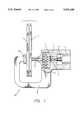
- FIG. 1is diagrammatic view of one embodiment of a device of this invention.
- FIGS. 2 through 5are diagrammatic views of projectiles of this invention.
- FIG. 6is a diagrammatic view of two pieces joined by a projectile.
- FIG. 1two pieces of material to be joined such as aluminum or aluminum alloy (1) are held in a vice-like device which is the joining mechanism (100) herein.
- joining mechanism (100)On one side of joining mechanism (100) is an impacter (2) and at the opposing side of joining mechanism (100) at the same level as impacter (2) is stopping mechanism (8).
- Extending parallel to impacter (2) and the pieces (1) being held by joining mechanism (100)is a projectile container (7) which joins u-shaped arm (9) that extends below pieces (1).
- U-shaped arm (9)connects at an end opposite its connection to projectile container (7), to stopping mechanism (8).
- one side of projectile container (7)connects to impacter (2).
- the opposing side of projectile container (1)connects to a barrel (5) which acts in part to hold pieces (1) against stopping mechanism (8).
- Impacter (2)is comprised of a hammer (3) movably situated with respect to a locking mechanism (4) and spring means (10). This is a very rough depiction of an impacter device and any impacter device is suitable. The device must merely cause a hammer (3) to move forcefully against a projectile held in projectile container (7) to propel that projectile into barrel (5) and into pieces (1).
- Impacters of this natureare: electro-magnetic, gas cylinder, hydraulic, mechanical such as mechanical off-center drive-shaft with a clutch, and explosive-triggering devices.
- the locking mechanism (4)may well act as a clutch unit to compress a mechanical lever that would lock hammer (3) after each impact.
- Projectile container (7)preferably includes a loading mechanism such as a magazine so that more than one projectile can be housed therein.
- the projectilescould simply drop from a holder into the container (7) or a chain driven loader held within container (7) is possible for holding projectiles and delivering them to a position for impact by the hammer (3).
- hammer (3) and barrel (5)be in alignment with each other and with the longitudinal axis of the projectile. It is also preferred that the barrel (5) be situated perpendicularly to the pieces (1) or at least be located in some means such that the projectile is delivered perpendicularly against pieces (1).
- FIGS. 2 through 5Some sample projectiles are seen in FIGS. 2 through 5. They are shown with cylindrical bodies (20) and tips (22) and are longer than they are wide thereby having a clear longitudinal axis along such length. In FIGS. 2 through 5, the tips (22) are symmetrically formed and generally rounded or pointed. It is intended that the tipb 54742366.001 impact first the pieces (1) to be joined. In the FIGS. 4 and 5, bodies (22) exhibit a concave groove or dent (24) therearound. As noted earlier herein, the projectiles are generally preferred to be made of the same material as the materials to be joined, or pieces (1). The configuration shown in the last two figures wherein grooves (24) are shown would likely be used when higher than usual friction is expected at impact causing excess material to melt upon contact of tip (22) of the with pieces (1).
- the impact strength, size of projectile, and length of barrel (5)are all dependent upon the material pieces (1) to be joined and, of course, the projectile material. This may be readily calculated when it is understood that the projectile is to penetrate pieces (1) to be joined and the mutual at least surface molten state of projectile and pieces (1) in the area surrounding the projectile is desired.
- the device of FIG. 1has adjustment means not shown for moving stopping mechanism (8) toward and away from barrel (5) to adjust to the width of pieces (1) to be held. It is also possible that barrel (5) could be adjustable in length or detachable to place different lengths of barrels (5) therein. Additionally, the inventor contemplates the use of a plurality of barrels (5) and impactors in one mechanism or even a mechanism to rotate pieces (1) between barrel (5) and stopping mechanism (8) so that a plurality of points of joinder are available.
- U-shaped arm (9)is somewhat flexible to absorb the shock of the impact of the projectile against the face of stopping mechanism (8).
- the face of stopping mechanism (8) which is impacted by tip (22)is of tool steel and preferably but not necessarily, the face of stopping mechanism (8) is flat.
- the surface hardening of the face of tool steel of 58-62 Rcwas sufficient. It is understood that the face of the stopping mechanism (8) must be constructed to arrest the motion of the projectile as it begins to penetrate completely through pieces (1).
- hammer (3) usedwas made from stainless steel 316 or Tool Steel. Needless to say, the portion of the hammer (3) which abuts the end of the projectile to project it into barrel (5) is of a size that is proportional to the size of the projectile to facilitate obtaining the desired speed of the projectile as it enters the barrel (5). In these tests, the barrel (5) was made of stainless steel 316 or high tempered steel.
- FIG. 6shows pieces (1) joined by a projectile.
- the flattened tip (22) and opposing body (20) endresults from the impact of the projectile with pieces (1) and in the case of tip (22) its abutment against stopping mechanism (8)
- the methodinvolves shooting a projectile of the same material as that material to be joined at the material to be joined and shooting it preferably perpendicular to that material.
- the speed at which the projectile is shottaking into account its own mass will cause the projectile to impact and penetrate the pieces of material to be joined. In doing so, the friction between the projectile and the material to be joined will result in micro melting of the material surrounding the projectile as well as the projectile and thereby the welding of the two base materials.
- the weld created in this fashionwill not exhibit perceivable crating or cracking in the substructure of the joint point.
- the impactermay be of any known construction such as explosive, mechanical, hydraulic, gas-driven, or electro-magnetic.
- the projectileis to be released in place for impact by the impacter such that interlayer stresses in the projectile are minimized.
- the projectileis preferably of the same material as the materials to be joined or welded.
- a loading mechanismfor use with the impacter.
- Such mechanismmay include a magazine such as used in firearms. Passage of the projectile through the pieces to be joined is stopped by a stopping mechanism which may be a single or multiple unit. It is only necessary that the tip of the projectile and its opposite end are ultimately flattened after impact and joining the pieces to be joined. These flattened ends create additional joining forces to hold the pieces that are joined together.
Landscapes
- Engineering & Computer Science (AREA)
- Mechanical Engineering (AREA)
- Pressure Welding/Diffusion-Bonding (AREA)
Abstract
Description
Claims (12)
Priority Applications (3)
| Application Number | Priority Date | Filing Date | Title |
|---|---|---|---|
| US08/255,274US5474226A (en) | 1994-06-08 | 1994-06-08 | Projectile welding |
| PCT/US1995/007265WO1995033593A2 (en) | 1994-06-08 | 1995-06-07 | Projectile welding |
| AU28199/95AAU2819995A (en) | 1994-06-08 | 1995-06-07 | Projectile welding |
Applications Claiming Priority (1)
| Application Number | Priority Date | Filing Date | Title |
|---|---|---|---|
| US08/255,274US5474226A (en) | 1994-06-08 | 1994-06-08 | Projectile welding |
Publications (1)
| Publication Number | Publication Date |
|---|---|
| US5474226Atrue US5474226A (en) | 1995-12-12 |
Family
ID=22967599
Family Applications (1)
| Application Number | Title | Priority Date | Filing Date |
|---|---|---|---|
| US08/255,274Expired - Fee RelatedUS5474226A (en) | 1994-06-08 | 1994-06-08 | Projectile welding |
Country Status (3)
| Country | Link |
|---|---|
| US (1) | US5474226A (en) |
| AU (1) | AU2819995A (en) |
| WO (1) | WO1995033593A2 (en) |
Cited By (39)
| Publication number | Priority date | Publication date | Assignee | Title |
|---|---|---|---|---|
| US5875953A (en)* | 1995-06-23 | 1999-03-02 | Toyota Jidosha Kabushiki Kaisha | Method and apparatus for effecting interference fit of two parts by accelerating the part or parts |
| US20030057262A1 (en)* | 2000-01-26 | 2003-03-27 | Klampfl Heinz Karl | Method for connecting two components by means of friction welding and a machine element produced according to said method |
| US6560846B1 (en) | 1996-12-20 | 2003-05-13 | Toyota Jidosha Kabushiki Kaisha | Method and apparatus for effecting interference fit of two parts by accelerating one of the parts |
| US20040069832A1 (en)* | 2002-10-11 | 2004-04-15 | John Banker | Kinetic energy welding process |
| US20050211867A1 (en)* | 2004-03-24 | 2005-09-29 | Margeson Christopher S | Acceleration clamp assist |
| US20060254039A1 (en)* | 2001-09-28 | 2006-11-16 | The Ohio State University | High velocity forming of local features using a projectile |
| US20090050676A1 (en)* | 2005-03-31 | 2009-02-26 | Renault S.A.S | Tool and method for assembling metal parts by impacting with the aid of magnetic force using two electromagnetic coils movable with respect to each other |
| US7658196B2 (en) | 2005-02-24 | 2010-02-09 | Ethicon Endo-Surgery, Inc. | System and method for determining implanted device orientation |
| US7775966B2 (en) | 2005-02-24 | 2010-08-17 | Ethicon Endo-Surgery, Inc. | Non-invasive pressure measurement in a fluid adjustable restrictive device |
| US7775215B2 (en) | 2005-02-24 | 2010-08-17 | Ethicon Endo-Surgery, Inc. | System and method for determining implanted device positioning and obtaining pressure data |
| US7844342B2 (en) | 2008-02-07 | 2010-11-30 | Ethicon Endo-Surgery, Inc. | Powering implantable restriction systems using light |
| US7927270B2 (en) | 2005-02-24 | 2011-04-19 | Ethicon Endo-Surgery, Inc. | External mechanical pressure sensor for gastric band pressure measurements |
| US8016744B2 (en) | 2005-02-24 | 2011-09-13 | Ethicon Endo-Surgery, Inc. | External pressure-based gastric band adjustment system and method |
| US8016745B2 (en) | 2005-02-24 | 2011-09-13 | Ethicon Endo-Surgery, Inc. | Monitoring of a food intake restriction device |
| US8034065B2 (en) | 2008-02-26 | 2011-10-11 | Ethicon Endo-Surgery, Inc. | Controlling pressure in adjustable restriction devices |
| US8057492B2 (en) | 2008-02-12 | 2011-11-15 | Ethicon Endo-Surgery, Inc. | Automatically adjusting band system with MEMS pump |
| US8066629B2 (en) | 2005-02-24 | 2011-11-29 | Ethicon Endo-Surgery, Inc. | Apparatus for adjustment and sensing of gastric band pressure |
| US8100870B2 (en) | 2007-12-14 | 2012-01-24 | Ethicon Endo-Surgery, Inc. | Adjustable height gastric restriction devices and methods |
| US8114345B2 (en) | 2008-02-08 | 2012-02-14 | Ethicon Endo-Surgery, Inc. | System and method of sterilizing an implantable medical device |
| US8142452B2 (en) | 2007-12-27 | 2012-03-27 | Ethicon Endo-Surgery, Inc. | Controlling pressure in adjustable restriction devices |
| US8152710B2 (en) | 2006-04-06 | 2012-04-10 | Ethicon Endo-Surgery, Inc. | Physiological parameter analysis for an implantable restriction device and a data logger |
| US8187163B2 (en) | 2007-12-10 | 2012-05-29 | Ethicon Endo-Surgery, Inc. | Methods for implanting a gastric restriction device |
| US8187162B2 (en) | 2008-03-06 | 2012-05-29 | Ethicon Endo-Surgery, Inc. | Reorientation port |
| US8192350B2 (en) | 2008-01-28 | 2012-06-05 | Ethicon Endo-Surgery, Inc. | Methods and devices for measuring impedance in a gastric restriction system |
| US8221439B2 (en) | 2008-02-07 | 2012-07-17 | Ethicon Endo-Surgery, Inc. | Powering implantable restriction systems using kinetic motion |
| US8233995B2 (en) | 2008-03-06 | 2012-07-31 | Ethicon Endo-Surgery, Inc. | System and method of aligning an implantable antenna |
| US8337389B2 (en) | 2008-01-28 | 2012-12-25 | Ethicon Endo-Surgery, Inc. | Methods and devices for diagnosing performance of a gastric restriction system |
| US8377079B2 (en) | 2007-12-27 | 2013-02-19 | Ethicon Endo-Surgery, Inc. | Constant force mechanisms for regulating restriction devices |
| US8591395B2 (en) | 2008-01-28 | 2013-11-26 | Ethicon Endo-Surgery, Inc. | Gastric restriction device data handling devices and methods |
| US8591532B2 (en) | 2008-02-12 | 2013-11-26 | Ethicon Endo-Sugery, Inc. | Automatically adjusting band system |
| US8679399B2 (en) | 2011-06-13 | 2014-03-25 | Eric Bleicken | Apparatus for metal cutting and welding |
| US8870742B2 (en) | 2006-04-06 | 2014-10-28 | Ethicon Endo-Surgery, Inc. | GUI for an implantable restriction device and a data logger |
| US9175938B2 (en) | 2011-06-13 | 2015-11-03 | Darrel Barnette | Rotating and oscillating breaching device with reactive material |
| US9365463B1 (en) | 2011-06-13 | 2016-06-14 | Darrel Barnette | Rotating and oscillating breaching device with reactive material |
| US20180272464A1 (en)* | 2016-02-17 | 2018-09-27 | Siemens Energy, Inc. | Discharge actuated solid state additive manufacturing |
| IT202000028652A1 (en)* | 2020-11-26 | 2022-05-26 | Manz Italy Srl | METHOD AND APPARATUS FOR ASSEMBLING AN ELECTRIC ENERGY STORAGE DEVICE |
| US11649073B2 (en) | 2009-02-24 | 2023-05-16 | Blue Origin, Llc | Control surfaces for use with high speed vehicles, and associated systems and methods |
| US11873122B2 (en) | 2021-03-02 | 2024-01-16 | Blue Origin, Llc | Systems and methods for bonding objects using energetic welding |
| US11884427B2 (en) | 2021-07-07 | 2024-01-30 | Blue Origin Llc | Stud-propelling mechanisms for securing a launch vehicle to a landing platform, and associated systems and methods |
Citations (19)
| Publication number | Priority date | Publication date | Assignee | Title |
|---|---|---|---|---|
| US2563107A (en)* | 1949-11-30 | 1951-08-07 | Herman J Fanger | Method of forming a welded connection and means therefor |
| US2957237A (en)* | 1955-01-13 | 1960-10-25 | Welding Research Inc | Method of making a brazed riveted connection |
| US3544761A (en)* | 1965-11-29 | 1970-12-01 | Mitron Research & Dev Corp | Process of welding aluminum |
| US3609286A (en)* | 1967-11-17 | 1971-09-28 | Cegedur Gp | Process for treatment of aluminum and alloys of aluminum for resistance welding |
| US3958743A (en)* | 1974-07-22 | 1976-05-25 | Japan Gasoline Co., Ltd. | Welding process for aluminum or chrome diffusion-coated steel |
| US3988146A (en)* | 1972-11-17 | 1976-10-26 | Aluminum Company Of America | Process for producing large particle size aluminum pigments by working and welding smaller particles |
| US4019018A (en)* | 1974-09-30 | 1977-04-19 | Kobe Steel Ltd. | Process for narrow gap welding of aluminum alloy thick plates |
| US4037078A (en)* | 1974-05-23 | 1977-07-19 | Kobe Steel Ltd. | Process for welding aluminum and aluminum alloys in horizontal welding position |
| US4368371A (en)* | 1979-09-08 | 1983-01-11 | Messer Griesheim | Process for the submerged-arc welding of light metals such as aluminum and aluminum alloys |
| US4591687A (en)* | 1982-03-04 | 1986-05-27 | Paul Opprecht | Electrical resistance-pressure welding process for welding parts of workpieces made of aluminum materials and an apparatus and electrode therefor |
| US4674672A (en)* | 1986-03-17 | 1987-06-23 | Alcotec Wire Co. | Process for welding aluminum articles |
| US4760240A (en)* | 1983-02-24 | 1988-07-26 | Fujitsu Limited | Process for laser welding of aluminum based elements |
| US5015816A (en)* | 1988-10-20 | 1991-05-14 | Cmw, Inc. | Resistance welding electrode and process |
| US5024371A (en)* | 1989-12-26 | 1991-06-18 | Unde Madhav A | Welding process |
| US5082160A (en)* | 1990-01-10 | 1992-01-21 | Gas Research Institute | Apparatus and process for ultrasonic seam welding stainless steel foils |
| US5104456A (en)* | 1990-02-15 | 1992-04-14 | Colorado School Of Mines | Process for optimizing titanium and zirconium additions to aluminum welding consumables |
| US5126528A (en)* | 1988-10-20 | 1992-06-30 | Cmw, Inc. | Resistance welding electrode having an angled nose and process of fabrication thereof |
| US5171378A (en)* | 1989-09-13 | 1992-12-15 | Erico International Corporation | Aluminum welding process and mixture of reactants for use in such process |
| US5244645A (en)* | 1991-10-01 | 1993-09-14 | Shell Oil Company | Process for removing NH3 from a liquid stream |
Family Cites Families (3)
| Publication number | Priority date | Publication date | Assignee | Title |
|---|---|---|---|---|
| US3951326A (en)* | 1974-08-30 | 1976-04-20 | Avesta Jernverks Aktiebolag | Apparatus for explosion welding of a covering plate to a bed plate of another metal |
| US4504714A (en)* | 1981-11-02 | 1985-03-12 | Jack Katzenstein | System and method for impact welding by magnetic propulsion |
| DE3530872C1 (en)* | 1985-08-29 | 1987-03-05 | Heinrich Dr-Ing Hampel | Process for explosive plating of metal sheets |
- 1994
- 1994-06-08USUS08/255,274patent/US5474226A/ennot_activeExpired - Fee Related
- 1995
- 1995-06-07AUAU28199/95Apatent/AU2819995A/ennot_activeAbandoned
- 1995-06-07WOPCT/US1995/007265patent/WO1995033593A2/enactiveApplication Filing
Patent Citations (19)
| Publication number | Priority date | Publication date | Assignee | Title |
|---|---|---|---|---|
| US2563107A (en)* | 1949-11-30 | 1951-08-07 | Herman J Fanger | Method of forming a welded connection and means therefor |
| US2957237A (en)* | 1955-01-13 | 1960-10-25 | Welding Research Inc | Method of making a brazed riveted connection |
| US3544761A (en)* | 1965-11-29 | 1970-12-01 | Mitron Research & Dev Corp | Process of welding aluminum |
| US3609286A (en)* | 1967-11-17 | 1971-09-28 | Cegedur Gp | Process for treatment of aluminum and alloys of aluminum for resistance welding |
| US3988146A (en)* | 1972-11-17 | 1976-10-26 | Aluminum Company Of America | Process for producing large particle size aluminum pigments by working and welding smaller particles |
| US4037078A (en)* | 1974-05-23 | 1977-07-19 | Kobe Steel Ltd. | Process for welding aluminum and aluminum alloys in horizontal welding position |
| US3958743A (en)* | 1974-07-22 | 1976-05-25 | Japan Gasoline Co., Ltd. | Welding process for aluminum or chrome diffusion-coated steel |
| US4019018A (en)* | 1974-09-30 | 1977-04-19 | Kobe Steel Ltd. | Process for narrow gap welding of aluminum alloy thick plates |
| US4368371A (en)* | 1979-09-08 | 1983-01-11 | Messer Griesheim | Process for the submerged-arc welding of light metals such as aluminum and aluminum alloys |
| US4591687A (en)* | 1982-03-04 | 1986-05-27 | Paul Opprecht | Electrical resistance-pressure welding process for welding parts of workpieces made of aluminum materials and an apparatus and electrode therefor |
| US4760240A (en)* | 1983-02-24 | 1988-07-26 | Fujitsu Limited | Process for laser welding of aluminum based elements |
| US4674672A (en)* | 1986-03-17 | 1987-06-23 | Alcotec Wire Co. | Process for welding aluminum articles |
| US5015816A (en)* | 1988-10-20 | 1991-05-14 | Cmw, Inc. | Resistance welding electrode and process |
| US5126528A (en)* | 1988-10-20 | 1992-06-30 | Cmw, Inc. | Resistance welding electrode having an angled nose and process of fabrication thereof |
| US5171378A (en)* | 1989-09-13 | 1992-12-15 | Erico International Corporation | Aluminum welding process and mixture of reactants for use in such process |
| US5024371A (en)* | 1989-12-26 | 1991-06-18 | Unde Madhav A | Welding process |
| US5082160A (en)* | 1990-01-10 | 1992-01-21 | Gas Research Institute | Apparatus and process for ultrasonic seam welding stainless steel foils |
| US5104456A (en)* | 1990-02-15 | 1992-04-14 | Colorado School Of Mines | Process for optimizing titanium and zirconium additions to aluminum welding consumables |
| US5244645A (en)* | 1991-10-01 | 1993-09-14 | Shell Oil Company | Process for removing NH3 from a liquid stream |
Cited By (45)
| Publication number | Priority date | Publication date | Assignee | Title |
|---|---|---|---|---|
| US5875953A (en)* | 1995-06-23 | 1999-03-02 | Toyota Jidosha Kabushiki Kaisha | Method and apparatus for effecting interference fit of two parts by accelerating the part or parts |
| US6560846B1 (en) | 1996-12-20 | 2003-05-13 | Toyota Jidosha Kabushiki Kaisha | Method and apparatus for effecting interference fit of two parts by accelerating one of the parts |
| US20030057262A1 (en)* | 2000-01-26 | 2003-03-27 | Klampfl Heinz Karl | Method for connecting two components by means of friction welding and a machine element produced according to said method |
| US20060254039A1 (en)* | 2001-09-28 | 2006-11-16 | The Ohio State University | High velocity forming of local features using a projectile |
| US20040069832A1 (en)* | 2002-10-11 | 2004-04-15 | John Banker | Kinetic energy welding process |
| WO2004033142A1 (en)* | 2002-10-11 | 2004-04-22 | Dynamic Materials Corporation | Kinetic energy welding process |
| US6772934B2 (en)* | 2002-10-11 | 2004-08-10 | Dynamic Materials Corporation | Kinetic energy welding process |
| EP1565287A4 (en)* | 2002-10-11 | 2008-08-06 | Dynamic Materials Corp | Kinetic energy welding process |
| US20050211867A1 (en)* | 2004-03-24 | 2005-09-29 | Margeson Christopher S | Acceleration clamp assist |
| US7296777B2 (en)* | 2004-03-24 | 2007-11-20 | Nikon Corporation | Acceleration clamp assist |
| US7927270B2 (en) | 2005-02-24 | 2011-04-19 | Ethicon Endo-Surgery, Inc. | External mechanical pressure sensor for gastric band pressure measurements |
| US7658196B2 (en) | 2005-02-24 | 2010-02-09 | Ethicon Endo-Surgery, Inc. | System and method for determining implanted device orientation |
| US7775966B2 (en) | 2005-02-24 | 2010-08-17 | Ethicon Endo-Surgery, Inc. | Non-invasive pressure measurement in a fluid adjustable restrictive device |
| US7775215B2 (en) | 2005-02-24 | 2010-08-17 | Ethicon Endo-Surgery, Inc. | System and method for determining implanted device positioning and obtaining pressure data |
| US8016744B2 (en) | 2005-02-24 | 2011-09-13 | Ethicon Endo-Surgery, Inc. | External pressure-based gastric band adjustment system and method |
| US8016745B2 (en) | 2005-02-24 | 2011-09-13 | Ethicon Endo-Surgery, Inc. | Monitoring of a food intake restriction device |
| US8066629B2 (en) | 2005-02-24 | 2011-11-29 | Ethicon Endo-Surgery, Inc. | Apparatus for adjustment and sensing of gastric band pressure |
| US20090050676A1 (en)* | 2005-03-31 | 2009-02-26 | Renault S.A.S | Tool and method for assembling metal parts by impacting with the aid of magnetic force using two electromagnetic coils movable with respect to each other |
| US7959057B2 (en)* | 2005-03-31 | 2011-06-14 | Renault S.A.S. | Tool and method for assembling metal parts by impacting with the aid of a magnetic force using two electromagnetic coils movable with respect to each other |
| US8870742B2 (en) | 2006-04-06 | 2014-10-28 | Ethicon Endo-Surgery, Inc. | GUI for an implantable restriction device and a data logger |
| US8152710B2 (en) | 2006-04-06 | 2012-04-10 | Ethicon Endo-Surgery, Inc. | Physiological parameter analysis for an implantable restriction device and a data logger |
| US8187163B2 (en) | 2007-12-10 | 2012-05-29 | Ethicon Endo-Surgery, Inc. | Methods for implanting a gastric restriction device |
| US8100870B2 (en) | 2007-12-14 | 2012-01-24 | Ethicon Endo-Surgery, Inc. | Adjustable height gastric restriction devices and methods |
| US8377079B2 (en) | 2007-12-27 | 2013-02-19 | Ethicon Endo-Surgery, Inc. | Constant force mechanisms for regulating restriction devices |
| US8142452B2 (en) | 2007-12-27 | 2012-03-27 | Ethicon Endo-Surgery, Inc. | Controlling pressure in adjustable restriction devices |
| US8591395B2 (en) | 2008-01-28 | 2013-11-26 | Ethicon Endo-Surgery, Inc. | Gastric restriction device data handling devices and methods |
| US8192350B2 (en) | 2008-01-28 | 2012-06-05 | Ethicon Endo-Surgery, Inc. | Methods and devices for measuring impedance in a gastric restriction system |
| US8337389B2 (en) | 2008-01-28 | 2012-12-25 | Ethicon Endo-Surgery, Inc. | Methods and devices for diagnosing performance of a gastric restriction system |
| US7844342B2 (en) | 2008-02-07 | 2010-11-30 | Ethicon Endo-Surgery, Inc. | Powering implantable restriction systems using light |
| US8221439B2 (en) | 2008-02-07 | 2012-07-17 | Ethicon Endo-Surgery, Inc. | Powering implantable restriction systems using kinetic motion |
| US8114345B2 (en) | 2008-02-08 | 2012-02-14 | Ethicon Endo-Surgery, Inc. | System and method of sterilizing an implantable medical device |
| US8591532B2 (en) | 2008-02-12 | 2013-11-26 | Ethicon Endo-Sugery, Inc. | Automatically adjusting band system |
| US8057492B2 (en) | 2008-02-12 | 2011-11-15 | Ethicon Endo-Surgery, Inc. | Automatically adjusting band system with MEMS pump |
| US8034065B2 (en) | 2008-02-26 | 2011-10-11 | Ethicon Endo-Surgery, Inc. | Controlling pressure in adjustable restriction devices |
| US8233995B2 (en) | 2008-03-06 | 2012-07-31 | Ethicon Endo-Surgery, Inc. | System and method of aligning an implantable antenna |
| US8187162B2 (en) | 2008-03-06 | 2012-05-29 | Ethicon Endo-Surgery, Inc. | Reorientation port |
| US11649073B2 (en) | 2009-02-24 | 2023-05-16 | Blue Origin, Llc | Control surfaces for use with high speed vehicles, and associated systems and methods |
| US8679399B2 (en) | 2011-06-13 | 2014-03-25 | Eric Bleicken | Apparatus for metal cutting and welding |
| US9175938B2 (en) | 2011-06-13 | 2015-11-03 | Darrel Barnette | Rotating and oscillating breaching device with reactive material |
| US9365463B1 (en) | 2011-06-13 | 2016-06-14 | Darrel Barnette | Rotating and oscillating breaching device with reactive material |
| US20180272464A1 (en)* | 2016-02-17 | 2018-09-27 | Siemens Energy, Inc. | Discharge actuated solid state additive manufacturing |
| US10906128B2 (en)* | 2016-02-17 | 2021-02-02 | Siemens Energy, Inc. | Discharge actuated solid state additive manufacturing |
| IT202000028652A1 (en)* | 2020-11-26 | 2022-05-26 | Manz Italy Srl | METHOD AND APPARATUS FOR ASSEMBLING AN ELECTRIC ENERGY STORAGE DEVICE |
| US11873122B2 (en) | 2021-03-02 | 2024-01-16 | Blue Origin, Llc | Systems and methods for bonding objects using energetic welding |
| US11884427B2 (en) | 2021-07-07 | 2024-01-30 | Blue Origin Llc | Stud-propelling mechanisms for securing a launch vehicle to a landing platform, and associated systems and methods |
Also Published As
| Publication number | Publication date |
|---|---|
| WO1995033593A2 (en) | 1995-12-14 |
| WO1995033593A3 (en) | 1995-12-28 |
| AU2819995A (en) | 1996-01-04 |
Similar Documents
| Publication | Publication Date | Title |
|---|---|---|
| US5474226A (en) | Projectile welding | |
| Crossland et al. | Explosive welding | |
| US20120103949A1 (en) | Laser-induced metallurgical bonding driven without contact | |
| Bahrani et al. | The mechanics of wave formation in explosive welding | |
| US8087143B2 (en) | Method for producing armor through metallic encapsulation of a ceramic core | |
| AU611500B2 (en) | Drilling dowel | |
| US3434197A (en) | Explosive welding | |
| US3737975A (en) | Arrangement for explosively formed connections and method of making such connections | |
| US20090261146A1 (en) | Donor material technology for friction stir welding | |
| US10906128B2 (en) | Discharge actuated solid state additive manufacturing | |
| US20170184379A1 (en) | Containers for explosives and positioning apparatuses for the same | |
| JP3781840B2 (en) | Method of joining aluminum material and dissimilar metal material | |
| US20030012619A1 (en) | Method and apparatus for fastening steel framing with a spin weld pin | |
| US7887092B1 (en) | Vehicle assisted harpoon breaching tool | |
| Crossland et al. | Fundamentals, of explosive welding | |
| US6772934B2 (en) | Kinetic energy welding process | |
| US6183378B1 (en) | Golf clubs with brazed ceramic and cermet compounds | |
| EP1898174B1 (en) | Reactive ballistic protection plate | |
| Vigueras et al. | Explosive and impact welding: technical review | |
| TW200408507A (en) | Explosively actuated tools | |
| CN101559516B (en) | Explosive welding device for bulk amorphous alloy and common metal | |
| EP1045222B1 (en) | Shrapnel type projectile | |
| US4740036A (en) | Splitting apparatus and method | |
| Turner et al. | Spot impact welding of sheet aluminum | |
| Rinehart | Historical perspective: metallurgical effects of high strain-rate deformation and fabrication |
Legal Events
| Date | Code | Title | Description |
|---|---|---|---|
| AS | Assignment | Owner name:ORBIT TECHNOLOGIES, INC., CALIFORNIA Free format text:ASSIGNMENT OF ASSIGNORS INTEREST;ASSIGNOR:JOSEPH, ADRIAN A.;REEL/FRAME:007074/0100 Effective date:19940706 | |
| AS | Assignment | Owner name:JEFFER, MANGELS, BUTLER & MARMARO, LLP, CALIFORNIA Free format text:JUDGMENT LIEN;ASSIGNOR:ORBIT TECHNOLOGIES, INC.;REEL/FRAME:008811/0780 Effective date:19971107 | |
| REMI | Maintenance fee reminder mailed | ||
| LAPS | Lapse for failure to pay maintenance fees | ||
| FP | Lapsed due to failure to pay maintenance fee | Effective date:19991212 | |
| AS | Assignment | Owner name:AJW PARTNERS, LLC, NEW YORK Free format text:SECURITY INTEREST;ASSIGNOR:TECHNOLOGY VISIONS GROUP, INC.;REEL/FRAME:011390/0371 Effective date:20001227 Owner name:NEW MILLENIUM CAPITAL PARTNERS II, LLC, NEW YORK Free format text:SECURITY INTEREST;ASSIGNOR:TECHNOLOGY VISIONS GROUP, INC.;REEL/FRAME:011390/0371 Effective date:20001227 | |
| AS | Assignment | Owner name:TECHNOLOGY VISIONS GROUP, INC., CALIFORNIA Free format text:TERMINATION OF SECURITY INTEREST;ASSIGNORS:AJW PARTNERS, LLC;NEW MILLENIUM CAPITAL PARTNERS, LLC;REEL/FRAME:013248/0323 Effective date:20020828 | |
| STCH | Information on status: patent discontinuation | Free format text:PATENT EXPIRED DUE TO NONPAYMENT OF MAINTENANCE FEES UNDER 37 CFR 1.362 |