US5473111A - Shielded enclosure for housing electronic components and manufacturing method thereof - Google Patents
Shielded enclosure for housing electronic components and manufacturing method thereofDownload PDFInfo
- Publication number
- US5473111A US5473111AUS08/120,468US12046893AUS5473111AUS 5473111 AUS5473111 AUS 5473111AUS 12046893 AUS12046893 AUS 12046893AUS 5473111 AUS5473111 AUS 5473111A
- Authority
- US
- United States
- Prior art keywords
- enclosure
- shield member
- electromagnetic interference
- die
- interference shield
- Prior art date
- Legal status (The legal status is an assumption and is not a legal conclusion. Google has not performed a legal analysis and makes no representation as to the accuracy of the status listed.)
- Expired - Fee Related
Links
Images

Classifications
- H—ELECTRICITY
- H05—ELECTRIC TECHNIQUES NOT OTHERWISE PROVIDED FOR
- H05K—PRINTED CIRCUITS; CASINGS OR CONSTRUCTIONAL DETAILS OF ELECTRIC APPARATUS; MANUFACTURE OF ASSEMBLAGES OF ELECTRICAL COMPONENTS
- H05K9/00—Screening of apparatus or components against electric or magnetic fields
- H05K9/0073—Shielding materials
- H05K9/0081—Electromagnetic shielding materials, e.g. EMI, RFI shielding
- H05K9/0084—Electromagnetic shielding materials, e.g. EMI, RFI shielding comprising a single continuous metallic layer on an electrically insulating supporting structure, e.g. metal foil, film, plating coating, electro-deposition, vapour-deposition
- B—PERFORMING OPERATIONS; TRANSPORTING
- B29—WORKING OF PLASTICS; WORKING OF SUBSTANCES IN A PLASTIC STATE IN GENERAL
- B29C—SHAPING OR JOINING OF PLASTICS; SHAPING OF MATERIAL IN A PLASTIC STATE, NOT OTHERWISE PROVIDED FOR; AFTER-TREATMENT OF THE SHAPED PRODUCTS, e.g. REPAIRING
- B29C45/00—Injection moulding, i.e. forcing the required volume of moulding material through a nozzle into a closed mould; Apparatus therefor
- B29C45/14—Injection moulding, i.e. forcing the required volume of moulding material through a nozzle into a closed mould; Apparatus therefor incorporating preformed parts or layers, e.g. injection moulding around inserts or for coating articles
- B29C45/1418—Injection moulding, i.e. forcing the required volume of moulding material through a nozzle into a closed mould; Apparatus therefor incorporating preformed parts or layers, e.g. injection moulding around inserts or for coating articles the inserts being deformed or preformed, e.g. by the injection pressure
- B—PERFORMING OPERATIONS; TRANSPORTING
- B29—WORKING OF PLASTICS; WORKING OF SUBSTANCES IN A PLASTIC STATE IN GENERAL
- B29C—SHAPING OR JOINING OF PLASTICS; SHAPING OF MATERIAL IN A PLASTIC STATE, NOT OTHERWISE PROVIDED FOR; AFTER-TREATMENT OF THE SHAPED PRODUCTS, e.g. REPAIRING
- B29C45/00—Injection moulding, i.e. forcing the required volume of moulding material through a nozzle into a closed mould; Apparatus therefor
- B29C45/14—Injection moulding, i.e. forcing the required volume of moulding material through a nozzle into a closed mould; Apparatus therefor incorporating preformed parts or layers, e.g. injection moulding around inserts or for coating articles
- B29C45/14778—Injection moulding, i.e. forcing the required volume of moulding material through a nozzle into a closed mould; Apparatus therefor incorporating preformed parts or layers, e.g. injection moulding around inserts or for coating articles the article consisting of a material with particular properties, e.g. porous, brittle
- B29C45/14795—Porous or permeable material, e.g. foam
- B—PERFORMING OPERATIONS; TRANSPORTING
- B29—WORKING OF PLASTICS; WORKING OF SUBSTANCES IN A PLASTIC STATE IN GENERAL
- B29C—SHAPING OR JOINING OF PLASTICS; SHAPING OF MATERIAL IN A PLASTIC STATE, NOT OTHERWISE PROVIDED FOR; AFTER-TREATMENT OF THE SHAPED PRODUCTS, e.g. REPAIRING
- B29C70/00—Shaping composites, i.e. plastics material comprising reinforcements, fillers or preformed parts, e.g. inserts
- B29C70/88—Shaping composites, i.e. plastics material comprising reinforcements, fillers or preformed parts, e.g. inserts characterised primarily by possessing specific properties, e.g. electrically conductive or locally reinforced
- B29C70/882—Shaping composites, i.e. plastics material comprising reinforcements, fillers or preformed parts, e.g. inserts characterised primarily by possessing specific properties, e.g. electrically conductive or locally reinforced partly or totally electrically conductive, e.g. for EMI shielding
- B29C70/885—Shaping composites, i.e. plastics material comprising reinforcements, fillers or preformed parts, e.g. inserts characterised primarily by possessing specific properties, e.g. electrically conductive or locally reinforced partly or totally electrically conductive, e.g. for EMI shielding with incorporated metallic wires, nets, films or plates
- H—ELECTRICITY
- H05—ELECTRIC TECHNIQUES NOT OTHERWISE PROVIDED FOR
- H05K—PRINTED CIRCUITS; CASINGS OR CONSTRUCTIONAL DETAILS OF ELECTRIC APPARATUS; MANUFACTURE OF ASSEMBLAGES OF ELECTRICAL COMPONENTS
- H05K9/00—Screening of apparatus or components against electric or magnetic fields
- H05K9/0007—Casings
- H05K9/0045—Casings being rigid plastic containers having a coating of shielding material
- H—ELECTRICITY
- H05—ELECTRIC TECHNIQUES NOT OTHERWISE PROVIDED FOR
- H05K—PRINTED CIRCUITS; CASINGS OR CONSTRUCTIONAL DETAILS OF ELECTRIC APPARATUS; MANUFACTURE OF ASSEMBLAGES OF ELECTRICAL COMPONENTS
- H05K9/00—Screening of apparatus or components against electric or magnetic fields
- H05K9/0007—Casings
- H05K9/0047—Casings being rigid plastic containers having conductive particles, fibres or mesh embedded therein
- B—PERFORMING OPERATIONS; TRANSPORTING
- B29—WORKING OF PLASTICS; WORKING OF SUBSTANCES IN A PLASTIC STATE IN GENERAL
- B29K—INDEXING SCHEME ASSOCIATED WITH SUBCLASSES B29B, B29C OR B29D, RELATING TO MOULDING MATERIALS OR TO MATERIALS FOR MOULDS, REINFORCEMENTS, FILLERS OR PREFORMED PARTS, e.g. INSERTS
- B29K2105/00—Condition, form or state of moulded material or of the material to be shaped
- B29K2105/06—Condition, form or state of moulded material or of the material to be shaped containing reinforcements, fillers or inserts
- B29K2105/20—Inserts
- B29K2105/206—Meshes, lattices or nets
- B—PERFORMING OPERATIONS; TRANSPORTING
- B29—WORKING OF PLASTICS; WORKING OF SUBSTANCES IN A PLASTIC STATE IN GENERAL
- B29K—INDEXING SCHEME ASSOCIATED WITH SUBCLASSES B29B, B29C OR B29D, RELATING TO MOULDING MATERIALS OR TO MATERIALS FOR MOULDS, REINFORCEMENTS, FILLERS OR PREFORMED PARTS, e.g. INSERTS
- B29K2705/00—Use of metals, their alloys or their compounds, for preformed parts, e.g. for inserts
- B—PERFORMING OPERATIONS; TRANSPORTING
- B29—WORKING OF PLASTICS; WORKING OF SUBSTANCES IN A PLASTIC STATE IN GENERAL
- B29K—INDEXING SCHEME ASSOCIATED WITH SUBCLASSES B29B, B29C OR B29D, RELATING TO MOULDING MATERIALS OR TO MATERIALS FOR MOULDS, REINFORCEMENTS, FILLERS OR PREFORMED PARTS, e.g. INSERTS
- B29K2995/00—Properties of moulding materials, reinforcements, fillers, preformed parts or moulds
- B29K2995/0003—Properties of moulding materials, reinforcements, fillers, preformed parts or moulds having particular electrical or magnetic properties, e.g. piezoelectric
- B29K2995/0011—Electromagnetic wave shielding material
- B—PERFORMING OPERATIONS; TRANSPORTING
- B29—WORKING OF PLASTICS; WORKING OF SUBSTANCES IN A PLASTIC STATE IN GENERAL
- B29L—INDEXING SCHEME ASSOCIATED WITH SUBCLASS B29C, RELATING TO PARTICULAR ARTICLES
- B29L2031/00—Other particular articles
- B29L2031/712—Containers; Packaging elements or accessories, Packages
- B29L2031/7162—Boxes, cartons, cases
- Y—GENERAL TAGGING OF NEW TECHNOLOGICAL DEVELOPMENTS; GENERAL TAGGING OF CROSS-SECTIONAL TECHNOLOGIES SPANNING OVER SEVERAL SECTIONS OF THE IPC; TECHNICAL SUBJECTS COVERED BY FORMER USPC CROSS-REFERENCE ART COLLECTIONS [XRACs] AND DIGESTS
- Y10—TECHNICAL SUBJECTS COVERED BY FORMER USPC
- Y10T—TECHNICAL SUBJECTS COVERED BY FORMER US CLASSIFICATION
- Y10T29/00—Metal working
- Y10T29/49—Method of mechanical manufacture
- Y10T29/4998—Combined manufacture including applying or shaping of fluent material
- Y10T29/49982—Coating
- Y10T29/49986—Subsequent to metal working
Definitions
- the present inventionrelates to an enclosure, consisting of a box or a cover for housing electronic parts or equipment to protect the electronic parts or equipment from electromagnetic interference (EMI), and to a method of manufacturing the enclosure.
- EMIelectromagnetic interference
- a variety of conventional techniquesare employed as the methods of EMI-shielding for plastic molded enclosures. Among these are the following: (1) a method wherein paint using a conductive material, e.g., silver or copper, as a filler, is applied to an enclosure after the molding of the enclosure, (2) a flame spraying method wherein the conductive material, e.g., silver or copper, is fused and sprayed to an enclosure by high-pressure air, (3) a vacuum metallizing method wherein metal of low boiling point (such as aluminum) is evaporated in a vacuum to form a thin film on enclosure surfaces, (4) a method wherein electroless plating of nickel, etc., is provided to an enclosure molded by high-adhesive resin, e.g., ABS resin, (5) a method wherein a molding material filled with a conductive filler, such as carbon or aluminum flakes, is used to mold an enclosure, and (6) a method wherein a composite material made by laminating a polyvinyl chloride
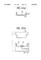
- FIG. 6(a)shows a housing for digital electronic equipment disclosed in Japanese Laid-Open Patent Publication SHO 61-22915, wherein the numeral 217' indicates resin and 215' represents a wire netting.
- FIG. 6(b)is a diagrammatic sectional view of dies and illustrates a molding state, wherein 211 denotes an upper die, 212 designates a lower die, 213 indicates a resin gate provided in the lower die 212, and 215 denotes an electromagnetic interference reflecting and interrupting wire netting.
- the wire netting 215is placed on the lower die 212 and supplied with fused resin 217 from the gate 213, the upper die 211 is subsequently closed, and the wire netting 215 is then pressed.
- the molding processis complete and the enclosure is removed.
- the nettingmust be preformed in a box shape so that corners can be properly shaped in the enclosure.
- the preforming of the netting into other shapesis required, depending on the final shape of the enclosure.
- FIG. 7(a)shows an electronic apparatus disclosed in Japanese Laid-Open Utility Model Publication SHO 63-201391, wherein 71 indicates a metal chassis containing electronic parts, electronic circuits, etc., and 73 denotes a cover.
- the metal chassis 71houses electronic circuit cards 72.
- the cover 73is made of a wire netting 74 and plastics which are formed integrally, the wire netting 74 is exposed in the periphery of the cover 73 so that when the cover 73 is fitted to the chassis 71, the wire netting 74 and chassis 71 are electrically conductive. It should be noted that a cover manufacturing method is not described in this publication.
- the conventional methods of molding an enclosure and subsequently forming a conductive film on an enclosure surface by any of conductive paint application, conductive material flame-spraying, vacuum metallizing and resin platingare high-priced and have the problem of film peeling. Also, the method of using a molding material filled with a conductive filler to mold an enclosure does not provide a uniform dispersion of the conductive filler inside a molded product and provides a poor shielding effect.
- the method disclosed in Japanese Laid-Open Patent Publication SHO 61-22915required the wire netting to be preformed, resulting in a larger number of processes and higher cost. Further, the method disclosed in Japanese Laid-Open Utility Model Publication SHO 63-201391 involves high costs because one part of the enclosure was made of metal.
- an object of the present inventionto overcome the disadvantages in the conventional art by providing an enclosure and an enclosure manufacturing method which allow a shield material to be molded integrally with resin without pre-forming, whereby the enclosure and its manufacturing method are low in price, high in workability, and have an electromagnetic interference shielding function.
- an electromagnetic interference shield memberis disposed inside the molded resin in order to protect the electronic parts or electronic equipment from electromagnetic interference and the electromagnetic interference shield member is exposed at the edges of the enclosure and provides a contact or other connection to ground, even where the wall of the enclosure is thin.
- the method of shaping and securing the electromagnetic interference shield member during closure of the dieis a further feature of the invention in that it eliminates the need for any pre-forming of the electromagnetic interference shield member.
- the air vent feature of the present inventionreleases high-temperature air from inside the enclosure to the outside while maintaining EMI protection.
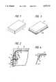
- FIG. 1is a perspective view of an enclosure consisting of a box and a cover for housing electronic parts or equipment as a preferred embodiment of the present invention.
- FIG. 2is a sectional view illustrating some portion of FIG. 1.
- FIG. 3is a perspective view illustrating the molded enclosure of the present invention.
- FIG. 4is a sectional view illustrating some portion of FIG. 3.
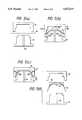
- FIGS. 5(a)-(d)are a diagrammatic sectional view of dies employed to mold the enclosure of the present invention.
- FIGS. 6(a)-(b)are a diagrammatic sectional view illustrating an enclosure and dies known in the art.
- FIGS. 7(a)-(e)are a perspective view and a sectional view illustrating another conventional art enclosure for an electronic apparatus.
- FIG. 1is a perspective view of an enclosure consisting of a box and a cover for housing electronic parts or equipment (not shown) as an embodiment of the present invention.
- the numeral 1denotes a box of the enclosure which may also be a box using the present invention or a box made of metal such as diecast aluminum.
- Numeral 2designates a cover of the enclosure using the present invention.
- the shapes of the box and coverare shown as rectangular, with a planar plate area ending substantially at an edge with side portions extending perpendicular thereto;
- box and covermay have other geometric shapes with planar plates area such as circles, triangles and the like.
- FIG. 2is a sectional view showing part of FIG. 1, wherein an electromagnetic interference shield member 21, which has been manufactured out of an extremely flexible material, i.e., a wire netting made of copper wires or the like 30 to 60 ⁇ m in diameter or a metal foil, such as a copper foil, with a plurality of small holes, is disposed in the cover 2.
- an exposed area 21a and a folded area 21b of the electromagnetic interference shield member 21At the edge of the cover 2 is an exposed area 21a and a folded area 21b of the electromagnetic interference shield member 21.
- an air vent 22where only the electromagnetic interference shield member 21 remains is provided in part of the cover 2 at the time of molding.
- an electromagnetic interference shield member 11is similarly disposed in the box 1, and as in the cover 2, an exposed area 11a and a folded area 11b are provided on the edge of the box 1.
- the folded area 11bis connected with a ground cable 12 by a bolt 13, a washer 14 and a nut 15.
- the cover 2is fitted to the box 1 in any of several conventional manners that are not illustrated, the exposed area 11a of the electromagnetic interference shield member 11 in the box 1 and the exposed area 21a of the cover 2 are brought into electrical contact with each other.
- fitting the cover of the present invention to the metal boxcauses the exposed area 21a of the cover 2 to make electrical contact with the metal box.
- FIG. 3is a perspective view of the box or cover immediately after molding.
- FIG. 4is a sectional view showing a portion of FIG. 3.
- the electromagnetic interference shield member 11 or 21is disposed so as to follow the major planar surface of the box or cover and to bend so as to make substantial contact with the intersecting point of an inner bottom or inner top plate 41 and an inner side wall 42 of the box 1 or cover 2. Further, the shield member 11 or 21 will angle from the position adjacent the intersecting inner surfaces toward the external surface of side wall 43. The shield member will exit the box or cover at an edge 44. The excess portion of the shield member may be shaped or formed around edge 44 to provide the exposed conductive surface 11a or 21a seen in FIG. 2.
- the box or cover of the enclosureis fabricated by resin molding using dies which consist of an upper die (typically a cavity) and a lower die (typically a core).
- dieswhich consist of an upper die (typically a cavity) and a lower die (typically a core).
- a molding materialis first heated, softened and fused. This molten material is subsequently injected into a space made by the combination of the upper and lower dies. After being pressed and set, the dies are opened, and finally the molded product is removed from the dies.
- the upper die and the lower die described as the cavity and the coremay also be defined as the core and the cavity, respectively.
- FIGS. 5(a)-5(d)is a diagrammatic sectional view of dies used to mold the enclosure of the present invention.
- an electromagnetic interference shield member 54 in a pre-cut stateis put on the core of the lower die 52 in a preset position by a robot or the like (not shown).
- the electromagnetic interference shield member 54is a pre-cut, planar plate-shaped wire netting made of copper wires or the like of 30 to 60 ⁇ m in diameter or a copper foil having a plurality of small holes.
- the material usedshould be sufficiently flexible so as to be shapeable by the dies without significant force.
- 5(a)-5(d)represent that the upper die 51 is at the top, the lower die 52 is at bottom, and the upper die 51 moves vertically. If the upper die 51 and lower die 52 are disposed in a horizontal direction and the upper die 51 moves in the horizontal direction, the electromagnetic interference shield member 54 may be suspended by a robot or the like (not shown) and the robot hand moved with the movement of the upper die 51. The upper die 51 is then moved toward the lower die 52 under the command of a control apparatus (which is not shown) in a movement referred to as die closing. Die closing speed is approximately 50% lower than ordinary injection molding speed.
- a gate 53 provided in the lower die 52is opened and a measured quantity of softened, fused molding material 55 begins to be injected therefrom.
- the electromagnetic interference shield member 54is bent due to the contour of the dies, as die corners 51a and 52a contact the member.
- the member 54 surfaceis further pressed against the opposed corners 52a of the lower die 52 by the opposed corners 51a of the upper die 51, the member is lightly held.
- the molding material injected from the gate 53also penetrates toward the upper die 51 through the meshed holes provided in the shield member 54. The injection speed is reduced so that the molding material does not splash or move the member 54.
- the fusing temperature of the molding materialis set as appropriate according to the type of the molding material.
- the electromagnetic interference shield member 54comes out of a gap where the outer periphery of the cavity makes contact with the outer periphery of the core to the outside of an enclosure-shaped space formed by the cavity and the core.
- the upper die 51is opened and the molded product is removed from the lower die 52, as seen in FIG. 5(d).
- the completed enclosurewill have a remainder portion 56 that can be removed or retained, as dictated by appearance requirements.
- the mesh extending from the molded productcan be shaped into an electrical contact, as in FIG. 2, or otherwise connected electrically to a ground to provide a desired EMI protection.
- normal speedmay be used for a duration until partial completion of the die closing stroke and the subsequent speed may be a reduced speed, e.g., approximately 50% of the normal speed.
- the injection of the molding material described to start midway during the period of die closingmay also be carried out after the upper die has been closed up to the final stroke if the walls of the enclosure are relatively thick.
- any of a number of injection molding materialsmay be employed, e.g., such general-purpose thermoplastic molding resins as polypropylene (P. P.), ABS, polycarbonate (PC), polyphenylene oxide (PPO) and polyamide (PA), and such engineering plastics as PA/PPO alloy and PC/PBT (polybutylene terephthalate).
- P. P.polypropylene
- PCpolycarbonate
- PPOpolyphenylene oxide
- PApolyamide
- PA/PPO alloypolybutylene terephthalate
- the molding materialmay also be thermosetting resin such as phenol resin, epoxy resin or polyurethane resin.
- thermosetting resinsuch as phenol resin, epoxy resin or polyurethane resin.
- the inventionachieves a low-priced enclosure for housing electronic parts or equipment.
- the molding processesis simplified because the electromagnetic interference shield member 54 may be used in a pre-cut, planar plate state without being preformed, and a resin molding process can be started immediately.
- the enclosurecan improve a heat dissipation effect by providing an air vent which still has the protection provided by the electromagnetic interference shield member that forms part of the enclosure.
- the inventionachieves an enclosure which does not require any special dies to expose the electromagnetic interference shield member to the exterior of the enclosure, whereby a sufficient electrical contact surface is provided if the walls of the enclosure are thin.
Landscapes
- Engineering & Computer Science (AREA)
- Mechanical Engineering (AREA)
- Microelectronics & Electronic Packaging (AREA)
- Manufacturing & Machinery (AREA)
- Chemical & Material Sciences (AREA)
- Composite Materials (AREA)
- Physics & Mathematics (AREA)
- Electromagnetism (AREA)
- Shielding Devices Or Components To Electric Or Magnetic Fields (AREA)
- Casings For Electric Apparatus (AREA)
- Injection Moulding Of Plastics Or The Like (AREA)
Abstract
Description
1. Field of the Invention
The present invention relates to an enclosure, consisting of a box or a cover for housing electronic parts or equipment to protect the electronic parts or equipment from electromagnetic interference (EMI), and to a method of manufacturing the enclosure.
2. Description of the Background Art
Electronic parts and equipment known in the art often are housed in cabinets (enclosures) made of metal which act as electromagnetic interference (EMI) shields. With the progress of technology, parts and apparatuses became more and more compact. To satisfy the demand for appropriate enclosures, plastic molded enclosures that could be efficiently produced at low costs were developed. However, such enclosures pose EMI problems.
A variety of conventional techniques are employed as the methods of EMI-shielding for plastic molded enclosures. Among these are the following: (1) a method wherein paint using a conductive material, e.g., silver or copper, as a filler, is applied to an enclosure after the molding of the enclosure, (2) a flame spraying method wherein the conductive material, e.g., silver or copper, is fused and sprayed to an enclosure by high-pressure air, (3) a vacuum metallizing method wherein metal of low boiling point (such as aluminum) is evaporated in a vacuum to form a thin film on enclosure surfaces, (4) a method wherein electroless plating of nickel, etc., is provided to an enclosure molded by high-adhesive resin, e.g., ABS resin, (5) a method wherein a molding material filled with a conductive filler, such as carbon or aluminum flakes, is used to mold an enclosure, and (6) a method wherein a composite material made by laminating a polyvinyl chloride (PVC) or polyester film to an aluminum, copper or other film is applied to an enclosure.
Also, various methods of integrally molding a metal shield material with resin have been developed.
FIG. 6(a) shows a housing for digital electronic equipment disclosed in Japanese Laid-Open Patent Publication SHO 61-22915, wherein the numeral 217' indicates resin and 215' represents a wire netting. FIG. 6(b) is a diagrammatic sectional view of dies and illustrates a molding state, wherein 211 denotes an upper die, 212 designates a lower die, 213 indicates a resin gate provided in thelower die wire netting 215 is placed on thelower die 212 and supplied with fusedresin 217 from thegate 213, theupper die 211 is subsequently closed, and thewire netting 215 is then pressed. After cooling, the molding process is complete and the enclosure is removed. In this case, the netting must be preformed in a box shape so that corners can be properly shaped in the enclosure. The preforming of the netting into other shapes is required, depending on the final shape of the enclosure.
FIG. 7(a) shows an electronic apparatus disclosed in Japanese Laid-Open Utility Model Publication SHO 63-201391, wherein 71 indicates a metal chassis containing electronic parts, electronic circuits, etc., and 73 denotes a cover. As shown in FIG. 7(b), themetal chassis 71 houseselectronic circuit cards 72. As shown in FIGS. 7(c) to 7(e), thecover 73 is made of awire netting 74 and plastics which are formed integrally, thewire netting 74 is exposed in the periphery of thecover 73 so that when thecover 73 is fitted to thechassis 71, thewire netting 74 andchassis 71 are electrically conductive. It should be noted that a cover manufacturing method is not described in this publication.
In addition to the above, a method of inserting a preformed electromagnetic interference shield material at the time of molding is disclosed in Japanese Laid-Open Utility Model Publication SHO 59-18496 and Japanese Laid-Open Patent Publication SHO 58-115894.
The conventional methods of molding an enclosure and subsequently forming a conductive film on an enclosure surface by any of conductive paint application, conductive material flame-spraying, vacuum metallizing and resin plating are high-priced and have the problem of film peeling. Also, the method of using a molding material filled with a conductive filler to mold an enclosure does not provide a uniform dispersion of the conductive filler inside a molded product and provides a poor shielding effect.
Also, the method disclosed in Japanese Laid-Open Patent Publication SHO 61-22915 required the wire netting to be preformed, resulting in a larger number of processes and higher cost. Further, the method disclosed in Japanese Laid-Open Utility Model Publication SHO 63-201391 involves high costs because one part of the enclosure was made of metal.
It is, accordingly, an object of the present invention to overcome the disadvantages in the conventional art by providing an enclosure and an enclosure manufacturing method which allow a shield material to be molded integrally with resin without pre-forming, whereby the enclosure and its manufacturing method are low in price, high in workability, and have an electromagnetic interference shielding function.
In accomplishing these and other objects of the invention, an electromagnetic interference shield member is disposed inside the molded resin in order to protect the electronic parts or electronic equipment from electromagnetic interference and the electromagnetic interference shield member is exposed at the edges of the enclosure and provides a contact or other connection to ground, even where the wall of the enclosure is thin.
The method of shaping and securing the electromagnetic interference shield member during closure of the die is a further feature of the invention in that it eliminates the need for any pre-forming of the electromagnetic interference shield member.
The provision of an excess area of the electromagnetic interference shield member so that a portion of the member extends from the outer peripheries of the cavity and core of the dies in a further feature of the invention eliminates the need for any special machining on the dies.
The air vent feature of the present invention releases high-temperature air from inside the enclosure to the outside while maintaining EMI protection.
FIG. 1 is a perspective view of an enclosure consisting of a box and a cover for housing electronic parts or equipment as a preferred embodiment of the present invention.
FIG. 2 is a sectional view illustrating some portion of FIG. 1.
FIG. 3 is a perspective view illustrating the molded enclosure of the present invention.
FIG. 4 is a sectional view illustrating some portion of FIG. 3.
FIGS. 5(a)-(d) are a diagrammatic sectional view of dies employed to mold the enclosure of the present invention.
FIGS. 6(a)-(b) are a diagrammatic sectional view illustrating an enclosure and dies known in the art.
FIGS. 7(a)-(e) are a perspective view and a sectional view illustrating another conventional art enclosure for an electronic apparatus.
FIG. 1 is a perspective view of an enclosure consisting of a box and a cover for housing electronic parts or equipment (not shown) as an embodiment of the present invention. In FIG. 1, thenumeral 1 denotes a box of the enclosure which may also be a box using the present invention or a box made of metal such as diecast aluminum.Numeral 2 designates a cover of the enclosure using the present invention. The shapes of the box and cover are shown as rectangular, with a planar plate area ending substantially at an edge with side portions extending perpendicular thereto;
but, the box and cover may have other geometric shapes with planar plates area such as circles, triangles and the like.
FIG. 2 is a sectional view showing part of FIG. 1, wherein an electromagneticinterference shield member 21, which has been manufactured out of an extremely flexible material, i.e., a wire netting made of copper wires or the like 30 to 60 μm in diameter or a metal foil, such as a copper foil, with a plurality of small holes, is disposed in thecover 2. At the edge of thecover 2 is an exposedarea 21a and a foldedarea 21b of the electromagneticinterference shield member 21. Also, anair vent 22 where only the electromagneticinterference shield member 21 remains is provided in part of thecover 2 at the time of molding. When the present invention is also used for the box, an electromagneticinterference shield member 11 is similarly disposed in thebox 1, and as in thecover 2, an exposedarea 11a and a foldedarea 11b are provided on the edge of thebox 1. The foldedarea 11b is connected with aground cable 12 by abolt 13, a washer 14 and anut 15. When thecover 2 is fitted to thebox 1 in any of several conventional manners that are not illustrated, the exposedarea 11a of the electromagneticinterference shield member 11 in thebox 1 and the exposedarea 21a of thecover 2 are brought into electrical contact with each other.
When the box is made of metal such as aluminum diecast, fitting the cover of the present invention to the metal box causes the exposedarea 21a of thecover 2 to make electrical contact with the metal box.
FIG. 3 is a perspective view of the box or cover immediately after molding. FIG. 4 is a sectional view showing a portion of FIG. 3. The electromagneticinterference shield member inner top plate 41 and aninner side wall 42 of thebox 1 orcover 2. Further, theshield member side wall 43. The shield member will exit the box or cover at anedge 44. The excess portion of the shield member may be shaped or formed aroundedge 44 to provide the exposedconductive surface
A method of manufacturing the enclosure shown in FIG. 3 will now be described. Generally, the box or cover of the enclosure is fabricated by resin molding using dies which consist of an upper die (typically a cavity) and a lower die (typically a core). To manufacture the box or cover, a molding material is first heated, softened and fused. This molten material is subsequently injected into a space made by the combination of the upper and lower dies. After being pressed and set, the dies are opened, and finally the molded product is removed from the dies.
As would be understood by one skilled in the art, the upper die and the lower die described as the cavity and the core may also be defined as the core and the cavity, respectively.
An enclosure molding method as an embodiment of the present invention will now be described in accordance with FIGS. 5(a)-5(d), which is a diagrammatic sectional view of dies used to mold the enclosure of the present invention. Referring to FIG. 5(a), when anupper die 51 and alower die 52 are open, an electromagneticinterference shield member 54 in a pre-cut state is put on the core of thelower die 52 in a preset position by a robot or the like (not shown). The electromagneticinterference shield member 54 is a pre-cut, planar plate-shaped wire netting made of copper wires or the like of 30 to 60 μm in diameter or a copper foil having a plurality of small holes. The material used should be sufficiently flexible so as to be shapeable by the dies without significant force. FIGS. 5(a)-5(d) represent that theupper die 51 is at the top, thelower die 52 is at bottom, and theupper die 51 moves vertically. If theupper die 51 andlower die 52 are disposed in a horizontal direction and theupper die 51 moves in the horizontal direction, the electromagneticinterference shield member 54 may be suspended by a robot or the like (not shown) and the robot hand moved with the movement of theupper die 51. Theupper die 51 is then moved toward thelower die 52 under the command of a control apparatus (which is not shown) in a movement referred to as die closing. Die closing speed is approximately 50% lower than ordinary injection molding speed.
Referring to FIG. 5(b), agate 53 provided in thelower die 52 is opened and a measured quantity of softened, fusedmolding material 55 begins to be injected therefrom. As also seen in the Figure, as theupper die 51 goes down, the electromagneticinterference shield member 54 is bent due to the contour of the dies, as diecorners member 54 surface is further pressed against theopposed corners 52a of thelower die 52 by theopposed corners 51a of theupper die 51, the member is lightly held. The molding material injected from thegate 53 also penetrates toward theupper die 51 through the meshed holes provided in theshield member 54. The injection speed is reduced so that the molding material does not splash or move themember 54. The fusing temperature of the molding material is set as appropriate according to the type of the molding material.
The movement of themolding material 55 through the meshes of the shield member and the contour of the dies will force the shield member to have a slightly spherical surface shape. This causes the electromagneticinterference shield member 54 to be adjacent to thegate 53 to rise from the core of thelower die 52. As die closing progresses, as seen in FIG. 5(c), the electromagneticinterference shield member 54 tends to be offset toward thelower die 52 by the pressure of themolding material 55. As a result, the electromagneticinterference shield member 54 is not exposed to the outside of the enclosure and does not mar the external surface appearance of the enclosure. At the final stroke of die closure, the electromagneticinterference shield member 54 comes out of a gap where the outer periphery of the cavity makes contact with the outer periphery of the core to the outside of an enclosure-shaped space formed by the cavity and the core.
After an appropriate setting time has elapsed following the die closing, theupper die 51 is opened and the molded product is removed from thelower die 52, as seen in FIG. 5(d). The completed enclosure will have aremainder portion 56 that can be removed or retained, as dictated by appearance requirements. The mesh extending from the molded product can be shaped into an electrical contact, as in FIG. 2, or otherwise connected electrically to a ground to provide a desired EMI protection.
Whereas the die closing speed was described as a single speed, normal speed may be used for a duration until partial completion of the die closing stroke and the subsequent speed may be a reduced speed, e.g., approximately 50% of the normal speed.
Also, the injection of the molding material described to start midway during the period of die closing may also be carried out after the upper die has been closed up to the final stroke if the walls of the enclosure are relatively thick.
As the molding material, any of a number of injection molding materials may be employed, e.g., such general-purpose thermoplastic molding resins as polypropylene (P. P.), ABS, polycarbonate (PC), polyphenylene oxide (PPO) and polyamide (PA), and such engineering plastics as PA/PPO alloy and PC/PBT (polybutylene terephthalate).
The molding material may also be thermosetting resin such as phenol resin, epoxy resin or polyurethane resin. With any of these materials, the present invention contemplates injection into the mold in a fluid or powder form followed by chemical or thermal "curing" into a hardened form.
As described above, it will be apparent that the invention achieves a low-priced enclosure for housing electronic parts or equipment. In the manufacture of this housing, the molding processes is simplified because the electromagneticinterference shield member 54 may be used in a pre-cut, planar plate state without being preformed, and a resin molding process can be started immediately. Also, the enclosure can improve a heat dissipation effect by providing an air vent which still has the protection provided by the electromagnetic interference shield member that forms part of the enclosure. Further, the invention achieves an enclosure which does not require any special dies to expose the electromagnetic interference shield member to the exterior of the enclosure, whereby a sufficient electrical contact surface is provided if the walls of the enclosure are thin.
The entire disclosure of each and every foreign patent application from which the benefit of foreign priority has been claimed in the present application is incorporated herein by reference, as if fully set forth.
Although this invention has been described in at least one preferred embodiment with a certain degree of particularity, it is to be understood that the present disclosure of the preferred embodiment has been made only by way of example and that numerous changes in the details and arrangement of components may be made without departing from the spirit and scope of the invention as hereinafter claimed.
Claims (12)
1. An EMI shielded structure for housing electronic parts or equipment comprising:
an enclosure comprising a substantially planar plate area having a first edge and at least one side wall extending substantially orthogonally to said plate area from said first edge;
said enclosure having a second edge forming an outer edge of said enclosure, said enclosure being made substantially of a molded resin;
an electromagnetic interference shield member comprising at least one of a thin, flexible wire netting or a metal foil having a plurality of small holes;
said electromagnetic interference shield member being disposed within said enclosure resin;
said electromagnetic interference shield member being slanted at said second edge of said at least one side wall of said enclosure;
said slanted portion of said electromagnetic interference shield beginning at an inner edge formed from the intersection of said side wall and said plate area of said enclosure; and
said slanted portion of said electromagnetic interference shield member extending from and being exposed at said second edge of said side wall of said enclosure.
2. The structure as defined in claim 1, wherein said exposed shield member portion comprises an electrical contact.
3. The structure as defined in claim 1, wherein said enclosure comprises an air vent connecting the interior and exterior portions of said structure, said air vent having no resin material but comprising said electromagnetic interference shield member only.
4. The structure as defined in claim 1, wherein said side wall is substantially orthogonal to said plate area.
5. A method of manufacturing an enclosure for housing electronic parts or equipment, consisting of a box or a cover having a planar surface and sides with an exposed side edge and being molded by resin, using a fixed and a moveable die, comprising the steps of:
setting a pre-cut, planar plate-shaped electromagnetic interference shield member in a position to face said fixed die, said electromagnetic interference shield member being made of a thin, flexible wire netting or a metal foil having a plurality of small holes disposed on substantially all surfaces of said enclosure, and having an area large enough to leave an excess amount of member exposed from the edges of the enclosure after the molding of the enclosure;
shaping said electromagnetic interference shield member while closing said movable die in the direction of said fixed die;
injecting a molding resin material into a space formed by said fixed die and said movable die after the start of said die closing to cause part of said molding resin material to penetrate toward said movable die through the holes of said electromagnetic interference shield member;
moving said movable die to a final die closing position for pressing said electromagnetic interference shield member and resin material into the desired shape of said enclosure while leaving an excess amount of shield member at said exposed edge or said enclosure; and
curing said shaped enclosure.
6. The method of manufacturing an EMI protected enclosure as defined in claim 5, further comprising forming an electrical contact from said excess member at said enclosure edge.
7. A method of manufacturing an EMI protected enclosure consisting of a box or a cover molded by resin for housing electronic parts or equipment, comprising the steps of:
setting a pre-cut, planar plate-shaped electromagnetic interference shield member in a position to face a fixed die, said electromagnetic interference shield member being made of a thin, flexible wire netting or a metal foil having a plurality of small holes, being disposed on substantially all surfaces of said enclosure, and having an area large enough to be exposed from the edges of the enclosure after the molding of the enclosure;
shaping and securing said electromagnetic interference shield member by closing said movable die in the direction of said fixed die;
injecting a molding resin material into a molding space formed by said fixed die and said movable die after said shaping and securing by the die closing, a portion of said material being injected through said secured shield member to completely fill said molding space; and
curing said molded resin material.
8. The method of manufacturing an EMI protected enclosure as defined in claim 7, further comprising forming an electrical contact from said excess member at said enclosure edge.
9. A method of manufacturing an EMI protected enclosure consisting of a box or a cover molded by resin for housing electronic parts or equipment, an electromagnetic interference shield member existing inside the resin, wherein said electromagnetic interference shield member is made of a thin, flexible wire netting or a metal foil having a plurality of small holes, comprising:
setting said shield member between moveable and fixed parts of a mold die, in a pre-cut, planar plate-shaped state;
at least partially shaping said member by said movable die and a fixed die by closing said mold die; and
injecting a curable plastic material into said mold die through and around said shield member.
10. A method of manufacturing an EMI protected enclosure for housing electronic parts or equipment, consisting of a box or a cover made of resin and containing within the resin an electromagnetic interference shield member and being molded by using a core die and a cavity die each of which has a respective outer periphery and which together define a mold volume having the shape of said enclosure, comprising the steps of:
setting a pre-cut, planar plate-shaped electromagnetic interference shield member in a position between said core die and said cavity die, said member having an area large enough to be exposed from the edges of the enclosure after the molding of the enclosure; and
closing said core are and cavity die whereby said electromagnetic interference shield member extends out of a gap between the outer periphery of said cavity die and the outer periphery of said core die to the outside of said mold volume.
11. An enclosure consisting of a box or a cover molded by resin for housing electronic parts or equipment, an electromagnetic interference shield member being disposed inside the resin, wherein said electromagnetic interference shield member is exposed from the intersection points of the side wall outside of said enclosure and the edges of said enclosure.
12. The structure as defined in claim 11, wherein said exposed shield member portion comprises an electrical contact.
Applications Claiming Priority (2)
| Application Number | Priority Date | Filing Date | Title |
|---|---|---|---|
| JP4-268610 | 1992-10-07 | ||
| JP4268610AJP2713059B2 (en) | 1992-10-07 | 1992-10-07 | A method for manufacturing a housing comprising a box or a lid for storing electronic components or electronic devices. |
Publications (1)
| Publication Number | Publication Date |
|---|---|
| US5473111Atrue US5473111A (en) | 1995-12-05 |
Family
ID=17460936
Family Applications (1)
| Application Number | Title | Priority Date | Filing Date |
|---|---|---|---|
| US08/120,468Expired - Fee RelatedUS5473111A (en) | 1992-10-07 | 1993-09-14 | Shielded enclosure for housing electronic components and manufacturing method thereof |
Country Status (3)
| Country | Link |
|---|---|
| US (1) | US5473111A (en) |
| JP (1) | JP2713059B2 (en) |
| DE (1) | DE4333756C2 (en) |
Cited By (71)
| Publication number | Priority date | Publication date | Assignee | Title |
|---|---|---|---|---|
| US5548083A (en)* | 1994-02-21 | 1996-08-20 | Fujitsu Limited | Shielded molded plastic cover |
| US5603196A (en)* | 1994-12-27 | 1997-02-18 | Euroshield Oy | Shield wall structure of a magnetically-shielded room and process for producing a magnetically-shielded room |
| US5641438A (en)* | 1995-01-24 | 1997-06-24 | Bunyan; Michael H. | Method for forming an EMI shielding gasket |
| US5698316A (en)* | 1996-10-07 | 1997-12-16 | The Boeing Company | Apparatus and methods of providing corrosion resistant conductive path across non conductive joints or gaps |
| US5723924A (en)* | 1995-02-08 | 1998-03-03 | Valeo Systemes D'essuyage | Motorized reduction gear unit, especially for driving a vehicle screen wiper apparatus |
| US5838542A (en)* | 1996-09-30 | 1998-11-17 | Intel Corporation | Processor card assembly including a heat sink attachment plate and an EMI/ESD shielding cage |
| WO1999015368A1 (en)* | 1997-09-22 | 1999-04-01 | Am-Safe Incorporated | Vehicle safety system |
| US5910524A (en)* | 1995-01-20 | 1999-06-08 | Parker-Hannifin Corporation | Corrosion-resistant, form-in-place EMI shielding gasket |
| AU709051B2 (en)* | 1996-01-19 | 1999-08-19 | Helmut Kahl | Electrically screening housing |
| US6046905A (en)* | 1996-09-30 | 2000-04-04 | Intel Corporation | Dual spring clip attachment mechanism for controlled pressure interface thermal solution on processor cartridges |
| WO2000002431A3 (en)* | 1998-07-07 | 2000-04-06 | Trw Automotive Electron & Comp | Housing for an electronics unit, especially an airbag control device |
| US6096413A (en)* | 1993-09-10 | 2000-08-01 | Chomerics, Inc. | Form-in-place EMI gaskets |
| US6140577A (en)* | 1998-10-08 | 2000-10-31 | Gateway 2000, Inc | Electronic chassis electro-magnetic interference seal and sealing device |
| US6140575A (en)* | 1997-10-28 | 2000-10-31 | 3Com Corporation | Shielded electronic circuit assembly |
| EP0974990A3 (en)* | 1998-07-21 | 2000-12-06 | Eaton Corporation | Insulative cover for electrical switching apparatus for electric power distribution systems |
| US6207089B1 (en)* | 1998-02-05 | 2001-03-27 | National Science Council | Process for manufacturing an electromagnetic interference shielding metallic foil cladded plastic product |
| EP1038698A3 (en)* | 1999-03-19 | 2001-08-29 | Bridgestone/Firestone, Inc. | Tire tag protector |
| EP1143561A1 (en)* | 1998-10-16 | 2001-10-10 | Société de Transformation Industrielle de Matieres Plastiques- STIMAP | Electromagnetic wave reflector and associated manufactoring method |
| US6303180B1 (en)* | 1993-09-10 | 2001-10-16 | Parker-Hannifin Corporation | Form-in-place EMI gaskets |
| US6449163B1 (en) | 1998-06-08 | 2002-09-10 | Intel Corporation | Inboard retention system for processor enclosure assemblies with substrate alignment |
| US6472014B1 (en) | 2001-04-17 | 2002-10-29 | Novellus Systems, Inc. | Uniform surface texturing for PVD/CVD hardware |
| US6515871B1 (en) | 1998-02-17 | 2003-02-04 | Intel Corporation | Protection shield for an electronic cartridge |
| US6593524B1 (en) | 2000-06-15 | 2003-07-15 | Thomas Toedtman | Device and method for providing EMI/RFI shielding |
| US6635354B2 (en) | 1995-01-20 | 2003-10-21 | Parker-Hannifin Corporation | Form-in place EMI gaskets |
| US6697248B1 (en) | 2001-02-06 | 2004-02-24 | Daniel Luch | Electromagnetic interference shields and methods of manufacture |
| US20040119201A1 (en)* | 2002-07-12 | 2004-06-24 | Siegel-Robert, Inc. | Apparatus and method for manufacturing plastic products with EMI/RFI/ESD shield |
| WO2004054940A2 (en) | 2002-12-13 | 2004-07-01 | Honeywell International Inc. | Metallic coated dielectric substrates comprising parylene polymer protective layer |
| US20040162143A1 (en)* | 2000-06-07 | 2004-08-19 | Toru Morita | Program execution system, program execution device, relay device, and recording medium |
| US20040165369A1 (en)* | 2003-02-13 | 2004-08-26 | Lionetta William G. | Combination metal and plastic EMI shield |
| US20040242104A1 (en)* | 2002-12-18 | 2004-12-02 | Meridian Automotive Systems, Inc. | Composite engine component and method for making the same |
| US20050008848A1 (en)* | 2001-01-29 | 2005-01-13 | Saccomanno Robert J. | Barrier coating composition for a substrate |
| US6943288B1 (en) | 2004-06-04 | 2005-09-13 | Schlegel Systems, Inc. | EMI foil laminate gasket |
| US7005573B2 (en) | 2003-02-13 | 2006-02-28 | Parker-Hannifin Corporation | Composite EMI shield |
| US20060084289A1 (en)* | 2004-10-19 | 2006-04-20 | Ziberna Frank J | Apparatus and method for shielding printed circuit boards |
| US20070137653A1 (en)* | 2000-03-13 | 2007-06-21 | Wood Thomas J | Ventilation interface for sleep apnea therapy |
| WO2008024251A3 (en)* | 2006-08-18 | 2008-07-17 | Delphi Tech Inc | Lightweight audio system for automotive applications and method |
| US20080185478A1 (en)* | 2006-10-26 | 2008-08-07 | Airbus Deutschland Gmbh | Line system for an aircraft |
| US20090008146A1 (en)* | 2007-03-16 | 2009-01-08 | Michael William Oleske | Optimizing in-building wireless signal propagation while ensuring data network security |
| US7518880B1 (en) | 2006-02-08 | 2009-04-14 | Bi-Link | Shielding arrangement for electronic device |
| US20090320892A1 (en)* | 2008-06-30 | 2009-12-31 | Electrolux Home Products, Inc. | Protective arrangement for a control device associated with a dishwashing appliance, and associated apparatus and method |
| US20090320886A1 (en)* | 2008-06-30 | 2009-12-31 | Electrolux Home Products, Inc. | Protective arrangement for a control device associated with a dishwashing appliance, and associated apparatus and method |
| US7665761B1 (en) | 2008-03-27 | 2010-02-23 | Amsafe, Inc. | Inflatable personal restraint systems and associated methods of use and manufacture |
| US20100128456A1 (en)* | 2008-11-26 | 2010-05-27 | Flir Systems, Inc. | Electronic Package |
| US20100246155A1 (en)* | 2006-08-18 | 2010-09-30 | Delphi Technologies, Inc. | Lightweight audio system for automotive applications and method |
| US20100257732A1 (en)* | 2009-04-14 | 2010-10-14 | Ziberna Frank J | Shielding Arrangement for Electronic Device |
| US20110018160A1 (en)* | 2009-07-24 | 2011-01-27 | Ziberna Frank J | Method of Producing Covers for Electronics |
| US20110128715A1 (en)* | 2009-12-01 | 2011-06-02 | Fujitsu Limited | Shield case and communication device |
| US7980590B2 (en) | 2008-03-19 | 2011-07-19 | Amsafe, Inc. | Inflatable personal restraint systems having web-mounted inflators and associated methods of use and manufacture |
| US20110261588A1 (en)* | 2009-06-18 | 2011-10-27 | Mitsubishi Heavy Industries, Ltd. | Inverter module and integrated-inverter electric compressor using the same |
| US20120010336A1 (en)* | 2009-01-26 | 2012-01-12 | Levchik Sergei V | Flame retarded thermoplastic composition, process for making same and article containing same |
| US8151127B2 (en) | 2000-07-26 | 2012-04-03 | Bridgestone Americas Tire Operations, Llc | System for conserving battery life in a battery operated device |
| US20120193137A1 (en)* | 2005-03-15 | 2012-08-02 | Paul Douglas Cochrane | EMI-Shielding Solutions for Computer Enclosures Using Combinations of Two and Three-Dimensional Shapes Formed in Sheet Metal |
| US8266465B2 (en) | 2000-07-26 | 2012-09-11 | Bridgestone Americas Tire Operation, LLC | System for conserving battery life in a battery operated device |
| US8439398B2 (en) | 2011-07-29 | 2013-05-14 | Amsafe, Inc. | Inflator connectors for inflatable personal restraints and associated systems and methods |
| RU2483502C2 (en)* | 2009-08-18 | 2013-05-27 | БАРТЕК ГмбХ | Vessel for electric equipment |
| US8469397B2 (en) | 2011-04-13 | 2013-06-25 | Amsafe, Inc. | Stitch patterns for restraint-mounted airbags and associated systems and methods |
| US8523220B1 (en) | 2012-03-19 | 2013-09-03 | Amsafe, Inc. | Structure mounted airbag assemblies and associated systems and methods |
| US8760886B2 (en) | 2006-08-18 | 2014-06-24 | Delphi Technologies, Inc. | Lightweight audio system for automotive applications and method |
| US20140190841A1 (en)* | 2010-09-07 | 2014-07-10 | Michael J. Nash | Data signal blocking personal communication device holder |
| US9237685B2 (en) | 2006-08-18 | 2016-01-12 | Delphi Technologies, Inc. | Lightweight audio system for automotive applications and method |
| CN105307848A (en)* | 2013-07-05 | 2016-02-03 | 宝马股份公司 | Method for producing an electrical and/or magnetic radiation shielding housing and an electrical and/or magnetic radiation shielding housing |
| US9352839B2 (en) | 2014-10-02 | 2016-05-31 | Amsafe, Inc. | Active positioning airbag assembly and associated systems and methods |
| US9511866B2 (en) | 2012-03-19 | 2016-12-06 | Amsafe, Inc. | Structure mounted airbag assemblies and associated systems and methods |
| EP3196461A3 (en)* | 2016-01-15 | 2017-10-11 | Whirlpool S.A. | System, method and means for connecting and fixing an electronic control to an airtight compressor and an airtight compressor |
| US9925950B2 (en) | 2015-04-11 | 2018-03-27 | Amsafe, Inc. | Active airbag vent system |
| US9944245B2 (en) | 2015-03-28 | 2018-04-17 | Amsafe, Inc. | Extending pass-through airbag occupant restraint systems, and associated systems and methods |
| CN110198824A (en)* | 2017-01-19 | 2019-09-03 | 代傲阿扣基金两合公司 | For manufacturing the method and electromagnetic compatible shielding shell of electromagnetic compatible shielding shell |
| US10604259B2 (en) | 2016-01-20 | 2020-03-31 | Amsafe, Inc. | Occupant restraint systems having extending restraints, and associated systems and methods |
| JP2023067390A (en)* | 2021-11-01 | 2023-05-16 | 古河電気工業株式会社 | shield housing |
| WO2023123181A1 (en)* | 2021-12-30 | 2023-07-06 | Sabic Global Technologies B.V. | Electronics enclosure with 3-dimensional overmolded mesh |
| US20250056775A1 (en)* | 2021-12-16 | 2025-02-13 | Continental Autonomous Mobility Germany GmbH | Housing with shielding for electromagnetic radiation |
Families Citing this family (13)
| Publication number | Priority date | Publication date | Assignee | Title |
|---|---|---|---|---|
| US7732732B2 (en) | 1996-11-20 | 2010-06-08 | Ibiden Co., Ltd. | Laser machining apparatus, and apparatus and method for manufacturing a multilayered printed wiring board |
| US7462801B1 (en) | 1996-11-20 | 2008-12-09 | Ibiden Co., Ltd. | Laser machining apparatus, and apparatus and method for manufacturing a multilayered printed wiring board |
| JP3250140B2 (en)* | 1996-12-12 | 2002-01-28 | 三菱電機株式会社 | Radio shield device |
| DE19801985C2 (en)* | 1998-01-20 | 2003-07-03 | Mcgavigan John Ltd | Three-dimensional deformable, multi-layer laminate and processing into a screen housing |
| DE10353384A1 (en)* | 2003-11-14 | 2005-06-23 | Leoni Ag | A space surrounded by walls and method of forming an antenna or shield |
| DE102005005252B4 (en)* | 2005-02-04 | 2010-04-29 | Knorr-Bremse Systeme für Nutzfahrzeuge GmbH | contactor |
| JP2011198836A (en)* | 2010-03-17 | 2011-10-06 | Denso Corp | Electronic device |
| FR2963764B1 (en)* | 2010-08-10 | 2012-07-27 | Peugeot Citroen Automobiles Sa | SYSTEM FOR CLEANING THE GLASS OF A MOTOR VEHICLE |
| CN102548290B (en)* | 2010-12-09 | 2016-06-01 | 中山市云创知识产权服务有限公司 | Electronic equipment chassis |
| DE102014211824A1 (en)* | 2014-06-20 | 2015-12-24 | Robert Bosch Gmbh | Housing, in particular for receiving an electronic circuit and method for producing a housing |
| DE102016008369B4 (en) | 2016-07-08 | 2024-07-18 | Audi Ag | Method for producing a shielding housing part and shielding housing part produced thereby for vehicle applications |
| WO2019193716A1 (en)* | 2018-04-05 | 2019-10-10 | 三菱電機株式会社 | Motor, valve, actuator, and method for manufacturing motor |
| DE102018132886B3 (en)* | 2018-12-19 | 2019-12-12 | d&b audiotechnik Verwaltungs GmbH | Method for producing a plastic-coated loudspeaker housing and plastic-coated loudspeaker housing |
Citations (15)
| Publication number | Priority date | Publication date | Assignee | Title |
|---|---|---|---|---|
| US4381421A (en)* | 1980-07-01 | 1983-04-26 | Tektronix, Inc. | Electromagnetic shield for electronic equipment |
| JPS58115894A (en)* | 1981-12-28 | 1983-07-09 | ソニー株式会社 | Housing for electronic equipment and method of producing same |
| JPS5918496A (en)* | 1982-07-23 | 1984-01-30 | 株式会社東芝 | Dehumidification method for gaseous waste treatment system |
| JPS6122915A (en)* | 1984-07-11 | 1986-01-31 | Sumitomo Chem Co Ltd | Press molding method for thermoplastic resin |
| US4608453A (en)* | 1984-08-20 | 1986-08-26 | The Budd Company | Electro-magnetic interference shield |
| DE3608938A1 (en)* | 1986-03-18 | 1987-09-24 | Julius Dipl Ing Giliard | Composite material of synthetic resin, in particular glass fibre-reinforced synthetic resin, and metal |
| JPS63201391A (en)* | 1987-02-16 | 1988-08-19 | Hitachi Ltd | Rotary hermetic compressor |
| US4777565A (en)* | 1986-03-15 | 1988-10-11 | Unisys Corporation | Shielded equipment enclosure |
| DE3838901A1 (en)* | 1988-11-17 | 1990-05-23 | Pag Presswerk Ag | Plastic enclosure and process for its production |
| US4941207A (en)* | 1984-05-01 | 1990-07-10 | Nihon Musen Kabushiki Kaisha | Structure for wireless communication in an electromagnetically shielded building |
| US5008487A (en)* | 1988-08-09 | 1991-04-16 | Kabushiki Kaisha Toshiba | Casing structure |
| US5137766A (en)* | 1988-03-29 | 1992-08-11 | Bayer Aktiengesellschaft | Metal fibre-containing composite materials and use thereof for producing mouldings for screening against electromagnetic radiation |
| US5150282A (en)* | 1990-12-14 | 1992-09-22 | Fujitsu Limited | Electromagnetic shielding structure of high-frequency circuit arrangements |
| US5204497A (en)* | 1990-05-30 | 1993-04-20 | Zeos International, Inc. | Computer front panel with offset airflow louvers |
| US5239125A (en)* | 1990-06-19 | 1993-08-24 | The United States Of America As Represented By The Secretary Of The Army | EMI/RFI shield |
Family Cites Families (6)
| Publication number | Priority date | Publication date | Assignee | Title |
|---|---|---|---|---|
| JPS5918496U (en)* | 1982-07-27 | 1984-02-04 | 東芝ケミカル株式会社 | Electromagnetic shield case |
| JPS60177699A (en)* | 1984-02-24 | 1985-09-11 | 昭和電工株式会社 | Method of producing electromagnetic wave shielding housing |
| JPS60253297A (en)* | 1984-05-29 | 1985-12-13 | 大日本印刷株式会社 | Molded body for electromagnetic shielding and its manufacturing method |
| JPS6237996U (en)* | 1985-08-27 | 1987-03-06 | ||
| JPH0648955Y2 (en)* | 1987-06-16 | 1994-12-12 | 日本電気株式会社 | Electronic device cover |
| JPH01161895A (en)* | 1987-12-18 | 1989-06-26 | Tokyo Keiki Co Ltd | Electromagnetic shielding panel |
- 1992
- 1992-10-07JPJP4268610Apatent/JP2713059B2/ennot_activeExpired - Lifetime
- 1993
- 1993-09-14USUS08/120,468patent/US5473111A/ennot_activeExpired - Fee Related
- 1993-10-04DEDE4333756Apatent/DE4333756C2/ennot_activeExpired - Fee Related
Patent Citations (15)
| Publication number | Priority date | Publication date | Assignee | Title |
|---|---|---|---|---|
| US4381421A (en)* | 1980-07-01 | 1983-04-26 | Tektronix, Inc. | Electromagnetic shield for electronic equipment |
| JPS58115894A (en)* | 1981-12-28 | 1983-07-09 | ソニー株式会社 | Housing for electronic equipment and method of producing same |
| JPS5918496A (en)* | 1982-07-23 | 1984-01-30 | 株式会社東芝 | Dehumidification method for gaseous waste treatment system |
| US4941207A (en)* | 1984-05-01 | 1990-07-10 | Nihon Musen Kabushiki Kaisha | Structure for wireless communication in an electromagnetically shielded building |
| JPS6122915A (en)* | 1984-07-11 | 1986-01-31 | Sumitomo Chem Co Ltd | Press molding method for thermoplastic resin |
| US4608453A (en)* | 1984-08-20 | 1986-08-26 | The Budd Company | Electro-magnetic interference shield |
| US4777565A (en)* | 1986-03-15 | 1988-10-11 | Unisys Corporation | Shielded equipment enclosure |
| DE3608938A1 (en)* | 1986-03-18 | 1987-09-24 | Julius Dipl Ing Giliard | Composite material of synthetic resin, in particular glass fibre-reinforced synthetic resin, and metal |
| JPS63201391A (en)* | 1987-02-16 | 1988-08-19 | Hitachi Ltd | Rotary hermetic compressor |
| US5137766A (en)* | 1988-03-29 | 1992-08-11 | Bayer Aktiengesellschaft | Metal fibre-containing composite materials and use thereof for producing mouldings for screening against electromagnetic radiation |
| US5008487A (en)* | 1988-08-09 | 1991-04-16 | Kabushiki Kaisha Toshiba | Casing structure |
| DE3838901A1 (en)* | 1988-11-17 | 1990-05-23 | Pag Presswerk Ag | Plastic enclosure and process for its production |
| US5204497A (en)* | 1990-05-30 | 1993-04-20 | Zeos International, Inc. | Computer front panel with offset airflow louvers |
| US5239125A (en)* | 1990-06-19 | 1993-08-24 | The United States Of America As Represented By The Secretary Of The Army | EMI/RFI shield |
| US5150282A (en)* | 1990-12-14 | 1992-09-22 | Fujitsu Limited | Electromagnetic shielding structure of high-frequency circuit arrangements |
Cited By (127)
| Publication number | Priority date | Publication date | Assignee | Title |
|---|---|---|---|---|
| US6303180B1 (en)* | 1993-09-10 | 2001-10-16 | Parker-Hannifin Corporation | Form-in-place EMI gaskets |
| US6331349B1 (en) | 1993-09-10 | 2001-12-18 | Parker-Hannifin Corporation | Form-in-place EMI gaskets |
| US6096413A (en)* | 1993-09-10 | 2000-08-01 | Chomerics, Inc. | Form-in-place EMI gaskets |
| US5755915A (en)* | 1994-02-21 | 1998-05-26 | Fujitsu Limited | Method for producing a shielding molded plastic part |
| US5548083A (en)* | 1994-02-21 | 1996-08-20 | Fujitsu Limited | Shielded molded plastic cover |
| US5792482A (en)* | 1994-02-21 | 1998-08-11 | Fujitsu Limited | Apparatus for producing a plastic molded product |
| US5603196A (en)* | 1994-12-27 | 1997-02-18 | Euroshield Oy | Shield wall structure of a magnetically-shielded room and process for producing a magnetically-shielded room |
| US6635354B2 (en) | 1995-01-20 | 2003-10-21 | Parker-Hannifin Corporation | Form-in place EMI gaskets |
| US5910524A (en)* | 1995-01-20 | 1999-06-08 | Parker-Hannifin Corporation | Corrosion-resistant, form-in-place EMI shielding gasket |
| US5641438A (en)* | 1995-01-24 | 1997-06-24 | Bunyan; Michael H. | Method for forming an EMI shielding gasket |
| US6056527A (en)* | 1995-01-24 | 2000-05-02 | Bunyan; Michael H. | Apparatus for forming a gasket |
| US5723924A (en)* | 1995-02-08 | 1998-03-03 | Valeo Systemes D'essuyage | Motorized reduction gear unit, especially for driving a vehicle screen wiper apparatus |
| AU709051B2 (en)* | 1996-01-19 | 1999-08-19 | Helmut Kahl | Electrically screening housing |
| US6046905A (en)* | 1996-09-30 | 2000-04-04 | Intel Corporation | Dual spring clip attachment mechanism for controlled pressure interface thermal solution on processor cartridges |
| US5838542A (en)* | 1996-09-30 | 1998-11-17 | Intel Corporation | Processor card assembly including a heat sink attachment plate and an EMI/ESD shielding cage |
| US6381136B1 (en) | 1996-09-30 | 2002-04-30 | Intel Corporation | Dual spring clip attachment mechanism for controlled pressure interface thermal solution on processor cartridges |
| US5698316A (en)* | 1996-10-07 | 1997-12-16 | The Boeing Company | Apparatus and methods of providing corrosion resistant conductive path across non conductive joints or gaps |
| US5984350A (en)* | 1997-09-22 | 1999-11-16 | Am-Safe, Inc. | Vehicle safety system |
| WO1999015368A1 (en)* | 1997-09-22 | 1999-04-01 | Am-Safe Incorporated | Vehicle safety system |
| US6140575A (en)* | 1997-10-28 | 2000-10-31 | 3Com Corporation | Shielded electronic circuit assembly |
| US6207089B1 (en)* | 1998-02-05 | 2001-03-27 | National Science Council | Process for manufacturing an electromagnetic interference shielding metallic foil cladded plastic product |
| US6515871B1 (en) | 1998-02-17 | 2003-02-04 | Intel Corporation | Protection shield for an electronic cartridge |
| US6449163B1 (en) | 1998-06-08 | 2002-09-10 | Intel Corporation | Inboard retention system for processor enclosure assemblies with substrate alignment |
| WO2000002431A3 (en)* | 1998-07-07 | 2000-04-06 | Trw Automotive Electron & Comp | Housing for an electronics unit, especially an airbag control device |
| US6439927B1 (en) | 1998-07-07 | 2002-08-27 | Trw Automotive Electronics & Components Gmbh & Co. Kg | Shielded housing for holding electronic components, particularly electronic air bag control devices |
| KR100411563B1 (en)* | 1998-07-07 | 2003-12-18 | 테에르베 오토모티브 일렉트로닉스 운트 콤포넌츠 게엠베하 운트 코. 카게 | Housing for an electronics unit, especially an airbag control device |
| EP0974990A3 (en)* | 1998-07-21 | 2000-12-06 | Eaton Corporation | Insulative cover for electrical switching apparatus for electric power distribution systems |
| US6140577A (en)* | 1998-10-08 | 2000-10-31 | Gateway 2000, Inc | Electronic chassis electro-magnetic interference seal and sealing device |
| EP1143561A1 (en)* | 1998-10-16 | 2001-10-10 | Société de Transformation Industrielle de Matieres Plastiques- STIMAP | Electromagnetic wave reflector and associated manufactoring method |
| EP1038698A3 (en)* | 1999-03-19 | 2001-08-29 | Bridgestone/Firestone, Inc. | Tire tag protector |
| US6312539B1 (en) | 1999-03-19 | 2001-11-06 | Bridgestone/Firestone Research, Inc. | Method of using tire tag protector |
| US20070137653A1 (en)* | 2000-03-13 | 2007-06-21 | Wood Thomas J | Ventilation interface for sleep apnea therapy |
| US20040162143A1 (en)* | 2000-06-07 | 2004-08-19 | Toru Morita | Program execution system, program execution device, relay device, and recording medium |
| US6593524B1 (en) | 2000-06-15 | 2003-07-15 | Thomas Toedtman | Device and method for providing EMI/RFI shielding |
| US8151127B2 (en) | 2000-07-26 | 2012-04-03 | Bridgestone Americas Tire Operations, Llc | System for conserving battery life in a battery operated device |
| US8266465B2 (en) | 2000-07-26 | 2012-09-11 | Bridgestone Americas Tire Operation, LLC | System for conserving battery life in a battery operated device |
| US20050008848A1 (en)* | 2001-01-29 | 2005-01-13 | Saccomanno Robert J. | Barrier coating composition for a substrate |
| US6906257B2 (en) | 2001-01-29 | 2005-06-14 | Honeywell International Inc. | Metallic coated dielectric substrates |
| US6697248B1 (en) | 2001-02-06 | 2004-02-24 | Daniel Luch | Electromagnetic interference shields and methods of manufacture |
| US6472014B1 (en) | 2001-04-17 | 2002-10-29 | Novellus Systems, Inc. | Uniform surface texturing for PVD/CVD hardware |
| US20040119201A1 (en)* | 2002-07-12 | 2004-06-24 | Siegel-Robert, Inc. | Apparatus and method for manufacturing plastic products with EMI/RFI/ESD shield |
| WO2004054940A2 (en) | 2002-12-13 | 2004-07-01 | Honeywell International Inc. | Metallic coated dielectric substrates comprising parylene polymer protective layer |
| US20040242104A1 (en)* | 2002-12-18 | 2004-12-02 | Meridian Automotive Systems, Inc. | Composite engine component and method for making the same |
| US20040165369A1 (en)* | 2003-02-13 | 2004-08-26 | Lionetta William G. | Combination metal and plastic EMI shield |
| US7326862B2 (en) | 2003-02-13 | 2008-02-05 | Parker-Hannifin Corporation | Combination metal and plastic EMI shield |
| US7005573B2 (en) | 2003-02-13 | 2006-02-28 | Parker-Hannifin Corporation | Composite EMI shield |
| US6943288B1 (en) | 2004-06-04 | 2005-09-13 | Schlegel Systems, Inc. | EMI foil laminate gasket |
| US7087835B2 (en) | 2004-10-19 | 2006-08-08 | Bi-Link Metal Specialties Inc. | Apparatus and method for shielding printed circuit boards |
| US20060084289A1 (en)* | 2004-10-19 | 2006-04-20 | Ziberna Frank J | Apparatus and method for shielding printed circuit boards |
| US8399780B2 (en)* | 2005-03-15 | 2013-03-19 | Stealthdrive, Inc. | EMI-shielding solutions for computer enclosures using combinations of two and three-dimensional shapes formed in sheet metal |
| US20120193137A1 (en)* | 2005-03-15 | 2012-08-02 | Paul Douglas Cochrane | EMI-Shielding Solutions for Computer Enclosures Using Combinations of Two and Three-Dimensional Shapes Formed in Sheet Metal |
| US7518880B1 (en) | 2006-02-08 | 2009-04-14 | Bi-Link | Shielding arrangement for electronic device |
| US8625293B2 (en) | 2006-08-18 | 2014-01-07 | Delphi Technologies, Inc. | Lightweight audio system for automotive applications and method |
| EP2055160A4 (en)* | 2006-08-18 | 2012-03-28 | Delphi Tech Inc | Lightweight audio system for automotive applications and method |
| US9237685B2 (en) | 2006-08-18 | 2016-01-12 | Delphi Technologies, Inc. | Lightweight audio system for automotive applications and method |
| US7733659B2 (en) | 2006-08-18 | 2010-06-08 | Delphi Technologies, Inc. | Lightweight audio system for automotive applications and method |
| US20100186217A1 (en)* | 2006-08-18 | 2010-07-29 | Delphi Technologies, Inc. | Lightweight audio system for automotive applications and method |
| US20100202623A1 (en)* | 2006-08-18 | 2010-08-12 | Snider Chris R | Lightweight audio system for automotive applications and method |
| US20100205622A1 (en)* | 2006-08-18 | 2010-08-12 | Snider Chris R | Lightweight audio system for automotive applications and method |
| US20100246155A1 (en)* | 2006-08-18 | 2010-09-30 | Delphi Technologies, Inc. | Lightweight audio system for automotive applications and method |
| US9237683B2 (en) | 2006-08-18 | 2016-01-12 | Delphi Technologies, Inc. | Lightweight audio system for automotive applications and method |
| EP2055161A4 (en)* | 2006-08-18 | 2010-12-29 | Delphi Tech Inc | Lightweight audio system for automotive applications and method |
| US9173332B2 (en) | 2006-08-18 | 2015-10-27 | Delphi Technologies, Inc. | Lightweight audio system for automotive applications and method |
| US9119288B2 (en) | 2006-08-18 | 2015-08-25 | Delphi Technologies, Inc. | Lightweight audio system for automotive applications and method |
| US9013881B2 (en) | 2006-08-18 | 2015-04-21 | Delphi Technologies, Inc. | Lightweight audio system for automotive applications and method |
| US8035976B2 (en) | 2006-08-18 | 2011-10-11 | Delphi Technologies, Inc. | Lightweight audio system for automotive applications and method |
| US8988884B2 (en) | 2006-08-18 | 2015-03-24 | Delphi Technologies, Inc | Lightweight audio system for automotive applications and method |
| US8087165B2 (en) | 2006-08-18 | 2012-01-03 | Delphi Technologies, Inc. | Lightweight audio system for automotive applications and method |
| US8982561B2 (en) | 2006-08-18 | 2015-03-17 | Delphi Technologies, Inc. | Lightweight audio system for automotive applications and method |
| US8570757B2 (en) | 2006-08-18 | 2013-10-29 | Delphi Technologies, Inc. | Lightweight audio system for automotive applications and method |
| EP2055010A4 (en)* | 2006-08-18 | 2012-03-14 | Delphi Tech Inc | Lightweight audio system for automotive applications and method |
| US8593821B2 (en) | 2006-08-18 | 2013-11-26 | Delphi Technologies, Inc. | Lightweight audio system for automotive applications and method |
| US8947860B2 (en) | 2006-08-18 | 2015-02-03 | Delphi Technologies, Inc. | Lightweight audio system for automotive applications and method |
| US8830687B2 (en) | 2006-08-18 | 2014-09-09 | Delphi Technologies, Inc. | Lightweight audio system for automotive applications and method |
| US8760886B2 (en) | 2006-08-18 | 2014-06-24 | Delphi Technologies, Inc. | Lightweight audio system for automotive applications and method |
| US8599568B2 (en) | 2006-08-18 | 2013-12-03 | Delphi Technologies, Inc. | Lightweight audio system for automotive applications and method |
| US8284559B2 (en) | 2006-08-18 | 2012-10-09 | Delphi Technologies, Inc. | Lightweight audio system for automotive applications and method |
| US8749988B2 (en) | 2006-08-18 | 2014-06-10 | Delphi Technologies, Inc. | Lightweight audio system for automotive applications and method |
| US8305773B2 (en) | 2006-08-18 | 2012-11-06 | Delphi Technologies, Inc. | Lightweight audio system for automotive applications and method |
| EP2544375A1 (en)* | 2006-08-18 | 2013-01-09 | Delphi Technologies, Inc. | Lightweight audio system for automotive applications and method |
| US8731862B2 (en) | 2006-08-18 | 2014-05-20 | Delphi Technologies, Inc. | Lightweight audio system for automotive applications and method |
| US8498126B2 (en) | 2006-08-18 | 2013-07-30 | Delphi Technologies, Inc. | Lightweight audio system for automotive applications and method |
| US8724335B2 (en) | 2006-08-18 | 2014-05-13 | Delphi Technologies, Inc. | Lightweight audio system for automotive applications and method |
| US8625292B2 (en) | 2006-08-18 | 2014-01-07 | Delphi Technologies, Inc. | Lightweight audio system for automotive applications and method |
| WO2008024251A3 (en)* | 2006-08-18 | 2008-07-17 | Delphi Tech Inc | Lightweight audio system for automotive applications and method |
| US8477509B2 (en) | 2006-08-18 | 2013-07-02 | Delphi Technologies, Inc. | Lightweight audio system for automotive applications and method |
| US8493739B2 (en) | 2006-08-18 | 2013-07-23 | Delphi Technologies, Inc. | Lightweight audio system for automotive applications and method |
| US20080185478A1 (en)* | 2006-10-26 | 2008-08-07 | Airbus Deutschland Gmbh | Line system for an aircraft |
| US8128030B2 (en)* | 2006-10-26 | 2012-03-06 | Airbus Operations Gmbh | Line system for an aircraft |
| US20090008146A1 (en)* | 2007-03-16 | 2009-01-08 | Michael William Oleske | Optimizing in-building wireless signal propagation while ensuring data network security |
| US9125293B2 (en) | 2007-08-15 | 2015-09-01 | Delphi Technologies, Inc. | Lightweight audio system for automotive applications and method |
| US7980590B2 (en) | 2008-03-19 | 2011-07-19 | Amsafe, Inc. | Inflatable personal restraint systems having web-mounted inflators and associated methods of use and manufacture |
| US7665761B1 (en) | 2008-03-27 | 2010-02-23 | Amsafe, Inc. | Inflatable personal restraint systems and associated methods of use and manufacture |
| US8398782B2 (en)* | 2008-06-30 | 2013-03-19 | Electrolux Home Products, Inc. | Protective arrangement for a control device associated with a dishwashing appliance, and associated apparatus and method |
| US8293027B2 (en) | 2008-06-30 | 2012-10-23 | Electrolux Home Products, Inc. | Protective arrangement for a control device associated with a dishwashing appliance, and associated apparatus and method |
| US20090320892A1 (en)* | 2008-06-30 | 2009-12-31 | Electrolux Home Products, Inc. | Protective arrangement for a control device associated with a dishwashing appliance, and associated apparatus and method |
| US20090320886A1 (en)* | 2008-06-30 | 2009-12-31 | Electrolux Home Products, Inc. | Protective arrangement for a control device associated with a dishwashing appliance, and associated apparatus and method |
| US8173911B2 (en)* | 2008-11-26 | 2012-05-08 | Flir Systems, Inc. | Electronic package |
| US20100128456A1 (en)* | 2008-11-26 | 2010-05-27 | Flir Systems, Inc. | Electronic Package |
| US20120010336A1 (en)* | 2009-01-26 | 2012-01-12 | Levchik Sergei V | Flame retarded thermoplastic composition, process for making same and article containing same |
| US20100257732A1 (en)* | 2009-04-14 | 2010-10-14 | Ziberna Frank J | Shielding Arrangement for Electronic Device |
| US9115707B2 (en)* | 2009-06-18 | 2015-08-25 | Mitsubishi Heavy Industries, Ltd. | Inverter module and integrated-inverter electric compressor using the same |
| US20110261588A1 (en)* | 2009-06-18 | 2011-10-27 | Mitsubishi Heavy Industries, Ltd. | Inverter module and integrated-inverter electric compressor using the same |
| US20110018160A1 (en)* | 2009-07-24 | 2011-01-27 | Ziberna Frank J | Method of Producing Covers for Electronics |
| RU2483502C2 (en)* | 2009-08-18 | 2013-05-27 | БАРТЕК ГмбХ | Vessel for electric equipment |
| US8570766B2 (en)* | 2009-12-01 | 2013-10-29 | Fujitsu Limited | Shield case and communication device |
| US20110128715A1 (en)* | 2009-12-01 | 2011-06-02 | Fujitsu Limited | Shield case and communication device |
| US10405622B2 (en) | 2010-09-07 | 2019-09-10 | Caged Idea's Llc | Data signal blocking personal communication device holder |
| US20140190841A1 (en)* | 2010-09-07 | 2014-07-10 | Michael J. Nash | Data signal blocking personal communication device holder |
| US9655419B2 (en)* | 2010-09-07 | 2017-05-23 | Michael J. Nash | Data signal blocking personal communication device holder |
| US8469397B2 (en) | 2011-04-13 | 2013-06-25 | Amsafe, Inc. | Stitch patterns for restraint-mounted airbags and associated systems and methods |
| US8439398B2 (en) | 2011-07-29 | 2013-05-14 | Amsafe, Inc. | Inflator connectors for inflatable personal restraints and associated systems and methods |
| US8523220B1 (en) | 2012-03-19 | 2013-09-03 | Amsafe, Inc. | Structure mounted airbag assemblies and associated systems and methods |
| US9511866B2 (en) | 2012-03-19 | 2016-12-06 | Amsafe, Inc. | Structure mounted airbag assemblies and associated systems and methods |
| US9889937B2 (en) | 2012-03-19 | 2018-02-13 | Amsafe, Inc. | Structure mounted airbag assemblies and associated systems and methods |
| CN105307848A (en)* | 2013-07-05 | 2016-02-03 | 宝马股份公司 | Method for producing an electrical and/or magnetic radiation shielding housing and an electrical and/or magnetic radiation shielding housing |
| US20160044840A1 (en)* | 2013-07-05 | 2016-02-11 | Bayerische Motoren Werke Aktiengesellschaft | Method for Producing a Housing Having Shielding Against Electric and/or Magnetic Radiation, and Housing Having the Shielding |
| US10492347B2 (en)* | 2013-07-05 | 2019-11-26 | Bayerische Motoren Werke Aktiengesellschaft | Method for producing a housing having shielding against electric and/or magnetic radiation, and housing having the shielding |
| US9352839B2 (en) | 2014-10-02 | 2016-05-31 | Amsafe, Inc. | Active positioning airbag assembly and associated systems and methods |
| US9944245B2 (en) | 2015-03-28 | 2018-04-17 | Amsafe, Inc. | Extending pass-through airbag occupant restraint systems, and associated systems and methods |
| US9925950B2 (en) | 2015-04-11 | 2018-03-27 | Amsafe, Inc. | Active airbag vent system |
| EP3196461A3 (en)* | 2016-01-15 | 2017-10-11 | Whirlpool S.A. | System, method and means for connecting and fixing an electronic control to an airtight compressor and an airtight compressor |
| US10604259B2 (en) | 2016-01-20 | 2020-03-31 | Amsafe, Inc. | Occupant restraint systems having extending restraints, and associated systems and methods |
| CN110198824A (en)* | 2017-01-19 | 2019-09-03 | 代傲阿扣基金两合公司 | For manufacturing the method and electromagnetic compatible shielding shell of electromagnetic compatible shielding shell |
| JP2023067390A (en)* | 2021-11-01 | 2023-05-16 | 古河電気工業株式会社 | shield housing |
| US20250056775A1 (en)* | 2021-12-16 | 2025-02-13 | Continental Autonomous Mobility Germany GmbH | Housing with shielding for electromagnetic radiation |
| WO2023123181A1 (en)* | 2021-12-30 | 2023-07-06 | Sabic Global Technologies B.V. | Electronics enclosure with 3-dimensional overmolded mesh |
Also Published As
| Publication number | Publication date |
|---|---|
| DE4333756A1 (en) | 1994-04-14 |
| JPH06120683A (en) | 1994-04-28 |
| JP2713059B2 (en) | 1998-02-16 |
| DE4333756C2 (en) | 1998-02-12 |
Similar Documents
| Publication | Publication Date | Title |
|---|---|---|
| US5473111A (en) | Shielded enclosure for housing electronic components and manufacturing method thereof | |
| CN104602476B (en) | Housing, the electronic installation and preparation method thereof using the housing | |
| US5867370A (en) | Plastic shield enclosure and method of producing the same | |
| US6865805B2 (en) | Device and method of forming a unitary electrically shielded panel | |
| WO2002024431A1 (en) | Multi-layered structures and methods for manufacturing the multi-layered structures | |
| US4959752A (en) | Electronic module RFI/EMI shielding | |
| US20020180108A1 (en) | Electromagnetic shielding box and method of manufacturing the same | |
| JPH08274483A (en) | Enclosure for electronic equipment and its manufacture | |
| US5012391A (en) | Molded electrical interconnection system | |
| DE3838901C2 (en) | ||
| JPH0421573B2 (en) | ||
| JP2713059C (en) | ||
| JPH03183516A (en) | Method for manufacturing molded body with conductive layer | |
| JPS6018997A (en) | Electromagnetic shielding mold and method of producing same | |
| JPH0142392Y2 (en) | ||
| JPH0523080B2 (en) | ||
| JP2788784B2 (en) | Method for manufacturing resin molded article with shield layer | |
| CN1182346A (en) | Method for applying conductive shielding to non-conductive part | |
| JPH06226776A (en) | Manufacture of housing with electromagnetic wave shielding function | |
| JPS6119198A (en) | Plastic housing having electromagnetic wave shieldability and method of producing same | |
| JPH08148873A (en) | Case body for electronic equipment | |
| CN2409652Y (en) | Connector body | |
| JPS637125A (en) | How to assemble a wiring junction box | |
| JPH08148855A (en) | Cabinet for electronic equipment | |
| JPH02275698A (en) | Manufacture of electromagnetic shielding housing |
Legal Events
| Date | Code | Title | Description |
|---|---|---|---|
| AS | Assignment | Owner name:MITSUBISHI DENKI KABUSHIKI KAISHA, JAPAN Free format text:ASSIGNMENT OF ASSIGNORS INTEREST;ASSIGNORS:HATTORI, YOSHIYUKI;HATAYOSHI, MUTUO;REEL/FRAME:007522/0425 Effective date:19930903 | |
| FEPP | Fee payment procedure | Free format text:PAYOR NUMBER ASSIGNED (ORIGINAL EVENT CODE: ASPN); ENTITY STATUS OF PATENT OWNER: LARGE ENTITY | |
| FPAY | Fee payment | Year of fee payment:4 | |
| FPAY | Fee payment | Year of fee payment:8 | |
| REMI | Maintenance fee reminder mailed | ||
| LAPS | Lapse for failure to pay maintenance fees | ||
| STCH | Information on status: patent discontinuation | Free format text:PATENT EXPIRED DUE TO NONPAYMENT OF MAINTENANCE FEES UNDER 37 CFR 1.362 | |
| FP | Lapsed due to failure to pay maintenance fee | Effective date:20071205 |