US5472605A - Filtration device useable for removal of leukocytes and other blood components - Google Patents
Filtration device useable for removal of leukocytes and other blood componentsDownload PDFInfo
- Publication number
- US5472605A US5472605AUS08/209,523US20952394AUS5472605AUS 5472605 AUS5472605 AUS 5472605AUS 20952394 AUS20952394 AUS 20952394AUS 5472605 AUS5472605 AUS 5472605A
- Authority
- US
- United States
- Prior art keywords
- chamber
- filtration device
- outlet
- filtration
- filter
- Prior art date
- Legal status (The legal status is an assumption and is not a legal conclusion. Google has not performed a legal analysis and makes no representation as to the accuracy of the status listed.)
- Expired - Lifetime
Links
Images


Classifications
- B—PERFORMING OPERATIONS; TRANSPORTING
- B01—PHYSICAL OR CHEMICAL PROCESSES OR APPARATUS IN GENERAL
- B01D—SEPARATION
- B01D63/00—Apparatus in general for separation processes using semi-permeable membranes
- B01D63/08—Flat membrane modules
- B01D63/087—Single membrane modules
- A—HUMAN NECESSITIES
- A61—MEDICAL OR VETERINARY SCIENCE; HYGIENE
- A61M—DEVICES FOR INTRODUCING MEDIA INTO, OR ONTO, THE BODY; DEVICES FOR TRANSDUCING BODY MEDIA OR FOR TAKING MEDIA FROM THE BODY; DEVICES FOR PRODUCING OR ENDING SLEEP OR STUPOR
- A61M1/00—Suction or pumping devices for medical purposes; Devices for carrying-off, for treatment of, or for carrying-over, body-liquids; Drainage systems
- A61M1/36—Other treatment of blood in a by-pass of the natural circulatory system, e.g. temperature adaptation, irradiation ; Extra-corporeal blood circuits
- A61M1/3621—Extra-corporeal blood circuits
- A61M1/3627—Degassing devices; Buffer reservoirs; Drip chambers; Blood filters
- A61M1/3633—Blood component filters, e.g. leukocyte filters
- A—HUMAN NECESSITIES
- A61—MEDICAL OR VETERINARY SCIENCE; HYGIENE
- A61M—DEVICES FOR INTRODUCING MEDIA INTO, OR ONTO, THE BODY; DEVICES FOR TRANSDUCING BODY MEDIA OR FOR TAKING MEDIA FROM THE BODY; DEVICES FOR PRODUCING OR ENDING SLEEP OR STUPOR
- A61M1/00—Suction or pumping devices for medical purposes; Devices for carrying-off, for treatment of, or for carrying-over, body-liquids; Drainage systems
- A61M1/36—Other treatment of blood in a by-pass of the natural circulatory system, e.g. temperature adaptation, irradiation ; Extra-corporeal blood circuits
- A61M1/3621—Extra-corporeal blood circuits
- A61M1/3643—Priming, rinsing before or after use
- A61M1/3644—Mode of operation
- A61M1/3652—Mode of operation using gas, e.g. air
- B—PERFORMING OPERATIONS; TRANSPORTING
- B01—PHYSICAL OR CHEMICAL PROCESSES OR APPARATUS IN GENERAL
- B01D—SEPARATION
- B01D19/00—Degasification of liquids
- B01D19/0031—Degasification of liquids by filtration
- B—PERFORMING OPERATIONS; TRANSPORTING
- B01—PHYSICAL OR CHEMICAL PROCESSES OR APPARATUS IN GENERAL
- B01D—SEPARATION
- B01D36/00—Filter circuits or combinations of filters with other separating devices
- B01D36/001—Filters in combination with devices for the removal of gas, air purge systems
- B—PERFORMING OPERATIONS; TRANSPORTING
- B01—PHYSICAL OR CHEMICAL PROCESSES OR APPARATUS IN GENERAL
- B01D—SEPARATION
- B01D46/00—Filters or filtering processes specially modified for separating dispersed particles from gases or vapours
- B01D46/0002—Casings; Housings; Frame constructions
- B01D46/0012—In-line filters
- B—PERFORMING OPERATIONS; TRANSPORTING
- B01—PHYSICAL OR CHEMICAL PROCESSES OR APPARATUS IN GENERAL
- B01D—SEPARATION
- B01D61/00—Processes of separation using semi-permeable membranes, e.g. dialysis, osmosis or ultrafiltration; Apparatus, accessories or auxiliary operations specially adapted therefor
- B01D61/14—Ultrafiltration; Microfiltration
- B01D61/18—Apparatus therefor
- B—PERFORMING OPERATIONS; TRANSPORTING
- B01—PHYSICAL OR CHEMICAL PROCESSES OR APPARATUS IN GENERAL
- B01D—SEPARATION
- B01D61/00—Processes of separation using semi-permeable membranes, e.g. dialysis, osmosis or ultrafiltration; Apparatus, accessories or auxiliary operations specially adapted therefor
- B01D61/14—Ultrafiltration; Microfiltration
- B01D61/20—Accessories; Auxiliary operations
- A—HUMAN NECESSITIES
- A61—MEDICAL OR VETERINARY SCIENCE; HYGIENE
- A61M—DEVICES FOR INTRODUCING MEDIA INTO, OR ONTO, THE BODY; DEVICES FOR TRANSDUCING BODY MEDIA OR FOR TAKING MEDIA FROM THE BODY; DEVICES FOR PRODUCING OR ENDING SLEEP OR STUPOR
- A61M2202/00—Special media to be introduced, removed or treated
- A61M2202/04—Liquids
- A61M2202/0413—Blood
- A61M2202/0439—White blood cells; Leucocytes
- A—HUMAN NECESSITIES
- A61—MEDICAL OR VETERINARY SCIENCE; HYGIENE
- A61M—DEVICES FOR INTRODUCING MEDIA INTO, OR ONTO, THE BODY; DEVICES FOR TRANSDUCING BODY MEDIA OR FOR TAKING MEDIA FROM THE BODY; DEVICES FOR PRODUCING OR ENDING SLEEP OR STUPOR
- A61M2205/00—General characteristics of the apparatus
- A61M2205/75—General characteristics of the apparatus with filters
- A61M2205/7527—General characteristics of the apparatus with filters liquophilic, hydrophilic
- A—HUMAN NECESSITIES
- A61—MEDICAL OR VETERINARY SCIENCE; HYGIENE
- A61M—DEVICES FOR INTRODUCING MEDIA INTO, OR ONTO, THE BODY; DEVICES FOR TRANSDUCING BODY MEDIA OR FOR TAKING MEDIA FROM THE BODY; DEVICES FOR PRODUCING OR ENDING SLEEP OR STUPOR
- A61M2205/00—General characteristics of the apparatus
- A61M2205/75—General characteristics of the apparatus with filters
- A61M2205/7536—General characteristics of the apparatus with filters allowing gas passage, but preventing liquid passage, e.g. liquophobic, hydrophobic, water-repellent membranes
Definitions
- This inventionrelates generally to gravity feed liquid filtration devices. More particularly, this invention relates to a gravity feed liquid filtration device useable to filter blood and blood components.
- vent filtersAt the present time there are several disposable gravity feed blood filtration devices. All of these devices, however, require user manipulation of vent filters during the filtration process. The manipulation of the vent filters must take place at the proper time during the filtration process or the system will not filter properly and the blood being filtered may be rendered unusable. Since, user manipulation of vent filters is time consuming and costly, it is desirable to achieve a liquid filtration device which may filter blood without the manipulation of vent filters.
- the filtration deviceis capable of filtering blood to remove leukocytes and other blood components therefrom.
- the filtration deviceincludes a first chamber capable of collecting unfiltered liquid therein and a second chamber in fluid flow relationship with the first chamber; a means for filtering fluid within the first chamber prior to flowing into the second chamber; a passage leading from the second chamber into the first chamber; means for preventing unfiltered liquid within the first chamber from flowing through the passage into the second chamber, and a first outlet in the second chamber.
- the filtration devicemay further include a second outlet in the second chamber which is located above the first outlet, and a hydrophilic filter oriented to prevent air to flow through the second outlet after the hydrophobic filter becomes wet.
- the means for preventing unfiltered liquid within the first chamber from flowing through the passage into the second chambermay include a hydrophobic filter.
- the means for filtering fluid within the first chambermay include at least one filtration element. When used for filtering blood, the at least one filtration element may include a plurality of leukocyte removing elements.
- the first chamber and second chambermay be located within a housing formed by a first section and a second section.
- the at least one filtration elementmay be located between the first section and second section extending within an interior of the housing forming a barrier dividing the interior of the housing into the first chamber and second chamber.
- the at least one filtration elementmay form an interior wall within the housing.
- the edges of the at least one filtration elementmay be located between the first section and second section forming a pinch type seal in between.
- the passage leading from the second chamber into the first chambermay extend through the at least one filtration element and may be formed by a tube affixed to the second section.
- the filtration devicemay further include a means for preventing unfiltered fluid from entering the second chamber by flowing between the tube and the at least one filtration element.
- the preventing meansmay include a washer mounted on the tube wherein the at least one filtration element is located between the lip on the tube and the washer.
- the tubemay include a lip which contacts the at least one filtration element.
- the hydrophobic filtermay be sealed to an opening of the tube.
- the hydrophilic filtermay be sealed to the second section at the second outlet thereof.
- the filtration devicemay further include a means for placing the first outlet in fluid flow relationship with the second outlet.
- the meansmay comprise a conduit which may be integrally formed to a housing defining at least one of the chambers. Tubing may be connected to the conduit for allowing filtered fluid to flow into a fluid collecting means.
- the filtration devicemay also include a means for venting unfiltered fluid. This venting means may include an in line vent filter which may be placed in fluid flow relationship with the first chamber between a blood, or other liquid, supply and the first chamber.
- One or more flanged washersmay be used as the means for preventing unfiltered fluid from entering the second chamber by flowing between the tube and the at least one filtration element.
- the edges of the at least one filtration elementmay be sealed to the second section using at least one flanged ring. Any edges, including edges located around the tube, of the at least one filtration element may be heat sealed using a thermoplastic film between layers of edges of more than one filtration element.
- the in-line vent filter in accordance with the principles of the present inventionincludes a body having an inlet and outlet therein, at least one vent opening within the body, and at least one hydrophobic filter oriented to prevent fluid within the body from passing through the at least one vent opening.
- the hydrophobic filtermay be sealed to the body and may include an opening coaxially oriented with the inlet.
- the bodymay include an inlet half and outlet half which are sealed together.
- the bodymay also include one or more ribs for supporting the hydrophobic filter.
- the bodymay also include a restriction.
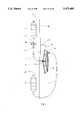
- FIG. 1Adepicts a sectional representation of an in line vent filter useable in accordance with the principles of the present invention
- FIG. 1Bdepicts an isometric view of an in-line vent filter having portions removed therefrom and useable in accordance with the principles of the present invention
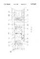
- FIG. 2depicts a schematic sectional representation of a filtration device constructed in accordance with the principles of the present invention
- FIG. 3depicts a schematic representation of the filtration device and in-line vent filter used for filtering blood where a blood supply bag is filled;
- FIG. 4depicts a schematic representation of the filtration device and in-line vent filter used for filtering blood where the blood supply bag is empty;
- FIG. 5depicts an outlet section of an embodiment of the filtration device constructed in accordance with the principles of the present invention whereby a means for placing a first outlet in fluid flow relationship with the second outlet of a second chamber of the device is integrally formed with the outlet section of the device;
- FIG. 6depicts a sectional representation of the alternative embodiment of the filtration device having the outlet section depicted in FIG. 5;
- FIG. 7depicts an isometric view, having portions thereof removed, of the embodiment of the filtration device depicted in FIG. 6;
- FIG. 8depicts an isometric view of the inside surface of the first section of the embodiment of the filtration device depicted in FIG. 7;
- FIG. 9depicts the embodiment of the filtration device depicted in FIG. 7 having the in-line vent filter, tubing, blood supply means and blood collecting means in an operational assembly;
- FIG. 10depicts a cross-sectional view of a lower section of the embodiment of the filtration device depicting one technique for sealing a plurality of filtration elements therein;
- FIG. 11depicts a cross-sectional view of the lower portion of an embodiment of the filtration device depicting an alternative technique for sealing a plurality of filtration elements
- FIG. 12depicts a cross-sectional view of the lower portion of a filtration device constructed in accordance with the principles of the present invention depicting one technique for sealing the outer edges of a plurality of filtration elements;
- FIG. 13depicts a cross-sectional view of the lower portion of a filtration device constructed in accordance with the principles of the present invention depicting an alternative technique for sealing the outer edges of a plurality of filtration elements;
- FIG. 14depicts a schematic representation of yet another embodiment of the filtration device constructed in accordance with the principles of the present invention along with a vent filter blood supply means and blood collecting means.
- the liquid filtration device constructed in accordance with the principles of the present inventionutilizes an air venting means operatively engaged to a fluid filtration means.
- FIG. 2One embodiment of the filtration apparatus constructed in accordance with the principles of the present invention is shown in FIG. 2, and its operation depicted in FIGS. 3 and 4.
- FIG. 1Adepicts a schematic representation of an in line vent filter 15 useable as an air venting means in accordance with the principles of the present invention.
- the automatic in-line vent filterautomatically vents the inlet of the fluid filtration system when fluid stops flowing from feed blood bag 20.
- the in-line vent filter 15automatically stops venting.
- This vent filtermay consist of an inlet section 1, an outlet section 2, and a sterilizing grade hydrophobic filter 3.
- the hydrophobic filterprevents the passage of liquid therethrough, (assuming the liquid is at a pressure less than the bubble point pressure of the filter material) while allowing the passage of air therethrough. Air is capable of passing through the hydrophobic filter even after the filter has been exposed to a liquid.
- the inlet section 1may include vent ports 4 which are in air flow relationship to the outside of the vent filter.
- the hydrophobic filter 3is sealed to the inlet section 1 by seals 5 and 6, which are preferably heat seals.
- seals 5 and 6are preferably heat seals.
- any type of reliable leak proof sealswhich are well known in the art, such as ultrasonic, solvent or adhesive type seals may be used in accordance with the invention.
- the in-line vent filter 15may be a round device and the hydrophobic filter may be shaped as a disc with a hole punched in its center.
- the in-line vent filter 15is not limited to any particular shape and may include more than one hydrophobic filter 3.
- Seal 5should extend around the entire periphery of the center hole of the hydrophobic filter 3 and hence around the entire periphery of a port 7 sealing the hydrophobic filter 3 to the inlet section 1.
- Seal 6seals the hydrophobic filter to the inlet section 1 around the entire outer periphery of the hydrophobic filter 3.
- liquid within the chamber 10may not pass through the hydrophobic filter 3, air may enter vent ports 4 and pass through hydrophobic filter 3.
- the inlet section 1 of the vent filtermay also include a tubing socket 8 into which a length of tubing 14 may be inserted.
- the tubing socket 8is in fluid flow relationship with the port 7 which should be approximately the same diameter as the inside diameter of tubing 14.
- the outlet section 2may be bonded to the inlet section 1 by a seal 9.
- Seal 9should extend around the entire periphery of the vent filter 15 thus forming chamber 10.
- Seal 9is preferably an ultrasonic seal. However, other seals including heat seals, adhesive seals or any other hermetic seal may be used.
- Outlet section 2includes restriction 11 forming an outlet of chamber 10, and tubing socket 12 extending from the restriction 11 into which a length of tubing 13 may be inserted. Restriction 11 is typically a long small diameter port which connects chamber 10 to tubing 13.
- the cross sectioned area of the restrictionshould be less than the cross sectioned area of the inlet to allow fluid flowing therethrough to fill chamber 10 and contact hydrophobic filter 3.
- Liquid to be filteredenters the vent filter 15 via tubing 14 and port 7 and exits via restriction 11 and tubing 13.
- the length and diameter of restriction 11depends upon viscosity of the liquid being filtered and should be sized so that liquid entering the in-line vent filter 15 through port 7 will back up and fill chamber 10.
- the liquid in chamber 10will be at a pressure head greater than atmospheric pressure and below the bubble point pressure of the hydrophobic filter 3. Since a hydrophobic filter can not pass an aqueous solution at a pressure below the bubble point of the hydrophobic filter, fluid will not exit through ports 4. Likewise since the pressure head in chamber 10 is greater than atmospheric pressure air can not enter chamber 10 via ports 4.
- the restriction 11should not restrict the flow of fluid through the liquid filtration device 129 (described below) which may be attached to the opposite end of the tubing 13.
- the pressure head in chamber 10shall decrease to zero enabling air to enter chamber 10 via ports 4 and hydrophobic filter 3 thus draining restriction 11 and tubing 13.
- FIG. 1Bdepicts an in-line vent filter which is similar in structure and operation to the vent filter depicted in FIG. 1A but also contains an inside channel 17 and a plurality of support ribs 18.
- the inside portion of inlet section 1 of the vent filter 15may contain channel 17 which provides a gap between the hydrophobic filter 3 and inlet section 1 which leads to vent ports 4.
- the outlet half 2contains a plurality of support ribs 18 which assist in supporting the hydrophobic filter 3.
- FIG. 2is a schematic representation of the filtration device 129 which is suited for blood filtration and leukocyte and/or other blood component removal therefrom.
- Filtration device 129includes inlet section or half 101 which is bonded to an outlet section or half 102 by a seal 120.
- This seal 120is preferably an ultrasonic seal. However, other seals such as heat seals or adhesive seals or any other hermetic seal may be used.
- Inlet section 101includes tubing socket 113 into which the outlet end of tubing 13 is affixed as well as port 122. The inlet end of tubing 13 is affixed to the outlet of the-vent filter 15.
- Inlet section 101contains side walls 131 extending about the periphery of bottom wall 130. Side walls 131 and bottom wall 130 define chamber 108. Any fluid exiting the vent filter 15 via tubing 13 will enter chamber 108 through port 122.
- Outlet section 102 of the filtration device 129may include a tube 110 affixed thereto which defines a passage 111.
- Tube 110is preferably round and multi-diameter, however, other shapes may suffice.
- Outlet section 102may also include a port 121, port 123, port 124, tubing socket 114 and tubing socket 115.
- Outlet section 102includes a bottom wall 132 and side walls 133 extending about the periphery thereof. Side walls 133 and bottom wall 132 define chamber 109 of outlet half 102.
- a cover 112may be affixed to outlet half 102 by seal 125. Seal 125 is preferably an ultrasonic seal. However, other seals may suffice.
- the cover 112 and multi diameter tube 110define a chamber 111 which is in fluid flow relationship with chamber 109 via port 121.
- a hydrophobic filter 104is sealed to an end of multi diameter tube 110, extending into chamber 108, by peripheral seal 105.
- Peripheral seal 105is preferably a heat seal.
- other types of reliable leak proof sealssuch as ultrasonic or adhesive seals may suffice.
- a hydrophilic filter 106may be sealed to outlet section 102 by peripheral seal 107 to cover port 123. When dry, the hydrophilic filter 106 allows the passage of air therethrough except at peripheral seal 107, which should preferably be a heat seal. However, other types of reliable leak proof seals such as ultrasonic or adhesive seals may suffice. When wet, the hydrophilic filter 106 does not allow the passage of air therethrough unless the air pressure is above the bubble point pressure of the hydrophilic filter 106.
- the hydrophobic filter 104covers the end of tube 110 and, therefore, should be the same shape as the end of tube 110.
- Filtering elements 103which may be leukocyte removing elements for blood filtration, should be shaped to divide the filtration device 129 into chamber 108 and chamber 109.
- the filtration elements 103defines, along with inlet section 101, chamber 108 and, along with outlet section 102, chamber 109.
- Each filtration element 103may have a hole therein which is positioned to enable the hole to align with tube 110 when the filtration elements 103 are placed into the filtration device 129. Therefore, it is preferred that the hole have the same shape and size of the small end of tube 110.
- the filtration elements 103fit into and are contained by a filter element receptacle which is defined by side walls 145 of outlet section 102, and by shelf 147 of outlet section 102 and sealing rib 148 of inlet section 101.
- the filtration device 129 in FIG. 2contains four (4) filtration elements 103.
- the filtration elements 103may include leukocyte removing elements which are known in the art. Depending on the application, the filtration device 129 could be manufactured to accept more or less than four filtration elements 103.
- the outside periphery of the filtration elements 103may be sealed to the filtration device 129 by a pinch seal 119 wherein the outside periphery of the filtration elements 103 is pressed between sealing rib 148 of inlet section 101 and shelf 147 of outlet section 102 creating a seal.
- the filtration elements 103may be sealed to the tube 110 by a pinch seal 126.
- a washer 118which may be press fitted about multi diameter tube 110 forces the filtration elements 103 between washer 118 and the lip 99 of tube 110 to form seal 126.
- washer 118could be ultrasonically welded, heat sealed or sealed with an adhesive to tube 110.
- filtration elements 103could be sealed to the filtration means 129 and multi diameter tube 110 by other reliable sealing techniques.
- a first outlet from the chamber 109is formed by port 124 which is in fluid flow relationship with Tee 127 via siphon tube 116.
- a second outlet from chamber 109is formed by port 123 which is in fluid flow relationship with Tee 127 via tube 128.
- Tee 127is in fluid flow relationship with a fluid or liquid receiving means via tubing 117.
- the tube 128, tee 127 and tube 116function as a means for placing the first outlet formed by port 124 in fluid flow relationship with the second outlet formed by port 123.
- the receiving meanscould be a blood bag or even an open container. However, when using the system for blood filtration, a sterile receiving blood bag should be used.
- FIG. 2illustrates the inlet port 122 near the top of inlet half 101
- port 122may be placed in other locations. Moreover, port 122 need not be located on the vertical center line of inlet half 101. However, port 122 should not be placed adjacent to or directly below hydrophobic filter 104, particularly if the gap between wall 130 of inlet half 101 and hydrophobic filter 104 is small.
- FIG. 3illustrates one embodiment of the apparatus or system in accordance with the present invention including the vent filter 15, the filtration means 129, a feed blood bag 20, a receiving blood bag 21, and all the necessary interconnecting tubing.
- the userwould purchase the system without feed blood bag 20.
- the userwould receive the system sterilized with the inlet end of tubing 14 sealed to maintain system sterility. Therefore, with the exception of ports 4 the system is closed.
- the hydrophobic filter 3 of vent filter 15should be a sterilizing grade filter which is sealed with a leak tight seal to the inlet section 1 of the vent filter 15. Therefore, the inside of the system should remain sterile.
- Feed blood bag 20may be suspended from an appropriate mechanism.
- the filtration means 129may also be suspended from the mechanism or by tubing 13.
- a receiving blood bag 21may be suspended by the mechanism or may rest on a surface such as a bench top or the like.
- bloodwill begin to flow from feed blood bag 20, through tubing 14, through vent filter 15, tubing 13 and finally through port 122 into chamber 108.
- the blood flowis indicated by the solid arrows.
- airwill vent from chamber 108 through the unwetted portions of filtration elements 103 (i.e. through the portion of the filtration elements 103 above the blood level) and through hydrophobic filter 104.
- the air that vents through hydrophobic filter 104will pass through chamber 111 and then through port 121 and finally into chamber 109.
- the air that vents through the unwetted portions of filtration pads 103will pass directly into chamber 109.
- chamber 108will stop venting from chamber 108 through hydrophobic filter 104 and all venting of chamber 108 will occur through the unwetted portions of filtration elements 103 (which in this blood filtration application may include leukocyte removing elements or elements used to remove other blood components). Chamber 108 will continue to fill with blood until all of the air in chamber 108 has been vented and chamber 108 is full of blood.
- leukocyte depleted bloodwill start to pass from the elements 103 into chamber 109.
- This leukocyte depleted blood flow into chamber 109will begin at or near the bottom of chamber 109.
- the surface area of the elements 103is much greater than the surface area of the hydrophilic filter 106, and because the initial flow rate of blood through the elements 103 is high, and because the bubble point pressure of the hydrophilic filter 106 must be greater than pressure head at hydrophilic filter 106 relative to receiving blood bag 21, the following sequence of events will occur.
- the air pressure in chamber 109will start to increase because the flow rate of leukocyte depleted blood entering chamber 109 will be greater than the flow rate of air exiting chamber 109 through hydrophilic filter 106 (because of the necessary maximum pore size of hydrophilic filter 106). This increase in air pressure in chamber 109 will cause blood to flow out of port 124 and into siphon tube 116. The blood level in tube 116 will then rise faster than the blood level in chamber 109.
- the leukocyte depleted blood in tube 116will reach Tee 127 and fill Tee 127, the hydrophilic filter 106 will not be wet by the leukocyte depleted blood on the Tee side of hydrophilic filter 106 if tube 128 is of sufficient length or port 123 is sufficiently small. Assuming that one or both of these conditions is true the leukocyte depleted blood in Tee 127 will exit Tee 127 and then flow down tubing 117 into the receiving blood bag 21. At this point the pressure head at the bottom of chamber 108 relative to the top of the supply bag 20 will be greater than, the relative pressure head at the top of chamber 108.
- the pressure of the air in chamber 109will be above atmospheric pressure and the pressure head in Tee 127 relative to the receiving blood bag 21 will be less than the pressure head at the top of chamber 109 and at the bottom of chamber 109. Hence the pressure in Tee 127 will be lower than the pressure in chamber 109. Therefore air will be sucked from chamber 109 through hydrophilic filter 106, then through port 123, then through tube 128 into Tee 127. At this point there will be a mixed stream of leukocyte depleted blood and air flowing down tubing 117 into receiving blood bag 21. As air is evacuated from chamber 109 the leukocyte depleted blood level in chamber 109 will rise.
- hydrophilic filter 106This process will continue until the level of leukocyte depleted blood in chamber 109 either covers hydrophilic filter 106 or until hydrophilic filter 106 becomes wetted by capillary action. Once the hydrophilic filter 106 is wet it will no longer allow air passage therethrough unless the air pressure exceeds the bubble point pressure of the hydrophilic filter 106.
- the pore size of hydrophilic filter 106should be chosen so that once hydrophilic filter 106 is wet it will not allow air passage therethrough for the duration of the process. To assure that there will be a minimum amount of air trapped at the top of chamber 109 it is preferred that the volume of chamber 109 around hydrophilic filter 106 be kept to a minimum.
- tubing 14, vent filter 15, tubing 13 and chamber 108will be full of unfiltered blood.
- Chamber 109, siphon tube 116, tee 127 and tubing 117will be full of leukocyte depleted blood and receiving blood bag 21 will be partially filled with leukocyte depleted blood with a small air pocket at the top of receiving blood bag 21 due the air that was initially purged from the system.
- the pressure head at the top of chamber 108 relative to the supply bag 20will still be less than the pressure head at the bottom of chamber 108 relative to the supply bag 20.
- the pressure head at the bottom of chamber 109 relative to the supply bagwill be equal to the pressure head at the bottom of chamber 108 less the pressure drop across the leukocyte removing pads 103 and the pressure head in Tee 127 relative to the receiving bag will be slightly greater than previously when the receiving bag began to fill due to the fact that receiving blood bag 21 has begun to fill. Throughout the process the external pressure on feed blood bag 20 and receiving blood bag 21 will be atmospheric.
- Hydrophobic filter 104should be of the minimum surface area necessary to allow drainage of chamber 109 in a reasonable time period. It should also be of the minimum surface area necessary so that a minimum amount of active surface area is removed from filtration elements 103 to allow for tube 110.
- Multi diameter tube 110should be placed as close to the bottom of chamber 108 as other design considerations permit.
- Chamber 109will continue to drain in this manner until the leukocyte depleted blood level reaches the top of port 124. Then the tube 116 will be drained and tubing 117 will drain to the leukocyte depleted blood level at the top of receiving blood bag 21. Tubing 117 should then be sealed close to the receiving blood bag 21 and receiving blood bag 21 along with the short length of sealed tubing 117 may be cut from the rest of the system and is ready for use. The rest of the system (i.e. feed blood bag 20, vent filter 15, fluid filtration means 129, Tee 127 and all remaining tubing should be discarded in a proper manner.
- the air that initially fills the voids in the systemis purged into receiving blood bag 21 when the system is primed with blood.
- the void volumeshould be kept to a minimum.
- the gap between wall 130 of inlet section 101 and hydrophobic filter 104should be kept to a minimum. Therefore, port 122 of inlet section 101 should not be placed adjacent to or directly below hydrophobic filter 104.
- FIGS. 5-9illustrates an alternative embodiment of the filtration device 229 constructed in accordance with the principals of the present invention.
- This embodimentmay be easily manufactured using disposable injection molded plastic components.
- the filtration device 229may be designed so that the user can easily hang all the system components from a hanging means such as a pole with hooks to allow for gravity feed of the fluids, such as blood, to be filtered.
- This embodimentoperates in the same manner as the embodiment previously discussed.
- the means for placing the first outlet, formed by port 124 of chamber 109, in fluid flow relationship with the second outlet, formed by port 123 of chamber 109,is integrally formed to outlet section 202.
- a conduit 251is formed by a ridge 249 extending from the outlet section 202 and an outlet cover 212 which is sealed to the ridge 249. Ridge 249 and outlet cover 212 are sealed to prevent fluid flowing within conduit 251 from leaking therefrom.
- An interior ridge 250extends from the outlet section 202 but within conduit 251. Raised ridge 250 also contacts outlet cover 212 to form a chamber 111 which is isolated from conduit 251 so that fluid within conduit 251 cannot enter chamber 111.
- chamber 111Within chamber 111 is located an end of the interior of tube 110 which passes through filtering elements 103 (FIG. 6).
- port 121places chamber 111 in fluid flow relationship with chamber 109. Accordingly, chamber 109 is placed in fluid flow relationship with chamber 108 by the interior of tube 110, chamber 111, and port 121, which are all in fluid flow relationship with each other.
- conduit 251Within conduit 251 is the first outlet of chamber 109 formed by port 124 and the second outlet of chamber 109 formed by port 123. Both port 123 and port 124, constitute passages which lead into chamber 109 placing conduit 251 in fluid flow relationship with the chamber 109.
- a hanging means 244may be oriented to allow the housing formed by the first section 201 and second section 202 to be gravity hung. In the hanging position, the second outlet formed by port 123 is located above first outlet formed by port 124 for improved operation of the filtration device.
- the inlet section 201is engaged with outlet section 202 to form a housing.
- the edges of the filtration elements 103are located between the inlet section 201 and outlet section 202.
- Seal 120is used to seal the inlet section 201 to the outlet section 202.
- Inlet port 122leads to chamber 108 which is in fluid flow relationship with tube 110.
- Hydrophobic filter 104is located at one end of tube 110 to prevent liquid to be filtered, such as blood, from passing therethrough.
- a seal 105seals the hydrophobic filter to the tube 110.
- the washer 118is placed around tube 110 so that filtration elements 103 are located between the washer 118 and a lip 299.
- Hydrophilic filter 106is preferably located over port 123 to prevent air from within the chamber 109 from flowing through the port 123 when hydrophilic filter 106 is wet.
- the hydrophilic filtermay be recessed within a well 207.
- a heat sealis used to seal the hydrophilic filter to the outlet section 202.
- Port 123is in fluid flow relationship with conduit 251.
- a nipple 260may be formed around port 123 for allowing filtered fluid, such as blood, from flowing therethrough into a collection tube 117 and eventually into a collection bag 221.
- first section 101may require a recessed area 260 to allow tube 110 to protrude into chamber 108.
- FIG. 7depicts a sectional view of the aforementioned embodiment of the filtration device 229.
- a plurality of ribs 242are located on the inside surface of second section 202 .
- the ribs 242serve to stabilize the position of filtration elements 103 while allowing liquid such as blood to be filtered to flow through chamber 109.
- the ribsprevent the pressure exerted within chamber 108 from deforming the filtration elements 103.
- FIG. 8depicts the inside surface of first section 201.
- Recess 260contains a ridge 261 located on one or more edges thereof and extending from the inside surface 230 of the first section. As shown in FIG. 6, ridge 261 contacts washer 118 to maintain a force against the portion of filtration elements 103 between the washer 118 and lip 299.
- the fluid filtration device when used to filter bloodmay be used by placing a blood supply bag 220 in fluid flow relationship with an in-line vent filter 15. Blood flowing through the vent filter is carried by a conduit 13 to filtration device 229 via inlet nipple 113.
- a collection tube 117is connected to an outlet nipple 260, at one end, and at the other end to a blood collecting bag 221. The filtration of blood occurs without the need for manually opening and closing vents or for moving the blood collecting bag to different heights relative to the blood supply bag or housing 229.
- FIG. 10is an exploded view of the lower part of the filtration device 229 depicted in FIG. 6 for the purposes of depicting sealing techniques useable in connection with the present invention.
- the fluid filtration device 229contains four filtration elements 103. However, more or less than four filtration elements 103 may be used depending on the application.
- Each filtration element 103may provide a logarithmic reduction of leukocytes from the blood that passes through that layer. For example, if unfiltered blood initially contains 1,000 leukocytes/ml, it will contain 100 leukocytes/ml after passing through one filtration element 103. Hence four leukocyte filtration elements 103 should give four orders of logarithmic reduction of leukocytes and/or other blood components.
- FIG. 10is an exploded view of the lower part of the filtration device 229 depicted in FIG. 6 for the purposes of depicting sealing techniques useable in connection with the present invention.
- the fluid filtration device 229contains four filtration elements 103. However, more or less than four
- Bloodmay bypass filtration through each of the elements.
- Blood flowmay start in chamber 108 and follows the shortest path from chamber 108 through the first filtration element into gap 284 between tube 110 and the edge of the filtration elements 103 and through the last filtration elements 103 into chamber 109.
- FIG. 11A preferred solution to the above mentioned bypass problem is illustrated in FIG. 11.
- flanged washers 285, 286, 287 and 288independently seal each layer of the leukocyte removing elements 103 around tube 110.
- Each flanged washershould be sized to contact either the washer stacked thereupon, surface 255, or ridge 261 depending upon its position.
- preferably flanged washers 285, 286, 287, and 288,are press fit around tube 110.
- other reliable sealing techniquescould be used to seal the flanged washers to tube 254.
- each interior flanged washercould be sealed to the adjoining washers.
- the flanged washer contacting ridge 261may be sealed thereto and/or the flange washer contacting surface 255 may be sealed to surface 255. Also, it may be possible to use a number of flanged washers which are less than the number of filtration elements. If a press fit is used between the flanged washers and tube 254, then the flanged washers and tube 254 may be made of dissimilar materials which are preferably radiation sterilizable. The flange of the flanged washers should be made as thin as practical so as to minimize wrinkling of the filtration elements 103. Ridge 261 of inlet half 201 prevents the flanged washers from rising on tube 254 once inlet half 201 is sealed to outlet half 202.
- FIG. 12depicts the lower portion of the embodiment of the filtration device 229 depicted in FIG. 11 using an alternative means for sealing the edges of filtration elements 103.
- Flanged rings 271, 272,273, 274are placed over the edges of each filtration element 103.
- Each flanged ringmay be sealed to the second section 202, or each flanged ring may be sealed to its adjacent flanged ring and the lower flanged ring 274 sealed to second section 202.
- each or some of the flanged rings 271, 272, 273, 274may be press fit against side wall 245 of second section 202.
- Each flanged ringshould extend throughout the outer edge of the filtration elements. Also, it may be possible to use a number of flanged rings which is less than the number of filtration elements.
- FIG. 13depicts an alternative technique for sealing the edges of filtration elements 103.
- the edge 276 of the bottom filtration elementis bonded to second section 202, preferably by a heat seal which extends around the entire periphery of the filtration element 103.
- the heat sealwill compress the fibers at the edges 276, 277, 278, 279, of the filtration element which will effectively reduce the filtration capability of the elements at the interface between the compressed and noncompressed region.
- layers of polyethylene film 98may be placed between each layer of the filtration elements 103 prior to sealing the edges of each layer 276, 277, 278, 279 to one another. The polyethylene film layers 98 prevent blood from filtering through the interface regions affected by the heat sealing.
- thermoplastic filmsmay be used in lieu of a polyethylene film 98.
- the film layersshould extend around the entire periphery of filtration elements 103.
- the edge 276 of the lower filtration elementmay be sealed to second section 202 and the other edges 277, 278, 279 of the filtration elements may be sealed to one another.
- other patterns and techniques for sealing the edges 276, 277, 278, 279 to one another or to the second section 202may be used.
- FIG. 14illustrates yet another embodiment of the invention.
- This filtration devicedoes not contain a second outlet from the second chamber 109 or a means for placing the first outlet 124 in fluid flow relationship to a second outlet.
- Tubing 168 looping around the back of filtration device 129acts a means for placing the first chamber 108 in fluid flow relationship with the second chamber.
- a sterile connectionwould be made between tubing 14 and feed blood bag 20.
- the system componentswould then be suspended as depicted in FIG. 14. Blood would flow from tubing 13 through port 122 into chamber 108 of inlet half 101. Chamber 108 will fill from the bottom up until chamber 108 is full.
- tubing socket 113 and port 122can be located anywhere on inlet half 101.
- Filter 104is a hydrophobic filter which prevents blood from flowing therethrough.
- filtration elements 103will begin to wet from the bottom up.
- the air in chamber 108will vent through the non wet portions of filtration elements 103 into chamber 109. This air will exit from chamber 109 into receiving blood bag 21 through port 124 and tubing 117.
- As filtration elements 103 wet, the air that was in these filtration elementswill also vent into chamber 109 and then into receiving blood bag 21 through port 124 and tubing 117. Blood will begin to flow through filtration elements 103 from the bottom up.
- both blood and airwill be passing from filtration elements 103 into chamber 109 of outlet section 102 and a mixed stream of blood and air will pass through port 124 and tubing 117 into receiving blood bag 21. This process will continue until filtration elements 103 are completely wet with blood. The blood level in chamber 109 will then rise to a level just above the level of tubing 117 as depicted in FIG. 14. At this point tubing 117 will be full of blood (i.e., no air) and air will cease to flow into receiving blood bag 21.
- hydrophobic filter 106should be placed at the bottom of chamber 108 and hydrophobic filter 106 should be of small enough pore size to give the necessary delay (i.e., to allow chamber 108 to finish draining before enough air passes through hydrophobic filter 106 into chamber 109 and causes chamber 109 to drain). If hydrophobic filter 106, tubing socket 167 and port 194 are located at a higher location on inlet half 101 filtration device 129 will still filter in the same manner, but chamber 108 will not completely drain at the end of the filtration process.
Landscapes
- Health & Medical Sciences (AREA)
- Engineering & Computer Science (AREA)
- Heart & Thoracic Surgery (AREA)
- Vascular Medicine (AREA)
- Chemical Kinetics & Catalysis (AREA)
- Chemical & Material Sciences (AREA)
- Water Supply & Treatment (AREA)
- Anesthesiology (AREA)
- Cardiology (AREA)
- Biomedical Technology (AREA)
- Hematology (AREA)
- Life Sciences & Earth Sciences (AREA)
- Animal Behavior & Ethology (AREA)
- General Health & Medical Sciences (AREA)
- Public Health (AREA)
- Veterinary Medicine (AREA)
- External Artificial Organs (AREA)
- Infusion, Injection, And Reservoir Apparatuses (AREA)
Abstract
Description
Claims (30)
Priority Applications (13)
| Application Number | Priority Date | Filing Date | Title |
|---|---|---|---|
| US08/209,523US5472605A (en) | 1994-03-10 | 1994-03-10 | Filtration device useable for removal of leukocytes and other blood components |
| DK95911779.7TDK0749345T4 (en) | 1994-03-10 | 1995-02-15 | Filtration Device for Leukocyte Removal |
| AT95911779TATE230291T1 (en) | 1994-03-10 | 1995-02-15 | FILTRATION DEVICE FOR REMOVING LEUKOCYTES |
| AU19219/95AAU696270B2 (en) | 1994-03-10 | 1995-02-15 | A filtration device usable for removal of leukocytes and other blood components |
| CN95192986ACN1148349A (en) | 1994-03-10 | 1995-02-15 | Filtration device for removing leukocytes |
| EP95911779AEP0749345B2 (en) | 1994-03-10 | 1995-02-15 | A filtration device for removal of leukocytes |
| DE69529278TDE69529278T3 (en) | 1994-03-10 | 1995-02-15 | FILTRATION DEVICE FOR REMOVING LEUKOCYTES |
| PCT/US1995/002002WO1995024255A1 (en) | 1994-03-10 | 1995-02-15 | A filtration device for removal of leukocytes |
| US08/680,674US5902490A (en) | 1994-03-10 | 1996-07-16 | Filtration method and device useable for removal of leukocytes and other blood components |
| US08/903,271US5779902A (en) | 1994-03-10 | 1997-07-25 | In-line vent filter for automatically draining a biological liquid filtration device |
| US09/119,292US6015500A (en) | 1994-03-10 | 1998-07-20 | Filtration device useable for removal of leukocytes and other blood components |
| US09/434,182US6251292B1 (en) | 1994-03-10 | 1999-11-04 | Method of preventing air from becoming entrapped within a filtration device |
| US09/467,192US6274055B1 (en) | 1994-03-10 | 1999-12-20 | In-line liquid filtration device useable for blood, blood products or the like |
Applications Claiming Priority (1)
| Application Number | Priority Date | Filing Date | Title |
|---|---|---|---|
| US08/209,523US5472605A (en) | 1994-03-10 | 1994-03-10 | Filtration device useable for removal of leukocytes and other blood components |
Related Child Applications (1)
| Application Number | Title | Priority Date | Filing Date |
|---|---|---|---|
| US44936295ADivision | 1994-03-10 | 1995-05-24 |
Publications (1)
| Publication Number | Publication Date |
|---|---|
| US5472605Atrue US5472605A (en) | 1995-12-05 |
Family
ID=22779089
Family Applications (4)
| Application Number | Title | Priority Date | Filing Date |
|---|---|---|---|
| US08/209,523Expired - LifetimeUS5472605A (en) | 1994-03-10 | 1994-03-10 | Filtration device useable for removal of leukocytes and other blood components |
| US08/680,674Expired - LifetimeUS5902490A (en) | 1994-03-10 | 1996-07-16 | Filtration method and device useable for removal of leukocytes and other blood components |
| US08/903,271Expired - LifetimeUS5779902A (en) | 1994-03-10 | 1997-07-25 | In-line vent filter for automatically draining a biological liquid filtration device |
| US09/119,292Expired - LifetimeUS6015500A (en) | 1994-03-10 | 1998-07-20 | Filtration device useable for removal of leukocytes and other blood components |
Family Applications After (3)
| Application Number | Title | Priority Date | Filing Date |
|---|---|---|---|
| US08/680,674Expired - LifetimeUS5902490A (en) | 1994-03-10 | 1996-07-16 | Filtration method and device useable for removal of leukocytes and other blood components |
| US08/903,271Expired - LifetimeUS5779902A (en) | 1994-03-10 | 1997-07-25 | In-line vent filter for automatically draining a biological liquid filtration device |
| US09/119,292Expired - LifetimeUS6015500A (en) | 1994-03-10 | 1998-07-20 | Filtration device useable for removal of leukocytes and other blood components |
Country Status (8)
| Country | Link |
|---|---|
| US (4) | US5472605A (en) |
| EP (1) | EP0749345B2 (en) |
| CN (1) | CN1148349A (en) |
| AT (1) | ATE230291T1 (en) |
| AU (1) | AU696270B2 (en) |
| DE (1) | DE69529278T3 (en) |
| DK (1) | DK0749345T4 (en) |
| WO (1) | WO1995024255A1 (en) |
Cited By (50)
| Publication number | Priority date | Publication date | Assignee | Title |
|---|---|---|---|---|
| US5863436A (en)* | 1990-05-24 | 1999-01-26 | Pall Corporation | Venting system |
| US5871693A (en)* | 1996-06-07 | 1999-02-16 | Minnesota Mining And Manufacturing Company | Modular blood treatment cartridge |
| US6010633A (en)* | 1997-03-06 | 2000-01-04 | Hemasure Inc. | Method of preventing air from becoming entrapped within a filtration device |
| US6086770A (en)* | 1990-05-24 | 2000-07-11 | Pall Corporation | Venting system |
| WO2001019429A1 (en)* | 1999-09-17 | 2001-03-22 | Nuvasive, Inc. | Bone slurry recovery |
| US6231770B1 (en) | 1996-07-09 | 2001-05-15 | Pall Corporation | Multiple element filter and method of using therefor |
| US6251292B1 (en)* | 1994-03-10 | 2001-06-26 | Hemasure, Inc. | Method of preventing air from becoming entrapped within a filtration device |
| WO2001076721A1 (en) | 2000-04-06 | 2001-10-18 | Hemasure Inc. | Gravity driven liquid filtration system and method for filtering biological liquid |
| WO2002011855A1 (en)* | 2000-08-04 | 2002-02-14 | Pheresis Research Limited | A filter |
| US20030111403A1 (en)* | 2001-11-30 | 2003-06-19 | Hemerus Medical, Llc | Filter media surface modification for enhanced sealing and apparatus utilizing the same |
| US6601710B2 (en) | 1999-04-20 | 2003-08-05 | Baxter International Inc. | Filter assembly having a flexible housing |
| US20030209479A1 (en)* | 2000-07-10 | 2003-11-13 | Lynn Daniel R | Blood filters, blood collection and processing systems, and methods therefore |
| US6896753B2 (en)* | 2001-10-24 | 2005-05-24 | Honeywell International, Inc. | Method of making a fluid filter, and filter which is a product thereof |
| US20050234429A1 (en)* | 2004-04-17 | 2005-10-20 | Marco Geyer | Drainage chamber for collecting body fluids, in particular liquor |
| US6964646B1 (en)* | 1999-08-12 | 2005-11-15 | Fresenius Hemocare Gmbh | Device and method for autologous blood transfusion |
| US20060108272A1 (en)* | 2003-09-12 | 2006-05-25 | Scott Ariagno | Flow-through removal device and system using such device |
| US7153425B2 (en)* | 1999-09-17 | 2006-12-26 | Entegris, Inc. | Process and filter for filtering a slurry |
| US7247245B1 (en)* | 1999-12-02 | 2007-07-24 | Entegris, Inc. | Filtration cartridge and process for filtering a slurry |
| US20070204924A1 (en)* | 2004-10-28 | 2007-09-06 | Pall Corporation | Valve |
| US20100044299A1 (en)* | 2006-09-22 | 2010-02-25 | Duval Neal M | Method of preventing filter media cracking when compressing two or more filter media layers |
| US7686779B1 (en) | 1999-10-01 | 2010-03-30 | Caridian BCT, Inc | Extracorporeal blood processing methods and apparatus |
| US20100143879A1 (en)* | 2007-03-02 | 2010-06-10 | Stephen Curran | Apparatus and method for filter cleaning by ultrasound, backwashing and filter movement during the filtration of biological samples |
| US20100181251A1 (en)* | 2007-06-25 | 2010-07-22 | Benno Alspektor | Bidirectional Transfer of an Aliquot of Fluid Between Compartments |
| WO2010090418A3 (en)* | 2009-02-09 | 2010-12-02 | (주)이화프레지니우스카비 | Filter device and syringe incorporating same |
| WO2012003122A1 (en) | 2010-07-01 | 2012-01-05 | Cardiac Pacemakers, Inc. | Rhythm correlation diagnostic measurement |
| US20120045424A1 (en)* | 2009-04-21 | 2012-02-23 | Aaron Esteron | Assembly, device kit and method for preparing platelet-rich plasma (prp) |
| US8440085B2 (en)* | 2011-06-06 | 2013-05-14 | Pall Corporation | Plasma separation |
| US8997998B2 (en) | 2008-07-25 | 2015-04-07 | Smith & Nephew Plc | Controller for an acoustic standing wave generation device in order to prevent clogging of a filter |
| US20160361486A1 (en)* | 2014-02-26 | 2016-12-15 | Fresenius Medical Care Deutschland Gmbh | Medical fluid cassette and medical hose set with a medical fluid cassette |
| US9782707B2 (en) | 2014-03-24 | 2017-10-10 | Fenwal, Inc. | Biological fluid filters having flexible walls and methods for making such filters |
| US9796166B2 (en) | 2014-03-24 | 2017-10-24 | Fenwal, Inc. | Flexible biological fluid filters |
| US9968738B2 (en) | 2014-03-24 | 2018-05-15 | Fenwal, Inc. | Biological fluid filters with molded frame and methods for making such filters |
| US10159778B2 (en) | 2014-03-24 | 2018-12-25 | Fenwal, Inc. | Biological fluid filters having flexible walls and methods for making such filters |
| US10376627B2 (en) | 2014-03-24 | 2019-08-13 | Fenwal, Inc. | Flexible biological fluid filters |
| CN110652776A (en)* | 2018-06-28 | 2020-01-07 | 艾欧史密斯(中国)热水器有限公司 | Filter element |
| CN111773781A (en)* | 2020-09-04 | 2020-10-16 | 天津中新智冠信息技术有限公司 | Control method and device of filter press material supplementing system, control cabinet and storage medium |
| US10912506B2 (en) | 2012-05-30 | 2021-02-09 | Magnolia Medical Technologies, Inc. | Fluid diversion mechanism for bodily-fluid sampling |
| US11076787B2 (en) | 2017-09-12 | 2021-08-03 | Magnolia Medical Technologies, Inc. | Fluid control devices and methods of using the same |
| US20220008664A1 (en)* | 2018-10-19 | 2022-01-13 | Yong Hyun Kim | Air filter for medicinal liquid injection and medicinal liquid injection apparatus including the same |
| US11234626B2 (en) | 2015-06-12 | 2022-02-01 | Magnolia Medical Technologies, Inc. | Devices and methods for syringe-based fluid transfer for bodily-fluid sampling |
| US11273245B2 (en)* | 2002-07-19 | 2022-03-15 | Baxter International Inc. | Dialysis system having a vented disposable dialysis fluid carrying member |
| US11311218B2 (en) | 2012-11-30 | 2022-04-26 | Magnolia Medical Technologies, Inc. | Syringe-based fluid diversion mechanism for bodily fluid sampling |
| CN114459871A (en)* | 2022-02-25 | 2022-05-10 | 武汉兰丁云医学检验实验室有限公司 | Sealed sample collecting and filtering device |
| US11395612B2 (en) | 2012-05-30 | 2022-07-26 | Magnolia Medical Technologies, Inc. | Fluid diversion mechanism for bodily-fluid sampling |
| US11419531B2 (en) | 2017-12-07 | 2022-08-23 | Magnolia Medical Technologies, Inc. | Fluid control devices and methods of using the same |
| US11786155B2 (en) | 2019-02-08 | 2023-10-17 | Magnolia Medical Technologies, Inc. | Devices and methods for bodily fluid collection and distribution |
| US11857321B2 (en) | 2019-03-11 | 2024-01-02 | Magnolia Medical Technologies, Inc. | Fluid control devices and methods of using the same |
| US11890452B2 (en) | 2012-10-11 | 2024-02-06 | Magnolia Medical Technologies, Inc. | Systems and methods for delivering a fluid to a patient with reduced contamination |
| US12083234B2 (en) | 2015-09-03 | 2024-09-10 | Magnolia Medical Technologies, Inc. | Apparatus and methods for maintaining sterility of a specimen container |
| US12172108B2 (en) | 2018-08-16 | 2024-12-24 | Emd Millipore Corporation | Closed bioprocessing device |
Families Citing this family (30)
| Publication number | Priority date | Publication date | Assignee | Title |
|---|---|---|---|---|
| GB9420390D0 (en)* | 1994-10-10 | 1994-11-23 | Nycomed Salutar Inc | Liposomal agents |
| DE19750062A1 (en)* | 1997-11-12 | 1999-05-20 | Jostra Medizintechnik Ag | Device for the filtration and degassing of body fluids, especially blood |
| US7189365B1 (en)* | 1999-03-04 | 2007-03-13 | Riken | Liquid treating equipment including a storage vessel and a discharge vessel |
| US7651474B2 (en) | 1999-10-01 | 2010-01-26 | Caridianbct, Inc. | Method and apparatus for leukoreduction of red blood cells |
| US6386424B1 (en)* | 2000-11-01 | 2002-05-14 | George M. Goettl | Apparatus for making roof flashing units and method of making the units |
| WO2002043841A2 (en)* | 2000-12-01 | 2002-06-06 | Millipore Corporation | Chemical process system with multi-functional barrier filter |
| EP2277574A1 (en)* | 2000-12-21 | 2011-01-26 | Hemerus Medical, LLC | Biological fluid filter |
| JP2002191905A (en)* | 2000-12-28 | 2002-07-10 | Nipro Corp | Air trap for liquid circulating circuit |
| EP1586339B1 (en)* | 2001-04-13 | 2010-09-08 | Asahi Kasei Medical Co., Ltd. | Liquid filtering method |
| EP2208502B1 (en)* | 2001-12-10 | 2019-05-08 | Terumo BCT, Inc. | Disposable assembly for an apheresis system |
| DE20120897U1 (en)* | 2001-12-28 | 2003-05-08 | IWS Ingenieurgesellschaft Weiner & Schröter mbH,, 47475 Kamp-Lintfort | Protective door for driver's cabins, especially for commercial vehicles |
| US6988497B2 (en)* | 2002-09-18 | 2006-01-24 | Medex Cardio-Pulmonary, Inc. | Apparatus for equalizing air pressure in air respiratory system |
| US20040178162A1 (en)* | 2003-03-14 | 2004-09-16 | Dorothea Zucker-Franklin | Devices and methods for removal of leukocytes from breast milk |
| US7854845B2 (en)* | 2003-09-05 | 2010-12-21 | Hemerus Medical Llc | Biological fluid filtration apparatus |
| US20060226086A1 (en)* | 2005-04-08 | 2006-10-12 | Robinson Thomas C | Centrifuge for blood processing systems |
| US20080223798A1 (en)* | 2005-08-05 | 2008-09-18 | Pall Corporation | Apparatus and System For Displacing Gas in a Biological Fluid Processing System |
| CA2620230A1 (en)* | 2005-10-05 | 2007-04-12 | Gambro Bct, Inc. | Method and apparatus for leukoreduction of red blood cells |
| CN101352622B (en)* | 2008-09-17 | 2010-11-10 | 西安交通大学 | Blood separating device and separating method for filtering leucocyte |
| EP2229970B1 (en) | 2009-03-16 | 2012-06-06 | F. Hoffmann-La Roche AG | Bubble trap system for an infusion pump device |
| ITRE20090087A1 (en)* | 2009-09-08 | 2011-03-09 | Ufi Filters Spa | DEVICE FOR THE REDUCTION OF AIR BUBBLES DIMENSIONS IN ENGINE FUEL DIESEL |
| JP5739699B2 (en) | 2010-06-16 | 2015-06-24 | 日東電工株式会社 | Waterproof ventilation filter and its use |
| KR20170120211A (en) | 2010-06-16 | 2017-10-30 | 닛토덴코 가부시키가이샤 | Waterproof breathable filter and use thereof |
| TWM420333U (en)* | 2011-07-01 | 2012-01-11 | Avita Corp | Body fluid collecting apparatus |
| US10927347B2 (en)* | 2015-05-15 | 2021-02-23 | Black Tie Medical Inc. | Device and method for breaking down and sizing harvested fat |
| FR3043918B1 (en)* | 2015-11-20 | 2018-01-05 | Maco Pharma | RIGID FILTRATION UNIT COMPRISING COMPRESSION PROJECTIONS |
| FR3077987A1 (en)* | 2018-02-22 | 2019-08-23 | Etablissement Francais Du Sang | PLATE AND METHOD FOR HUNTING AIR FROM A TRANSFUSION POUCH |
| EP3836882B1 (en) | 2018-08-17 | 2025-03-19 | Saint-Gobain Performance Plastics Corporation | System and method for storing pharmaceuticals or biological media |
| EP3682961A1 (en)* | 2019-01-16 | 2020-07-22 | Kyongjae Ham | Drain filter with air passage |
| KR20200089073A (en) | 2019-01-16 | 2020-07-24 | 함경재 | The filter with an air passage |
| WO2021096706A1 (en) | 2019-11-12 | 2021-05-20 | Fresenius Medical Care Deutschland Gmbh | Blood treatment systems |
Citations (18)
| Publication number | Priority date | Publication date | Assignee | Title |
|---|---|---|---|---|
| US3593854A (en)* | 1969-12-05 | 1971-07-20 | Roy Laver Swank | Blood treating and filtering apparatus |
| US3892236A (en)* | 1973-04-02 | 1975-07-01 | Isaac Djerassi | Apparatus for filtration-leukopheresis for separation and concentration of human granulocytes |
| US4294594A (en)* | 1979-10-02 | 1981-10-13 | United States Surgical Corporation | Self-contained filter assembly for removing air, particles and bacteria from a solution |
| US4416777A (en)* | 1979-10-09 | 1983-11-22 | Asahi Kasei Kogyo Kabushiki Kaisha | Separation of leukocytes or lymphocytes from leukocyte-containing suspension |
| US4416050A (en)* | 1981-09-24 | 1983-11-22 | Rockwell International Corporation | Method of fabrication of dielectrically isolated CMOS devices |
| US4525182A (en)* | 1983-08-29 | 1985-06-25 | Millipore Corporation | I.V. Filter apparatus |
| US4631050A (en)* | 1985-09-24 | 1986-12-23 | Reed Charles C | Autotransfusion system and method |
| US4675383A (en)* | 1983-11-15 | 1987-06-23 | The Salk Institute For Biological Studies | Purification of T-cell growth factor |
| US4880548A (en)* | 1988-02-17 | 1989-11-14 | Pall Corporation | Device and method for separating leucocytes from platelet concentrate |
| US4906260A (en)* | 1987-08-03 | 1990-03-06 | Gelman Sciences, Inc. | Self-priming intravenous filter |
| US4936998A (en)* | 1986-03-28 | 1990-06-26 | Asahi Medical Co., Ltd. | Filter medium for selectively removing leucocytes |
| US4943287A (en)* | 1989-07-17 | 1990-07-24 | Miles Inc. | Red blood cell storage system |
| EP0406485A1 (en)* | 1989-07-03 | 1991-01-09 | NPBI Nederlands Produktielaboratorium voor Bloedtransfusieapparatuur en Infusievloeistoffen B.V. | A method for the removal of leukocytes from a leukocyte-containing suspension and filter unit for use with the method |
| US4997577A (en)* | 1989-12-20 | 1991-03-05 | Baxter International Inc. | Systems and methods for removing undesired matter from blood cells |
| US5002054A (en)* | 1987-02-25 | 1991-03-26 | Ash Medical Systems, Inc. | Interstitial filtration and collection device and method for long-term monitoring of physiological constituents of the body |
| US5092996A (en)* | 1991-02-19 | 1992-03-03 | Miles Inc. | Blood filtering system |
| EP0500472A2 (en)* | 1991-02-22 | 1992-08-26 | Terumo Kabushiki Kaisha | Leukocyte-removing filter and leukocyte-removing apparatus furnished therewith |
| US5258127A (en)* | 1990-07-27 | 1993-11-02 | Pall Corporation | Leucocyte depleting filter device and method of use |
Family Cites Families (31)
| Publication number | Priority date | Publication date | Assignee | Title |
|---|---|---|---|---|
| US1844342A (en)* | 1930-04-21 | 1932-02-09 | Berman Phoebus | Bottle nozzle |
| US3523408A (en)* | 1968-04-02 | 1970-08-11 | Pall Corp | Gas separator |
| US3631654A (en)* | 1968-10-03 | 1972-01-04 | Pall Corp | Gas purge device |
| US3803810A (en)* | 1972-05-01 | 1974-04-16 | Pall Corp | Liquid-gas separator and filter |
| US3881640A (en)* | 1973-12-12 | 1975-05-06 | Terrance O Noble | Apparatus for measuring liquid in the reconstitution of antibiotics |
| US3967620A (en)* | 1974-09-10 | 1976-07-06 | United States Surgical Corporation | Volume limiting chamber |
| US4126558A (en)* | 1975-01-31 | 1978-11-21 | Johnson & Johnson | Blood filtration unit with manual vent means |
| US4326957A (en)* | 1978-07-21 | 1982-04-27 | Pall Corporation | Vented filter spigot for intravenous liquid administration apparatus |
| US4276170A (en)* | 1978-08-16 | 1981-06-30 | Critikon, Inc. | Vented flexible filtration device for use in administering parenteral liquids |
| US4341538A (en)* | 1978-08-18 | 1982-07-27 | Gelman Instrument Company | Intravenous filter |
| US4298358A (en)* | 1979-01-11 | 1981-11-03 | Baxter Travenol Laboratories, Inc. | Gas separating and venting filter |
| US4228798A (en)* | 1979-05-01 | 1980-10-21 | Deaton David W | Suction receptacle with hygroscopic filter |
| FR2456538A2 (en)* | 1979-05-17 | 1980-12-12 | Boeuf Lola Le | FILTRATION DEVICE |
| US4515606A (en)* | 1981-03-19 | 1985-05-07 | Brunswick Corporation | Gas separating and venting filter |
| US4568366A (en)* | 1983-08-30 | 1986-02-04 | Baxter Laboratories, Inc. | In-line filter |
| US4561868A (en)* | 1984-07-02 | 1985-12-31 | Von Reis Charles | Canister filter assembly |
| US4826494A (en)* | 1984-11-09 | 1989-05-02 | Stryker Corporation | Vacuum wound drainage system |
| JPS62243561A (en)* | 1986-04-15 | 1987-10-24 | 旭メデイカル株式会社 | Leucocyte removing filter device |
| DE3624363C2 (en)* | 1986-07-18 | 1995-06-08 | Akzo Gmbh | Device for separating gas bubbles from infusion liquids or liquids from the human body |
| DE3832028A1 (en)* | 1988-09-21 | 1990-03-22 | Minh Bach Dr Ing Dr Med Quang | DEVICE FOR VENTING LIQUIDS FLOWING IN MEDICAL LIQUID SYSTEMS |
| US5126054A (en)* | 1990-05-24 | 1992-06-30 | Pall Corporation | Venting means |
| US5156602A (en)* | 1990-09-05 | 1992-10-20 | Stryker Corporation | Hydrophobic filter protector for wound drainage system |
| US5536413A (en)* | 1990-12-03 | 1996-07-16 | Pall Corporation | Method for treating a parenteral emulsion-containing medicament fluid |
| US5252222A (en)* | 1990-12-03 | 1993-10-12 | Pall Corporation | Filter for parenteral systems and method of using thereof |
| CA2072378C (en)* | 1991-11-21 | 2000-12-26 | Vlado Ivan Matkovich | System for processing separate containers of biological fluid |
| US5234585A (en)* | 1991-12-19 | 1993-08-10 | Zuk, Incorporated | Vacuum filtration device |
| CA2083075A1 (en)* | 1992-06-10 | 1993-12-11 | Vlado I. Matkovich | System for treating transition zone material |
| DE4321927C2 (en)* | 1993-07-01 | 1998-07-09 | Sartorius Gmbh | Filter unit with degassing device |
| US5439587A (en)* | 1993-07-27 | 1995-08-08 | Millipore Corporation | Self priming filter apparatus |
| US5437655A (en)* | 1993-09-03 | 1995-08-01 | B. Braun Medical Inc. | Air inlet filter for burette top |
| US5545339A (en)* | 1994-02-25 | 1996-08-13 | Pall Corporation | Method for processing biological fluid and treating separated component |
- 1994
- 1994-03-10USUS08/209,523patent/US5472605A/ennot_activeExpired - Lifetime
- 1995
- 1995-02-15CNCN95192986Apatent/CN1148349A/enactivePending
- 1995-02-15EPEP95911779Apatent/EP0749345B2/ennot_activeExpired - Lifetime
- 1995-02-15DKDK95911779.7Tpatent/DK0749345T4/enactive
- 1995-02-15AUAU19219/95Apatent/AU696270B2/ennot_activeCeased
- 1995-02-15ATAT95911779Tpatent/ATE230291T1/enactive
- 1995-02-15DEDE69529278Tpatent/DE69529278T3/ennot_activeExpired - Lifetime
- 1995-02-15WOPCT/US1995/002002patent/WO1995024255A1/enactiveIP Right Grant
- 1996
- 1996-07-16USUS08/680,674patent/US5902490A/ennot_activeExpired - Lifetime
- 1997
- 1997-07-25USUS08/903,271patent/US5779902A/ennot_activeExpired - Lifetime
- 1998
- 1998-07-20USUS09/119,292patent/US6015500A/ennot_activeExpired - Lifetime
Patent Citations (18)
| Publication number | Priority date | Publication date | Assignee | Title |
|---|---|---|---|---|
| US3593854A (en)* | 1969-12-05 | 1971-07-20 | Roy Laver Swank | Blood treating and filtering apparatus |
| US3892236A (en)* | 1973-04-02 | 1975-07-01 | Isaac Djerassi | Apparatus for filtration-leukopheresis for separation and concentration of human granulocytes |
| US4294594A (en)* | 1979-10-02 | 1981-10-13 | United States Surgical Corporation | Self-contained filter assembly for removing air, particles and bacteria from a solution |
| US4416777A (en)* | 1979-10-09 | 1983-11-22 | Asahi Kasei Kogyo Kabushiki Kaisha | Separation of leukocytes or lymphocytes from leukocyte-containing suspension |
| US4416050A (en)* | 1981-09-24 | 1983-11-22 | Rockwell International Corporation | Method of fabrication of dielectrically isolated CMOS devices |
| US4525182A (en)* | 1983-08-29 | 1985-06-25 | Millipore Corporation | I.V. Filter apparatus |
| US4675383A (en)* | 1983-11-15 | 1987-06-23 | The Salk Institute For Biological Studies | Purification of T-cell growth factor |
| US4631050A (en)* | 1985-09-24 | 1986-12-23 | Reed Charles C | Autotransfusion system and method |
| US4936998A (en)* | 1986-03-28 | 1990-06-26 | Asahi Medical Co., Ltd. | Filter medium for selectively removing leucocytes |
| US5002054A (en)* | 1987-02-25 | 1991-03-26 | Ash Medical Systems, Inc. | Interstitial filtration and collection device and method for long-term monitoring of physiological constituents of the body |
| US4906260A (en)* | 1987-08-03 | 1990-03-06 | Gelman Sciences, Inc. | Self-priming intravenous filter |
| US4880548A (en)* | 1988-02-17 | 1989-11-14 | Pall Corporation | Device and method for separating leucocytes from platelet concentrate |
| EP0406485A1 (en)* | 1989-07-03 | 1991-01-09 | NPBI Nederlands Produktielaboratorium voor Bloedtransfusieapparatuur en Infusievloeistoffen B.V. | A method for the removal of leukocytes from a leukocyte-containing suspension and filter unit for use with the method |
| US4943287A (en)* | 1989-07-17 | 1990-07-24 | Miles Inc. | Red blood cell storage system |
| US4997577A (en)* | 1989-12-20 | 1991-03-05 | Baxter International Inc. | Systems and methods for removing undesired matter from blood cells |
| US5258127A (en)* | 1990-07-27 | 1993-11-02 | Pall Corporation | Leucocyte depleting filter device and method of use |
| US5092996A (en)* | 1991-02-19 | 1992-03-03 | Miles Inc. | Blood filtering system |
| EP0500472A2 (en)* | 1991-02-22 | 1992-08-26 | Terumo Kabushiki Kaisha | Leukocyte-removing filter and leukocyte-removing apparatus furnished therewith |
Cited By (87)
| Publication number | Priority date | Publication date | Assignee | Title |
|---|---|---|---|---|
| US6086770A (en)* | 1990-05-24 | 2000-07-11 | Pall Corporation | Venting system |
| US5863436A (en)* | 1990-05-24 | 1999-01-26 | Pall Corporation | Venting system |
| US20040154974A1 (en)* | 1993-12-22 | 2004-08-12 | Baxter International Inc. | Method of making a filter assembly having a flexible housing |
| US6688476B2 (en) | 1993-12-22 | 2004-02-10 | Baxter International Inc. | Filter assembly having a flexible housing and method of making same |
| US7278541B2 (en) | 1993-12-22 | 2007-10-09 | Fenwal, Inc. | Method of making a filter assembly having a flexible housing |
| US6251292B1 (en)* | 1994-03-10 | 2001-06-26 | Hemasure, Inc. | Method of preventing air from becoming entrapped within a filtration device |
| US6180058B1 (en) | 1996-06-07 | 2001-01-30 | Terumo Cardiovascular Systems Corporation | Blood treatment system |
| US5871693A (en)* | 1996-06-07 | 1999-02-16 | Minnesota Mining And Manufacturing Company | Modular blood treatment cartridge |
| US6231770B1 (en) | 1996-07-09 | 2001-05-15 | Pall Corporation | Multiple element filter and method of using therefor |
| US6010633A (en)* | 1997-03-06 | 2000-01-04 | Hemasure Inc. | Method of preventing air from becoming entrapped within a filtration device |
| US6601710B2 (en) | 1999-04-20 | 2003-08-05 | Baxter International Inc. | Filter assembly having a flexible housing |
| US6964646B1 (en)* | 1999-08-12 | 2005-11-15 | Fresenius Hemocare Gmbh | Device and method for autologous blood transfusion |
| WO2001019429A1 (en)* | 1999-09-17 | 2001-03-22 | Nuvasive, Inc. | Bone slurry recovery |
| US6387070B1 (en) | 1999-09-17 | 2002-05-14 | Nuvasive, Inc. | Bone slurry recovery |
| US7153425B2 (en)* | 1999-09-17 | 2006-12-26 | Entegris, Inc. | Process and filter for filtering a slurry |
| US7686779B1 (en) | 1999-10-01 | 2010-03-30 | Caridian BCT, Inc | Extracorporeal blood processing methods and apparatus |
| US7247245B1 (en)* | 1999-12-02 | 2007-07-24 | Entegris, Inc. | Filtration cartridge and process for filtering a slurry |
| WO2001076721A1 (en) | 2000-04-06 | 2001-10-18 | Hemasure Inc. | Gravity driven liquid filtration system and method for filtering biological liquid |
| US20030209479A1 (en)* | 2000-07-10 | 2003-11-13 | Lynn Daniel R | Blood filters, blood collection and processing systems, and methods therefore |
| WO2002011855A1 (en)* | 2000-08-04 | 2002-02-14 | Pheresis Research Limited | A filter |
| US6896753B2 (en)* | 2001-10-24 | 2005-05-24 | Honeywell International, Inc. | Method of making a fluid filter, and filter which is a product thereof |
| US20030111403A1 (en)* | 2001-11-30 | 2003-06-19 | Hemerus Medical, Llc | Filter media surface modification for enhanced sealing and apparatus utilizing the same |
| US7281632B2 (en) | 2001-11-30 | 2007-10-16 | Hemerus Medical Llc | Filter media surface modification for enhanced sealing and apparatus utilizing the same |
| US8336717B2 (en) | 2001-11-30 | 2012-12-25 | Hemerus Medical, Llc | Porous filter media with vent |
| US20110024349A1 (en)* | 2001-11-30 | 2011-02-03 | Majid Zia | Filter Media Surface Modification for Enhanced Sealing and Apparatus Utilizing the Same |
| US11273245B2 (en)* | 2002-07-19 | 2022-03-15 | Baxter International Inc. | Dialysis system having a vented disposable dialysis fluid carrying member |
| US20060108272A1 (en)* | 2003-09-12 | 2006-05-25 | Scott Ariagno | Flow-through removal device and system using such device |
| US7214216B2 (en)* | 2004-04-17 | 2007-05-08 | Marco Geyer | Drainage chamber for collecting body fluids, in particular liquor |
| US20050234429A1 (en)* | 2004-04-17 | 2005-10-20 | Marco Geyer | Drainage chamber for collecting body fluids, in particular liquor |
| US20070204924A1 (en)* | 2004-10-28 | 2007-09-06 | Pall Corporation | Valve |
| US20100044299A1 (en)* | 2006-09-22 | 2010-02-25 | Duval Neal M | Method of preventing filter media cracking when compressing two or more filter media layers |
| US8636151B2 (en)* | 2006-09-22 | 2014-01-28 | 3M Innovative Properties Company | Method of preventing filter media cracking when compressing two or more filter media layers |
| US8777017B2 (en) | 2007-03-02 | 2014-07-15 | Smith & Nephew, Inc. | Apparatus and method for filter cleaning by ultrasound, backwashing and filter movement during the filtration of biological samples |
| US8273253B2 (en) | 2007-03-02 | 2012-09-25 | Smith & Nephew Plc | Apparatus and method for filter cleaning by ultrasound, backwashing and filter movement during the filtration of biological samples |
| US20100143879A1 (en)* | 2007-03-02 | 2010-06-10 | Stephen Curran | Apparatus and method for filter cleaning by ultrasound, backwashing and filter movement during the filtration of biological samples |
| US20100181251A1 (en)* | 2007-06-25 | 2010-07-22 | Benno Alspektor | Bidirectional Transfer of an Aliquot of Fluid Between Compartments |
| US8506813B2 (en)* | 2007-06-25 | 2013-08-13 | Beno Alspektor | Bidirectional transfer of an aliquot of fluid between compartments |
| US9636609B2 (en) | 2008-07-25 | 2017-05-02 | Smith & Nephew Plc | Controller for an acoustic standing wave generation device in order to prevent clogging of a filter |
| US8997998B2 (en) | 2008-07-25 | 2015-04-07 | Smith & Nephew Plc | Controller for an acoustic standing wave generation device in order to prevent clogging of a filter |
| CN102365107A (en)* | 2009-02-09 | 2012-02-29 | 株式会社费森尤斯卡比 | Filter device and syringe incorporating same |
| US8382712B2 (en) | 2009-02-09 | 2013-02-26 | E-Wha Fresenius Kabi Inc. | Filter device and liquid injection apparatus having the same |
| CN102365107B (en)* | 2009-02-09 | 2013-11-13 | 株式会社费森尤斯卡比 | Filter device and liquid injection device comprising the device |
| WO2010090418A3 (en)* | 2009-02-09 | 2010-12-02 | (주)이화프레지니우스카비 | Filter device and syringe incorporating same |
| US8734373B2 (en)* | 2009-04-21 | 2014-05-27 | Aaron Esteron | Assembly, device kit and method for preparing platelet-rich plasma (PRP) |
| US20120045424A1 (en)* | 2009-04-21 | 2012-02-23 | Aaron Esteron | Assembly, device kit and method for preparing platelet-rich plasma (prp) |
| WO2012003122A1 (en) | 2010-07-01 | 2012-01-05 | Cardiac Pacemakers, Inc. | Rhythm correlation diagnostic measurement |
| US8440085B2 (en)* | 2011-06-06 | 2013-05-14 | Pall Corporation | Plasma separation |
| US12193816B2 (en) | 2012-05-30 | 2025-01-14 | Magnolia Medical Technologies, Inc. | Fluid diversion mechanism for bodily-fluid sampling |
| US11395611B2 (en) | 2012-05-30 | 2022-07-26 | Magnolia Medical Technologies, Inc. | Fluid diversion mechanism for bodily-fluid sampling |
| US11395612B2 (en) | 2012-05-30 | 2022-07-26 | Magnolia Medical Technologies, Inc. | Fluid diversion mechanism for bodily-fluid sampling |
| US11998332B2 (en) | 2012-05-30 | 2024-06-04 | Magnolia Medical Technologies, Inc. | Fluid diversion mechanism for bodily-fluid sampling |
| US12186080B2 (en) | 2012-05-30 | 2025-01-07 | Magnolia Medical Technologies, Inc. | Fluid diversion mechanism for bodily-fluid sampling |
| US11819329B2 (en) | 2012-05-30 | 2023-11-21 | Magnolia Medical Technologies, Inc. | Fluid diversion mechanism for bodily-fluid sampling |
| US10912506B2 (en) | 2012-05-30 | 2021-02-09 | Magnolia Medical Technologies, Inc. | Fluid diversion mechanism for bodily-fluid sampling |
| US11890452B2 (en) | 2012-10-11 | 2024-02-06 | Magnolia Medical Technologies, Inc. | Systems and methods for delivering a fluid to a patient with reduced contamination |
| US12133968B2 (en) | 2012-10-11 | 2024-11-05 | Magnolia Medical Technologies, Inc. | Systems and methods for delivering a fluid to a patient with reduced contamination |
| US11589786B2 (en) | 2012-11-30 | 2023-02-28 | Magnolia Medical Technologies, Inc. | Syringe-based fluid diversion mechanism for bodily fluid sampling |
| US11607159B2 (en) | 2012-11-30 | 2023-03-21 | Magnolia Medical Technologies, Inc. | Bodily-fluid transfer system for bodily fluid sampling |
| US11660030B2 (en) | 2012-11-30 | 2023-05-30 | Magnolia Medical Technologies, Inc. | Syringe-based fluid diversion mechanism for bodily fluid sampling |
| US11317838B2 (en) | 2012-11-30 | 2022-05-03 | Magnolia Medical Technologies, Inc. | Syringe-based fluid diversion mechanism for bodily fluid sampling |
| US11311218B2 (en) | 2012-11-30 | 2022-04-26 | Magnolia Medical Technologies, Inc. | Syringe-based fluid diversion mechanism for bodily fluid sampling |
| US20160361486A1 (en)* | 2014-02-26 | 2016-12-15 | Fresenius Medical Care Deutschland Gmbh | Medical fluid cassette and medical hose set with a medical fluid cassette |
| US10702646B2 (en)* | 2014-02-26 | 2020-07-07 | Presenius Medical Care Deutschland Gmbh | Medical fluid cassette and medical hose set with a medical fluid cassette |
| US9968738B2 (en) | 2014-03-24 | 2018-05-15 | Fenwal, Inc. | Biological fluid filters with molded frame and methods for making such filters |
| US10159778B2 (en) | 2014-03-24 | 2018-12-25 | Fenwal, Inc. | Biological fluid filters having flexible walls and methods for making such filters |
| US10183475B2 (en) | 2014-03-24 | 2019-01-22 | Fenwal, Inc. | Flexible biological fluid filters |
| US9782707B2 (en) | 2014-03-24 | 2017-10-10 | Fenwal, Inc. | Biological fluid filters having flexible walls and methods for making such filters |
| US10343093B2 (en) | 2014-03-24 | 2019-07-09 | Fenwal, Inc. | Biological fluid filters having flexible walls and methods for making such filters |
| US9796166B2 (en) | 2014-03-24 | 2017-10-24 | Fenwal, Inc. | Flexible biological fluid filters |
| US10376627B2 (en) | 2014-03-24 | 2019-08-13 | Fenwal, Inc. | Flexible biological fluid filters |
| US11234626B2 (en) | 2015-06-12 | 2022-02-01 | Magnolia Medical Technologies, Inc. | Devices and methods for syringe-based fluid transfer for bodily-fluid sampling |
| US12083234B2 (en) | 2015-09-03 | 2024-09-10 | Magnolia Medical Technologies, Inc. | Apparatus and methods for maintaining sterility of a specimen container |
| US11653863B2 (en) | 2017-09-12 | 2023-05-23 | Magnolia Medical Technologies, Inc. | Fluid control devices and methods of using the same |
| US11529081B2 (en) | 2017-09-12 | 2022-12-20 | Magnolia Medical Technologies, Inc. | Fluid control devices and methods of using the same |
| US11076787B2 (en) | 2017-09-12 | 2021-08-03 | Magnolia Medical Technologies, Inc. | Fluid control devices and methods of using the same |
| US11903710B2 (en) | 2017-09-12 | 2024-02-20 | Magnolia Medical Technologies, Inc. | Fluid control devices and methods of using the same |
| US11903709B2 (en) | 2017-09-12 | 2024-02-20 | Magnolia Medical Technologies, Inc. | Fluid control devices and methods of using the same |
| US12290363B2 (en) | 2017-09-12 | 2025-05-06 | Magnolia Medical Technologies, Inc. | Fluid control devices and methods of using the same |
| US11419531B2 (en) | 2017-12-07 | 2022-08-23 | Magnolia Medical Technologies, Inc. | Fluid control devices and methods of using the same |
| CN110652776A (en)* | 2018-06-28 | 2020-01-07 | 艾欧史密斯(中国)热水器有限公司 | Filter element |
| US12172108B2 (en) | 2018-08-16 | 2024-12-24 | Emd Millipore Corporation | Closed bioprocessing device |
| US20220008664A1 (en)* | 2018-10-19 | 2022-01-13 | Yong Hyun Kim | Air filter for medicinal liquid injection and medicinal liquid injection apparatus including the same |
| US11786155B2 (en) | 2019-02-08 | 2023-10-17 | Magnolia Medical Technologies, Inc. | Devices and methods for bodily fluid collection and distribution |
| US11857321B2 (en) | 2019-03-11 | 2024-01-02 | Magnolia Medical Technologies, Inc. | Fluid control devices and methods of using the same |
| CN111773781A (en)* | 2020-09-04 | 2020-10-16 | 天津中新智冠信息技术有限公司 | Control method and device of filter press material supplementing system, control cabinet and storage medium |
| CN114459871B (en)* | 2022-02-25 | 2022-09-13 | 武汉兰丁云医学检验实验室有限公司 | Sealed sample collecting and filtering device |
| CN114459871A (en)* | 2022-02-25 | 2022-05-10 | 武汉兰丁云医学检验实验室有限公司 | Sealed sample collecting and filtering device |
Also Published As
| Publication number | Publication date |
|---|---|
| DK0749345T4 (en) | 2011-07-11 |
| DE69529278T2 (en) | 2003-11-13 |
| DK0749345T3 (en) | 2003-05-05 |
| EP0749345B2 (en) | 2011-03-30 |
| AU696270B2 (en) | 1998-09-03 |
| ATE230291T1 (en) | 2003-01-15 |
| CN1148349A (en) | 1997-04-23 |
| US5902490A (en) | 1999-05-11 |
| AU1921995A (en) | 1995-09-25 |
| US6015500A (en) | 2000-01-18 |
| EP0749345A1 (en) | 1996-12-27 |
| WO1995024255A1 (en) | 1995-09-14 |
| DE69529278D1 (en) | 2003-02-06 |
| EP0749345B1 (en) | 2003-01-02 |
| US5779902A (en) | 1998-07-14 |
| DE69529278T3 (en) | 2011-11-17 |
| EP0749345A4 (en) | 1997-09-03 |
Similar Documents
| Publication | Publication Date | Title |
|---|---|---|
| US5472605A (en) | Filtration device useable for removal of leukocytes and other blood components | |
| US5938940A (en) | In-line liquid filtration device and method useable for blood and blood products | |
| US8057670B2 (en) | Biological fluid filtration system and biological filter used therein | |
| US6010633A (en) | Method of preventing air from becoming entrapped within a filtration device | |
| US4466888A (en) | Suction liquid collection assembly and flexible collecting bag therefor | |
| US3507395A (en) | Cardiotomy reservoir | |
| US4157965A (en) | Blood treating device | |
| US20100282681A1 (en) | Biological Fluid Filtration Apparatus | |
| JPH0458992B2 (en) | ||
| US6251292B1 (en) | Method of preventing air from becoming entrapped within a filtration device | |
| AU708609B2 (en) | A filtration device usable for removal of leukocytes and other blood components | |
| CA2582170C (en) | Biological fluid filtration method and apparatus | |
| JPS59141951A (en) | Serum separation appartus |
Legal Events
| Date | Code | Title | Description |
|---|---|---|---|
| AS | Assignment | Owner name:HEMASURE, INC., MASSACHUSETTS Free format text:ASSIGNMENT OF ASSIGNORS INTEREST;ASSIGNOR:ZUK, PETER, JR.;REEL/FRAME:007012/0765 Effective date:19940526 | |
| AS | Assignment | Owner name:HEMASURE INC., MASSACHUSETTS Free format text:ASSIGNMENT OF ASSIGNORS INTEREST;ASSIGNOR:SEPRACOR INC.;REEL/FRAME:007374/0404 Effective date:19950220 | |
| AS | Assignment | Owner name:FLEET BANK OF MASSACHUSETTS, N.A. Free format text:SECURITY INTEREST;ASSIGNOR:HEMASURE, INC., A CORP. OF DE.;REEL/FRAME:007399/0134 Effective date:19941228 | |
| STCF | Information on status: patent grant | Free format text:PATENTED CASE | |
| CC | Certificate of correction | ||
| AS | Assignment | Owner name:FLEET NATIONAL BANK, MASSACHUSETTS Free format text:SECURITY INTEREST;ASSIGNOR:HEMASURE, INC.;REEL/FRAME:009662/0645 Effective date:19980915 | |
| FPAY | Fee payment | Year of fee payment:4 | |
| FEPP | Fee payment procedure | Free format text:PAT HOLDER NO LONGER CLAIMS SMALL ENTITY STATUS, ENTITY STATUS SET TO UNDISCOUNTED (ORIGINAL EVENT CODE: STOL); ENTITY STATUS OF PATENT OWNER: LARGE ENTITY Free format text:PAYOR NUMBER ASSIGNED (ORIGINAL EVENT CODE: ASPN); ENTITY STATUS OF PATENT OWNER: LARGE ENTITY | |
| FPAY | Fee payment | Year of fee payment:8 | |
| REMI | Maintenance fee reminder mailed | ||
| AS | Assignment | Owner name:PALL CORPORATION, NEW YORK Free format text:ASSIGNMENT OF ASSIGNORS INTEREST;ASSIGNOR:WHATMAN HEMASURE INC.;REEL/FRAME:015320/0455 Effective date:20030130 | |
| FPAY | Fee payment | Year of fee payment:12 | |
| AS | Assignment | Owner name:HAEMONETICS PUERTO RICO, LLC, MASSACHUSETTS Free format text:ASSIGNMENT OF ASSIGNORS INTEREST;ASSIGNOR:PALL CORPORATION;REEL/FRAME:029397/0235 Effective date:20120801 |