US5472438A - Laproscopic vacuum delivery apparatus for a diaphragm daper - Google Patents
Laproscopic vacuum delivery apparatus for a diaphragm daperDownload PDFInfo
- Publication number
- US5472438A US5472438AUS08/096,031US9603193AUS5472438AUS 5472438 AUS5472438 AUS 5472438AUS 9603193 AUS9603193 AUS 9603193AUS 5472438 AUS5472438 AUS 5472438A
- Authority
- US
- United States
- Prior art keywords
- vacuum
- housing
- vacuum source
- manual positioning
- positioning member
- Prior art date
- Legal status (The legal status is an assumption and is not a legal conclusion. Google has not performed a legal analysis and makes no representation as to the accuracy of the status listed.)
- Expired - Lifetime, expires
Links
- 238000000034methodMethods0.000claimsabstractdescription13
- 102100026827Protein associated with UVRAG as autophagy enhancerHuman genes0.000claimsdescription21
- 101710102978Protein associated with UVRAG as autophagy enhancerProteins0.000claimsdescription21
- 239000007943implantSubstances0.000claimsdescription12
- 239000012530fluidSubstances0.000claimsdescription4
- 230000008878couplingEffects0.000claims3
- 238000010168coupling processMethods0.000claims3
- 238000005859coupling reactionMethods0.000claims3
- 210000003205muscleAnatomy0.000abstractdescription21
- 210000003105phrenic nerveAnatomy0.000abstractdescription21
- 230000000638stimulationEffects0.000abstractdescription9
- 238000012360testing methodMethods0.000abstractdescription5
- 210000001015abdomenAnatomy0.000abstractdescription2
- 230000004936stimulating effectEffects0.000description14
- 210000001519tissueAnatomy0.000description12
- WABPQHHGFIMREM-UHFFFAOYSA-Nlead(0)Chemical compound[Pb]WABPQHHGFIMREM-UHFFFAOYSA-N0.000description9
- 230000004913activationEffects0.000description8
- 230000008901benefitEffects0.000description5
- 229910001220stainless steelInorganic materials0.000description5
- 239000004743PolypropyleneSubstances0.000description4
- 230000007383nerve stimulationEffects0.000description4
- -1polypropylenePolymers0.000description4
- 229920001155polypropylenePolymers0.000description4
- 238000009413insulationMethods0.000description3
- 238000007918intramuscular administrationMethods0.000description3
- 210000005036nerveAnatomy0.000description3
- 229920000642polymerPolymers0.000description3
- 229920002379silicone rubberPolymers0.000description3
- 230000004075alterationEffects0.000description2
- 230000007797corrosionEffects0.000description2
- 238000005260corrosionMethods0.000description2
- 238000003780insertionMethods0.000description2
- 230000037431insertionEffects0.000description2
- 239000011810insulating materialSubstances0.000description2
- 230000002427irreversible effectEffects0.000description2
- 238000012986modificationMethods0.000description2
- 230000004048modificationEffects0.000description2
- 230000004118muscle contractionEffects0.000description2
- BASFCYQUMIYNBI-UHFFFAOYSA-NplatinumChemical compound[Pt]BASFCYQUMIYNBI-UHFFFAOYSA-N0.000description2
- 210000003019respiratory muscleAnatomy0.000description2
- 239000010935stainless steelSubstances0.000description2
- 238000009423ventilationMethods0.000description2
- FAPWRFPIFSIZLT-UHFFFAOYSA-MSodium chlorideChemical compound[Na+].[Cl-]FAPWRFPIFSIZLT-UHFFFAOYSA-M0.000description1
- 239000004809TeflonSubstances0.000description1
- 229920006362Teflon®Polymers0.000description1
- 210000000683abdominal cavityAnatomy0.000description1
- 230000003187abdominal effectEffects0.000description1
- 230000003213activating effectEffects0.000description1
- 239000000853adhesiveSubstances0.000description1
- 230000001070adhesive effectEffects0.000description1
- 238000013459approachMethods0.000description1
- 210000000038chestAnatomy0.000description1
- 230000001684chronic effectEffects0.000description1
- 239000002131composite materialSubstances0.000description1
- 230000008602contractionEffects0.000description1
- 230000001419dependent effectEffects0.000description1
- HTXDPTMKBJXEOW-UHFFFAOYSA-NdioxoiridiumChemical compoundO=[Ir]=OHTXDPTMKBJXEOW-UHFFFAOYSA-N0.000description1
- 230000000694effectsEffects0.000description1
- 230000005611electricityEffects0.000description1
- 239000003292glueSubstances0.000description1
- 239000012212insulatorSubstances0.000description1
- 229910000457iridium oxideInorganic materials0.000description1
- 210000004072lungAnatomy0.000description1
- 238000004519manufacturing processMethods0.000description1
- 239000000463materialSubstances0.000description1
- 230000007246mechanismEffects0.000description1
- 229910052697platinumInorganic materials0.000description1
- 229920001296polysiloxanePolymers0.000description1
- 239000013641positive controlSubstances0.000description1
- 230000002265preventionEffects0.000description1
- 230000029058respiratory gaseous exchangeEffects0.000description1
- 230000004044responseEffects0.000description1
- 239000004945silicone rubberSubstances0.000description1
- 238000001356surgical procedureMethods0.000description1
- 238000012546transferMethods0.000description1
- 238000013519translationMethods0.000description1
- 230000003519ventilatory effectEffects0.000description1
Images


Classifications
- A—HUMAN NECESSITIES
- A61—MEDICAL OR VETERINARY SCIENCE; HYGIENE
- A61N—ELECTROTHERAPY; MAGNETOTHERAPY; RADIATION THERAPY; ULTRASOUND THERAPY
- A61N1/00—Electrotherapy; Circuits therefor
- A61N1/18—Applying electric currents by contact electrodes
- A61N1/32—Applying electric currents by contact electrodes alternating or intermittent currents
- A61N1/36—Applying electric currents by contact electrodes alternating or intermittent currents for stimulation
- A61N1/3601—Applying electric currents by contact electrodes alternating or intermittent currents for stimulation of respiratory organs
- A—HUMAN NECESSITIES
- A61—MEDICAL OR VETERINARY SCIENCE; HYGIENE
- A61N—ELECTROTHERAPY; MAGNETOTHERAPY; RADIATION THERAPY; ULTRASOUND THERAPY
- A61N1/00—Electrotherapy; Circuits therefor
- A61N1/02—Details
- A61N1/04—Electrodes
- A61N1/05—Electrodes for implantation or insertion into the body, e.g. heart electrode
- A61N1/0551—Spinal or peripheral nerve electrodes
Definitions
- the present inventionrelates to the art of electrical activation of the diaphragm using epimysial electrodes.
- the inventionis also applicable to control other nerve groups through electrical activation using epimysial electrodes.
- a diaphragm pacer deviceIt is possible to support ventilation in patients with chronic ventilatory insufficiency using a diaphragm pacer device.
- these devicespass a small amount of electric current through a pair of electrodes placed on the diaphragm muscle itself.
- the currentpasses through the diaphragm muscle thereby activating the phrenic nerves which are proximate the placement of the electrode pair, on the opposite side of the muscle.
- a proportion of the currentmay also pass through tissues other than the phrenic nerve and thus have no effect on the phrenic nerves. Since the proportion of current affecting phrenic nerve activation depends on the distance between the electrode and the phrenic nerves, electrode placement is critical.
- the phrenic nervesare activated in turn causing a contraction of the diaphragm muscle, the primary muscle used for breathing.
- the diaphragm muscle contractiondraws air into the lungs and the patient is ventilated.
- FIG. 1Aillustrates a unipolar electrode 10 for diaphragm pacing.
- FIG. 1Billustrates a bipolar electrode 20 also for diaphragm pacing.
- the unipolar electrode 10includes a first electrode 12 for placement around the phrenic nerve and an anode 14 located somewhere in the body of the patient.
- a pulse of currentis applied to a first connector 16, through the first electrode 12.
- the currentpasses through the body tissues into the anode 14 and out of the diaphragm pacing system 10 through a second connector 18.
- a reversal of the above-described flowoccurs for a second current pulse immediately following the first. After a short delay, the pair of current pulses is repeated. This repetition continues as long as diaphragm muscle contraction is desired.
- Current flowing from the first electrode 12 to the anode 14 or from the anode 14 and to the first electrode 12stimulates the phrenic nerves inbetween.
- FIG. 1Billustrates a bipolar electrode wherein a first electrode 22 is electrically isolated from a second electrode 24 using suitable insulating material.
- the phrenic nerveis held between the first and second electrodes 22, 24 by placing a suture in the electrode extensions 23, 25.
- the first electrode 22is connected to a first connector 26 and the second electrode 24 is connected to a second connector 28.
- currentmay be applied between the electrode pair 22, 24 in either polarity for suitable activation of the phrenic nerves.
- FIG. 1CAnother diaphragm pacer is illustrated in FIG. 1C.
- This pacer 30uses a similar type of electrode as the device of FIG. 1A placed in a similar location at the phrenic nerve.
- the pacer 30 illustrated in FIG. 1Cuses four electrodes 32 placed around the phrenic nerve 34 in a manner slightly different than that possible with the unipolar electrode 10 or the bipolar electrode 20.
- the main difference in the system illustrated in FIG. 1Cis that a four pole sequential nerve stimulation is possible through selective stimulation of pairs of electrodes 32.
- the pacer 30is capable of changing anode and cathode configurations of the electrodes during stimulation.
- the pacer 30offers significant advantages over the earlier described systems, the basic problems remain including the difficulty in implanting the apparatus, the invasive nature of the surgery and the possible risk of irreversible damage to the nerve.
- FIG. 1Da prior art intramuscular diaphragm stimulating electrode is illustrated.
- the electrodeis shown, extending from the tip of a hypodermic needle 42.
- the electrodeitself is comprised of a polymer barb set 44, a monofilament barb 46 and a coiled multistrand stainless steel wire with teflon insulation. The insulation of the wire ends at the barbs allowing electrical contact between the bare wires and the surrounding tissue.
- the polymer barb set 44 and the monofilament barb 46are connected to an associated electrical stimulating device by an extension of the monofilament that passes through the center of the coil of wire 48.
- the wire 48carries current from the electrical apparatus to the polymer barb set and the monofilament barb.
- the intramuscular diaphragm stimulating electrode 40is urged down through the hollow body of a hypodermic needle far enough to permit the monofilament barb 46 to spring radially away from the wire 48.
- the wireis then retracted leaving only the monofilament barb exposed at the tip of the hypodermic needle.
- the monofilament barbindicates the depth of the needle insertion into the diaphragm during device implant.
- the present inventioncontemplates a new and improved technique for phrenic nerve stimulation and location of implant sites for diaphragm pacing electrodes.
- an electrode configurationis provided for establishing uniform current densities between the electrode and tissue immediately adjacent the electrode.
- an apparatus and methodwhereby an electrode is placed in intimate contact with the diaphragm muscle and held in place by a vacuum. An electrical current is applied to the electrode such that the muscle activation may be observed.
- the electrodeis connected to an associated vacuum assist delivery device which maintains the electrode in close contact with the diaphragm muscle for test stimulation. Movement of the electrode over the diaphragm is possible through controlled vacuum application.
- One advantage of the present inventionis that it enables surgeons to locate an optimal electrode implant site without damage to the diaphragm muscle.
- Another advantage of the present inventionis that the current densities through the electrode are maintained to be uniform.
- Another advantage of the present inventionis that a tethered wrench is provided for manipulation by the surgeon for translation and rotation of the vacuum assist delivery device over the diaphragm muscle.
- FIGS. 1A-1Dare elevational views of prior art phrenic nerve stimulation apparatus
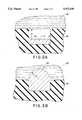
- FIGS. 2A and 2Bare cross-sectional illustrations of the electrode configurations used with the diaphragm pacer of the present invention to provide uniform current density
- FIGS. 3A-3Care top, front and side profile views of a disk used as the stimulating electrode surface of the present invention.
- FIGS. 4A and 4Bare side and profile views of the strain relief coil used for the epimysial electrode of the present invention.
- FIGS. 5A-5Care a top partial cutaway views of the disk and strain relief coil assembly of the present invention, and cross-sectional front and side views of the disk and strain relief coil assembly of the present invention;
- FIG. 6is a detailed, cross-sectional illustration of the disk and coil assembly of FIGS. 5A-5C with a lead wire assembly attached thereto;
- FIGS. 7A and 7Bare top and detailed cross-sectional views of the overall assembly enclosed in a silicon rubber housing
- FIG. 8is a perspective view illustrating the vacuum delivery device for use with a diaphragm pacer according to the present invention.
- FIGS. 9A and 9Bare partial cutaway side and end profile views of the wrench used with the vacuum delivery device of the present invention illustrated in FIG. 8.
- the stimulating surface of the electrode comprising the ventilator prosthesis of the present inventionmay be either hemispherical 52 or a flat surface 54 within a well of insulator material 56.
- the current density of the electrodes 52, 54 with respect to the surrounding tissuerepresented in the FIGURES as a saline solution 58, is critical. Uniform current density through the electrode surface prevents corrosion of the electrode and reduces damage to the tissue.
- the surface area of the electrode contacting the tissueis 10 mm 2 .
- a maximum current amplitude of 20 milliamps at a maximum frequency of 50 Hz, having a pulse width of less than 200 microsecondscan be used safely for an electrode with a surface area of 10 mm 2 .
- Each of the electrodes 52, 54 illustrated in the FIGURESare formed of stainless steel.
- the electrodescould be formed of iridium oxide to increase the safety factor for the above stimulus parameters.
- the circular stimulation surface of the hemispherical electrode 52is preferably 1.75 mm in radius wherein a 10 mm 2 surface area is provided.
- each of the electrodes 52, 54are generally encapsulated in an insulating material 56 and have a surface area carefully selected according to an intended stimulation signal. Since the surface conducts electricity between the electrode and the tissue, prevention of corrosion and reduced damage to the tissue is of utmost importance.
- the stimulating surface of the diaphragm pacer of the preferred embodimentis illustrated as being formed of a disk 60.
- the diskis generally circular having a flat top 62 and bottom 64 for the electrode with a stimulating surface in a well.
- the electrode with a hemispherical stimulating surfacehas a hemispherical protrusion on the bottom surface.
- a transverse bore 66is provided running entirely through the disk 60.
- the boreis appropriately sized to receive a strain relief coil 70 as illustrated in FIGS. 5A and 5C.
- the strain relief coil 70(FIGS. 4A, 4B) is received into the bore 66 (FIGS.
- strain relief coil 70is fixed in this position in the bore 66 by a weld of the two pieces.
- the disk 60 with the strain relief coil 70 received thereinis further provided with a coiled lead wire 80 co-axially received within the strain relief coil 70.
- the coiled lead wire 80is a multistranded stainless steel wire.
- the multistranded stainless steel wireis ideally suited for carrying current from a stimulator apparatus to the stimulating surface 64 of the disk 60.
- the coiled lead wire 80is formed into a helix having insulation removed from one end thereof (left end in FIG. 6). The helical wire 80 is passed through the strain relief coil 70 and the deinsulated wire is connected to the disk coil assembly at 82.
- the strain relief coil 70 as illustrated in the FIGUREis used to discourage severe bends at the area where the wire 80 meets the disc 60. That is, the coiled lead wire 80 is surrounded by the strain relief coil 70 as both exit from the bore 66 of the disk 60.
- a polypropylene monofilament plug 84is inserted coaxial with both the strain relief coil 70 and the coiled lead wire 80.
- the coiled lead wire 80is suitably provided with a deinsulated segment which is passed through the strain relief coil 70 and welded to the disk 60 at a weld joint 82. Once welded, the polypropylene plug 84 is inserted to prevent transfer of longitudinal stresses on the coiled lead wire to the weld joint 82.
- the last step in the fabrication of the diaphragm paceris encasement of the entire assembly illustrated in FIG. 6 in a silicone rubber form 90 having a flat bottom surface 92 and a strain relief portion 94.
- the diaphragm pacer electrode assembly 96 illustrated in FIGS. 7A and 7Bhas a stimulating surface formed of the type illustrated in FIG. 2A. That is, the stimulating surface of the device 96 is a flat surface 98 of the bottom 64 of the disk 60 (FIG. 6).
- the well walls 97are formed by the silicone covering 90 to a desired depth d illustrated in FIG. 2A. Also, as shown in FIG. 7A, the well is circular having a radius a as shown in FIG. 2A.
- the electrode assembly 96may also be formed around a suitably shaped bottom surface 64 of the disk 60 comprising a hemispherical electrode surface such as illustrated in FIG. 2B. In that case, the hemispherical surface would extend beyond the bottom 92 of the assembly 96 as illustrated by the dashed line 98' which is exaggerated for the purpose of illustration.
- FIG. 8illustrates the vacuum delivery device 100 for laparoscopic implant of the diaphragm pacer.
- the vacuum delivery device 100provides a means of placing the epimysial electrode at the optimal point on the muscle for phrenic nerve stimulation.
- the vacuum delivery device 100is designed to carry the epimysial electrode through a port and into the abdomen during a laparoscopic procedure, and hold the electrode tightly against the diaphragm muscle surface for testing phrenic nerve activation.
- the vacuum delivery deviceprovides testing at many potential implant sites because the electrode can be secured, released and resecured to many locations on the muscle surface.
- the vacuum delivery deviceholds the electrode tightly against the diaphragm muscle until it can be secured using an endoscopic stapler (not shown).
- Suctionprovides the temporary holding mechanism and the movement of the epimysial electrode is controlled by the surgeon using a specialized tool which will be described in greater detail below.
- the vacuum delivery device 100includes three (3) basic members.
- the first member 110is rectangular having continuous surfaces on three sides.
- a left side surface of the first member 110 as viewed in FIGUREis adapted to receive a first vacuum tube 102 at a first opening 112 and to fixedly receive a second vacuum tube 104 at a second opening 114.
- the first opening 112is merely an enlarged bore through the first member 110 sized slightly larger than the outer diameter of the first vacuum tube 102.
- the first member 110is provided on a bottom surface as viewed in the drawing with a first vacuum port 116.
- the vacuum port 116presents a cavity toward the surface of the diaphragm muscle.
- the diaphragmis represented in the FIGURE as a planar surface 118.
- the first vacuum port 116is connected through second port 114 to the second vacuum tube 104. Fluid suction as by the application of a suitable vacuum apparatus to the second vacuum tube 104 causes the first member 110 to adhere to the surface 118 due to the suction at the first vacuum port 116.
- a second vacuum port 126is provided on the bottom of a second member 120 as viewed in the FIGURE.
- the second vacuum port 126opens towards the surface 118 of the tissue.
- the second member 120is ported to receive the first vacuum tube 102 at an opening 122.
- Both vacuum tubes 102, 104are suitably connected to the first and second members 110, 120, by an adhesive glue, a weld, or the like.
- the vacuum delivery device 100 illustrated in FIG. 8includes a third member 130 having a bore therethrough 132 which is suitably sized to be slightly larger than the outer diameter of the first vacuum tube 102. Also, the third member 130 is provided, on the bottom as viewed in the FIGURE, with a suitable cavity 134 to receive the electrode 96 illustrated in FIGS. 7A and 7B. The electrode fits closely and is releasable from the cavity 134. The top of the third member 130 defines a hexagonal opening 136 receiving a corresponding ball head hexagonal wrench 140.
- the ball head hexagonal wrench 140includes a male hexagonal tip portion 142 defining a spherical hexagonal male member 144.
- the spherical hexagonal male member on the tip 142is provided with a bore receiving a tether 150 which is secured on one end to the third member 130 of the vacuum delivery device generally denoted as 100.
- the tether 150is a polypropylene filament.
- the major portion of the ball head hexagonal wrenchis formed from a 316 L stainless steel rigid tube 148.
- the tether 150is secured on one end to the third member 130 and is threaded through both the head 142 and the elongate portion 148 of the ball head hexagonal wrench and beyond.
- the vacuum delivery device 100defines an overall flexible housing as provided by the spaced-apart and separate first, second and third members 110, 120 and 130 respectively.
- the first through third housing membersare arranged on a first side for releasable attachment to the diaphragm pacer electrode 96.
- the first side of the composite housingfurther includes a plurality of vacuum ports 116 and 126 for communicating vacuum from the hoses 104 and 102 respectively, to the operatively associated diaphragm surface 118.
- the apparatus illustrated in FIGS. 8 and 9A-9Bprovides a surgeon with positive control over the placement of the electrode assembly 96 through the operation of the first and second vacuum tubes 102, 104 and the ball head hexagonal wrench 140.
- the apparatusis inserted into the abdominal cavity with the ball head hexagonal wrench 140 received into the hexagonal opening 136 of the third member 130.
- the vacuumis applied to the first and second vacuum tubes 102, 104, causing the first and second members 110, 120 to stick to the surface 118 of the tissue due to the suction in the first and second vacuum ports 116, 126.
- the ball head hexagonal wrench 140is withdrawn from engagement with the third member 130.
- the ball head hexagonal wrench 140remains only loosely connected to the third member 130 through the tether 150.
- the tetherbeing formed of polypropylene filament is flexible enough to permit movement of the first, second and third members 110, 120, and 130 on the surface 118 of the tissue without the influence of the rigid ball head hexagonal wrench 140.
- currentis passed through the electrode causing the diaphragm muscle to move separate and apart from the ball head hexagonal wrench 140. The quality of the selected stimulation point is thereby evaluated without the influence of the wrench 140.
- the ball head hexagonal wrench 140is reinserted into the third member 130. Insertion of the ball head hexagonal wrench is guided by the tether 150 by grasping the tether extending beyond the tube 148 (not shown) and sliding the tube over the tether toward the third member 130 and into the socket 136. This procedure is performed while maintaining the vacuum applied to the first and second vacuum tubes 102, 104.
- the suctionis removed from the vacuum tubes 102, 104 causing the first and second members 110, 120 to release their grip caused by the suction on the surface 118 of the diaphragm muscle.
- the first, second and third members 110, 120, and 130 connected directly to the ball head hexagonal wrench 140 and indirectly through the first vacuum tube 102are translatable and/or rotatable by the surgeon merely by manipulating the tube 148 of the wrench 140. This procedure is repeated until the optimal placement point is located whereupon the electrode assembly 96 is stapled to the diaphragm using an endoscopic stapler (not shown).
Landscapes
- Health & Medical Sciences (AREA)
- Physiology (AREA)
- Pulmonology (AREA)
- Engineering & Computer Science (AREA)
- Biomedical Technology (AREA)
- Nuclear Medicine, Radiotherapy & Molecular Imaging (AREA)
- Radiology & Medical Imaging (AREA)
- Life Sciences & Earth Sciences (AREA)
- Animal Behavior & Ethology (AREA)
- General Health & Medical Sciences (AREA)
- Public Health (AREA)
- Veterinary Medicine (AREA)
- Surgical Instruments (AREA)
Abstract
Description
Claims (33)
Priority Applications (3)
| Application Number | Priority Date | Filing Date | Title |
|---|---|---|---|
| US08/096,031US5472438A (en) | 1993-07-22 | 1993-07-22 | Laproscopic vacuum delivery apparatus for a diaphragm daper |
| PCT/US1994/008386WO1995003004A1 (en) | 1993-07-22 | 1994-07-22 | Ventilator prosthesis |
| AU73730/94AAU7373094A (en) | 1993-07-22 | 1994-07-22 | Ventilator prosthesis |
Applications Claiming Priority (1)
| Application Number | Priority Date | Filing Date | Title |
|---|---|---|---|
| US08/096,031US5472438A (en) | 1993-07-22 | 1993-07-22 | Laproscopic vacuum delivery apparatus for a diaphragm daper |
Publications (1)
| Publication Number | Publication Date |
|---|---|
| US5472438Atrue US5472438A (en) | 1995-12-05 |
Family
ID=22254821
Family Applications (1)
| Application Number | Title | Priority Date | Filing Date |
|---|---|---|---|
| US08/096,031Expired - LifetimeUS5472438A (en) | 1993-07-22 | 1993-07-22 | Laproscopic vacuum delivery apparatus for a diaphragm daper |
Country Status (3)
| Country | Link |
|---|---|
| US (1) | US5472438A (en) |
| AU (1) | AU7373094A (en) |
| WO (1) | WO1995003004A1 (en) |
Cited By (41)
| Publication number | Priority date | Publication date | Assignee | Title |
|---|---|---|---|---|
| US5814059A (en)* | 1997-01-08 | 1998-09-29 | Applied Medical Resources Corporation | Vein-branch accessing device |
| US5836311A (en)* | 1995-09-20 | 1998-11-17 | Medtronic, Inc. | Method and apparatus for temporarily immobilizing a local area of tissue |
| US6071295A (en)* | 1997-02-27 | 2000-06-06 | Medivas Opcab, Inc. | Device to hold an anastomotic site of coronary artery motionless and bloodless for the bypass operation |
| US6139492A (en)* | 1994-08-31 | 2000-10-31 | Heartport, Inc. | Device and method for isolating a surgical site |
| US6231585B1 (en) | 1997-11-20 | 2001-05-15 | Medivas, Llc | Device for stabilizing a treatment site and method of use |
| US6464629B1 (en) | 1998-09-15 | 2002-10-15 | Medtronic, Inc. | Method and apparatus for temporarily immobilizing a local area of tissue |
| US6494211B1 (en) | 1993-02-22 | 2002-12-17 | Hearport, Inc. | Device and methods for port-access multivessel coronary artery bypass surgery |
| US6565582B2 (en) | 1995-02-24 | 2003-05-20 | Hearport, Inc. | Devices and methods for performing a vascular anastomosis |
| US6641575B1 (en) | 1999-01-26 | 2003-11-04 | Neal M. Lonky | Surgical vacuum instrument for retracting, extracting, and manipulating tissue |
| US6656109B2 (en) | 2000-04-27 | 2003-12-02 | Medtronic, Inc. | Suction retractor for attaching to an organ within a body |
| US6663622B1 (en) | 2000-02-11 | 2003-12-16 | Iotek, Inc. | Surgical devices and methods for use in tissue ablation procedures |
| US6676597B2 (en) | 2001-01-13 | 2004-01-13 | Medtronic, Inc. | Method and device for organ positioning |
| US20050021102A1 (en)* | 2003-07-23 | 2005-01-27 | Ignagni Anthony R. | System and method for conditioning a diaphragm of a patient |
| US20050107860A1 (en)* | 2003-07-23 | 2005-05-19 | Ignagni Anthony R. | Mapping probe system for neuromuscular electrical stimulation apparatus |
| US20050203334A1 (en)* | 1999-01-26 | 2005-09-15 | Lonky Neal M. | Vacuum instrument for laparotomy procedures |
| US20060089690A1 (en)* | 2004-10-26 | 2006-04-27 | Gerber Martin T | Fixation of a medical implant to the exterior of a body organ |
| US20060190052A1 (en)* | 2005-02-18 | 2006-08-24 | Yun Anthony J | Methods and compositions for treating obesity-hypoventilation syndrome |
| US20070044669A1 (en)* | 2005-08-24 | 2007-03-01 | Geise Gregory D | Aluminum can compacting mechanism with improved actuation handle assembly |
| US7189201B2 (en) | 1995-09-20 | 2007-03-13 | Medtronic, Inc. | Method and apparatus for temporarily immobilizing a local area of tissue |
| US20070150023A1 (en)* | 2005-12-02 | 2007-06-28 | Ignagni Anthony R | Transvisceral neurostimulation mapping device and method |
| US7338434B1 (en) | 2002-08-21 | 2008-03-04 | Medtronic, Inc. | Method and system for organ positioning and stabilization |
| EP1525899A3 (en)* | 2003-10-20 | 2008-03-19 | Greatbatch-Hittman, Incorporated | Connection for a coiled lead to an electrical contact for an implantable medical device |
| US7369901B1 (en) | 2004-02-11 | 2008-05-06 | Pacesetter, Inc. | Myocardial lead and lead system |
| US7399272B2 (en) | 2004-03-24 | 2008-07-15 | Medtronic, Inc. | Methods and apparatus providing suction-assisted tissue engagement |
| US7494460B2 (en) | 2002-08-21 | 2009-02-24 | Medtronic, Inc. | Methods and apparatus providing suction-assisted tissue engagement through a minimally invasive incision |
| US20100185048A1 (en)* | 2009-01-22 | 2010-07-22 | Neal Marc Lonky | Portable regulated vacuum pump for medical procedures |
| US7794387B2 (en) | 2006-04-26 | 2010-09-14 | Medtronic, Inc. | Methods and devices for stabilizing tissue |
| US7962215B2 (en) | 2004-07-23 | 2011-06-14 | Synapse Biomedical, Inc. | Ventilatory assist system and methods to improve respiratory function |
| US8353907B2 (en) | 2007-12-21 | 2013-01-15 | Atricure, Inc. | Ablation device with internally cooled electrodes |
| US8428726B2 (en) | 2007-10-30 | 2013-04-23 | Synapse Biomedical, Inc. | Device and method of neuromodulation to effect a functionally restorative adaption of the neuromuscular system |
| US8478412B2 (en) | 2007-10-30 | 2013-07-02 | Synapse Biomedical, Inc. | Method of improving sleep disordered breathing |
| WO2014016686A3 (en)* | 2012-07-26 | 2014-04-17 | Adi Mashiach | Insert tool for selectively powering an implant unit |
| US8915894B1 (en) | 2000-01-24 | 2014-12-23 | Meditech Development Incorporated | Vacuum cup for delivery of agents during vacuum treatment |
| US8998892B2 (en) | 2007-12-21 | 2015-04-07 | Atricure, Inc. | Ablation device with cooled electrodes and methods of use |
| US9050005B2 (en) | 2005-08-25 | 2015-06-09 | Synapse Biomedical, Inc. | Method and apparatus for transgastric neurostimulation |
| US9079016B2 (en) | 2007-02-05 | 2015-07-14 | Synapse Biomedical, Inc. | Removable intramuscular electrode |
| US9186444B2 (en) | 2012-05-07 | 2015-11-17 | Meditech Development Incorporated | Portable regulated pressure devices for medical procedures |
| US9820671B2 (en) | 2007-05-17 | 2017-11-21 | Synapse Biomedical, Inc. | Devices and methods for assessing motor point electromyogram as a biomarker |
| US10052097B2 (en) | 2012-07-26 | 2018-08-21 | Nyxoah SA | Implant unit delivery tool |
| US11471683B2 (en) | 2019-01-29 | 2022-10-18 | Synapse Biomedical, Inc. | Systems and methods for treating sleep apnea using neuromodulation |
| CN115252137A (en)* | 2022-07-25 | 2022-11-01 | 江西脑虎科技有限公司 | Electrode adsorption device |
Citations (10)
| Publication number | Priority date | Publication date | Assignee | Title |
|---|---|---|---|---|
| US3640270A (en)* | 1969-08-02 | 1972-02-08 | Niess Elektromed Ingeborg | Electric contactor with venturi-suction means for organic tissue |
| US3720433A (en)* | 1970-09-29 | 1973-03-13 | Us Navy | Manipulator apparatus for gripping submerged objects |
| US3858926A (en)* | 1973-07-23 | 1975-01-07 | Ludger Ottenhues | Vacuum lifting device |
| DE2742058A1 (en)* | 1977-09-19 | 1979-03-29 | Guenter Prof Dipl Ing Dr R Rau | Fixture for data pick=up and measuring electrode - has flexible one-piece suction cup of plastics esp. for use on skin surfaces |
| DE3501339A1 (en)* | 1985-01-17 | 1986-07-17 | Robert Bosch Gmbh, 7000 Stuttgart | Suction electrode releasably fixed to a body surface by reduced pressure |
| US4899753A (en)* | 1985-10-02 | 1990-02-13 | Fukuda Denshi Co., Ltd. | Electrocardiographic electrode |
| JPH0289733A (en)* | 1988-09-28 | 1990-03-29 | Hitachi Ltd | Sheet material adsorption device |
| US4938218A (en)* | 1983-08-30 | 1990-07-03 | Nellcor Incorporated | Perinatal pulse oximetry sensor |
| US4960133A (en)* | 1988-11-21 | 1990-10-02 | Brunswick Manufacturing Co., Inc. | Esophageal electrode |
| WO1993016633A1 (en)* | 1992-02-20 | 1993-09-02 | Humanteknik Ab | A device for securing an object to a surface by vacuum |
- 1993
- 1993-07-22USUS08/096,031patent/US5472438A/ennot_activeExpired - Lifetime
- 1994
- 1994-07-22WOPCT/US1994/008386patent/WO1995003004A1/enactiveApplication Filing
- 1994-07-22AUAU73730/94Apatent/AU7373094A/ennot_activeAbandoned
Patent Citations (10)
| Publication number | Priority date | Publication date | Assignee | Title |
|---|---|---|---|---|
| US3640270A (en)* | 1969-08-02 | 1972-02-08 | Niess Elektromed Ingeborg | Electric contactor with venturi-suction means for organic tissue |
| US3720433A (en)* | 1970-09-29 | 1973-03-13 | Us Navy | Manipulator apparatus for gripping submerged objects |
| US3858926A (en)* | 1973-07-23 | 1975-01-07 | Ludger Ottenhues | Vacuum lifting device |
| DE2742058A1 (en)* | 1977-09-19 | 1979-03-29 | Guenter Prof Dipl Ing Dr R Rau | Fixture for data pick=up and measuring electrode - has flexible one-piece suction cup of plastics esp. for use on skin surfaces |
| US4938218A (en)* | 1983-08-30 | 1990-07-03 | Nellcor Incorporated | Perinatal pulse oximetry sensor |
| DE3501339A1 (en)* | 1985-01-17 | 1986-07-17 | Robert Bosch Gmbh, 7000 Stuttgart | Suction electrode releasably fixed to a body surface by reduced pressure |
| US4899753A (en)* | 1985-10-02 | 1990-02-13 | Fukuda Denshi Co., Ltd. | Electrocardiographic electrode |
| JPH0289733A (en)* | 1988-09-28 | 1990-03-29 | Hitachi Ltd | Sheet material adsorption device |
| US4960133A (en)* | 1988-11-21 | 1990-10-02 | Brunswick Manufacturing Co., Inc. | Esophageal electrode |
| WO1993016633A1 (en)* | 1992-02-20 | 1993-09-02 | Humanteknik Ab | A device for securing an object to a surface by vacuum |
Non-Patent Citations (2)
| Title |
|---|
| D. K. Peterson, T. Stellato, M. L. Nochomovitz, A. F. Dimarco, T. Abelson, and J. T. Mortimer, "Electrical Activation of Respiratory Muscles by Methods Other than Phrenic Nerve Cuff Electrodes," PACE 1989; 12:854-860. |
| D. K. Peterson, T. Stellato, M. L. Nochomovitz, A. F. Dimarco, T. Abelson, and J. T. Mortimer, Electrical Activation of Respiratory Muscles by Methods Other than Phrenic Nerve Cuff Electrodes, PACE 1989; 12:854 860.* |
Cited By (88)
| Publication number | Priority date | Publication date | Assignee | Title |
|---|---|---|---|---|
| US6494211B1 (en) | 1993-02-22 | 2002-12-17 | Hearport, Inc. | Device and methods for port-access multivessel coronary artery bypass surgery |
| US6482151B1 (en) | 1994-08-31 | 2002-11-19 | Heartport, Inc. | Method of performing a procedure on a coronary artery |
| US7025722B2 (en) | 1994-08-31 | 2006-04-11 | Heartport, Inc. | Device and method for isolating a surgical site |
| US20040254425A1 (en)* | 1994-08-31 | 2004-12-16 | Vierra Mark A. | Device and method for isolating a surgical site |
| US6821247B2 (en) | 1994-08-31 | 2004-11-23 | Heartport, Inc. | Device and method for isolating a surgical site |
| US6139492A (en)* | 1994-08-31 | 2000-10-31 | Heartport, Inc. | Device and method for isolating a surgical site |
| US6149583A (en)* | 1994-08-31 | 2000-11-21 | Heartport, Inc. | Device and method for isolating a surgical site |
| US6699257B2 (en) | 1995-02-24 | 2004-03-02 | Heartport, Inc | Devices and methods for performing a vascular anastomosis |
| US6565582B2 (en) | 1995-02-24 | 2003-05-20 | Hearport, Inc. | Devices and methods for performing a vascular anastomosis |
| US7189201B2 (en) | 1995-09-20 | 2007-03-13 | Medtronic, Inc. | Method and apparatus for temporarily immobilizing a local area of tissue |
| US6334843B1 (en) | 1995-09-20 | 2002-01-01 | Medtronic, Inc. | Method and apparatus for temporarily immobilizing a local area of tissue |
| US5836311A (en)* | 1995-09-20 | 1998-11-17 | Medtronic, Inc. | Method and apparatus for temporarily immobilizing a local area of tissue |
| US6350229B1 (en) | 1995-09-20 | 2002-02-26 | Medtronic, Inc. | Method and apparatus for temporarily immobilizing a local area of tissue |
| US6364826B1 (en) | 1995-09-20 | 2002-04-02 | Medtronic, Inc. | Method and apparatus for temporarily immobilizing a local area of tissue |
| US6371906B1 (en) | 1995-09-20 | 2002-04-16 | Medtronic, Inc. | Method and apparatus for temporarily immobilizing a local area of tissue |
| US6394948B1 (en) | 1995-09-20 | 2002-05-28 | Medtronic, Inc. | Method and apparatus for temporarily immobilizing a local area of tissue |
| US7048683B2 (en) | 1995-09-20 | 2006-05-23 | Medtronic, Inc. | Method and apparatus for temporarily immobilizing a local area of tissue |
| US6464630B1 (en) | 1995-09-20 | 2002-10-15 | Medtronic, Inc. | Method and apparatus for temporarily immobilizing a local area of tissue |
| US6755780B2 (en) | 1995-09-20 | 2004-06-29 | Medtronic, Inc. | Method and apparatus for temporarily immobilizing a local area of tissue |
| US6328688B1 (en) | 1995-09-20 | 2001-12-11 | Medtronic, Inc. | Method and apparatus for temporarily immobilizing a local area of tissue |
| US5927284A (en)* | 1995-09-20 | 1999-07-27 | Medtronic, Inc | Method and apparatus for temporarily immobilizing a local area of tissue |
| US6015378A (en)* | 1995-09-20 | 2000-01-18 | Medtronic, Inc. | Method and apparatus for temporarily immobilizing a local area tissue |
| US7445594B1 (en) | 1995-09-20 | 2008-11-04 | Medtronic, Inc. | Method and apparatus for temporarily immobilizing a local area of tissue |
| US7611455B2 (en) | 1995-09-20 | 2009-11-03 | Medtronic, Inc. | Method and apparatus for temporarily immobilizing a local area of tissue |
| US6336898B1 (en) | 1995-09-20 | 2002-01-08 | Medtronic, Inc. | Method and apparatus for temporarily immobilizing a local area of tissue |
| US5814059A (en)* | 1997-01-08 | 1998-09-29 | Applied Medical Resources Corporation | Vein-branch accessing device |
| US6071295A (en)* | 1997-02-27 | 2000-06-06 | Medivas Opcab, Inc. | Device to hold an anastomotic site of coronary artery motionless and bloodless for the bypass operation |
| US6338710B1 (en) | 1997-02-27 | 2002-01-15 | Medivas, Llc | Device for stabilizing a treatment site and method of use |
| US6231585B1 (en) | 1997-11-20 | 2001-05-15 | Medivas, Llc | Device for stabilizing a treatment site and method of use |
| US6740028B2 (en) | 1998-09-15 | 2004-05-25 | Medtronic, Inc. | Method and apparatus for temporarily immobilizing a local area of tissue |
| US7201716B2 (en) | 1998-09-15 | 2007-04-10 | Medtronic, Inc. | Method and apparatus for temporarily immobilizing a local area of tissue |
| US20070123747A1 (en)* | 1998-09-15 | 2007-05-31 | Eric Boone | Method and apparatus for temporarily immobilizing a local area of tissue |
| US6464629B1 (en) | 1998-09-15 | 2002-10-15 | Medtronic, Inc. | Method and apparatus for temporarily immobilizing a local area of tissue |
| US20050203334A1 (en)* | 1999-01-26 | 2005-09-15 | Lonky Neal M. | Vacuum instrument for laparotomy procedures |
| US8608714B2 (en) | 1999-01-26 | 2013-12-17 | Meditech Development Incorporated | Vacuum instrument for slowing or arresting the flow of blood |
| US7935094B2 (en) | 1999-01-26 | 2011-05-03 | Meditech Development Incorporated | Vacuum instrument for slowing or arresting the flow of blood |
| US20040138645A1 (en)* | 1999-01-26 | 2004-07-15 | Lonky Neal M. | Vacuum instrument for slowing or arresting the flow of blood |
| US6641575B1 (en) | 1999-01-26 | 2003-11-04 | Neal M. Lonky | Surgical vacuum instrument for retracting, extracting, and manipulating tissue |
| US8915894B1 (en) | 2000-01-24 | 2014-12-23 | Meditech Development Incorporated | Vacuum cup for delivery of agents during vacuum treatment |
| US9138216B2 (en) | 2000-01-24 | 2015-09-22 | Meditech Development Incorporated | Portable regulated vacuum pump for medical procedures |
| US6663622B1 (en) | 2000-02-11 | 2003-12-16 | Iotek, Inc. | Surgical devices and methods for use in tissue ablation procedures |
| US6656109B2 (en) | 2000-04-27 | 2003-12-02 | Medtronic, Inc. | Suction retractor for attaching to an organ within a body |
| US6676597B2 (en) | 2001-01-13 | 2004-01-13 | Medtronic, Inc. | Method and device for organ positioning |
| US7438680B2 (en) | 2001-01-13 | 2008-10-21 | Medtronic, Inc. | Method and device for organ positioning |
| US7326173B2 (en) | 2001-01-13 | 2008-02-05 | Medtronic, Inc. | Device for organ positioning |
| US7338434B1 (en) | 2002-08-21 | 2008-03-04 | Medtronic, Inc. | Method and system for organ positioning and stabilization |
| US7494460B2 (en) | 2002-08-21 | 2009-02-24 | Medtronic, Inc. | Methods and apparatus providing suction-assisted tissue engagement through a minimally invasive incision |
| US8734320B2 (en) | 2002-08-21 | 2014-05-27 | Medtronic, Inc. | Methods and apparatus providing suction-assisted tissue engagement through a minimally invasive incision |
| US8449449B2 (en) | 2002-08-21 | 2013-05-28 | Medtronic, Inc. | Methods and apparatus providing suction-assisted tissue engagement through a minimally invasive incision |
| US20050107860A1 (en)* | 2003-07-23 | 2005-05-19 | Ignagni Anthony R. | Mapping probe system for neuromuscular electrical stimulation apparatus |
| US8406885B2 (en) | 2003-07-23 | 2013-03-26 | Synapse Biomedical, Inc. | System and method for conditioning a diaphragm of a patient |
| US8706236B2 (en) | 2003-07-23 | 2014-04-22 | Synapse Biomedical, Inc. | System and method for conditioning a diaphragm of a patient |
| US20050021102A1 (en)* | 2003-07-23 | 2005-01-27 | Ignagni Anthony R. | System and method for conditioning a diaphragm of a patient |
| US7206641B2 (en) | 2003-07-23 | 2007-04-17 | University Hospitals Of Cleveland | Mapping probe system for neuromuscular electrical stimulation apparatus |
| US7840270B2 (en) | 2003-07-23 | 2010-11-23 | Synapse Biomedical, Inc. | System and method for conditioning a diaphragm of a patient |
| EP1525899A3 (en)* | 2003-10-20 | 2008-03-19 | Greatbatch-Hittman, Incorporated | Connection for a coiled lead to an electrical contact for an implantable medical device |
| US7369901B1 (en) | 2004-02-11 | 2008-05-06 | Pacesetter, Inc. | Myocardial lead and lead system |
| US7399272B2 (en) | 2004-03-24 | 2008-07-15 | Medtronic, Inc. | Methods and apparatus providing suction-assisted tissue engagement |
| US7962215B2 (en) | 2004-07-23 | 2011-06-14 | Synapse Biomedical, Inc. | Ventilatory assist system and methods to improve respiratory function |
| US7593777B2 (en)* | 2004-10-26 | 2009-09-22 | Medtronic, Inc. | Fixation of a medical implant to the exterior of a body organ |
| US20060089690A1 (en)* | 2004-10-26 | 2006-04-27 | Gerber Martin T | Fixation of a medical implant to the exterior of a body organ |
| US20060190052A1 (en)* | 2005-02-18 | 2006-08-24 | Yun Anthony J | Methods and compositions for treating obesity-hypoventilation syndrome |
| US7966072B2 (en) | 2005-02-18 | 2011-06-21 | Palo Alto Investors | Methods and compositions for treating obesity-hypoventilation syndrome |
| US20070044669A1 (en)* | 2005-08-24 | 2007-03-01 | Geise Gregory D | Aluminum can compacting mechanism with improved actuation handle assembly |
| US9050005B2 (en) | 2005-08-25 | 2015-06-09 | Synapse Biomedical, Inc. | Method and apparatus for transgastric neurostimulation |
| US20070150023A1 (en)* | 2005-12-02 | 2007-06-28 | Ignagni Anthony R | Transvisceral neurostimulation mapping device and method |
| US8676323B2 (en) | 2006-03-09 | 2014-03-18 | Synapse Biomedical, Inc. | Ventilatory assist system and methods to improve respiratory function |
| US7794387B2 (en) | 2006-04-26 | 2010-09-14 | Medtronic, Inc. | Methods and devices for stabilizing tissue |
| US8025620B2 (en) | 2006-04-26 | 2011-09-27 | Medtronic, Inc. | Methods and devices for stabilizing tissue |
| US9079016B2 (en) | 2007-02-05 | 2015-07-14 | Synapse Biomedical, Inc. | Removable intramuscular electrode |
| US9820671B2 (en) | 2007-05-17 | 2017-11-21 | Synapse Biomedical, Inc. | Devices and methods for assessing motor point electromyogram as a biomarker |
| US8478412B2 (en) | 2007-10-30 | 2013-07-02 | Synapse Biomedical, Inc. | Method of improving sleep disordered breathing |
| US9138580B2 (en) | 2007-10-30 | 2015-09-22 | Synapse Biomedical, Inc. | Device and method of neuromodulation to effect a functionally restorative adaption of the neuromuscular system |
| US8428726B2 (en) | 2007-10-30 | 2013-04-23 | Synapse Biomedical, Inc. | Device and method of neuromodulation to effect a functionally restorative adaption of the neuromuscular system |
| US8998892B2 (en) | 2007-12-21 | 2015-04-07 | Atricure, Inc. | Ablation device with cooled electrodes and methods of use |
| US8353907B2 (en) | 2007-12-21 | 2013-01-15 | Atricure, Inc. | Ablation device with internally cooled electrodes |
| US8915878B2 (en) | 2007-12-21 | 2014-12-23 | Atricure, Inc. | Ablation device with internally cooled electrodes |
| US20100185048A1 (en)* | 2009-01-22 | 2010-07-22 | Neal Marc Lonky | Portable regulated vacuum pump for medical procedures |
| US8409214B2 (en) | 2009-01-22 | 2013-04-02 | Meditech Development Incorporated | Portable regulated vacuum pump for medical procedures |
| US9186444B2 (en) | 2012-05-07 | 2015-11-17 | Meditech Development Incorporated | Portable regulated pressure devices for medical procedures |
| US9393435B2 (en) | 2012-07-26 | 2016-07-19 | Adi Mashiach | Insert tool for selectively powering an implant unit |
| WO2014016686A3 (en)* | 2012-07-26 | 2014-04-17 | Adi Mashiach | Insert tool for selectively powering an implant unit |
| US8897880B2 (en) | 2012-07-26 | 2014-11-25 | Nyxoah SA | Insert tool for selectively powering an implant unit |
| US10052097B2 (en) | 2012-07-26 | 2018-08-21 | Nyxoah SA | Implant unit delivery tool |
| US10716560B2 (en) | 2012-07-26 | 2020-07-21 | Nyxoah SA | Implant unit delivery tool |
| US11730469B2 (en) | 2012-07-26 | 2023-08-22 | Nyxoah SA | Implant unit delivery tool |
| US11471683B2 (en) | 2019-01-29 | 2022-10-18 | Synapse Biomedical, Inc. | Systems and methods for treating sleep apnea using neuromodulation |
| CN115252137A (en)* | 2022-07-25 | 2022-11-01 | 江西脑虎科技有限公司 | Electrode adsorption device |
Also Published As
| Publication number | Publication date |
|---|---|
| WO1995003004A1 (en) | 1995-02-02 |
| AU7373094A (en) | 1995-02-20 |
Similar Documents
| Publication | Publication Date | Title |
|---|---|---|
| US5472438A (en) | Laproscopic vacuum delivery apparatus for a diaphragm daper | |
| US7187981B2 (en) | Implantable electrode lead | |
| US8892217B2 (en) | Implantable medical lead with proximal retrieval wire | |
| US8538554B2 (en) | Implantable electrode, insertion tool for use therewith, and insertion method | |
| US6671544B2 (en) | Low impedance implantable extension for a neurological electrical stimulator | |
| US4744371A (en) | Multi-conductor lead assembly for temporary use | |
| US5716392A (en) | Minimally invasive medical electrical lead | |
| US7343206B2 (en) | Implantable medical lead and system, and method of use thereof | |
| US9724126B2 (en) | Introduction of medical lead into patient | |
| US4402329A (en) | Positive anchoring A-V lead | |
| CN105056397B (en) | Implantable neural electrical stimulation electrode assemblie and its application process | |
| US4044774A (en) | Percutaneously inserted spinal cord stimulation lead | |
| US8204595B2 (en) | Lead assembly for implantable microstimulator | |
| US5938596A (en) | Medical electrical lead | |
| US20160296745A1 (en) | Systems and methods for making and using improved contact arrays for electrical stimulation systems | |
| US20020103522A1 (en) | Implantable bifurcated gastrointestinal lead with active fixation | |
| US20050004639A1 (en) | Medical lead with resorbable material | |
| JP2014511232A (en) | System and method for implanting a paddle lead assembly of an electrical stimulation system | |
| US20150343198A1 (en) | Systems and methods for making and using reversible mechanical lead anchors for electrical stimulation systems | |
| US20140018885A1 (en) | Systems and methods for making and using an electrical stimulation system with a tissue-penetrating electrode | |
| AU2014290582B2 (en) | Multi-electrode lead with backing for mecho/baroreceptor stimulation | |
| EP3194015B1 (en) | Paddle leads having asymmetric electrode configurations | |
| KR20180048843A (en) | Electrotherapy system, apparatus and method | |
| US10603485B2 (en) | Features in increased surface area on neuromodulation leads | |
| US20240216675A1 (en) | Lead for the temporary stimulation of a peripheral nerve |
Legal Events
| Date | Code | Title | Description |
|---|---|---|---|
| AS | Assignment | Owner name:CASE WESTERN RESERVE UNIVERSITY Free format text:ASSIGNMENT OF ASSIGNORS INTEREST;ASSIGNORS:SCHMIT, BRIAN D.;MORTIMER, J. THOMAS;REEL/FRAME:006666/0356 Effective date:19930720 | |
| CC | Certificate of correction | ||
| REMI | Maintenance fee reminder mailed | ||
| FPAY | Fee payment | Year of fee payment:4 | |
| SULP | Surcharge for late payment | ||
| FPAY | Fee payment | Year of fee payment:8 | |
| REMI | Maintenance fee reminder mailed | ||
| FEPP | Fee payment procedure | Free format text:PAYOR NUMBER ASSIGNED (ORIGINAL EVENT CODE: ASPN); ENTITY STATUS OF PATENT OWNER: SMALL ENTITY | |
| REMI | Maintenance fee reminder mailed | ||
| FEPP | Fee payment procedure | Free format text:PETITION RELATED TO MAINTENANCE FEES FILED (ORIGINAL EVENT CODE: PMFP); ENTITY STATUS OF PATENT OWNER: SMALL ENTITY | |
| REIN | Reinstatement after maintenance fee payment confirmed | ||
| FEPP | Fee payment procedure | Free format text:PETITION RELATED TO MAINTENANCE FEES FILED (ORIGINAL EVENT CODE: PMFP); ENTITY STATUS OF PATENT OWNER: SMALL ENTITY | |
| FEPP | Fee payment procedure | Free format text:PETITION RELATED TO MAINTENANCE FEES GRANTED (ORIGINAL EVENT CODE: PMFG); ENTITY STATUS OF PATENT OWNER: SMALL ENTITY | |
| FPAY | Fee payment | Year of fee payment:12 | |
| SULP | Surcharge for late payment | ||
| FP | Lapsed due to failure to pay maintenance fee | Effective date:20071205 | |
| PTEF | Application for a patent term extension | Free format text:PRODUCT NAME: NEURX DIAPHRAGM PACING SYSTEM; REQUESTED FOR 1737 DAYS; HUMANITARIAN DEVICE EXEMPTION Filing date:20080813 Expiry date:20130722 | |
| PRDP | Patent reinstated due to the acceptance of a late maintenance fee | Effective date:20080909 | |
| STCF | Information on status: patent grant | Free format text:PATENTED CASE | |
| PTEG | Grant of a patent term extension | Free format text:PRODUCT NAME: NEURX DIAPHRAGM PACING SYSTEM; HUMANITARIAN DEVICE EXEMPTION Filing date:20080813 Expiry date:20130722 |