US5471597A - System and method for executing branch instructions wherein branch target addresses are dynamically selectable under programmer control from writable branch address tables - Google Patents
System and method for executing branch instructions wherein branch target addresses are dynamically selectable under programmer control from writable branch address tablesDownload PDFInfo
- Publication number
- US5471597A US5471597AUS08/352,299US35229994AUS5471597AUS 5471597 AUS5471597 AUS 5471597AUS 35229994 AUS35229994 AUS 35229994AUS 5471597 AUS5471597 AUS 5471597A
- Authority
- US
- United States
- Prior art keywords
- branch
- mask
- merge
- address
- instruction
- Prior art date
- Legal status (The legal status is an assumption and is not a legal conclusion. Google has not performed a legal analysis and makes no representation as to the accuracy of the status listed.)
- Expired - Lifetime
Links
Images


Classifications
- G—PHYSICS
- G06—COMPUTING OR CALCULATING; COUNTING
- G06F—ELECTRIC DIGITAL DATA PROCESSING
- G06F9/00—Arrangements for program control, e.g. control units
- G06F9/06—Arrangements for program control, e.g. control units using stored programs, i.e. using an internal store of processing equipment to receive or retain programs
- G06F9/22—Microcontrol or microprogram arrangements
- G06F9/26—Address formation of the next micro-instruction ; Microprogram storage or retrieval arrangements
- G06F9/262—Arrangements for next microinstruction selection
- G—PHYSICS
- G06—COMPUTING OR CALCULATING; COUNTING
- G06F—ELECTRIC DIGITAL DATA PROCESSING
- G06F9/00—Arrangements for program control, e.g. control units
- G06F9/06—Arrangements for program control, e.g. control units using stored programs, i.e. using an internal store of processing equipment to receive or retain programs
- G06F9/30—Arrangements for executing machine instructions, e.g. instruction decode
- G06F9/30003—Arrangements for executing specific machine instructions
- G06F9/3005—Arrangements for executing specific machine instructions to perform operations for flow control
- G06F9/30058—Conditional branch instructions
- G—PHYSICS
- G06—COMPUTING OR CALCULATING; COUNTING
- G06F—ELECTRIC DIGITAL DATA PROCESSING
- G06F9/00—Arrangements for program control, e.g. control units
- G06F9/06—Arrangements for program control, e.g. control units using stored programs, i.e. using an internal store of processing equipment to receive or retain programs
- G06F9/30—Arrangements for executing machine instructions, e.g. instruction decode
- G06F9/32—Address formation of the next instruction, e.g. by incrementing the instruction counter
- G06F9/322—Address formation of the next instruction, e.g. by incrementing the instruction counter for non-sequential address
- G06F9/323—Address formation of the next instruction, e.g. by incrementing the instruction counter for non-sequential address for indirect branch instructions
Definitions
- Microsequencer Bus Controller SystemSer. No. 08/172,657, invented by Larry L. Byers, Joseba M. De Subijana, and Wayne A. Michaelson.
- This inventionrelates generally to the processing of instructions in digital computer systems. More specifically, it relates to reduced instruction set computer (RISC) systems which use dynamic branch address tables to execute branch instructions.
- RISCreduced instruction set computer
- Control instructionsare included in the instruction set architectures of processors to provide for the proper sequencing of instructions in a program, so that the programmed task can be performed correctly and efficiently.
- One important kind of control instructionis the branch instruction.
- the branch instructionchanges the standard sequential order in which instructions in a program are executed. Branches may be conditional or unconditional. Conditional branches are taken when a specified condition has been satisfied, usually relating to the execution of the immediately preceding instruction. Unconditional branches are changes in program control that are always taken, without considering any conditions.
- a processor executes a branch instructionit typically transfers control to a branch target address referenced by the branch instruction. This branch target address is the address of an instruction to be executed rather than the next sequential instruction.
- branch target addresswas really a relative offset, either forward or backward, from the current instruction.
- the size of the branch offsetwas bound by the number of bits allocated in the branch instruction word.
- instructions known as "jumps"were used.
- a jump instructionchanged the execution sequence of a program by setting the program counter to the specified address. This alleviated the problem of limited branch target addresses. However, it was necessary for the target address to be determined at the time the program was assembled.
- Branch address tableswere devised to provide more flexibility to the assembly language programmer in determining the desired target addresses for branch instructions.
- a branch address tablecontains a set of branch target addresses. These addresses are fixed at assembly time to point to blocks of instructions known as subroutines. Program control can be changed via one of the addresses in the branch address table by selecting an entry in the table during execution of the branch instruction. In this way, the number of possible branch target addresses is expanded.
- a system using a branch address tableis described in U.S. Pat. No. 5,203,006, issued to Taniai.
- This prior art systemuses a fixed branch address table, loaded at assembly time, to reduce the number of instructions used in changing program control for a direct memory access controller.
- the limitations of this systeminclude a limited number of addresses in the table, the use of only one table, the use of direct indexing into the table, and the inflexible nature of the implementation due to the use of programmable logic arrays.
- all branch instructionsmust use the branch address table. No non-table branching was possible.
- a branch instruction that avoids these limitations yet enlarges the number of possible branch target addresses in the branch address table and provides the capability of changing the contents of the branch address table during run-timeis needed. Such an instruction would provide the maximum flexibility in selecting branch target addresses. Furthermore, a dynamic branching mechanism is needed that uses a table to change program control in only one instruction.
- a typical scheme using a "lookup" table to obtain the branch addresstakes at least four instructions after evaluation of the branch condition: a mask operation, a merge operation, a read of the table location, and a read of the entry in the table.
- a single comprehensive table branch instruction providing this functionalitywould increase processing throughput while saving space in for program storage.
- An object of this inventionis to enlarge the number of possible branch target addresses for a single branch instruction.
- Another object of this inventionis to perform a dynamic branch operation in only one instruction.
- Yet another object of this inventionis to perform branching of program control using a dynamic branch address table while minimizing the space used to store instructions for the program.
- Still another object of this inventionis to execute branch instructions in a program where the branch target address to transfer program control to may be selected from a dynamic table of branch addresses stored in random access memory (RAM) that is easily and quickly changed by the program.
- RAMrandom access memory
- Yet another object of this inventionis to execute branch instructions in a program by a processor where the branch target address to transfer program control to may be selected from one of a set of variably sized dynamic branch address tables.
- Still another object of this inventionis to execute branch instructions in a program where the branch target address to transfer program control to may be selected by a merged index, specified by the program, into a dynamic branch address table.
- a processor architecturethat implements a conditional branch instruction using a table of branch target addresses to obtain the address of where program control is to be transferred to if the branch is to be taken.
- This tablemay be updated, moved, or re-sized under program control.
- the systemdesigned to execute branch instructions fetched from a control store, comprises one or more branch address tables, each of which includes branch target addresses pointing to instructions in the control store.
- Instruction decode logicis coupled to the control store, and determines if the instruction fetched from the control store is a branch instruction. It selects one of the branch address tables to reference, and loads the specified input parameters including a base address of the selected branch address table and a mask value. It also obtains an index into the selected branch address table relative to the base address. These input parameters are used to select one of the branch target addresses previously stored in the selected branch address table.
- Local memoryis provided to dynamically read and update the branch address tables. Temporary storage is used to hold the base address, mask value, and the table index. Arithmetic, logical, and shift logic is coupled to the instruction decode logic, local memory, and parameter storage, and performs arithmetic, logical, and shift operations on the base address, mask value, and table index to produce an indicator into the selected branch address table where a selected branch target address is stored. Finally, branch control logic is coupled to the arithmetic, logical, and shift logic, and the instruction decode logic, to conditionally select the instruction addressed by either the next sequential address or the selected branch target address as the next instruction to be fetched from the control store.
- a method of transferring program control in a processor by executing a conditional branch instruction fetched from a read-only-memory control store addressed by a program counter, the processor having loaded a register with a table index during execution of the previous instructioncomprises evaluating a branch condition. A selection is made as to whether or not a branch is to be taken, depending on the branch condition evaluation. The program counter is incremented to address the next sequential instruction when the branch is not to be taken. A first register is loaded with a base address of a branch address table containing branch target addresses when the branch is to be taken. Next, a second register is loaded with a mask value. The base address is merged with the table index according to the mask value to produce an address of an entry into the branch address table. The program counter is then loaded with the branch target address from the entry, thereby effecting a change in program control.
- FIG. 1is a block diagram of the Microsequencer Bus Controller System.
- FIG. 2is a block diagram of the main components of the Microsequencer Bus Controller.
- FIG. 3is a detailed diagram illustrating the architecture of a Microsequencer Bus Controller.
- FIG. 4shows the allocation of the Local Store memory locations.
- FIG. 5shows the format of a Table Branch instruction.
- FIG. 6is a block diagram illustrating the relationships between the Local Store and internal registers in executing the Table Branch instruction.
- FIG. 7is a flow chart describing the steps performed during the execution of the Table Branch instruction.
- the Microsequencer Bus Controller Systemprovides the capability of flexible, microprocessor-based control of multiple gate arrays on a circuit card within a larger computer system. In the preferred embodiment, it is a part of a File Cache System commercially available from the assignee of the present invention. However, it may also be used in other computer systems where microprocessor control of multiple gate arrays is needed. It is a flexible solution to the problem of controlling function-specific VLSI gate arrays on one circuit card because one or more gate arrays can be changed without any other changes in the Microsequencer Bus Controller System hardware. When a gate array is changed, a corresponding change to the program the microprocessors execute may easily be made.
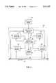
- FIG. 1is a block diagram of the Microsequencer Bus Controller System.
- the Microsequencer Bus Controller System 200contains up to eight Stations 202, 204, 206, 208, 210, 212, 214, 216 connected to a bi-directional internal communication bus called the Micro Bus 218.
- a Stationis a collection of logic implemented in a gate array on a VLSI part produced with Complementary Metal Oxide Semiconductor (CMOS) 448 technology that performs specific functions.
- CMOSComplementary Metal Oxide Semiconductor
- a Stationis coupled to the Micro Bus 218 and also may interface with another bus, I/O mechanism, or subsystem that is external to the Microsequencer Bus Controller System. That is, it may read data from or write data to other hardware components in the File Cache System.
- I/O mechanismComplementary Metal Oxide Semiconductor
- the Micro Sequencer Bus Controller (uSBC) 0 220 and uSBC 1 222are special purpose RISC microprocessors that control the operation of the Stations via the Micro Bus 218.
- the uSBCsexecute an instruction stream that is stored in the Control Store 224, a high speed static random access memory (SRAM).
- the instruction streamis written into the Control Store 224 at system initialization time.
- the instruction streamis fetched by uSBC 0 220 from the Control Store 224 over Line 226.
- the same instruction streamis fetched by uSBC 1 222 from the Control Store 224 over Line 228.
- the first microprocessor, uSBC 0 220is the master
- the second microprocessor, uSBC 1 222is the slave.
- the master and slaveexecute the same instructions at the same time but only the master microprocessor writes data on the Micro Bus 218.
- Results of operations performed by the slave microprocessor uSBC 1 222are forwarded over Line 230 to the master microprocessor uSBC 0 220, where they are compared with the results of operations performed by the master microprocessor uSBC 0 to detect any possible errors.
- the uSBCsconnect to the Micro Bus 218 over three distinct sets of lines: Address Lines 232, 234, Data Lines 236, 238, and Control Lines 240, 242.
- the Micro Bus 218is a bi-directional bus used by the uSBCs to communicate with the Stations and for data transfer between Stations. It provides access from a uSBC to hardware registers and designators resident on a Station.
- the Maintenance Clock Control (MTCC) gate array 244provides maintenance operations such as fault detection, clock distribution and control, and system reset/recovery for all components of the Microsequencer Bus Controller System 200.
- the MTCCdrives a bus enable line, which allows the uSBCs 220, 222, and the Stations to drive data on the Micro Bus 218.
- FIG. 2is a block diagram of the main components of the Microsequencer Bus Controller.
- the Instruction Decode logic 401fetches instructions from the Control Store 224 and decodes the instruction to determine which command is requested, what operands the command is to be executed with, and which one of the Stations, if any, operands are to be fetched from or the result is to be written to.
- the Arithmetic, Logical, and Shift logic 402performs the requested command by executing arithmetic, logical, or shift operations on the operands.
- the operandsare fetched from one or more Internal Registers 403 or a Local Store memory 404.
- Branch Control logic 407determines the flow of instruction control by examining signals received from Stations over the Micro Bus 218 and the results of the Arithmetic, Logical, and Shift 402 command execution.
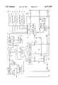
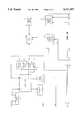
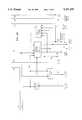
- FIG. 3,is a detailed diagram illustrating the architecture of a Microsequencer Bus Controller.
- the Control Store 224holds the instructions to be executed by the uSBC.
- the Control Store 224is accessed by the uSBC via Bi-Directional Line 226, which is controlled by Bus Control Logic 408.
- the Bus Address Register 407holds the address of the designator specified by the instruction, if any.
- the Program Counter 409is a register that holds the address of the instruction to be fetched from the Control Store 224. The instruction is retrieved from the indicated position in the Control Store 224 and stored in the Instruction Register 410 for subsequent processing. For most instructions, the Program Counter 409 is then incremented to address the next instruction in the Control Store to execute.
- MUXMultiplexor 439 controls the input to the Program Counter 409. Input is accepted from the Program Counter itself, the Instruction Register 410, and Branch Logic 440.
- the address in the Control Store where the instruction was fetched fromis saved by the Jump History logic 411 in the Local Store Write Register (LSW0) 413 (see FIG. 3B) over Line 412 and subsequently written to the Local Store 414.
- LSW0Local Store Write Register
- the Local Store 414stores data internal to the uSBC for use in executing instructions.
- the Local Store 414holds 1024 36-bit words. It is accessed by storing the address to read data from or write data to in one of four special purpose registers. These registers are the Address Read 0 415, Address Read 1 416, Address Write 0 418, and Address Write 1 420.
- Local store memory locationscan be accessed by the Arithmetic Logic Unit (ALU), MOVE, and SHIFT instructions supported by this processor more quickly than references to the uSBC's general registers. This allows the uSBC to process instructions faster than if no Local Store was available.
- the Local Store 414is implemented as a four port RAM cell.
- FIG. 4shows the allocation of the Local Store memory locations. Instructions implemented in the preferred embodiment use the Local Store 414 to hold Activity Control Block (ACB) Buffers 422, Special Purpose Variables 424, General Purpose Variables 426, and Pre-Defined Constants 428.
- the uSBC hardware logicuses the Local Store 414 to hold Branch Address Tables 430, the Call/Return Stack 432 and a Jump History Table 434.
- the Local Store address domains (from 0 to 3FF overall) of each of these data entriesare shown in hexadecimal format in FIG. 4.
- the Saved Program Counter 436is a register holding the address in the Control Store 224 where the current microcode instruction to be executed is stored. It is loaded with a value selected by MUX 437 from the current Program Counter 409, the current Saved Program Counter 436, or the output of Branch Logic 440 over Line 441.
- the Saved Program Counter 436is also stored in the Local Store 414 by Jump History logic 408.
- the Jump History Table 434holds the most recent 64 traced changes in program counter control.
- the contents of the Saved Program Counter 436are also forwarded to MUX 504 over Line 438.
- Branch Logic 440determines if the branch condition has been satisfied and if it has, then Branch Logic 440 forwards the address of the instruction to be branched to over Line 441 to MUX 439 for subsequent storage in the Program Counter 409. This causes the next instruction fetched to be the instruction stored at the branch address rather than the next sequential instruction.
- Evaluation of the branch conditionincludes reading the External Branch Condition signal 443 via External Branch Detection logic 444 if the branch instruction is an External Branch instruction. It includes accepting input from the Internal Branch Detection logic 445 if the branch instruction is an Internal Branch instruction. It also includes accepting input from the Accumulator 442 if the branch instruction is a Table Branch instruction.
- the instruction stored in the Instruction Register 410is processed by two sets of logic.
- the Command Decode Logic 446determines what kind of command is indicated by the instruction and forwards data and control information contained in the instruction to the Arithmetic Logic Unit (ALU) 448 over Line 450 and to the Station Activity Control logic 452 (shown on FIG. 3(D)) over Line 454.
- the Station Decode Logic 456determines which Station is to be referenced by the instruction, if necessary.
- the Station identification information obtained by the Station Decode Logic 456is forwarded over Line 458 to MUX 460. This Station identification information is used to select which Continue signal (1 through 8) 462 (shown on FIG. 3(D)) activation is expected as a result of the execution of the current instruction.
- the Station Decode Logic 456also forwards the Station identification information directly to the Station Activity Control logic 452 over Line 464.
- the Immediate Move Data register 466(shown on FIG. 3(A)) holds the data to be transferred to a uSBC internal register, an external register, or to the Local Store 414.
- the Immediate Move Data 466is obtained from the instruction stored in the Instruction Register 410.
- the uSBCcontains various internal registers used during processing of instructions. Operand data for an instruction is read out of the Local Store 414 and stored in general purpose Register A (REGA) 468 (see FIG. 3(B)). A mask/merge bit pattern for manipulating operand data is read out of the Local Store 414 and storm in the Mask/Merge Register (MMRG) 470.
- the Bus Receive Register (BUSR) 472(see FIG. 3(A)) is a 36-bit register that holds data, received from the Micro Bus over Line 474, resulting from an external read. It is the only uSBC register that can be written by the Micro Bus 218.
- the Accumulator (ACC) 442(see FIG. 3(C)) is a 36-bit register that holds the results of the ALU 448 after execution of an instruction. It is the only register that can output data from the uSBC to the Micro Bus 218. Therefore, every write of an external register or designator uses the ACC 442.
- the Local Store Base Register (LSBR) 476is a six bit register used for Based addressing of the Local Store 414. If Based addressing is selected, the uSBC uses the contents of LSBR 476 as the six most significant bits of the 10-bit Local Store address, and obtains the four least significant bits from the instruction. Instructions use Based addressing to access the ACB Buffers 422 within the Local Store 414.
- the Maintenance Data Out Register (MDOR) 478is used to report non-fatal errors. It is a 32-bit dynamic scan/set register connected to the Maintenance processing of the File Cache System 18 via the MTCC 244.
- the Maintenance Data In Register (MDIR) 480is a 32-bit dynamic scan/set register under the control of the Maintenance processing of the File Cache System 18 via the MTCC 244. The MDIR is used by Maintenance to send messages to the uSBC.
- the Flags Register (FLGR) 482is a hardware flags register. It contains 16 bits which are individually tested, set, and cleared. Any number of these flags can be set/cleared in one instruction. The flags are also used as branch condition indicators.
- the Source Index Register (SIXR) 484 and the Destination Index Register (DIXR) 486are 14-bit registers used for indexing external registers and as internal loop counters.
- the SIXR 484is used for indexing read requests from Local Store 414, and DIXR 486 is used for indexing write requests to Local Store 414. These registers can be automatically incremented as part of the execution of many instructions. Thus they are useful and efficient loop counters.
- the uSBCcontains two main processing groups of logic.
- the Shift/Mask/Merge unitperforms all shift operations, as well as masking and merging of operands.
- Shift logic 488selects the contents of one of the registers described above as input data via MUX 490 and MUX 491 as shown. Control of the shift, such as shift direction and length, is obtained from the Command Decode logic 446.
- the results of the Shift operationare forwarded to Mask logic 492.
- the Mask logic 492also obtains input data representing a mask bit pattern from the MMRG register 470 over Line 494. Results of the Mask logic 492 are forwarded to Merge logic 496.
- Merge logic 496also accepts input data representing an address in the Local Store 414 from REGA 468 over Line 498 or from one of the internal registers multiplexed by MUX 489. Merge logic 496 obtains a merge bit pattern from the MMRG register 470 over Line 494. The results of the Shift/Mask/Merge operation are forwarded via Line 502 and MUX 504 to the Accumulator 442.
- the ALU 448performs all arithmetic and logical operations. It processes either 32-bit or 36-bit data words, depending on the whether the uSBC is operating 32-bit or 36-bit mode.
- the ALU 448selects operand data from one of the internal registers and REGA 468 via MUX 489, or MMRG 470 over Line 494. It also obtains command information from the Command Decode Logic 446 via Line 450.
- the result of the arithmetic or logical operationis stored in the Accumulator 442 (see FIG. 3(C)) via MUX 504 and Line 508.
- the Accumulator 442selects data to store via MUX 504 from four possible sources.
- the first sourceis the Saved Program Counter 436 which forwards data over Line 438.
- the data from the Saved Program Counter 436represents the address of the instruction being executed.
- the second sourceis the output from the ALU 448 over Line 508.
- the third sourceis MUX 510 which forwards Immediate Move Data from an instruction or data from one of the internal registers over Line 512.
- the fourth sourceis the output from the Shift/Mask/Merge logic grouping over Line 502.
- the contents of the Accumulator 442may be selected by MUX 490 as an operand for the execution of a subsequent instruction via Line 514.
- the contents of the Accumulator 442are also stored in the Local Store 414 via Line 514.
- the contents of the Accumulator 442may also be written to a register on a Station connected to the Micro Bus 218.
- Bus Control Logic 516controls transfers over the bi-directional Micro Bus 218.
- the uSBCis a slave uSBC
- the contents of the Accumulator 442are forwarded over Line 230 to the master uSBC for comparison with the result stored in the master uSBC's Accumulator.
- Checker logic 518compares the two values and indicates a fatal error to the uSBC Halt logic 520 (see FIG. 3(B)) if the two values are not equal.
- the uSBC Halt logic 520stops the microprocessor. Processing is also halted if an error indication is received from one of the Stations via a Station Error 522 or Station Abort 524 signal.
- Station Error Detection logic 525receives signals from Station Error Detection logic 525 and a error indication is forwarded to uSBC Halt logic 520.
- a Lock Bus signal 324is then sent out to notify the other Stations that there is a problem.
- Multiple Continue Error Detection logic 526detects errors relating to multiple Continue signals being received by the uSBC from MUX 460 over Line 528. If such an error occurs, the uSBC Halt logic 520 stops the microprocessor. Finally, if an internal fault occurs, Internal Fault Capture logic 529 detects the error and notifies the uSBC Halt logic 520.
- Dammay be received over the Micro Bus 218 in either full-word or half-word modes.
- full-word modethe data consists of either 32 or 36 bits, depending on the mode setting of the uSBC.
- half-word modethe data consists of either 16 or 18 bits, again depending on the mode setting of the uSBC.
- the data received over the Micro Bus 218is stored in the Bus Received Register 472 after being selected by MUX 530 depending on the setting of the Half Word signal 532. If the Half Word signal is present, then the lower half of the bits in the data sent to the Bus Received Register 472 is zeroed out.
- Bus Busy Logic 536accepts as input command information from the Command Decode Logic 446 over Line 454 and Station identification information from the Station Decode Logic 456 over Line 458.
- the Bus Busy Logic 536sets the corresponding Bus Busy line to high when the uSBC is transferring data from the Accumulator 442 over the Micro Bus 218 to that particular Station.
- Station Activity Control 452implements the uSBC/Station communication protocol by setting and clearing the eight Source signals 540, the Data Destinate signal 308, four of the eight Branch On External Condition signals 320, the Latch Set signal 312, and the Latch Clear signal 316.
- Bus Wait Logic 548ensures that Station Activity Control 452 does not attempt to access the Micro Bus 218 if it is not available for data transfers.
- the Table Branch instructionis used to transfer instruction flow control in the uSBC.
- the Table Branch instructionis different from ordinary branch instructions in that it uses a dynamic input from a register as the index into a Branch Table located in the Local Store to obtain the address where control of the uSBC is to be transferred, if the branch condition is met.
- the implementation of this instructionis much more than simply setting up a hard-coded "jump" table.
- the program executing in the uSBCcan change the values in the Branch Address Table during run-time, thus the branching capability for the uSBC is flexible and not predetermined at assembly or system initialization time.
- multiple tablesare supported through the use of a based addressing scheme.
- the selection of an entry in the Branch Tableis accomplished by merging a program-specified index with the base address of the specified Branch Address Table. This approach to indexing provides the program with a fast and flexible way to access more branch addresses than by using a direct index into a hard-coded table.
- FIG. 5shows the format of the Table Branch instruction.
- the Table Branch instructionis one of the instructions in the uSBC instruction set.
- the Command (CMD) field(bits 0-2) 602, when equal to six, specifies that this is a branch instruction.
- the ST field (bits 5-6) 608controls the Call/Return Stack 432 during a branch instruction. If the ST field 608 is one and the branch condition is evaluated as true, then processing of this instruction includes popping an address off the Call/Return Stack 432. If the ST field 608 is two and the branch condition is evaluated as true, then processing of this instruction includes resetting the Call/Return Stack 432. If the ST field 608 is three, then no entry is made in the Jump History Table 434.
- the Source A field (bits 12-21) 630indicates an address in the Local Store 414 from which a Base Address (BADR) of one of the Branch Tables will be fetched and merged with the data stored in either BUSR 472 or ACC 442.
- the Merge logic 496uses the Mask/Merge control word stored at the Local Store address specified by the Mask M field (bits 22-31) 632.
- the Mask M fieldis the index into the selected Branch Table.
- the number of bits in the Mask M fieldreflects the maximum number of entries in the selected Branch Table. Since there are 10 bits allocated for this field, the maximum number of branch addresses is 2**10, or 1024 addresses.
- the maximum number of Branch Tablesis dependent only on the size of the Local Store.
- the result of mask/merge computationis the address in the Local Store 414 which contains the address in the Control Store 224 where program control is to be branched, if the branch condition is satisfied.
- FIG. 6is a block diagram illustrating the relationships between the Local Store and the internal registers used in executing the Table Branch instruction.
- the Local Store 414contains Branch Address Tables 430 which hold addresses of microcode instructions in the Control Store 224.
- the addressesare stored in the Local Store 414 starting at a Base Address (BADR) 634.
- BADRBase Address
- the contents of the memory location at BADR 634is Branch Address 0 of that Branch Address Table.
- the value BADRis initially stored at system initialization time in the Local Store 414 at a memory location 636 subsequently pointed to by the Source A field 630 of the Table Branch instruction.
- the value of the Maskwas stored at the memory location 638 pointed to by the Mask M field 632 of the Table Branch instruction.
- the Base Address and the Mask value in the Local Storemay be changed at any time by the execution of an instruction that stores new data into those entries in the Local Store.
- FIG. 7is a flow chart describing the steps performed during the execution of the Table Branch instruction. From the Start Step 640, the uSBC evaluates the branch condition 642. If the branch is not to be taken at Step 644, then the No path 646 is taken and the uSBC at Step 648 loads the Program Counter with the next sequential address in the Control Store 224.
- Step 652the uSBC performs Step 652 by loading Register A (REGA) 468 with the Base Address (BADR) of a Branch Address Table stored at the Source A 630 location 636.
- the BADRis obtained from a field in the branch instruction.
- Step 654is performed to load the Mask/Merge Register (MMRG) 470 with the Mask stored at the Mask M 632 location 638.
- a mask/merge operationis then performed at Step 656 to compute BADR and Index according to the Mask value, where Index is a table index value obtained from either the Bus Received Register (BUSR) 472 or the Accumulator (ACC) 442.
- BUSRBus Received Register
- ACCAccumulator
- Either BUSR 472 or ACC 442is loaded with the Index value at the completion of the instruction immediately preceding the Table Branch instruction.
- the branch instructionselects which register is providing the input value.
- the mask/merge operationis fully described in a related application, docket number RA-3283, entitled "System For Processing Shift, Mask, and Merge Operations In One Instruction.”
- the resulting value of the mask/merge operationis loaded into ACC 442 and indicates the address of an entry in the Branch Address Table 430 stored in Local Store 414.
- the contents of the entryis a Branch Target Address, that is, a location in the Control Store where program control should be transferred to.
- Branch Target Addressis read out of the Branch Address Table location, loaded into the ACC 442, and loaded into the Program Counter over Line 441 at Step 658. Program control is then transferred to either the Branch Target Address if the branch is to be taken or the next sequential address if the branch is not to be taken.
- the instruction addressed by the Program Counteris executed at Step 660. Table Branch instruction processing ends at Step 662.
- Branch Address Tablesmay be changed during execution time by program control because they are stored in a RAM local store.
- the tablesneed not be fixed at assembly or initialization time and remain so throughout the operational life of the system. Instead, the contents of the tables (i.e., the Branch Target Addresses) may be changed at any time.
- the programmerhas control over what address to select for branching purposes via the loading of the Base Address into the REGA 468 register.
- manipulation of the Index value in the BUSR or ACC registermay be performed to efficiently loop through a series of branches whose branch addresses are kept in the Branch Address Table. This use of based addressing greatly expands the possible choices for the branch target address.
- the base addressis masked, it allows for different Branch Address Table sizes.
- execution time of the Table Branch instruction in the preferred embodimentis less than for alternative methods of branching. For example, if a Branch Address Table contains 16 branch addresses, a four bit value could be used to adequately select a branch address. If a Table Branch Instruction is not used, to select any given branch address, the following steps must be performed. A shift and test operation would be performed for each of the four selector bits. The time to shift one bit is 100 nanoseconds (ns). The time to test a bit for a possible branch is 100 ns if the branch is taken, 200 ns if the branch is not taken. This time may be averaged as 150 ns per bit. The jump itself takes 200 ns.
- the total timewould be 1200 ns for a 16-way branch. However, with the Table Branch Instruction, this time is reduced to 350 ns. The time saved gets larger as the size of the Branch Address Table is increased. If 64 addresses were considered at a time, then a six bit value would be needed to select among the addresses. The corresponding total time would be 1700 ns. But the time used by the Table Branch Instruction remains 350 ns. Because of the expanded number of Branch Target Addresses available shown here, a branch can be taken by the processor to more possible target addresses in less time than before.
Landscapes
- Engineering & Computer Science (AREA)
- Software Systems (AREA)
- Theoretical Computer Science (AREA)
- Physics & Mathematics (AREA)
- General Engineering & Computer Science (AREA)
- General Physics & Mathematics (AREA)
- Executing Machine-Instructions (AREA)
Abstract
Description
Claims (2)
Priority Applications (1)
| Application Number | Priority Date | Filing Date | Title |
|---|---|---|---|
| US08/352,299US5471597A (en) | 1993-12-23 | 1994-12-08 | System and method for executing branch instructions wherein branch target addresses are dynamically selectable under programmer control from writable branch address tables |
Applications Claiming Priority (2)
| Application Number | Priority Date | Filing Date | Title |
|---|---|---|---|
| US17354593A | 1993-12-23 | 1993-12-23 | |
| US08/352,299US5471597A (en) | 1993-12-23 | 1994-12-08 | System and method for executing branch instructions wherein branch target addresses are dynamically selectable under programmer control from writable branch address tables |
Related Parent Applications (1)
| Application Number | Title | Priority Date | Filing Date |
|---|---|---|---|
| US17354593AContinuation | 1993-12-23 | 1993-12-23 |
Publications (1)
| Publication Number | Publication Date |
|---|---|
| US5471597Atrue US5471597A (en) | 1995-11-28 |
Family
ID=22632514
Family Applications (1)
| Application Number | Title | Priority Date | Filing Date |
|---|---|---|---|
| US08/352,299Expired - LifetimeUS5471597A (en) | 1993-12-23 | 1994-12-08 | System and method for executing branch instructions wherein branch target addresses are dynamically selectable under programmer control from writable branch address tables |
Country Status (1)
| Country | Link |
|---|---|
| US (1) | US5471597A (en) |
Cited By (19)
| Publication number | Priority date | Publication date | Assignee | Title |
|---|---|---|---|---|
| US5590351A (en)* | 1994-01-21 | 1996-12-31 | Advanced Micro Devices, Inc. | Superscalar execution unit for sequential instruction pointer updates and segment limit checks |
| US5687353A (en)* | 1995-03-03 | 1997-11-11 | Hal Computer Systems, Inc. | Merging data using a merge code from a look-up table and performing ECC generation on the merged data |
| US5740418A (en)* | 1995-05-24 | 1998-04-14 | Mitsubishi Denki Kabushiki Kaisha | Pipelined processor carrying out branch prediction by BTB |
| US5819080A (en)* | 1996-01-02 | 1998-10-06 | Advanced Micro Devices, Inc. | Microprocessor using an instruction field to specify condition flags for use with branch instructions and a computer system employing the microprocessor |
| US5822576A (en)* | 1997-03-26 | 1998-10-13 | International Business Machines Corporation | Branch history table with branch pattern field |
| US5832290A (en)* | 1994-06-13 | 1998-11-03 | Hewlett-Packard Co. | Apparatus, systems and method for improving memory bandwidth utilization in vector processing systems |
| US5956758A (en)* | 1997-10-31 | 1999-09-21 | Digital Equipment Corporation | Method for determining target address of computed jump instructions in executable programs |
| US5960212A (en)* | 1996-04-03 | 1999-09-28 | Telefonaktiebolaget Lm Ericsson (Publ) | Universal input/output controller having a unique coprocessor architecture |
| US6185674B1 (en)* | 1995-04-05 | 2001-02-06 | International Business Machines Corporation | Method and apparatus for reconstructing the address of the next instruction to be completed in a pipelined processor |
| US20030192000A1 (en)* | 2002-04-08 | 2003-10-09 | Harris Corporation | Fault-tolerant communications system and associated methods |
| US20050257033A1 (en)* | 2004-05-11 | 2005-11-17 | Stmicroelectronics, S.A. | Protection of a jump in a program |
| US20060004999A1 (en)* | 2004-06-30 | 2006-01-05 | Miyoshi Saito | Operation apparatus and operation apparatus control method |
| US20060174096A1 (en)* | 2005-02-02 | 2006-08-03 | Konigsburg Brian R | Methods and systems for storing branch information in an address table of a processor |
| US20120151153A1 (en)* | 2009-07-03 | 2012-06-14 | Axel JANTSCH | Programmable Controller |
| US8578387B1 (en)* | 2007-07-31 | 2013-11-05 | Nvidia Corporation | Dynamic load balancing of instructions for execution by heterogeneous processing engines |
| US9304775B1 (en) | 2007-11-05 | 2016-04-05 | Nvidia Corporation | Dispatching of instructions for execution by heterogeneous processing engines |
| US20160267001A1 (en)* | 2015-03-13 | 2016-09-15 | Fanuc Corporation | Monitoring device with function of extracting and displaying branch circuit in ladder program |
| US20170206087A1 (en)* | 2012-12-27 | 2017-07-20 | Intel Corporation | Collapsing of multiple nested loops, methods, and instructions |
| KR20190086020A (en)* | 2017-01-19 | 2019-07-19 | 인터내셔널 비지네스 머신즈 코포레이션 | Conditional branching to an indirectly specified position |
Citations (23)
| Publication number | Priority date | Publication date | Assignee | Title |
|---|---|---|---|---|
| US3634883A (en)* | 1969-11-12 | 1972-01-11 | Honeywell Inc | Microinstruction address modification and branch system |
| US3786434A (en)* | 1972-12-20 | 1974-01-15 | Ibm | Full capacity small size microprogrammed control unit |
| US4124893A (en)* | 1976-10-18 | 1978-11-07 | Honeywell Information Systems Inc. | Microword address branching bit arrangement |
| US4156925A (en)* | 1976-04-30 | 1979-05-29 | International Business Machines Corporation | Overlapped and interleaved control store with address modifiers |
| US4240139A (en)* | 1977-09-22 | 1980-12-16 | Tokyo Shibaura Denki Kabushiki Kaisha | Address generating system |
| US4394735A (en)* | 1979-07-25 | 1983-07-19 | A. Aoki & Associates | Data processor controlled by microprograms |
| US4635188A (en)* | 1983-07-29 | 1987-01-06 | Hewlett-Packard Company | Means for fast instruction decoding for a computer |
| US4691277A (en)* | 1984-10-24 | 1987-09-01 | International Business Machines Corp. | Small instruction cache using branch target table to effect instruction prefetch |
| US4754393A (en)* | 1984-12-21 | 1988-06-28 | Advanced Micro Devices, Inc. | Single-chip programmable controller |
| US4831573A (en)* | 1987-03-06 | 1989-05-16 | Altera Corporation | Programmable integrated circuit micro-sequencer device |
| US4864535A (en)* | 1985-12-06 | 1989-09-05 | Texas Instruments Incorporated | Entry point address circuit for microcode rom |
| US4868735A (en)* | 1984-05-08 | 1989-09-19 | Advanced Micro Devices, Inc. | Interruptible structured microprogrammed sixteen-bit address sequence controller |
| US4907192A (en)* | 1985-11-08 | 1990-03-06 | Nec Corporation | Microprogram control unit having multiway branch |
| US4984151A (en)* | 1985-03-01 | 1991-01-08 | Advanced Micro Devices, Inc. | Flexible, next-address generation microprogram sequencer |
| US5032983A (en)* | 1987-04-10 | 1991-07-16 | Tandem Computers Incorporated | Entry point mapping and skipping method and apparatus |
| US5144551A (en)* | 1989-05-19 | 1992-09-01 | Compaq Computer Corporation | Computer memory management method utilizing segmentation and protection techniques |
| US5197131A (en)* | 1988-02-10 | 1993-03-23 | Hitachi, Ltd. | Instruction buffer system for switching execution of current instruction to a branch or to a return from subroutine |
| US5197137A (en)* | 1989-07-28 | 1993-03-23 | International Business Machines Corporation | Computer architecture for the concurrent execution of sequential programs |
| US5203006A (en)* | 1988-04-22 | 1993-04-13 | Fujitsu Limited | System for selecting next instruction address between unit incremented address and address from table specified by operating condition signals |
| US5210833A (en)* | 1985-11-08 | 1993-05-11 | Nec Corporation | System for selectively masking data in a branch address register and replacing the microinstruction address register by the masked data |
| US5230068A (en)* | 1990-02-26 | 1993-07-20 | Nexgen Microsystems | Cache memory system for dynamically altering single cache memory line as either branch target entry or pre-fetch instruction queue based upon instruction sequence |
| US5235686A (en)* | 1987-02-24 | 1993-08-10 | Texas Instruments Incorporated | Computer system having mixed macrocode and microcode |
| US5297264A (en)* | 1991-04-26 | 1994-03-22 | Nec Corporation | Microprogram-controlled device comprising a control storage device with a small storage capacity |
- 1994
- 1994-12-08USUS08/352,299patent/US5471597A/ennot_activeExpired - Lifetime
Patent Citations (23)
| Publication number | Priority date | Publication date | Assignee | Title |
|---|---|---|---|---|
| US3634883A (en)* | 1969-11-12 | 1972-01-11 | Honeywell Inc | Microinstruction address modification and branch system |
| US3786434A (en)* | 1972-12-20 | 1974-01-15 | Ibm | Full capacity small size microprogrammed control unit |
| US4156925A (en)* | 1976-04-30 | 1979-05-29 | International Business Machines Corporation | Overlapped and interleaved control store with address modifiers |
| US4124893A (en)* | 1976-10-18 | 1978-11-07 | Honeywell Information Systems Inc. | Microword address branching bit arrangement |
| US4240139A (en)* | 1977-09-22 | 1980-12-16 | Tokyo Shibaura Denki Kabushiki Kaisha | Address generating system |
| US4394735A (en)* | 1979-07-25 | 1983-07-19 | A. Aoki & Associates | Data processor controlled by microprograms |
| US4635188A (en)* | 1983-07-29 | 1987-01-06 | Hewlett-Packard Company | Means for fast instruction decoding for a computer |
| US4868735A (en)* | 1984-05-08 | 1989-09-19 | Advanced Micro Devices, Inc. | Interruptible structured microprogrammed sixteen-bit address sequence controller |
| US4691277A (en)* | 1984-10-24 | 1987-09-01 | International Business Machines Corp. | Small instruction cache using branch target table to effect instruction prefetch |
| US4754393A (en)* | 1984-12-21 | 1988-06-28 | Advanced Micro Devices, Inc. | Single-chip programmable controller |
| US4984151A (en)* | 1985-03-01 | 1991-01-08 | Advanced Micro Devices, Inc. | Flexible, next-address generation microprogram sequencer |
| US5210833A (en)* | 1985-11-08 | 1993-05-11 | Nec Corporation | System for selectively masking data in a branch address register and replacing the microinstruction address register by the masked data |
| US4907192A (en)* | 1985-11-08 | 1990-03-06 | Nec Corporation | Microprogram control unit having multiway branch |
| US4864535A (en)* | 1985-12-06 | 1989-09-05 | Texas Instruments Incorporated | Entry point address circuit for microcode rom |
| US5235686A (en)* | 1987-02-24 | 1993-08-10 | Texas Instruments Incorporated | Computer system having mixed macrocode and microcode |
| US4831573A (en)* | 1987-03-06 | 1989-05-16 | Altera Corporation | Programmable integrated circuit micro-sequencer device |
| US5032983A (en)* | 1987-04-10 | 1991-07-16 | Tandem Computers Incorporated | Entry point mapping and skipping method and apparatus |
| US5197131A (en)* | 1988-02-10 | 1993-03-23 | Hitachi, Ltd. | Instruction buffer system for switching execution of current instruction to a branch or to a return from subroutine |
| US5203006A (en)* | 1988-04-22 | 1993-04-13 | Fujitsu Limited | System for selecting next instruction address between unit incremented address and address from table specified by operating condition signals |
| US5144551A (en)* | 1989-05-19 | 1992-09-01 | Compaq Computer Corporation | Computer memory management method utilizing segmentation and protection techniques |
| US5197137A (en)* | 1989-07-28 | 1993-03-23 | International Business Machines Corporation | Computer architecture for the concurrent execution of sequential programs |
| US5230068A (en)* | 1990-02-26 | 1993-07-20 | Nexgen Microsystems | Cache memory system for dynamically altering single cache memory line as either branch target entry or pre-fetch instruction queue based upon instruction sequence |
| US5297264A (en)* | 1991-04-26 | 1994-03-22 | Nec Corporation | Microprogram-controlled device comprising a control storage device with a small storage capacity |
Cited By (40)
| Publication number | Priority date | Publication date | Assignee | Title |
|---|---|---|---|---|
| US5590351A (en)* | 1994-01-21 | 1996-12-31 | Advanced Micro Devices, Inc. | Superscalar execution unit for sequential instruction pointer updates and segment limit checks |
| US5832290A (en)* | 1994-06-13 | 1998-11-03 | Hewlett-Packard Co. | Apparatus, systems and method for improving memory bandwidth utilization in vector processing systems |
| US5687353A (en)* | 1995-03-03 | 1997-11-11 | Hal Computer Systems, Inc. | Merging data using a merge code from a look-up table and performing ECC generation on the merged data |
| US6185674B1 (en)* | 1995-04-05 | 2001-02-06 | International Business Machines Corporation | Method and apparatus for reconstructing the address of the next instruction to be completed in a pipelined processor |
| US5740418A (en)* | 1995-05-24 | 1998-04-14 | Mitsubishi Denki Kabushiki Kaisha | Pipelined processor carrying out branch prediction by BTB |
| US5819080A (en)* | 1996-01-02 | 1998-10-06 | Advanced Micro Devices, Inc. | Microprocessor using an instruction field to specify condition flags for use with branch instructions and a computer system employing the microprocessor |
| US5960212A (en)* | 1996-04-03 | 1999-09-28 | Telefonaktiebolaget Lm Ericsson (Publ) | Universal input/output controller having a unique coprocessor architecture |
| US5822576A (en)* | 1997-03-26 | 1998-10-13 | International Business Machines Corporation | Branch history table with branch pattern field |
| US5956758A (en)* | 1997-10-31 | 1999-09-21 | Digital Equipment Corporation | Method for determining target address of computed jump instructions in executable programs |
| US6918068B2 (en)* | 2002-04-08 | 2005-07-12 | Harris Corporation | Fault-tolerant communications system and associated methods |
| US20030192000A1 (en)* | 2002-04-08 | 2003-10-09 | Harris Corporation | Fault-tolerant communications system and associated methods |
| US7716459B2 (en)* | 2004-05-11 | 2010-05-11 | Stmicroelectronics S.A. | Protection of a program jump from fault injection by masking a memory address with a random number |
| US20050257033A1 (en)* | 2004-05-11 | 2005-11-17 | Stmicroelectronics, S.A. | Protection of a jump in a program |
| US20060004999A1 (en)* | 2004-06-30 | 2006-01-05 | Miyoshi Saito | Operation apparatus and operation apparatus control method |
| CN100405353C (en)* | 2004-06-30 | 2008-07-23 | 富士通株式会社 | Computing device and computing device control method |
| US7725698B2 (en)* | 2004-06-30 | 2010-05-25 | Fujitsu Limited | Operation apparatus having sequencer controlling states of plurality of operation units and operation apparatus control method therefor |
| US20080276080A1 (en)* | 2005-02-02 | 2008-11-06 | International Business Machines Corporation | Methods for storing branch information in an address table of a processor |
| US7426631B2 (en)* | 2005-02-02 | 2008-09-16 | International Business Machines Corporation | Methods and systems for storing branch information in an address table of a processor |
| US7984280B2 (en) | 2005-02-02 | 2011-07-19 | International Business Machines Corporation | Storing branch information in an address table of a processor |
| US20060174096A1 (en)* | 2005-02-02 | 2006-08-03 | Konigsburg Brian R | Methods and systems for storing branch information in an address table of a processor |
| US8943301B2 (en) | 2005-02-02 | 2015-01-27 | International Business Machines Corporation | Storing branch information in an address table of a processor |
| US8578387B1 (en)* | 2007-07-31 | 2013-11-05 | Nvidia Corporation | Dynamic load balancing of instructions for execution by heterogeneous processing engines |
| US9304775B1 (en) | 2007-11-05 | 2016-04-05 | Nvidia Corporation | Dispatching of instructions for execution by heterogeneous processing engines |
| US20120151153A1 (en)* | 2009-07-03 | 2012-06-14 | Axel JANTSCH | Programmable Controller |
| US10877758B2 (en) | 2012-12-27 | 2020-12-29 | Intel Corporation | Collapsing of multiple nested loops, methods, and instructions |
| US20170206087A1 (en)* | 2012-12-27 | 2017-07-20 | Intel Corporation | Collapsing of multiple nested loops, methods, and instructions |
| US10108418B2 (en)* | 2012-12-27 | 2018-10-23 | Intel Corporation | Collapsing of multiple nested loops, methods, and instructions |
| US11640298B2 (en) | 2012-12-27 | 2023-05-02 | Intel Corporation | Collapsing of multiple nested loops, methods, and instructions |
| US11042377B2 (en) | 2012-12-27 | 2021-06-22 | Intel Corporation | Collapsing of multiple nested loops, methods, and instructions |
| US9766994B2 (en)* | 2015-03-13 | 2017-09-19 | Fanuc Corporation | Monitoring device with function of extracting and displaying branch circuit in ladder program |
| US20160267001A1 (en)* | 2015-03-13 | 2016-09-15 | Fanuc Corporation | Monitoring device with function of extracting and displaying branch circuit in ladder program |
| KR20190086020A (en)* | 2017-01-19 | 2019-07-19 | 인터내셔널 비지네스 머신즈 코포레이션 | Conditional branching to an indirectly specified position |
| US10713048B2 (en)* | 2017-01-19 | 2020-07-14 | International Business Machines Corporation | Conditional branch to an indirectly specified location |
| AU2017393885B2 (en)* | 2017-01-19 | 2020-09-17 | International Business Machines Corporation | Conditional branch to an indirectly specified location |
| TWI706325B (en)* | 2017-01-19 | 2020-10-01 | 美商萬國商業機器公司 | Computer program product, computer system and computer implemented method for conditional branch to an indirectly specified location |
| RU2723228C1 (en)* | 2017-01-19 | 2020-06-09 | Интернэшнл Бизнес Машинз Корпорейшн | Conditional transition to given indirect location |
| JP2020505674A (en)* | 2017-01-19 | 2020-02-20 | インターナショナル・ビジネス・マシーンズ・コーポレーションInternational Business Machines Corporation | Conditional branch to indirectly specified position |
| CN110192180B (en)* | 2017-01-19 | 2023-04-21 | 国际商业机器公司 | Method and computer system for processing conditional branches to indirectly specified locations |
| CN110192180A (en)* | 2017-01-19 | 2019-08-30 | 国际商业机器公司 | To the conditional branching of indirect designated position |
| JP7324142B2 (en) | 2017-01-19 | 2023-08-09 | インターナショナル・ビジネス・マシーンズ・コーポレーション | conditional branch to an indirectly specified location |
Similar Documents
| Publication | Publication Date | Title |
|---|---|---|
| US5471597A (en) | System and method for executing branch instructions wherein branch target addresses are dynamically selectable under programmer control from writable branch address tables | |
| US4074353A (en) | Trap mechanism for a data processing system | |
| EP0399762B1 (en) | Multiple instruction issue computer architecture | |
| EP0068163B1 (en) | Instruction address stack in the data memory of an instruction-pipelined processor | |
| US5487159A (en) | System for processing shift, mask, and merge operations in one instruction | |
| EP0399760B1 (en) | Paired instruction processor branch recovery mechanism | |
| US4679140A (en) | Data processor with control of the significant bit lengths of general purpose registers | |
| EP0405489A2 (en) | Resource conflict detection method and apparatus included in a pipelined processing unit | |
| US5890222A (en) | Method and system for addressing registers in a data processing unit in an indirect addressing mode | |
| EP0644482B1 (en) | Dispatch of instructions to multiple execution units | |
| US3983541A (en) | Polymorphic programmable units employing plural levels of phased sub-instruction sets | |
| EP0399757A2 (en) | Paired instruction processor precise exception handling mechanism | |
| KR900003591B1 (en) | Data processing device | |
| US4255785A (en) | Microprocessor having instruction fetch and execution overlap | |
| US5493669A (en) | Data processor for simultaneously searching two fields of the rename buffer having first and second most recently allogated bits | |
| WO1991003784A1 (en) | Improved cpu pipeline having register file bypass on update/access address compare | |
| US4491908A (en) | Microprogrammed control of extended integer and commercial instruction processor instructions through use of a data type field in a central processor unit | |
| NZ201809A (en) | Microprocessor | |
| US6145075A (en) | Apparatus and method for executing a single-cycle exchange instruction to exchange contents of two locations in a register file | |
| US5560025A (en) | Entry allocation apparatus and method of same | |
| US5034879A (en) | Programmable data path width in a programmable unit having plural levels of subinstruction sets | |
| EP1059579A2 (en) | Information processor and method for switching register files | |
| US5539888A (en) | System and method for processing external conditional branch instructions | |
| US5495598A (en) | Stuck fault detection for branch instruction condition signals | |
| US5537627A (en) | Microprogrammable processor capable of accessing unused portions of control store as fast data memory |
Legal Events
| Date | Code | Title | Description |
|---|---|---|---|
| STCF | Information on status: patent grant | Free format text:PATENTED CASE | |
| FPAY | Fee payment | Year of fee payment:4 | |
| FPAY | Fee payment | Year of fee payment:8 | |
| FPAY | Fee payment | Year of fee payment:12 | |
| AS | Assignment | Owner name:UNISYS CORPORATION, PENNSYLVANIA Free format text:RELEASE BY SECURED PARTY;ASSIGNOR:CITIBANK, N.A.;REEL/FRAME:023312/0044 Effective date:20090601 Owner name:UNISYS HOLDING CORPORATION, DELAWARE Free format text:RELEASE BY SECURED PARTY;ASSIGNOR:CITIBANK, N.A.;REEL/FRAME:023312/0044 Effective date:20090601 Owner name:UNISYS CORPORATION,PENNSYLVANIA Free format text:RELEASE BY SECURED PARTY;ASSIGNOR:CITIBANK, N.A.;REEL/FRAME:023312/0044 Effective date:20090601 Owner name:UNISYS HOLDING CORPORATION,DELAWARE Free format text:RELEASE BY SECURED PARTY;ASSIGNOR:CITIBANK, N.A.;REEL/FRAME:023312/0044 Effective date:20090601 | |
| AS | Assignment | Owner name:UNISYS CORPORATION, PENNSYLVANIA Free format text:RELEASE BY SECURED PARTY;ASSIGNOR:CITIBANK, N.A.;REEL/FRAME:023263/0631 Effective date:20090601 Owner name:UNISYS HOLDING CORPORATION, DELAWARE Free format text:RELEASE BY SECURED PARTY;ASSIGNOR:CITIBANK, N.A.;REEL/FRAME:023263/0631 Effective date:20090601 Owner name:UNISYS CORPORATION,PENNSYLVANIA Free format text:RELEASE BY SECURED PARTY;ASSIGNOR:CITIBANK, N.A.;REEL/FRAME:023263/0631 Effective date:20090601 Owner name:UNISYS HOLDING CORPORATION,DELAWARE Free format text:RELEASE BY SECURED PARTY;ASSIGNOR:CITIBANK, N.A.;REEL/FRAME:023263/0631 Effective date:20090601 | |
| AS | Assignment | Owner name:DEUTSCHE BANK TRUST COMPANY AMERICAS, AS COLLATERA Free format text:PATENT SECURITY AGREEMENT (PRIORITY LIEN);ASSIGNOR:UNISYS CORPORATION;REEL/FRAME:023355/0001 Effective date:20090731 | |
| AS | Assignment | Owner name:DEUTSCHE BANK TRUST COMPANY AMERICAS, AS COLLATERA Free format text:PATENT SECURITY AGREEMENT (JUNIOR LIEN);ASSIGNOR:UNISYS CORPORATION;REEL/FRAME:023364/0098 Effective date:20090731 | |
| AS | Assignment | Owner name:GENERAL ELECTRIC CAPITAL CORPORATION, AS AGENT, IL Free format text:SECURITY AGREEMENT;ASSIGNOR:UNISYS CORPORATION;REEL/FRAME:026509/0001 Effective date:20110623 | |
| AS | Assignment | Owner name:UNISYS CORPORATION, PENNSYLVANIA Free format text:RELEASE BY SECURED PARTY;ASSIGNOR:DEUTSCHE BANK TRUST COMPANY;REEL/FRAME:030004/0619 Effective date:20121127 | |
| AS | Assignment | Owner name:UNISYS CORPORATION, PENNSYLVANIA Free format text:RELEASE BY SECURED PARTY;ASSIGNOR:DEUTSCHE BANK TRUST COMPANY AMERICAS, AS COLLATERAL TRUSTEE;REEL/FRAME:030082/0545 Effective date:20121127 | |
| AS | Assignment | Owner name:UNISYS CORPORATION, PENNSYLVANIA Free format text:RELEASE BY SECURED PARTY;ASSIGNOR:WELLS FARGO BANK, NATIONAL ASSOCIATION (SUCCESSOR TO GENERAL ELECTRIC CAPITAL CORPORATION);REEL/FRAME:044416/0358 Effective date:20171005 |