US5471372A - Lighting system for commercial refrigerator doors - Google Patents
Lighting system for commercial refrigerator doorsDownload PDFInfo
- Publication number
- US5471372A US5471372AUS08/163,741US16374193AUS5471372AUS 5471372 AUS5471372 AUS 5471372AUS 16374193 AUS16374193 AUS 16374193AUS 5471372 AUS5471372 AUS 5471372A
- Authority
- US
- United States
- Prior art keywords
- bulb
- base
- lens
- facets
- plane
- Prior art date
- Legal status (The legal status is an assumption and is not a legal conclusion. Google has not performed a legal analysis and makes no representation as to the accuracy of the status listed.)
- Expired - Lifetime
Links
Images


Classifications
- A—HUMAN NECESSITIES
- A47—FURNITURE; DOMESTIC ARTICLES OR APPLIANCES; COFFEE MILLS; SPICE MILLS; SUCTION CLEANERS IN GENERAL
- A47F—SPECIAL FURNITURE, FITTINGS, OR ACCESSORIES FOR SHOPS, STOREHOUSES, BARS, RESTAURANTS OR THE LIKE; PAYING COUNTERS
- A47F11/00—Arrangements in shop windows, shop floors or show cases
- A47F11/06—Means for bringing about special optical effects
- A47F11/10—Arrangements of light sources
- F—MECHANICAL ENGINEERING; LIGHTING; HEATING; WEAPONS; BLASTING
- F21—LIGHTING
- F21V—FUNCTIONAL FEATURES OR DETAILS OF LIGHTING DEVICES OR SYSTEMS THEREOF; STRUCTURAL COMBINATIONS OF LIGHTING DEVICES WITH OTHER ARTICLES, NOT OTHERWISE PROVIDED FOR
- F21V13/00—Producing particular characteristics or distribution of the light emitted by means of a combination of elements specified in two or more of main groups F21V1/00 - F21V11/00
- F21V13/02—Combinations of only two kinds of elements
- F21V13/04—Combinations of only two kinds of elements the elements being reflectors and refractors
- F—MECHANICAL ENGINEERING; LIGHTING; HEATING; WEAPONS; BLASTING
- F21—LIGHTING
- F21V—FUNCTIONAL FEATURES OR DETAILS OF LIGHTING DEVICES OR SYSTEMS THEREOF; STRUCTURAL COMBINATIONS OF LIGHTING DEVICES WITH OTHER ARTICLES, NOT OTHERWISE PROVIDED FOR
- F21V5/00—Refractors for light sources
- F21V5/02—Refractors for light sources of prismatic shape
- F—MECHANICAL ENGINEERING; LIGHTING; HEATING; WEAPONS; BLASTING
- F25—REFRIGERATION OR COOLING; COMBINED HEATING AND REFRIGERATION SYSTEMS; HEAT PUMP SYSTEMS; MANUFACTURE OR STORAGE OF ICE; LIQUEFACTION SOLIDIFICATION OF GASES
- F25D—REFRIGERATORS; COLD ROOMS; ICE-BOXES; COOLING OR FREEZING APPARATUS NOT OTHERWISE PROVIDED FOR
- F25D27/00—Lighting arrangements
- F—MECHANICAL ENGINEERING; LIGHTING; HEATING; WEAPONS; BLASTING
- F21—LIGHTING
- F21W—INDEXING SCHEME ASSOCIATED WITH SUBCLASSES F21K, F21L, F21S and F21V, RELATING TO USES OR APPLICATIONS OF LIGHTING DEVICES OR SYSTEMS
- F21W2131/00—Use or application of lighting devices or systems not provided for in codes F21W2102/00-F21W2121/00
- F21W2131/30—Lighting for domestic or personal use
- F21W2131/305—Lighting for domestic or personal use for refrigerators
Definitions
- the present inventionrelates generally to commercial refrigerator units of the type which have glass doors for viewing merchandise from the front side thereof, and more particularly, to lighting systems for illuminating products contained within the refrigerator.
- the general aim of the present inventionis to provide a commercial refrigerator lighting system which enables more aesthetically pleasing display of merchandise within the refrigerator cabinet.
- Another object of the inventionis to provide a lighting system as characterized above which effects substantially uniform illumination of the displayed merchandise.
- a further objectis to provide a lighting system of the above kind which neither creates a glare to the passing customer nor which creates a zebra effect in a long display cabinet in which a plurality of vertically disposed fluorescent lamps are located along the length thereof.
- Another objectis to provide a lighting system of the foregoing type in which the light output of fluorescent bulbs used in the system is substantially unaffected by the cold temperature within the refrigerator case.
- a further objectis to provide a lighting system of such type which is relative compact in construction and which lends itself to economical installation.
- the inventionresides in the provision of a lighting system in which properties of both reflection and refraction are utilized to produce an improved illumination gradient across a target plane located in close proximity to the bulb, this being achieved through the use of a non-imaging lens/reflector unit for redirecting light traveling in one direction and for causing such light to combine with light emanating from another part of the bulb.
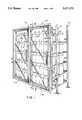
- FIG. 1is a front perspective view of a typical commercial refrigerator unit equipped with a new and improved lighting system incorporating the unique features of the present invention.
- FIGS. 2 and 3are enlarged fragmentary cross-sections taken substantially along the lines 2--2 and 3--3, respectively, of FIG. 1.
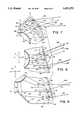
- FIG. 4is an enlarged view of one type of light fixture shown in FIG. 3.
- FIG. 5is an enlarged view of another type of light fixture shown in FIG. 3.
- FIG. 6is an exploded perspective view of certain components of the light fixture shown in FIG. 5.
- FIGS. 7, 8 and 9are diagrammatic views showing the propagation of light rays from different sections of the light fixture of FIG. 4.
- FIG. 10is a graph illustrating the improvement in light distribution of the lighting system of the present invention when compared with a system having a bare fluorescent bulb.
- an illustrative refrigerator door assembly 10comprising a pair of insulated glass doors 11A and 11b each mounted for swinging movement in a door mounting cabinet frame 12 which in turn is mounted within an opening in a front wall 13 (FIG. 3) of a refrigerator cabinet or the like. It will be understood that the door assembly 10 is particularly adapted for use in free standing refrigerator or freezer cases or built-in coolers or cabinets of the type used in supermarkets and other retail stores to display refrigerated or frozen merchandise.
- the door mounting frame 12which may be of a conventional construction, extends about the periphery of the opening in the wall 13 and includes a center frame member or mullion 14 extending vertically between the top and bottom perimeters of the frame to provide rigidity for the frame 12 and defining a sealing surface against which sides of the doors 11A and 11B engage when in a closed condition.
- the cabinet frame 12includes a plurality of frame members 15 (FIGS. 3 and 4), preferably in the form of extrusions made of aluminum or other suitable metal material, arranged in a rectangular configuration about the periphery of the cabinet opening.
- the illustrated frame members 15have a generally Z-shaped configuration comprising a front flange 16 (FIG. 4), a rear flange 18, and a web 19 extending therebetween.
- the front and rear flanges 16, 18project in opposite directions, generally at right angles to the web 19.
- a plate 20 located forwardly of the flange 18provides a sealing surface against which the doors 11A and 11B close.
- An insulating strip 21, preferably made of plastic,is interposed between the frame member web 19 and the cabinet wall 13 and, in this case, extends rearwardly into the cabinet.
- the center mullion 14is generally similar to the frame members 15 and includes a vertically extending plate 22 (FIG. 5) defining a sealing face for the doors 11A and 11B.
- the door 11Bis hinged at 23 adjacent the mullion while the door 11A is hinged at 24 (FIG. 4) near one of the vertically extending portions of the frame members 15.
- the free edge of the door 11Bseals against the plate 20 of the opposite vertically extending frame member portion while the free edge of the door 11A seals against the plate 22 of the mullion 14.
- the insulated glass doors 11A and 11Bmay be of a conventional type, which include an insulated glass unit comprising a plurality of glass panes 26 (FIG. 5) disposed in parallel side-by-side relation and separated by spacers 27.
- each doorhas an outer frame assembly, the rear side of which carries a gasket 28 for sealing engagement with the plates 20 and 22.
- a plurality of vertically spaced shelves 30, such as wire rod type,are provided.
- the shelves 30typically are supported on front and rear support posts 31, the front posts being secured to the door frame 12 by brackets 32 or other suitable means.
- brackets 32or other suitable means.
- vertical light fixtures 35 and 36are supported rearwardly of the door frame 12 immediately in front of the shelves 30.
- an end light fixture 35is located adjacent each vertically extending portion of the frame member 15 while a center light fixture 36 is located directly behind the center mullion 14 (see FIG. 3).
- Each light fixture 35, 36in this instance comprises an elongated channel-shaped base 37 extending vertically of the doors 11A and 11B.
- the bases for the two end fixtures 35are attached to the flanges 18 of the frame members 15 (see FIG. 4) while the base for the center fixture 36 is attached to the mullion 14 as shown in FIG. 5.
- Electrical sockets 38(FIG. 6) are attached by screws 39 to the upper and lower end portions of each base and may be connected to an electrical outlet on the frame 12, as is known in the art.
- a replaceable light bulb 40which preferably is of the fluorescent type, includes terminals 41 which are adapted to be plugged into the sockets. Each bulb extends vertically and is spaced just a short distance in front of the shelves 30.
- a transparent plastic, elongated tube 42(FIG. 6) is concentrically mounted about the bulb to define an air insulating space 43 between the bulb and the tube.
- plastic end caps 44are provided at opposite ends of the tube.
- Each end caphas a first tubular portion 45 over which an end of the tube is snugly telescoped and a radial locating flange 46 against which the end of the tube abuts.
- the end caphas a second tubular portion 47 for receiving the end portion of the bulb and formed with an end wall through which the terminals 41 project.
- a sleeve 48Integral with the second tubular portion of the end cap is a sleeve 48 adapted to telescope releasably over the socket 38 to enable the terminals 41 to plug into the female contacts of the socket.
- each light fixture 35is located just in front of the outboard ends of the shelves 30 while the light fixture 36 is located just in front of the center of the two tiers of shelves.
- each light fixtureis constructed so as to effect a substantially uniform distribution of light energy horizontally across a target plane TP which herein is a forwardly facing vertical plane containing the front edges of the shelves.
- each of the fixtures 35, 36 hereincomprises a vertically extending reflector 50 supported on the base 37 and located between the base and the front of the bulb 40.
- Each reflectoris a substantially V-shaped member having two wings 51 disposed at right angles to each other and joining one another at an apex 52 (FIG. 9) which points toward the bulb and which is centered laterally with respect to the axis A of the bulb.
- the reflectoris made of sheet metal and the rearwardly facing surfaces of the wings have a shiny, mirror-like finish.
- Lips 53 (FIG. 9) projecting from the base 37receive the free edge portions of the wings and serve to hold the reflector in assembled relation with the base.
- a uniquely constructed lensboth reflects and refracts light from the bulb 40 of each fixture 35, 36 and coacts with the reflector 50 of the fixture to distribute the light energy substantially uniformly across the target plane TP.
- the lens for the left end fixture 35is shown in FIG. 4, has been indicated generally by the reference numeral 55 and will be described in detail.
- the lens 55' (FIG. 3) for the right end fixture 35is a mirror image of the lens 55 and thus need not be specifically described.
- the center fixture 36includes a lens 56 which will be described subsequently.
- the lens 55is extruded from a single piece of clear acrylic and has a nominal wall thickness of about 0.010".
- the lensmay best be described as being partly transparent in that an object within the lens can be seen and distinguished but not with the clarity that would prevail with a truly transparent lens.
- the forward end of the lens 55includes a laterally extending flange 57 (FIG. 4) which seats against the rear face of the base 32.
- the flange 57is located forwardly and to the right of the bulb 40 of the left-hand light fixture 35.
- the lens 55includes a first portion 58 joined to the flange 57 and inclined at an acute included angle relative to the base 37 such that the first portion 58 converges toward the bulb 40 as it progresses rearwardly.
- the first portion 58 of the lensextends rearwardly from the flange to a location approximately even with the rear side of the bulb.
- the lens 55includes a second portion 59 (FIG. 4) which is inclined at an obtuse included angle relative to the first portion 58 and which extends rearwardly from the rear end of the first portion and toward a vertical plane X containing the axis A of the bulb 40 and disposed perpendicular to the target plane TP at the front of the shelves 30.
- the second lens portion 59extends rearwardly to a location beyond the rear side of the bulb and terminates prior to reaching the plane X.
- a third lens portion 60is joined to the rear end of the second lens portion 59, is inclined at an acute included angle relative thereto and extends forwardly therefrom to a position spaced just forwardly of the rear side of the bulb 40 and located in the plane X.
- the inner sides of the first, second and third portions 58, 59 and 60are formed with multiple facets 61 which will be described subsequently.
- the lensalso includes a non-faceted portion 62 which engages the side of the insulating strip 21, the rear end of the strip being formed with a flange 63 which hooks around part of the non-faceted portion.
- the inner sides of the portions 58, 59 and 60 of the lens 55includes multiple facets 61 which herein are in the form of vertically extending and generally V-shaped ribs.
- the inner side of the first lens portion 58includes a first group of generally V-shaped facets 65 (FIGS. 8 and 9) each having long and short legs 66 and 67 which join one another at acute included angles.
- the long legs 66 of the facets 65are generally parallel to one another and face generally forwardly toward the reflector 50.
- the short legs 67 of the facets 65also are generally parallel to one another and face generally rearwardly away from the reflector.
- the lensincludes five facets 65. Those facets are located between the base 37 and a vertical plane Z extending perpendicular to the plane X and containing the axis A of the bulb. The plane Z, of course, extends parallel to the target plane TP.
- the inner side of the first portion 58 of the lens 55also includes a single generally V-shaped facet 68 (FIG. 8) whose legs 69 join one another at an obtuse included angle having an apex located closely adjacent the plane Z.
- the facet 68is located next to the rearmost facet 65 and forms a transition between those facets and another group of facets 70 (FIGS. 7 and 8) formed on the inner side of the first lens portion 58.
- the long legs 71 of the facets 70extend generally parallel to and face the plane X while the short legs 72 thereof face generally forwardly.
- each facet 73includes long and short legs 74 and 75 joining one another at an acute included angle, with the long legs 74 extending generally parallel to and facing the plane X and with the short legs 75 facing generally forwardly.
- the third lens portion 59includes a plurality (herein, two) of generally V-shaped facets 76 each having long and short legs 77 and 78 which join one another at an acute included angle.
- the long legs 77 of the facets 76are generally parallel to one another and face generally away from the plane X and the reflector 50.
- the short legs 78 of the facets 76also are generally parallel to one another and face generally toward the reflector.
- the rear end of the short leg 78 of the forwardmost facet 76is located in the plane X.
- the lens 55is considered to comprise three sections A, B and C (FIG. 4 and FIGS. 7-9) designed to send as much light as possible horizontally to the right within the target plane TP.
- Section A of the lensincludes part of the first lens portion 58 and extends rearwardly from the flange 57 to a location somewhat rearwardly of the reflector 50 and approximately to the short leg 67 of the third facet 65 from the front.
- the main function of section A of the lensis to refract light that is reflected off of the reflector 50 and to redirect it toward the target plane TP. Rays 80 and 81 shown in FIG. 9 are illustrative of this phenomenon.
- Each facet 65 of section Aalso plays other important roles to enhance the performance of the fixture 35.
- Optical section B of the lens 55extends generally from section A to the rear end of the long leg 74 of the forwardmost facet 73.
- Section Bis somewhat functionally similar to a large facet Fresnel lens but has been optimized to control rays from different portions of the bulb 40.
- the angles of the long legs 66 of the facets 65are comparatively large relative to vertical and thus provide more bending of the rays. This is beneficial because rays such as the rays 85 and 86 (FIG. 8) generally originate from points located forwardly of the long legs 66 of the facets 65, thus requiring that the rays be bent through large angles in order to redirect the light toward the target plane TP.
- the facets 70 of section Bare oriented in the opposite direction from the facets 65 and, in this part of the lens 55, the rays are bent away from the end portion of the target plane TP and are redirected toward the right thereof as indicated by the rays 87 and 88 (FIG. 8).
- the facet 70promotes light redistribution as displayed by the ray 89 in FIG. 8. That ray enters the facet 70 through its long leg 71, is reflected off of the short leg 72 because of total internal reflection and continues on to illuminate the target plane TP.
- Optical section C of the lens 55comprises the second and third lens geometric portions 59 and 60.
- the main function of the portion 60 of section Cis to cause the light to reflect internally at the outer surface of the lens.
- the facets 73 and 76 of section Care oriented such that refraction at the inner side of the lens is minimized.
- light from the rearward area of the bulb 40 as exemplified by the ray 90travels in a relatively undeviated path as it passes through the inner side of the lens.
- its angleis such that total internal reflection results, causing the light to be directed away from the end of the target plane TP and toward the right thereof.
- Rays such as the ray 91are refracted away from the vicinity of the bulb 40 in order to illuminate the center of the target plane. Rays 92 and 93 do not directly strike the target plane but, as a result of reflection and/or refraction, are deviated away from the vicinity of the bulb 40 so as to reduce the light intensity in that vicinity and impart uniformity to the illumination gradient.
- the non-faceted section 62 of the lens 35coacts with the insulating strip 21 to define baffling at the left side of the fixture 35 to direct light toward the right thereof.
- FIG. 5shows the lens 56 for the center light fixture 36.
- the right side of such lensis identical to the right side of the lens 55 in that the right side of the lens 56 includes first, second and third geometric portions 58, 59 and 60 identical to the first, second and third portions 58, 59 and 60, respectively, of the lens 55.
- the left side of the center lens 56includes fourth, fifth and sixth portions 58', 59', and 60' which are mirror images of the first, second and third portions 58, 59 and 60, respectively, of the lens 56.
- the fourth portion 58' of the lens 56includes a flange 57' which seats against the base 37 on the side of the reflector 50 opposite the flange 57 while the sixth portion 60' of the lens 56 is joined to the third portion 60 thereof in the plane X.
- each tier of shelves 30are illuminated with light which has generally the same intensity as the light at the ends of the shelves.
- FIG. 10is a graph showing the change in light level as a function of horizontal distance along the target plane TP from the light source and demonstrates the improvement obtained by the present lens/reflector system, where light level is indicated by a dashed line 95, as compared to a bare bulb of the same wattage and of the same physical size and shape, the light level of the bare bulb being indicated by the solid line 96. From FIG. 10, it is apparent that the light level of the present system is less adjacent the bulb but is greater remote from the bulb so as to provide a more uniform gradient.
- the more uniform gradientnot only casts more light on products remote from the source (i.e., at the center of each tier of shelves 30) but also reduces glare at the ends of the shelves. This, together with the retention of light within the fixtures 35 and 36, reduces the zebra effect and enhances the visibility of the colors and the graphics of the products.
- each lens 55, 56is clamped to the base 37 in a manner permitting quick and easy removal of the lens for purposes of changing the bulb 40.
- the insulating strip 21includes a wing 100 (FIG. 4) which engages the flange 57 along the length thereof.
- Clamps 101are spaced along the base and each includes a tongue 102 adapted to engage the side of the lens adjacent the wing.
- a screw 103When a screw 103 is tightened, the tongue 102 pushes the lens to the left and presses the non-faceted portion 62 thereof against the strip 21, the flange 63 captivating the lens against rearward movement.
- the tongues 102may be released from engagement with the lens and the latter may be pulled forwardly from the resilient flange 63 and wing 100.
- a similar arrangementis used to hold the center lens 56.
- wings 100 and 100'made of resiliently yieldable plastic are fixed relative to the base 37 and engage the sides of the lens adjacent the flanges 57 and 57' thereof.
- Clamps 101 and 101'are spaced along opposite sides of the lens 56 and include tongues 102 and 102'.
- screws 103 and 103'are tightened, the lens is clamped between the tongues.
- the screwsare loosened to release the tongues, the lens may be snapped forwardly past the wings.
- the lens 55 and 56coact with the tubes 42 to provide a double insulating jacket around each bulb. As a result, the bulbs are better protected from the cold temperatures in the refrigerator cabinet and are capable of producing greater light output.
Landscapes
- Engineering & Computer Science (AREA)
- General Engineering & Computer Science (AREA)
- Chemical & Material Sciences (AREA)
- Combustion & Propulsion (AREA)
- Physics & Mathematics (AREA)
- Mechanical Engineering (AREA)
- Thermal Sciences (AREA)
- Devices That Are Associated With Refrigeration Equipment (AREA)
- Non-Portable Lighting Devices Or Systems Thereof (AREA)
Abstract
Description
Claims (29)
Priority Applications (5)
| Application Number | Priority Date | Filing Date | Title |
|---|---|---|---|
| US08/163,741US5471372A (en) | 1993-12-06 | 1993-12-06 | Lighting system for commercial refrigerator doors |
| CA002136695ACA2136695A1 (en) | 1993-12-06 | 1994-11-25 | Lighting system for commercial refrigerator doors |
| AU79097/94AAU7909794A (en) | 1993-12-06 | 1994-11-29 | Lighting system for commercial refrigeration doors |
| NO944684ANO944684L (en) | 1993-12-06 | 1994-12-05 | Lighting system for cooling units |
| EP94309040AEP0657708A1 (en) | 1993-12-06 | 1994-12-05 | Lighting system for commercial refrigerator doors |
Applications Claiming Priority (1)
| Application Number | Priority Date | Filing Date | Title |
|---|---|---|---|
| US08/163,741US5471372A (en) | 1993-12-06 | 1993-12-06 | Lighting system for commercial refrigerator doors |
Publications (1)
| Publication Number | Publication Date |
|---|---|
| US5471372Atrue US5471372A (en) | 1995-11-28 |
Family
ID=22591372
Family Applications (1)
| Application Number | Title | Priority Date | Filing Date |
|---|---|---|---|
| US08/163,741Expired - LifetimeUS5471372A (en) | 1993-12-06 | 1993-12-06 | Lighting system for commercial refrigerator doors |
Country Status (5)
| Country | Link |
|---|---|
| US (1) | US5471372A (en) |
| EP (1) | EP0657708A1 (en) |
| AU (1) | AU7909794A (en) |
| CA (1) | CA2136695A1 (en) |
| NO (1) | NO944684L (en) |
Cited By (52)
| Publication number | Priority date | Publication date | Assignee | Title |
|---|---|---|---|---|
| US5645330A (en)* | 1996-09-19 | 1997-07-08 | Ardco Incorporated | Refrigerated display cabinets with improved mullion assembly |
| WO1997025569A1 (en)* | 1996-01-12 | 1997-07-17 | Termofrost Ab | Light fitting |
| US5895111A (en)* | 1992-04-08 | 1999-04-20 | Anthony's Manufacturing Company, Inc. | Display case with lens lighting system |
| US6059420A (en)* | 1999-02-17 | 2000-05-09 | Rogers; Thomas | See through refrigerator door construction |
| US6148563A (en)* | 1999-03-25 | 2000-11-21 | Hussmann Corporation | Reach-in door for refrigerated merchandiser |
| US6149281A (en)* | 1998-04-15 | 2000-11-21 | Everbrite, Inc. | Neon lighting fixture |
| WO2000070592A1 (en)* | 1999-05-12 | 2000-11-23 | Re-Energy, Inc. | Illuminated display sign apparatus and method for installing the same |
| WO2000075561A1 (en)* | 1999-06-07 | 2000-12-14 | Specialty Equipment Companies, Inc. | Display case having a mullion with recessed light fixtures |
| US6179443B1 (en) | 1998-06-30 | 2001-01-30 | Commercial Refrigerator Door Company, Inc. | Fluorescent lamp lens assembly |
| US6188185B1 (en)* | 1999-01-25 | 2001-02-13 | Artak Ter-Hovhannisian | Process for manufacturing a neon tube, and related low temperature lighting system |
| WO2001094842A1 (en)* | 2000-06-02 | 2001-12-13 | Anthony, Inc. | Methods and apparatus for illuminating an area |
| US6406108B1 (en) | 1999-11-05 | 2002-06-18 | Specialty Equipment Companies, Inc. | Display case with door-mounted internal lighting |
| US6467859B2 (en) | 1999-12-08 | 2002-10-22 | Specialty Equipment Companies, Inc. | Environmentally controlled cabinet with sliding door within hinged door |
| US20030137828A1 (en)* | 2002-01-10 | 2003-07-24 | Artak Ter-Hovhannisian | Low temperature led lighting system |
| US20040246716A1 (en)* | 2003-04-17 | 2004-12-09 | Stefan Hubert | Lighting installation for household appliances |
| WO2006101874A1 (en)* | 2005-03-18 | 2006-09-28 | Carrier Corporation | Multiple door display merchandiser with lighting enhancement |
| US20060285329A1 (en)* | 2005-06-15 | 2006-12-21 | Jerry Davey | Integrated mullion and fluorescent lamp assembly for a commercial display refrigerator |
| US20070022667A1 (en)* | 2005-07-28 | 2007-02-01 | Gemtron Corporation | Product display case door frame having an integrated raceway |
| US20070058369A1 (en)* | 2005-01-26 | 2007-03-15 | Parkyn William A | Linear lenses for LEDs |
| US20070109631A1 (en)* | 2005-11-04 | 2007-05-17 | David Pfund | Contoured lens for task ambient luminaires |
| US20070159820A1 (en)* | 2006-01-09 | 2007-07-12 | Styimark, Inc. | Light emitting diode lighting assembly |
| US20070195518A1 (en)* | 2006-02-22 | 2007-08-23 | Sanyo Electric Co., Ltd. | Showcase |
| US20070291468A1 (en)* | 2006-04-24 | 2007-12-20 | Buelow Roger F Ii | Lighted refrigerated display case with remote light source |
| US20080024047A1 (en)* | 2006-07-24 | 2008-01-31 | Juo Chun J | Decorative door for cooler |
| US20080049434A1 (en)* | 1996-04-10 | 2008-02-28 | Brent Marsh | CCFL Illuminated Device And Method Of Use |
| US20080158858A1 (en)* | 2006-12-29 | 2008-07-03 | Hussmann Corporation | Refrigerated merchandiser with led lighting |
| US20080211359A1 (en)* | 2005-04-28 | 2008-09-04 | Carrier Corporation | Frameless Door Suspension |
| US20080277361A1 (en)* | 2007-05-07 | 2008-11-13 | The Coca-Cola Company | Dispenser with LED Lighting |
| US20090002990A1 (en)* | 2007-06-29 | 2009-01-01 | Aaron James Becker | Led lighting assemblies for display cases |
| US20090021125A1 (en)* | 2007-07-20 | 2009-01-22 | Albert Weiss | Structure for Presenting and Displaying Goods |
| US20090091271A1 (en)* | 2007-10-05 | 2009-04-09 | Abl Ip Holding Llc | Lighting Assemblies for Vending Machines |
| US20090135587A1 (en)* | 2007-11-22 | 2009-05-28 | Sanyo Electric Co., Ltd. | Showcase |
| US20090199370A1 (en)* | 2007-02-06 | 2009-08-13 | Production Resource Group L.L.C | Clamp for an elongated lamp |
| WO2009104946A1 (en) | 2008-02-22 | 2009-08-27 | Vendo De Mexico, S.A. De C.V. | Improved system for lighting refrigeration cabinets using led lights |
| US20100014288A1 (en)* | 2008-07-15 | 2010-01-21 | Presence From Innovation, Llc | Retro-fit light stick device and secondary light source or other electrical device for use with walk-in type coolers and other product display units |
| US20100265693A1 (en)* | 2009-03-31 | 2010-10-21 | Seoul Semiconductor Co., Ltd. | Tube-type or channel-type led lighting apparatus |
| US20110019410A1 (en)* | 2009-07-21 | 2011-01-27 | Abl Ip Holding Llc | LED Luminaire for Display Cases |
| US20110141734A1 (en)* | 2009-12-11 | 2011-06-16 | Osram Sylvania Inc. | Lens generating a batwing-shaped beam distribution, and method therefor |
| US20110141729A1 (en)* | 2009-12-11 | 2011-06-16 | Osram Sylvania Inc. | Retrofit-Style Lamp and Fixture, Each Including a One-Dimensional Linear Batwing Lens |
| US20110199767A1 (en)* | 2009-07-21 | 2011-08-18 | Abl Ip Holding Llc | LED Luminaire for Display Cases |
| US20110228528A1 (en)* | 2010-03-17 | 2011-09-22 | Osram Sylvania Inc. | Retrofit-style lamp and fixture, each including a one-dimensional linear batwing lens |
| US20130003363A1 (en)* | 2011-07-01 | 2013-01-03 | Cree, Inc. | Reverse total internal reflection features in linear profile for lighting applications |
| AU2013100761B4 (en)* | 2012-10-04 | 2013-10-10 | Trainnorman Assets Pty Ltd | A shelf support assembly for a refrigerator unit |
| US8696154B2 (en) | 2011-08-19 | 2014-04-15 | Lsi Industries, Inc. | Luminaires and lighting structures |
| US20140307449A1 (en)* | 2013-04-10 | 2014-10-16 | L&Kang, Inc | Reflection Cap for Lamp |
| DE102013216768A1 (en)* | 2013-08-23 | 2015-02-26 | BSH Bosch und Siemens Hausgeräte GmbH | Refrigerating appliance with a housing frame |
| US9494297B1 (en)* | 2010-11-19 | 2016-11-15 | Continental Manufacturing, LLC | Solar-powered LED module and lighting fixtures |
| US10145606B2 (en) | 2011-04-26 | 2018-12-04 | Seoul Semiconductor Co., Ltd. | Product lighting refrigeration door |
| CN109578941A (en)* | 2018-12-25 | 2019-04-05 | 赛尔富电子有限公司 | A kind of refrigerator-freezer illumination lens system |
| EP3851779A1 (en)* | 2020-01-17 | 2021-07-21 | Whirlpool Corporation | Illuminated trim assembly for an appliance |
| US20220351522A1 (en)* | 2014-06-30 | 2022-11-03 | Nec Corporation | Guidance processing apparatus and guidance method |
| GB2631957A (en)* | 2023-07-19 | 2025-01-22 | Illinois Tool Works | A refrigerator appliance |
Families Citing this family (9)
| Publication number | Priority date | Publication date | Assignee | Title |
|---|---|---|---|---|
| JP4739983B2 (en) | 2006-02-22 | 2011-08-03 | 三洋電機株式会社 | Showcase |
| EP2076709A1 (en)* | 2006-10-19 | 2009-07-08 | Nualight Limited | Improvements in display case luminaires |
| WO2008113356A2 (en)* | 2007-03-21 | 2008-09-25 | Danfoss A/S | Illuminating device for a refrigeration appliance |
| US8162414B2 (en) | 2007-07-20 | 2012-04-24 | Albert Weiss | Door for structure for presenting and displaying goods |
| DE102008064707B4 (en) | 2008-02-22 | 2018-08-02 | PAN-DUR Holding GmbH & Co. KG | Goods presentation furniture with doors |
| US8070305B2 (en) | 2008-07-25 | 2011-12-06 | Hussmann Corporation | Mullion assembly for a refrigerated merchandiser |
| IT1392504B1 (en)* | 2009-01-08 | 2012-03-09 | Vetreria Valentini S R L | DOOR FOR REFRIGERATORS EXHIBITORS WITH CONTINUOUS AND SIMILAR MODULES. |
| TR201010199A2 (en)* | 2010-12-08 | 2012-06-21 | Bsh Ev Aletleri̇ San. Ve Ti̇c. A.Ş. | A cooling device with illuminated door |
| DE102016107569A1 (en)* | 2016-04-18 | 2017-10-19 | Rittal Gmbh & Co. Kg | Control cabinet luminaire for lighting a cabinet interior |
Citations (60)
| Publication number | Priority date | Publication date | Assignee | Title |
|---|---|---|---|---|
| FR627376A (en)* | 1927-01-11 | 1927-10-03 | Holophane Sa | Light bar, in particular for lighting display cases |
| US2248638A (en)* | 1937-02-22 | 1941-07-08 | Merton Thomas Ralph | Sheet material with prismatic surfaces |
| US2293924A (en)* | 1941-09-08 | 1942-08-25 | Swanson Carl Edward | Fluorescent table lamp construction |
| US2476352A (en)* | 1946-04-24 | 1949-07-19 | Crouse Hinds Co | Lighting fixture |
| US2515584A (en)* | 1948-11-12 | 1950-07-18 | Avco Mfg Corp | Edge illuminated shelf for refrigerator cabinets |
| US2533661A (en)* | 1948-03-18 | 1950-12-12 | Patent License Corp | Fixture assembly for elongated tubular lamps |
| US2551710A (en)* | 1945-05-04 | 1951-05-08 | Extruded Plastics Inc | Light diffusing thermoplastic tube to encircle an elongated lighting element |
| US2563635A (en)* | 1947-07-18 | 1951-08-07 | Morris W Askin | Lighting fixture for elongated tubular lamps |
| US2583939A (en)* | 1948-08-28 | 1952-01-29 | Plasti Cation Corp | Light-diffusing shield for elongated tubular lamps |
| US2694137A (en)* | 1950-02-11 | 1954-11-09 | Harold E Williams | Showcase lighting fixture |
| US2741694A (en)* | 1952-12-22 | 1956-04-10 | Thomstad Magne Vilhelm | Shade assembly for light sources of tubular shape |
| US2807710A (en)* | 1956-07-30 | 1957-09-24 | Fred E Williams | Inspection lamp |
| US2913575A (en)* | 1955-06-27 | 1959-11-17 | Willis L Lipscomb | Controlled brightness luminous panel luminaire |
| US2995649A (en)* | 1958-03-26 | 1961-08-08 | Westinghouse Electric Corp | Refrigeration apparatus |
| GB921417A (en)* | 1958-09-08 | 1963-03-20 | Ass Elect Ind | Improvements relating to lighting fittings |
| US3242331A (en)* | 1964-01-27 | 1966-03-22 | Wray K Behringer | Portable light |
| US3248533A (en)* | 1964-12-04 | 1966-04-26 | Mccray Refrigerator Company In | Fluorescent lighting for refrigerated spaces and the like |
| US3448260A (en)* | 1966-04-06 | 1969-06-03 | Holophane Co Inc | Luminaire |
| US3808495A (en)* | 1972-08-21 | 1974-04-30 | Malcolite Corp | Guard for illumination tubes |
| US3988609A (en)* | 1975-03-14 | 1976-10-26 | K-S-H, Inc. | Lighting panel and luminaire using it |
| US4017130A (en)* | 1975-11-06 | 1977-04-12 | Structural Concepts Corporation | Display case |
| GB1559356A (en)* | 1976-10-22 | 1980-01-16 | Castel Mac Spa | Display cabinet for deep frozen foodstuffs |
| DE2903993A1 (en)* | 1979-02-02 | 1980-08-07 | Heinrich Korte | Reflective casing for tubular fluorescent lamp - is divided by projecting centre into two regions reflecting light from rear of tube |
| US4312190A (en)* | 1979-09-26 | 1982-01-26 | Tyler Refrigeration Corporation | Glass door merchandiser with heat trap |
| US4371916A (en)* | 1978-10-30 | 1983-02-01 | Iao Industrie Riunite S.P.A. | Motor-vehicle lamp with base area illumination |
| US4388675A (en)* | 1980-12-15 | 1983-06-14 | Ian Lewin | Indirect lighting fixture |
| US4390930A (en)* | 1981-04-15 | 1983-06-28 | Herst Lighting Co. | Indirect lighting fixture with improved light control |
| US4393323A (en)* | 1981-01-23 | 1983-07-12 | Plascore, Inc. | Fluorescent lamp shield |
| US4432044A (en)* | 1981-03-26 | 1984-02-14 | Steelcase Inc. | Task lighting system |
| US4450509A (en)* | 1982-08-17 | 1984-05-22 | Thorn Emi Plc | Lanterns for area lighting |
| US4496216A (en)* | 1982-12-30 | 1985-01-29 | Polaroid Corporation | Method and apparatus for exposing photosensitive material |
| EP0132687A1 (en)* | 1983-07-18 | 1985-02-13 | Patent-Treuhand-Gesellschaft für elektrische Glühlampen mbH | Lighting fixture for a compact fluorescent lamp |
| DE8533752U1 (en)* | 1985-11-30 | 1986-01-30 | Werbeform GmbH Displaywerk, 6149 Fürth | Illuminated shelf insert |
| US4573111A (en)* | 1984-04-04 | 1986-02-25 | Herst Douglas J | Linear light passing media having certain striped characteristics |
| US4609978A (en)* | 1983-05-09 | 1986-09-02 | President of Yamagata University | Lighting apparatus with illuminance equalizing lens |
| US4611266A (en)* | 1985-07-19 | 1986-09-09 | Cable Electric Products, Inc. | Refractor for electric light wall unit |
| EP0198088A1 (en)* | 1984-09-29 | 1986-10-22 | NEGISHI, Masataka | Lighting apparatus |
| US4644454A (en)* | 1984-12-28 | 1987-02-17 | Peerless Lighting Corporation | Lensed indirect luminaire having improved light distribution control |
| US4660934A (en)* | 1984-03-21 | 1987-04-28 | Kokusai Denshin Denwa Kabushiki Kaisha | Method for manufacturing diffraction grating |
| DE3541573A1 (en)* | 1985-11-25 | 1987-05-27 | Roland Weis | Lighting device for a plurality of display items |
| US4792197A (en)* | 1985-07-19 | 1988-12-20 | Hitachi, Ltd. | Fabrication method and equipment for diffraction gratings |
| US4793680A (en)* | 1986-04-25 | 1988-12-27 | Stc Plc | Induced grating devices and method of making same |
| US4806454A (en)* | 1984-12-27 | 1989-02-21 | Sharp Kabushiki Kaisha | Method for the formation of a diffraction grating |
| US4845601A (en)* | 1986-09-19 | 1989-07-04 | Display Lighting Systems | Illumination/ventilation system and track light fixture |
| US4858087A (en)* | 1987-05-01 | 1989-08-15 | Lee Vande Sande | Universal circular enclosure for standard strip fluorescent fixture |
| US4924368A (en)* | 1989-01-06 | 1990-05-08 | Duro-Test Corporation | Fluorescent lamp with protective shield |
| GB2226120A (en)* | 1988-11-23 | 1990-06-20 | Glasdon Ltd | A lamp lens |
| US4979078A (en)* | 1989-07-17 | 1990-12-18 | Amstore Corporation | Lighted display case |
| US5016146A (en)* | 1989-10-10 | 1991-05-14 | Ardco, Inc. | Refrigerator light assembly with bulb insulating and protective sleeve |
| US5020252A (en)* | 1985-05-31 | 1991-06-04 | Boef J A G De | Illuminated sign system |
| US5022720A (en)* | 1990-04-30 | 1991-06-11 | Structural Concepts Corporation | Display case |
| US5034861A (en)* | 1989-12-22 | 1991-07-23 | Raytheon Company | Shelf track lighting |
| DE4006004A1 (en)* | 1990-02-26 | 1991-08-29 | Friedhelm Buers | Decorative illuminated profile rail for display stand - has opposing channel respectively receiving light tube and current supply rail |
| US5080465A (en)* | 1988-03-18 | 1992-01-14 | Instruments S.A. | Diffraction grating and method of making |
| GB2248676A (en)* | 1990-01-26 | 1992-04-15 | R B R Limited | Lighting for refrigerated cabinets |
| US5116461A (en)* | 1991-04-22 | 1992-05-26 | Motorola, Inc. | Method for fabricating an angled diffraction grating |
| US5155380A (en)* | 1991-04-12 | 1992-10-13 | Acer Incorporated | Clock switching circuit and method for preventing glitch during switching |
| US5199786A (en)* | 1991-06-12 | 1993-04-06 | Mardick Baliozian | Modular element for a lighting device |
| WO1993020733A1 (en)* | 1992-04-08 | 1993-10-28 | Anthony's Manufacturing Company, Inc. | Display case with lens lighting system |
| US5297863A (en)* | 1992-03-13 | 1994-03-29 | Anthony's Manufacturing Company, Inc. | Display case with shaped lighted shelves |
- 1993
- 1993-12-06USUS08/163,741patent/US5471372A/ennot_activeExpired - Lifetime
- 1994
- 1994-11-25CACA002136695Apatent/CA2136695A1/ennot_activeAbandoned
- 1994-11-29AUAU79097/94Apatent/AU7909794A/ennot_activeAbandoned
- 1994-12-05EPEP94309040Apatent/EP0657708A1/ennot_activeWithdrawn
- 1994-12-05NONO944684Apatent/NO944684L/enunknown
Patent Citations (64)
| Publication number | Priority date | Publication date | Assignee | Title |
|---|---|---|---|---|
| FR627376A (en)* | 1927-01-11 | 1927-10-03 | Holophane Sa | Light bar, in particular for lighting display cases |
| US2248638A (en)* | 1937-02-22 | 1941-07-08 | Merton Thomas Ralph | Sheet material with prismatic surfaces |
| US2293924A (en)* | 1941-09-08 | 1942-08-25 | Swanson Carl Edward | Fluorescent table lamp construction |
| US2551710A (en)* | 1945-05-04 | 1951-05-08 | Extruded Plastics Inc | Light diffusing thermoplastic tube to encircle an elongated lighting element |
| US2476352A (en)* | 1946-04-24 | 1949-07-19 | Crouse Hinds Co | Lighting fixture |
| US2563635A (en)* | 1947-07-18 | 1951-08-07 | Morris W Askin | Lighting fixture for elongated tubular lamps |
| US2533661A (en)* | 1948-03-18 | 1950-12-12 | Patent License Corp | Fixture assembly for elongated tubular lamps |
| US2583939A (en)* | 1948-08-28 | 1952-01-29 | Plasti Cation Corp | Light-diffusing shield for elongated tubular lamps |
| US2515584A (en)* | 1948-11-12 | 1950-07-18 | Avco Mfg Corp | Edge illuminated shelf for refrigerator cabinets |
| US2694137A (en)* | 1950-02-11 | 1954-11-09 | Harold E Williams | Showcase lighting fixture |
| US2741694A (en)* | 1952-12-22 | 1956-04-10 | Thomstad Magne Vilhelm | Shade assembly for light sources of tubular shape |
| US2913575A (en)* | 1955-06-27 | 1959-11-17 | Willis L Lipscomb | Controlled brightness luminous panel luminaire |
| US2807710A (en)* | 1956-07-30 | 1957-09-24 | Fred E Williams | Inspection lamp |
| US2995649A (en)* | 1958-03-26 | 1961-08-08 | Westinghouse Electric Corp | Refrigeration apparatus |
| GB921417A (en)* | 1958-09-08 | 1963-03-20 | Ass Elect Ind | Improvements relating to lighting fittings |
| US3242331A (en)* | 1964-01-27 | 1966-03-22 | Wray K Behringer | Portable light |
| US3248533A (en)* | 1964-12-04 | 1966-04-26 | Mccray Refrigerator Company In | Fluorescent lighting for refrigerated spaces and the like |
| US3448260A (en)* | 1966-04-06 | 1969-06-03 | Holophane Co Inc | Luminaire |
| US3808495A (en)* | 1972-08-21 | 1974-04-30 | Malcolite Corp | Guard for illumination tubes |
| US3988609A (en)* | 1975-03-14 | 1976-10-26 | K-S-H, Inc. | Lighting panel and luminaire using it |
| US4017130A (en)* | 1975-11-06 | 1977-04-12 | Structural Concepts Corporation | Display case |
| GB1559356A (en)* | 1976-10-22 | 1980-01-16 | Castel Mac Spa | Display cabinet for deep frozen foodstuffs |
| US4371916A (en)* | 1978-10-30 | 1983-02-01 | Iao Industrie Riunite S.P.A. | Motor-vehicle lamp with base area illumination |
| DE2903993A1 (en)* | 1979-02-02 | 1980-08-07 | Heinrich Korte | Reflective casing for tubular fluorescent lamp - is divided by projecting centre into two regions reflecting light from rear of tube |
| US4312190A (en)* | 1979-09-26 | 1982-01-26 | Tyler Refrigeration Corporation | Glass door merchandiser with heat trap |
| US4388675A (en)* | 1980-12-15 | 1983-06-14 | Ian Lewin | Indirect lighting fixture |
| US4393323A (en)* | 1981-01-23 | 1983-07-12 | Plascore, Inc. | Fluorescent lamp shield |
| US4432044A (en)* | 1981-03-26 | 1984-02-14 | Steelcase Inc. | Task lighting system |
| US4390930A (en)* | 1981-04-15 | 1983-06-28 | Herst Lighting Co. | Indirect lighting fixture with improved light control |
| US4450509A (en)* | 1982-08-17 | 1984-05-22 | Thorn Emi Plc | Lanterns for area lighting |
| US4496216A (en)* | 1982-12-30 | 1985-01-29 | Polaroid Corporation | Method and apparatus for exposing photosensitive material |
| US4609978A (en)* | 1983-05-09 | 1986-09-02 | President of Yamagata University | Lighting apparatus with illuminance equalizing lens |
| EP0132687A1 (en)* | 1983-07-18 | 1985-02-13 | Patent-Treuhand-Gesellschaft für elektrische Glühlampen mbH | Lighting fixture for a compact fluorescent lamp |
| US4660934A (en)* | 1984-03-21 | 1987-04-28 | Kokusai Denshin Denwa Kabushiki Kaisha | Method for manufacturing diffraction grating |
| US4573111A (en)* | 1984-04-04 | 1986-02-25 | Herst Douglas J | Linear light passing media having certain striped characteristics |
| EP0198088A1 (en)* | 1984-09-29 | 1986-10-22 | NEGISHI, Masataka | Lighting apparatus |
| US4734836A (en)* | 1984-09-29 | 1988-03-29 | Masataka Negishi | Lighting apparatus |
| US4997747A (en)* | 1984-12-27 | 1991-03-05 | Sharp Kabushiki Kaisha | Method for the formation of a diffraction grating |
| US4806454A (en)* | 1984-12-27 | 1989-02-21 | Sharp Kabushiki Kaisha | Method for the formation of a diffraction grating |
| US4644454A (en)* | 1984-12-28 | 1987-02-17 | Peerless Lighting Corporation | Lensed indirect luminaire having improved light distribution control |
| US5020252A (en)* | 1985-05-31 | 1991-06-04 | Boef J A G De | Illuminated sign system |
| US4792197A (en)* | 1985-07-19 | 1988-12-20 | Hitachi, Ltd. | Fabrication method and equipment for diffraction gratings |
| US4611266A (en)* | 1985-07-19 | 1986-09-09 | Cable Electric Products, Inc. | Refractor for electric light wall unit |
| DE3541573A1 (en)* | 1985-11-25 | 1987-05-27 | Roland Weis | Lighting device for a plurality of display items |
| DE8533752U1 (en)* | 1985-11-30 | 1986-01-30 | Werbeform GmbH Displaywerk, 6149 Fürth | Illuminated shelf insert |
| US4793680A (en)* | 1986-04-25 | 1988-12-27 | Stc Plc | Induced grating devices and method of making same |
| US4845601A (en)* | 1986-09-19 | 1989-07-04 | Display Lighting Systems | Illumination/ventilation system and track light fixture |
| US4858087A (en)* | 1987-05-01 | 1989-08-15 | Lee Vande Sande | Universal circular enclosure for standard strip fluorescent fixture |
| US5080465A (en)* | 1988-03-18 | 1992-01-14 | Instruments S.A. | Diffraction grating and method of making |
| GB2226120A (en)* | 1988-11-23 | 1990-06-20 | Glasdon Ltd | A lamp lens |
| US4924368A (en)* | 1989-01-06 | 1990-05-08 | Duro-Test Corporation | Fluorescent lamp with protective shield |
| US4979078A (en)* | 1989-07-17 | 1990-12-18 | Amstore Corporation | Lighted display case |
| US5016146A (en)* | 1989-10-10 | 1991-05-14 | Ardco, Inc. | Refrigerator light assembly with bulb insulating and protective sleeve |
| US5034861A (en)* | 1989-12-22 | 1991-07-23 | Raytheon Company | Shelf track lighting |
| GB2248676A (en)* | 1990-01-26 | 1992-04-15 | R B R Limited | Lighting for refrigerated cabinets |
| DE4006004A1 (en)* | 1990-02-26 | 1991-08-29 | Friedhelm Buers | Decorative illuminated profile rail for display stand - has opposing channel respectively receiving light tube and current supply rail |
| US5072343A (en)* | 1990-02-26 | 1991-12-10 | Friedhelm Buers | Illuminated rack assembly, in particular a display case |
| US5022720A (en)* | 1990-04-30 | 1991-06-11 | Structural Concepts Corporation | Display case |
| US5155380A (en)* | 1991-04-12 | 1992-10-13 | Acer Incorporated | Clock switching circuit and method for preventing glitch during switching |
| US5116461A (en)* | 1991-04-22 | 1992-05-26 | Motorola, Inc. | Method for fabricating an angled diffraction grating |
| US5199786A (en)* | 1991-06-12 | 1993-04-06 | Mardick Baliozian | Modular element for a lighting device |
| US5297863A (en)* | 1992-03-13 | 1994-03-29 | Anthony's Manufacturing Company, Inc. | Display case with shaped lighted shelves |
| WO1993020733A1 (en)* | 1992-04-08 | 1993-10-28 | Anthony's Manufacturing Company, Inc. | Display case with lens lighting system |
| US5301092A (en)* | 1992-04-08 | 1994-04-05 | Anthony's Manufacturing Company, Inc. | Display case with lens lighting system |
Non-Patent Citations (6)
| Title |
|---|
| Book: Eugene Hecht and Alfred Zajac, Addison Wesley Publishing Company, Inc., Optics, Geometrical Optics, pp. 108 110 and 167 169, Redding, Massachusetts, 1979.* |
| Book: Eugene Hecht and Alfred Zajac, Addison-Wesley Publishing Company, Inc., Optics, "Geometrical Optics," pp. 108-110 and 167-169, Redding, Massachusetts, 1979. |
| Book: Laurin Publishing Co., The Photonics Dictionary, p. D 23, Pittsfield, Massachusetts, 1991.* |
| Book: Laurin Publishing Co., The Photonics Dictionary, p. D-23, Pittsfield, Massachusetts, 1991. |
| Paper: Technical Education Research Center- SW, "Course VI Laser and Electro-Optic Components," pp. 20-21, Waco, Texas, Aug. 1980. |
| Paper: Technical Education Research Center SW, Course VI Laser and Electro Optic Components, pp. 20 21, Waco, Texas, Aug. 1980.* |
Cited By (85)
| Publication number | Priority date | Publication date | Assignee | Title |
|---|---|---|---|---|
| US5895111A (en)* | 1992-04-08 | 1999-04-20 | Anthony's Manufacturing Company, Inc. | Display case with lens lighting system |
| US6302557B1 (en) | 1992-04-08 | 2001-10-16 | New Anthony, Inc. | Display case with lens lighting system |
| WO1997025569A1 (en)* | 1996-01-12 | 1997-07-17 | Termofrost Ab | Light fitting |
| US20080049434A1 (en)* | 1996-04-10 | 2008-02-28 | Brent Marsh | CCFL Illuminated Device And Method Of Use |
| US5645330A (en)* | 1996-09-19 | 1997-07-08 | Ardco Incorporated | Refrigerated display cabinets with improved mullion assembly |
| US6149281A (en)* | 1998-04-15 | 2000-11-21 | Everbrite, Inc. | Neon lighting fixture |
| US6179443B1 (en) | 1998-06-30 | 2001-01-30 | Commercial Refrigerator Door Company, Inc. | Fluorescent lamp lens assembly |
| US6188185B1 (en)* | 1999-01-25 | 2001-02-13 | Artak Ter-Hovhannisian | Process for manufacturing a neon tube, and related low temperature lighting system |
| US6059420A (en)* | 1999-02-17 | 2000-05-09 | Rogers; Thomas | See through refrigerator door construction |
| US6148563A (en)* | 1999-03-25 | 2000-11-21 | Hussmann Corporation | Reach-in door for refrigerated merchandiser |
| US6393768B1 (en) | 1999-03-25 | 2002-05-28 | Hussmann Corporation | Method of making reach-in door for refrigerated merchandiser |
| US6401399B1 (en) | 1999-03-25 | 2002-06-11 | Hussmann Corporation | Reach-in refrigerated merchandiser |
| WO2000070592A1 (en)* | 1999-05-12 | 2000-11-23 | Re-Energy, Inc. | Illuminated display sign apparatus and method for installing the same |
| WO2000075561A1 (en)* | 1999-06-07 | 2000-12-14 | Specialty Equipment Companies, Inc. | Display case having a mullion with recessed light fixtures |
| US6578978B1 (en) | 1999-06-07 | 2003-06-17 | Specialty Equipment Companies, Inc. | Display case having a mullion with recessed light fixtures |
| US6406108B1 (en) | 1999-11-05 | 2002-06-18 | Specialty Equipment Companies, Inc. | Display case with door-mounted internal lighting |
| US6467859B2 (en) | 1999-12-08 | 2002-10-22 | Specialty Equipment Companies, Inc. | Environmentally controlled cabinet with sliding door within hinged door |
| WO2001056336A1 (en)* | 2000-01-25 | 2001-08-02 | A & T Engineering Company, Inc. | Process for manufacturing a neon tube, and related low temperature lighting system |
| WO2001094842A1 (en)* | 2000-06-02 | 2001-12-13 | Anthony, Inc. | Methods and apparatus for illuminating an area |
| US20030137828A1 (en)* | 2002-01-10 | 2003-07-24 | Artak Ter-Hovhannisian | Low temperature led lighting system |
| US7121675B2 (en)* | 2002-01-10 | 2006-10-17 | Artak Ter-Hovhannisian | Low temperature LED lighting system |
| US20040246716A1 (en)* | 2003-04-17 | 2004-12-09 | Stefan Hubert | Lighting installation for household appliances |
| US20070058369A1 (en)* | 2005-01-26 | 2007-03-15 | Parkyn William A | Linear lenses for LEDs |
| US7731395B2 (en)* | 2005-01-26 | 2010-06-08 | Anthony International | Linear lenses for LEDs |
| US7887207B2 (en) | 2005-03-18 | 2011-02-15 | Carrier Corporation | Multiple door display merchandiser with lighting enhancement |
| AU2005329385B2 (en)* | 2005-03-18 | 2011-04-28 | Carrier Corporation | Display merchandiser with lighting enhancement |
| US20080165526A1 (en)* | 2005-03-18 | 2008-07-10 | Carrier Corporation | Multiple Door Display Merchandiser With Lighting Enhancement |
| US20090213579A1 (en)* | 2005-03-18 | 2009-08-27 | Carrier Corporation | Display Merchandiser with Lighting Enhancement |
| WO2006101874A1 (en)* | 2005-03-18 | 2006-09-28 | Carrier Corporation | Multiple door display merchandiser with lighting enhancement |
| US20080211359A1 (en)* | 2005-04-28 | 2008-09-04 | Carrier Corporation | Frameless Door Suspension |
| US20060285329A1 (en)* | 2005-06-15 | 2006-12-21 | Jerry Davey | Integrated mullion and fluorescent lamp assembly for a commercial display refrigerator |
| US20070022667A1 (en)* | 2005-07-28 | 2007-02-01 | Gemtron Corporation | Product display case door frame having an integrated raceway |
| US20090168413A1 (en)* | 2005-11-04 | 2009-07-02 | Sylvan R. Shemitz Designs, Inc. | Contoured lens for task ambient luminaires |
| US7517116B2 (en)* | 2005-11-04 | 2009-04-14 | Sylvan R. Shemitz Designs, Inc. | Contoured lens for task ambient luminaires |
| US20070109631A1 (en)* | 2005-11-04 | 2007-05-17 | David Pfund | Contoured lens for task ambient luminaires |
| US20070159820A1 (en)* | 2006-01-09 | 2007-07-12 | Styimark, Inc. | Light emitting diode lighting assembly |
| US20070195518A1 (en)* | 2006-02-22 | 2007-08-23 | Sanyo Electric Co., Ltd. | Showcase |
| US7614761B2 (en)* | 2006-02-22 | 2009-11-10 | Sanyo Electric Co., Ltd. | Showcase |
| US20070291468A1 (en)* | 2006-04-24 | 2007-12-20 | Buelow Roger F Ii | Lighted refrigerated display case with remote light source |
| US7588342B2 (en) | 2006-04-24 | 2009-09-15 | Energy Focus, Inc. | Lighted refrigerated display case with remote light source |
| US8348488B2 (en) | 2006-04-24 | 2013-01-08 | Energy Focus, Inc. | Elongated solid luminaire with light-emitting portion with first and second extraction regions spatially divided along the longitudinal axis thereof |
| US20080024047A1 (en)* | 2006-07-24 | 2008-01-31 | Juo Chun J | Decorative door for cooler |
| US20080158858A1 (en)* | 2006-12-29 | 2008-07-03 | Hussmann Corporation | Refrigerated merchandiser with led lighting |
| US7824056B2 (en)* | 2006-12-29 | 2010-11-02 | Hussmann Corporation | Refrigerated merchandiser with LED lighting |
| US8407867B2 (en)* | 2007-02-06 | 2013-04-02 | Production Resource Group, L.L.C. | Clamp for an elongated lamp |
| US20120260471A1 (en)* | 2007-02-06 | 2012-10-18 | Production Resource Group L.L.C | Clamp for an Elongated Lamp |
| US20090199370A1 (en)* | 2007-02-06 | 2009-08-13 | Production Resource Group L.L.C | Clamp for an elongated lamp |
| US20080277361A1 (en)* | 2007-05-07 | 2008-11-13 | The Coca-Cola Company | Dispenser with LED Lighting |
| US20090002990A1 (en)* | 2007-06-29 | 2009-01-01 | Aaron James Becker | Led lighting assemblies for display cases |
| US20090021125A1 (en)* | 2007-07-20 | 2009-01-22 | Albert Weiss | Structure for Presenting and Displaying Goods |
| DE102007034417A1 (en)* | 2007-07-20 | 2009-01-22 | Albert Weiss | Goods show |
| US20090091271A1 (en)* | 2007-10-05 | 2009-04-09 | Abl Ip Holding Llc | Lighting Assemblies for Vending Machines |
| US7950817B2 (en) | 2007-10-05 | 2011-05-31 | Abl Ip Holding Llc | Lighting assemblies for vending machines |
| US20090135587A1 (en)* | 2007-11-22 | 2009-05-28 | Sanyo Electric Co., Ltd. | Showcase |
| WO2009104946A1 (en) | 2008-02-22 | 2009-08-27 | Vendo De Mexico, S.A. De C.V. | Improved system for lighting refrigeration cabinets using led lights |
| US20100014288A1 (en)* | 2008-07-15 | 2010-01-21 | Presence From Innovation, Llc | Retro-fit light stick device and secondary light source or other electrical device for use with walk-in type coolers and other product display units |
| US8177391B2 (en)* | 2009-03-31 | 2012-05-15 | Seoul Semiconductor Co., Ltd. | Tube-type or channel-type LED lighting apparatus |
| US20100265693A1 (en)* | 2009-03-31 | 2010-10-21 | Seoul Semiconductor Co., Ltd. | Tube-type or channel-type led lighting apparatus |
| US20110019410A1 (en)* | 2009-07-21 | 2011-01-27 | Abl Ip Holding Llc | LED Luminaire for Display Cases |
| US20110199767A1 (en)* | 2009-07-21 | 2011-08-18 | Abl Ip Holding Llc | LED Luminaire for Display Cases |
| US8678616B2 (en) | 2009-07-21 | 2014-03-25 | Abl Ip Holding Llc | LED luminaire for display cases |
| US9291330B2 (en) | 2009-12-11 | 2016-03-22 | Osram Sylvania Inc. | Retrofit-style lamp and fixture, each including a one-dimensional linear batwing lens |
| US20110141734A1 (en)* | 2009-12-11 | 2011-06-16 | Osram Sylvania Inc. | Lens generating a batwing-shaped beam distribution, and method therefor |
| US8434914B2 (en) | 2009-12-11 | 2013-05-07 | Osram Sylvania Inc. | Lens generating a batwing-shaped beam distribution, and method therefor |
| US20110141729A1 (en)* | 2009-12-11 | 2011-06-16 | Osram Sylvania Inc. | Retrofit-Style Lamp and Fixture, Each Including a One-Dimensional Linear Batwing Lens |
| US9453619B2 (en) | 2009-12-11 | 2016-09-27 | Osram Sylvania Inc. | Retrofit-style lamp and fixture, each including a one-dimensional linear batwing lens |
| US20110228528A1 (en)* | 2010-03-17 | 2011-09-22 | Osram Sylvania Inc. | Retrofit-style lamp and fixture, each including a one-dimensional linear batwing lens |
| US9494297B1 (en)* | 2010-11-19 | 2016-11-15 | Continental Manufacturing, LLC | Solar-powered LED module and lighting fixtures |
| US10145606B2 (en) | 2011-04-26 | 2018-12-04 | Seoul Semiconductor Co., Ltd. | Product lighting refrigeration door |
| US9366410B2 (en) | 2011-07-01 | 2016-06-14 | Cree, Inc. | Reverse total internal reflection features in linear profile for lighting applications |
| US20130003363A1 (en)* | 2011-07-01 | 2013-01-03 | Cree, Inc. | Reverse total internal reflection features in linear profile for lighting applications |
| US8876325B2 (en)* | 2011-07-01 | 2014-11-04 | Cree, Inc. | Reverse total internal reflection features in linear profile for lighting applications |
| US8696154B2 (en) | 2011-08-19 | 2014-04-15 | Lsi Industries, Inc. | Luminaires and lighting structures |
| AU2013100761B4 (en)* | 2012-10-04 | 2013-10-10 | Trainnorman Assets Pty Ltd | A shelf support assembly for a refrigerator unit |
| US20140307449A1 (en)* | 2013-04-10 | 2014-10-16 | L&Kang, Inc | Reflection Cap for Lamp |
| DE102013216768A1 (en)* | 2013-08-23 | 2015-02-26 | BSH Bosch und Siemens Hausgeräte GmbH | Refrigerating appliance with a housing frame |
| DE102013216768B4 (en)* | 2013-08-23 | 2017-08-03 | BSH Hausgeräte GmbH | Refrigerating appliance with a housing frame |
| US20220351522A1 (en)* | 2014-06-30 | 2022-11-03 | Nec Corporation | Guidance processing apparatus and guidance method |
| US12073628B2 (en)* | 2014-06-30 | 2024-08-27 | Nec Corporation | Guidance processing apparatus and guidance method |
| US12073627B2 (en) | 2014-06-30 | 2024-08-27 | Nec Corporation | Guidance processing apparatus and guidance method |
| US12283109B2 (en) | 2014-06-30 | 2025-04-22 | Nec Corporation | Guidance processing apparatus and guidance method |
| US12333816B2 (en) | 2014-06-30 | 2025-06-17 | Nec Corporation | Guidance processing apparatus and guidance method |
| CN109578941A (en)* | 2018-12-25 | 2019-04-05 | 赛尔富电子有限公司 | A kind of refrigerator-freezer illumination lens system |
| EP3851779A1 (en)* | 2020-01-17 | 2021-07-21 | Whirlpool Corporation | Illuminated trim assembly for an appliance |
| GB2631957A (en)* | 2023-07-19 | 2025-01-22 | Illinois Tool Works | A refrigerator appliance |
Also Published As
| Publication number | Publication date |
|---|---|
| NO944684D0 (en) | 1994-12-05 |
| EP0657708A1 (en) | 1995-06-14 |
| AU7909794A (en) | 1995-06-15 |
| NO944684L (en) | 1995-06-07 |
| CA2136695A1 (en) | 1995-06-07 |
Similar Documents
| Publication | Publication Date | Title |
|---|---|---|
| US5471372A (en) | Lighting system for commercial refrigerator doors | |
| US6325523B1 (en) | Display case with lens lighting system | |
| US6302557B1 (en) | Display case with lens lighting system | |
| EP0732888B1 (en) | Refrigerated display case with lighting system | |
| US5879070A (en) | Louvered lighting system | |
| US6578978B1 (en) | Display case having a mullion with recessed light fixtures | |
| US6558017B1 (en) | Lighting system employing bi-directional optics for illuminating product display unit | |
| US9456704B2 (en) | High efficacy LED light assembly for a merchandiser | |
| US5301092A (en) | Display case with lens lighting system | |
| US20110058357A1 (en) | Led lighting assembly with leds having different viewing angles | |
| US7824056B2 (en) | Refrigerated merchandiser with LED lighting | |
| US7887207B2 (en) | Multiple door display merchandiser with lighting enhancement | |
| US4748548A (en) | Lighting fixture | |
| KR200311627Y1 (en) | A showcase for refrigeration | |
| JP2000237012A (en) | Illumination device for freezing, refrigerating and non- refrigerating showcase | |
| JPH0514150Y2 (en) | ||
| JPH0460376A (en) | Illuminating device for showcase | |
| JPH0972654A (en) | Shelf device | |
| JP2939711B2 (en) | Refrigerated showcase lighting system | |
| JPS6341979Y2 (en) | ||
| JP2000237011A (en) | Device for illuminating showcase | |
| US20060285329A1 (en) | Integrated mullion and fluorescent lamp assembly for a commercial display refrigerator | |
| JPH07151454A (en) | Display case | |
| JPH03241285A (en) | Lighting device for showcase | |
| JPH0518361U (en) | Freezer / Refrigerator Open Chow Case |
Legal Events
| Date | Code | Title | Description |
|---|---|---|---|
| AS | Assignment | Owner name:ARDCO, INC., ILLINOIS Free format text:ASSIGNMENT OF ASSIGNORS INTEREST;ASSIGNORS:MAMELSON, RICHARD A.;KIM, RICHARD C.;KVAMME, DAMON F.;REEL/FRAME:006918/0991 Effective date:19940126 | |
| STCF | Information on status: patent grant | Free format text:PATENTED CASE | |
| FPAY | Fee payment | Year of fee payment:4 | |
| AS | Assignment | Owner name:SUNTRUST BANK, GEORGIA Free format text:ASSIGNMENT OF ASSIGNORS INTEREST;ASSIGNOR:ARDCO HOLDINGS, INC.;REEL/FRAME:012559/0114 Effective date:20020331 | |
| AS | Assignment | Owner name:CARRIER COMMERICAL REFRIGERATION, INC., ILLINOIS Free format text:CHANGE OF NAME;ASSIGNOR:TYLER REFRIGERATION CORPORATION;REEL/FRAME:012785/0657 Effective date:20011231 Owner name:TYLER REFRIGERATION CORPORATION, ILLINOIS Free format text:MERGER;ASSIGNOR:ARDCO, INC.;REEL/FRAME:012785/0661 Effective date:20011212 | |
| AS | Assignment | Owner name:ARDCO HOLDINGS, INC., CALIFORNIA Free format text:ASSIGNMENT OF ASSIGNORS INTEREST;ASSIGNOR:CARRIER COMMERICAL REFRIGATION, INC.;REEL/FRAME:012852/0100 Effective date:20020328 | |
| AS | Assignment | Owner name:TYLER REFRIGERATION CORPORATION, MICHIGAN Free format text:MERGER;ASSIGNOR:ARDCO, INC.;REEL/FRAME:013691/0696 Effective date:20011212 | |
| AS | Assignment | Owner name:CARRIER COMMERCIAL REFRIGERATION, INC., ILLINOIS Free format text:CHANGE OF NAME;ASSIGNOR:TYLER REFRIGERATION CORPORATION;REEL/FRAME:013691/0824 Effective date:20011231 | |
| FPAY | Fee payment | Year of fee payment:8 | |
| AS | Assignment | Owner name:MERRILL LYNCH CAPITAL, ILLINOIS Free format text:SECURITY INTEREST;ASSIGNOR:ANTHONY, INC.;REEL/FRAME:015127/0399 Effective date:20040901 | |
| AS | Assignment | Owner name:ANTHONY, INC. (FKA ARDCO HOLDINGS, INC.), CALIFORN Free format text:RELEASE BY SECURED PARTY;ASSIGNOR:GENERAL ELECTRIC CAPITAL CORPORATION, AS AGENT (FKA SUNTRUST BANK, ATLANTA);REEL/FRAME:015147/0939 Effective date:20040901 | |
| AS | Assignment | Owner name:ANTHONY, INC., CALIFORNIA Free format text:MERGER;ASSIGNOR:ARDCO HOLDINGS, INC.;REEL/FRAME:016216/0380 Effective date:20030331 | |
| FPAY | Fee payment | Year of fee payment:12 | |
| AS | Assignment | Owner name:ARES CAPITAL CORPORATION, NEW YORK Free format text:SECURITY AGREEMENT;ASSIGNORS:ANTHONY, INC.;PIKE MACHINE PRODUCTS, INC.;EQUIPMENT BROKERS, INC.;REEL/FRAME:026465/0010 Effective date:20110615 | |
| AS | Assignment | Owner name:PIKE MACHINE PRODUCTS, INC., CALIFORNIA Free format text:RELEASE BY SECURED PARTY;ASSIGNOR:ARES CAPITAL CORPORATION;REEL/FRAME:026801/0284 Effective date:20110824 Owner name:EQUIPMENT BROKERS, INC., CALIFORNIA Free format text:RELEASE BY SECURED PARTY;ASSIGNOR:ARES CAPITAL CORPORATION;REEL/FRAME:026801/0284 Effective date:20110824 Owner name:ANTHONY, INC., CALIFORNIA Free format text:RELEASE BY SECURED PARTY;ASSIGNOR:ARES CAPITAL CORPORATION;REEL/FRAME:026801/0284 Effective date:20110824 | |
| AS | Assignment | Owner name:GENERAL ELECTRIC CAPITAL CORPORATION, ILLINOIS Free format text:SECURITY AGREEMENT;ASSIGNORS:ANTHONY, INC.;PIKE MACHINE PRODUCTS, INC.;EQUIPMENT BROKERS, INC.;REEL/FRAME:026812/0917 Effective date:20110824 | |
| AS | Assignment | Owner name:PIKE MACHINE PRODUCTS, INC., CALIFORNIA Free format text:TERMINATION AND RELEASE OF PATENT SECURITY AGREEMENT RECORDED ON AUGUST 26, 2011 AT REEL/FRAME 26812/0917;ASSIGNOR:GENERAL ELECTRIC CAPITAL CORPORATION, AS ADMINISTRATIVE AGENT;REEL/FRAME:029396/0766 Effective date:20121130 Owner name:EQUIPMENT BROKERS, INC., CALIFORNIA Free format text:TERMINATION AND RELEASE OF PATENT SECURITY AGREEMENT RECORDED ON AUGUST 26, 2011 AT REEL/FRAME 26812/0917;ASSIGNOR:GENERAL ELECTRIC CAPITAL CORPORATION, AS ADMINISTRATIVE AGENT;REEL/FRAME:029396/0766 Effective date:20121130 Owner name:ANTHONY, INC., CALIFORNIA Free format text:TERMINATION AND RELEASE OF PATENT SECURITY AGREEMENT RECORDED ON AUGUST 26, 2011 AT REEL/FRAME 26812/0917;ASSIGNOR:GENERAL ELECTRIC CAPITAL CORPORATION, AS ADMINISTRATIVE AGENT;REEL/FRAME:029396/0766 Effective date:20121130 |