US5470315A - Over-the-wire type balloon catheter with proximal hypotube - Google Patents
Over-the-wire type balloon catheter with proximal hypotubeDownload PDFInfo
- Publication number
- US5470315A US5470315AUS08/309,240US30924094AUS5470315AUS 5470315 AUS5470315 AUS 5470315AUS 30924094 AUS30924094 AUS 30924094AUS 5470315 AUS5470315 AUS 5470315A
- Authority
- US
- United States
- Prior art keywords
- tube
- polymer
- guide wire
- distal
- balloon
- Prior art date
- Legal status (The legal status is an assumption and is not a legal conclusion. Google has not performed a legal analysis and makes no representation as to the accuracy of the status listed.)
- Expired - Lifetime
Links
Images


Classifications
- A—HUMAN NECESSITIES
- A61—MEDICAL OR VETERINARY SCIENCE; HYGIENE
- A61M—DEVICES FOR INTRODUCING MEDIA INTO, OR ONTO, THE BODY; DEVICES FOR TRANSDUCING BODY MEDIA OR FOR TAKING MEDIA FROM THE BODY; DEVICES FOR PRODUCING OR ENDING SLEEP OR STUPOR
- A61M25/00—Catheters; Hollow probes
- A61M25/10—Balloon catheters
- A61M25/104—Balloon catheters used for angioplasty
- A—HUMAN NECESSITIES
- A61—MEDICAL OR VETERINARY SCIENCE; HYGIENE
- A61M—DEVICES FOR INTRODUCING MEDIA INTO, OR ONTO, THE BODY; DEVICES FOR TRANSDUCING BODY MEDIA OR FOR TAKING MEDIA FROM THE BODY; DEVICES FOR PRODUCING OR ENDING SLEEP OR STUPOR
- A61M25/00—Catheters; Hollow probes
- A61M25/01—Introducing, guiding, advancing, emplacing or holding catheters
- A61M25/09—Guide wires
- A61M25/09041—Mechanisms for insertion of guide wires
- A—HUMAN NECESSITIES
- A61—MEDICAL OR VETERINARY SCIENCE; HYGIENE
- A61M—DEVICES FOR INTRODUCING MEDIA INTO, OR ONTO, THE BODY; DEVICES FOR TRANSDUCING BODY MEDIA OR FOR TAKING MEDIA FROM THE BODY; DEVICES FOR PRODUCING OR ENDING SLEEP OR STUPOR
- A61M25/00—Catheters; Hollow probes
- A61M25/01—Introducing, guiding, advancing, emplacing or holding catheters
- A61M2025/0177—Introducing, guiding, advancing, emplacing or holding catheters having external means for receiving guide wires, wires or stiffening members, e.g. loops, clamps or lateral tubes
- A—HUMAN NECESSITIES
- A61—MEDICAL OR VETERINARY SCIENCE; HYGIENE
- A61M—DEVICES FOR INTRODUCING MEDIA INTO, OR ONTO, THE BODY; DEVICES FOR TRANSDUCING BODY MEDIA OR FOR TAKING MEDIA FROM THE BODY; DEVICES FOR PRODUCING OR ENDING SLEEP OR STUPOR
- A61M25/00—Catheters; Hollow probes
- A61M25/01—Introducing, guiding, advancing, emplacing or holding catheters
- A61M2025/0183—Rapid exchange or monorail catheters
- A—HUMAN NECESSITIES
- A61—MEDICAL OR VETERINARY SCIENCE; HYGIENE
- A61M—DEVICES FOR INTRODUCING MEDIA INTO, OR ONTO, THE BODY; DEVICES FOR TRANSDUCING BODY MEDIA OR FOR TAKING MEDIA FROM THE BODY; DEVICES FOR PRODUCING OR ENDING SLEEP OR STUPOR
- A61M29/00—Dilators with or without means for introducing media, e.g. remedies
- A61M29/02—Dilators made of swellable material
- A61M2029/025—Dilators made of swellable material characterised by the guiding element
- A—HUMAN NECESSITIES
- A61—MEDICAL OR VETERINARY SCIENCE; HYGIENE
- A61M—DEVICES FOR INTRODUCING MEDIA INTO, OR ONTO, THE BODY; DEVICES FOR TRANSDUCING BODY MEDIA OR FOR TAKING MEDIA FROM THE BODY; DEVICES FOR PRODUCING OR ENDING SLEEP OR STUPOR
- A61M25/00—Catheters; Hollow probes
- A61M25/0021—Catheters; Hollow probes characterised by the form of the tubing
- A61M25/0023—Catheters; Hollow probes characterised by the form of the tubing by the form of the lumen, e.g. cross-section, variable diameter
Definitions
- the present inventiongenerally relates to intravascular catheters. More specifically, the present invention relates to over-the-wire type balloon catheters. Those skilled in the art will recognize the benefits of applying the present invention to similar fields not discussed herein.
- Intravascular diseasesare commonly treated by relatively non-invasive techniques such as percutaneous translumenal angioplasty (PTA) and percutaneous translumenal coronary angioplasty (PTCA).
- PTApercutaneous translumenal angioplasty
- PTCApercutaneous translumenal coronary angioplasty
- These therapeutic techniquesare well known in the art and may typically involve the use of a balloon catheter and a guide wire, possibly in combination with other intravascular devices.
- the balloon catheteris advanced over the guide wire such that the distal end of the balloon catheter is positioned adjacent a restriction in a diseased vessel.
- the balloonis inflated and the restriction in the vessel is thus opened.
- Balloon cathetersare commonly categorized into three main types according to their guide wire compatibility; over-the-wire (OTW), fixed-wire (FW), and single-operator-exchange (SOE).
- OTW, FW, and SOErefers to the conventional design of such catheters.
- Examples of OTW, FW and SOE cathetersmay be found in U.S. Pat. Nos. 5,047,045 to Arney et al., 4,943,278 to Euteneuer et al., and 5,156,594 to Keith et al., respectively. The entire disclosure of the above listed patents is hereby incorporated by reference.
- OTW cathetersare used in combination with a guide wire which is removably insertable therein.
- the guide wireextends through a full length guide wire lumen inside the OTW catheter.
- distal pressure measurements, distal fluid injections, and guide wire exchangesmay be facilitated through the guide wire lumen.
- OTW catheter exchangesmay be facilitated by the use of an extension wire or a guide wire captivation device.
- SOE cathetersare also used in combination with a guide wire, but the guide wire extends through a distal guide wire lumen which is inside only a distal portion of the catheter and the remainder of the guide wire remains exposed outside the catheter. As such, a SOE catheter may be readily exchanged over a conventional length guide wire. However, SOE catheters do not readily provide a conventional means to exchange a guide wire without the use of ancillary equipment. Furthermore, SOE catheters do not provide a conventional means for distal pressure measurement and/or distal fluid injection.
- FW cathetersare typically used without a guide wire and as such have a relatively small profile.
- FW cathetersincorporate a built-in core wire which serves some of the same functions as a guide wire.
- the core wireis not removable and thus the FW catheter is not exchangeable over the core wire.
- FW cathetersdo not provide a conventional means for distal pressure measurement and distal fluid injection.
- FW cathetersgenerally provide an advantage in profile and although SOE catheters generally provide an advantage in rapid catheter exchange, OTW catheters are considered the more versatile of the group and as such are favored for the majority of clinical applications.
- the proximal shaft portion of an OTW cathetermust be designed to contain the guide wire and also provide a path for inflation fluid to inflate the distally located balloon.
- the proximal shaft portion of an OTW balloon catheterincludes a guide wire lumen and an inflation lumen.
- both SOE catheters and FW cathetersonly include an inflation lumen in the proximal portion of the shaft.
- SOE cathetersdo not require a guide wire lumen in the proximal portion of the shaft because the guide wire is external to the proximal catheter shaft.
- FW cathetersdo not require a guide wire lumen in the proximal portion of the shaft because FW catheters are not constructed to be used with removable guide wires.
- the profile (outside diameter) of the proximal shaft of an OTW catheteris inherently larger than the profile of either a FW or SOE catheter.
- a proximal shaft section of an OTW balloon cathetermust account for other performance criteria.
- a proximal shaft sectionwhich is the smallest possible profile, highly pushable (i.e. longitudinally stiff) yet easily coiled for temporary storage and resistant to damage resulting from in-vitro handling (i.e., latitudinally flexible).
- High performance FW and SOE catheterstypically utilize a metallic proximal shaft section (commonly referred to as a hypotube) with an outside diameter on the order of 0.032 inches and a wall thickness on the order of 0.003 inches.
- OTW catheterswhich utilize a hypotube for a proximal shaft section provide enhanced pushability with low profile.
- profile of an OTW catheteris inherently larger than a FW or SOE catheter, the latitudinal stiffness of an OTW catheter utilizing a hypotube proximal shaft is undesirably high. As such, the hypotube shaft on an OTW catheter tends to be more difficult to manage in-vitro and more prone to damage during handling.
- an OTW catheter with a metallic proximal shaft sectionwhich is easy to manipulate in-vivo, easy to manage and resistant to damage from in-vitro handling.
- the present inventionovercomes the competing disadvantages of the prior art in a novel and non-obvious manner, to provide a catheter that, for example, is easy to manipulate in-vivo, easy to manage and resistant to damage in-vitro.
- One embodiment of the present inventionis a balloon dilation catheter system, including a proximal metallic tube, a polymer guide wire tube extending exteriorly and parallel with the metallic tube, the polymer guide wire tube having a guide wire lumen extending therethrough, a distal polymer tube extending exteriorly and parallel with the polymer guide wire tube, the proximal end of the distal polymer tube connected to the distal end of the proximal metallic tube, a balloon having a proximal end sealably connected to the distal end of the distal polymer tube, the distal end of the balloon sealably connected to the distal end of the polymer guide wire tube, and a removable guide wire slidably disposed in and extending through the guide wire lumen of the polymer guide wire tube.
- the proximal end of the balloonis sealably connected to both the distal end of the distal polymer tube and a distal portion of the polymer guide wire tube.
- the catheterfurther includes a core wire having a proximal end rigidly secured to the distal end of the metallic tube.
- the core wiremay extend through the distal polymer tube.
- the distal end of the core wiremay be connected to one or more of the polymer guide wire tube, the distal polymer tube, and the balloon.
- a further embodiment of the present inventionincludes a proximal sleeve disposed about and connecting the polymer guide wire tube and the metallic tube.
- the polymer guide wire tubeis a dual-lumen extrusion which includes a connection lumen with the metallic tube extending through the connection lumen.
- the distal polymer tube and the polymer guide wire tubeare integrally formed as a dual-lumen extrusion.
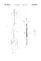
- FIG. 1is a partially longitudinally sectioned view of a first embodiment of the present invention.
- FIG. 2is a partially longitudinally sectioned view of a second embodiment of the present invention.
- FIG. 3is a partially longitudinally sectioned view of a third embodiment of the present invention.
- FIG. 4is a partially longitudinally sectioned view of a fourth embodiment of the present invention.
- FIG. 5is a latitudinally sectioned view taken at A--A in FIGS. 1, 2 and 3.
- FIG. 6is a latitudinally sectioned view taken at B--B in FIGS. 1 and 2.
- FIG. 7is a latitudinally sectioned view taken at C--C in FIGS. 1, 2 and 4.
- FIG. 8is a latitudinally sectioned view taken at D--D in FIG. 4.
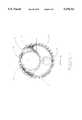
- FIG. 9is a latitudinally sectioned view taken at E--E in FIG. 3.
- catheter 10includes a metallic tube 11 (also referred to as a hypotube) with a manifold 25 and strain relief 26 connected to its proximal end.
- the manifold 25provides a means to connect the catheter 10 to an inflation device (not shown).
- Strain relief 26reduces the propensity for the proximal end of the metallic tube 11 to kink during handling.
- the metallic tube 11is preferably PTFE-coated and includes proximal shaft marks 27 to indicate the position of the distal end of the catheter 10 relative to the proximal end of the guide catheter (not shown).
- Core wire 14is connected to the distal end of the metallic tube 11.
- the distal polymer tube 13is also connected to the distal end of the metallic tube 11 and extends partially over the core wire 14.
- the distal end of the distal polymer tube 13is connected to the proximal balloon waist 18 of the balloon 16.
- Catheter 10further includes a polymer guide wire tube 12 which is connected at its distal end to the distal balloon waist 17.
- the polymer guide wire tube 12extends proximally through the balloon and extends exteriorly along the distal polymer tube 13 and the metallic tube 11.
- the distal polymer tube 13is crimped into a crescent shape at the proximal balloon waist 18 to facilitate passage of the guide wire tube 12 therethrough (as best shown in FIG. 5).
- a radiopaque marker band 15is disposed about the polymer guide wire tube 12 at a position centered within the balloon 16. The radiopaque marker band 15 facilitates fluoroscopic positioning of the balloon catheter at the desired internal vascular site.
- the core wire 14is connected at its distal end between the radiopaque marker band 15 and the polymer and guide wire tube 12 to facilitate longitudinal transmission of force between the distal end of the metallic tube 11 and the distal end of the catheter 10 and in particular, the balloon 16.
- Catheter 10further includes an inflation lumen 51 as best seen in FIGS. 5, 6 and 7.
- the inflation lumen 51allows for the passage of inflation fluid from the manifold 25 to the balloon 16 by way of metallic tube 11 and distal polymer tube 13.
- the polymer guide wire tube 12includes a guide wire lumen 50 as best seen in FIGS. 5, 6 and 7.
- the guide wire lumen 50allows for passage of a guide wire (not shown) which facilitates navigation of the catheter 10 into the vascular system.
- the catheter 10has a relatively short section where the guide wire tube 12 extends coaxially with the balloon 16 and in particular the proximal balloon waist 18.
- the length of the coaxial sectionmay vary depending on the desired performance characteristics.
- the coaxial sectionmay be substantially as shown in U.S. Pat. No. 5,156,594 to Keith et al.
- the catheter shown in Keith '594does not include a parallel lumen proximal section like the present invention, but the distal section of the Keith '594 catheter may be used in combination with the proximal shaft section of the present invention in order to provide a longer coaxial section distally.
- the length of the coaxial sectionmay be between the length which is disclosed in Keith '594 and the length disclosed in the present application. Incorporating a distal coaxial section of a different length does not compromise the benefits provided by the present invention.
- Metallic tube 11is preferably made of 304 V Stainless Steel and includes a PTFE coating on its exterior surface.
- the proximal portion of metallic tube 11 where manifold 25 and strain relief 26 are connectedis preferably left uncoated to facilitate proper adhesive connection.
- the distal end of metallic tube 11is left uncoated to facilitate proper adhesive connection to distal polymer tube 13 and proper weld or solder connection to core wire 14.
- proximal shaft marks 27are formed by masking portions of the metallic tube 11 prior to PTFE coating.
- Metallic tube 11preferably has an outside diameter of 0.024 inches, an inside diameter of 0.017 inches and an overall length of 110 cm. Proximal shaft marks 27 are placed at 90 cm and 100 cm from the distal end of the catheter 10.
- Proximal shaft marks 27preferably have a length of between 0.5 cm and 1.0 cm.
- Metallic tube 11may be stress-relieved by exposing the metallic tube 11 to a temperature of about 725 degrees Fahrenheit for a period of about an hour.
- the above exemplary combination of materials, dimensions and processingis designed to provide a metallic tube 11 which can sustain aggressive handling without damage.
- the metallic tube 11can be bent in an 8-inch diameter loop without sustaining permanent deformation.
- suitable materials, dimensions and manufacturing processesmay be employed to meet the design requirements.
- Manifold 25 and strain relief 26are connected to the proximal end of metallic tube 11 by a suitable medical grade adhesive such as a urethane or an epoxy adhesive.
- Manifold 25is preferably made of polycarbonate and is injection molded.
- Strain relief 26is preferably made of a polyolefin such as a polyolefin copolymer or high density polyethylene and is preferably made by an extrusion process.
- Manifold 25includes standard lure threads at the proximal end to facilitate fluid connection to an inflation device (not shown). Those skilled in the art will recognize that other suitable manifolds and strain reliefs may be employed to accomplish the same tasks.
- Polymer guide wire tube 12is preferably made of an extruded polymer such as high density polyethylene but may also be made of a thermoset polymer such as polyimide.
- Polymer guide wire tube 12may include an exterior lubricious coating such as PTFE or a silicone based coating and may also include an internal coating to reduce the friction between the inside surface of the polymer guide wire tube 12 and the exterior surface of a guide wire (not shown).
- the polymer guide wire tube 12is connected at its distal end to the distal balloon waste 17 of the balloon 16 by means of a suitable adhesive such as cyanoacrylate or epoxy. As best seen in FIG.
- the polymer guide wire tube 12is nested in the crimp of distal polymer tube 13 with the proximal balloon waste 18 surrounding both the polymer guide wire tube 12 and the distal polymer tube 13.
- a suitable adhesive 19is used to create a mechanical and fluid seal around the polymer guide wire tube 12.
- the polymer guide wire tube 12extends adjacent the distal polymer tube 13 and the metallic tube 11.
- the polymer guide wire tube 12may be connected to either or both the metallic tube 11 and the distal polymer tube 13 by means of a suitable adhesive. Alternatively, polymer guide wire tube 12 may remain unconnected to either the metallic tube 11 or the distal polymer tube 13.
- Core wire 14is connected to the distal end of the metallic tube 11 by means of a suitable weld joint or solder joint.
- a short longitudinal slotis made in the distal end of the metallic tube 11 to facilitate connection of guide wire 14.
- the slotis preferably a width slightly smaller than the diameter of the proximal end of the core wire 14.
- core wire 14may be connected inside the lumen of metallic tube 11 in an off-axis position, thus allowing for the passage of inflation fluid without substantially increasing the profile at the junction point.
- Core wire 14is preferably made of 304 V stainless steel and includes a series of tapers along its length made by a suitable process such as centerless grinding.
- the distal end of the core wire 14may be stamp-formed into a ribbon to facilitate insertion between the marker band 15 and the polymer guide wire tube 12 under the balloon.
- a suitable adhesivesuch as cyanoacrylate facilitates connection between the distal end of the core wire 14 and the marker band 15.
- Core wire 14is preferably 0.012" diameter at the proximal end and may taper to approximately 0.005" diameter adjacent the proximal balloon waste 18.
- the overall length of core wire 14is preferably about 9"-12".
- Distal polymer tube 13is preferably made of a polyolefin such as high density polyethylene, but may also be made of other suitable materials such as a thermoset polymer (e.g., polyimide).
- the distal polymer tubeis preferably made by an extrusion process and may incorporate tapers along its length formed by pulling the extruded tube through a heated die. The crimp in the distal end of the distal polymer tube 13 may be formed by inserting the distal end of the tube 13 into a slot and partially compressing the tube radially with a rounded blade.
- suitable materials, dimensions and manufacturing processesmay be employed.
- the inflatable balloon 16is preferably made of a polyolefin such as a polyolefin copolymer and is formed by blow-molding an extruded and irradiated tube.
- a polyolefinsuch as a polyolefin copolymer
- Other suitable materialssuch as PET, nylon and HDPE may be employed to manufacture the balloon 16.
- Radiopaque marker band 15is preferably made of a metallic alloy such as 90% platinum, 10% iridium and is bonded to the distal end of the polymer guide wire tube 12 by a suitable adhesive such as cyanoacrylate.
- the radiopaque marker bandpreferably has a length of 0.051" and inside diameter of preferably about 0.022" and a wall thickness of preferably about 0.003".
- suitable materialssuch as gold, and other suitable dimensions may be employed.
- Catheter 20may incorporate a series of connection rings 21.
- the connection rings 21serve to connect the polymer guide wire tube 12 to the distal polymer tube 13 and the metallic tube 11.
- the connection rings 21ultimately function to guide the catheter 20 substantially parallel to a guide wire (not shown) inserted into the polymer guide wire tube 12. This may serve to enhance the navigability and crossability of the catheter 20.
- Connection rings 21may be made of any suitable thin walled polymer tube section such as polyethylene, polyolefin or polyimide, but a heat-shrinkable polymer is preferred.
- Connection rings 21may be secured to the polymer guide wire tube 12, the distal polymer tube 13 and the metallic tube 11 by a suitable adhesive such as cyanoacrylate. Although adhesive is preferred to secure the connection rings 21 along the catheter shaft, adhesive may not be necessary if the one wishes to be able to move the connection rings 21 or if the connection rings 21 sufficiently secure due to friction. Preferably, the connection rings 21 do not substantially add to the overall profile of the catheter 20.
- the connection rings 21are preferably on the order of 0.25 inches long but may range between 0.0625 and 0.50 inches long.
- the connection rings 21are preferably spaced 1.0 inch apart but may be placed closer together or further apart as deemed necessary.
- Catheter 30may incorporate a connection sleeve 31 to secure the polymer guide wire tube 12 to the metallic tube 11 and the distal polymer tube 13.
- the connection sleeve 31serves substantially the same function of connection rings 21 as discussed with reference to FIG. 2.
- Connection sleeve 31is preferably made of a heat-shrinkable polymer such as irradiated polyolefin and is heat-shrunk around the catheter shaft to substantially conform to the outer profile of the catheter 30, as best seen in the cross-sectional drawing shown in FIG. 9 taken at section E--E in FIG. 3.
- connection sleeve 31may be made of several different materials.
- connection sleeve 31may be a single elongate piece or a plurality of pieces spaced along the catheter shaft.
- a suitable adhesivesuch as a cyanoacrylate may be employed to secure the connection sleeve 31 to the catheter shaft.
- the distal end of the connection sleeve 31is preferably sealed to the catheter shaft with adhesive to prevent bodily fluids such as blood from flowing under the sleeve 31.
- Catheter 40incorporates a dual lumen extruded tube to comprise a distal polymer extrusion 41 and a skived extrusion guide wire tube 42.
- the dual lumen extrusion of catheter 40replaces the two separate tubes comprising the distal polymer tube 13 and polymer guide wire tube 12 as discussed with reference to FIG. 1.
- the dual lumen extrusionnegates the need to provide connection rings or a connection sleeve on the distal end of the catheter 40.
- the distal polymer extrusion 41includes a guide wire lumen 50 and an inflation lumen 51 with core wire 14 extending therethrough, as best shown in FIG. 8.
- the skived extrusion guide wire tube 42is made by cutting away the portion of the dual lumen extrusion comprising the inflation lumen 51.
- the skived extrusion guide wire tube 42may be connected to the metallic tube 11 by a suitable adhesive, by connection rings 21, or by connection sleeve 31 as discussed with reference to FIGS. 2 and 3, respectively. It should be noted however, that a connection between the skived extrusion guide wire tube 42 and the metallic tube 11 is not absolutely necessary but may be desirable depending on the functional characteristics desired.
- the catheter 10, 20, 30 or 40is preferably used in a manner similar to that of a conventional OTW catheter, while making the necessary handling adjustments due to the enhanced performance characteristics described previously.
Landscapes
- Health & Medical Sciences (AREA)
- Life Sciences & Earth Sciences (AREA)
- Heart & Thoracic Surgery (AREA)
- Hematology (AREA)
- Engineering & Computer Science (AREA)
- Anesthesiology (AREA)
- Biomedical Technology (AREA)
- Pulmonology (AREA)
- Biophysics (AREA)
- Animal Behavior & Ethology (AREA)
- General Health & Medical Sciences (AREA)
- Public Health (AREA)
- Veterinary Medicine (AREA)
- Vascular Medicine (AREA)
- Child & Adolescent Psychology (AREA)
- Media Introduction/Drainage Providing Device (AREA)
Abstract
Description
The subject matter of this application is related to the disclosure in commonly assigned and co-pending U.S. patent application entitled INTRAVASCULAR CATHETER WITH DISTAL GUIDE WIRE LUMEN AND TRANSITION MEMBER filed Feb. 16, 1994 Ser. No. 08/197,169 which is hereby fully incorporated by reference.
The present invention generally relates to intravascular catheters. More specifically, the present invention relates to over-the-wire type balloon catheters. Those skilled in the art will recognize the benefits of applying the present invention to similar fields not discussed herein.
Intravascular diseases are commonly treated by relatively non-invasive techniques such as percutaneous translumenal angioplasty (PTA) and percutaneous translumenal coronary angioplasty (PTCA). These therapeutic techniques are well known in the art and may typically involve the use of a balloon catheter and a guide wire, possibly in combination with other intravascular devices. The balloon catheter is advanced over the guide wire such that the distal end of the balloon catheter is positioned adjacent a restriction in a diseased vessel. The balloon is inflated and the restriction in the vessel is thus opened.
Balloon catheters are commonly categorized into three main types according to their guide wire compatibility; over-the-wire (OTW), fixed-wire (FW), and single-operator-exchange (SOE). OTW, FW, and SOE as used hereinafter refers to the conventional design of such catheters. Examples of OTW, FW and SOE catheters may be found in U.S. Pat. Nos. 5,047,045 to Arney et al., 4,943,278 to Euteneuer et al., and 5,156,594 to Keith et al., respectively. The entire disclosure of the above listed patents is hereby incorporated by reference.
OTW catheters are used in combination with a guide wire which is removably insertable therein. The guide wire extends through a full length guide wire lumen inside the OTW catheter. As such, distal pressure measurements, distal fluid injections, and guide wire exchanges may be facilitated through the guide wire lumen. OTW catheter exchanges may be facilitated by the use of an extension wire or a guide wire captivation device.
SOE catheters are also used in combination with a guide wire, but the guide wire extends through a distal guide wire lumen which is inside only a distal portion of the catheter and the remainder of the guide wire remains exposed outside the catheter. As such, a SOE catheter may be readily exchanged over a conventional length guide wire. However, SOE catheters do not readily provide a conventional means to exchange a guide wire without the use of ancillary equipment. Furthermore, SOE catheters do not provide a conventional means for distal pressure measurement and/or distal fluid injection.
By contrast, FW catheters are typically used without a guide wire and as such have a relatively small profile. FW catheters incorporate a built-in core wire which serves some of the same functions as a guide wire. The core wire, however, is not removable and thus the FW catheter is not exchangeable over the core wire. In addition, FW catheters do not provide a conventional means for distal pressure measurement and distal fluid injection.
Although FW catheters generally provide an advantage in profile and although SOE catheters generally provide an advantage in rapid catheter exchange, OTW catheters are considered the more versatile of the group and as such are favored for the majority of clinical applications.
In terms of catheter shaft construction, the proximal shaft portion of an OTW catheter must be designed to contain the guide wire and also provide a path for inflation fluid to inflate the distally located balloon. Thus, the proximal shaft portion of an OTW balloon catheter includes a guide wire lumen and an inflation lumen. By contrast, both SOE catheters and FW catheters only include an inflation lumen in the proximal portion of the shaft. SOE catheters do not require a guide wire lumen in the proximal portion of the shaft because the guide wire is external to the proximal catheter shaft. FW catheters do not require a guide wire lumen in the proximal portion of the shaft because FW catheters are not constructed to be used with removable guide wires. Since the proximal shaft portion of an OTW catheter must accommodate a guide wire lumen and since FW and SOE catheters do not need to accommodate a guide wire lumen, the profile (outside diameter) of the proximal shaft of an OTW catheter is inherently larger than the profile of either a FW or SOE catheter.
In addition to the inherent profile requirements discussed above, the optimal design of a proximal shaft section of an OTW balloon catheter must account for other performance criteria. For example, it is desirable to have a proximal shaft section which is the smallest possible profile, highly pushable (i.e. longitudinally stiff) yet easily coiled for temporary storage and resistant to damage resulting from in-vitro handling (i.e., latitudinally flexible). High performance FW and SOE catheters typically utilize a metallic proximal shaft section (commonly referred to as a hypotube) with an outside diameter on the order of 0.032 inches and a wall thickness on the order of 0.003 inches. Practicing physicians have found the profile, pushability, ease of handling and other performance aspects of these hypotube-type FW and SOE catheters superior by comparison to non-hypotube-type FW and SOE catheters. Similarly, OTW catheters which utilize a hypotube for a proximal shaft section provide enhanced pushability with low profile. However, since the profile of an OTW catheter is inherently larger than a FW or SOE catheter, the latitudinal stiffness of an OTW catheter utilizing a hypotube proximal shaft is undesirably high. As such, the hypotube shaft on an OTW catheter tends to be more difficult to manage in-vitro and more prone to damage during handling.
In view of the advantages of a metallic proximal shaft section and in view of the advantages of an OTW catheter design discussed earlier, it is desirable to have an OTW catheter with a metallic proximal shaft section which is easy to manipulate in-vivo, easy to manage and resistant to damage from in-vitro handling.
The present invention overcomes the competing disadvantages of the prior art in a novel and non-obvious manner, to provide a catheter that, for example, is easy to manipulate in-vivo, easy to manage and resistant to damage in-vitro. One embodiment of the present invention is a balloon dilation catheter system, including a proximal metallic tube, a polymer guide wire tube extending exteriorly and parallel with the metallic tube, the polymer guide wire tube having a guide wire lumen extending therethrough, a distal polymer tube extending exteriorly and parallel with the polymer guide wire tube, the proximal end of the distal polymer tube connected to the distal end of the proximal metallic tube, a balloon having a proximal end sealably connected to the distal end of the distal polymer tube, the distal end of the balloon sealably connected to the distal end of the polymer guide wire tube, and a removable guide wire slidably disposed in and extending through the guide wire lumen of the polymer guide wire tube.
In another embodiment of the present invention, the proximal end of the balloon is sealably connected to both the distal end of the distal polymer tube and a distal portion of the polymer guide wire tube.
In another embodiment of the present invention, the catheter further includes a core wire having a proximal end rigidly secured to the distal end of the metallic tube. The core wire may extend through the distal polymer tube. In addition, the distal end of the core wire may be connected to one or more of the polymer guide wire tube, the distal polymer tube, and the balloon.
A further embodiment of the present invention includes a proximal sleeve disposed about and connecting the polymer guide wire tube and the metallic tube.
In another embodiment of the present invention, the polymer guide wire tube is a dual-lumen extrusion which includes a connection lumen with the metallic tube extending through the connection lumen.
In a further embodiment of the present invention, the distal polymer tube and the polymer guide wire tube are integrally formed as a dual-lumen extrusion.
While the disclosure focuses on OTW balloon catheters, one skilled in the art will recognize that invention may be incorporated into other devices and uses not discussed herein. Furthermore, in addition to the advantages described, other advantages of the present invention may be appreciated without departing from the spirit of the invention.
FIG. 1 is a partially longitudinally sectioned view of a first embodiment of the present invention.
FIG. 2 is a partially longitudinally sectioned view of a second embodiment of the present invention.
FIG. 3 is a partially longitudinally sectioned view of a third embodiment of the present invention.
FIG. 4 is a partially longitudinally sectioned view of a fourth embodiment of the present invention.
FIG. 5 is a latitudinally sectioned view taken at A--A in FIGS. 1, 2 and 3.
FIG. 6 is a latitudinally sectioned view taken at B--B in FIGS. 1 and 2.
FIG. 7 is a latitudinally sectioned view taken at C--C in FIGS. 1, 2 and 4.
FIG. 8 is a latitudinally sectioned view taken at D--D in FIG. 4.
FIG. 9 is a latitudinally sectioned view taken at E--E in FIG. 3.
The following detailed description should be read with reference to the drawings in which like elements in different figures are numbered identically.
Referring to FIG. 1,catheter 10 includes a metallic tube 11 (also referred to as a hypotube) with a manifold 25 andstrain relief 26 connected to its proximal end. The manifold 25 provides a means to connect thecatheter 10 to an inflation device (not shown).Strain relief 26 reduces the propensity for the proximal end of themetallic tube 11 to kink during handling. Themetallic tube 11 is preferably PTFE-coated and includes proximal shaft marks 27 to indicate the position of the distal end of thecatheter 10 relative to the proximal end of the guide catheter (not shown).Core wire 14 is connected to the distal end of themetallic tube 11. Thedistal polymer tube 13 is also connected to the distal end of themetallic tube 11 and extends partially over thecore wire 14. The distal end of thedistal polymer tube 13 is connected to theproximal balloon waist 18 of theballoon 16.Catheter 10 further includes a polymerguide wire tube 12 which is connected at its distal end to thedistal balloon waist 17. The polymerguide wire tube 12 extends proximally through the balloon and extends exteriorly along thedistal polymer tube 13 and themetallic tube 11. Thedistal polymer tube 13 is crimped into a crescent shape at theproximal balloon waist 18 to facilitate passage of theguide wire tube 12 therethrough (as best shown in FIG. 5). Aradiopaque marker band 15 is disposed about the polymerguide wire tube 12 at a position centered within theballoon 16. Theradiopaque marker band 15 facilitates fluoroscopic positioning of the balloon catheter at the desired internal vascular site. Thecore wire 14 is connected at its distal end between theradiopaque marker band 15 and the polymer and guidewire tube 12 to facilitate longitudinal transmission of force between the distal end of themetallic tube 11 and the distal end of thecatheter 10 and in particular, theballoon 16.Catheter 10 further includes aninflation lumen 51 as best seen in FIGS. 5, 6 and 7. Theinflation lumen 51 allows for the passage of inflation fluid from the manifold 25 to theballoon 16 by way ofmetallic tube 11 anddistal polymer tube 13. The polymerguide wire tube 12 includes aguide wire lumen 50 as best seen in FIGS. 5, 6 and 7. Theguide wire lumen 50 allows for passage of a guide wire (not shown) which facilitates navigation of thecatheter 10 into the vascular system.
Continuing to refer to FIG. 1, thecatheter 10 has a relatively short section where theguide wire tube 12 extends coaxially with theballoon 16 and in particular theproximal balloon waist 18. It should be noted however that the length of the coaxial section may vary depending on the desired performance characteristics. For example, the coaxial section may be substantially as shown in U.S. Pat. No. 5,156,594 to Keith et al. The catheter shown in Keith '594 does not include a parallel lumen proximal section like the present invention, but the distal section of the Keith '594 catheter may be used in combination with the proximal shaft section of the present invention in order to provide a longer coaxial section distally. In addition, the length of the coaxial section may be between the length which is disclosed in Keith '594 and the length disclosed in the present application. Incorporating a distal coaxial section of a different length does not compromise the benefits provided by the present invention.
Polymerguide wire tube 12 is preferably made of an extruded polymer such as high density polyethylene but may also be made of a thermoset polymer such as polyimide. Polymerguide wire tube 12 may include an exterior lubricious coating such as PTFE or a silicone based coating and may also include an internal coating to reduce the friction between the inside surface of the polymerguide wire tube 12 and the exterior surface of a guide wire (not shown). The polymerguide wire tube 12 is connected at its distal end to thedistal balloon waste 17 of theballoon 16 by means of a suitable adhesive such as cyanoacrylate or epoxy. As best seen in FIG. 5, the polymerguide wire tube 12 is nested in the crimp ofdistal polymer tube 13 with theproximal balloon waste 18 surrounding both the polymerguide wire tube 12 and thedistal polymer tube 13. Asuitable adhesive 19 is used to create a mechanical and fluid seal around the polymerguide wire tube 12. The polymerguide wire tube 12 extends adjacent thedistal polymer tube 13 and themetallic tube 11. The polymerguide wire tube 12 may be connected to either or both themetallic tube 11 and thedistal polymer tube 13 by means of a suitable adhesive. Alternatively, polymerguide wire tube 12 may remain unconnected to either themetallic tube 11 or thedistal polymer tube 13.
Theinflatable balloon 16 is preferably made of a polyolefin such as a polyolefin copolymer and is formed by blow-molding an extruded and irradiated tube. Other suitable materials such as PET, nylon and HDPE may be employed to manufacture theballoon 16.
Referring now to FIG. 2, a second embodiment of the present invention is shown. The above discussion with reference to FIG. 1 is equally applicable to FIG. 2 with the following exceptions.Catheter 20 may incorporate a series of connection rings 21. The connection rings 21 serve to connect the polymerguide wire tube 12 to thedistal polymer tube 13 and themetallic tube 11. The connection rings 21 ultimately function to guide thecatheter 20 substantially parallel to a guide wire (not shown) inserted into the polymerguide wire tube 12. This may serve to enhance the navigability and crossability of thecatheter 20. Connection rings 21 may be made of any suitable thin walled polymer tube section such as polyethylene, polyolefin or polyimide, but a heat-shrinkable polymer is preferred. Connection rings 21 may be secured to the polymerguide wire tube 12, thedistal polymer tube 13 and themetallic tube 11 by a suitable adhesive such as cyanoacrylate. Although adhesive is preferred to secure the connection rings 21 along the catheter shaft, adhesive may not be necessary if the one wishes to be able to move the connection rings 21 or if the connection rings 21 sufficiently secure due to friction. Preferably, the connection rings 21 do not substantially add to the overall profile of thecatheter 20. The connection rings 21 are preferably on the order of 0.25 inches long but may range between 0.0625 and 0.50 inches long. The connection rings 21 are preferably spaced 1.0 inch apart but may be placed closer together or further apart as deemed necessary.
Referring now to FIG. 3, a third embodiment of the present invention is shown. The above discussion with reference to FIG. 1 is equally applicable to FIG. 3 with the following exceptions. Catheter 30 may incorporate aconnection sleeve 31 to secure the polymerguide wire tube 12 to themetallic tube 11 and thedistal polymer tube 13. Theconnection sleeve 31 serves substantially the same function of connection rings 21 as discussed with reference to FIG. 2.Connection sleeve 31 is preferably made of a heat-shrinkable polymer such as irradiated polyolefin and is heat-shrunk around the catheter shaft to substantially conform to the outer profile of the catheter 30, as best seen in the cross-sectional drawing shown in FIG. 9 taken at section E--E in FIG. 3. As with the connection rings 21 referred to in FIG. 2, theconnection sleeve 31 may be made of several different materials. In addition, theconnection sleeve 31 may be a single elongate piece or a plurality of pieces spaced along the catheter shaft. A suitable adhesive such as a cyanoacrylate may be employed to secure theconnection sleeve 31 to the catheter shaft. The distal end of theconnection sleeve 31 is preferably sealed to the catheter shaft with adhesive to prevent bodily fluids such as blood from flowing under thesleeve 31.
Referring now to FIG. 4, a fourth embodiment of the present invention is shown. The above discussion with reference to FIG. 1 is equally applicable to FIG. 4 with the following exceptions. Catheter 40 incorporates a dual lumen extruded tube to comprise adistal polymer extrusion 41 and a skived extrusionguide wire tube 42. The dual lumen extrusion of catheter 40 replaces the two separate tubes comprising thedistal polymer tube 13 and polymerguide wire tube 12 as discussed with reference to FIG. 1. The dual lumen extrusion negates the need to provide connection rings or a connection sleeve on the distal end of the catheter 40. Thedistal polymer extrusion 41 includes aguide wire lumen 50 and aninflation lumen 51 withcore wire 14 extending therethrough, as best shown in FIG. 8. The skived extrusionguide wire tube 42 is made by cutting away the portion of the dual lumen extrusion comprising theinflation lumen 51. The skived extrusionguide wire tube 42 may be connected to themetallic tube 11 by a suitable adhesive, by connection rings 21, or byconnection sleeve 31 as discussed with reference to FIGS. 2 and 3, respectively. It should be noted however, that a connection between the skived extrusionguide wire tube 42 and themetallic tube 11 is not absolutely necessary but may be desirable depending on the functional characteristics desired.
In practice, thecatheter
While the specification describes the preferred constructions, methods and materials of manufacture and methods of practice, those skilled in the art will appreciate the scope and spirit of the invention with reference to the appended claims.
Claims (15)
1. A balloon dilation catheter system, comprising:
(i) a metallic tube having a proximal end, a distal end, and a proximal inflation lumen extending therethrough;
(ii) a polymer guide wire tube having a proximal end, a distal end, an exterior surface, and a guide wire lumen extending therethrough, the polymer guide wire tube extending exteriorly and parallel with the metallic tube, the proximal end of the polymer guide wire tube extending proximally to a point near the proximal end of the metallic tube, the distal end of the polymer guide wire tube extending distally beyond the distal end of the metallic tube;
(iii) a core wire having a proximal end and a distal end, the proximal end of the core wire rigidly secured to the distal end of the metallic tube;
(iv) a distal polymer tube having a proximal end, a distal end, and a distal inflation lumen extending therethrough, the distal polymer tube extending exteriorly and parallel with the polymer guide wire tube, the proximal end of the distal polymer tube connected to the distal end of the proximal metallic tube, a portion of the distal polymer tube connected to a portion of the polymer guide wire tube, the distal inflation lumen fluidly communicating with the proximal inflation lumen;
(v) a balloon having a proximal end, a distal end, and a balloon inflation lumen extending therethrough, the proximal end of the balloon sealably connected to both the distal end of the distal polymer tube and a distal portion of the polymer guide wire tube, the distal end of the balloon sealably connected to the distal end of the polymer guide wire tube, the balloon inflation lumen fluidly communicating with the distal inflation lumen; and
(vi) a removable guide wire slidably disposed in and extending through the guide wire lumen of the polymer guide wire tube.
2. A balloon dilation catheter system as in claim 1, further comprising a proximal sleeve disposed about and connecting the polymer guide wire tube and the metallic tube.
3. A balloon dilation catheter system as in claim 1, wherein the polymer guide wire tube is a dual-lumen extrusion further including a connection lumen extending therethrough, the metallic tube extending into the connection lumen.
4. A balloon dilation catheter as in claim 1, wherein the distal polymer tube and the polymer guide wire tube are integrally formed as a dual-lumen extrusion.
5. A balloon dilation catheter as in claim 1, wherein the distal end of the core wire is connected to one of the polymer guide wire tube, the distal polymer tube, and the balloon.
6. A balloon dilation catheter system, comprising:
(i) a metallic tube having a proximal end, a distal end, an exterior surface, and a proximal inflation lumen extending therethrough;
(ii) a polymer guide wire tube having a proximal end, a distal end, an exterior surface, and a guide wire lumen extending therethrough, the polymer guide wire tube extending exteriorly and parallel with the metallic tube, the proximal end of the polymer guide wire tube extending proximally to a point near the proximal end of the metallic tube, the distal end of the polymer guide wire tube extending distally beyond the distal end of the metallic tube;
(iii) a distal polymer tube having a proximal end, a distal end, an exterior surface, and a distal inflation lumen extending therethrough, the distal polymer tube extending exteriorly and parallel with the polymer guide wire tube, the proximal end of the distal polymer tube connected to the distal end of the proximal metallic tube, a portion of the exterior surface of the distal polymer tube connected to a portion of the exterior surface of the polymer guide wire tube, the distal inflation lumen fluidly communicating with the proximal inflation lumen;
(iv) a balloon having a proximal end, a distal end, and a balloon inflation lumen extending therethrough, the proximal end of the balloon sealably connected to both the distal end of the distal polymer tube and a distal portion of the polymer guide wire tube, the distal end of the balloon sealably connected to the distal end of the polymer guide wire tube, the balloon inflation lumen fluidly communicating with the distal inflation lumen; and
(v) a removable guide wire slidably disposed in and extending through the guide wire lumen of the polymer guide wire tube.
7. A balloon dilation catheter system as in claim 6, further comprising a proximal sleeve disposed about and connecting the polymer guide wire tube and the metallic tube.
8. A balloon dilation catheter system as in claim 6, wherein the polymer guide wire tube is a dual-lumen extrusion further including a connection lumen extending therethrough, the metallic tube extending through the connection lumen.
9. A balloon dilation catheter as in claim 6, wherein the distal polymer tube and the polymer guide wire tube are integrally formed as a dual-lumen extrusion.
10. A balloon dilation catheter system, comprising:
(i) a metallic tube having a proximal end, a distal end, an exterior surface, and a proximal inflation lumen extending therethrough;
(ii) a polymer guide wire tube having a proximal end, a distal end, an exterior surface, and a guide wire lumen extending therethrough, the polymer guide wire tube extending exteriorly and parallel with the metallic tube, the proximal end of the polymer guide wire tube extending proximally to a point near the proximal end of the metallic tube, the distal end of the polymer guide wire tube extending distally beyond the distal end of the metallic tube;
(iii) a distal polymer tube having a proximal end, a distal end, an exterior surface, and a distal inflation lumen extending therethrough, the distal polymer tube extending exteriorly and parallel with the polymer guide wire tube, the proximal end of the distal polymer tube connected to the distal end of the proximal metallic tube, a portion of the exterior surface of the distal polymer tube connected to a portion of the exterior surface of the polymer guide wire tube, the distal inflation lumen fluidly communicating with the proximal inflation lumen;
(iv) a balloon having a proximal end, a distal end, and a balloon inflation lumen extending therethrough, the proximal end of the balloon sealably connected to the distal end of the distal polymer tube, the distal end of the balloon sealably connected to the distal end of the polymer guide wire tube, the balloon inflation lumen fluidly communicating with the distal inflation lumen; and
(v) a removable guide wire slidably disposed in and extending through the guide wire lumen of the polymer guide wire tube.
11. A balloon dilation catheter system as in claim 10, further comprising a proximal sleeve disposed about and connecting the polymer guide wire tube and the metallic tube.
12. A balloon dilation catheter system as in claim 10, wherein the polymer guide wire tube is a dual-lumen extrusion further including a connection lumen extending therethrough, the metallic tube extending through the connection lumen.
13. A balloon dilation catheter as in claim 10, wherein the distal polymer tube and the polymer guide wire tube are integrally formed as a dual-lumen extrusion.
14. A balloon dilation catheter as in claim 10, wherein the polymer guide wire tube and a proximal waist portion of the balloon extend coaxially.
15. A balloon dilation catheter as in claim 10, wherein a distal portion of the polymer guide wire tube and a distal portion of the distal polymer tube extend coaxially.
Priority Applications (1)
| Application Number | Priority Date | Filing Date | Title |
|---|---|---|---|
| US08/309,240US5470315A (en) | 1994-09-20 | 1994-09-20 | Over-the-wire type balloon catheter with proximal hypotube |
Applications Claiming Priority (1)
| Application Number | Priority Date | Filing Date | Title |
|---|---|---|---|
| US08/309,240US5470315A (en) | 1994-09-20 | 1994-09-20 | Over-the-wire type balloon catheter with proximal hypotube |
Publications (1)
| Publication Number | Publication Date |
|---|---|
| US5470315Atrue US5470315A (en) | 1995-11-28 |
Family
ID=23197338
Family Applications (1)
| Application Number | Title | Priority Date | Filing Date |
|---|---|---|---|
| US08/309,240Expired - LifetimeUS5470315A (en) | 1994-09-20 | 1994-09-20 | Over-the-wire type balloon catheter with proximal hypotube |
Country Status (1)
| Country | Link |
|---|---|
| US (1) | US5470315A (en) |
Cited By (75)
| Publication number | Priority date | Publication date | Assignee | Title |
|---|---|---|---|---|
| US5868706A (en)* | 1994-12-27 | 1999-02-09 | Advanced Cardiovascular Systems, Inc. | Catheter with reinforced oblong transverse cross section |
| US6179811B1 (en) | 1997-11-25 | 2001-01-30 | Medtronic, Inc. | Imbedded marker and flexible guide wire shaft |
| US6190358B1 (en)* | 1995-02-24 | 2001-02-20 | Medtronic Ave, Inc. | Reinforced rapid exchange balloon catheter |
| US6322534B1 (en) | 1998-11-07 | 2001-11-27 | Cordis Corporation | Variable stiffness balloon catheter |
| US6340368B1 (en) | 1998-10-23 | 2002-01-22 | Medtronic Inc. | Implantable device with radiopaque ends |
| US6355016B1 (en)* | 1997-03-06 | 2002-03-12 | Medtronic Percusurge, Inc. | Catheter core wire |
| US6361557B1 (en) | 1999-02-05 | 2002-03-26 | Medtronic Ave, Inc. | Staplebutton radiopaque marker |
| US6379365B1 (en) | 1999-03-29 | 2002-04-30 | Alexis Diaz | Stent delivery catheter system having grooved shaft |
| US6475187B1 (en) | 1998-03-04 | 2002-11-05 | Scimed Life Systems, Inc. | Convertible catheter incorporating distal force transfer mechanism |
| US20030055448A1 (en)* | 2001-09-19 | 2003-03-20 | Advanced Cardiovascular Systems, Inc. | Catheter with a polyimide distal tip |
| US6863678B2 (en)* | 2001-09-19 | 2005-03-08 | Advanced Cardiovascular Systems, Inc. | Catheter with a multilayered shaft section having a polyimide layer |
| US20050182475A1 (en)* | 2003-09-02 | 2005-08-18 | Jimmy Jen | Delivery system for a medical device |
| US20050267442A1 (en)* | 2004-05-27 | 2005-12-01 | Randolf Von Oepen | Catheter having main body portion with coil-defined guidewire passage |
| US20060064074A1 (en)* | 2004-09-21 | 2006-03-23 | Scimed Life Systems, Inc. | Rapid exchange catheters having a sealed guidewire lumen and methods of making the same |
| US7118551B1 (en) | 1999-12-22 | 2006-10-10 | Advanced Cardiovascular Systems, Inc. | Non-metal reinforcing mandrel |
| US20070016132A1 (en)* | 2004-05-27 | 2007-01-18 | Oepen Randolf V | Catheter having plurality of stiffening members |
| JP2007501655A (en)* | 2003-08-08 | 2007-02-01 | エクステント・インコーポレーテッド | Apparatus and method for deploying an artificial blood vessel |
| US20070078439A1 (en)* | 2004-05-27 | 2007-04-05 | Axel Grandt | Multiple lumen catheter and method of making same |
| US20070100422A1 (en)* | 2003-09-02 | 2007-05-03 | Shumer Daniel H | Delivery system for a medical device |
| US20070118201A1 (en)* | 2003-09-02 | 2007-05-24 | Pappas Jeffrey M | Delivery system for a medical device |
| US20070151650A1 (en)* | 2002-12-31 | 2007-07-05 | Advanced Cardiovascular Systems, Inc. | Rapid exchange balloon catheter having a reinforced inner tubular member |
| US20070191865A1 (en)* | 2003-09-02 | 2007-08-16 | Pappas Jeffrey M | Delivery System For A Medical Device |
| US20070288036A1 (en)* | 2006-06-09 | 2007-12-13 | Niranjan Seshadri | Assembly for crossing a chronic total occlusion and method therefor |
| US20090105801A1 (en)* | 2007-10-23 | 2009-04-23 | William Cook Europe, Aps | Indwelling catheter arrangement |
| US20090157162A1 (en)* | 2007-10-17 | 2009-06-18 | Mina Chow | Rapid-exchange retractable sheath self-expanding delivery system with incompressible inner member and flexible distal assembly |
| US20090216185A1 (en)* | 2008-02-26 | 2009-08-27 | Boston Scientific Scimed, Inc. | Balloon catheter with durable tip portion |
| US20090248137A1 (en)* | 2001-09-11 | 2009-10-01 | Xtent, Inc. | Expandable stent |
| US7625353B2 (en) | 2004-05-27 | 2009-12-01 | Abbott Laboratories | Catheter having first and second guidewire tubes and overlapping stiffening members |
| US7628769B2 (en) | 2004-05-27 | 2009-12-08 | Abbott Laboratories | Catheter having overlapping stiffening members |
| US20090306685A1 (en)* | 2008-06-10 | 2009-12-10 | Ension, Inc. | Noninvasive trans-catheter method and apparatus for remote suture placement such as for septal defect repair, left atrial appendage closure, pacemaker electrode placement, mitral valve repair, and other inner-cardiac and inner-arterial applications |
| US7658723B2 (en) | 2004-05-27 | 2010-02-09 | Abbott Laboratories | Catheter having plurality of stiffening members |
| US7785439B2 (en) | 2004-09-29 | 2010-08-31 | Abbott Laboratories Vascular Enterprises Limited | Method for connecting a catheter balloon with a catheter shaft of a balloon catheter |
| US7785318B2 (en) | 2004-05-27 | 2010-08-31 | Abbott Laboratories | Catheter having plurality of stiffening members |
| US7794448B2 (en) | 2004-05-27 | 2010-09-14 | Abbott Laboratories | Multiple lumen catheter and method of making same |
| US20100312101A1 (en)* | 2009-06-05 | 2010-12-09 | Entellus Medical, Inc. | Frontal sinus dilation catheter |
| US7906066B2 (en) | 2006-06-30 | 2011-03-15 | Abbott Cardiovascular Systems, Inc. | Method of making a balloon catheter shaft having high strength and flexibility |
| US7918881B2 (en) | 2003-06-09 | 2011-04-05 | Xtent, Inc. | Stent deployment systems and methods |
| US8016871B2 (en) | 2001-12-03 | 2011-09-13 | Xtent, Inc. | Apparatus and methods for delivery of multiple distributed stents |
| US8083788B2 (en) | 2001-12-03 | 2011-12-27 | Xtent, Inc. | Apparatus and methods for positioning prostheses for deployment from a catheter |
| US8177831B2 (en) | 2001-12-03 | 2012-05-15 | Xtent, Inc. | Stent delivery apparatus and method |
| US8282680B2 (en) | 2003-01-17 | 2012-10-09 | J. W. Medical Systems Ltd. | Multiple independent nested stent structures and methods for their preparation and deployment |
| US8317859B2 (en) | 2004-06-28 | 2012-11-27 | J.W. Medical Systems Ltd. | Devices and methods for controlling expandable prostheses during deployment |
| US8323432B2 (en) | 2002-12-31 | 2012-12-04 | Abbott Laboratories Vascular Enterprises Limited | Catheter and method of manufacturing same |
| US8382738B2 (en) | 2006-06-30 | 2013-02-26 | Abbott Cardiovascular Systems, Inc. | Balloon catheter tapered shaft having high strength and flexibility and method of making same |
| US8403885B2 (en) | 2007-12-17 | 2013-03-26 | Abbott Cardiovascular Systems Inc. | Catheter having transitioning shaft segments |
| US8444608B2 (en) | 2008-11-26 | 2013-05-21 | Abbott Cardivascular Systems, Inc. | Robust catheter tubing |
| US8460358B2 (en) | 2004-03-30 | 2013-06-11 | J.W. Medical Systems, Ltd. | Rapid exchange interventional devices and methods |
| USD684258S1 (en)* | 2012-03-29 | 2013-06-11 | Biotronik Ag | Hypotube hub |
| US8486132B2 (en) | 2007-03-22 | 2013-07-16 | J.W. Medical Systems Ltd. | Devices and methods for controlling expandable prostheses during deployment |
| US8500789B2 (en) | 2007-07-11 | 2013-08-06 | C. R. Bard, Inc. | Device for catheter sheath retraction |
| US8574282B2 (en) | 2001-12-03 | 2013-11-05 | J.W. Medical Systems Ltd. | Apparatus and methods for delivery of braided prostheses |
| US8585747B2 (en) | 2003-12-23 | 2013-11-19 | J.W. Medical Systems Ltd. | Devices and methods for controlling and indicating the length of an interventional element |
| US8613722B2 (en) | 2008-11-26 | 2013-12-24 | Abbott Cardiovascular Systems, Inc. | Robust multi-layer balloon |
| US8652198B2 (en) | 2006-03-20 | 2014-02-18 | J.W. Medical Systems Ltd. | Apparatus and methods for deployment of linked prosthetic segments |
| US8684963B2 (en) | 2012-07-05 | 2014-04-01 | Abbott Cardiovascular Systems Inc. | Catheter with a dual lumen monolithic shaft |
| US8702781B2 (en) | 2001-12-03 | 2014-04-22 | J.W. Medical Systems Ltd. | Apparatus and methods for delivery of multiple distributed stents |
| US8808346B2 (en) | 2006-01-13 | 2014-08-19 | C. R. Bard, Inc. | Stent delivery system |
| US8834513B2 (en) | 2009-06-05 | 2014-09-16 | Entellus Medical, Inc. | Method and articles for treating the sinus system |
| US8956398B2 (en) | 2001-12-03 | 2015-02-17 | J.W. Medical Systems Ltd. | Custom length stent apparatus |
| US8980297B2 (en) | 2007-02-20 | 2015-03-17 | J.W. Medical Systems Ltd. | Thermo-mechanically controlled implants and methods of use |
| US8986362B2 (en) | 2004-06-28 | 2015-03-24 | J.W. Medical Systems Ltd. | Devices and methods for controlling expandable prostheses during deployment |
| US9079000B2 (en) | 2011-10-18 | 2015-07-14 | Boston Scientific Scimed, Inc. | Integrated crossing balloon catheter |
| US9101503B2 (en) | 2008-03-06 | 2015-08-11 | J.W. Medical Systems Ltd. | Apparatus having variable strut length and methods of use |
| US9283360B2 (en) | 2011-11-10 | 2016-03-15 | Entellus Medical, Inc. | Methods and devices for treating sinusitis |
| US9486614B2 (en) | 2011-06-29 | 2016-11-08 | Entellus Medical, Inc. | Sinus dilation catheter |
| CN106422031A (en)* | 2015-08-05 | 2017-02-22 | 韦伯斯特生物官能(以色列)有限公司 | Guide wire Luer hub |
| US9801745B2 (en) | 2010-10-21 | 2017-10-31 | C.R. Bard, Inc. | System to deliver a bodily implant |
| US10286190B2 (en) | 2013-12-11 | 2019-05-14 | Cook Medical Technologies Llc | Balloon catheter with dynamic vessel engaging member |
| US10406329B2 (en) | 2011-05-26 | 2019-09-10 | Abbott Cardiovascular Systems, Inc. | Through tip for catheter |
| US10849771B2 (en) | 2011-06-27 | 2020-12-01 | Boston Scientific Scimed, Inc. | Stent delivery systems and methods for making and using stent delivery systems |
| WO2021051051A1 (en) | 2019-09-12 | 2021-03-18 | Free Flow Medical, Inc. | Devices, methods, and systems to treat chronic bronchitis |
| US10993822B2 (en) | 2006-08-07 | 2021-05-04 | C. R. Bard, Inc. | Hand-held actuator device |
| US11026822B2 (en) | 2006-01-13 | 2021-06-08 | C. R. Bard, Inc. | Stent delivery system |
| US11918752B2 (en) | 2021-01-14 | 2024-03-05 | Boston Scientific Scimed, Inc. | Flexible and stretch resistant elongate shaft |
| US12419664B2 (en) | 2019-09-12 | 2025-09-23 | Free Flow Medical, Inc. | Devices, methods, and systems to treat chronic bronchitis |
Citations (16)
| Publication number | Priority date | Publication date | Assignee | Title |
|---|---|---|---|---|
| US4943278A (en)* | 1988-02-29 | 1990-07-24 | Scimed Life Systems, Inc. | Dilatation balloon catheter |
| US4968300A (en)* | 1988-10-05 | 1990-11-06 | Abiomed Limited Partnership | Balloon stretch mechanism |
| US5047045A (en)* | 1989-04-13 | 1991-09-10 | Scimed Life Systems, Inc. | Multi-section coaxial angioplasty catheter |
| US5069673A (en)* | 1990-02-07 | 1991-12-03 | Cordis Corporation | Catheter with double step-down bore |
| US5135535A (en)* | 1991-06-11 | 1992-08-04 | Advanced Cardiovascular Systems, Inc. | Catheter system with catheter and guidewire exchange |
| US5156594A (en)* | 1990-08-28 | 1992-10-20 | Scimed Life Systems, Inc. | Balloon catheter with distal guide wire lumen |
| US5159937A (en)* | 1987-09-30 | 1992-11-03 | Advanced Cardiovascular Systems, Inc. | Steerable dilatation catheter |
| US5201723A (en)* | 1991-08-27 | 1993-04-13 | Cordis Corporation | Inclined side holes in the distal end of a catheter |
| WO1993015786A1 (en)* | 1992-02-10 | 1993-08-19 | Scimed Life Systems, Inc. | Intravascular catheter with distal guide wire lumen |
| US5281203A (en)* | 1991-07-05 | 1994-01-25 | Scimed Life Systems, Inc. | Guide wire and sheath for single operator exchange |
| US5290247A (en)* | 1991-05-21 | 1994-03-01 | C. R. Bard, Inc. | Intracoronary exchange apparatus and method |
| US5334147A (en)* | 1993-04-28 | 1994-08-02 | Cordis Corporation | Rapid exchange type dilatation catheter |
| US5370615A (en)* | 1992-12-28 | 1994-12-06 | Cordis Corporation | Balloon catheter for angioplasty |
| US5383890A (en)* | 1993-10-27 | 1995-01-24 | Baxter International Inc. | Low-profile single-lumen perfusion balloon catheter |
| US5403339A (en)* | 1991-06-21 | 1995-04-04 | Terumo Kabushiki Kaisha | Blood vessel dilator |
| US5409470A (en)* | 1993-05-07 | 1995-04-25 | C. R. Bard, Inc. | Dilatation catheter and guidewire with threaded tip connection |
- 1994
- 1994-09-20USUS08/309,240patent/US5470315A/ennot_activeExpired - Lifetime
Patent Citations (16)
| Publication number | Priority date | Publication date | Assignee | Title |
|---|---|---|---|---|
| US5159937A (en)* | 1987-09-30 | 1992-11-03 | Advanced Cardiovascular Systems, Inc. | Steerable dilatation catheter |
| US4943278A (en)* | 1988-02-29 | 1990-07-24 | Scimed Life Systems, Inc. | Dilatation balloon catheter |
| US4968300A (en)* | 1988-10-05 | 1990-11-06 | Abiomed Limited Partnership | Balloon stretch mechanism |
| US5047045A (en)* | 1989-04-13 | 1991-09-10 | Scimed Life Systems, Inc. | Multi-section coaxial angioplasty catheter |
| US5069673A (en)* | 1990-02-07 | 1991-12-03 | Cordis Corporation | Catheter with double step-down bore |
| US5156594A (en)* | 1990-08-28 | 1992-10-20 | Scimed Life Systems, Inc. | Balloon catheter with distal guide wire lumen |
| US5290247A (en)* | 1991-05-21 | 1994-03-01 | C. R. Bard, Inc. | Intracoronary exchange apparatus and method |
| US5135535A (en)* | 1991-06-11 | 1992-08-04 | Advanced Cardiovascular Systems, Inc. | Catheter system with catheter and guidewire exchange |
| US5403339A (en)* | 1991-06-21 | 1995-04-04 | Terumo Kabushiki Kaisha | Blood vessel dilator |
| US5281203A (en)* | 1991-07-05 | 1994-01-25 | Scimed Life Systems, Inc. | Guide wire and sheath for single operator exchange |
| US5201723A (en)* | 1991-08-27 | 1993-04-13 | Cordis Corporation | Inclined side holes in the distal end of a catheter |
| WO1993015786A1 (en)* | 1992-02-10 | 1993-08-19 | Scimed Life Systems, Inc. | Intravascular catheter with distal guide wire lumen |
| US5370615A (en)* | 1992-12-28 | 1994-12-06 | Cordis Corporation | Balloon catheter for angioplasty |
| US5334147A (en)* | 1993-04-28 | 1994-08-02 | Cordis Corporation | Rapid exchange type dilatation catheter |
| US5409470A (en)* | 1993-05-07 | 1995-04-25 | C. R. Bard, Inc. | Dilatation catheter and guidewire with threaded tip connection |
| US5383890A (en)* | 1993-10-27 | 1995-01-24 | Baxter International Inc. | Low-profile single-lumen perfusion balloon catheter |
Cited By (162)
| Publication number | Priority date | Publication date | Assignee | Title |
|---|---|---|---|---|
| US5868706A (en)* | 1994-12-27 | 1999-02-09 | Advanced Cardiovascular Systems, Inc. | Catheter with reinforced oblong transverse cross section |
| US6190358B1 (en)* | 1995-02-24 | 2001-02-20 | Medtronic Ave, Inc. | Reinforced rapid exchange balloon catheter |
| US6669670B1 (en) | 1997-03-06 | 2003-12-30 | Medtronic Ave, Inc. | Catheter core wire |
| US6355016B1 (en)* | 1997-03-06 | 2002-03-12 | Medtronic Percusurge, Inc. | Catheter core wire |
| US6179811B1 (en) | 1997-11-25 | 2001-01-30 | Medtronic, Inc. | Imbedded marker and flexible guide wire shaft |
| US6475187B1 (en) | 1998-03-04 | 2002-11-05 | Scimed Life Systems, Inc. | Convertible catheter incorporating distal force transfer mechanism |
| US6340368B1 (en) | 1998-10-23 | 2002-01-22 | Medtronic Inc. | Implantable device with radiopaque ends |
| US6322534B1 (en) | 1998-11-07 | 2001-11-27 | Cordis Corporation | Variable stiffness balloon catheter |
| US6361557B1 (en) | 1999-02-05 | 2002-03-26 | Medtronic Ave, Inc. | Staplebutton radiopaque marker |
| US6379365B1 (en) | 1999-03-29 | 2002-04-30 | Alexis Diaz | Stent delivery catheter system having grooved shaft |
| US7118551B1 (en) | 1999-12-22 | 2006-10-10 | Advanced Cardiovascular Systems, Inc. | Non-metal reinforcing mandrel |
| US20090248137A1 (en)* | 2001-09-11 | 2009-10-01 | Xtent, Inc. | Expandable stent |
| US8257427B2 (en) | 2001-09-11 | 2012-09-04 | J.W. Medical Systems, Ltd. | Expandable stent |
| US8940010B2 (en) | 2001-09-19 | 2015-01-27 | Abbott Cardiovascular Systems Inc. | Catheter with a polymide distal tip |
| US7556634B2 (en) | 2001-09-19 | 2009-07-07 | Advanced Cardiovascular Systems, Inc. | Catheter with a multilayered shaft section having a polyimide layer |
| US6979342B2 (en) | 2001-09-19 | 2005-12-27 | Advanced Cardiovascular Systems, Incc | Catheter with a polyimide distal tip |
| US20060030874A1 (en)* | 2001-09-19 | 2006-02-09 | Lee Jeong S | Catheter with a polyimide distal tip |
| US8388640B2 (en)* | 2001-09-19 | 2013-03-05 | Abbott Cardiovascular Systems Inc. | Catheter with a polymide distal tip |
| US20050240213A1 (en)* | 2001-09-19 | 2005-10-27 | Lee Jeong S | Catheter with a multilayered shaft section having a polyimide layer |
| US20030055448A1 (en)* | 2001-09-19 | 2003-03-20 | Advanced Cardiovascular Systems, Inc. | Catheter with a polyimide distal tip |
| US20090247946A1 (en)* | 2001-09-19 | 2009-10-01 | Advanced Cardiovascular Systems, Inc. | Catheter with a multilayered shaft section having a polyimide layer |
| US9855400B2 (en) | 2001-09-19 | 2018-01-02 | Abbott Cardiovascular Systems, Inc. | Catheter with a multilayered shaft section having a polyimide layer |
| US6863678B2 (en)* | 2001-09-19 | 2005-03-08 | Advanced Cardiovascular Systems, Inc. | Catheter with a multilayered shaft section having a polyimide layer |
| US8075583B2 (en)* | 2001-09-19 | 2011-12-13 | Abbott Cardiovascular Systems Inc. | Catheter with a polyimide distal tip |
| US20120083732A1 (en)* | 2001-09-19 | 2012-04-05 | Abbott Cardiovascular Systems Inc. | Catheter with a polymide distal tip |
| US8016871B2 (en) | 2001-12-03 | 2011-09-13 | Xtent, Inc. | Apparatus and methods for delivery of multiple distributed stents |
| US8956398B2 (en) | 2001-12-03 | 2015-02-17 | J.W. Medical Systems Ltd. | Custom length stent apparatus |
| US8177831B2 (en) | 2001-12-03 | 2012-05-15 | Xtent, Inc. | Stent delivery apparatus and method |
| US9326876B2 (en) | 2001-12-03 | 2016-05-03 | J.W. Medical Systems Ltd. | Apparatus and methods for delivery of multiple distributed stents |
| US8702781B2 (en) | 2001-12-03 | 2014-04-22 | J.W. Medical Systems Ltd. | Apparatus and methods for delivery of multiple distributed stents |
| US7892274B2 (en) | 2001-12-03 | 2011-02-22 | Xtent, Inc. | Apparatus and methods for deployment of vascular prostheses |
| US8083788B2 (en) | 2001-12-03 | 2011-12-27 | Xtent, Inc. | Apparatus and methods for positioning prostheses for deployment from a catheter |
| US8070789B2 (en) | 2001-12-03 | 2011-12-06 | Xtent, Inc. | Apparatus and methods for deployment of vascular prostheses |
| US8574282B2 (en) | 2001-12-03 | 2013-11-05 | J.W. Medical Systems Ltd. | Apparatus and methods for delivery of braided prostheses |
| US20070151650A1 (en)* | 2002-12-31 | 2007-07-05 | Advanced Cardiovascular Systems, Inc. | Rapid exchange balloon catheter having a reinforced inner tubular member |
| US8382935B2 (en)* | 2002-12-31 | 2013-02-26 | Advanced Cardiovascular Systems, Inc. | Rapid exchange balloon catheter having a reinforced inner tubular member |
| US8323432B2 (en) | 2002-12-31 | 2012-12-04 | Abbott Laboratories Vascular Enterprises Limited | Catheter and method of manufacturing same |
| US8740968B2 (en) | 2003-01-17 | 2014-06-03 | J.W. Medical Systems Ltd. | Multiple independent nested stent structures and methods for their preparation and deployment |
| US8282680B2 (en) | 2003-01-17 | 2012-10-09 | J. W. Medical Systems Ltd. | Multiple independent nested stent structures and methods for their preparation and deployment |
| US7918881B2 (en) | 2003-06-09 | 2011-04-05 | Xtent, Inc. | Stent deployment systems and methods |
| AU2004263121B2 (en)* | 2003-08-08 | 2010-07-15 | Xtent, Inc. | Apparatus and methods for deployment of vascular prostheses |
| EP1651141A4 (en)* | 2003-08-08 | 2007-05-30 | Xtent Inc | Apparatus and methods for deployment of vascular prostheses |
| JP2007501655A (en)* | 2003-08-08 | 2007-02-01 | エクステント・インコーポレーテッド | Apparatus and method for deploying an artificial blood vessel |
| US7780716B2 (en) | 2003-09-02 | 2010-08-24 | Abbott Laboratories | Delivery system for a medical device |
| US8382813B2 (en) | 2003-09-02 | 2013-02-26 | Abbott Laboratories | Delivery system for a medical device |
| US8486128B2 (en) | 2003-09-02 | 2013-07-16 | Abbott Laboratories | Delivery system for a medical device |
| US7794489B2 (en) | 2003-09-02 | 2010-09-14 | Abbott Laboratories | Delivery system for a medical device |
| US20070191864A1 (en)* | 2003-09-02 | 2007-08-16 | Shumer Daniel H | Delivery System For A Medical Device |
| US7799065B2 (en) | 2003-09-02 | 2010-09-21 | Abbott Laboratories | Delivery system for a medical device |
| US20070191865A1 (en)* | 2003-09-02 | 2007-08-16 | Pappas Jeffrey M | Delivery System For A Medical Device |
| US20070118201A1 (en)* | 2003-09-02 | 2007-05-24 | Pappas Jeffrey M | Delivery system for a medical device |
| US20070100422A1 (en)* | 2003-09-02 | 2007-05-03 | Shumer Daniel H | Delivery system for a medical device |
| US20050182475A1 (en)* | 2003-09-02 | 2005-08-18 | Jimmy Jen | Delivery system for a medical device |
| US8585747B2 (en) | 2003-12-23 | 2013-11-19 | J.W. Medical Systems Ltd. | Devices and methods for controlling and indicating the length of an interventional element |
| US9566179B2 (en) | 2003-12-23 | 2017-02-14 | J.W. Medical Systems Ltd. | Devices and methods for controlling and indicating the length of an interventional element |
| US8460358B2 (en) | 2004-03-30 | 2013-06-11 | J.W. Medical Systems, Ltd. | Rapid exchange interventional devices and methods |
| US7658723B2 (en) | 2004-05-27 | 2010-02-09 | Abbott Laboratories | Catheter having plurality of stiffening members |
| US20070078439A1 (en)* | 2004-05-27 | 2007-04-05 | Axel Grandt | Multiple lumen catheter and method of making same |
| US20050267442A1 (en)* | 2004-05-27 | 2005-12-01 | Randolf Von Oepen | Catheter having main body portion with coil-defined guidewire passage |
| US7815627B2 (en) | 2004-05-27 | 2010-10-19 | Abbott Laboratories | Catheter having plurality of stiffening members |
| US7794448B2 (en) | 2004-05-27 | 2010-09-14 | Abbott Laboratories | Multiple lumen catheter and method of making same |
| US7785318B2 (en) | 2004-05-27 | 2010-08-31 | Abbott Laboratories | Catheter having plurality of stiffening members |
| US20070016132A1 (en)* | 2004-05-27 | 2007-01-18 | Oepen Randolf V | Catheter having plurality of stiffening members |
| US7527606B2 (en) | 2004-05-27 | 2009-05-05 | Abbott Laboratories | Catheter having main body portion with coil-defined guidewire passage |
| US7625353B2 (en) | 2004-05-27 | 2009-12-01 | Abbott Laboratories | Catheter having first and second guidewire tubes and overlapping stiffening members |
| US7628769B2 (en) | 2004-05-27 | 2009-12-08 | Abbott Laboratories | Catheter having overlapping stiffening members |
| US8986362B2 (en) | 2004-06-28 | 2015-03-24 | J.W. Medical Systems Ltd. | Devices and methods for controlling expandable prostheses during deployment |
| US9700448B2 (en) | 2004-06-28 | 2017-07-11 | J.W. Medical Systems Ltd. | Devices and methods for controlling expandable prostheses during deployment |
| US8317859B2 (en) | 2004-06-28 | 2012-11-27 | J.W. Medical Systems Ltd. | Devices and methods for controlling expandable prostheses during deployment |
| US20060064074A1 (en)* | 2004-09-21 | 2006-03-23 | Scimed Life Systems, Inc. | Rapid exchange catheters having a sealed guidewire lumen and methods of making the same |
| US9174025B2 (en) | 2004-09-21 | 2015-11-03 | Boston Scientific Scimed, Inc. | Rapid exchange catheters having a sealed guidewire lumen and methods of making the same |
| US8414527B2 (en) | 2004-09-21 | 2013-04-09 | Boston Scientific Scimed, Inc. | Rapid exchange catheters having a sealed guidewire lumen and methods of making the same |
| US10589073B2 (en) | 2004-09-21 | 2020-03-17 | Boston Scientific Scimed, Inc. | Rapid exchange catheters having a sealed guidewire lumen and methods of making the same |
| US8092634B2 (en) | 2004-09-29 | 2012-01-10 | Abbott Laboratories Vascular Enterprises Limited | Method for connecting a catheter balloon with a catheter shaft of a balloon catheter |
| US7785439B2 (en) | 2004-09-29 | 2010-08-31 | Abbott Laboratories Vascular Enterprises Limited | Method for connecting a catheter balloon with a catheter shaft of a balloon catheter |
| US11026822B2 (en) | 2006-01-13 | 2021-06-08 | C. R. Bard, Inc. | Stent delivery system |
| US9675486B2 (en) | 2006-01-13 | 2017-06-13 | C.R. Bard, Inc. | Stent delivery system |
| US8808346B2 (en) | 2006-01-13 | 2014-08-19 | C. R. Bard, Inc. | Stent delivery system |
| US9883957B2 (en) | 2006-03-20 | 2018-02-06 | J.W. Medical Systems Ltd. | Apparatus and methods for deployment of linked prosthetic segments |
| US8652198B2 (en) | 2006-03-20 | 2014-02-18 | J.W. Medical Systems Ltd. | Apparatus and methods for deployment of linked prosthetic segments |
| US20070288036A1 (en)* | 2006-06-09 | 2007-12-13 | Niranjan Seshadri | Assembly for crossing a chronic total occlusion and method therefor |
| US8382738B2 (en) | 2006-06-30 | 2013-02-26 | Abbott Cardiovascular Systems, Inc. | Balloon catheter tapered shaft having high strength and flexibility and method of making same |
| US7906066B2 (en) | 2006-06-30 | 2011-03-15 | Abbott Cardiovascular Systems, Inc. | Method of making a balloon catheter shaft having high strength and flexibility |
| US10245352B2 (en) | 2006-06-30 | 2019-04-02 | Abbott Cardiovascular Systems Inc. | Catheter shaft having high strength and flexibility |
| US8721624B2 (en) | 2006-06-30 | 2014-05-13 | Abbott Cardiovascular Systems Inc. | Balloon catheter shaft having high strength and flexibility |
| US9205223B2 (en) | 2006-06-30 | 2015-12-08 | Abbott Cardiovascular Systems Inc | Balloon catheter shaft having high strength and flexibility |
| US9056190B2 (en) | 2006-06-30 | 2015-06-16 | Abbott Cardiovascular Systems Inc. | Balloon catheter tapered shaft having high strength and flexibility and method of making same |
| US9968713B2 (en) | 2006-06-30 | 2018-05-15 | Abbott Cardiovascular Systems Inc. | Balloon catheter shaft having high strength and flexibility |
| US8388602B2 (en) | 2006-06-30 | 2013-03-05 | Abbott Cardiovascular Systems Inc. | Balloon catheter shaft having high strength and flexibility |
| US10993822B2 (en) | 2006-08-07 | 2021-05-04 | C. R. Bard, Inc. | Hand-held actuator device |
| US8980297B2 (en) | 2007-02-20 | 2015-03-17 | J.W. Medical Systems Ltd. | Thermo-mechanically controlled implants and methods of use |
| US9457133B2 (en) | 2007-02-20 | 2016-10-04 | J.W. Medical Systems Ltd. | Thermo-mechanically controlled implants and methods of use |
| US9339404B2 (en) | 2007-03-22 | 2016-05-17 | J.W. Medical Systems Ltd. | Devices and methods for controlling expandable prostheses during deployment |
| US8486132B2 (en) | 2007-03-22 | 2013-07-16 | J.W. Medical Systems Ltd. | Devices and methods for controlling expandable prostheses during deployment |
| US10206800B2 (en) | 2007-07-11 | 2019-02-19 | C.R. Bard, Inc. | Device for catheter sheath retraction |
| US9421115B2 (en) | 2007-07-11 | 2016-08-23 | C. R. Bard, Inc. | Device for catheter sheath retraction |
| US8500789B2 (en) | 2007-07-11 | 2013-08-06 | C. R. Bard, Inc. | Device for catheter sheath retraction |
| US11026821B2 (en) | 2007-07-11 | 2021-06-08 | C. R. Bard, Inc. | Device for catheter sheath retraction |
| US20090157162A1 (en)* | 2007-10-17 | 2009-06-18 | Mina Chow | Rapid-exchange retractable sheath self-expanding delivery system with incompressible inner member and flexible distal assembly |
| US8114144B2 (en) | 2007-10-17 | 2012-02-14 | Abbott Cardiovascular Systems Inc. | Rapid-exchange retractable sheath self-expanding delivery system with incompressible inner member and flexible distal assembly |
| US9474641B2 (en) | 2007-10-23 | 2016-10-25 | Cook Medical Technologies Llc | Indwelling catheter arrangement |
| US20090105801A1 (en)* | 2007-10-23 | 2009-04-23 | William Cook Europe, Aps | Indwelling catheter arrangement |
| US8657782B2 (en) | 2007-12-17 | 2014-02-25 | Abbott Cardiovascular Systems, Inc. | Catheter having transitioning shaft segments |
| US9468744B2 (en) | 2007-12-17 | 2016-10-18 | Abbott Cardiovascular Systems Inc. | Catheter having transitioning shaft segments |
| US8403885B2 (en) | 2007-12-17 | 2013-03-26 | Abbott Cardiovascular Systems Inc. | Catheter having transitioning shaft segments |
| US9216274B2 (en) | 2007-12-17 | 2015-12-22 | Abbott Cardiovascular Systems Inc. | Catheter having transitioning shaft segments |
| US20090216185A1 (en)* | 2008-02-26 | 2009-08-27 | Boston Scientific Scimed, Inc. | Balloon catheter with durable tip portion |
| US9101503B2 (en) | 2008-03-06 | 2015-08-11 | J.W. Medical Systems Ltd. | Apparatus having variable strut length and methods of use |
| US20090306685A1 (en)* | 2008-06-10 | 2009-12-10 | Ension, Inc. | Noninvasive trans-catheter method and apparatus for remote suture placement such as for septal defect repair, left atrial appendage closure, pacemaker electrode placement, mitral valve repair, and other inner-cardiac and inner-arterial applications |
| US9669196B2 (en) | 2008-11-26 | 2017-06-06 | Abbott Cardiovascular Systems, Inc. | Robust multi-layer balloon |
| US9381325B2 (en) | 2008-11-26 | 2016-07-05 | Abbott Cadiovascular Systems, Inc. | Robust catheter tubing |
| US9539368B2 (en) | 2008-11-26 | 2017-01-10 | Abbott Cardiovascular Systems, Inc. | Robust catheter tubing |
| US8613722B2 (en) | 2008-11-26 | 2013-12-24 | Abbott Cardiovascular Systems, Inc. | Robust multi-layer balloon |
| US8444608B2 (en) | 2008-11-26 | 2013-05-21 | Abbott Cardivascular Systems, Inc. | Robust catheter tubing |
| US9339637B2 (en) | 2009-06-05 | 2016-05-17 | Entellus Medical, Inc. | Method for treating outflow tracts |
| US11083878B2 (en) | 2009-06-05 | 2021-08-10 | Entellus Medical, Inc. | Method and articles for treating the sinus system |
| US9550049B2 (en) | 2009-06-05 | 2017-01-24 | Entellus Medical, Inc. | Method and articles for treating the sinus system |
| US9370650B2 (en) | 2009-06-05 | 2016-06-21 | Entellus Medical, Inc. | Method and articles for treating the sinus system |
| US12274847B2 (en) | 2009-06-05 | 2025-04-15 | Stryker Corporation | Method and articles for treating the sinus system |
| US12064580B2 (en) | 2009-06-05 | 2024-08-20 | Entellus Medical, Inc. | Method and articles for treating the sinus system |
| US20110224652A1 (en)* | 2009-06-05 | 2011-09-15 | Entellus Medical, Inc. | Frontal sinus dilation catheter |
| US11541214B2 (en) | 2009-06-05 | 2023-01-03 | Entellus Medical, Inc. | Balloon dilation catheter for use in sinus passageways |
| US9282986B2 (en) | 2009-06-05 | 2016-03-15 | Entellus Medical, Inc. | Method and articles for treating the sinus system |
| US11090472B2 (en) | 2009-06-05 | 2021-08-17 | Entellus Medical, Inc. | Method and articles for treating the sinus system |
| US20100312101A1 (en)* | 2009-06-05 | 2010-12-09 | Entellus Medical, Inc. | Frontal sinus dilation catheter |
| US8277478B2 (en) | 2009-06-05 | 2012-10-02 | Entellus Medical, Inc. | Frontal sinus dilation catheter |
| US8986340B2 (en) | 2009-06-05 | 2015-03-24 | Entellus Medical, Inc. | Frontal sinus dilation catheter |
| US8882795B2 (en) | 2009-06-05 | 2014-11-11 | Entellus Medical, Inc. | Frontal sinus dilation catheter |
| US10022525B2 (en) | 2009-06-05 | 2018-07-17 | Entellus Medical, Inc. | Method and articles for treating the sinus system |
| US8282667B2 (en)* | 2009-06-05 | 2012-10-09 | Entellus Medical, Inc. | Sinus dilation catheter |
| US8834513B2 (en) | 2009-06-05 | 2014-09-16 | Entellus Medical, Inc. | Method and articles for treating the sinus system |
| US10835723B2 (en) | 2009-06-05 | 2020-11-17 | Entellus Medical, Inc. | Method and articles for treating the sinus system |
| US10561829B2 (en) | 2009-06-05 | 2020-02-18 | Entellus Medical, Inc. | Method and articles for treating the sinus system |
| US10369337B2 (en) | 2009-06-05 | 2019-08-06 | Entellus Medical, Inc. | Balloon dilation catheter for use in sinus passageways |
| US10363402B2 (en) | 2009-06-05 | 2019-07-30 | Entellus Medical, Inc. | Sinus dilation catheter |
| US10952879B2 (en) | 2010-10-21 | 2021-03-23 | C. R. Bard, Inc. | System to deliver a bodily implant |
| US9801745B2 (en) | 2010-10-21 | 2017-10-31 | C.R. Bard, Inc. | System to deliver a bodily implant |
| US10406329B2 (en) | 2011-05-26 | 2019-09-10 | Abbott Cardiovascular Systems, Inc. | Through tip for catheter |
| US12290649B2 (en) | 2011-05-26 | 2025-05-06 | Abbott Cardiovascular Systems Inc. | Through tip for catheter |
| US11383070B2 (en) | 2011-05-26 | 2022-07-12 | Abbott Cardiovascular Systems Inc. | Through tip for catheter |
| US10849771B2 (en) | 2011-06-27 | 2020-12-01 | Boston Scientific Scimed, Inc. | Stent delivery systems and methods for making and using stent delivery systems |
| US11980708B2 (en) | 2011-06-29 | 2024-05-14 | Entellus Medical, Inc. | Sinus dilation catheter |
| US9486614B2 (en) | 2011-06-29 | 2016-11-08 | Entellus Medical, Inc. | Sinus dilation catheter |
| US11147908B2 (en) | 2011-06-29 | 2021-10-19 | Entellus Medical, Inc. | Sinus dilation catheter |
| US10307519B2 (en) | 2011-06-29 | 2019-06-04 | Entellus Medical, Inc. | Sinus dilation catheter |
| US9079000B2 (en) | 2011-10-18 | 2015-07-14 | Boston Scientific Scimed, Inc. | Integrated crossing balloon catheter |
| US11806491B2 (en) | 2011-11-10 | 2023-11-07 | Entellus Medical, Inc. | Methods and devices for treating sinusitis |
| US10881843B2 (en) | 2011-11-10 | 2021-01-05 | Entellus Medical, Inc. | Methods and devices for treating sinusitis |
| US10086181B2 (en) | 2011-11-10 | 2018-10-02 | Entellus Medical, Inc. | Methods and devices for treating sinusitis |
| US9283360B2 (en) | 2011-11-10 | 2016-03-15 | Entellus Medical, Inc. | Methods and devices for treating sinusitis |
| USD684258S1 (en)* | 2012-03-29 | 2013-06-11 | Biotronik Ag | Hypotube hub |
| US8684963B2 (en) | 2012-07-05 | 2014-04-01 | Abbott Cardiovascular Systems Inc. | Catheter with a dual lumen monolithic shaft |
| US9707380B2 (en) | 2012-07-05 | 2017-07-18 | Abbott Cardiovascular Systems Inc. | Catheter with a dual lumen monolithic shaft |
| US10286190B2 (en) | 2013-12-11 | 2019-05-14 | Cook Medical Technologies Llc | Balloon catheter with dynamic vessel engaging member |
| EP3127575A3 (en)* | 2015-08-05 | 2017-04-19 | Biosense Webster (Israel) Ltd. | Guide wire luer hub |
| CN106422031A (en)* | 2015-08-05 | 2017-02-22 | 韦伯斯特生物官能(以色列)有限公司 | Guide wire Luer hub |
| US10449332B2 (en) | 2015-08-05 | 2019-10-22 | Biosense Webster (Israel) Ltd. | Guide wire luer hub |
| WO2021051051A1 (en) | 2019-09-12 | 2021-03-18 | Free Flow Medical, Inc. | Devices, methods, and systems to treat chronic bronchitis |
| US12419664B2 (en) | 2019-09-12 | 2025-09-23 | Free Flow Medical, Inc. | Devices, methods, and systems to treat chronic bronchitis |
| US12426916B2 (en) | 2019-09-12 | 2025-09-30 | Free Flow Medical, Inc. | Devices, methods, and systems to treat chronic bronchitis |
| US11918752B2 (en) | 2021-01-14 | 2024-03-05 | Boston Scientific Scimed, Inc. | Flexible and stretch resistant elongate shaft |
| US12186493B2 (en) | 2021-01-14 | 2025-01-07 | Boston Scientific Scimed, Inc. | Flexible and stretch resistant elongate shaft |
Similar Documents
| Publication | Publication Date | Title |
|---|---|---|
| US5470315A (en) | Over-the-wire type balloon catheter with proximal hypotube | |
| EP1234594B1 (en) | Catheter shaft | |
| US5217482A (en) | Balloon catheter with distal guide wire lumen | |
| US5300025A (en) | Dilatation catheter having a coil supported inflation lumen | |
| EP0850084B1 (en) | Catheter with reinforced oblong transverse cross section | |
| US5425711A (en) | Intravascular catheter with distal guide wire lumen and transition member | |
| US6004291A (en) | Intravascular catheter with distal guide wire lumen and transition | |
| EP1517720B1 (en) | Ballon catheter | |
| CA1325941C (en) | Balloon catheter | |
| US7022106B2 (en) | Catheter having enhanced distal pushability | |
| AU699335B2 (en) | Esophageal dilation balloon catheter containing flexible nitinol wire | |
| EP0580845B1 (en) | Intravascular catheter with distal guide wire lumen | |
| US5769814A (en) | Coaxial/double lumen catheter | |
| KR20050016954A (en) | Ballon catheter |
Legal Events
| Date | Code | Title | Description |
|---|---|---|---|
| AS | Assignment | Owner name:SCIMED LIFE SYSTEMS, INC., MINNESOTA Free format text:ASSIGNMENT OF ASSIGNORS INTEREST;ASSIGNOR:ADAMS, DANIEL O.;REEL/FRAME:007285/0309 Effective date:19940919 | |
| STCF | Information on status: patent grant | Free format text:PATENTED CASE | |
| FPAY | Fee payment | Year of fee payment:4 | |
| FPAY | Fee payment | Year of fee payment:8 | |
| AS | Assignment | Owner name:BOSTON SCIENTIFIC SCIMED, INC., MINNESOTA Free format text:CHANGE OF NAME;ASSIGNOR:SCIMED LIFE SYSTEMS, INC.;REEL/FRAME:018505/0868 Effective date:20050101 Owner name:BOSTON SCIENTIFIC SCIMED, INC.,MINNESOTA Free format text:CHANGE OF NAME;ASSIGNOR:SCIMED LIFE SYSTEMS, INC.;REEL/FRAME:018505/0868 Effective date:20050101 | |
| FPAY | Fee payment | Year of fee payment:12 |