US5470224A - Apparatus and method for reducing NOx , CO and hydrocarbon emissions when burning gaseous fuels - Google Patents
Apparatus and method for reducing NOx , CO and hydrocarbon emissions when burning gaseous fuelsDownload PDFInfo
- Publication number
- US5470224A US5470224AUS08/233,358US23335894AUS5470224AUS 5470224 AUS5470224 AUS 5470224AUS 23335894 AUS23335894 AUS 23335894AUS 5470224 AUS5470224 AUS 5470224A
- Authority
- US
- United States
- Prior art keywords
- burner
- accordance
- gas
- current
- fuel
- Prior art date
- Legal status (The legal status is an assumption and is not a legal conclusion. Google has not performed a legal analysis and makes no representation as to the accuracy of the status listed.)
- Expired - Lifetime
Links
Images


Classifications
- F—MECHANICAL ENGINEERING; LIGHTING; HEATING; WEAPONS; BLASTING
- F23—COMBUSTION APPARATUS; COMBUSTION PROCESSES
- F23C—METHODS OR APPARATUS FOR COMBUSTION USING FLUID FUEL OR SOLID FUEL SUSPENDED IN A CARRIER GAS OR AIR
- F23C7/00—Combustion apparatus characterised by arrangements for air supply
- F23C7/002—Combustion apparatus characterised by arrangements for air supply the air being submitted to a rotary or spinning motion
- F23C7/004—Combustion apparatus characterised by arrangements for air supply the air being submitted to a rotary or spinning motion using vanes
- F—MECHANICAL ENGINEERING; LIGHTING; HEATING; WEAPONS; BLASTING
- F23—COMBUSTION APPARATUS; COMBUSTION PROCESSES
- F23C—METHODS OR APPARATUS FOR COMBUSTION USING FLUID FUEL OR SOLID FUEL SUSPENDED IN A CARRIER GAS OR AIR
- F23C6/00—Combustion apparatus characterised by the combination of two or more combustion chambers or combustion zones, e.g. for staged combustion
- F23C6/04—Combustion apparatus characterised by the combination of two or more combustion chambers or combustion zones, e.g. for staged combustion in series connection
- F23C6/045—Combustion apparatus characterised by the combination of two or more combustion chambers or combustion zones, e.g. for staged combustion in series connection with staged combustion in a single enclosure
- F—MECHANICAL ENGINEERING; LIGHTING; HEATING; WEAPONS; BLASTING
- F23—COMBUSTION APPARATUS; COMBUSTION PROCESSES
- F23D—BURNERS
- F23D14/00—Burners for combustion of a gas, e.g. of a gas stored under pressure as a liquid
- F23D14/02—Premix gas burners, i.e. in which gaseous fuel is mixed with combustion air upstream of the combustion zone
- F—MECHANICAL ENGINEERING; LIGHTING; HEATING; WEAPONS; BLASTING
- F23—COMBUSTION APPARATUS; COMBUSTION PROCESSES
- F23D—BURNERS
- F23D14/00—Burners for combustion of a gas, e.g. of a gas stored under pressure as a liquid
- F23D14/20—Non-premix gas burners, i.e. in which gaseous fuel is mixed with combustion air on arrival at the combustion zone
- F23D14/22—Non-premix gas burners, i.e. in which gaseous fuel is mixed with combustion air on arrival at the combustion zone with separate air and gas feed ducts, e.g. with ducts running parallel or crossing each other
- F23D14/24—Non-premix gas burners, i.e. in which gaseous fuel is mixed with combustion air on arrival at the combustion zone with separate air and gas feed ducts, e.g. with ducts running parallel or crossing each other at least one of the fluids being submitted to a swirling motion
- F—MECHANICAL ENGINEERING; LIGHTING; HEATING; WEAPONS; BLASTING
- F23—COMBUSTION APPARATUS; COMBUSTION PROCESSES
- F23D—BURNERS
- F23D17/00—Burners for combustion simultaneously or alternately of gaseous or liquid or pulverulent fuel
- F23D17/002—Burners for combustion simultaneously or alternately of gaseous or liquid or pulverulent fuel gaseous or liquid fuel
- F—MECHANICAL ENGINEERING; LIGHTING; HEATING; WEAPONS; BLASTING
- F23—COMBUSTION APPARATUS; COMBUSTION PROCESSES
- F23D—BURNERS
- F23D23/00—Assemblies of two or more burners
- F—MECHANICAL ENGINEERING; LIGHTING; HEATING; WEAPONS; BLASTING
- F23—COMBUSTION APPARATUS; COMBUSTION PROCESSES
- F23C—METHODS OR APPARATUS FOR COMBUSTION USING FLUID FUEL OR SOLID FUEL SUSPENDED IN A CARRIER GAS OR AIR
- F23C2201/00—Staged combustion
- F23C2201/20—Burner staging
- F—MECHANICAL ENGINEERING; LIGHTING; HEATING; WEAPONS; BLASTING
- F23—COMBUSTION APPARATUS; COMBUSTION PROCESSES
- F23C—METHODS OR APPARATUS FOR COMBUSTION USING FLUID FUEL OR SOLID FUEL SUSPENDED IN A CARRIER GAS OR AIR
- F23C2202/00—Fluegas recirculation
- F23C2202/30—Premixing fluegas with combustion air
- F—MECHANICAL ENGINEERING; LIGHTING; HEATING; WEAPONS; BLASTING
- F23—COMBUSTION APPARATUS; COMBUSTION PROCESSES
- F23C—METHODS OR APPARATUS FOR COMBUSTION USING FLUID FUEL OR SOLID FUEL SUSPENDED IN A CARRIER GAS OR AIR
- F23C2900/00—Special features of, or arrangements for combustion apparatus using fluid fuels or solid fuels suspended in air; Combustion processes therefor
- F23C2900/07001—Air swirling vanes incorporating fuel injectors
Definitions
- This inventionrelates generally to combustion apparatus, and more specifically relates to a burner that combines the advantageous operating characteristics of nozzle mix and premixed type burners to achieve extremely low NO x , CO and hydrocarbon emissions.
- NO x emissions from gas flamescan be created either through the Zeldevitch mechanism (often called thermal NO x ) or through the formation of HCN and/or NH 3 which can then be ultimately oxidized to NO x (prompt NO x ).
- Thermodynamic calculationstypically show that NO x emissions measured from natural gas flames are well below, one to two orders of magnitude, the thermodynamic equilibrium value. This indicates that in most situations NO x formation is kinetically controlled.
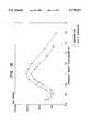
- thermal NO xcan be controlled by regulation of the peak flame temperature, and as shown in FIG. 1 using kinetic calculations, if the temperature can be lowered enough the NO x emissions from a "true" premixed natural gas flame operating at 15% excess air can be reduced to extremely low values (less than 1 ppmv).
- FIG. 1shows the relationship between thermal NO x and temperature since for a premixed natural gas flame with an excess of oxygen, thermal NO x is the only route by which any significant NO x emissions are created.
- Low NO x gas burnershave been undergoing considerable development in recent years as governmental regulations have required burner manufacturers to comply with lower and lower NO x limits.
- Most of the existing low NO x gas burner designsare nozzle mix designs. In this approach the fuel is mixed with the air immediately downstream of the burner throat. These designs attempt to reduce NO x emissions by delaying the fuel and air mixing through some form of either air staging or fuel staging combined with flue gas recirculation ("FGR"). Delayed mixing can be effective in reducing both flame temperature and oxygen availability and consequently in providing a degree of thermal NO x control.
- delayed mixing burnersare not effective in reducing prompt NO x emissions and can actually exacerbate prompt NO x emissions. Delayed mixing burners can also lead to increased emissions of CO and total hydrocarbons. Stability problems often exist with delayed mixing burners which limit the amount of FGR which can be injected into the flame zone. Typical FGR levels at which current burners operate are at a ratio of around 20% recirculated flue gas relative to the total stack gas flow.
- premixed type burnerA further type of low NO x burner which has been developed in recent years is the premixed type burner.
- the fuel gas and oxidant gasesare mixed well upstream of the burner throat, e.g. at or prior to the windbox.
- These burnerscan be effective in reducing both thermal and prompt NO x emissions.
- problems with premixed type burnersinclude difficulty in applying high air preheat, concerns about flashback and explosions, and difficulties in applying the concept to duel fuel burners.
- Premix burnersalso typically have stability problems at high FGR rates.
- an outer shellwhich includes a windbox and a constricted tubular section in fluid communication therewith.
- a generally cylindrical bodyis mounted in the shell, coaxially with and spaced inwardly from the tubular section so that an annular flow channel or throat is defined between the body and the inner wall of the tubular section.
- Oxidant gasesare flowed under pressure from the windbox to the throat, and exit from a downstream outlet end.
- a divergent quarlis adjoined to the outlet end of the throat and define a combustion zone for the burner.
- a plurality of curved axial swirl vanesare mounted in the annular flow channel to impart swirl to the oxidant gases flowing downstream in the throat.
- Fuel gas injector meansare provided in the annular flow channel proximate or contiguous to the swirl vanes for injecting the fuel gas into the flow of oxidant gases at a point upstream of the outlet end.
- the fuel gas injection meanscomprise a plurality of spaced gas injectors, each being defined by a gas ejection hole and means to feed the gas thereto.
- the ratio of the number of gas ejection holes to the projected (i.e. transverse cross-sectional) area of the annular flow channel which is fed fuel gas by the injector meansis at least 200/ft 2 .
- One or more turbulence enhancing meansmay optionally be mounted in the throat at at least one of the upstream or downstream sides of the swirl vanes. These serve to induce fine scale turbulence into the flow to promote microscale mixing of the oxidant and fuel gases prior to combustion at the quarl.
- the gas injectorscan be located at the leading or trailing edges of the swirl vanes, and inject the fuel gas in the direction of the tangential component of the flow imparted by the swirl vanes.
- the gas injectorscan also be disposed on a plurality of hollow concentric rings which are mounted in the throat downstream of the swirl vanes.
- the injectorscan similarly comprise openings disposed in opposed concentric bands on the walls which define the inner and outer radii of the annular flow channel.
- the gas injectorscan also be located at the surfaces of the swirl vanes, with the vanes being hollow structures fed by a suitable manifold.
- the geometry of the burneris such that the product of the swirl number S and the quarl outlet to inlet diameter ratio C/B is in the range of 1.0 to 3.0.
- the gaseous fuelis injected at an axial coordinate which is spaced less than B in the upstream direction from the axial coordinate at which the quarl divergence begins; and sufficient mixing of the gaseous fuel with the air and recirculated flue gases is provided that these components are well-mixed down to a molecular scale at the axial coordinate of ignition. This procedure results in extremely low NO x , CO and hydrocarbon emissions from the burner.
- the swirl vaneswhich are mounted with their leading edges parallel to the axial flow of fuel and oxidant gases, and then slowly curve to the final desired angle, have a constant radius of curvature along the curved portion of the vane, whereby the curved portion is a section of a cylinder. This shape simplifies manufacturing using conventional metal fabricating techniques.
- FIGS. 3, 4, 5 and 6describe a representative embodiment of the apparatus disclosed in my prior applications.
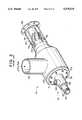
- FIG. 3an isometric perspective view thus appears of such prior art embodiment of burner apparatus 51.
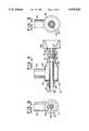
- FIGS. 4, 5 and 6,which are respectively longitudinal cross-sectional; and front and rear end views of apparatus 51.
- combustion air(which can be mixed with recirculated flue gas) is provided to the windbox 53 through a cylindrical conduit 55.
- Windbox 53adjoins a tubular section 57 which terminates at a flange 59, which is secured to a divergent quarl 58 (FIG. 12).
- the inner co-axial cylindrical body 61is comprised of a central hollow cylindrical tube 63 intended for receipt of an oil gun or a sight glass, and a surrounding tubular member or cylinder 65 which is spaced from the outside wall of tube 63 and closed at each end, by closures 67.
- a hollow annular space 68is thereby formed between tubular member 63 and cylinder 65, which serves as a manifold 68 for the fuel gas which is provided to such space via connector 69.
- the cylindrical body 61is positioned and spaced within wind box 53 and tubular section 61 by passing through flanges, one of which is seen at 71. The latter is secured to a plate 73 at the end of the wind box by bolts 75 and suitable fasteners (not shown). This arrangement enables easy disassembly, as for servicing and the like.
- a series of swirl vanes 77are provided in the annular space or throat 79 which is defined between tubular body 61 (specifically, between the outer wall of cylinder 65) and the inner wall of tubular member 57.)
- gas injector meansare provided which take the form of a plurality of tubes 81, each of which is provided with multiple holes 83. It will be evident that the tubes 81, being hollow members, are in communication at their open one end with the interior of the gas manifold 68 defined within member 65, which therefore serves as a feed source for the fuel gas.
- the fuel gasis discharged in the direction of the openings 83, so that in each instance fuel is injected into the throat directly at the leading edges of the swirl vanes and in the direction of the tangential component of the flow imparted by the swirl vanes 77. Accordingly, the gas injection also acts to enhance the swirl number of the flow.
- basic rapid mix burner(hereinafter at times referred to as the "basic rapid mix burner” or “basic RMB”) is extremely effective in achieving the desired results
- the basic RMB designresults in a burner size that is significantly larger than many existing burners.
- the large burner sizeis not inherently important to the rapid mix feature, the large burner size is important for creating an extremely stable flame which allows high flue gas recirculation rates to be used without concerns about the flame becoming unstable.
- One method of reducing the burner sizeis to increase the velocities through the burner.
- this methodhas the disadvantage of increasing the pressure drop through the burner.
- a higher pressure drop through the burnercreates other retrofit difficulties, including replacement of forced draft fans, increased operating costs associated with the higher fan pressure, structural limitations on the windbox and increased operating costs.
- a two stage rapid mix burner designprovides apparatus and method which both significantly reduces the burner size of a rapid mix burner, and/or the burner pressure drop, while maintaining the rapid mix feature and stability of the basic rapid mix design.
- the two stage rapid mix burner design of the inventioncan also be easily altered to fit in non-circular geometries, such as a corner or tangential fired boiler.
- the present inventionuses a circular basic rapid mix burner (i.e. as in my earlier applications), located internally inside a larger burner which can be non-circular.
- the inner burnerprovides the flow of hot gases which stabilizes the outer burner.
- the combustion gases produced in the inner burnerreplace the strong internal recirculation flow generated by the basic RMB as an ignition source for the outer burner flow.
- the inner burneruses the same type swirler, burner and quarl geometry as the basic RMB burner described in my previous applications and consequently has the desired stability and NO x , CO and HC performance.
- the outer portion of the burneruses a rapid mix injection grid and consequently also has the desired NO x , CO and HC performance. Since the flame stability is provided by the inner burner, swirl vanes or a divergent quarl for the outer portion of the burner are not required.
- the inner burneris circular with a cylindrical tube mounted in the center defining an annular space between the outer and inner tubes.
- a plurality of curved fixed axial vanesare mounted in the annular space to impart swirl to the oxidant gases flowing through the burner.
- the number of vanesvaries linearly with the burner diameter.
- the typical spacing between vanes, on the inner annulusis approximately one inch.
- Fuel injection meansare provided in the annular flow channel proximate or contiguous to the swirl vanes for injecting the fuel gas into the flow of oxidant gases.
- the fuel gas injection meanscomprises a plurality of spaced gas injectors, each defined by a gas injection hole and a means to feed the gas thereto.
- the ratio of the number of gas injection holes to the projected area of the annular flow channel which is fed fuel gas by the injector meansis at least 200/ft 2 .
- a divergent quarlis adjoined to the outlet end of the inner burner and defines a combustion zone for the burner. The purpose of the quarl is to both promote strong internal recirculation within the inner burner and to provide enough residence time to allow the stability of the flame from the inner burner to be relatively unaffected by the outer portion of the burner. Consequently, a quarl length/inlet diameter ratio of at least 1.75 is desired.
- the gas injectors for the inner burnercan be located at the leading or trailing edges of the swirl vanes, and inject the fuel in the direction of the tangential component and/or opposite to the direction of the tangential velocity component of the flow imparted by the swirl vanes.
- the gas injectorscan also be disposed on a plurality of hollow concentric rings which are mounted in the throat downstream of the swirl vanes.
- the injected gascan similarly comprise openings disposed in opposed concentric bands on the walls which define the inner and outer radii of the annular flow channel.
- the gas injectorscan also be located at the surfaces of the swirl vanes, with the vanes being hollow structures fed by a suitable manifold. Details of these arrangements are shown in my Ser. Nos. 092,979 and 188,586 applications.
- the inner burneris enclosed by a second annular space or number of outer burners cells for which the inner burner acts as an ignition source.
- the air to the outer burner annulus or regionscan be fed from either a separate windbox or from a windbox common to both the inner and outer burner.
- the two most common geometries for the outer burnerare an annular space concentric to the inner burner or a rectangular region with the inner burner diameter less than or equal to the smaller dimension of the rectangular opening.
- the basic two stage RMB conceptcan function with outer burner geometries of any shape.
- rapid mix gas injectorsare positioned to provide rapid mixing between the oxidant and fuel.
- the gas injectorscan take the shape of radial spuds fed from either a outer or inner manifold.
- the spudsare drilled with holes to provide the desired mixing rate between fuel and oxidant.
- the gas injection spudscan also take the shape of concentric rings, horizontal or vertical grids or other shapes compatible with the outer burner geometry.
- the spacing between gas injection spudsis approximately one inch with the spacing between the holes drilled into the spuds being in the range 0.2 to 0.4 inches.
- the spacing of the fuel gas injection holesprovides uniform gas distribution within the oxidant.
- each gas spudis at least 3 times the total area of the injection holes in each spud, to provide adequate gas distribution to each hole.
- 1/4 inch diameter cylindrical tubingis preferably not used for the injection spuds. Instead either "racetrack" oval tubing, airfoil tubing or fabricated injectors having a maximum width, in a plane defined by the cross-sectional area of the burner throat, of 1/4 inch and a length, normal to the same plane, determined by the required cross-sectional area and wall thickness of the tube.
- the "flattened" faces of these tubesare thus the surfaces at which the ejector holes are present, and thus the direction of gas ejection is generally tangential to a radius drawn to the hole, and in a plane or planes transverse to the axis of the burner.
- an injection spudmay have a height of 3 inches with an average hole spacing of 0.25 inch (resulting in 12 holes). Using 1/16 inch holes, the total injection area would be 0.0368 square inches per spud. If tubing with a 0.035 inch wall is used, and the tube minor axis is 0.25 inch, a length for the major axis of the tube of at least 0.625 inches would be required to maintain a inlet area for the spud of at least 3 times the injection area.
- the ratio of the number of gas injection holes to the projected cross-sectional area of the annular flow channelis at least 200/ft 2 .
- the diameter of the holesis determined by the same criteria as discussed in my prior pending applications.
- Meansmay be provided to enhance the mixing of the gas and oxidant in the outer portion of the burner. These means may include the use of screens or perforated plates which induce fine scale turbulence into the flow, or axial swirl vanes may be used in the outer flow to both induce mixing and to control the flame shape.
- the heat input ratio between the inner and outer burnersis typically in the range of 5% to 20% when the burner is operated at maximum capacity.
- the heat input to the inner portion of the burnerwould remain fixed and, if a lower heat input is required, the fuel and oxidant rate would be decreased in the outer burner only.
- the burnercould be operated with fuel input to the inner portion of the burner only, in which case the burner would operate as a standard RMB.
- the thermal inputs of the inner and outer burnercould be controlled together. In this mode the inner and outer burner would be controlled so that the heat input from both burner portions would vary linearly; i.e. if the total input is 50% both the inner and outer burners would operate at 50% of maximum input.
- recirculated flue gasis added to the combustion air of both the inner and outer burner.
- the FGRis added far enough upstream of the burner to result in premixed air and FGR at the gas injection point.
- air or another inertcan be used to reduce the flame temperature. The amount of FGR used is dependent on the desired NO x level.
- an oil guncan be inserted through the center, along the axis of the inner burner, to provide backup oil burning capability.
- the swirl vanes and quarl of the inner burnerwill provide the necessary flame stability. All the oil will be injected through the center of the burner, providing the delayed fuel and air mixing (internal staging) necessary for NO x control with oils which contain a significant amount of fuel nitrogen.
- FIG. 1is a graphical depiction showing calculated NO x versus adiabatic flame temperature for a premixed flame with 15% excess air;
- FIG. 2is a further graph showing kinetic calculation of prompt NO x (HCN and NH 3 );
- FIG. 3a perspective view appears of an embodiment of prior art burner apparatus in accordance with the disclosure of my Ser. Nos. 092,979 and 188,586 applications;
- FIG. 4is a longitudinal cross-sectional view through the apparatus of FIG. 3;
- FIGS. 5 and 6are respectively front and rear-end views of the apparatus of FIGS. 3 and 4.
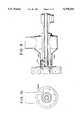
- FIG. 7is a longitudinal cross-sectional view, through a first embodiment of apparatus in accordance with the present invention.
- FIG. 8is a front end view of the FIG. 7 apparatus
- FIG. 9is a longitudinal cross-sectional view, through a second embodiment of apparatus in accordance with the present invention.
- FIG. 10is a front end view of the FIG. 9 apparatus
- FIG. 11is a schematic longitudinal cross-sectional view of a two stage apparatus in accordance with the invention, which is provided with a rectangular outer burner portion;
- FIG. 12is an end view of the FIG. 11 apparatus
- FIG. 13is a schematic end view of 6 burners as they would appear in one corner of a typical corner fired burner application
- FIG. 14is a graphical depiction showing the effect of varying the ratio of the inner/total burner heat input as a function of FGR rate with ambient air, and also compares the performance of the rectangular two stage RMB with the basic RMB;
- FIG. 15is a graph showing the CO and total hydrocarbon emissions (THC) as a function of the FGR rate for the two stage burner of the invention.
- FIG. 16is a graph comparing the effect of the inner/total burner heat input as a function of FGR rate for 500° F. air preheat;
- FIG. 17is a graph illustrating an example of NO x , CO, and THC performance of the invention as a function of excess air levels
- FIG. 18is a graph showing the performance of a burner in accordance with the invention, calculated from chemical kinetics, as a function of the burner stoichiometry.
- FIG. 19is a graph comparing measured results operating a two stage burner in accordance with the invention in a biased firing mode with the fuel lean burner operating at 94% excess air and the fuel rich burner at 0.63 stoichiometry, maintaining an overall excess air level of 10%, with the same burners operating at the 10% excess air.
- FIGS. 7 and 8respectively depict a longitudinal cross-sectional and front end view of a two stage circular RMB 100 in accordance with the present invention.
- This arrangementemploys separate windboxes 102 and 104 for the inner and outer portions of the burner.
- Air and FGRrecirculated flue gas
- ducts 106 and 108are provided under positive pressure by conventional fan means (not shown) via ducts 106 and 108 to both windboxes.
- the air and flue gas mixtureproceed through the inner burner throat 110 to the swirl vanes 112.
- the design of the swirl vanes and gas injectorscorrespond to the disclosure of my prior applications.
- gasis injected in the same direction as the curvature of the swirl vanes, this arrangement being similar to that shown in FIGS. 3 through 6.
- the air, gas, flue gas mixturethen passes through the swirl vanes resulting in a well mixed composition at the beginning of the quarl divergence 114. Ignition of the mixture occurs early in the quarl 116 and, at the axial position corresponding to the quarl exit, a significant amount of the fuel is combusted.
- the ignited gasesproceed to a combustion chamber which in use is adjoined to the burner at the quarl exit.
- the geometrical design of the inner burneris consistent with the design of the basic RMB--see e.g. FIGS. 3 to 6.
- the dimensions of the annular region defined by the ratio of the inner diameter of the swirl vanes divided by the outer diameter of the swirl vanes,is preferably in the range of 0.6 to 0.8.
- the product of the swirl number with the quarl outlet to inlet ratiois preferably in the range 1.0 to 3.0.
- the quarl exit angle 118would typically be zero degrees. However quarl exit angles ranging from either greater (diverging at the exit) or less than zero degrees (converging at the exit) may be desirable for some applications. To provide adequate residence time within the quarl for the inner burner, the quarl length/quarl inlet diameter ratio should be a minimum of 1.75.
- the air and flue gas mixture comprising the oxidantis also fed into the windbox 104 that supplies the outer burner.
- This oxidant streamis fed into the annular flow region or channel 120 between the outer burner wall 122 and the tube 124 extending back and partially defining the outer wall of the inner burner.
- the oxidantpasses through two rows 126, 128 of gas injectors which extend radially into the outer burner annular flow channel 120.
- the gas injectorsare fed fuel gas from manifold 131 into which the injectors extend and with which they communicate. Fuel gas to manifold 131 is provided via port 133.
- Wall 122is secured to an outer refractory piece 135 by flange 139.
- Piece 135essentially functions as a quarl for the outer burner. It has a central opening 137 forming part of flow channel 120.
- Gasis fed through a number of injectors in rows 126, 128 which extend along radii.
- Each radial spud 132has a series of injection holes which inject the gas normal to the oxidant flow in the same direction as the tangential component provided to the oxidant using the swirl vanes of the inner burner.
- fuel injection opposite to the swirl direction of the inner burner or in both directions simultaneouslyare also effective means of producing the desired mixing results.
- the totality of gas injection holes in effectdefine a grid of injection points, spaced by about 0.25 inches in the radial direction and 0.5 inch in the circumferential direction.
- the objectiveis to provide premixed air/FGR/fuel before the outer burner gases are ignited by the combustion gases from the inner burner.
- the diameter of the holesare based on the rapid mix design disclosed in my prior said applications.
- the outer burner gas spudsshown in FIG. 7, are aligned in two rows in order to generate additional mixing energy in the wake of each row.
- the apparatus 100there are two rows of spuds, each consisting of 20 cylindrical tubes.
- the tubes in one roware offset 15° from the tubes in the other row.
- the spudsmay be aligned in either a single row or multiple rows.
- the spudsmay take the shape of cylindrical tubes, oval tubes or other fabricated shapes having an minor outside diameter of approximately 0.25 inch.
- the cross-sectional area of each gas spudis typically at least 3 times the total area of the total injection holes in each spud, to provide uniform gas distribution to each hole.
- swirl vanes 134can be added to the outer annular or flow channel 120.
- the purpose of the swirl vanes 134is to accelerate the mixing between the fuel and oxidant.
- the swirl vaneswill also provide a degree of control over the flame shape with a higher swirl level resulting in a shorter, wider flame.
- swirl vanes with an exit angle of 30 degreesare used, but vanes with exit angles in the range 10 to 50 degrees may be used to control the flame shape.
- the radial spuds 160 in the embodiment of FIGS. 9 and 10are oval or flattened tubes, unlike the cylindrical tubes of FIGS. 7 and 8. Within one outer tube diameter downstream of the gas injectors the outer burner flow will enter a refractory section.
- the refractorywill extend downstream, typically ending at the same axial position or extending slightly downstream, of the inner quarl.
- the refractory sectioncould, however, be replaced with a cylinder formed from the surrounding water wall tubes, if sufficient space is not available in the water wall.
- FIGS. 11 and 12show a two stage RMB having a rectangular outer burner portion. This geometry corresponds to corner (or tangentially fired boilers) which make up a significant fraction of the large industrial and utility boiler market.
- FIG. 13also shows a view of 6 burners as they would appear in one corner of a typical corner fired boiler application.
- the inner burneris conceptually the same as the annular two stage burner described for FIGS. 7 through 10.
- the quarl of the inner burnerhas the same outside diameter as the smaller dimension of the rectangular boundary comprising the outer burner.
- the gas injection manifold in the outer burnerconsists of a series of parallel vertical spuds 1/4 inch in width and spaced by one inch center to center. Parallel horizontal spuds would be equally effective in generating the desired rapid mixing.
- the cross-sectional area of each vertical injection spudis large enough to provide uniform gas distribution to each hole in the injector. Typically the cross-sectional area to each spud is at least 3 times the total area of the injection holes.
- Each spudhas a series of holes spaced in 1/4 inch increments along its length.
- the gas injection spuds in the upper and lower burner cellsare fed from separate manifolds located near to the upper and lower surface of the outer burner. The gas injection holes may be on either one side of the vertical manifold or on both sides depending on the application.
- a screen, perforated plate or other mixing enhancermay be placed downstream of the gas injectors in the outer burner cells, to enhance mixing between the fuel and oxidant.
- the objective of the gas distribution system and any screens or perforated plates, located downstream of the gas injection point,is to generate premixed fuel and oxidant upstream of the ignition point.
- FIG. 14shows the results of the tests varying the ratio of the inner/total burner heat input as a function of FGR rate with ambient air. Burner stability and NO x , at a constant FGR rate, are relatively unaffected by the ratio of the inner to total burner heat input.
- FIG. 14also compares the performance of the rectangular two stage RMB burner with the standard RMB. For FGR rates higher than about 20%, the two stage burner has lower NO x emissions for a given FGR rate than the standard burner. Both the two stage burner and standard RMB are capable of NO x emissions well below 10 ppm.
- FIG. 15shows the CO and total hydrocarbon emissions (THC) as a function of the FGR rate for the two stage burner. When NO x emissions as low as 5 ppm were achieved, both the CO and THC emissions were below the detection limit of 1 ppm.
- THCtotal hydrocarbon emissions
- FIG. 16compares the effect of the inner/total burner heat input as a function of FGR rate for 500 F. air preheat. Again the NO x emissions and stability of the two stage burner were not a strong function of the ratio of the heat input ratio between the inner and total burner. For a given FGR rate above about 20%, the NO x emissions of the two stage burner were lower than for the standard RMB for a given FGR rate.
- FIGS. 17 through 19demonstrate that the two stage RMB has the capability of reducing NO x emissions well below 10 ppm with FGR rates less than or equal to those used for the standard RMB.
- the low NO x emissionscan be maintained with less than 1 ppm CO or THC emissions.
- the two stage burner designwill result in a maximum burner diameter of 33 inches compared to the standard RMB maximum diameter of 60 inches for the same burner capacity, FGR rate and pressure drop, with about the same flame stability, NO x , CO and THC emissions.
- the size reductionoccurs primarily for two reasons. First, since the outer burner does not require swirl vanes a higher axial velocity can be used for a given pressure drop. Second, since the flame in the outer burner is stabilized via the inner burner flame a quarl expansion for the outer burner is not required.
- the two stage burner RMBcan also be operated at high excess air levels to reduce NO x levels down to extremely low levels in the same manner as the standard RMB.
- FIG. 18shows the performance of the RMB, calculated from chemical kinetics, as a function of the burner stoichiometry. The data in FIG. 18 shows that even with air preheat, operating one burner near 80% excess air and another burner at a stoichiometry of 0.6 should result in NO x emissions from both burners less than 10 ppm.
- FIG. 19compares the measured results operating a two burner RMB installation in a biased firing mode, with the fuel lean burner operating at 94% excess air and the fuel rich burner operating at 0.63 stoichiometry, maintaining an overall excess air level of 10% with the same burners both operating at the 10% excess air.
- the data in the FIG. 9demonstrate that, without FGR, biased firing results in a reduction in NO x emissions from 300 ppm to 20 ppm. If FGR is used biased firing reduces the amount of FGR required to achieve 10 ppm NO x is reduced from 40% to less than 20%.
Landscapes
- Engineering & Computer Science (AREA)
- Chemical & Material Sciences (AREA)
- Combustion & Propulsion (AREA)
- Mechanical Engineering (AREA)
- General Engineering & Computer Science (AREA)
- Treating Waste Gases (AREA)
- Incineration Of Waste (AREA)
Abstract
Description
N+O.sub.2 =NO+O (1)
N+OH=NO+H (2)
N.sub.2 +O=NO+N (3)
Claims (22)
Priority Applications (7)
| Application Number | Priority Date | Filing Date | Title |
|---|---|---|---|
| US08/233,358US5470224A (en) | 1993-07-16 | 1994-04-26 | Apparatus and method for reducing NOx , CO and hydrocarbon emissions when burning gaseous fuels |
| TW083102347A01ATW330235B (en) | 1994-04-26 | 1994-05-12 | Apparatus and method for reducing Nox,CO and hydrocarbon emissions when burning gaseous fuels |
| AU23649/95AAU2364995A (en) | 1994-04-26 | 1995-04-26 | Apparatus and method for reducing nox, co and hydrocarbon emissions when burning gaseous fuels |
| PCT/US1995/005126WO1995029365A1 (en) | 1994-04-26 | 1995-04-26 | APPARATUS AND METHOD FOR REDUCING NOx, CO AND HYDROCARBON EMISSIONS WHEN BURNING GASEOUS FUELS |
| EP95917685AEP0753123A1 (en) | 1994-04-26 | 1995-04-26 | APPARATUS AND METHOD FOR REDUCING NO x?, CO AND HYDROCARBON EMISSIONS WHEN BURNING GASEOUS FUELS |
| CA002188778ACA2188778A1 (en) | 1994-04-26 | 1995-04-26 | Apparatus and method for reducing nox, co and hydrocarbon emissions when burning gaseous fuels |
| MXPA/A/1996/005152AMXPA96005152A (en) | 1994-04-26 | 1996-10-25 | Apparatus and method to reduce nox, co, and hydrocarbon emissions when gas combustibles are burned |
Applications Claiming Priority (3)
| Application Number | Priority Date | Filing Date | Title |
|---|---|---|---|
| US9297993A | 1993-07-16 | 1993-07-16 | |
| US08/188,586US5407347A (en) | 1993-07-16 | 1994-01-21 | Apparatus and method for reducing NOx, CO and hydrocarbon emissions when burning gaseous fuels |
| US08/233,358US5470224A (en) | 1993-07-16 | 1994-04-26 | Apparatus and method for reducing NOx , CO and hydrocarbon emissions when burning gaseous fuels |
Related Parent Applications (2)
| Application Number | Title | Priority Date | Filing Date |
|---|---|---|---|
| US9297993AContinuation-In-Part | 1993-07-16 | 1993-07-16 | |
| US08/188,586Continuation-In-PartUS5407347A (en) | 1993-07-16 | 1994-01-21 | Apparatus and method for reducing NOx, CO and hydrocarbon emissions when burning gaseous fuels |
Publications (1)
| Publication Number | Publication Date |
|---|---|
| US5470224Atrue US5470224A (en) | 1995-11-28 |
Family
ID=22876906
Family Applications (1)
| Application Number | Title | Priority Date | Filing Date |
|---|---|---|---|
| US08/233,358Expired - LifetimeUS5470224A (en) | 1993-07-16 | 1994-04-26 | Apparatus and method for reducing NOx , CO and hydrocarbon emissions when burning gaseous fuels |
Country Status (6)
| Country | Link |
|---|---|
| US (1) | US5470224A (en) |
| EP (1) | EP0753123A1 (en) |
| AU (1) | AU2364995A (en) |
| CA (1) | CA2188778A1 (en) |
| TW (1) | TW330235B (en) |
| WO (1) | WO1995029365A1 (en) |
Cited By (41)
| Publication number | Priority date | Publication date | Assignee | Title |
|---|---|---|---|---|
| US5681536A (en)* | 1996-05-07 | 1997-10-28 | Nebraska Public Power District | Injection lance for uniformly injecting anhydrous ammonia and air into a boiler cavity |
| US5829369A (en)* | 1996-11-12 | 1998-11-03 | The Babcock & Wilcox Company | Pulverized coal burner |
| US6123542A (en)* | 1998-11-03 | 2000-09-26 | American Air Liquide | Self-cooled oxygen-fuel burner for use in high-temperature and high-particulate furnaces |
| EP1009952A4 (en)* | 1997-05-13 | 2001-05-02 | Maxon Corp | Low-emissions industrial burner |
| US6383461B1 (en) | 1999-10-26 | 2002-05-07 | John Zink Company, Llc | Fuel dilution methods and apparatus for NOx reduction |
| US6524098B1 (en) | 2000-05-16 | 2003-02-25 | John Zink Company Llc | Burner assembly with swirler formed from concentric components |
| US20030175646A1 (en)* | 2002-03-16 | 2003-09-18 | George Stephens | Method for adjusting pre-mix burners to reduce NOx emissions |
| US20030175632A1 (en)* | 2002-03-16 | 2003-09-18 | George Stephens | Removable light-off port plug for use in burners |
| US20030175639A1 (en)* | 2002-03-16 | 2003-09-18 | Spicer David B. | Burner employing flue-gas recirculation system |
| US20030175634A1 (en)* | 2002-03-16 | 2003-09-18 | George Stephens | Burner with high flow area tip |
| US20030175635A1 (en)* | 2002-03-16 | 2003-09-18 | George Stephens | Burner employing flue-gas recirculation system with enlarged circulation duct |
| US20030175637A1 (en)* | 2002-03-16 | 2003-09-18 | George Stephens | Burner employing cooled flue gas recirculation |
| US6652265B2 (en) | 2000-12-06 | 2003-11-25 | North American Manufacturing Company | Burner apparatus and method |
| US20040018461A1 (en)* | 2002-03-16 | 2004-01-29 | George Stephens | Burner with low NOx emissions |
| WO2004048850A3 (en)* | 2002-11-22 | 2004-08-05 | Aalborg Ind As | A boiler, a method of controlling the combustion in a boiler and a heat exchanger tube for use in a boiler |
| US20040241601A1 (en)* | 2002-03-16 | 2004-12-02 | Spicer David B. | Burner tip for pre-mix burners |
| US6866502B2 (en) | 2002-03-16 | 2005-03-15 | Exxonmobil Chemical Patents Inc. | Burner system employing flue gas recirculation |
| US6881053B2 (en) | 2002-03-16 | 2005-04-19 | Exxonmobil Chemical Patents Inc. | Burner with high capacity venturi |
| US6884062B2 (en) | 2002-03-16 | 2005-04-26 | Exxonmobil Chemical Patents Inc. | Burner design for achieving higher rates of flue gas recirculation |
| US6887068B2 (en) | 2002-03-16 | 2005-05-03 | Exxonmobil Chemical Patents Inc. | Centering plate for burner |
| US6890172B2 (en) | 2002-03-16 | 2005-05-10 | Exxonmobil Chemical Patents Inc. | Burner with flue gas recirculation |
| US6893252B2 (en) | 2002-03-16 | 2005-05-17 | Exxonmobil Chemical Patents Inc. | Fuel spud for high temperature burners |
| US6893251B2 (en) | 2002-03-16 | 2005-05-17 | Exxon Mobil Chemical Patents Inc. | Burner design for reduced NOx emissions |
| US6986658B2 (en) | 2002-03-16 | 2006-01-17 | Exxonmobil Chemical Patents, Inc. | Burner employing steam injection |
| US20060281036A1 (en)* | 2005-06-08 | 2006-12-14 | Hamid Sarv | Tunneled multi-swirler for liquid fuel atomization |
| KR100657864B1 (en) | 2004-12-02 | 2006-12-15 | 한국기계연구원 | High Speed Injection Oxygen Combustor |
| US20070042307A1 (en)* | 2004-02-12 | 2007-02-22 | Alstom Technology Ltd | Premix burner arrangement for operating a combustion chamber and method for operating a combustion chamber |
| RU2306481C1 (en)* | 2006-04-13 | 2007-09-20 | Общество с ограниченной ответственностью "Агросервис" | Burner |
| US20070287108A1 (en)* | 2004-01-22 | 2007-12-13 | Linde Aktiengesellschaft | Apparatus and Method for a Burner |
| US20080276622A1 (en)* | 2007-05-07 | 2008-11-13 | Thomas Edward Johnson | Fuel nozzle and method of fabricating the same |
| US20100095905A1 (en)* | 2008-10-16 | 2010-04-22 | Lochinvar Corporation | Gas Fired Modulating Water Heating Appliance With Dual Combustion Air Premix Blowers |
| US20100116225A1 (en)* | 2008-10-16 | 2010-05-13 | Lochinvar Corporation | Integrated Dual Chamber Burner |
| CN102721060A (en)* | 2012-07-12 | 2012-10-10 | 穆瑞力 | Energy-efficient ceramic kiln burner |
| US20140373763A1 (en)* | 2013-06-25 | 2014-12-25 | Babcock & Wilcox Power Generation Group, Inc. | Burner with flame stabilizing/center air jet device for low quality fuel |
| US9097436B1 (en)* | 2010-12-27 | 2015-08-04 | Lochinvar, Llc | Integrated dual chamber burner with remote communicating flame strip |
| US9464805B2 (en) | 2013-01-16 | 2016-10-11 | Lochinvar, Llc | Modulating burner |
| CZ306941B6 (en)* | 2016-05-10 | 2017-09-27 | Pavel Skryja | An injector blowpipe with controlled flame characteristics and low concentrations of emitted nitrogen oxides and carbon monoxide |
| CN108443865A (en)* | 2018-02-27 | 2018-08-24 | 常州凯丽纺织有限公司 | A kind of three eddy flow ignition cylinders of three eddy flow fire-biomass gasification combustion engines |
| CN108679604A (en)* | 2018-06-08 | 2018-10-19 | 秦皇岛轻烃能源有限公司 | A kind of mixed sky/cigarette light-hydrocarbon gas prepares burner |
| CN109297018A (en)* | 2017-07-24 | 2019-02-01 | 福州华夏蓝天信息科技有限公司 | A kind of low nitrogen burner |
| US20250129936A1 (en)* | 2023-10-24 | 2025-04-24 | Modern Hydrogen, Inc. | Pyrolysis and combustion control in pyrolysis reactors, and associated systems and methods |
Families Citing this family (9)
| Publication number | Priority date | Publication date | Assignee | Title |
|---|---|---|---|---|
| US6695609B1 (en) | 2002-12-06 | 2004-02-24 | John Zink Company, Llc | Compact low NOx gas burner apparatus and methods |
| US7198482B2 (en) | 2004-02-10 | 2007-04-03 | John Zink Company, Llc | Compact low NOx gas burner apparatus and methods |
| US20070269755A2 (en)* | 2006-01-05 | 2007-11-22 | Petro-Chem Development Co., Inc. | Systems, apparatus and method for flameless combustion absent catalyst or high temperature oxidants |
| TWI421452B (en)* | 2008-11-14 | 2014-01-01 | Taiwan Sakura Corp | Clean and energy-saving cylindrical combustor |
| JP5357108B2 (en) | 2010-06-29 | 2013-12-04 | 大陽日酸株式会社 | Burner burning method |
| CN103234203A (en)* | 2013-04-26 | 2013-08-07 | 苏州斯马特环保科技有限公司 | Combustor for ignition furnace of sintering machine |
| CN105042635B (en)* | 2015-07-15 | 2018-02-16 | 长沙有色冶金设计研究院有限公司 | A kind of continuous pallettype sintering machine igniter |
| CN108728168A (en)* | 2017-04-14 | 2018-11-02 | 航天长征化学工程股份有限公司 | a gasification burner |
| CN110425537A (en)* | 2019-07-10 | 2019-11-08 | 无锡寸长南方工程技术有限公司 | Natural gas combustion nozzle structure and nitrogen oxides (NOx) discharge control method |
Citations (46)
| Publication number | Priority date | Publication date | Assignee | Title |
|---|---|---|---|---|
| US3115924A (en)* | 1960-02-03 | 1963-12-31 | Selas Corp Of America | Burner |
| US3227202A (en)* | 1964-03-10 | 1966-01-04 | Patterson Kelley Co | Gas burner |
| US3358736A (en)* | 1965-07-16 | 1967-12-19 | Zink Co John | Rotary gas burner assembly |
| US3749548A (en)* | 1971-06-28 | 1973-07-31 | Zink Co John | High intensity burner |
| US3775039A (en)* | 1971-01-22 | 1973-11-27 | Gen Chauffage Ind Pillard Frer | Burners for liquid or gaseous fuels |
| US3788065A (en)* | 1970-10-26 | 1974-01-29 | United Aircraft Corp | Annular combustion chamber for dissimilar fluids in swirling flow relationship |
| US3811277A (en)* | 1970-10-26 | 1974-05-21 | United Aircraft Corp | Annular combustion chamber for dissimilar fluids in swirling flow relationship |
| US3890084A (en)* | 1973-09-26 | 1975-06-17 | Coen Co | Method for reducing burner exhaust emissions |
| JPS5214228A (en)* | 1975-07-24 | 1977-02-03 | Osaka Gas Co Ltd | Conbustion system to restrain volume of emission of nitrogen oxide |
| US4083674A (en)* | 1975-03-14 | 1978-04-11 | Daimler-Benz Aktiengesellschaft | Film evaporation combustion chamber |
| US4094625A (en)* | 1975-02-28 | 1978-06-13 | Heurtey Efflutherm | Method and device for evaporation and thermal oxidation of liquid effluents |
| US4130389A (en)* | 1976-01-26 | 1978-12-19 | Sumitomo Metal Industries Limited | NOx depression type burners |
| US4155701A (en)* | 1977-09-26 | 1979-05-22 | The Trane Company | Variable capacity burner assembly |
| US4160640A (en)* | 1977-08-30 | 1979-07-10 | Maev Vladimir A | Method of fuel burning in combustion chambers and annular combustion chamber for carrying same into effect |
| US4221558A (en)* | 1978-02-21 | 1980-09-09 | Selas Corporation Of America | Burner for use with oil or gas |
| US4230445A (en)* | 1977-06-17 | 1980-10-28 | Sulzer Brothers Ltd. | Burner for a fluid fuel |
| US4297093A (en)* | 1978-09-06 | 1981-10-27 | Kobe Steel, Ltd. | Combustion method for reducing NOx and smoke emission |
| US4451230A (en)* | 1980-06-06 | 1984-05-29 | Italimpianti Societa Impianti P.A. | Radiant flat flame burner |
| US4479775A (en)* | 1981-12-04 | 1984-10-30 | Sivan Development And Implementation Of Technological Systems Ltd. | Vane structure burner for improved air-fuel combustion |
| US4496306A (en)* | 1978-06-09 | 1985-01-29 | Hitachi Shipbuilding & Engineering Co., Ltd. | Multi-stage combustion method for inhibiting formation of nitrogen oxides |
| US4505666A (en)* | 1981-09-28 | 1985-03-19 | John Zink Company | Staged fuel and air for low NOx burner |
| US4600377A (en)* | 1985-05-29 | 1986-07-15 | Cedarapids, Inc. | Refractoriless liquid fuel burner |
| US4701124A (en)* | 1985-03-04 | 1987-10-20 | Kraftwerk Union Aktiengesellschaft | Combustion chamber apparatus for combustion installations, especially for combustion chambers of gas turbine installations, and a method of operating the same |
| US4842509A (en)* | 1983-03-30 | 1989-06-27 | Shell Oil Company | Process for fuel combustion with low NOx soot and particulates emission |
| US4884555A (en)* | 1988-11-21 | 1989-12-05 | A. O. Smith Corporation | Swirl combuster burner |
| US4899670A (en)* | 1988-12-09 | 1990-02-13 | Air Products And Chemicals, Inc. | Means for providing oxygen enrichment for slurry and liquid fuel burners |
| US4943230A (en)* | 1988-10-11 | 1990-07-24 | Sundstrand Corporation | Fuel injector for achieving smokeless combustion reactions at high pressure ratios |
| EP0393484A1 (en)* | 1989-04-20 | 1990-10-24 | Asea Brown Boveri Ag | Combustion chamber arrangement |
| US5000679A (en)* | 1985-04-26 | 1991-03-19 | Nippon Kokan Kabushiki Kaisha | Burner with a cylindrical body |
| US5009174A (en)* | 1985-12-02 | 1991-04-23 | Exxon Research And Engineering Company | Acid gas burner |
| US5029557A (en)* | 1987-05-01 | 1991-07-09 | Donlee Technologies, Inc. | Cyclone combustion apparatus |
| US5062792A (en)* | 1987-01-26 | 1991-11-05 | Siemens Aktiengesellschaft | Hybrid burner for a pre-mixing operation with gas and/or oil, in particular for gas turbine systems |
| US5085577A (en)* | 1990-12-20 | 1992-02-04 | Meku Metallverarbeitunge Gmbh | Burner with toroidal-cyclone flow for boiler with liquid and gas fuel |
| US5092762A (en)* | 1991-01-15 | 1992-03-03 | Industrial Technology Research Institute | Radial vane swirl generator |
| US5135387A (en)* | 1989-10-19 | 1992-08-04 | It-Mcgill Environmental Systems, Inc. | Nitrogen oxide control using internally recirculated flue gas |
| GB2252400A (en)* | 1991-01-29 | 1992-08-05 | Ind Tech Res Inst | Air swirl generator |
| US5147199A (en)* | 1986-12-12 | 1992-09-15 | Edmond Perthuis | Double fuel jet burner and method for its implementation |
| US5161946A (en)* | 1990-12-03 | 1992-11-10 | Industrial Technology Research Institute | Swirl generator with axial vanes |
| WO1992019913A1 (en)* | 1991-04-25 | 1992-11-12 | Siemens Aktiengesellschaft | Burner arrangement, especially for gas turbines, for the low-pollutant combustion of coal gas and other fuels |
| US5169304A (en)* | 1989-12-28 | 1992-12-08 | Institut Francais Du Petrole | Industrial liquid fuel burner with low nitrogen oxide emission, said burner generating several elementary flames and use thereof |
| US5186607A (en)* | 1990-12-03 | 1993-02-16 | Industrial Technology Research Institute | Swirl generator with axial vanes |
| US5192204A (en)* | 1992-03-20 | 1993-03-09 | Cedarapids, Inc. | Dual atomizing multifuel burner |
| DE4203598C1 (en)* | 1992-02-07 | 1993-06-24 | Industrial Technology Research Institute, Chutung, Hsing-Chu, Tw | Burner swirl-inducing component with axial vanes - has deflection points on curved vanes determined dependent on inner and outer radii edge curvature and passage diameter |
| US5240410A (en)* | 1991-12-30 | 1993-08-31 | Industrial Technology Research Institute | Dual fuel low nox burner |
| US5269678A (en)* | 1990-09-07 | 1993-12-14 | Koch Engineering Company, Inc. | Methods and apparatus for burning fuel with low NOx formation |
| US5269679A (en)* | 1992-10-16 | 1993-12-14 | Gas Research Institute | Staged air, recirculating flue gas low NOx burner |
Family Cites Families (6)
| Publication number | Priority date | Publication date | Assignee | Title |
|---|---|---|---|---|
| JPS5228251B2 (en)* | 1974-03-05 | 1977-07-26 | ||
| JPS597885B2 (en)* | 1978-12-15 | 1984-02-21 | 株式会社日立製作所 | gas burner nozzle |
| JPS5691108A (en)* | 1979-12-21 | 1981-07-23 | Babcock Hitachi Kk | Combustion method capable of reducing nox and uncombusted substance |
| DE3241162A1 (en)* | 1982-11-08 | 1984-05-10 | Kraftwerk Union AG, 4330 Mülheim | PRE-MIXING BURNER WITH INTEGRATED DIFFUSION BURNER |
| US5022849A (en)* | 1988-07-18 | 1991-06-11 | Hitachi, Ltd. | Low NOx burning method and low NOx burner apparatus |
| CN1017744B (en)* | 1988-12-26 | 1992-08-05 | 株式会社日立制作所 | Low nitrogen oxide boiler |
- 1994
- 1994-04-26USUS08/233,358patent/US5470224A/ennot_activeExpired - Lifetime
- 1994-05-12TWTW083102347A01Apatent/TW330235B/enactive
- 1995
- 1995-04-26EPEP95917685Apatent/EP0753123A1/ennot_activeWithdrawn
- 1995-04-26CACA002188778Apatent/CA2188778A1/ennot_activeAbandoned
- 1995-04-26AUAU23649/95Apatent/AU2364995A/ennot_activeAbandoned
- 1995-04-26WOPCT/US1995/005126patent/WO1995029365A1/ennot_activeApplication Discontinuation
Patent Citations (48)
| Publication number | Priority date | Publication date | Assignee | Title |
|---|---|---|---|---|
| US3115924A (en)* | 1960-02-03 | 1963-12-31 | Selas Corp Of America | Burner |
| US3227202A (en)* | 1964-03-10 | 1966-01-04 | Patterson Kelley Co | Gas burner |
| US3358736A (en)* | 1965-07-16 | 1967-12-19 | Zink Co John | Rotary gas burner assembly |
| US3788065A (en)* | 1970-10-26 | 1974-01-29 | United Aircraft Corp | Annular combustion chamber for dissimilar fluids in swirling flow relationship |
| US3811277A (en)* | 1970-10-26 | 1974-05-21 | United Aircraft Corp | Annular combustion chamber for dissimilar fluids in swirling flow relationship |
| US3775039A (en)* | 1971-01-22 | 1973-11-27 | Gen Chauffage Ind Pillard Frer | Burners for liquid or gaseous fuels |
| US3749548A (en)* | 1971-06-28 | 1973-07-31 | Zink Co John | High intensity burner |
| US3890084A (en)* | 1973-09-26 | 1975-06-17 | Coen Co | Method for reducing burner exhaust emissions |
| US4094625A (en)* | 1975-02-28 | 1978-06-13 | Heurtey Efflutherm | Method and device for evaporation and thermal oxidation of liquid effluents |
| US4083674A (en)* | 1975-03-14 | 1978-04-11 | Daimler-Benz Aktiengesellschaft | Film evaporation combustion chamber |
| JPS5214228A (en)* | 1975-07-24 | 1977-02-03 | Osaka Gas Co Ltd | Conbustion system to restrain volume of emission of nitrogen oxide |
| US4130389A (en)* | 1976-01-26 | 1978-12-19 | Sumitomo Metal Industries Limited | NOx depression type burners |
| US4230445A (en)* | 1977-06-17 | 1980-10-28 | Sulzer Brothers Ltd. | Burner for a fluid fuel |
| US4160640A (en)* | 1977-08-30 | 1979-07-10 | Maev Vladimir A | Method of fuel burning in combustion chambers and annular combustion chamber for carrying same into effect |
| US4155701A (en)* | 1977-09-26 | 1979-05-22 | The Trane Company | Variable capacity burner assembly |
| US4221558A (en)* | 1978-02-21 | 1980-09-09 | Selas Corporation Of America | Burner for use with oil or gas |
| US4496306A (en)* | 1978-06-09 | 1985-01-29 | Hitachi Shipbuilding & Engineering Co., Ltd. | Multi-stage combustion method for inhibiting formation of nitrogen oxides |
| US4297093A (en)* | 1978-09-06 | 1981-10-27 | Kobe Steel, Ltd. | Combustion method for reducing NOx and smoke emission |
| US4451230A (en)* | 1980-06-06 | 1984-05-29 | Italimpianti Societa Impianti P.A. | Radiant flat flame burner |
| US4505666A (en)* | 1981-09-28 | 1985-03-19 | John Zink Company | Staged fuel and air for low NOx burner |
| US4479775A (en)* | 1981-12-04 | 1984-10-30 | Sivan Development And Implementation Of Technological Systems Ltd. | Vane structure burner for improved air-fuel combustion |
| US4842509A (en)* | 1983-03-30 | 1989-06-27 | Shell Oil Company | Process for fuel combustion with low NOx soot and particulates emission |
| EP0193838B1 (en)* | 1985-03-04 | 1989-05-03 | Siemens Aktiengesellschaft | Burner disposition for combustion installations, especially for combustion chambers of gas turbine installations, and method for its operation |
| US4701124A (en)* | 1985-03-04 | 1987-10-20 | Kraftwerk Union Aktiengesellschaft | Combustion chamber apparatus for combustion installations, especially for combustion chambers of gas turbine installations, and a method of operating the same |
| US5000679A (en)* | 1985-04-26 | 1991-03-19 | Nippon Kokan Kabushiki Kaisha | Burner with a cylindrical body |
| US4600377A (en)* | 1985-05-29 | 1986-07-15 | Cedarapids, Inc. | Refractoriless liquid fuel burner |
| US5009174A (en)* | 1985-12-02 | 1991-04-23 | Exxon Research And Engineering Company | Acid gas burner |
| US5147199A (en)* | 1986-12-12 | 1992-09-15 | Edmond Perthuis | Double fuel jet burner and method for its implementation |
| US5062792A (en)* | 1987-01-26 | 1991-11-05 | Siemens Aktiengesellschaft | Hybrid burner for a pre-mixing operation with gas and/or oil, in particular for gas turbine systems |
| US5029557A (en)* | 1987-05-01 | 1991-07-09 | Donlee Technologies, Inc. | Cyclone combustion apparatus |
| US4943230A (en)* | 1988-10-11 | 1990-07-24 | Sundstrand Corporation | Fuel injector for achieving smokeless combustion reactions at high pressure ratios |
| US4884555A (en)* | 1988-11-21 | 1989-12-05 | A. O. Smith Corporation | Swirl combuster burner |
| US4899670A (en)* | 1988-12-09 | 1990-02-13 | Air Products And Chemicals, Inc. | Means for providing oxygen enrichment for slurry and liquid fuel burners |
| EP0393484A1 (en)* | 1989-04-20 | 1990-10-24 | Asea Brown Boveri Ag | Combustion chamber arrangement |
| US5101633A (en)* | 1989-04-20 | 1992-04-07 | Asea Brown Boveri Limited | Burner arrangement including coaxial swirler with extended vane portions |
| US5135387A (en)* | 1989-10-19 | 1992-08-04 | It-Mcgill Environmental Systems, Inc. | Nitrogen oxide control using internally recirculated flue gas |
| US5169304A (en)* | 1989-12-28 | 1992-12-08 | Institut Francais Du Petrole | Industrial liquid fuel burner with low nitrogen oxide emission, said burner generating several elementary flames and use thereof |
| US5269678A (en)* | 1990-09-07 | 1993-12-14 | Koch Engineering Company, Inc. | Methods and apparatus for burning fuel with low NOx formation |
| US5161946A (en)* | 1990-12-03 | 1992-11-10 | Industrial Technology Research Institute | Swirl generator with axial vanes |
| US5186607A (en)* | 1990-12-03 | 1993-02-16 | Industrial Technology Research Institute | Swirl generator with axial vanes |
| US5085577A (en)* | 1990-12-20 | 1992-02-04 | Meku Metallverarbeitunge Gmbh | Burner with toroidal-cyclone flow for boiler with liquid and gas fuel |
| US5092762A (en)* | 1991-01-15 | 1992-03-03 | Industrial Technology Research Institute | Radial vane swirl generator |
| GB2252400A (en)* | 1991-01-29 | 1992-08-05 | Ind Tech Res Inst | Air swirl generator |
| WO1992019913A1 (en)* | 1991-04-25 | 1992-11-12 | Siemens Aktiengesellschaft | Burner arrangement, especially for gas turbines, for the low-pollutant combustion of coal gas and other fuels |
| US5240410A (en)* | 1991-12-30 | 1993-08-31 | Industrial Technology Research Institute | Dual fuel low nox burner |
| DE4203598C1 (en)* | 1992-02-07 | 1993-06-24 | Industrial Technology Research Institute, Chutung, Hsing-Chu, Tw | Burner swirl-inducing component with axial vanes - has deflection points on curved vanes determined dependent on inner and outer radii edge curvature and passage diameter |
| US5192204A (en)* | 1992-03-20 | 1993-03-09 | Cedarapids, Inc. | Dual atomizing multifuel burner |
| US5269679A (en)* | 1992-10-16 | 1993-12-14 | Gas Research Institute | Staged air, recirculating flue gas low NOx burner |
Cited By (59)
| Publication number | Priority date | Publication date | Assignee | Title |
|---|---|---|---|---|
| US5681536A (en)* | 1996-05-07 | 1997-10-28 | Nebraska Public Power District | Injection lance for uniformly injecting anhydrous ammonia and air into a boiler cavity |
| US5829369A (en)* | 1996-11-12 | 1998-11-03 | The Babcock & Wilcox Company | Pulverized coal burner |
| EP1009952A4 (en)* | 1997-05-13 | 2001-05-02 | Maxon Corp | Low-emissions industrial burner |
| US6123542A (en)* | 1998-11-03 | 2000-09-26 | American Air Liquide | Self-cooled oxygen-fuel burner for use in high-temperature and high-particulate furnaces |
| US6210151B1 (en)* | 1998-11-03 | 2001-04-03 | American Air Liquide | Self-cooled oxygen-fuel burner for use in high-temperature and high-particulate furnaces |
| US6383461B1 (en) | 1999-10-26 | 2002-05-07 | John Zink Company, Llc | Fuel dilution methods and apparatus for NOx reduction |
| US6524098B1 (en) | 2000-05-16 | 2003-02-25 | John Zink Company Llc | Burner assembly with swirler formed from concentric components |
| US6652265B2 (en) | 2000-12-06 | 2003-11-25 | North American Manufacturing Company | Burner apparatus and method |
| US20050147934A1 (en)* | 2002-03-16 | 2005-07-07 | George Stephens | Burner with high capacity venturi |
| US6884062B2 (en) | 2002-03-16 | 2005-04-26 | Exxonmobil Chemical Patents Inc. | Burner design for achieving higher rates of flue gas recirculation |
| US20030175639A1 (en)* | 2002-03-16 | 2003-09-18 | Spicer David B. | Burner employing flue-gas recirculation system |
| US20030175634A1 (en)* | 2002-03-16 | 2003-09-18 | George Stephens | Burner with high flow area tip |
| US20030175635A1 (en)* | 2002-03-16 | 2003-09-18 | George Stephens | Burner employing flue-gas recirculation system with enlarged circulation duct |
| US20030175637A1 (en)* | 2002-03-16 | 2003-09-18 | George Stephens | Burner employing cooled flue gas recirculation |
| US20040018461A1 (en)* | 2002-03-16 | 2004-01-29 | George Stephens | Burner with low NOx emissions |
| US20040241601A1 (en)* | 2002-03-16 | 2004-12-02 | Spicer David B. | Burner tip for pre-mix burners |
| US6846175B2 (en) | 2002-03-16 | 2005-01-25 | Exxonmobil Chemical Patents Inc. | Burner employing flue-gas recirculation system |
| US6866502B2 (en) | 2002-03-16 | 2005-03-15 | Exxonmobil Chemical Patents Inc. | Burner system employing flue gas recirculation |
| US6869277B2 (en) | 2002-03-16 | 2005-03-22 | Exxonmobil Chemical Patents Inc. | Burner employing cooled flue gas recirculation |
| US6877980B2 (en) | 2002-03-16 | 2005-04-12 | Exxonmobil Chemical Patents Inc. | Burner with low NOx emissions |
| US6881053B2 (en) | 2002-03-16 | 2005-04-19 | Exxonmobil Chemical Patents Inc. | Burner with high capacity venturi |
| US7322818B2 (en) | 2002-03-16 | 2008-01-29 | Exxonmobil Chemical Patents Inc. | Method for adjusting pre-mix burners to reduce NOx emissions |
| US6887068B2 (en) | 2002-03-16 | 2005-05-03 | Exxonmobil Chemical Patents Inc. | Centering plate for burner |
| US6890171B2 (en) | 2002-03-16 | 2005-05-10 | Exxonmobil Chemical Patents, Inc. | Apparatus for optimizing burner performance |
| US6890172B2 (en) | 2002-03-16 | 2005-05-10 | Exxonmobil Chemical Patents Inc. | Burner with flue gas recirculation |
| US6893252B2 (en) | 2002-03-16 | 2005-05-17 | Exxonmobil Chemical Patents Inc. | Fuel spud for high temperature burners |
| US6893251B2 (en) | 2002-03-16 | 2005-05-17 | Exxon Mobil Chemical Patents Inc. | Burner design for reduced NOx emissions |
| US6902390B2 (en) | 2002-03-16 | 2005-06-07 | Exxonmobil Chemical Patents, Inc. | Burner tip for pre-mix burners |
| US20030175646A1 (en)* | 2002-03-16 | 2003-09-18 | George Stephens | Method for adjusting pre-mix burners to reduce NOx emissions |
| US6986658B2 (en) | 2002-03-16 | 2006-01-17 | Exxonmobil Chemical Patents, Inc. | Burner employing steam injection |
| US7025587B2 (en) | 2002-03-16 | 2006-04-11 | Exxonmobil Chemical Patents Inc. | Burner with high capacity venturi |
| US7476099B2 (en) | 2002-03-16 | 2009-01-13 | Exxonmobil Chemicals Patents Inc. | Removable light-off port plug for use in burners |
| US20030175632A1 (en)* | 2002-03-16 | 2003-09-18 | George Stephens | Removable light-off port plug for use in burners |
| WO2004048850A3 (en)* | 2002-11-22 | 2004-08-05 | Aalborg Ind As | A boiler, a method of controlling the combustion in a boiler and a heat exchanger tube for use in a boiler |
| US20070287108A1 (en)* | 2004-01-22 | 2007-12-13 | Linde Aktiengesellschaft | Apparatus and Method for a Burner |
| US20070042307A1 (en)* | 2004-02-12 | 2007-02-22 | Alstom Technology Ltd | Premix burner arrangement for operating a combustion chamber and method for operating a combustion chamber |
| KR100657864B1 (en) | 2004-12-02 | 2006-12-15 | 한국기계연구원 | High Speed Injection Oxygen Combustor |
| US7367798B2 (en)* | 2005-06-08 | 2008-05-06 | Hamid Sarv | Tunneled multi-swirler for liquid fuel atomization |
| US20060281036A1 (en)* | 2005-06-08 | 2006-12-14 | Hamid Sarv | Tunneled multi-swirler for liquid fuel atomization |
| RU2306481C1 (en)* | 2006-04-13 | 2007-09-20 | Общество с ограниченной ответственностью "Агросервис" | Burner |
| US20080276622A1 (en)* | 2007-05-07 | 2008-11-13 | Thomas Edward Johnson | Fuel nozzle and method of fabricating the same |
| US20100095905A1 (en)* | 2008-10-16 | 2010-04-22 | Lochinvar Corporation | Gas Fired Modulating Water Heating Appliance With Dual Combustion Air Premix Blowers |
| US20100116225A1 (en)* | 2008-10-16 | 2010-05-13 | Lochinvar Corporation | Integrated Dual Chamber Burner |
| US8286594B2 (en) | 2008-10-16 | 2012-10-16 | Lochinvar, Llc | Gas fired modulating water heating appliance with dual combustion air premix blowers |
| US8517720B2 (en) | 2008-10-16 | 2013-08-27 | Lochinvar, Llc | Integrated dual chamber burner |
| US8807092B2 (en) | 2008-10-16 | 2014-08-19 | Lochinvar, Llc | Gas fired modulating water heating appliance with dual combustion air premix blowers |
| US9097436B1 (en)* | 2010-12-27 | 2015-08-04 | Lochinvar, Llc | Integrated dual chamber burner with remote communicating flame strip |
| CN102721060B (en)* | 2012-07-12 | 2014-12-03 | 穆瑞力 | Energy-efficient ceramic kiln burner |
| CN102721060A (en)* | 2012-07-12 | 2012-10-10 | 穆瑞力 | Energy-efficient ceramic kiln burner |
| US9464805B2 (en) | 2013-01-16 | 2016-10-11 | Lochinvar, Llc | Modulating burner |
| US10208953B2 (en) | 2013-01-16 | 2019-02-19 | A. O. Smith Corporation | Modulating burner |
| US20140373763A1 (en)* | 2013-06-25 | 2014-12-25 | Babcock & Wilcox Power Generation Group, Inc. | Burner with flame stabilizing/center air jet device for low quality fuel |
| US9377191B2 (en)* | 2013-06-25 | 2016-06-28 | The Babcock & Wilcox Company | Burner with flame stabilizing/center air jet device for low quality fuel |
| CZ306941B6 (en)* | 2016-05-10 | 2017-09-27 | Pavel Skryja | An injector blowpipe with controlled flame characteristics and low concentrations of emitted nitrogen oxides and carbon monoxide |
| CN109297018A (en)* | 2017-07-24 | 2019-02-01 | 福州华夏蓝天信息科技有限公司 | A kind of low nitrogen burner |
| CN109297018B (en)* | 2017-07-24 | 2024-03-26 | 福州华夏蓝天信息科技有限公司 | Low nitrogen gas combustor |
| CN108443865A (en)* | 2018-02-27 | 2018-08-24 | 常州凯丽纺织有限公司 | A kind of three eddy flow ignition cylinders of three eddy flow fire-biomass gasification combustion engines |
| CN108679604A (en)* | 2018-06-08 | 2018-10-19 | 秦皇岛轻烃能源有限公司 | A kind of mixed sky/cigarette light-hydrocarbon gas prepares burner |
| US20250129936A1 (en)* | 2023-10-24 | 2025-04-24 | Modern Hydrogen, Inc. | Pyrolysis and combustion control in pyrolysis reactors, and associated systems and methods |
Also Published As
| Publication number | Publication date |
|---|---|
| EP0753123A1 (en) | 1997-01-15 |
| TW330235B (en) | 1998-04-21 |
| WO1995029365A1 (en) | 1995-11-02 |
| CA2188778A1 (en) | 1995-11-02 |
| MX9605152A (en) | 1997-09-30 |
| AU2364995A (en) | 1995-11-16 |
Similar Documents
| Publication | Publication Date | Title |
|---|---|---|
| US5470224A (en) | Apparatus and method for reducing NOx , CO and hydrocarbon emissions when burning gaseous fuels | |
| US5407347A (en) | Apparatus and method for reducing NOx, CO and hydrocarbon emissions when burning gaseous fuels | |
| EP0529779B1 (en) | Low NOx burners | |
| US6699030B2 (en) | Combustion in a multiburner furnace with selective flow of oxygen | |
| US6691515B2 (en) | Dry low combustion system with means for eliminating combustion noise | |
| KR100837713B1 (en) | ULTRA-LOW NOx BURNER ASSEMBLY | |
| EP0782681B1 (en) | Ultra low nox burner | |
| EP1736705A1 (en) | Combustion apparatus and combustion method | |
| US4135874A (en) | Two stage combustion furnace | |
| US6189464B1 (en) | Pulverized coal combustion burner and combustion method thereby | |
| AU2003212026A1 (en) | Nox-reduced combustion of concentrated coal streams | |
| US5220888A (en) | Cyclonic combustion | |
| EP1731833A1 (en) | Combustion apparatus | |
| US20140230701A1 (en) | Natural draft low swirl burner | |
| US20160238241A1 (en) | Lean gas burner | |
| US7914279B2 (en) | Method and apparatus for injecting a gas into a two-phase stream | |
| US5960724A (en) | Method for effecting control over a radially stratified flame core burner | |
| CA2167320C (en) | Apparatus and method for reducing nox, co and hydrocarbon emissions when burning gaseous fuels | |
| CN117606022A (en) | Ammonia burner, combustion system and combustion method | |
| TWI876026B (en) | Combustion system for a boiler with fuel stream distribution means in a burner and method of combustion | |
| US20060275724A1 (en) | Dynamic burner reconfiguration and combustion system for process heaters and boilers | |
| US20090029302A1 (en) | System of close coupled rapid mix burner cells | |
| WO2000061992A1 (en) | Tunneled multi-blade swirler/gas injector for a burner | |
| US20250060098A1 (en) | Dual-Fuel Burner and Method of Operation | |
| MXPA96005152A (en) | Apparatus and method to reduce nox, co, and hydrocarbon emissions when gas combustibles are burned |
Legal Events
| Date | Code | Title | Description |
|---|---|---|---|
| AS | Assignment | Owner name:RADIAN CORPORATION, TEXAS Free format text:ASSIGNMENT OF ASSIGNORS INTEREST;ASSIGNOR:BORTZ, STEVEN JAY;REEL/FRAME:007036/0561 Effective date:19940608 | |
| STCF | Information on status: patent grant | Free format text:PATENTED CASE | |
| AS | Assignment | Owner name:RADIAN INTERNATONAL, LLC., TEXAS Free format text:ASSIGNMENT OF ASSIGNORS INTEREST;ASSIGNOR:RADIAN CORPORATION;REEL/FRAME:008313/0479 Effective date:19960130 | |
| AS | Assignment | Owner name:CANADIAN IMPERIAL BANK OF COMMERCE, AS ADMINISTRAT Free format text:SECURITY INTEREST;ASSIGNORS:DAMES & MOORE GROUP (DE CORPORATION);AMAN ENVIRONMENTAL CONSTRUCTION, INC. (CA CORPORATION);BOVAY NORTHWEST, INC. (WA CORPORATION);AND OTHERS;REEL/FRAME:009633/0639 Effective date:19980731 | |
| FPAY | Fee payment | Year of fee payment:4 | |
| AS | Assignment | Owner name:DAMES & MOORE GROUP, CALIFORNIA Free format text:RELEASE OF SECURITY INTEREST;ASSIGNORS:CANADIAN IMPERIAL BANK OF COMMERCE, AS ADMINISTRATIVE AGENT;AMAN ENVIRONMENTAL CONSTRUCTION, INC. (CA CORPORATION);BOVAY NORTHWEST, INC. (WA CORPORATION);AND OTHERS;REEL/FRAME:010288/0838 Effective date:19990609 | |
| AS | Assignment | Owner name:WELLS FARGO BANK, NATIONAL ASSOCIATION, AS ADMINIS Free format text:SECURITY AGREEMENT;ASSIGNORS:DAMES & MOORE GROUP;AMAN ENVIRONMENTAL CONSTRUCTION, INC.;BRW GROUP, INC.;AND OTHERS;REEL/FRAME:010351/0345 Effective date:19990623 | |
| AS | Assignment | Owner name:WELLS FARGO BANK, NATIONAL ASSOCIATION, AS ADMINIS Free format text:SECURITY AGREEMENT;ASSIGNORS:DAMES & MOORE GROUP, A DELAWARE CORPORATION;AMAN ENVIRONMENTAL CONSTRUCTION, INC. (CA CORPORATION);BRW GROUP, INC. (DE CORPORATION);AND OTHERS;REEL/FRAME:011425/0439 Effective date:19990623 | |
| AS | Assignment | Owner name:O'BRIEN-KREITZBERG INC., CALIFORNIA Free format text:RERECORDING TO ADD "ASSIGNEE" NAMES INADVERTENTLY LISTED AS "ASSIGNORS"ON REEL 010288/FRAME 0838.;ASSIGNOR:CANADIAN IMPERIAL BANK OF COMMERCE, AS ADMINISTRATIVE AGENT;REEL/FRAME:012407/0445 Effective date:19990609 Owner name:DAMES & MOORE GROUP, CALIFORNIA Free format text:RERECORDING TO ADD "ASSIGNEE" NAMES INADVERTENTLY LISTED AS "ASSIGNORS"ON REEL 010288/FRAME 0838.;ASSIGNOR:CANADIAN IMPERIAL BANK OF COMMERCE, AS ADMINISTRATIVE AGENT;REEL/FRAME:012407/0445 Effective date:19990609 Owner name:AMAN ENVIRONMENTAL CONSTRUCTION, INC., CALIFORNIA Free format text:RERECORDING TO ADD "ASSIGNEE" NAMES INADVERTENTLY LISTED AS "ASSIGNORS"ON REEL 010288/FRAME 0838.;ASSIGNOR:CANADIAN IMPERIAL BANK OF COMMERCE, AS ADMINISTRATIVE AGENT;REEL/FRAME:012407/0445 Effective date:19990609 Owner name:BOVAY, NORTHWEST, INC., CALIFORNIA Free format text:RERECORDING TO ADD "ASSIGNEE" NAMES INADVERTENTLY LISTED AS "ASSIGNORS"ON REEL 010288/FRAME 0838.;ASSIGNOR:CANADIAN IMPERIAL BANK OF COMMERCE, AS ADMINISTRATIVE AGENT;REEL/FRAME:012407/0445 Effective date:19990609 Owner name:BRW GROUP, INC., CALIFORNIA Free format text:RERECORDING TO ADD "ASSIGNEE" NAMES INADVERTENTLY LISTED AS "ASSIGNORS"ON REEL 010288/FRAME 0838.;ASSIGNOR:CANADIAN IMPERIAL BANK OF COMMERCE, AS ADMINISTRATIVE AGENT;REEL/FRAME:012407/0445 Effective date:19990609 Owner name:BRW/HAZELET & ERDAL OF MICHIGAN, INC., CALIFORNIA Free format text:RERECORDING TO ADD "ASSIGNEE" NAMES INADVERTENTLY LISTED AS "ASSIGNORS"ON REEL 010288/FRAME 0838.;ASSIGNOR:CANADIAN IMPERIAL BANK OF COMMERCE, AS ADMINISTRATIVE AGENT;REEL/FRAME:012407/0445 Effective date:19990609 Owner name:BRW/HAZELET & ERDAL OF OHIO, INC., CALIFORNIA Free format text:RERECORDING TO ADD "ASSIGNEE" NAMES INADVERTENTLY LISTED AS "ASSIGNORS"ON REEL 010288/FRAME 0838.;ASSIGNOR:CANADIAN IMPERIAL BANK OF COMMERCE, AS ADMINISTRATIVE AGENT;REEL/FRAME:012407/0445 Effective date:19990609 Owner name:CLEVELAND WRECKING COMPANY, CALIFORNIA Free format text:RERECORDING TO ADD "ASSIGNEE" NAMES INADVERTENTLY LISTED AS "ASSIGNORS"ON REEL 010288/FRAME 0838.;ASSIGNOR:CANADIAN IMPERIAL BANK OF COMMERCE, AS ADMINISTRATIVE AGENT;REEL/FRAME:012407/0445 Effective date:19990609 Owner name:COLOR CAVE, INC., CALIFORNIA Free format text:RERECORDING TO ADD "ASSIGNEE" NAMES INADVERTENTLY LISTED AS "ASSIGNORS"ON REEL 010288/FRAME 0838.;ASSIGNOR:CANADIAN IMPERIAL BANK OF COMMERCE, AS ADMINISTRATIVE AGENT;REEL/FRAME:012407/0445 Effective date:19990609 Owner name:CONTRACTING RESOURCES INTERNATIONAL, INC., CALIFOR Free format text:RERECORDING TO ADD "ASSIGNEE" NAMES INADVERTENTLY LISTED AS "ASSIGNORS"ON REEL 010288/FRAME 0838.;ASSIGNOR:CANADIAN IMPERIAL BANK OF COMMERCE, AS ADMINISTRATIVE AGENT;REEL/FRAME:012407/0445 Effective date:19990609 Owner name:DM INVESTORS, INC., CALIFORNIA Free format text:RERECORDING TO ADD "ASSIGNEE" NAMES INADVERTENTLY LISTED AS "ASSIGNORS"ON REEL 010288/FRAME 0838.;ASSIGNOR:CANADIAN IMPERIAL BANK OF COMMERCE, AS ADMINISTRATIVE AGENT;REEL/FRAME:012407/0445 Effective date:19990609 Owner name:DAMES & MOORE AMERICA, L.P., CALIFORNIA Free format text:RERECORDING TO ADD "ASSIGNEE" NAMES INADVERTENTLY LISTED AS "ASSIGNORS"ON REEL 010288/FRAME 0838.;ASSIGNOR:CANADIAN IMPERIAL BANK OF COMMERCE, AS ADMINISTRATIVE AGENT;REEL/FRAME:012407/0445 Effective date:19990609 Owner name:DAMES & MOORE FOREIGN BRANCH OPERATIONS, INC., CAL Free format text:RERECORDING TO ADD "ASSIGNEE" NAMES INADVERTENTLY LISTED AS "ASSIGNORS"ON REEL 010288/FRAME 0838.;ASSIGNOR:CANADIAN IMPERIAL BANK OF COMMERCE, AS ADMINISTRATIVE AGENT;REEL/FRAME:012407/0445 Effective date:19990609 Owner name:DAMES & MOORE GROUP (NY), INC., CALIFORNIA Free format text:RERECORDING TO ADD "ASSIGNEE" NAMES INADVERTENTLY LISTED AS "ASSIGNORS"ON REEL 010288/FRAME 0838.;ASSIGNOR:CANADIAN IMPERIAL BANK OF COMMERCE, AS ADMINISTRATIVE AGENT;REEL/FRAME:012407/0445 Effective date:19990609 Owner name:DAMES & MOORE, INC., CALIFORNIA Free format text:RERECORDING TO ADD "ASSIGNEE" NAMES INADVERTENTLY LISTED AS "ASSIGNORS"ON REEL 010288/FRAME 0838.;ASSIGNOR:CANADIAN IMPERIAL BANK OF COMMERCE, AS ADMINISTRATIVE AGENT;REEL/FRAME:012407/0445 Effective date:19990609 Owner name:DAMES & MOORE SERVICING COMPANY, CALIFORNIA Free format text:RERECORDING TO ADD "ASSIGNEE" NAMES INADVERTENTLY LISTED AS "ASSIGNORS"ON REEL 010288/FRAME 0838.;ASSIGNOR:CANADIAN IMPERIAL BANK OF COMMERCE, AS ADMINISTRATIVE AGENT;REEL/FRAME:012407/0445 Effective date:19990609 Owner name:DAMES & MOORE VENTURES, CALIFORNIA Free format text:RERECORDING TO ADD "ASSIGNEE" NAMES INADVERTENTLY LISTED AS "ASSIGNORS"ON REEL 010288/FRAME 0838.;ASSIGNOR:CANADIAN IMPERIAL BANK OF COMMERCE, AS ADMINISTRATIVE AGENT;REEL/FRAME:012407/0445 Effective date:19990609 Owner name:DECISIONQUEST INC., CALIFORNIA Free format text:RERECORDING TO ADD "ASSIGNEE" NAMES INADVERTENTLY LISTED AS "ASSIGNORS"ON REEL 010288/FRAME 0838.;ASSIGNOR:CANADIAN IMPERIAL BANK OF COMMERCE, AS ADMINISTRATIVE AGENT;REEL/FRAME:012407/0445 Effective date:19990609 Owner name:DQ SQUARED, INC., CALIFORNIA Free format text:RERECORDING TO ADD "ASSIGNEE" NAMES INADVERTENTLY LISTED AS "ASSIGNORS"ON REEL 010288/FRAME 0838.;ASSIGNOR:CANADIAN IMPERIAL BANK OF COMMERCE, AS ADMINISTRATIVE AGENT;REEL/FRAME:012407/0445 Effective date:19990609 Owner name:FOURTH DIMENSION INTERACTIVE, INC., CALIFORNIA Free format text:RERECORDING TO ADD "ASSIGNEE" NAMES INADVERTENTLY LISTED AS "ASSIGNORS"ON REEL 010288/FRAME 0838.;ASSIGNOR:CANADIAN IMPERIAL BANK OF COMMERCE, AS ADMINISTRATIVE AGENT;REEL/FRAME:012407/0445 Effective date:19990609 Owner name:RADIAN ACQUISITION CORP., CALIFORNIA Free format text:RERECORDING TO ADD "ASSIGNEE" NAMES INADVERTENTLY LISTED AS "ASSIGNORS"ON REEL 010288/FRAME 0838.;ASSIGNOR:CANADIAN IMPERIAL BANK OF COMMERCE, AS ADMINISTRATIVE AGENT;REEL/FRAME:012407/0445 Effective date:19990609 Owner name:SIGNET TESTING LABORATORIES, INC., CALIFORNIA Free format text:RERECORDING TO ADD "ASSIGNEE" NAMES INADVERTENTLY LISTED AS "ASSIGNORS"ON REEL 010288/FRAME 0838.;ASSIGNOR:CANADIAN IMPERIAL BANK OF COMMERCE, AS ADMINISTRATIVE AGENT;REEL/FRAME:012407/0445 Effective date:19990609 Owner name:SRA TECHNOLOGIES, INC., CALIFORNIA Free format text:RERECORDING TO ADD "ASSIGNEE" NAMES INADVERTENTLY LISTED AS "ASSIGNORS"ON REEL 010288/FRAME 0838.;ASSIGNOR:CANADIAN IMPERIAL BANK OF COMMERCE, AS ADMINISTRATIVE AGENT;REEL/FRAME:012407/0445 Effective date:19990609 Owner name:WALK, HAYDEL & ASSOCIATES, CALIFORNIA Free format text:RERECORDING TO ADD "ASSIGNEE" NAMES INADVERTENTLY LISTED AS "ASSIGNORS"ON REEL 010288/FRAME 0838.;ASSIGNOR:CANADIAN IMPERIAL BANK OF COMMERCE, AS ADMINISTRATIVE AGENT;REEL/FRAME:012407/0445 Effective date:19990609 | |
| AS | Assignment | Owner name:CREDIT SUISSE FIRST BOSTON, NEW YORK Free format text:SECURITY AGREEMENT;ASSIGNOR:URS CORPORATION;REEL/FRAME:013221/0949 Effective date:20020822 | |
| FPAY | Fee payment | Year of fee payment:8 | |
| AS | Assignment | Owner name:URS CORPORATION, CALIFORNIA Free format text:RELEASE OF SECURITY INTEREST IN PATENTS;ASSIGNOR:CREDIT SUISSE FIRST BOSTON, NEW YORK BRANCH;REEL/FRAME:016195/0234 Effective date:20050628 | |
| FPAY | Fee payment | Year of fee payment:12 |