US5470143A - Self-locking snap-on suspension unit for furniture cabinets and the like - Google Patents
Self-locking snap-on suspension unit for furniture cabinets and the likeDownload PDFInfo
- Publication number
- US5470143A US5470143AUS08/217,256US21725694AUS5470143AUS 5470143 AUS5470143 AUS 5470143AUS 21725694 AUS21725694 AUS 21725694AUS 5470143 AUS5470143 AUS 5470143A
- Authority
- US
- United States
- Prior art keywords
- housing member
- case
- outer housing
- lock arm
- prongs
- Prior art date
- Legal status (The legal status is an assumption and is not a legal conclusion. Google has not performed a legal analysis and makes no representation as to the accuracy of the status listed.)
- Expired - Lifetime
Links
- 239000000725suspensionSubstances0.000titleclaimsabstractdescription60
- 238000010276constructionMethods0.000claimsdescription18
- 230000009471actionEffects0.000description2
- 238000004519manufacturing processMethods0.000description2
- 238000012986modificationMethods0.000description2
- 230000004048modificationEffects0.000description2
- 239000000969carrierSubstances0.000description1
- 230000007246mechanismEffects0.000description1
- 239000002184metalSubstances0.000description1
- 238000000034methodMethods0.000description1
- 230000008569processEffects0.000description1
- 230000000750progressive effectEffects0.000description1
- 230000008439repair processEffects0.000description1
- 230000000717retained effectEffects0.000description1
Images

Classifications
- A—HUMAN NECESSITIES
- A47—FURNITURE; DOMESTIC ARTICLES OR APPLIANCES; COFFEE MILLS; SPICE MILLS; SUCTION CLEANERS IN GENERAL
- A47B—TABLES; DESKS; OFFICE FURNITURE; CABINETS; DRAWERS; GENERAL DETAILS OF FURNITURE
- A47B88/00—Drawers for tables, cabinets or like furniture; Guides for drawers
- A47B88/50—Safety devices or the like for drawers
- A47B88/57—Safety devices or the like for drawers preventing complete withdrawal of the drawer
- A—HUMAN NECESSITIES
- A47—FURNITURE; DOMESTIC ARTICLES OR APPLIANCES; COFFEE MILLS; SPICE MILLS; SUCTION CLEANERS IN GENERAL
- A47B—TABLES; DESKS; OFFICE FURNITURE; CABINETS; DRAWERS; GENERAL DETAILS OF FURNITURE
- A47B88/00—Drawers for tables, cabinets or like furniture; Guides for drawers
- A47B88/40—Sliding drawers; Slides or guides therefor
- A47B88/423—Fastening devices for slides or guides
- A47B88/43—Fastening devices for slides or guides at cabinet side
- A—HUMAN NECESSITIES
- A47—FURNITURE; DOMESTIC ARTICLES OR APPLIANCES; COFFEE MILLS; SPICE MILLS; SUCTION CLEANERS IN GENERAL
- A47B—TABLES; DESKS; OFFICE FURNITURE; CABINETS; DRAWERS; GENERAL DETAILS OF FURNITURE
- A47B2210/00—General construction of drawers, guides and guide devices
- A47B2210/0002—Guide construction for drawers
- A47B2210/0029—Guide bearing means
- A47B2210/0032—Balls
- A—HUMAN NECESSITIES
- A47—FURNITURE; DOMESTIC ARTICLES OR APPLIANCES; COFFEE MILLS; SPICE MILLS; SUCTION CLEANERS IN GENERAL
- A47B—TABLES; DESKS; OFFICE FURNITURE; CABINETS; DRAWERS; GENERAL DETAILS OF FURNITURE
- A47B2210/00—General construction of drawers, guides and guide devices
- A47B2210/0002—Guide construction for drawers
- A47B2210/0051—Guide position
- A47B2210/0059—Guide located at the side of the drawer
- Y—GENERAL TAGGING OF NEW TECHNOLOGICAL DEVELOPMENTS; GENERAL TAGGING OF CROSS-SECTIONAL TECHNOLOGIES SPANNING OVER SEVERAL SECTIONS OF THE IPC; TECHNICAL SUBJECTS COVERED BY FORMER USPC CROSS-REFERENCE ART COLLECTIONS [XRACs] AND DIGESTS
- Y10—TECHNICAL SUBJECTS COVERED BY FORMER USPC
- Y10T—TECHNICAL SUBJECTS COVERED BY FORMER US CLASSIFICATION
- Y10T292/00—Closure fasteners
- Y10T292/08—Bolts
- Y10T292/0801—Multiple
- Y10T292/0814—Double acting
- Y10T292/0818—Swinging
- Y—GENERAL TAGGING OF NEW TECHNOLOGICAL DEVELOPMENTS; GENERAL TAGGING OF CROSS-SECTIONAL TECHNOLOGIES SPANNING OVER SEVERAL SECTIONS OF THE IPC; TECHNICAL SUBJECTS COVERED BY FORMER USPC CROSS-REFERENCE ART COLLECTIONS [XRACs] AND DIGESTS
- Y10—TECHNICAL SUBJECTS COVERED BY FORMER USPC
- Y10T—TECHNICAL SUBJECTS COVERED BY FORMER US CLASSIFICATION
- Y10T292/00—Closure fasteners
- Y10T292/08—Bolts
- Y10T292/1043—Swinging
- Y10T292/1051—Spring projected
- Y10T292/1052—Operating means
- Y10T292/1061—Rigid
Definitions
- the present inventionrelates to suspension devices for furniture cases, cabinets and the like, and in particular to a self-locking, snap-on construction therefor.
- Suspension devicesare generally well known in the art, and are designed to slidably support roll-out furniture members, such as drawers, retractable shelves, etc. in cases, cabinets, and other similar furniture articles.
- Such suspension unitstypically include an outer housing member which is attached to the interior of the case, and an inner housing member which is attached to the drawer or other roll-out furniture member.
- a bearing arrangementsuch as glides, ball bearing carriers, etc. slidably interconnect the inner and outer housing members to permit smooth longitudinal telescoping motion therebetween.
- Progressive suspension unitsalso include an intermediate channel member slidably mounted between the outer and inner housing members.
- Modern office furniture cases for file drawers, storage, and the likeare typically equipped with removable suspension units, which are attached to slotted uprights on the interior of the case, so as to permit the location of the various drawers, roll-out shelves, etc. to be adjusted within the interior of the case to accommodate different users and tasks.
- Lock mechanismsmay be provided on the removable suspension units to insure that they can not inadvertently detached from their selected position.
- the suspension unitincludes an inner housing member shaped for connection with an associated drawer or the like, and an outer housing member operably interconnected with the inner housing member for smooth longitudinal sliding translation therebetween.
- the outer housing memberhas prongs, which are closely received in the slotted interior uprights, and are oriented in a first direction to engage the same when the outer housing member is shifted longitudinally in a first direction to an engaged position.
- a resiliently flexible locking armis connected with the outer housing member, and is configured to assume a normally outwardly protruding position.
- the lock armis laterally flexible into an inwardly retracted position, and is oriented generally opposite the direction of the prongs, such that when the prongs are inserted into the slotted uprights, the lock arm abuts adjacent one of the uprights to shift the same into the retracted position.
- the lock armresiliently flexes back into its normally extended position against the side of the adjacent upright to positively prevent inadvertent removal of the suspension unit from the case.
- the lock arm and prongsare formed integrally with the outer housing member to provide a one-piece construction, and the lock arm is constructed to be manually flexible to facilitate removing the suspension unit from the case without tools.
- the principal objects of the present inventionare to provide a self-locking, snap-on suspension unit for cabinets and the like.
- a resiliently flexible lock armis provided in an outer housing member of the suspension unit, and automatically shifts into a locked position when the suspension unit is snapped into place in the case.
- the lock armis preferably formed integrally with the outer housing to reduce manufacturing costs, and has an uncomplicated construction, yet provides a very positive type of locking action which prevents inadvertent removal or disengagement: of the suspension unit from the case.
- the locking armcan be manually shifted to its unlocked position to permit easy removal of the suspension unit when desired, without requiring tools.
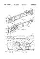
- FIG. 1is a perspective view of a self-locking snap-on suspension unit embodying the present invention, shown installed in an associated furniture case, wherein portions thereof have been exploded and broken away to reveal internal construction.
- FIG. 2is a side elevational view of outer housing portions of a pair of the suspension units, wherein the upper suspension housing is shown in a fully installed and locked position in the case, and the lower suspension housing is shown in a partially installed and unlocked position in the case.
- FIG. 3is a front perspective view of the outer housing portion of the suspension unit.
- FIG. 4is a rear perspective view of the outer housing.
- FIG. 5is an enlarged, fragmentary top plan view of the outer housing.
- FIG. 6is an enlarged, fragmentary rear elevational view of the outer housing.
- FIG. 7is a top plan view of the outer housing, shown in the partially installed and unlocked position in the case.
- FIG. 8is a top plan view of the outer housing, shown in the fully installed and locked position in the case.
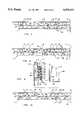
- FIG. 9is a vertical cross-section view of the suspension unit, shown mounted in the case adjacent an associated drawer.
- FIG. 10is a top plan view of the: outer housing, shown in the fully installed position in the case, wherein the lock arm has been deflected to its unlocked position to permit removing the suspension unit from the case.
- the reference numeral 1generally designates a self-locking, snap-on suspension unit embodying the present invention.
- Suspension unit 1is designed to mount a roll-out support, such as shelves, drawers, etc. in an associated furniture case, cabinet or the like.
- suspension unit 1is for supporting a drawer 2 in a lateral file case 3.
- Lateral file case 3is of the type having slotted interior uprights 4 and 5 located at the front and rear portions of case 3.
- Suspension unit 1includes an inner housing member 6 connected with drawer 2, and an outer housing member 7 operably connected with inner housing member 6 by any one of a variety of different arrangements, as described below, for smooth longitudinal sliding translation therebetween.
- the outer housing member 7has two set of prongs 8 and 9 (FIGS.
- a resiliently flexible lock arm 10is connected with outer housing member 7, and is configured to assume a normally outwardly protruding position, as best shown in FIGS. 4 and 5.
- Lock arm 10is laterally flexible into an inwardly retracted position, as shown in FIGS. 7 and 10, and is oriented generally opposite the direction of prongs 8 and 9, such that when prongs 8 and 9 are inserted into slotted uprights 4 and 5, lock arm 10 abuts an adjacent one of the uprights 5 to shift the same into the retracted position, as shown in FIG. 7.
- lock arm 10resiliently flexes back into its normally extended position against the side of the adjacent upright 5, as shown in FIG. 8, to positively prevent inadvertent removal of suspension unit 1 from case 3.
- the illustrated case 3(FIGS. 1 & 2) is for a two drawer lateral file cabinet 14, which includes a base 15, and interconnected sidewalls 16 and 17, back wall 18, and top 19.
- Each of the sidewalls 16 and 17has two uprights 4 and 5 extending along the interior surface thereof adjacent forward and rearward portions of case 3.
- Uprights 4 and 5serve to stiffen the sidewalls 16 and 17 of case 3, and facilitate mounting suspension units 1, and associated drawers 2 in the interior of case 3.
- the rear uprights 5also act as stops on the interior of case 3, which interface with the lock arms 10 on suspension units 1 in the manner described below. As best illustrated in FIGS.
- uprights 4 and 5have a substantially identical construction, wherein each includes portions with a generally U-shaped horizontal cross-sectional configuration, comprising opposite side flanges 22 and 23, and a central interconnecting web 24.
- Side flanges 23 and 24each has a generally L-shaped plan configuration, including a generally flat attachment arm 25 which is rigidly connected to the interior surface of the associated case sidewall 16, and a standoff arm 26 oriented perpendicular thereto.
- the web 24 of each of the uprights 4 and 5includes a plurality of horizontally oriented slots 29 therethrough, which are arranged in a vertically extending column, and are spaced generally equidistantly along the length of each of the uprights 4 and 5.
- slots 29are provided at one-half inch intervals along associated uprights 4 and 5, so that a drawer suspension unit 1 and associated drawer 2 can be positioned at any similar increment therealong.
- the illustrated drawer 2(FIG. 1) has a substantially conventional construction, comprising a front 35, opposite sidewalls 36 and 37, a rear wall 38, and a bottom (not shown), all of which are integrally interconnected to form a rigid, generally rectangular file drawer.
- a pull 39is integrally formed in drawer front 35 to facilitate opening the same.
- an inner housing member 6is shown preattached to sidewall 37 of drawer 2.
- the illustrated inner housing member 6(FIG. 9) has a conventional construction, and is in the form of a generally Z-shaped channel having a vertically oriented web 46, and a pair of horizontally oriented flanges 47. The outer end of upper flange 47 is formed upwardly to define a bearing race in which ball bearings 49 are retained.
- the web 46 of inner housing member 6includes horizontally oriented apertures through which fasteners 50 are closely received to detachably mount drawer 2 on inner housing member 6.
- the illustrated outer housing member 7(FIGS. 3-6) comprises a generally C-shaped channel 55 having a vertically oriented web 56, and two horizontally oriented flanges 57 and 58 extending therefrom.
- the upper flange 57has a downwardly protruding lip 59 extending along the free edge thereof, and the lower flange 58 similarly has a depending lip 60 extending along its free edge.
- An end tab 61is positioned at the rearward end of channel 55, and extends inwardly therefrom in between flanges 57 and 58.
- the channel flanges 57 and 58define opposite bearing races 62 in which ball bearings 64 (FIG. 9) are received to slidably interconnect inner housing member 6 with outer housing member 7, as described in greater detail below.
- suspension unit 1includes an intermediate channel member 68 (FIG. 9), which slidably interconnects inner housing member 6 and outer housing member 7 for smooth longitudinal translation therebetween.
- Intermediate channel member 68has a generally C-shaped configuration, comprising a vertically oriented web 69, and a pair of outwardly protruding flanges 70.
- Channel flanges 70form bearing races adjacent opposite ends thereof, which mate with ball bearings 64 to slidably interconnect inner housing member 6 with outer housing member 7.
- the present inventioncontemplates that other types of bearing arrangements can also be used to slidably interconnect inner housing member 6 with outer housing member 7.
- the prongs 8 and 9 incorporated into the illustrated outer housing member 7are formed integrally with the web, 56 of outer housing channel 55 adjacent opposite ends thereof, so as to provide a one-piece housing construction.
- the forward and rearward sets of prongs 8 and 9each include a pair of prongs having a generally similar hook-shaped side elevational configuration which protrudes outwardly toward case 3 from the outer housing channel 55. More specifically, each of the prongs 8 and 9 has a flat tab portion 76 which projects horizontally outwardly from the outer surface of channel web 56, and a forwardly extending tip portion 77.
- the forward prongs 8are punched from the web 56 of outer housing channel 55, and bent outwardly along the interior edges 80 of associated windows 81, so that prongs 8 are positioned mutually parallel, and fairly close together.
- the rear prongs 9are punched from the web 56 of outer housing channel 55, and bent outwardly about the outer edge 82 of associated windows 83, so that prongs 9 are positioned mutually parallel, yet are spaced further apart than the forward prongs 8.
- front prongs 8are spaced apart a distance equal to the distance between two adjacent upright slots 29, whereas rear prongs 9 are spaced apart a distance equal to the distance between three adjacent upright slots 29.
- Both sets of prongs 8 and 9are shaped to be closely received in the associated slots 29 in uprights 4 and 5, with the tip portions 77 oriented toward the front or open end of case 3, as illustrated in FIGS. 8 and 9.
- the tip portions 77 of prongs 8 and 9are shaped to abuttingly glide over the interior surfaces of upright webs 24 when the outer housing member 7 is shifted forwardly into the fully installed and locked position illustrated in FIG. 8.
- the illustrated lock arm 10has a generally trapezoidal front elevational configuration, and is also integrally formed with the web 56 of outer housing channel 55, so as to provide a one-piece housing construction.
- lock arm 10is punched from the web 56 of channel 55 forming window 84, and includes a flat base portion 85 positioned generally planar with channel web 56, and an outwardly protruding or laterally offset tip portion 86, which has a generally L-shaped plan configuration, as best shown in FIG. 5.
- the tip portion 86 of lock arm 10includes an outwardly protruding arm 87 and a flat end 88 disposed generally parallel with channel web 56.
- the end 88 of tip portion 86has an outermost end edge 89, which interfaces with one of the rear uprights 5 in case 3 in the manner described below to provide a self-locking construction for suspension unit 1, which prevents inadvertent removal of suspension unit 1 from case 3.
- the tip portion 86 of lock arm 10is oriented generally opposite prongs 8 and 9. In the example shown in FIGS. 7 and 8, the tip portion 86 of lock arm 10 points toward the closed rear or back of case 3, while the prongs 8 and 9 point toward the open front or face of case 3.
- Lock arm 10is resiliently flexible in a lateral direction, preferably by hand, to shift between the retracted unlocked position shown in FIG. 7, and the extended locked position shown in FIG. 8.
- outer housing member 7is formed from a single piece of sheet metal.
- suspension unit 1is installed in case 3 in the following manner.
- Suspension unit 1is first positioned at the elevation at which drawer 2 is desired to be mounted within case 3.
- the prongs 8 and 9 on outer housing member 7are then inserted into associated aligned slots 29 in vertical uprights 4 and 5, and pushed laterally inwardly.
- lock arm 10is laterally flexed into its inwardly retracted position by contact with upright web 24, as illustrated in FIG. 7, thereby permitting the suspension unit 1 to be shifted forwardly in a horizontal direction, with the tip portions 77 of prongs 8 and 9 engaging the interior surfaces of the adjacent upright webs 24.
- lock arm 10resiliently flexes back into its normally extended locked position against the forward side flange 26 of rear upright 5, as shown in FIG. 8, to positively prevent inadvertent removal of suspension unit 1 from case 3.
- the extended lock arm 10, and oppositely oriented prongs 8 and 9positively capture outer housing member 7 on the vertical uprights 4 and 5 of case 3.
- the inner housing member 6 associated with the installed outer housing member 7is then pulled forwardly, so as to access the mounting apertures through which fasteners 50 are inserted. Fasteners 50 are then mounted in the sides of drawer 2, thereby detachably, yet securely mounting drawer 2 on inner housing member 6.
- drawer 2is first removed from the inner housing member 6 of suspension unit 1 by removing fasteners 50.
- the usercan reach back into the interior of case 3, and manually flex the outer end 88 of lock arm 10 inwardly away from the sidewall 16 of case 3, in the manner shown by the arrow in FIG. 10.
- the outer housing member 7can be shifted longitudinally rearwardly to disengage prongs 8 and 9 from vertical uprights 4 and 5, and thereby permit removal of suspension unit 1 from case 3.
- suspension unit 1permits easy and quick assembly of a wide variety of different types of pull-out drawers, shelves, etc. in furniture cases, cabinets and the like.
- the resilient lock arm 10automatically shifts into its locked position when suspension unit 1 is fully installed within case 3, and provides a very positive type of locking action that prevents inadvertent removal and/or disengagement of the suspension unit 1 from case 3.
- the integral construction of lock arm 10 and prongs 8 and 9 with outer housing member 7permits economical manufacture, as well as an uncomplicated design. Since lock arm 10 can be manually shifted to its unlocked position, suspension unit 1 can be easily removed from case 3 without requiring any tools.
Landscapes
- Drawers Of Furniture (AREA)
Abstract
Description
Claims (20)
Priority Applications (1)
| Application Number | Priority Date | Filing Date | Title |
|---|---|---|---|
| US08/217,256US5470143A (en) | 1994-03-24 | 1994-03-24 | Self-locking snap-on suspension unit for furniture cabinets and the like |
Applications Claiming Priority (1)
| Application Number | Priority Date | Filing Date | Title |
|---|---|---|---|
| US08/217,256US5470143A (en) | 1994-03-24 | 1994-03-24 | Self-locking snap-on suspension unit for furniture cabinets and the like |
Publications (1)
| Publication Number | Publication Date |
|---|---|
| US5470143Atrue US5470143A (en) | 1995-11-28 |
Family
ID=22810291
Family Applications (1)
| Application Number | Title | Priority Date | Filing Date |
|---|---|---|---|
| US08/217,256Expired - LifetimeUS5470143A (en) | 1994-03-24 | 1994-03-24 | Self-locking snap-on suspension unit for furniture cabinets and the like |
Country Status (1)
| Country | Link |
|---|---|
| US (1) | US5470143A (en) |
Cited By (32)
| Publication number | Priority date | Publication date | Assignee | Title |
|---|---|---|---|---|
| US5775786A (en)* | 1997-02-05 | 1998-07-07 | Haworth, Inc. | Drawer slide |
| US5785401A (en)* | 1996-06-21 | 1998-07-28 | Herman Miller, Inc. | Vertical support for a slide mechanism in a cabinet |
| EP0818163A3 (en)* | 1996-07-09 | 1998-08-05 | Alfit Aktiengesellschaft | Drawer guide |
| US5851059A (en)* | 1997-03-04 | 1998-12-22 | Jonathan Manufacturing Corporation | Two-way extended travel slide suspension |
| US5906422A (en)* | 1997-12-04 | 1999-05-25 | Metal Fabricating Corporation | Insert panel support structure |
| NL1009545C2 (en)* | 1998-07-02 | 2000-01-07 | Regout Nv Thomas | Telescopic slide with suspension bracket. |
| GB2354933A (en)* | 1999-10-07 | 2001-04-11 | Accuride Int Ltd | Drawer with drawer slide quick release mechanism |
| US6217139B1 (en) | 1997-09-09 | 2001-04-17 | Kimball International, Inc. | Drawer for standardized furniture unit |
| US20040041500A1 (en)* | 2002-08-30 | 2004-03-04 | Richards-Wilcox, Inc. | Rotary filing cabinet with wardrobe |
| US20040263033A1 (en)* | 2003-03-28 | 2004-12-30 | Metal Fabricating Corporation | Cabinet runner side wall extension |
| US20050168115A1 (en)* | 2004-02-04 | 2005-08-04 | Brian Moon | Drawer cabinet storage kit |
| AT500722A1 (en)* | 2004-08-16 | 2006-03-15 | Blum Gmbh Julius | BEARING ELEMENT FOR FASTENING IN A FURNITURE BASKET |
| US20060273605A1 (en)* | 2005-06-01 | 2006-12-07 | Klaus Haspel | Stowage device for a vehicle luggage space |
| US20080067905A1 (en)* | 2006-09-18 | 2008-03-20 | Shape Corporation | Glide rail system for supporting sliding extension |
| US7452039B1 (en) | 2004-08-10 | 2008-11-18 | Metal Fabricating Corporation | Cabinet shelf with keyed slot |
| US20090195129A1 (en)* | 2006-07-05 | 2009-08-06 | Shinji Osawa | Rack device and incubator having the same |
| ITPD20100041A1 (en)* | 2010-02-12 | 2011-08-13 | Francom Spa | CHEST OF DRAWERS FOR VANS AND METHOD FOR HIS ASSEMBLY |
| USD643656S1 (en) | 2009-06-09 | 2011-08-23 | Metal Fabricating Corporation | Front wall of a cabinet shelf |
| US20120013235A1 (en)* | 2010-07-15 | 2012-01-19 | Oki Electric Industry Co., Ltd. | Slide rail structure |
| US8104850B2 (en) | 2007-05-30 | 2012-01-31 | Steelcase Inc. | Furniture storage unit |
| US8287060B1 (en) | 2003-10-22 | 2012-10-16 | Metal Fabricating Corporation | Cabinet shelf with keyed slot |
| US8322545B1 (en) | 2006-12-21 | 2012-12-04 | Metal Fabricating Corporation | Curved bin for shelf |
| US20130270988A1 (en)* | 2012-04-12 | 2013-10-17 | Cambro Manufacturing Company | Mobile Serving Cart with Adjustable Hinges |
| US20140042114A1 (en)* | 2012-08-07 | 2014-02-13 | Hon Hai Precision Industry Co., Ltd. | Electronic device rack |
| US20140175033A1 (en)* | 2012-12-26 | 2014-06-26 | Hon Hai Precision Industry Co., Ltd. | Electronic device rack |
| EP2764796A1 (en)* | 2013-02-08 | 2014-08-13 | King Slide Works Co., Ltd. | Slide rail assembly for use in rack system and reinforcement member thereof |
| US20160037918A1 (en)* | 2014-08-08 | 2016-02-11 | Duke Manufacturing Co. | Pan support apparatus |
| US9295327B2 (en)* | 2014-08-19 | 2016-03-29 | Haworth, Inc. | Side mounted drawer slide |
| WO2018068062A1 (en)* | 2016-10-07 | 2018-04-12 | Lockdowel, Inc. | Drawer slide locking button |
| US20190059587A1 (en)* | 2017-08-23 | 2019-02-28 | Clairson, Inc. | Shelf Brackets, Hang Rod Brackets, and Storage Systems Including the Same |
| US11234519B2 (en)* | 2010-06-30 | 2022-02-01 | Carefusion 303, Inc. | Configurable cabinet for hanging and shelved items |
| EP4125311A1 (en)* | 2021-07-26 | 2023-02-01 | King Slide Works Co., Ltd. | Supporting device |
Citations (24)
| Publication number | Priority date | Publication date | Assignee | Title |
|---|---|---|---|---|
| US1508259A (en)* | 1919-10-27 | 1924-09-09 | Ion A Stafford | Metal desk |
| US3119643A (en)* | 1962-07-12 | 1964-01-28 | Blickman Inc | Laboratory cabinet |
| US3377115A (en)* | 1967-02-27 | 1968-04-09 | Simmons Co | Drawer construction |
| US3572874A (en)* | 1968-10-23 | 1971-03-30 | Schaefer Gmbh Fritz | Metal cabinets |
| US3677615A (en)* | 1970-03-16 | 1972-07-18 | Leslie Gordon Hudson | Drawer units and runners therefor |
| US3712698A (en)* | 1970-11-12 | 1973-01-23 | Miller H Inc | Structural support system for drawers and the like |
| US3716284A (en)* | 1971-05-17 | 1973-02-13 | J Vogt | Vertically-adjustable drawer suspension |
| US3771849A (en)* | 1972-03-06 | 1973-11-13 | Standard Precision Inc | Bayonet-mounting means for sliding drawers |
| US3923347A (en)* | 1972-10-12 | 1975-12-02 | Wright Barry Corp | Suspension latch |
| US4147393A (en)* | 1977-12-16 | 1979-04-03 | Knape & Vogt Manufacturing Co. | Drawer slide mount employing a slide element and cooperative clip |
| US4157228A (en)* | 1977-07-14 | 1979-06-05 | Hammerschlag Peter G | Locking tab for hook-in type shelving |
| US4183596A (en)* | 1979-01-17 | 1980-01-15 | Bowie Mfg. Co. | Two way travel drawer slide |
| US4469384A (en)* | 1979-11-07 | 1984-09-04 | Jacmorr Manufacturing Limited | Three part slide |
| US4566743A (en)* | 1984-06-11 | 1986-01-28 | Kimball International, Inc. | Drawer slide clip |
| US4575164A (en)* | 1984-05-18 | 1986-03-11 | Carter-Hoffman Corporation | Heavy duty universal adjustable slider for food service cart |
| US4681289A (en)* | 1986-03-31 | 1987-07-21 | Knape & Vogt Manufacturing Company | Side mounting bracket for drawer slide |
| US4681381A (en)* | 1986-10-16 | 1987-07-21 | Waterloo Industries, Inc. | Removable drawer slide and interlock with drawer |
| US4792195A (en)* | 1987-08-06 | 1988-12-20 | Kidde Holding, Inc. | Drawer support system |
| US4834555A (en)* | 1985-05-10 | 1989-05-30 | Alfred Grass Ges.M.B.H. Metallwarenfabrik | Fixture for the attachment of a guide rail to the body of a piece of furniture |
| US4872734A (en)* | 1987-06-22 | 1989-10-10 | Robert Rechberg | Drawer slides with self-actuating latching systems |
| US4913580A (en)* | 1989-02-23 | 1990-04-03 | Suncast Corporation | Releasable connector assembly |
| US4928834A (en)* | 1988-06-06 | 1990-05-29 | Vesper Corporation | Safety beam lock |
| US4998828A (en)* | 1989-10-02 | 1991-03-12 | General Devices Co., Inc. | Over and under telescoping slide assembly |
| US5211461A (en)* | 1992-04-10 | 1993-05-18 | Artromick International, Inc. | Vertically adjustable extension drawers |
- 1994
- 1994-03-24USUS08/217,256patent/US5470143A/ennot_activeExpired - Lifetime
Patent Citations (24)
| Publication number | Priority date | Publication date | Assignee | Title |
|---|---|---|---|---|
| US1508259A (en)* | 1919-10-27 | 1924-09-09 | Ion A Stafford | Metal desk |
| US3119643A (en)* | 1962-07-12 | 1964-01-28 | Blickman Inc | Laboratory cabinet |
| US3377115A (en)* | 1967-02-27 | 1968-04-09 | Simmons Co | Drawer construction |
| US3572874A (en)* | 1968-10-23 | 1971-03-30 | Schaefer Gmbh Fritz | Metal cabinets |
| US3677615A (en)* | 1970-03-16 | 1972-07-18 | Leslie Gordon Hudson | Drawer units and runners therefor |
| US3712698A (en)* | 1970-11-12 | 1973-01-23 | Miller H Inc | Structural support system for drawers and the like |
| US3716284A (en)* | 1971-05-17 | 1973-02-13 | J Vogt | Vertically-adjustable drawer suspension |
| US3771849A (en)* | 1972-03-06 | 1973-11-13 | Standard Precision Inc | Bayonet-mounting means for sliding drawers |
| US3923347A (en)* | 1972-10-12 | 1975-12-02 | Wright Barry Corp | Suspension latch |
| US4157228A (en)* | 1977-07-14 | 1979-06-05 | Hammerschlag Peter G | Locking tab for hook-in type shelving |
| US4147393A (en)* | 1977-12-16 | 1979-04-03 | Knape & Vogt Manufacturing Co. | Drawer slide mount employing a slide element and cooperative clip |
| US4183596A (en)* | 1979-01-17 | 1980-01-15 | Bowie Mfg. Co. | Two way travel drawer slide |
| US4469384A (en)* | 1979-11-07 | 1984-09-04 | Jacmorr Manufacturing Limited | Three part slide |
| US4575164A (en)* | 1984-05-18 | 1986-03-11 | Carter-Hoffman Corporation | Heavy duty universal adjustable slider for food service cart |
| US4566743A (en)* | 1984-06-11 | 1986-01-28 | Kimball International, Inc. | Drawer slide clip |
| US4834555A (en)* | 1985-05-10 | 1989-05-30 | Alfred Grass Ges.M.B.H. Metallwarenfabrik | Fixture for the attachment of a guide rail to the body of a piece of furniture |
| US4681289A (en)* | 1986-03-31 | 1987-07-21 | Knape & Vogt Manufacturing Company | Side mounting bracket for drawer slide |
| US4681381A (en)* | 1986-10-16 | 1987-07-21 | Waterloo Industries, Inc. | Removable drawer slide and interlock with drawer |
| US4872734A (en)* | 1987-06-22 | 1989-10-10 | Robert Rechberg | Drawer slides with self-actuating latching systems |
| US4792195A (en)* | 1987-08-06 | 1988-12-20 | Kidde Holding, Inc. | Drawer support system |
| US4928834A (en)* | 1988-06-06 | 1990-05-29 | Vesper Corporation | Safety beam lock |
| US4913580A (en)* | 1989-02-23 | 1990-04-03 | Suncast Corporation | Releasable connector assembly |
| US4998828A (en)* | 1989-10-02 | 1991-03-12 | General Devices Co., Inc. | Over and under telescoping slide assembly |
| US5211461A (en)* | 1992-04-10 | 1993-05-18 | Artromick International, Inc. | Vertically adjustable extension drawers |
Cited By (52)
| Publication number | Priority date | Publication date | Assignee | Title |
|---|---|---|---|---|
| US5785401A (en)* | 1996-06-21 | 1998-07-28 | Herman Miller, Inc. | Vertical support for a slide mechanism in a cabinet |
| US6042206A (en)* | 1996-06-21 | 2000-03-28 | Herman Miller, Inc. | Vertical support for a slide mechanism in a cabinet |
| US6123402A (en)* | 1996-06-21 | 2000-09-26 | Herman Miller, Inc. | Cabinet having a support for a slide mechanism |
| EP0818163A3 (en)* | 1996-07-09 | 1998-08-05 | Alfit Aktiengesellschaft | Drawer guide |
| AT411005B (en)* | 1996-07-09 | 2003-09-25 | Alfit Ag | DRAWER GUIDE |
| EP0861621A1 (en)* | 1997-02-05 | 1998-09-02 | Haworth, Inc. | Drawer slide |
| US5775786A (en)* | 1997-02-05 | 1998-07-07 | Haworth, Inc. | Drawer slide |
| US5851059A (en)* | 1997-03-04 | 1998-12-22 | Jonathan Manufacturing Corporation | Two-way extended travel slide suspension |
| US6217139B1 (en) | 1997-09-09 | 2001-04-17 | Kimball International, Inc. | Drawer for standardized furniture unit |
| US6428128B1 (en) | 1997-09-09 | 2002-08-06 | Kimball International, Inc. | Drawer for standardized furniture unit |
| US5906422A (en)* | 1997-12-04 | 1999-05-25 | Metal Fabricating Corporation | Insert panel support structure |
| NL1009545C2 (en)* | 1998-07-02 | 2000-01-07 | Regout Nv Thomas | Telescopic slide with suspension bracket. |
| WO2000001278A1 (en)* | 1998-07-02 | 2000-01-13 | Thomas Regout B.V. | Telescopic guide with suspension bracket |
| GB2354933A (en)* | 1999-10-07 | 2001-04-11 | Accuride Int Ltd | Drawer with drawer slide quick release mechanism |
| US6817686B1 (en) | 1999-10-07 | 2004-11-16 | Accuride International Limited | Drawer with drawer slide quick-release mechanism |
| US20040041500A1 (en)* | 2002-08-30 | 2004-03-04 | Richards-Wilcox, Inc. | Rotary filing cabinet with wardrobe |
| US7306300B2 (en) | 2003-03-28 | 2007-12-11 | Metal Fabricating Corporation | Cabinet runner side wall extension |
| US20040263033A1 (en)* | 2003-03-28 | 2004-12-30 | Metal Fabricating Corporation | Cabinet runner side wall extension |
| US8287060B1 (en) | 2003-10-22 | 2012-10-16 | Metal Fabricating Corporation | Cabinet shelf with keyed slot |
| US20050168115A1 (en)* | 2004-02-04 | 2005-08-04 | Brian Moon | Drawer cabinet storage kit |
| US7452039B1 (en) | 2004-08-10 | 2008-11-18 | Metal Fabricating Corporation | Cabinet shelf with keyed slot |
| AT500722A1 (en)* | 2004-08-16 | 2006-03-15 | Blum Gmbh Julius | BEARING ELEMENT FOR FASTENING IN A FURNITURE BASKET |
| US20070145867A1 (en)* | 2004-08-16 | 2007-06-28 | Ingo Gasser | Support element for securing in a furniture carcass |
| US8025348B2 (en) | 2004-08-16 | 2011-09-27 | Julius Blum Gmbh | Support element for securing in a furniture carcass |
| AT500722B1 (en)* | 2004-08-16 | 2009-06-15 | Blum Gmbh Julius | BEARING ELEMENT FOR FASTENING IN A FURNITURE BASKET |
| US20060273605A1 (en)* | 2005-06-01 | 2006-12-07 | Klaus Haspel | Stowage device for a vehicle luggage space |
| US20090195129A1 (en)* | 2006-07-05 | 2009-08-06 | Shinji Osawa | Rack device and incubator having the same |
| US8136899B2 (en)* | 2006-07-05 | 2012-03-20 | Sanyo Electric Co., Ltd. | Rack device and incubator having the same |
| EP2036456A4 (en)* | 2006-07-05 | 2012-05-30 | Sanyo Electric Co | SHELF DEVICE AND INCUBATOR HAVING THE SAME |
| WO2008036655A3 (en)* | 2006-09-18 | 2009-05-14 | Shape Corp | Glide rail system for supporting sliding extension |
| US20080067905A1 (en)* | 2006-09-18 | 2008-03-20 | Shape Corporation | Glide rail system for supporting sliding extension |
| US8322545B1 (en) | 2006-12-21 | 2012-12-04 | Metal Fabricating Corporation | Curved bin for shelf |
| US8104850B2 (en) | 2007-05-30 | 2012-01-31 | Steelcase Inc. | Furniture storage unit |
| USD643656S1 (en) | 2009-06-09 | 2011-08-23 | Metal Fabricating Corporation | Front wall of a cabinet shelf |
| EP2359715A2 (en) | 2010-02-12 | 2011-08-24 | Francom S.P.A. | Drawer unit for vans and method for its assembly |
| ITPD20100041A1 (en)* | 2010-02-12 | 2011-08-13 | Francom Spa | CHEST OF DRAWERS FOR VANS AND METHOD FOR HIS ASSEMBLY |
| US11234519B2 (en)* | 2010-06-30 | 2022-02-01 | Carefusion 303, Inc. | Configurable cabinet for hanging and shelved items |
| US20120013235A1 (en)* | 2010-07-15 | 2012-01-19 | Oki Electric Industry Co., Ltd. | Slide rail structure |
| JP2012038294A (en)* | 2010-07-15 | 2012-02-23 | Oki Electric Ind Co Ltd | Slide rail structure and automatic transaction device |
| CN102393981A (en)* | 2010-07-15 | 2012-03-28 | 冲电气工业株式会社 | Slide rail structure and automatic business device |
| US20130270988A1 (en)* | 2012-04-12 | 2013-10-17 | Cambro Manufacturing Company | Mobile Serving Cart with Adjustable Hinges |
| US9161620B2 (en)* | 2012-04-12 | 2015-10-20 | Cambro Manufacturing Company | Mobile serving cart with adjustable hinges |
| US20140042114A1 (en)* | 2012-08-07 | 2014-02-13 | Hon Hai Precision Industry Co., Ltd. | Electronic device rack |
| US20140175033A1 (en)* | 2012-12-26 | 2014-06-26 | Hon Hai Precision Industry Co., Ltd. | Electronic device rack |
| EP2764796A1 (en)* | 2013-02-08 | 2014-08-13 | King Slide Works Co., Ltd. | Slide rail assembly for use in rack system and reinforcement member thereof |
| US20160037918A1 (en)* | 2014-08-08 | 2016-02-11 | Duke Manufacturing Co. | Pan support apparatus |
| US9788652B2 (en)* | 2014-08-08 | 2017-10-17 | Duke Manufacturing Co. | Pan support apparatus |
| US9295327B2 (en)* | 2014-08-19 | 2016-03-29 | Haworth, Inc. | Side mounted drawer slide |
| WO2018068062A1 (en)* | 2016-10-07 | 2018-04-12 | Lockdowel, Inc. | Drawer slide locking button |
| US20190059587A1 (en)* | 2017-08-23 | 2019-02-28 | Clairson, Inc. | Shelf Brackets, Hang Rod Brackets, and Storage Systems Including the Same |
| EP4125311A1 (en)* | 2021-07-26 | 2023-02-01 | King Slide Works Co., Ltd. | Supporting device |
| US12055169B2 (en) | 2021-07-26 | 2024-08-06 | King Slide Works Co., Ltd. | Supporting device |
Similar Documents
| Publication | Publication Date | Title |
|---|---|---|
| US5470143A (en) | Self-locking snap-on suspension unit for furniture cabinets and the like | |
| EP0861621B1 (en) | Drawer slide | |
| EP0977504B1 (en) | Drawer slide undermount bracket with flexible locking tab | |
| US4423914A (en) | Drawer slide locking lever | |
| US5695163A (en) | Wall-mounted shelving system or similar article | |
| US4067632A (en) | Drawer slide | |
| US7497533B2 (en) | Shelves, resilient drawer stops, and drawer brackets for supporting shelves and drawers | |
| CN101511228B (en) | drawer | |
| US7021730B2 (en) | Drawer bracket | |
| JPH08299077A (en) | Shock absorbing separation latch for sliding apparatus for drawer | |
| US4193649A (en) | Anti-tilt bracket and clip assembly for adjustable drawers or similar articles | |
| KR930003574Y1 (en) | Extension pull-out guide assembly for drawers | |
| US20040227441A1 (en) | Rail assembly for attaching server to cabinet | |
| US4908917A (en) | Slide and latch mechanism | |
| US3177988A (en) | Refrigerator cabinet construction | |
| US4436357A (en) | Pull-out guide assembly for drawers, shelves or the like | |
| US4475778A (en) | Drawer suspension system | |
| CA1163667A (en) | Drawers and drawer runners | |
| CN108720379A (en) | Drawer sliding rail component and refrigeration equipment | |
| GB2140279A (en) | Pull-out guide for drawers | |
| US4315661A (en) | Drawer slide | |
| CA2047481A1 (en) | Drawer and drawer suspension system | |
| EP2322057A1 (en) | Drawer assembly | |
| AU2010212440A1 (en) | Drawer assembly | |
| CN214532500U (en) | Self-locking partition plate of safe |
Legal Events
| Date | Code | Title | Description |
|---|---|---|---|
| AS | Assignment | Owner name:STEELCASE, INC., MICHIGAN Free format text:ASSIGNMENT OF ASSIGNORS INTEREST;ASSIGNOR:GILL, JOHN F.;REEL/FRAME:006939/0400 Effective date:19940323 | |
| STCF | Information on status: patent grant | Free format text:PATENTED CASE | |
| FPAY | Fee payment | Year of fee payment:4 | |
| AS | Assignment | Owner name:STEELCASE DEVELOPMENT INC., A CORPORATION OF MICHI Free format text:ASSIGNMENT OF ASSIGNORS INTEREST;ASSIGNOR:STEELCASE INC., A CORPORATION OF MICHIGAN;REEL/FRAME:010188/0385 Effective date:19990701 | |
| FEPP | Fee payment procedure | Free format text:PAYOR NUMBER ASSIGNED (ORIGINAL EVENT CODE: ASPN); ENTITY STATUS OF PATENT OWNER: LARGE ENTITY | |
| FPAY | Fee payment | Year of fee payment:8 | |
| FEPP | Fee payment procedure | Free format text:PAYER NUMBER DE-ASSIGNED (ORIGINAL EVENT CODE: RMPN); ENTITY STATUS OF PATENT OWNER: LARGE ENTITY Free format text:PAYOR NUMBER ASSIGNED (ORIGINAL EVENT CODE: ASPN); ENTITY STATUS OF PATENT OWNER: LARGE ENTITY | |
| FPAY | Fee payment | Year of fee payment:12 |