US5469855A - Continuous temperature monitor - Google Patents
Continuous temperature monitorDownload PDFInfo
- Publication number
- US5469855A US5469855AUS08/281,766US28176694AUS5469855AUS 5469855 AUS5469855 AUS 5469855AUS 28176694 AUS28176694 AUS 28176694AUS 5469855 AUS5469855 AUS 5469855A
- Authority
- US
- United States
- Prior art keywords
- temperature
- ear
- ear canal
- radiation detector
- plug structure
- Prior art date
- Legal status (The legal status is an assumption and is not a legal conclusion. Google has not performed a legal analysis and makes no representation as to the accuracy of the status listed.)
- Expired - Lifetime
Links
Images


Classifications
- G—PHYSICS
- G01—MEASURING; TESTING
- G01J—MEASUREMENT OF INTENSITY, VELOCITY, SPECTRAL CONTENT, POLARISATION, PHASE OR PULSE CHARACTERISTICS OF INFRARED, VISIBLE OR ULTRAVIOLET LIGHT; COLORIMETRY; RADIATION PYROMETRY
- G01J5/00—Radiation pyrometry, e.g. infrared or optical thermometry
- G01J5/02—Constructional details
- G01J5/04—Casings
- G01J5/049—Casings for tympanic thermometers
- G—PHYSICS
- G01—MEASURING; TESTING
- G01J—MEASUREMENT OF INTENSITY, VELOCITY, SPECTRAL CONTENT, POLARISATION, PHASE OR PULSE CHARACTERISTICS OF INFRARED, VISIBLE OR ULTRAVIOLET LIGHT; COLORIMETRY; RADIATION PYROMETRY
- G01J5/00—Radiation pyrometry, e.g. infrared or optical thermometry
- G01J5/02—Constructional details
- G01J5/06—Arrangements for eliminating effects of disturbing radiation; Arrangements for compensating changes in sensitivity
- G01J5/064—Ambient temperature sensor; Housing temperature sensor; Constructional details thereof
- G—PHYSICS
- G01—MEASURING; TESTING
- G01J—MEASUREMENT OF INTENSITY, VELOCITY, SPECTRAL CONTENT, POLARISATION, PHASE OR PULSE CHARACTERISTICS OF INFRARED, VISIBLE OR ULTRAVIOLET LIGHT; COLORIMETRY; RADIATION PYROMETRY
- G01J5/00—Radiation pyrometry, e.g. infrared or optical thermometry
- G01J5/02—Constructional details
- G01J5/08—Optical arrangements
- G01J5/0818—Waveguides
- G—PHYSICS
- G01—MEASURING; TESTING
- G01J—MEASUREMENT OF INTENSITY, VELOCITY, SPECTRAL CONTENT, POLARISATION, PHASE OR PULSE CHARACTERISTICS OF INFRARED, VISIBLE OR ULTRAVIOLET LIGHT; COLORIMETRY; RADIATION PYROMETRY
- G01J5/00—Radiation pyrometry, e.g. infrared or optical thermometry
- G01J5/02—Constructional details
- G01J5/08—Optical arrangements
- G01J5/0893—Arrangements to attach devices to a pyrometer, i.e. attaching an optical interface; Spatial relative arrangement of optical elements, e.g. folded beam path
- G—PHYSICS
- G01—MEASURING; TESTING
- G01J—MEASUREMENT OF INTENSITY, VELOCITY, SPECTRAL CONTENT, POLARISATION, PHASE OR PULSE CHARACTERISTICS OF INFRARED, VISIBLE OR ULTRAVIOLET LIGHT; COLORIMETRY; RADIATION PYROMETRY
- G01J5/00—Radiation pyrometry, e.g. infrared or optical thermometry
- G01J5/10—Radiation pyrometry, e.g. infrared or optical thermometry using electric radiation detectors
- G01J5/12—Radiation pyrometry, e.g. infrared or optical thermometry using electric radiation detectors using thermoelectric elements, e.g. thermocouples
- G01J5/14—Electrical features thereof
- G01J5/16—Arrangements with respect to the cold junction; Compensating influence of ambient temperature or other variables
Definitions
- Non-contact temperature measurement devices using thermopile sensors to determine a subject's body temperatureare a reliable alternative to traditional sublingual thermometers. These tympanic temperature devices obtain a measurement of the tympanic membrane in a subject's ear by the detection of infrared radiation. The tympanic membrane area is considered to provide a highly accurate representation of a subject's core temperature, and infrared temperature measurements using a thermopile are extremely rapid.
- a hand-held radiation detector suitable for tympanic temperature measurementis illustrated in U.S. Pat. No. 4,993,419.
- the detectorobtains tympanic temperature measurements from the output of a thermopile mounted in an extension from a housing.
- the housinghas a temperature display and supports the electronics for responding to sensed radiation from the tympanic membrane.
- the extensionextends at about a fifteen degree angle from the housing and has the appearance of a conventional otoscope.
- U.S. Pat. No. 4,602,642 to O'Hara et alThis device comprises a probe unit having a handle and a head assembly terminating in a probe which is inserted into the external ear canal to take a subject's temperature.
- the head assemblycontains an infrared sensitive thermopile detector for measuring radiation from the tympanic membrane.
- the probe unitis attached to a chopper unit by a cord, and both units must be physically mated between temperature readings for recalibration.
- the present inventiondiscloses various features of a continuous temperature monitor particularly suited for monitoring of ear canal temperature or tympanic temperature over an extended period of time. Examples include the continuous monitoring of a subject's body temperature during exposure to extreme environmental conditions or during physical exertion. Another example would be continuous monitoring of a patient's temperature in a hospital environment.
- tympanic temperature devicesoperate on the principle that the tympanic membrane must be within line-of-sight of the sensor.
- the tympanic membraneis not readily visible upon viewing a subject's ear because the human ear canal is curved.
- existing devicesforcibly straighten a portion of the ear canal to view the tympanic membrane.
- the osseous section of the ear canalconsists of inflexible bone, straightening is achieved on a portion of the ear canal near the concha which consists of soft, flexible cartilage.
- a tympanic temperature monitorhas a remote assembly comprising a radiation detector having thermopile mounted to view a tympanic membrane and a plug structure shaped to fit in the concha region of an ear.
- the remote sensor assemblyfits comfortably in a subject's ear to allow for continuous monitoring.
- the remote assemblyfurther comprises a flexible extension which deflects upon insertion into an ear canal to conform to the contours therein and connects the radiation detector with the plug structure.
- a hollow, barbed anchormay surround a portion of the flexible extension adjacent to the plug structure. Once the remote sensor assembly is inserted, the anchor ensures that it will remain in the ear without backing out.
- an ear-claspmay be attached to the remote assembly to secure it within an ear canal. The ear-clasp is shaped to fit behind a subject's ear and has a clip which is secured over the ear to ensure that the remote assembly remains in the ear.
- the flexible extensionconforms to the natural shape of either an adult's ear canal or a child's ear canal.
- the flexible extensionshould be at least 8 mm in length in order that the radiation detector be located beyond the three-dimensional bend in a typical ear canal to provide a clear view of the tympanic membrane.
- the combined length of the radiation detector and the flexible extensionis typically about 19 mm. Since an adult subject will usually experience discomfort if a device is inserted beyond 20 mm into the ear canal, the overall length of the sensor and flexible extension should be no more than 20 mm.
- the aforementioned extensionmay be a semi-rigid structure which is preshaped to fit in an ear canal. However, some minimal distortion of the ear canal is required for this embodiment during insertion due to the natural curvature of the ear canal. Once inserted though, the preshaped semi-rigid extension fits comfortably in an ear canal.
- a disposable elementmay be used over the remote sensor assembly.
- the elementis sanitary and serves as a lubricant to aid insertion or removal of the assembly.
- the elementalso acts as a cushion for comfortable positioning of the assembly.
- the disposable elementis a flat sheet of plastic, such as polyethylene, transparent to infrared radiation. The flat sheet is sufficiently stretchable to form a neat fit over the distal end of the remote sensor assembly.
- a ring of soft, flexible material such as cottonmay be attached to one side of the disposable element.
- the ringis translated over the radiation detector and surrounds a portion of the flexible extension in close proximity to the aft edge of the radiation detector.
- the outer radius of the ringis preferrably greater than the radius of the radiation detector, so a properly positioned ring provides additional comfort to the subject during insertion and removal of the remote assembly. Additionally, the ring minimizes discomfort to a subject when the radiation detector is oriented in the ear canal for the thermopile to view the tympanic membrane.
- An adapter shaped to fit in the concha region of a subject's earmay be used with the disposable element (which also may have a ring attached thereto) to secure the remote sensor assembly in a subject having an uncommonly short ear canal such as a child.
- the adaptermay be installed on the remote sensor assembly before or after the disposable element.
- the disposable elementis first placed over the remote sensor assembly.
- the adapteris then translated along the plastic sheet over the length of the flexible extension and positioned adjacent to the plug structure. Since the adapter has a shape which resembles a hollow version of the plug structure, it is positioned to completely cover the distal end of the plug structure. Once it is in place, the adapter has sufficient thickness to reduce the length that the flexible extension extends into an ear canal. With a number of adapters with varying thickness available, a single remote sensor assembly may fit comfortably within any ear canal.
- the preferred radiation detector of this inventioncomprises a tympanic temperature sensor which is smaller than existing devices in order to fit comfortably inside an ear canal for extended periods of time.
- the traditional sensorcan is not used and the gas-filled space within the sensor is reduced in size.
- the tympanic sensordetects tympanic radiation using a thermopile mounted to a film.
- the filmis suspended across an opening in a pair of high thermal conductivity rings such as beryllium oxide.
- a windowis mounted directly onto the first beryllium oxide ring.
- the reduced space located behind the window and defined by the ringsis filled with air instead of low thermal conductivity xenon gas.
- thermocouple for sensing the cold junction temperature of the thermopileis also mounted directly onto the first beryllium oxide ring. Instead of enclosing the tympanic sensor with a can, a thin layer of non-thermally conductive potting material covers the sensor body. A coating of silver paint is applied to the potting material to electrically shield the sensor, and a second thin layer of non-thermally conductive potting material covers the silver paint. By using non-thermally conductive potting material, the sensor is thermally isolated with respect to the external environment. Thus, the thermopile and the thermocouple will provide stable output voltages since the potting material protects both devices from thermal gradients within the ear canal.
- thermocoupleis connected electrically in series with the thermopile such that the output voltages of the thermocouple and thermopile may be combined to produce a total output signal.
- the thermopileprovides an output voltage indicative of the temperature differential between the tympanic membrane and the thermopile cold junction.
- the thermocouplehas its hot junction thermally coupled to the cold junction of the thermopile via the first beryllium oxide ring.
- the cold junction of the thermocoupleis thermally coupled to a reference mass of high thermal conductivity potting material located in the plug structure. Accordingly, the thermocouple provides an output voltage indicative of the temperature differential between the cold junction of the thermopile and the mass.
- the temperature of the massis monitored by an absolute temperature device such as a thermistor. Since the total output voltage of the thermopile and the thermocouple in series represents the difference in temperature between the tympanic membrane and an absolute temperature, the tympanic temperature can be determined.
- an absolute temperature devicesuch as a thermistor. Since the total output voltage of the thermopile and the thermocouple in series represents the difference in temperature between the tympanic membrane and an absolute temperature, the tympanic temperature can be determined.
- thermopile and the thermocoupleThe combined thermal mass of the thermopile and the thermocouple is relatively small, so the corresponding thermal capacitance is small. Since the thermal resistance of the thermopile and the thermocouple is also small due to the low thermal resistance of the beryllium oxide rings, the RC time constant for the two devices is small. In contrast, the entire tympanic sensor assembly has large thermal resistance, specifically between the thermopile cold junction and the external environment, due to the layers of non-thermally conductive potting material and the small electrical leads. Thus, the RC time constant of the entire tympanic sensor assembly is relatively large compared to the RC time constant for the thermopile in combination with the thermocouple. Consequently, after the sensor is inserted into an ear canal, the thermopile and the thermocouple can accurately track the tympanic temperature unaffected by thermal gradients in the ear canal.
- the plug structureis made of a high thermal conductivity material and may contain an internal strip of thermal insulation material.
- the insulating materialthermally isolates the distal portion of the plug structure from the portion containing the plug electronics.
- a mass of high thermal conductivity potting materialcomprising a preferred thermistor is located in the distal end of the plug structure. As stated previously, the thermistor determines the absolute temperature of distal portion of the plug structure.
- the cold junction of the thermocoupleis thermally coupled to the thermistor and the mass of potting material which serves as a temperature reference for the thermocouple.
- the thermocouple cold junction temperature referenceis remotely located with respect to the thermopile.
- the relatively large thermistoris not positioned in the radiation detector assembly, so size of the latter can be kept to a minimun for both comfort to a subject and speed of response.
- the tympanic temperature monitoralso comprises a housing which is connected to the remote assembly via a cable.
- an ear canal temperature monitorcomprises a remote assembly having a radiation detector and an ear-piece shaped to fit behind a subject's ear.
- the ear-piececontains the electronics assembly contained in the plug structure of the other embodiment.
- a clip located on the ear-pieceprevents the remote assembly from backing out of a subject's ear during monitoring.
- the flexible extensionconnects the radiation detector and the ear-piece.
- a hollow adaptersurrounds a portion of the flexible extension and is shaped to fit in the concha region of an ear.
- the depth of penetration of the radiation detector into an ear canalis adjustable. More specifically, a stop ring is positioned on the flexible extension to secure the adapter and to prevent the extension from extending into the ear beyond an intended length.
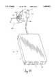
- FIG. 1Aillustrates a tympanic temperature monitor in accordance with the present invention.
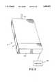
- FIG. 1Billustrates an ear canal temperature monitor in accordance with another embodiment of the invention.
- FIG. 2Ais a view projected from three-dimensions of a human right ear canal with the remote assembly of FIG. 1A mounted therein.
- FIG. 2Billustrates the remote sensor assembly of FIG. 2A having a disposable element, an adapter and an ear-clasp.
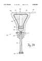
- FIG. 3Ais a cross-sectional view of the temperature sensor of FIGS. 1A and 1B.
- FIG. 3Bis a cross-sectional view of the remote assembly of the remote sensor assembly of FIG. 1A.
- FIG. 3Cis a perspective view of the beryllium oxide rings of the temperature sensor of FIG. 3A.
- FIG. 4illustrates the mass of thermally conductive potting material located in the plug structure of the remote sensor assembly of FIG. 3B.
- FIG. 5Ais a schematic representation of the electronic circuitry of the remote sensor assembly of FIGS. 1A and 1B.
- FIG. 5Bis a block diagram of the electronic circuitry of the housing unit of FIGS. 1A and 1B.
- FIG. 6Ais a schematic representation of an alternative configuration of the remote sensor assembly electronics of FIG. 5A.
- FIG. 6Bis a schematic representation of another alternative configuration of the remote sensor assembly electronics of FIG. 5A.
- FIG. 7Ais a schematic representation of an alternative implementation of the tympanic temperature electronics of FIGS. 5A and 5B.
- FIG. 7Bis a schematic representation of an alternative display configuration of the display electronics of FIG. 7A.
- FIG. 8illustrates a boot positioned on the housing of FIG. 1 during a calibration procedure.
- FIGS. 9A-Care flow charts of the system firmware.
- the tympanic temperature monitor 12 of FIG. 1Aincludes a flat housing 14 with a digital display 16 for continuous display of a subject's tympanic temperature.
- the display 16is a dual display which also provides for continuous display of the rate of change of tympanic temperature.
- the displaymay be located anywhere on the housing, although it is positioned on the end in the preferred embodiment.
- the instrumentinitially makes an accurate measurement of temperature when inserted into the ear canal and allows for continuous temperature monitoring without discomfort to the subject.
- a thermopile radiation sensoris contained within a remote assembly 18 which is connected to the housing 14 by a cable 48. The remote assembly 18 moves freely in space with respect to the housing 14 constrained only by the length of the cable 48.
- An on/off switch 22is positioned on the housing.
- a plug structure 24is covered with a soft molded silicon material and tapered toward its distal end so that it may fit comfortably within the concha region of an ear.
- the plug structure 24is connected to a temperature sensor 30 by a flexible extension 20.
- the flexible extension 20bends to conform to the contours of the ear canal.
- a hollow rubber barbed anchor resembling an ear plug 26may surround the portion of the flexible extension 20 adjacent to the plug structure 24.
- the plug structureprevents the remote assembly 18 from being inserted too far into the ear canal so as to cause discomfort and also contains electronics which provide signals to the housing that are manipulated to produce tympanic temperature measurements. Once the remote assembly 18 is inserted, the anchor 26 causes it to remain in the ear canal without backing out.
- the flexible extension 20bends to the contours of an ear canal 19 so that the tympanic sensor 30 can remain in the ear canal for extended time periods without discomfort.
- the flexible extensionis a shielded cable which electrically connects the sensor 30 and the plug structure 24.
- high thermal impedance leads having small diametersare preferred.
- the plug structurewhich fits snugly in the concha region of a typical ear, ensures that the remote assembly cannot be inserted too far into a subject's ear canal.
- the plug structureis shaped to fit comfortably in the concha region so that the entire remote assembly can remain in a subject's ear canal for a long period of time without discomfort.
- the hollow anchor 26may surround a portion of the flexible extension adjacent to the plug structure.
- the anchoris composed of a soft rubber-like material and has barbed fins 27 extending from its main body. The barbed fins on the anchor further secure the entire remote assembly in a subject's ear.
- the flexible extension 20is a semi-rigid structure which is preshaped to fit in an ear canal. Some distortion of an ear canal is required, however, to insert the sensor in this embodiment due to the three-dimensional curve in the ear canal.
- An adult's ear canal 19typically measures 24 millimeters (mm) in length from the concha to the tympanic membrane. Traveling from the concha inward, the first 8 mm of the canal walls are composed of cartilage while the remaining 16 mm, known as the osseous region, are composed primarily of bone. There is a three-dimensional curve known as an "S" bend, a curve that is projected as an "S" in each of two perpendicular planes, in the ear canal in the vicinity of the bone-cartilage interface.
- Existing devicesforcibly straighten the cartilage portion of the "S" bend in the ear canal in order to sense tympanic radiation.
- the flexible extensionis at least 8 mm long so that the sensor is positioned beyond the bend in the osseous region of the ear canal with a clear view of the tympanic membrane. Since the ear canal retains its natural shape, the sensor may remain inside without discomfort for a considerable amount of time.
- an ear canalis about 24 mm long, a subject may experience extreme discomfort if a device is inserted beyond 20 mm therein.
- more accurate tympanic temperature measurementsare achieved by inserting a sensor as close to the tympanic membrane as possible.
- the overall length of the sensor and flexible extension ois no more than 20 mm.
- the preferred embodimentis about 19 mm long which allows for continuous monitoring without discomfort and highly accurate tympanic temperature determinations.
- the flexible extensionmay have a shorter length so that the remote assembly fits comfortably in a child's ear with the sensor positioned to clearly view the tympanic membrane.
- the remote assembly 218comprises a radiation detector 30 and an ear-piece 228.
- the ear-pieceis shaped to fit behind a subject's ear and comprises a clip 230.
- the clipprevents the remote assembly from backing out of a subject's ear during monitoring.
- the ear-piece 230contains electronics which provide signals to the housing that are manipulated to produce tympanic temperature measurements.
- This embodimentfurther comprises a flexible extension 20 which connects the radiation detector and the ear-piece.
- a hollow adapter 224shaped to fit in the concha region of an ear surrounds a portion of the flexible extension.
- the adapter 224may be positioned relative to the flexible extension so as to vary the length that the radiation detector 30 may be inserted into an ear canal. In other words, the depth of penetration of the radiation detector into an ear canal is adjustable.
- a stop ring 226is positioned on the flexible extension to secure the adapter 224 and to prevent the extension from extending into the ear beyond a specific length.
- the stop ringmay be formed of aluminum and may be covered with rubber.
- the stop ringmay be positioned anywhere along the flexible extension, so the depth of penetration into an ear canal preferrably ranges from three to nineteen millimeters.
- a single remote sensor assembly 218may be used to monitor subjects with any length ear canal ranging from children to adults.
- the ear canal temperature monitor of FIG. 1Bcomprises two specific configurations each employing a shorter radiation detector to adapter distance as compared to other embodiment.
- An advantage of the two configurationsis the added comfort to a conscious subject having the radiation detector in his ear, especially when the detector remains in the subject's ear for an extended period of time.
- These configurationsmay be achieved by positioning the stop ring along the flexible extension to limit the depth of penetration accordingly.
- the stop ringis positioned such that the radiation detector to adapter distance is about 7-8 mm.
- the detectoris positioned on the exterior side of the "S" bend in an adult ear canal and does not sense the tympanic membrane directly. Instead, the detector senses the temperature of the ear canal adjacent to the "S" bend.
- the stop ringis positioned such that the radiation detector to adapter distance is about 1-2 mm.
- the radiation detectoris adjacent to the adapter and senses temperature at the outer portion of an ear canal.
- the radiation detectoris remotely positioned with respect to the tympanic membrane in these configurations, thermal equilibrium must be achieved within the entire ear canal before meaningful measurements are received. Thus, the response time in tracking tympanic temperature is longer. However, the added comfort to a conscious subject having the detector in his ear canal for extended periods of time offsets the slower response time.
- the adapteris thermally insulated to prevent thermal losses from the ear canal.
- Both configurationsrely on achieving thermal equilibrium within the ear canal (without directly viewing the tympanic membrane) to provide meaningful measurements, so it is important that thermal energy does not escape from the ear canal.
- insulation 227is positioned around the adapter 224 in the concha region of a subject's ear.
- the insulationis preferably formed of cotton or foam and ensures that thermal energy is retained within the ear canal.
- a preferred disposable element 41may be used over the remote sensor assembly 18 serving as a lubricant which causes the remote assembly to more easily slide into or out of an ear canal.
- the disposable elementmay be used over the remote sensor assembly 218 of the ear canal temperature monitor, for simplicity of discussion purposes the disposable element is described herein with respect to the tympanic temperature monitor.
- the disposable elementis a flat sheet of one-half mil stretchable plastic such as polyethylene which is transparent to infrared radiation. Although the flat sheet does not provide a close fit over the remote assembly 18, it is sufficiently stretchable to form a neat fit at the radiation detector end 30 of the extension and is sufficiently flexible to cause no discomfort to the subject when the remote assembly is in the ear canal.
- the disposable elementwas first presented by Applicant in U.S. patent application Ser. No. 07/280,546, now U.S. Pat. No. 4,993,419.
- a ring of soft, flexible material such as cottonmay be attached to the disposable element 41.
- a ring 42is attached to one side of the disposable sheet 41.
- the ringis translated over the radiation detector 30 and surrounds a portion of the flexible extension 20 adjacent to the aft edge of the radiation detector.
- the outer radius of the ringis greater than the radius of the radiation detector to provide a flexible surface adjacent to the inflexible aft edge of the radiation detector.
- a hollow adapter 43also shown in FIG. 2B, shaped to fit in the concha region of the ear may be used to secure the remote sensor assembly in a subject having an uncommonly short ear canal.
- the adapter 43may be used with the disposable element 41 and may be installed on the remote sensor assembly before or after the disposable element.
- the disposable sheet 41is stretched over the remote assembly 18 and the hollow adapter is placed over the plastic sheet at the radiation detector 30 and translated along the flexible extension 20. Since it has a shape resembling a hollowed-out version of a plug structure 24, the adapter may then be positioned to cover the distal end of the plug structure.
- the adapterhas sufficient thickness to reduce the effective length that the flexible extension extends into an ear canal. By developing a number of adapters having varying thickness, the effective length of the flexible extension can be altered to conform to any type of ear canal. Thus, a single remote assembly can be used to monitor the tympanic temperature for both adult and child subjects.
- An ear-clasp 229may be used in accordance with the present invention as shown in FIG. 2B.
- the ear-claspis shaped to fit behind a subject's ear and has a clip 230 which is secured over the subject's ear.
- the function of the ear-clasp with the clipis to further prevent the remote assembly from backing out of the ear and to secure the position of the plug structure within the ear.
- a shortened beryllium oxide massconsists of two stacked rings 60 and 61 which are fastened together. Beryllium oxide is used because it is an electrical insulator as well as a good thermal conductor.
- a thermopile 33is mounted on a polyester sheet 34 (sold under the trademark Mylar) which is suspended between the beryllium oxide rings.
- a coated silicon window 32is cemented directly onto the first beryllium oxide ring 60 with high thermal conductivity epoxy.
- the epoxyserves as a gas seal and provides mechanical support for the somewhat brittle coated silicon window.
- a reduced space 31 located behind the window and defined by the rings 60 and 61is filled with air.
- a thermocouple 35has a hot junction 36 attached to the first beryllium oxide ring 60 via silver paint 147 such that it is thermally coupled to the cold junction of the thermopile 33. Electrical contact with the thermocouple 35 is achieved via a pair of small diameter thermocouple leads 64.
- thermopileElectrical contact with the thermopile is made using a conducting medium and leads 62 which are attached to the second beryllium oxide ring 61.
- silver paintserves as the conducting medium between the two rings 60 and 61. More specifically, a first trace 148 of silver paint is applied to ring 60 from a contact point on the thermopile hot junction to an edge of the first ring. Contact is made to the second ring 61 by a second trace 150 of silver paint at an edge of the second ring. Additionally, a third silver paint trace 152 is applied from a contact point on the therompile cold junction to an edge of the ring 60 opposite from the hot junction silver paint trace 148 such that the two paint traces do not cross each other.
- a fourth trace 154provides electrical contact for thermopile cold junction between the two rings.
- Two small diameter leads 62are attached to the third and fourth traces (152, 154) on the second ring 61. The leads are electrically coupled to the plug electronics section 44 in the plug structure 24 (shown in FIG. 3B).
- a thin layer of non-thermally conductive potting material 28covers the sensor.
- a coating of silver paint 25is applied to the potting material to electrically shield the sensor, and a second thin layer of non-thermally conductive potting material 29 covers the silver paint.
- the two layers of potting materialprovide a large thermal path resistance with respect to the external environment.
- the sensor assemblyhas a relatively small thermal mass corresponding to a small thermal capacitance, the RC time constant for the entire assembly is large compared to the RC time constant for the thermopile together with thermocouple.
- the combined thermal mass for the thermopile and the thermocoupleis relatively small, so the corresponding thermal capacitance is small.
- thermopile and the thermocoupleare also small due to the low thermal resistance of the beryllium oxide rings, so the RC time constant for the two devices is small.
- the non-thermally conductive potting materialeffectively absorbs thermal gradients such that the stability of the thermopile and thermocouple output signals is unaffected by the thermal gradients.
- both devicesare largely insensitive to thermal gradients within the ear canal and provide stable output voltages throughout the monitoring process.
- thermopile 33produces across its two end leads a voltage proportional to the temperature difference of a series of hot and cold junctions between its end leads.
- the output voltage for the thermopile (E p )can be represented as:
- thermopileis selected such that C p is known. Further, over a limited temperature range C p may be represented as a constant and is treated as such for this analysis. Additionally, over a limited temperature range about an expected mean cold junction temperature, the target temperature (T t ) as seen by the thermopile is a linear function of the hot junction temperature (T 2 ). Consequently, T t may be treated as being linearly related to the output voltage for the thermopile (E p ) for the limited temperature range of interest. Then, equation (1) becomes:
- thermocouple 35has its hot junction 36 coupled to the cold junction of the thermopile via a beryllium oxide structure. Beryllium oxide is preferred because it is a good thermal conductor and an electrical insulator. Thus, the cold junction temperature of the thermopile is identical to the hot junction temperature of the thermocouple. Further, the thermopile and the thermocouple are linked electrically in series in the plug structure electronics (described in more detail below). Then, the output voltage (E c ) for the thermocouple can be represented by the equation:
- thermocoupleis chosen such that C c is a known constant. Since the thermopile and thermocouple are connected electrically in series at the beryllium oxide structure and have approximately linear output voltage responses over the temperature range of interest the total output voltage (E pc ) can be represented as a linear combination of E p and E c according to the following equation:
- thermocouple and the thermopilehave been chosen for this analysis such that the magnitude of C c is much greater than the magnitude of C x . Accordingly, the magnitude of E c is much greater than the magnitude of E p within the temperature range of interest. As such, changes in E p would then have a negligible effect on E pc whereas changes in E c would dominate. Thus, C c must be scaled so that E p and E c contribute nearly equally to E pc . To accomplish this, C c is adjusted using a scale factor (K) whereby
- Kcorresponds to a resistive network coupled to the thermocouple lead ends in the plug structure and which is described below.
- thermopilethermopile
- thermocouplethermocouple
- thermopile characteristic function C pProper selection of the thermopile characteristic function C p , the thermocouple characteristic function C c and the scale factor (K) produces a total output voltage for the sensor which is independent of fluctuations in T 2 as shown in equation (5).
- This featurewas presented by Applicant in U.S. patent application Ser. No. 07/561,169 and is described therein. In that application the scale factor is employed to adjust the thermopile characteristic function. Otherwise, the concept is in accordance with the concept explained herein.
- the plug structure 24has an outer covering of soft, molded silicon 45 and an internal strip of foam insulation 46.
- the foam insulation 46thermally isolates the distal portion of the plug structure from the portion containing the plug electronics section 44.
- the silicon covering 45is a thermal insulator which ensures that a relatively uniform temperature is maintained within the each of the two isolated regions.
- a plug electronics assemblycomprising the plug electronics section 44 and potting material 47 is surrounded by an electrical shield 49.
- the potting material 47is thermally conductive to ensure that the temperature across the electronics section 44 is uniform, so temperature gradients which can cause errors in the electrical signal are minimized.
- a preferred thermistor 63is embedded with the thermocouple cold junction in a mass of high thermal conductivity material 40 located in the distal end of the plug structure.
- the thermistorsenses the absolute temperature of the mass 40 and provides a variable resistive output (R a ) proportional to the sensed temperature.
- the resistance R ais coupled, via the plug electronics assembly 44, to the electronics in the housing unit 12 via a thermistor cable 65.
- the cable 65comprises a pair of wires and is coiled around the thermistor TR1.
- the coiled cableprovides additional thermal mass adjacent to the thermistor which translates into an increased thermal capacitance about TR1 which decreases the rate of change of temperature at the thermistor.
- a slowly changing temperature at the thermistorresults in a relatively stable sensed temperature.
- the cableis wrapped around the thermistor an equal number of times in opposite cylindrical directions.
- coiled cableprevents temperature gradients from traveling up the wire inside the cable and directly affecting the thermistor.
- the wire within the cablewhich is coupled to circuitry residing at room ambient temperature, is actually a better thermal conductor than the epoxy mass.
- temperature gradients between the thermistor and the circiutry appearing at the external end of the wirewould therefore bypass the capacitance of the epoxy mass and couple directly into the thermistor.
- the thermocouplehas a cold junction 38 which is physically coupled to the thermistor with thermally conductive epoxy. Since both devices are embedded in the thermally conductive mass 40, the cold junction of the thermocouple is thermally coupled to the thermistor 63. Thus, the temperature of the mass 40, which is measured by the thermistor 63, also corresponds to the cold junction temperature reference for the thermocouple (T r ). As a result, the tympanic temperature of a subject is determined by converting the total output voltage (E pc ) of the sensor with reference to a measured T r .
- thermopile cold junction and the thermocouple hot junctionare thermally coupled at the sensor 30 (TM1).
- thermocouple cold junction 38 and TR1are thermally coupled at the distal end of the plug (TM2).
- thermopile and thermocoupleare connected electrically in series.
- the thermocouple output voltage E cis adjusted using a scaling factor K.
- Kcomprises a pair of resistors R7 and R8 which are located in the electronics section 44 of the plug structure 24.
- the thermopile output voltage (E p ) and the adjusted thermocouple output voltage (E c )are combined in a preamplifier 74 located in the plug electronics section 44.
- the two signalstravel through the flexible extension along low impedance wires. But, the combined source impedance of the two sensors is high and the signal wire into the preamplifier is high impedance.
- the signal pathshave a high overall impedance characteristic making the paths susceptible to electrical interference particularly with respect to signal size. Therefore, the conductive signal path lengths are kept to a minimum.
- the signalsare combined and amplified by the preamplifier 74 which provides an output E cp .
- T rwas assumed constant for simplicity of discussion purposes. In the preferred embodiment, however, T r may vary.
- T.sub. ris monitored by the thermistor 63 which provides a resistance R a on line 69 proportional to the temperature of the mass 40.
- the present inventionmonitors the tympanic temperature in a subject's ear using a remote sensor assembly 30 having sensor comprising a thermopile mounted to view the tympanic membrane.
- a thermocouplemounted to view the tympanic membrane.
- One junction of a thermocoupleis thermally coupled to one junction of the thermopile.
- the thermocoupleis used to keep the sensor small enough to remain in a subject's ear for an extended period of time.
- the thermocoupleis connected electrically in series with the thermopile such that the output voltages of the thermopile and thermocouple may be combined to provide a total output voltage for the sensor.
- the total output voltage of the sensoris amplified in the plug electronics to provide the housing electronics with a sufficient signal level for manipulation.
- thermocoupleThe other junction of the thermocouple is thermally coupled to a thermistor which is located in the plug structure.
- the relatively large thermistoris remotely located with respect to the sensor to maintain a small sensor and serves as a temperature reference for the thermocouple.
- the temperature referenceis converted to a voltage in the housing electronics unit and is combined with the total output voltage of the sensor. The resulting voltage is converted to a typmanic temperature value.
- thermopile output voltage(E pp ) is greater than the thermocouple output voltage (E cc ).
- E ppmust be scaled to be combined with E cc to produce the total output voltage of the sensor.
- a variable resistor R9is used to scale E pp .
- the scaled E pp and E ccare combined and amplified in the preamplifier 74 located in the plug electronics assembly 44.
- the preamplifier output signal E pcis sent to the housing electronics for further manipulation.
- the thermocouple cold junction reference temperatureis monitored by the thermistor 63 which provides a resistance R a on line 69 proportional to the temperature of the mass 40.
- thermocouplesmay be daisy-chained before reaching an absolute temperature sensor.
- a schematic representation of one daisy-chain implementationis shown in FIG. 6B.
- the total output voltage E pc for the sensoris determined by combining the thermopile output voltage E p and the thermocouple output voltage E c as previously explained in the preferred embodiment.
- a second thermocouple having a hot junction 58is thermally coupled to the cold junction 38 of the first thermocouple.
- the cold junction 59 of the second thermocoupleis thermally coupled to a thermistor TR1 (63).
- the second thermocouplegenerates a voltage output corresponding to the temperature difference between the two thermal zones TM2 and TM4.
- An amplifier 79amplifies the second thermocouple output voltage E cx .
- the thermistor 63generates a resisitive output Ra corresponding to the temperature of TM4.
- the tympanic temperatureis found by manipulating E pc , E cx and R a in the housing electronics.
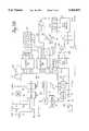
- FIG. 5BA schematic illustration of the preferred electronics located in the housing 14, which combines with the plug electronics 44 to provide a continuous temperature readout on display 16 in response to a signal from the thermopile, is presented in FIG. 5B.
- the systemis based on a microprocessor 75 which processes software routines included in read only memory within the processor chip.
- the processormay be a 6805 processor sold by Motorola.
- the analog output voltage E pc from the amplifier 74is applied as one input to a multiplexer 76.
- Another input to the multiplexer 76is a voltage which is controlled by R a from the thermistor 63.
- the thermistoris coupled in a voltage divider circuit with R3 across a reference potential VREF, and the voltage across R a corresponds to T r .
- a third input to the multiplexer 76is a voltage taken from a voltage divider R1, R2 which is indicative of the potential V+ from the battery (power supply).
- the final input to the multiplexeris a potential taken from a potentiometer R4 which may be adjusted by a user.
- the systemmay be programmed to respond to that input in any of a number of ways. In particular, the potentiometer may be used as a gain control or as a DC offset control.
- one of the four inputsmay be selected by the select lines 78.
- the selected analog signalis applied to a multiple slope analog subsystem 80 used by the microprocessor in an integrating analog-to-digital conversion 80.
- the subsystem 80may be a TSC500A sold by Teledyne. It utilizes the reference voltage VRef from a reference source 82.
- the microprocessor 75responds to the output from the converter 80 to generate a count indicative of the analog input to the converter.
- the microprocessordrives four 7-segment LED displays 82 in a multiplexed fashion. Individual displays are selected sequentially through a column driver 84, and within each selected display the seven segments are controlled through segment drivers 86.
- the switch 22 on the housingWhen the switch 22 on the housing is pressed, it closes the circuit from the battery through resistors R5 and R6 and diode D1 to ground. The capacitor C1 is quickly charged, and field effect transistor T1 is turned on. Through transistor T1, the V+ potential from the battery is applied to a voltage regulator 88.
- the regulator 88provides the regulated +5 volts to the system. It also provides a reset signal to the microprocessor. The reset signal is low until the +5 volt reference is available and thus holds the microprocessor 75 in a reset state. When the +5 volts is available, the reset signal goes high, and the microprocessor begins its programmed routine.
- the switch 22When the switch 22 is released, it opens its circuit, but a charge is maintained on capacitor C1 to keep transistor T1 on. Thus, the system continues to operate. However, the capacitor C1 and transistor T1 provide a very simple watchdog circuit. Periodically, the microprocessor applies a signal through driver 84 to the capacitor C1 to recharge the capacitor and thus keep the transistor T1 on. If the microprocessor should fail to continue its programmed routine, it fails to charge the capacitor C1 within a predetermined time during which the charge on C1 leaks to a level at which transistor T1 turns off. Thus, the microprocessor must continue in its programmed routine or the system shuts down. This prevents spurious readings when the processor is not operating properly.
- the switch 22can be used as an input through diode D2 to the microprocessor to initiate any programmed action of the processor.
- the systemhas a sound output 90 which is driven through the driver 84 by the microprocessor.
- a resistor network 91is used to provide a resistance output corresponding to a standard thermistor value based on the measured temperature.
- a multiplexer 93is used to control the resistor network output. When selected by line 94, the multiplexer receives serial data from line 96 and switches resistor paths in the network to provide a resistance corresponding to a standard thermistor value of the measured temperature.
- a digital-to-analog converter 92is provided. When selected by line 94, the converter converts serial data on line 96 to an analog output on line 98 corresponding to the tympanic temperature. This analog voltage is buffered by an analog buffer 87, and the buffer output Vtemp is made available to a user.
- the housing electronicscomprises circuitry for providing the rate of change of ear canal or tympanic temperature.
- the rate of change of a subject's temperatureis quite helpful. For example, patients often have itic reactions to anesthesia which leads to a runaway metabolism condition causing the patient's temperature to increase rapidly. In these situations, the rate of change of tympanic temperature is a powerful early indication of the condition for a physician.
- a summing junction 160sums the analog output voltage E pc from the preamplifier 74 and the analog voltage controlled by R a .
- the analog output from the summing junction 160is converted to a differential signal over time by a differential capacitor 95 and input to a variable gain amplifier 97.
- the amplifierscales the differential signal to an analog voltage corresponding to the rate of change of target temperature.
- variable gain amplifier 97 output signalis converted to a average rate of change based on the two user selectable time constants s 1 and s 2 which are determined by R111, C111 and R112, C112.
- the userselects the time period over which the rate of change of tympanic temperature is averaged by a depressing a switch 162.
- the position of the switchdetermines which time constant is employed.
- the output signal from the switch 162is sent to an analog buffer 89 and the buffer output Vrate is made available to a user.
- An LED displayis also provided to display the rate of change of tympanic temperature. To that end, the signal on line 99 is sent to an analog-to-digital (A/D) converter 101.
- A/Danalog-to-digital
- a variable resistor R10which is coupled to Vref, serves as a reference for the A/D converter 101.
- the A/D converterhas a built-in 31/2 digit LED display driver which drives the 31/2 digit LED display 103.
- the LED displayhas three 7-segment LED displays and one 2-segment display. The individual segments within each display are controlled by the display driver.
- Both calibration and characterization data required for processing by the microprocessormay be stored in an electrically erasable programmable read only memory (EEPROM) 100.
- the EEPROMmay, for example, be a 93c46 sold by International CMOS Technologies, Inc.
- the datamay be stored in the EEPROM by the microprocessor when the EEPROM is selected by line 102. Once stored in the EEPROM, the data is retained even after power down. Thus, though electrically programmable, once programmed the EEPROM serves as a virtually nonvolatile memory.
- the EEPROMmay be programmed through the microprocessor to store calibration data for calibrating the thermistor and thermopile. Further, characterization data which defines the personality of the infrared detector may be stored. For example, the same electronics hardware, including the microprocessor 75 and its internal program, may be used for a tympanic temperature detector in which the output is accurate in the target temperature range of about 60° F. to a 110° F. or it may be used as an industrial detector in which the target temperature range would be from about 0° F. to 100° F. Further, different modes of operation may be programmed into the system. For example, several different uses of the sound source 90 are available.
- EEPROMis readily programmed by means of an optical communication link which includes a transistor T2 associated with the display.
- a communication boot 104may be placed over the end of the housing during a calibration/characterization procedure.
- a photodiode in the bootgenerates a digitally encoded optical signal which is filtered and applied to the detector T2 to provide an input to the microprocessor 75.
- the microprocessormay communicate optically to a detector in the boot by flashing specific segments of the digital display 82.
- an outside computer 106can monitor the outputs from the thermistor and thermopile and perform a calibration of the devices.
- a unit to be calibratedis pointed at each of two black body radiation sources while the microprocessor 75 converts the signals and sends the values to the external computer.
- the computeris provided with the actual black body temperatures and ambient temperature in the controlled environment of the detector, computes calibration variables and returns those variable to be stored in the detector EEPROM. Similarly, data which characterizes a particular radiation detector may be communicated to the microprocessor for storage in the EEPROM.
- a switch 113may be provided either internally or through the housing to the user to set a mode of operation of the detector. By positioning the switch at either the lock position, the scan position or a neutral position, any of three modes may be selected.
- the first modeis the normal scan mode where the display is updated continuously.
- a second modeis a lock mode where the display locks after a selectable delay and then remains frozen until power is cycled or, optionally, the power-on button is pushed.
- the sound sourcemay be caused to sound at the time of lock.
- the third modeis the peak mode where the display reads the maximum value found since power-on until power is cycled or, optionally, the power-on button is pushed.
- the processordetermines when the voltage from the divider R1, R2 drops below each of two thresholds. Below the higher threshold, the processor periodically enables the sound source to indicate that the battery is low and should be replaced but allows continued readout from the display. Below the lower threshold, the processor determines that any output would be unreliable and no longer displays temperature readings. The unit would then shut down upon release of the power button.
- Power-on buttonresets lock cycle
- Power-on buttonresets peak detect Display degrees C/degrees F EEPROM "Calibrated" pattern to indicate that the device has been calibrated EEPROM checksum for a self-check by the processor
- FIGS. 9A-9Cprovide a flowchart of the firmware stored in the microprocessor 75. From reset when the instrument is turned on, the system is initialized at 110 and the contents of the EEPROM are read into memory in the microprocessor at 112. At 114, the processor reads the state of power and mode switches in the system. At 116, the system determines whether a mode switch 113 has placed the system in a self-test mode. If not, all eights are displayed on the four-digit display 82 for a brief time. At 120, the system performs all A-to-D conversions to obtain digital representations of the thermopile output and the potentiometer settings through multiplexor 76.
- the systemthen enters a loop in which outputs dictated by the mode switch are maintained. First the timers are updated at 122 and the switches are again read at 124. When the power is switched off, from 126 the system enters a power down loop at 128 until the system is fully down. At 130, the mode switch is checked and if changed the system is reset. Although not in the tympanic temperature detector, some detectors have a mode switch available to the user so that the mode of operation can be changed within a loop.
- the systemdetermines its mode of operation and enters the appropriate scan process 134, lock process 138 or peak process 142.
- a scan processthe system updates the output to the current reading in each loop.
- a lock processthe system updates the output but locks onto an output after some period of time.
- the peak processthe system output is the highest indication noted during a scan.
- the systemmay respond to the programming from the EEPROM to perform any number of functions as discussed above.
- the peak processwhich is selected for the tympanic temperature measurement, the system locks onto a peak measurement after a preset period of time.
- the systemmay be set at a test mode 144 which will be described with respect to FIG. 9C. In any of the above-mentioned modes, an output is calculated at 146. Then the system loops back to step 122.
- Analog-to-Digital conversionis performed periodically during an interrupt to the loop of FIG. 9A which occurs every two milliseconds.
- the interrupt routineis illustrated in FIG. 9B.
- Timer countersare updated at 170.
- A-to-D conversionsare made from 172 only every 100 milliseconds when a flag has been set in the prior interrupt cycle. During most interrupts, an A/D conversion does not occur.
- the 100-millisecond counteris checked at 174, and if the count has expired, a flag is set at 176 for the next interrupt. The flag is checked at 178 and, if found, the display is updated at 180. The system then returns to the main loop of FIG. 9A.
- thermopile sensor conversionis performed nine out of ten cycles through the conversion loop.
- the systemchecks to determine whether a conversion is made from the potentiometer R4 or from the battery voltage divider R1, R2 at 192. These conversions are made alternately.
- FIG. 9Cillustrates the self-test sequence which is called by the mode switch 113 only during assembly.
- the beeper sounds at 182 and all display segmentsare displayed at 184.
- the systemsteps each character of the display from zero through nine at 186.
- the systemthen enters a test loop.
- the systemsenses whether the button 108 has been pressed. If so, a display counter is incremented at 190.
- the display for the unitthen depends on the count of the display counter. With the zero count, the adjustment potentiometer value is displayed at 192.
- the display counteris incremented by pressing the button 108, the raw sensor data is displayed. With the next increment, ambient temperature is displayed at 196, and with the next increment, the raw output from the ambient temperature sensor RT1 is displayed. With the next increment, the battery voltage is displayed.
- the assemblersets the mode switch to the proper operating mode.
- FIG. 7AAn alternative embodiment of the tympanic temperature electronics is shown in FIG. 7A.
- a microprocessoris not used and the thermistor of the preferred embodiment is replaced with an absolute temperature device 202.
- a battery 220supplies power to the electronics.
- a regulator unit 222 and a power processor unit 226receive power from the battery.
- the regulatorconverts battery power into voltages V+ and V- which are used by the system electronics.
- the power processor unit 226generates a reference voltage Vref and a low battery voltage indication LO BATT.
- the absolute temperature device 202 of this embodimentis a commercial device designated AD 592 which provides an output current corresponding to sensed ambient temperature in the plug structure. However, any linear device which monitors ambient temperature is acceptable.
- the AD 592produces an output current I a corresponding to the temperature of the mass 40 located in the plug structure.
- the output current I adrives a resistor R33 in the housing electronics producing a voltage output E a which is input to a summing junction 208.
- the sensor output voltage E pc from the amplifier 74is an input to a summing junction 204 located in the housing electronics.
- An adjustable offset voltage produced by a variable resistor R34 coupled to V+ and V-is a second input to the summing junction 204.
- the output voltage of the summing junctionis E pc plus an offset voltage.
- This voltageis an input to a variable gain amplifier 206.
- This amplifierhas an inherent offset which is cancelled by the offset voltage from R34.
- the amplifier outputis simply an amplified E pc .
- a correction factoris required to convert to degrees Celsuis.
- a variable resistor R35is coupled to V+ to generate a correction voltage which is the third input to the summing junction 208.
- the three input voltagesare combined by the summing junction which generates an output voltage on line 209 which corresponds to the tympanic temperature.
- a variable gain amplifier 210converts the voltage on line 209 to an analog voltage on line 212 which is compatible as an A/D converter input.
- the analog voltage on line 212is input to an A/D converter 214.
- a variable resistor R36is coupled to Vref and serves as a reference for the A/D converter 214.
- a 31/2 digit LED display driveris built into the A/D converter and drives the LED display 216.
- the displayhas four 7-segment LED displays for displaying tympanic temperature.
- the display drivercontrols all seven segments in three displays and two segments in the fourth display. All seven segments in the displays are also connected to the LO BATT indication.
- the power processorWhen the system battery 220 is low, the power processor generates a LO BATT voltage which lights all seven segments of the displays to inform a user that a new battery is required.
- the analog voltage on line 212is connected to the analog buffer 87.
- the buffer output Vtempis made available to a user.
- the analog voltage on line 212is manipulated to provide an analog voltage on line 99 which corresponds to the rate of change of tympanic temperature Vrate. As explained earlier, the analog voltage on line 99 is buffered an the buffer output is made available to a user. Additionally, the analog voltage on line 99 is converted to a digital signal which is displayed on the LED display 103.
- FIG. 7BAn alternative configuration of the display circuitry of the above-described embodiment is shown in FIG. 7B.
- the analog voltage on line 212 corresponding to the tympanic temperatureis an input to a multiplexer 234. Concurrently, the analog voltage on line 212 is converted to the rate of change of tympanic temperature which is also an input to the multiplexer.
- the multiplexer outputmay be controlled by a microprocessor (not shown) or a switching circuit (not shown). In either case, the multiplexer output may correspond to the voltage representing the tympanic temperature or the voltage representing the rate of change of the tympanic temperature.
- the A/D converter 236converts the multiplexer output to a digital signal. This signal is an input to a decoder 238 which provides digital signals to a pair of LED display drivers 240 and 242.
- the LED display driversare connected to a pair of four-digit LED displays 248 and 249 which indicate the tympanic temperature and the rate of change of tympanic temperature respectively.
- the individual units of a four-digit displayare selected sequentially by the column driver 242. Within each individual unit, the seven segments are controlled by the segment driver 240.
- the select circuit 246ensures that only one display is enabled to accept signals from the drivers at a time.
- An output on line 245 from the multiplexerindicates which of the displays is to receive signals from the drivers. Thus, if the signal on line 245 enables the lower display 250 to accept signals from the drivers, the select circuit generates a signal which disables the upper display 248.
Landscapes
- Physics & Mathematics (AREA)
- General Physics & Mathematics (AREA)
- Spectroscopy & Molecular Physics (AREA)
- Measuring And Recording Apparatus For Diagnosis (AREA)
Abstract
Description
E.sub.p =C.sub.p (T.sub.1 -T.sub.2) (1)
E.sub.p =C.sub.x (T.sub.t -T.sub.2). (2)
E.sub.c =C.sub.c (T.sub.2 -T.sub.r) (3)
E.sub.pc =E.sub.p +E.sub.c =C.sub.x (T.sub.t -T.sub.2)+C.sub.c (T.sub.2 -T.sub.r). (4)
(K)C.sub.c =C.sub.x.
E.sub.pc =C.sub.x (T.sub.t -T.sub.r). (5)
Claims (15)
Priority Applications (2)
| Application Number | Priority Date | Filing Date | Title |
|---|---|---|---|
| US08/281,766US5469855A (en) | 1991-03-08 | 1994-07-28 | Continuous temperature monitor |
| US08/524,853US5653239A (en) | 1991-03-08 | 1995-09-07 | Continuous temperature monitor |
Applications Claiming Priority (3)
| Application Number | Priority Date | Filing Date | Title |
|---|---|---|---|
| US66674491A | 1991-03-08 | 1991-03-08 | |
| US6048693A | 1993-05-11 | 1993-05-11 | |
| US08/281,766US5469855A (en) | 1991-03-08 | 1994-07-28 | Continuous temperature monitor |
Related Parent Applications (1)
| Application Number | Title | Priority Date | Filing Date |
|---|---|---|---|
| US6048693AContinuation | 1991-03-08 | 1993-05-11 |
Related Child Applications (1)
| Application Number | Title | Priority Date | Filing Date |
|---|---|---|---|
| US08/524,853DivisionUS5653239A (en) | 1991-03-08 | 1995-09-07 | Continuous temperature monitor |
Publications (1)
| Publication Number | Publication Date |
|---|---|
| US5469855Atrue US5469855A (en) | 1995-11-28 |
Family
ID=26739982
Family Applications (2)
| Application Number | Title | Priority Date | Filing Date |
|---|---|---|---|
| US08/281,766Expired - LifetimeUS5469855A (en) | 1991-03-08 | 1994-07-28 | Continuous temperature monitor |
| US08/524,853Expired - LifetimeUS5653239A (en) | 1991-03-08 | 1995-09-07 | Continuous temperature monitor |
Family Applications After (1)
| Application Number | Title | Priority Date | Filing Date |
|---|---|---|---|
| US08/524,853Expired - LifetimeUS5653239A (en) | 1991-03-08 | 1995-09-07 | Continuous temperature monitor |
Country Status (1)
| Country | Link |
|---|---|
| US (2) | US5469855A (en) |
Cited By (76)
| Publication number | Priority date | Publication date | Assignee | Title |
|---|---|---|---|---|
| US5673692A (en)* | 1995-02-03 | 1997-10-07 | Biosignals Ltd. Co. | Single site, multi-variable patient monitor |
| US5823966A (en)* | 1997-05-20 | 1998-10-20 | Buchert; Janusz Michal | Non-invasive continuous blood glucose monitoring |
| US5833367A (en) | 1996-11-12 | 1998-11-10 | Trutek, Inc. | Tympanic thermometer probe cover |
| US5895371A (en)* | 1996-08-27 | 1999-04-20 | Sabratek Corporation | Medical treatment apparatus and method |
| US5967992A (en) | 1998-06-03 | 1999-10-19 | Trutex, Inc. | Radiometric temperature measurement based on empirical measurements and linear functions |
| US6001066A (en) | 1997-06-03 | 1999-12-14 | Trutek, Inc. | Tympanic thermometer with modular sensing probe |
| US6030117A (en) | 1996-11-12 | 2000-02-29 | Trutek, Inc. | Tympanic thermometer probe cover |
| WO2000016049A1 (en)* | 1998-09-16 | 2000-03-23 | Braun Gmbh | Radiation thermometer with a flexible measuring tip |
| WO2000016048A1 (en)* | 1998-09-16 | 2000-03-23 | Braun Gmbh | Radiation thermometer with a rounded measuring tip and a protective cap |
| US6123454A (en) | 1999-06-11 | 2000-09-26 | Trutek, Inc. | Tympanic thermometer disposable probe cover with further stretching prevention structure |
| US6231560B1 (en) | 1999-02-10 | 2001-05-15 | Baxter International Inc | Method and apparatus for automatically controlling the level of medication |
| US6398727B1 (en) | 1998-12-23 | 2002-06-04 | Baxter International Inc. | Method and apparatus for providing patient care |
| US6435711B1 (en) | 1998-09-15 | 2002-08-20 | Jonathan Gerlitz | Infrared ear thermometer |
| US6499877B2 (en)* | 1997-06-24 | 2002-12-31 | Exergen Corporation | Ambient and perfusion normalized temperature detector |
| US6511437B1 (en)* | 1999-11-15 | 2003-01-28 | Yoshinobu Nakamura | Head blood flow balance inspecting apparatus |
| US6547745B1 (en) | 1999-06-23 | 2003-04-15 | Eliahu Rubinstein | Fever alarm system |
| US20030109816A1 (en)* | 2001-12-08 | 2003-06-12 | Charles A. Lachenbruch | Warmable bandage for promoting bandage for promoting wound healing |
| US6584426B2 (en)* | 1998-10-28 | 2003-06-24 | Omron Corporation | Electronic thermometer |
| US6609823B2 (en)* | 2000-05-23 | 2003-08-26 | Braun Gmbh | Infrared radiation thermometer with variable exterior probe head for conforming to body cavity |
| US6631287B2 (en) | 2001-04-03 | 2003-10-07 | Welch Allyn, Inc. | Infrared thermometer |
| US6632400B1 (en) | 2000-06-22 | 2003-10-14 | Agilent Technologies, Inc. | Integrated microfluidic and electronic components |
| US6634787B1 (en)* | 1996-02-06 | 2003-10-21 | Braun Gmbh | Protective cap |
| US6689091B2 (en) | 1996-08-02 | 2004-02-10 | Tuan Bui | Medical apparatus with remote control |
| US20040122338A1 (en)* | 1988-12-06 | 2004-06-24 | Exergen Corporation | Radiation detector probe |
| US20040141884A1 (en)* | 1999-08-19 | 2004-07-22 | Caliper Technologies Corp. | Indicator components for microfluidic systems |
| US20040152991A1 (en)* | 1998-09-11 | 2004-08-05 | Exergen Corporation | Temporal artery temperature detector |
| US6821787B2 (en) | 2000-11-17 | 2004-11-23 | Thermogenic Imaging, Inc. | Apparatus and methods for infrared calorimetric measurements |
| US20040240516A1 (en)* | 2002-12-12 | 2004-12-02 | James Harr | Thermal tympanic thermometer tip |
| US20040254497A1 (en)* | 2000-09-15 | 2004-12-16 | Jacob Fraden | Ear temperature monitor and method of temperature measurement |
| US6835574B2 (en) | 2000-11-17 | 2004-12-28 | Flir Systems Boston, Inc. | Apparatus and methods for infrared calorimetric measurements |
| US20050049471A1 (en)* | 2003-08-25 | 2005-03-03 | Aceti John Gregory | Pulse oximetry methods and apparatus for use within an auditory canal |
| US20050059870A1 (en)* | 2003-08-25 | 2005-03-17 | Aceti John Gregory | Processing methods and apparatus for monitoring physiological parameters using physiological characteristics present within an auditory canal |
| US7001358B2 (en) | 1996-10-24 | 2006-02-21 | Medtronic Vascular, Inc. | Reinforced monorail balloon catheter |
| WO2006091106A1 (en)* | 2005-02-22 | 2006-08-31 | Sinvent As | Clinical ear thermometer |
| US20080200969A1 (en)* | 2007-02-16 | 2008-08-21 | Thermage, Inc. | Temperature sensing apparatus and methods for treatment devices used to deliver high frequency energy to tissue |
| US7434991B2 (en) | 2002-12-12 | 2008-10-14 | Covidien Ag | Thermal tympanic thermometer |
| US20100027582A1 (en)* | 2008-07-29 | 2010-02-04 | Welch Allyn. Inc. | Cycle counting |
| US20100168605A1 (en)* | 2005-08-08 | 2010-07-01 | Koninklijke Philips Electronics, N.V. | Method and apparatus for medical measurement and communication |
| US7785266B2 (en) | 2003-08-19 | 2010-08-31 | Advanced Monitors Corporation | Medical thermometer for determining body core temperature |
| US7828743B2 (en) | 2003-08-19 | 2010-11-09 | Advanced Monitors Corporation | Medical body core thermometer |
| US20100298722A1 (en)* | 2003-10-09 | 2010-11-25 | Nippon Telegraph And Telephone Corp. | Living body information detection apparatus and blood-pressure meter |
| US20110194585A1 (en)* | 2010-02-09 | 2011-08-11 | Abhishek Shrivastava | Multiple object non-contact thermometer |
| US20110228810A1 (en)* | 2010-02-09 | 2011-09-22 | O'hara Gary | Multiple object talking non-contact thermometer |
| EP2437039A2 (en) | 2010-09-30 | 2012-04-04 | Medisim Ltd. | Ergonomic hand held thermometer |
| US8234128B2 (en) | 2002-04-30 | 2012-07-31 | Baxter International, Inc. | System and method for verifying medical device operational parameters |
| US8545435B2 (en) | 2002-01-03 | 2013-10-01 | Baxter International, Inc. | Method and apparatus for providing medical treatment therapy based on calculated demand |
| US20140051948A1 (en)* | 2006-12-19 | 2014-02-20 | Valencell, Inc. | Apparatus for physiological and environmental monitoring with optical and footstep sensors |
| US8775196B2 (en) | 2002-01-29 | 2014-07-08 | Baxter International Inc. | System and method for notification and escalation of medical data |
| CN104523243A (en)* | 2014-12-23 | 2015-04-22 | 金陵科技学院 | Body temperature acquisition device |
| US20160004688A1 (en)* | 2001-12-13 | 2016-01-07 | Peter V. Boesen | Voice communication device with foreign language translation |
| US9307912B2 (en) | 2012-08-08 | 2016-04-12 | Welch Allyn, Inc. | Temperature measurement system |
| WO2016204048A1 (en)* | 2015-06-16 | 2016-12-22 | 株式会社バイオエコーネット | Thermometer |
| US9872812B2 (en) | 2012-09-28 | 2018-01-23 | Kpr U.S., Llc | Residual pressure control in a compression device |
| US10016554B2 (en) | 2008-07-09 | 2018-07-10 | Baxter International Inc. | Dialysis system including wireless patient data |
| US10061899B2 (en) | 2008-07-09 | 2018-08-28 | Baxter International Inc. | Home therapy machine |
| US10173008B2 (en) | 2002-01-29 | 2019-01-08 | Baxter International Inc. | System and method for communicating with a dialysis machine through a network |
| US10347374B2 (en) | 2008-10-13 | 2019-07-09 | Baxter Corporation Englewood | Medication preparation system |
| US10552577B2 (en) | 2012-08-31 | 2020-02-04 | Baxter Corporation Englewood | Medication requisition fulfillment system and method |
| US10646405B2 (en) | 2012-10-26 | 2020-05-12 | Baxter Corporation Englewood | Work station for medical dose preparation system |
| WO2020145179A1 (en)* | 2019-01-10 | 2020-07-16 | 株式会社バイオエコーネット | Holder and ear thermometer using said holder |
| US10818387B2 (en) | 2014-12-05 | 2020-10-27 | Baxter Corporation Englewood | Dose preparation data analytics |
| JP2021048920A (en)* | 2019-09-20 | 2021-04-01 | カシオ計算機株式会社 | Ear type clinical thermometer |
| US10971257B2 (en) | 2012-10-26 | 2021-04-06 | Baxter Corporation Englewood | Image acquisition for medical dose preparation system |
| USD921500S1 (en)* | 2019-10-18 | 2021-06-08 | Shenzhen Nearbyexpress Technology Development Company Limited | Fever monitor |
| US11107574B2 (en) | 2014-09-30 | 2021-08-31 | Baxter Corporation Englewood | Management of medication preparation with formulary management |
| US11298013B2 (en)* | 2014-12-31 | 2022-04-12 | Tyto Care Ltd. | Apparatus and methods for performing body imaging |
| US11367533B2 (en) | 2014-06-30 | 2022-06-21 | Baxter Corporation Englewood | Managed medical information exchange |
| US11495334B2 (en) | 2015-06-25 | 2022-11-08 | Gambro Lundia Ab | Medical device system and method having a distributed database |
| US11516183B2 (en) | 2016-12-21 | 2022-11-29 | Gambro Lundia Ab | Medical device system including information technology infrastructure having secure cluster domain supporting external domain |
| US11575673B2 (en) | 2014-09-30 | 2023-02-07 | Baxter Corporation Englewood | Central user management in a distributed healthcare information management system |
| US20230314239A1 (en)* | 2022-03-31 | 2023-10-05 | Rosemount Inc. | Process fluid temperature estimation using improved heat flow sensor |
| US11948112B2 (en) | 2015-03-03 | 2024-04-02 | Baxter Corporation Engelwood | Pharmacy workflow management with integrated alerts |
| US12101606B2 (en) | 2021-05-28 | 2024-09-24 | Starkey Laboratories, Inc. | Methods and systems for assessing insertion position of hearing instrument |
| US12342131B2 (en) | 2020-09-28 | 2025-06-24 | Starkey Laboratories, Inc. | Temperature sensor based ear-worn electronic device fit assessment |
| US12389166B2 (en) | 2020-07-31 | 2025-08-12 | Starkey Laboratories, Inc. | Sensor based ear-worn electronic device fit assessment |
| US12412644B2 (en) | 2014-10-24 | 2025-09-09 | Baxter Corporation Englewood | Automated exchange of healthcare information for fulfillment of medication doses |
Families Citing this family (190)
| Publication number | Priority date | Publication date | Assignee | Title |
|---|---|---|---|---|
| US5984875A (en)* | 1997-08-22 | 1999-11-16 | Innotek Pet Products, Inc. | Ingestible animal temperature sensor |
| US6283628B1 (en)* | 1998-09-11 | 2001-09-04 | Airpax Corporation, Llc | Intelligent input/output temperature sensor and calibration method therefor |
| US6367972B1 (en)* | 1998-09-29 | 2002-04-09 | Ishizuka Electronics Corporation | Non-contact temperature sensor with temperature compensating heat sensitive elements on plastic film |
| US6258043B1 (en)* | 1999-01-05 | 2001-07-10 | Gabriel Raviv | Ear probe tip |
| DE29902276U1 (en)* | 1999-02-09 | 1999-04-15 | Chen, Chao-Wang, Taipeh/T'ai-pei | Infrared sensor for a thermometer |
| CA2365863A1 (en)* | 1999-03-04 | 2000-09-08 | Ddx, Inc. | Electronic body temperature monitoring device |
| DE19942089C1 (en)* | 1999-09-03 | 2001-06-13 | Geratherm Medical Ag | Medical thermometer |
| US6450970B1 (en) | 1999-11-16 | 2002-09-17 | Ron Mahler | Method and device for diagnosing an inflammatory process |
| US6270463B1 (en)* | 1999-11-23 | 2001-08-07 | Medrad, Inc. | System and method for measuring temperature in a strong electromagnetic field |
| US6319206B1 (en)* | 1999-11-24 | 2001-11-20 | Exergen Corporation | Temporal thermometer disposable cap |
| US6527796B1 (en)* | 2000-01-24 | 2003-03-04 | James A. Magovern | Method and apparatus for burning calories |
| US6688119B2 (en)* | 2000-12-22 | 2004-02-10 | General Electric Company | Methods and apparatus for increasing appliance measuring system accuracy |
| EP1351601A2 (en)* | 2001-01-03 | 2003-10-15 | Microlife Intellectual Property GmbH | A system for measuring at least one body parameter, a blood pressure monitor and a medical thermometer |
| WO2002065960A1 (en)* | 2001-02-16 | 2002-08-29 | Cardiac Assist Technologies, Inc. | Method and apparatus for burning calories |
| US6637931B2 (en)* | 2001-07-19 | 2003-10-28 | Oriental System Technology Inc. | Probe for use in an infrared thermometer |
| ES2327510T3 (en)* | 2002-02-25 | 2009-10-30 | Scott Laboratories, Inc. | PROTECTION MODULE AGAINST FAILURES, INTEGRATED WITH AN ANALGESY AND SEDATION SYSTEM. |
| US9848815B2 (en) | 2002-04-22 | 2017-12-26 | Geelux Holdings, Ltd. | Apparatus and method for measuring biologic parameters |
| US8328420B2 (en) | 2003-04-22 | 2012-12-11 | Marcio Marc Abreu | Apparatus and method for measuring biologic parameters |
| JP4347216B2 (en) | 2002-04-22 | 2009-10-21 | マルシオ マルク アブリュー | Biological parameter measuring device |
| US7052471B2 (en)* | 2002-05-08 | 2006-05-30 | Medport Llc | Digital thermometer for measuring body temperature |
| US20030216624A1 (en)* | 2002-05-16 | 2003-11-20 | Microlife Intellectual Property Gmbh | System for monitoring medical data, a terminal device for measuring and storing medical data, a medicine container and a holder for medical containers |
| US7140768B2 (en)* | 2002-07-15 | 2006-11-28 | Cold Chain Technologies, Inc. | System and method of monitoring temperature |
| US7381184B2 (en) | 2002-11-05 | 2008-06-03 | Abbott Diabetes Care Inc. | Sensor inserter assembly |
| US7811231B2 (en) | 2002-12-31 | 2010-10-12 | Abbott Diabetes Care Inc. | Continuous glucose monitoring system and methods of use |
| WO2004074794A1 (en)* | 2003-02-20 | 2004-09-02 | Ysi Incorporated | Digitally modified resistive output for a temperature sensor |
| US8066639B2 (en) | 2003-06-10 | 2011-11-29 | Abbott Diabetes Care Inc. | Glucose measuring device for use in personal area network |
| US20190357827A1 (en) | 2003-08-01 | 2019-11-28 | Dexcom, Inc. | Analyte sensor |
| KR100763233B1 (en)* | 2003-08-11 | 2007-10-04 | 삼성전자주식회사 | Apparatus and method for detecting bleeding blood flow signal and stress testing apparatus using same |
| US7920906B2 (en) | 2005-03-10 | 2011-04-05 | Dexcom, Inc. | System and methods for processing analyte sensor data for sensor calibration |
| US7299082B2 (en) | 2003-10-31 | 2007-11-20 | Abbott Diabetes Care, Inc. | Method of calibrating an analyte-measurement device, and associated methods, devices and systems |
| USD902408S1 (en) | 2003-11-05 | 2020-11-17 | Abbott Diabetes Care Inc. | Analyte sensor control unit |
| WO2005089103A2 (en) | 2004-02-17 | 2005-09-29 | Therasense, Inc. | Method and system for providing data communication in continuous glucose monitoring and management system |
| US10227063B2 (en) | 2004-02-26 | 2019-03-12 | Geelux Holdings, Ltd. | Method and apparatus for biological evaluation |
| EP1810185A4 (en) | 2004-06-04 | 2010-01-06 | Therasense Inc | Diabetes care host-client architecture and data management system |
| US7654956B2 (en) | 2004-07-13 | 2010-02-02 | Dexcom, Inc. | Transcutaneous analyte sensor |
| US8571624B2 (en) | 2004-12-29 | 2013-10-29 | Abbott Diabetes Care Inc. | Method and apparatus for mounting a data transmission device in a communication system |
| US9743862B2 (en) | 2011-03-31 | 2017-08-29 | Abbott Diabetes Care Inc. | Systems and methods for transcutaneously implanting medical devices |
| US8512243B2 (en) | 2005-09-30 | 2013-08-20 | Abbott Diabetes Care Inc. | Integrated introducer and transmitter assembly and methods of use |
| US7731657B2 (en) | 2005-08-30 | 2010-06-08 | Abbott Diabetes Care Inc. | Analyte sensor introducer and methods of use |
| US8333714B2 (en) | 2006-09-10 | 2012-12-18 | Abbott Diabetes Care Inc. | Method and system for providing an integrated analyte sensor insertion device and data processing unit |
| US10226207B2 (en) | 2004-12-29 | 2019-03-12 | Abbott Diabetes Care Inc. | Sensor inserter having introducer |
| US20090105569A1 (en) | 2006-04-28 | 2009-04-23 | Abbott Diabetes Care, Inc. | Introducer Assembly and Methods of Use |
| US7883464B2 (en) | 2005-09-30 | 2011-02-08 | Abbott Diabetes Care Inc. | Integrated transmitter unit and sensor introducer mechanism and methods of use |
| US9259175B2 (en) | 2006-10-23 | 2016-02-16 | Abbott Diabetes Care, Inc. | Flexible patch for fluid delivery and monitoring body analytes |
| US7697967B2 (en) | 2005-12-28 | 2010-04-13 | Abbott Diabetes Care Inc. | Method and apparatus for providing analyte sensor insertion |
| US9572534B2 (en) | 2010-06-29 | 2017-02-21 | Abbott Diabetes Care Inc. | Devices, systems and methods for on-skin or on-body mounting of medical devices |
| US8029441B2 (en) | 2006-02-28 | 2011-10-04 | Abbott Diabetes Care Inc. | Analyte sensor transmitter unit configuration for a data monitoring and management system |
| US9636450B2 (en) | 2007-02-19 | 2017-05-02 | Udo Hoss | Pump system modular components for delivering medication and analyte sensing at seperate insertion sites |
| US9788771B2 (en) | 2006-10-23 | 2017-10-17 | Abbott Diabetes Care Inc. | Variable speed sensor insertion devices and methods of use |
| US9398882B2 (en) | 2005-09-30 | 2016-07-26 | Abbott Diabetes Care Inc. | Method and apparatus for providing analyte sensor and data processing device |
| US8112240B2 (en) | 2005-04-29 | 2012-02-07 | Abbott Diabetes Care Inc. | Method and apparatus for providing leak detection in data monitoring and management systems |
| JP2009507224A (en) | 2005-08-31 | 2009-02-19 | ユニヴァーシティー オブ ヴァージニア パテント ファンデーション | Improving the accuracy of continuous glucose sensors |
| US9521968B2 (en) | 2005-09-30 | 2016-12-20 | Abbott Diabetes Care Inc. | Analyte sensor retention mechanism and methods of use |
| US8880138B2 (en) | 2005-09-30 | 2014-11-04 | Abbott Diabetes Care Inc. | Device for channeling fluid and methods of use |
| ES2399872T3 (en) | 2005-10-24 | 2013-04-04 | Marcio Marc Aurelio Martins Abreu | Apparatus for measuring biological parameters |
| US7766829B2 (en) | 2005-11-04 | 2010-08-03 | Abbott Diabetes Care Inc. | Method and system for providing basal profile modification in analyte monitoring and management systems |
| CA2636034A1 (en) | 2005-12-28 | 2007-10-25 | Abbott Diabetes Care Inc. | Medical device insertion |
| US11298058B2 (en) | 2005-12-28 | 2022-04-12 | Abbott Diabetes Care Inc. | Method and apparatus for providing analyte sensor insertion |
| US7736310B2 (en) | 2006-01-30 | 2010-06-15 | Abbott Diabetes Care Inc. | On-body medical device securement |
| US7885698B2 (en) | 2006-02-28 | 2011-02-08 | Abbott Diabetes Care Inc. | Method and system for providing continuous calibration of implantable analyte sensors |
| US7826879B2 (en) | 2006-02-28 | 2010-11-02 | Abbott Diabetes Care Inc. | Analyte sensors and methods of use |
| US9392969B2 (en) | 2008-08-31 | 2016-07-19 | Abbott Diabetes Care Inc. | Closed loop control and signal attenuation detection |
| US8226891B2 (en) | 2006-03-31 | 2012-07-24 | Abbott Diabetes Care Inc. | Analyte monitoring devices and methods therefor |
| US8224415B2 (en) | 2009-01-29 | 2012-07-17 | Abbott Diabetes Care Inc. | Method and device for providing offset model based calibration for analyte sensor |
| US8140312B2 (en) | 2007-05-14 | 2012-03-20 | Abbott Diabetes Care Inc. | Method and system for determining analyte levels |
| US9326709B2 (en) | 2010-03-10 | 2016-05-03 | Abbott Diabetes Care Inc. | Systems, devices and methods for managing glucose levels |
| US8219173B2 (en) | 2008-09-30 | 2012-07-10 | Abbott Diabetes Care Inc. | Optimizing analyte sensor calibration |
| US7653425B2 (en) | 2006-08-09 | 2010-01-26 | Abbott Diabetes Care Inc. | Method and system for providing calibration of an analyte sensor in an analyte monitoring system |
| US8374668B1 (en) | 2007-10-23 | 2013-02-12 | Abbott Diabetes Care Inc. | Analyte sensor with lag compensation |
| US7630748B2 (en) | 2006-10-25 | 2009-12-08 | Abbott Diabetes Care Inc. | Method and system for providing analyte monitoring |
| US8478557B2 (en) | 2009-07-31 | 2013-07-02 | Abbott Diabetes Care Inc. | Method and apparatus for providing analyte monitoring system calibration accuracy |
| US8346335B2 (en) | 2008-03-28 | 2013-01-01 | Abbott Diabetes Care Inc. | Analyte sensor calibration management |
| US7618369B2 (en) | 2006-10-02 | 2009-11-17 | Abbott Diabetes Care Inc. | Method and system for dynamically updating calibration parameters for an analyte sensor |
| US7620438B2 (en) | 2006-03-31 | 2009-11-17 | Abbott Diabetes Care Inc. | Method and system for powering an electronic device |
| US9675290B2 (en) | 2012-10-30 | 2017-06-13 | Abbott Diabetes Care Inc. | Sensitivity calibration of in vivo sensors used to measure analyte concentration |
| US7801582B2 (en) | 2006-03-31 | 2010-09-21 | Abbott Diabetes Care Inc. | Analyte monitoring and management system and methods therefor |
| US8473022B2 (en) | 2008-01-31 | 2013-06-25 | Abbott Diabetes Care Inc. | Analyte sensor with time lag compensation |
| US8583205B2 (en) | 2008-03-28 | 2013-11-12 | Abbott Diabetes Care Inc. | Analyte sensor calibration management |
| WO2007143225A2 (en) | 2006-06-07 | 2007-12-13 | Abbott Diabetes Care, Inc. | Analyte monitoring system and method |
| US8135548B2 (en) | 2006-10-26 | 2012-03-13 | Abbott Diabetes Care Inc. | Method, system and computer program product for real-time detection of sensitivity decline in analyte sensors |
| US20080199894A1 (en) | 2007-02-15 | 2008-08-21 | Abbott Diabetes Care, Inc. | Device and method for automatic data acquisition and/or detection |
| US8121857B2 (en) | 2007-02-15 | 2012-02-21 | Abbott Diabetes Care Inc. | Device and method for automatic data acquisition and/or detection |
| US8930203B2 (en) | 2007-02-18 | 2015-01-06 | Abbott Diabetes Care Inc. | Multi-function analyte test device and methods therefor |
| US8732188B2 (en) | 2007-02-18 | 2014-05-20 | Abbott Diabetes Care Inc. | Method and system for providing contextual based medication dosage determination |
| US8123686B2 (en) | 2007-03-01 | 2012-02-28 | Abbott Diabetes Care Inc. | Method and apparatus for providing rolling data in communication systems |
| CA2683953C (en) | 2007-04-14 | 2016-08-02 | Abbott Diabetes Care Inc. | Method and apparatus for providing data processing and control in medical communication system |
| EP2137637A4 (en) | 2007-04-14 | 2012-06-20 | Abbott Diabetes Care Inc | Method and apparatus for providing data processing and control in medical communication system |
| WO2008130895A2 (en)* | 2007-04-14 | 2008-10-30 | Abbott Diabetes Care, Inc. | Method and apparatus for providing dynamic multi-stage signal amplification in a medical device |
| WO2008130898A1 (en) | 2007-04-14 | 2008-10-30 | Abbott Diabetes Care, Inc. | Method and apparatus for providing data processing and control in medical communication system |
| US10111608B2 (en) | 2007-04-14 | 2018-10-30 | Abbott Diabetes Care Inc. | Method and apparatus for providing data processing and control in medical communication system |
| WO2008130897A2 (en) | 2007-04-14 | 2008-10-30 | Abbott Diabetes Care, Inc. | Method and apparatus for providing data processing and control in medical communication system |
| US7928850B2 (en) | 2007-05-08 | 2011-04-19 | Abbott Diabetes Care Inc. | Analyte monitoring system and methods |
| US8461985B2 (en) | 2007-05-08 | 2013-06-11 | Abbott Diabetes Care Inc. | Analyte monitoring system and methods |
| US8456301B2 (en) | 2007-05-08 | 2013-06-04 | Abbott Diabetes Care Inc. | Analyte monitoring system and methods |
| US8665091B2 (en) | 2007-05-08 | 2014-03-04 | Abbott Diabetes Care Inc. | Method and device for determining elapsed sensor life |
| US8600681B2 (en) | 2007-05-14 | 2013-12-03 | Abbott Diabetes Care Inc. | Method and apparatus for providing data processing and control in a medical communication system |
| US8444560B2 (en) | 2007-05-14 | 2013-05-21 | Abbott Diabetes Care Inc. | Method and apparatus for providing data processing and control in a medical communication system |
| US8560038B2 (en) | 2007-05-14 | 2013-10-15 | Abbott Diabetes Care Inc. | Method and apparatus for providing data processing and control in a medical communication system |
| US8103471B2 (en) | 2007-05-14 | 2012-01-24 | Abbott Diabetes Care Inc. | Method and apparatus for providing data processing and control in a medical communication system |
| US8260558B2 (en) | 2007-05-14 | 2012-09-04 | Abbott Diabetes Care Inc. | Method and apparatus for providing data processing and control in a medical communication system |
| US7996158B2 (en) | 2007-05-14 | 2011-08-09 | Abbott Diabetes Care Inc. | Method and apparatus for providing data processing and control in a medical communication system |
| US9125548B2 (en) | 2007-05-14 | 2015-09-08 | Abbott Diabetes Care Inc. | Method and apparatus for providing data processing and control in a medical communication system |
| US8239166B2 (en) | 2007-05-14 | 2012-08-07 | Abbott Diabetes Care Inc. | Method and apparatus for providing data processing and control in a medical communication system |
| US10002233B2 (en) | 2007-05-14 | 2018-06-19 | Abbott Diabetes Care Inc. | Method and apparatus for providing data processing and control in a medical communication system |
| WO2008150917A1 (en) | 2007-05-31 | 2008-12-11 | Abbott Diabetes Care, Inc. | Insertion devices and methods |
| AU2008265542B2 (en) | 2007-06-21 | 2014-07-24 | Abbott Diabetes Care Inc. | Health monitor |
| WO2008157820A1 (en) | 2007-06-21 | 2008-12-24 | Abbott Diabetes Care, Inc. | Health management devices and methods |
| US8160900B2 (en) | 2007-06-29 | 2012-04-17 | Abbott Diabetes Care Inc. | Analyte monitoring and management device and method to analyze the frequency of user interaction with the device |
| US8834366B2 (en) | 2007-07-31 | 2014-09-16 | Abbott Diabetes Care Inc. | Method and apparatus for providing analyte sensor calibration |
| US7768386B2 (en) | 2007-07-31 | 2010-08-03 | Abbott Diabetes Care Inc. | Method and apparatus for providing data processing and control in a medical communication system |
| US8377031B2 (en) | 2007-10-23 | 2013-02-19 | Abbott Diabetes Care Inc. | Closed loop control system with safety parameters and methods |
| US8409093B2 (en) | 2007-10-23 | 2013-04-02 | Abbott Diabetes Care Inc. | Assessing measures of glycemic variability |
| US8216138B1 (en) | 2007-10-23 | 2012-07-10 | Abbott Diabetes Care Inc. | Correlation of alternative site blood and interstitial fluid glucose concentrations to venous glucose concentration |
| US20090164239A1 (en) | 2007-12-19 | 2009-06-25 | Abbott Diabetes Care, Inc. | Dynamic Display Of Glucose Information |
| EP2982383B1 (en) | 2008-04-10 | 2019-05-15 | Abbott Diabetes Care, Inc. | Method for sterilizing an analyte sensor |
| US8924159B2 (en) | 2008-05-30 | 2014-12-30 | Abbott Diabetes Care Inc. | Method and apparatus for providing glycemic control |
| US7826382B2 (en) | 2008-05-30 | 2010-11-02 | Abbott Diabetes Care Inc. | Close proximity communication device and methods |
| US8591410B2 (en) | 2008-05-30 | 2013-11-26 | Abbott Diabetes Care Inc. | Method and apparatus for providing glycemic control |
| US8876755B2 (en) | 2008-07-14 | 2014-11-04 | Abbott Diabetes Care Inc. | Closed loop control system interface and methods |
| US9943644B2 (en) | 2008-08-31 | 2018-04-17 | Abbott Diabetes Care Inc. | Closed loop control with reference measurement and methods thereof |
| US8622988B2 (en) | 2008-08-31 | 2014-01-07 | Abbott Diabetes Care Inc. | Variable rate closed loop control and methods |
| US8734422B2 (en) | 2008-08-31 | 2014-05-27 | Abbott Diabetes Care Inc. | Closed loop control with improved alarm functions |
| US20100057040A1 (en) | 2008-08-31 | 2010-03-04 | Abbott Diabetes Care, Inc. | Robust Closed Loop Control And Methods |
| US8986208B2 (en) | 2008-09-30 | 2015-03-24 | Abbott Diabetes Care Inc. | Analyte sensor sensitivity attenuation mitigation |
| US9326707B2 (en) | 2008-11-10 | 2016-05-03 | Abbott Diabetes Care Inc. | Alarm characterization for analyte monitoring devices and systems |
| US8103456B2 (en) | 2009-01-29 | 2012-01-24 | Abbott Diabetes Care Inc. | Method and device for early signal attenuation detection using blood glucose measurements |
| US9402544B2 (en) | 2009-02-03 | 2016-08-02 | Abbott Diabetes Care Inc. | Analyte sensor and apparatus for insertion of the sensor |
| US8497777B2 (en) | 2009-04-15 | 2013-07-30 | Abbott Diabetes Care Inc. | Analyte monitoring system having an alert |
| WO2010127050A1 (en) | 2009-04-28 | 2010-11-04 | Abbott Diabetes Care Inc. | Error detection in critical repeating data in a wireless sensor system |
| US8368556B2 (en) | 2009-04-29 | 2013-02-05 | Abbott Diabetes Care Inc. | Method and system for providing data communication in continuous glucose monitoring and management system |
| EP2425209A4 (en) | 2009-04-29 | 2013-01-09 | Abbott Diabetes Care Inc | METHOD AND SYSTEM FOR PROVIDING REAL-TIME ANALYTE SENSOR CALIBRATION WITH RETROSPECTIVE FILLING |
| WO2010135646A1 (en) | 2009-05-22 | 2010-11-25 | Abbott Diabetes Care Inc. | Usability features for integrated insulin delivery system |
| WO2010138856A1 (en) | 2009-05-29 | 2010-12-02 | Abbott Diabetes Care Inc. | Medical device antenna systems having external antenna configurations |
| US8613892B2 (en) | 2009-06-30 | 2013-12-24 | Abbott Diabetes Care Inc. | Analyte meter with a moveable head and methods of using the same |
| DK3689237T3 (en) | 2009-07-23 | 2021-08-16 | Abbott Diabetes Care Inc | Method of preparation and system for continuous analyte measurement |
| LT4147999T (en) | 2009-08-31 | 2024-10-10 | Abbott Diabetes Care, Inc. | MEDICAL DEVICE DISPLAYS |
| EP3001194B1 (en) | 2009-08-31 | 2019-04-17 | Abbott Diabetes Care, Inc. | Medical devices and methods |
| US8993331B2 (en) | 2009-08-31 | 2015-03-31 | Abbott Diabetes Care Inc. | Analyte monitoring system and methods for managing power and noise |
| US9314195B2 (en) | 2009-08-31 | 2016-04-19 | Abbott Diabetes Care Inc. | Analyte signal processing device and methods |
| US9320461B2 (en) | 2009-09-29 | 2016-04-26 | Abbott Diabetes Care Inc. | Method and apparatus for providing notification function in analyte monitoring systems |
| WO2011041531A1 (en) | 2009-09-30 | 2011-04-07 | Abbott Diabetes Care Inc. | Interconnect for on-body analyte monitoring device |
| WO2011053881A1 (en) | 2009-10-30 | 2011-05-05 | Abbott Diabetes Care Inc. | Method and apparatus for detecting false hypoglycemic conditions |
| USD924406S1 (en) | 2010-02-01 | 2021-07-06 | Abbott Diabetes Care Inc. | Analyte sensor inserter |
| LT3622883T (en) | 2010-03-24 | 2021-08-25 | Abbott Diabetes Care, Inc. | Medical device inserters and processes of inserting and using medical devices |
| US8635046B2 (en) | 2010-06-23 | 2014-01-21 | Abbott Diabetes Care Inc. | Method and system for evaluating analyte sensor response characteristics |
| US10092229B2 (en) | 2010-06-29 | 2018-10-09 | Abbott Diabetes Care Inc. | Calibration of analyte measurement system |
| US11064921B2 (en) | 2010-06-29 | 2021-07-20 | Abbott Diabetes Care Inc. | Devices, systems and methods for on-skin or on-body mounting of medical devices |
| US11213226B2 (en) | 2010-10-07 | 2022-01-04 | Abbott Diabetes Care Inc. | Analyte monitoring devices and methods |
| US10136845B2 (en) | 2011-02-28 | 2018-11-27 | Abbott Diabetes Care Inc. | Devices, systems, and methods associated with analyte monitoring devices and devices incorporating the same |
| CN107019515B (en) | 2011-02-28 | 2021-02-26 | 雅培糖尿病护理公司 | Method of displaying sensor readings and analyte monitoring device and method of operating the same |
| EP2697650B1 (en) | 2011-04-15 | 2020-09-30 | Dexcom, Inc. | Advanced analyte sensor calibration and error detection |
| US9974472B2 (en) | 2011-06-16 | 2018-05-22 | Abbott Diabetes Care Inc. | Temperature-compensated analyte monitoring devices, systems, and methods thereof |
| US9622691B2 (en) | 2011-10-31 | 2017-04-18 | Abbott Diabetes Care Inc. | Model based variable risk false glucose threshold alarm prevention mechanism |
| US9069536B2 (en) | 2011-10-31 | 2015-06-30 | Abbott Diabetes Care Inc. | Electronic devices having integrated reset systems and methods thereof |
| WO2013070794A2 (en) | 2011-11-07 | 2013-05-16 | Abbott Diabetes Care Inc. | Analyte monitoring device and methods |
| US9317656B2 (en) | 2011-11-23 | 2016-04-19 | Abbott Diabetes Care Inc. | Compatibility mechanisms for devices in a continuous analyte monitoring system and methods thereof |
| US8710993B2 (en) | 2011-11-23 | 2014-04-29 | Abbott Diabetes Care Inc. | Mitigating single point failure of devices in an analyte monitoring system and methods thereof |
| WO2013078426A2 (en) | 2011-11-25 | 2013-05-30 | Abbott Diabetes Care Inc. | Analyte monitoring system and methods of use |
| EP2713879B1 (en) | 2011-12-11 | 2017-07-26 | Abbott Diabetes Care, Inc. | Analyte sensor devices, connections, and methods |
| US10132793B2 (en) | 2012-08-30 | 2018-11-20 | Abbott Diabetes Care Inc. | Dropout detection in continuous analyte monitoring data during data excursions |
| US9968306B2 (en) | 2012-09-17 | 2018-05-15 | Abbott Diabetes Care Inc. | Methods and apparatuses for providing adverse condition notification with enhanced wireless communication range in analyte monitoring systems |
| WO2014052136A1 (en) | 2012-09-26 | 2014-04-03 | Abbott Diabetes Care Inc. | Method and apparatus for improving lag correction during in vivo measurement of analyte concentration with analyte concentration variability and range data |
| US10076285B2 (en) | 2013-03-15 | 2018-09-18 | Abbott Diabetes Care Inc. | Sensor fault detection using analyte sensor data pattern comparison |
| US9474475B1 (en) | 2013-03-15 | 2016-10-25 | Abbott Diabetes Care Inc. | Multi-rate analyte sensor data collection with sample rate configurable signal processing |
| US10433773B1 (en) | 2013-03-15 | 2019-10-08 | Abbott Diabetes Care Inc. | Noise rejection methods and apparatus for sparsely sampled analyte sensor data |
| US20150105687A1 (en) | 2013-10-11 | 2015-04-16 | Geelux Holding, Ltd. | Method and apparatus for biological evaluation |
| WO2015102745A1 (en) | 2013-12-31 | 2015-07-09 | Abbott Diabetes Care Inc. | Self-powered analyte sensor and devices using the same |
| JP2017501844A (en) | 2014-01-10 | 2017-01-19 | マーシオ マーク アブリュー | Device for measuring the infrared output of an Abreu brain thermal tunnel |
| US10251776B2 (en) | 2014-01-10 | 2019-04-09 | Geelux Holding, Ltd. | Devices configured to monitor biological parameters, and to provide treatment, at an Abreu brain thermal tunnel |
| CN106163463A (en) | 2014-01-22 | 2016-11-23 | 马尔西奥·马克·阿布雷乌 | Device configured to provide treatment in an ABREU brain thermal tunnel |
| US20170185748A1 (en) | 2014-03-30 | 2017-06-29 | Abbott Diabetes Care Inc. | Method and Apparatus for Determining Meal Start and Peak Events in Analyte Monitoring Systems |
| US10271736B2 (en) | 2014-04-15 | 2019-04-30 | Koninklijke Philips N.V. | Low cost magnetic resonance safe probe for temperature measurement |
| CN103961071A (en)* | 2014-05-27 | 2014-08-06 | 江苏潮人信息科技有限公司 | Wearable electronic clinical thermometer |
| US11872018B2 (en) | 2015-03-10 | 2024-01-16 | Brain Tunnelgenix Technologies Corp. | Devices, apparatuses, systems, and methods for measuring temperature of an ABTT terminus |
| WO2016183493A1 (en) | 2015-05-14 | 2016-11-17 | Abbott Diabetes Care Inc. | Compact medical device inserters and related systems and methods |
| US10213139B2 (en) | 2015-05-14 | 2019-02-26 | Abbott Diabetes Care Inc. | Systems, devices, and methods for assembling an applicator and sensor control device |
| DE202016009220U1 (en) | 2015-07-10 | 2024-07-09 | Abbott Diabetes Care, Inc. | Device and system for dynamic glucose profile response to physiological parameters |
| WO2017015661A1 (en)* | 2015-07-23 | 2017-01-26 | Yono Health Inc. | System for body temperature measurement |
| GB2554632B (en)* | 2016-05-24 | 2021-02-24 | Inova Design Solution Ltd | Portable physiology monitor |
| US11071478B2 (en) | 2017-01-23 | 2021-07-27 | Abbott Diabetes Care Inc. | Systems, devices and methods for analyte sensor insertion |
| WO2018175489A1 (en) | 2017-03-21 | 2018-09-27 | Abbott Diabetes Care Inc. | Methods, devices and system for providing diabetic condition diagnosis and therapy |
| US11331022B2 (en) | 2017-10-24 | 2022-05-17 | Dexcom, Inc. | Pre-connected analyte sensors |
| US20190120785A1 (en) | 2017-10-24 | 2019-04-25 | Dexcom, Inc. | Pre-connected analyte sensors |
| USD1002852S1 (en) | 2019-06-06 | 2023-10-24 | Abbott Diabetes Care Inc. | Analyte sensor device |
| US20210108967A1 (en) | 2019-10-14 | 2021-04-15 | Justin Thrash | TempTech |
| US11585557B2 (en) | 2020-07-01 | 2023-02-21 | International Business Machines Corporation | Anomaly detection based on airflow alerters |
| US11512861B2 (en) | 2020-07-01 | 2022-11-29 | International Business Machines Corporation | Anomaly detection based on airflow measurement |
| US11187586B2 (en)* | 2020-08-17 | 2021-11-30 | SoCal Dab Tools, LLC | Temperature sensing system |
| CA3188510A1 (en) | 2020-08-31 | 2022-03-03 | Vivek S. RAO | Systems, devices, and methods for analyte sensor insertion |
| USD999913S1 (en) | 2020-12-21 | 2023-09-26 | Abbott Diabetes Care Inc | Analyte sensor inserter |
Citations (27)
| Publication number | Priority date | Publication date | Assignee | Title |
|---|---|---|---|---|
| US3080011A (en)* | 1956-07-16 | 1963-03-05 | John D Henderson | Ear canal insert |
| US3156117A (en)* | 1961-09-21 | 1964-11-10 | Theodor H Benzinger | Clinical ear thermometer |
| US3282106A (en)* | 1963-01-28 | 1966-11-01 | Barnes Eng Co | Method of measuring body temperature |
| US3491596A (en)* | 1967-10-02 | 1970-01-27 | Vito Charles P De | Temperature sensing device |
| US3581570A (en)* | 1967-09-05 | 1971-06-01 | Garrett Corp | Thermal radiation sensor |
| US3626757A (en)* | 1967-10-24 | 1971-12-14 | Theodor H Benzinger | Ear thermometer |
| US3833115A (en)* | 1972-02-24 | 1974-09-03 | R Schapker | Clinical probe and disposable sheath |
| US3878836A (en)* | 1973-08-23 | 1975-04-22 | Products Int Marketing | Disposable speculum for tympanic thermometer |
| US3949740A (en)* | 1973-08-23 | 1976-04-13 | Products International Marketing | Disposable speculum for tympanic thermometer |
| SU601001A1 (en)* | 1976-06-28 | 1978-04-05 | Предприятие П/Я В-2343 | Device for taking temperature in external auditory meatus |
| US4191197A (en)* | 1978-03-14 | 1980-03-04 | Benzinger Theodor H | Touch free tympanic thermometer |
| US4297685A (en)* | 1979-05-31 | 1981-10-27 | Environmental Devices Corporation | Apparatus and method for sleep detection |
| US4380998A (en)* | 1981-01-05 | 1983-04-26 | Welch Allyn, Inc. | Soft tip speculum |
| US4537187A (en)* | 1983-10-06 | 1985-08-27 | Scott Robert T | Earplug |
| US4567881A (en)* | 1983-03-31 | 1986-02-04 | Welch Allyn Inc. | Combination otoscope and audiometer |
| US4582053A (en)* | 1984-01-06 | 1986-04-15 | Wilson Garnet J E | Acoustic ear plug |
| US4602642A (en)* | 1984-10-23 | 1986-07-29 | Intelligent Medical Systems, Inc. | Method and apparatus for measuring internal body temperature utilizing infrared emissions |
| US4797840A (en)* | 1985-04-17 | 1989-01-10 | Thermoscan Inc. | Infrared electronic thermometer and method for measuring temperature |
| US4865044A (en)* | 1987-03-09 | 1989-09-12 | Wallace Thomas L | Temperature-sensing system for cattle |
| US4878560A (en)* | 1989-03-16 | 1989-11-07 | Scott Robert T | Earmold |
| US4881616A (en)* | 1989-04-07 | 1989-11-21 | Janssen Gwen V | Hearing aid retention apparatus |
| US4895164A (en)* | 1988-09-15 | 1990-01-23 | Telatemp Corp. | Infrared clinical thermometer |
| US4993419A (en)* | 1988-12-06 | 1991-02-19 | Exergen Corporation | Radiation detector suitable for tympanic temperature measurement |
| US5017019A (en)* | 1989-04-14 | 1991-05-21 | Exergen Corporation | Radiation detector for differential biological temperature readings |
| US5046580A (en)* | 1990-08-17 | 1991-09-10 | Barton James I | Ear plug assembly for hearing aid |
| US5088834A (en)* | 1990-08-24 | 1992-02-18 | Thermoscan Inc. | Unitary probe cover |
| US5325863A (en)* | 1988-12-06 | 1994-07-05 | Exergen Corporation | Radiation detector with high thermal stability |
Family Cites Families (2)
| Publication number | Priority date | Publication date | Assignee | Title |
|---|---|---|---|---|
| US4397685A (en)* | 1982-03-26 | 1983-08-09 | Union Carbide Corporation | Production of ultra low carbon steel by the basic oxygen process |
| US4940896A (en)* | 1989-02-02 | 1990-07-10 | The United States Of America As Represented By The Department Of Health And Human Services | Pyroelectric calorimeter |
- 1994
- 1994-07-28USUS08/281,766patent/US5469855A/ennot_activeExpired - Lifetime
- 1995
- 1995-09-07USUS08/524,853patent/US5653239A/ennot_activeExpired - Lifetime
Patent Citations (27)
| Publication number | Priority date | Publication date | Assignee | Title |
|---|---|---|---|---|
| US3080011A (en)* | 1956-07-16 | 1963-03-05 | John D Henderson | Ear canal insert |
| US3156117A (en)* | 1961-09-21 | 1964-11-10 | Theodor H Benzinger | Clinical ear thermometer |
| US3282106A (en)* | 1963-01-28 | 1966-11-01 | Barnes Eng Co | Method of measuring body temperature |
| US3581570A (en)* | 1967-09-05 | 1971-06-01 | Garrett Corp | Thermal radiation sensor |
| US3491596A (en)* | 1967-10-02 | 1970-01-27 | Vito Charles P De | Temperature sensing device |
| US3626757A (en)* | 1967-10-24 | 1971-12-14 | Theodor H Benzinger | Ear thermometer |
| US3833115A (en)* | 1972-02-24 | 1974-09-03 | R Schapker | Clinical probe and disposable sheath |
| US3878836A (en)* | 1973-08-23 | 1975-04-22 | Products Int Marketing | Disposable speculum for tympanic thermometer |
| US3949740A (en)* | 1973-08-23 | 1976-04-13 | Products International Marketing | Disposable speculum for tympanic thermometer |
| SU601001A1 (en)* | 1976-06-28 | 1978-04-05 | Предприятие П/Я В-2343 | Device for taking temperature in external auditory meatus |
| US4191197A (en)* | 1978-03-14 | 1980-03-04 | Benzinger Theodor H | Touch free tympanic thermometer |
| US4297685A (en)* | 1979-05-31 | 1981-10-27 | Environmental Devices Corporation | Apparatus and method for sleep detection |
| US4380998A (en)* | 1981-01-05 | 1983-04-26 | Welch Allyn, Inc. | Soft tip speculum |
| US4567881A (en)* | 1983-03-31 | 1986-02-04 | Welch Allyn Inc. | Combination otoscope and audiometer |
| US4537187A (en)* | 1983-10-06 | 1985-08-27 | Scott Robert T | Earplug |
| US4582053A (en)* | 1984-01-06 | 1986-04-15 | Wilson Garnet J E | Acoustic ear plug |
| US4602642A (en)* | 1984-10-23 | 1986-07-29 | Intelligent Medical Systems, Inc. | Method and apparatus for measuring internal body temperature utilizing infrared emissions |
| US4797840A (en)* | 1985-04-17 | 1989-01-10 | Thermoscan Inc. | Infrared electronic thermometer and method for measuring temperature |
| US4865044A (en)* | 1987-03-09 | 1989-09-12 | Wallace Thomas L | Temperature-sensing system for cattle |
| US4895164A (en)* | 1988-09-15 | 1990-01-23 | Telatemp Corp. | Infrared clinical thermometer |
| US4993419A (en)* | 1988-12-06 | 1991-02-19 | Exergen Corporation | Radiation detector suitable for tympanic temperature measurement |
| US5325863A (en)* | 1988-12-06 | 1994-07-05 | Exergen Corporation | Radiation detector with high thermal stability |
| US4878560A (en)* | 1989-03-16 | 1989-11-07 | Scott Robert T | Earmold |
| US4881616A (en)* | 1989-04-07 | 1989-11-21 | Janssen Gwen V | Hearing aid retention apparatus |
| US5017019A (en)* | 1989-04-14 | 1991-05-21 | Exergen Corporation | Radiation detector for differential biological temperature readings |
| US5046580A (en)* | 1990-08-17 | 1991-09-10 | Barton James I | Ear plug assembly for hearing aid |
| US5088834A (en)* | 1990-08-24 | 1992-02-18 | Thermoscan Inc. | Unitary probe cover |
Cited By (134)
| Publication number | Priority date | Publication date | Assignee | Title |
|---|---|---|---|---|
| US20060062274A1 (en)* | 1988-12-06 | 2006-03-23 | Exergen Corporation | Radiation detector probe |
| US20040122338A1 (en)* | 1988-12-06 | 2004-06-24 | Exergen Corporation | Radiation detector probe |
| US5673692A (en)* | 1995-02-03 | 1997-10-07 | Biosignals Ltd. Co. | Single site, multi-variable patient monitor |
| US7121720B2 (en) | 1996-02-06 | 2006-10-17 | Braun Gmbh | Protective cap for infrared radiation thermometer |
| US6695474B2 (en)* | 1996-02-06 | 2004-02-24 | Braun Aktiengesellschaft | Protective cap for infrared radiation thermometer |
| US20040013162A1 (en)* | 1996-02-06 | 2004-01-22 | Braun Aktiengesellschaft | Protective cap for infrared radiation thermoeter |
| US6634787B1 (en)* | 1996-02-06 | 2003-10-21 | Braun Gmbh | Protective cap |
| US6689091B2 (en) | 1996-08-02 | 2004-02-10 | Tuan Bui | Medical apparatus with remote control |
| US6053887A (en)* | 1996-08-27 | 2000-04-25 | Baxter Healthcare Inc. | Medical treatment apparatus and method |
| US5895371A (en)* | 1996-08-27 | 1999-04-20 | Sabratek Corporation | Medical treatment apparatus and method |
| US7001358B2 (en) | 1996-10-24 | 2006-02-21 | Medtronic Vascular, Inc. | Reinforced monorail balloon catheter |
| US6030117A (en) | 1996-11-12 | 2000-02-29 | Trutek, Inc. | Tympanic thermometer probe cover |
| US6042266A (en) | 1996-11-12 | 2000-03-28 | Trutek, Inc. | Tympanic thermometer probe cover |
| US5833367A (en) | 1996-11-12 | 1998-11-10 | Trutek, Inc. | Tympanic thermometer probe cover |
| US5823966A (en)* | 1997-05-20 | 1998-10-20 | Buchert; Janusz Michal | Non-invasive continuous blood glucose monitoring |
| US6186959B1 (en) | 1997-06-03 | 2001-02-13 | Trutek, Inc. | Tympanic thermometer with modular sensing probe |
| US6001066A (en) | 1997-06-03 | 1999-12-14 | Trutek, Inc. | Tympanic thermometer with modular sensing probe |
| US7314309B2 (en) | 1997-06-24 | 2008-01-01 | Exergen Corporation | Ambient and perfusion normalized temperature detector |
| US20050031014A1 (en)* | 1997-06-24 | 2005-02-10 | Exergen Corporation | Ambient and perfusion normalized temperature detector |
| US6499877B2 (en)* | 1997-06-24 | 2002-12-31 | Exergen Corporation | Ambient and perfusion normalized temperature detector |
| US20060222048A1 (en)* | 1997-06-24 | 2006-10-05 | Francesco Pompei | Ambient and perfusion normalized temperature detector |
| US5967992A (en) | 1998-06-03 | 1999-10-19 | Trutex, Inc. | Radiometric temperature measurement based on empirical measurements and linear functions |
| US7346386B2 (en) | 1998-09-11 | 2008-03-18 | Exergen Corporation | Temporal artery temperature detector |
| US20040152991A1 (en)* | 1998-09-11 | 2004-08-05 | Exergen Corporation | Temporal artery temperature detector |
| US20080200830A1 (en)* | 1998-09-11 | 2008-08-21 | Exergen Corporation | Temporal artery temperature detector |
| US9194749B2 (en) | 1998-09-11 | 2015-11-24 | Exergen Corporation | Temporal artery temperature detector |
| US20110092822A1 (en)* | 1998-09-11 | 2011-04-21 | Francesco Pompei | Temporal Artery Temperature Detector |
| US7787938B2 (en) | 1998-09-11 | 2010-08-31 | Exergen Corporation | Temporal artery temperature detector |
| US20030016728A1 (en)* | 1998-09-15 | 2003-01-23 | Jonathan Gerlitz | Infrared thermometer |
| US6991368B2 (en) | 1998-09-15 | 2006-01-31 | Jonathan Gerlitz | Infrared thermometer |
| US6435711B1 (en) | 1998-09-15 | 2002-08-20 | Jonathan Gerlitz | Infrared ear thermometer |
| US6811306B2 (en) | 1998-09-15 | 2004-11-02 | Jonathan Gerlitz | Infrared ear thermometer |
| WO2000016048A1 (en)* | 1998-09-16 | 2000-03-23 | Braun Gmbh | Radiation thermometer with a rounded measuring tip and a protective cap |
| WO2000016049A1 (en)* | 1998-09-16 | 2000-03-23 | Braun Gmbh | Radiation thermometer with a flexible measuring tip |
| US6584426B2 (en)* | 1998-10-28 | 2003-06-24 | Omron Corporation | Electronic thermometer |
| US20030130590A1 (en)* | 1998-12-23 | 2003-07-10 | Tuan Bui | Method and apparatus for providing patient care |
| US6830549B2 (en) | 1998-12-23 | 2004-12-14 | Baxter International Inc. | Method and apparatus for providing patient care |
| US6579242B2 (en) | 1998-12-23 | 2003-06-17 | Tuan Bui | Method and apparatus for providing patient care |
| US6398727B1 (en) | 1998-12-23 | 2002-06-04 | Baxter International Inc. | Method and apparatus for providing patient care |
| US6231560B1 (en) | 1999-02-10 | 2001-05-15 | Baxter International Inc | Method and apparatus for automatically controlling the level of medication |
| US20010025156A1 (en)* | 1999-02-10 | 2001-09-27 | Tuan Bui | Method and apparatus for automatically controlling the level of medication |
| US6123454A (en) | 1999-06-11 | 2000-09-26 | Trutek, Inc. | Tympanic thermometer disposable probe cover with further stretching prevention structure |
| US6852085B2 (en) | 1999-06-23 | 2005-02-08 | Eliahu Rubinstein | Fever alarm system |
| US20050177064A1 (en)* | 1999-06-23 | 2005-08-11 | Eliahu Rubinstein | Fever alarm system |
| US6547745B1 (en) | 1999-06-23 | 2003-04-15 | Eliahu Rubinstein | Fever alarm system |
| US20040141884A1 (en)* | 1999-08-19 | 2004-07-22 | Caliper Technologies Corp. | Indicator components for microfluidic systems |
| US6511437B1 (en)* | 1999-11-15 | 2003-01-28 | Yoshinobu Nakamura | Head blood flow balance inspecting apparatus |
| US6609823B2 (en)* | 2000-05-23 | 2003-08-26 | Braun Gmbh | Infrared radiation thermometer with variable exterior probe head for conforming to body cavity |
| US6632400B1 (en) | 2000-06-22 | 2003-10-14 | Agilent Technologies, Inc. | Integrated microfluidic and electronic components |
| US20040254497A1 (en)* | 2000-09-15 | 2004-12-16 | Jacob Fraden | Ear temperature monitor and method of temperature measurement |
| US7306565B2 (en) | 2000-09-15 | 2007-12-11 | Advanced Monitors Corporation | Ear temperature monitor and method of temperature measurement |
| US6821787B2 (en) | 2000-11-17 | 2004-11-23 | Thermogenic Imaging, Inc. | Apparatus and methods for infrared calorimetric measurements |
| US6991765B2 (en) | 2000-11-17 | 2006-01-31 | Flir Systems Boston, Inc. | Apparatus and methods for infrared calorimetric measurements |
| US6835574B2 (en) | 2000-11-17 | 2004-12-28 | Flir Systems Boston, Inc. | Apparatus and methods for infrared calorimetric measurements |
| US6631287B2 (en) | 2001-04-03 | 2003-10-07 | Welch Allyn, Inc. | Infrared thermometer |
| US20030109816A1 (en)* | 2001-12-08 | 2003-06-12 | Charles A. Lachenbruch | Warmable bandage for promoting bandage for promoting wound healing |
| US20160004688A1 (en)* | 2001-12-13 | 2016-01-07 | Peter V. Boesen | Voice communication device with foreign language translation |
| US8545435B2 (en) | 2002-01-03 | 2013-10-01 | Baxter International, Inc. | Method and apparatus for providing medical treatment therapy based on calculated demand |
| US8775196B2 (en) | 2002-01-29 | 2014-07-08 | Baxter International Inc. | System and method for notification and escalation of medical data |
| US10173008B2 (en) | 2002-01-29 | 2019-01-08 | Baxter International Inc. | System and method for communicating with a dialysis machine through a network |
| US10556062B2 (en) | 2002-01-29 | 2020-02-11 | Baxter International Inc. | Electronic medication order transfer and processing methods and apparatus |
| US8234128B2 (en) | 2002-04-30 | 2012-07-31 | Baxter International, Inc. | System and method for verifying medical device operational parameters |
| US7108419B2 (en) | 2002-12-12 | 2006-09-19 | Sherwood Services Ag | Thermal tympanic thermometer tip |
| US7841767B2 (en) | 2002-12-12 | 2010-11-30 | Covidien Ag | Thermal tympanic thermometer |
| US7434991B2 (en) | 2002-12-12 | 2008-10-14 | Covidien Ag | Thermal tympanic thermometer |
| US20040240516A1 (en)* | 2002-12-12 | 2004-12-02 | James Harr | Thermal tympanic thermometer tip |
| US7828743B2 (en) | 2003-08-19 | 2010-11-09 | Advanced Monitors Corporation | Medical body core thermometer |
| US7785266B2 (en) | 2003-08-19 | 2010-08-31 | Advanced Monitors Corporation | Medical thermometer for determining body core temperature |
| US7938783B2 (en) | 2003-08-19 | 2011-05-10 | Advanced Monitors Corporation | Medical body core thermometer |
| US7107088B2 (en) | 2003-08-25 | 2006-09-12 | Sarnoff Corporation | Pulse oximetry methods and apparatus for use within an auditory canal |
| US20050049471A1 (en)* | 2003-08-25 | 2005-03-03 | Aceti John Gregory | Pulse oximetry methods and apparatus for use within an auditory canal |
| US20050059870A1 (en)* | 2003-08-25 | 2005-03-17 | Aceti John Gregory | Processing methods and apparatus for monitoring physiological parameters using physiological characteristics present within an auditory canal |
| US20100298722A1 (en)* | 2003-10-09 | 2010-11-25 | Nippon Telegraph And Telephone Corp. | Living body information detection apparatus and blood-pressure meter |
| WO2006091106A1 (en)* | 2005-02-22 | 2006-08-31 | Sinvent As | Clinical ear thermometer |
| US20100168605A1 (en)* | 2005-08-08 | 2010-07-01 | Koninklijke Philips Electronics, N.V. | Method and apparatus for medical measurement and communication |
| US11272849B2 (en) | 2006-12-19 | 2022-03-15 | Valencell, Inc. | Wearable apparatus |
| US11395595B2 (en) | 2006-12-19 | 2022-07-26 | Valencell, Inc. | Apparatus, systems and methods for monitoring and evaluating cardiopulmonary functioning |
| US10413197B2 (en) | 2006-12-19 | 2019-09-17 | Valencell, Inc. | Apparatus, systems and methods for obtaining cleaner physiological information signals |
| US20140243617A1 (en)* | 2006-12-19 | 2014-08-28 | Valencell, Inc. | Wearable apparatus for multiple types of physiological and/or environmental monitoring |
| US11272848B2 (en)* | 2006-12-19 | 2022-03-15 | Valencell, Inc. | Wearable apparatus for multiple types of physiological and/or environmental monitoring |
| US11324407B2 (en)* | 2006-12-19 | 2022-05-10 | Valencell, Inc. | Methods and apparatus for physiological and environmental monitoring with optical and footstep sensors |
| US11350831B2 (en) | 2006-12-19 | 2022-06-07 | Valencell, Inc. | Physiological monitoring apparatus |
| US20140051948A1 (en)* | 2006-12-19 | 2014-02-20 | Valencell, Inc. | Apparatus for physiological and environmental monitoring with optical and footstep sensors |
| US11109767B2 (en) | 2006-12-19 | 2021-09-07 | Valencell, Inc. | Apparatus, systems and methods for obtaining cleaner physiological information signals |
| US11083378B2 (en) | 2006-12-19 | 2021-08-10 | Valencell, Inc. | Wearable apparatus having integrated physiological and/or environmental sensors |
| US11000190B2 (en) | 2006-12-19 | 2021-05-11 | Valencell, Inc. | Apparatus, systems and methods for obtaining cleaner physiological information signals |
| US10987005B2 (en) | 2006-12-19 | 2021-04-27 | Valencell, Inc. | Systems and methods for presenting personal health information |
| US11399724B2 (en) | 2006-12-19 | 2022-08-02 | Valencell, Inc. | Earpiece monitor |
| US11412938B2 (en) | 2006-12-19 | 2022-08-16 | Valencell, Inc. | Physiological monitoring apparatus and networks |
| US20080200969A1 (en)* | 2007-02-16 | 2008-08-21 | Thermage, Inc. | Temperature sensing apparatus and methods for treatment devices used to deliver high frequency energy to tissue |
| US10646634B2 (en) | 2008-07-09 | 2020-05-12 | Baxter International Inc. | Dialysis system and disposable set |
| US11918721B2 (en) | 2008-07-09 | 2024-03-05 | Baxter International Inc. | Dialysis system having adaptive prescription management |
| US10095840B2 (en) | 2008-07-09 | 2018-10-09 | Baxter International Inc. | System and method for performing renal therapy at a home or dwelling of a patient |
| US10068061B2 (en) | 2008-07-09 | 2018-09-04 | Baxter International Inc. | Home therapy entry, modification, and reporting system |
| US10224117B2 (en) | 2008-07-09 | 2019-03-05 | Baxter International Inc. | Home therapy machine allowing patient device program selection |
| US10272190B2 (en) | 2008-07-09 | 2019-04-30 | Baxter International Inc. | Renal therapy system including a blood pressure monitor |
| US11311658B2 (en) | 2008-07-09 | 2022-04-26 | Baxter International Inc. | Dialysis system having adaptive prescription generation |
| US10061899B2 (en) | 2008-07-09 | 2018-08-28 | Baxter International Inc. | Home therapy machine |
| US10016554B2 (en) | 2008-07-09 | 2018-07-10 | Baxter International Inc. | Dialysis system including wireless patient data |
| US20100027582A1 (en)* | 2008-07-29 | 2010-02-04 | Welch Allyn. Inc. | Cycle counting |
| US8308355B2 (en)* | 2008-07-29 | 2012-11-13 | Welch Allyn, Inc. | Cycle counting |
| US10347374B2 (en) | 2008-10-13 | 2019-07-09 | Baxter Corporation Englewood | Medication preparation system |
| US20110194585A1 (en)* | 2010-02-09 | 2011-08-11 | Abhishek Shrivastava | Multiple object non-contact thermometer |
| US20110228810A1 (en)* | 2010-02-09 | 2011-09-22 | O'hara Gary | Multiple object talking non-contact thermometer |
| EP2437039A2 (en) | 2010-09-30 | 2012-04-04 | Medisim Ltd. | Ergonomic hand held thermometer |
| US10089443B2 (en) | 2012-05-15 | 2018-10-02 | Baxter International Inc. | Home medical device systems and methods for therapy prescription and tracking, servicing and inventory |
| US9901258B2 (en) | 2012-08-08 | 2018-02-27 | Welch Allyn, Inc. | Temperature measurement system |
| US9474450B2 (en) | 2012-08-08 | 2016-10-25 | Welch Allyn, Inc. | Temperature measurement system |
| US9307912B2 (en) | 2012-08-08 | 2016-04-12 | Welch Allyn, Inc. | Temperature measurement system |
| US10552577B2 (en) | 2012-08-31 | 2020-02-04 | Baxter Corporation Englewood | Medication requisition fulfillment system and method |
| US9872812B2 (en) | 2012-09-28 | 2018-01-23 | Kpr U.S., Llc | Residual pressure control in a compression device |
| US10646405B2 (en) | 2012-10-26 | 2020-05-12 | Baxter Corporation Englewood | Work station for medical dose preparation system |
| US10971257B2 (en) | 2012-10-26 | 2021-04-06 | Baxter Corporation Englewood | Image acquisition for medical dose preparation system |
| US11367533B2 (en) | 2014-06-30 | 2022-06-21 | Baxter Corporation Englewood | Managed medical information exchange |
| US11107574B2 (en) | 2014-09-30 | 2021-08-31 | Baxter Corporation Englewood | Management of medication preparation with formulary management |
| US11575673B2 (en) | 2014-09-30 | 2023-02-07 | Baxter Corporation Englewood | Central user management in a distributed healthcare information management system |
| US12412644B2 (en) | 2014-10-24 | 2025-09-09 | Baxter Corporation Englewood | Automated exchange of healthcare information for fulfillment of medication doses |
| US10818387B2 (en) | 2014-12-05 | 2020-10-27 | Baxter Corporation Englewood | Dose preparation data analytics |
| CN104523243A (en)* | 2014-12-23 | 2015-04-22 | 金陵科技学院 | Body temperature acquisition device |
| US11298013B2 (en)* | 2014-12-31 | 2022-04-12 | Tyto Care Ltd. | Apparatus and methods for performing body imaging |
| US11948112B2 (en) | 2015-03-03 | 2024-04-02 | Baxter Corporation Engelwood | Pharmacy workflow management with integrated alerts |
| JP2017003538A (en)* | 2015-06-16 | 2017-01-05 | 株式会社バイオエコーネット | Thermometer |
| US10945611B2 (en) | 2015-06-16 | 2021-03-16 | Bio Echo Net Inc. | Ear thermometer |
| WO2016204048A1 (en)* | 2015-06-16 | 2016-12-22 | 株式会社バイオエコーネット | Thermometer |
| US11495334B2 (en) | 2015-06-25 | 2022-11-08 | Gambro Lundia Ab | Medical device system and method having a distributed database |
| US11516183B2 (en) | 2016-12-21 | 2022-11-29 | Gambro Lundia Ab | Medical device system including information technology infrastructure having secure cluster domain supporting external domain |
| JP2020110288A (en)* | 2019-01-10 | 2020-07-27 | 株式会社バイオエコーネット | Holding jig and ear type clinical thermometer using the same jig |
| WO2020145179A1 (en)* | 2019-01-10 | 2020-07-16 | 株式会社バイオエコーネット | Holder and ear thermometer using said holder |
| JP2021048920A (en)* | 2019-09-20 | 2021-04-01 | カシオ計算機株式会社 | Ear type clinical thermometer |
| USD921500S1 (en)* | 2019-10-18 | 2021-06-08 | Shenzhen Nearbyexpress Technology Development Company Limited | Fever monitor |
| US12389166B2 (en) | 2020-07-31 | 2025-08-12 | Starkey Laboratories, Inc. | Sensor based ear-worn electronic device fit assessment |
| US12342131B2 (en) | 2020-09-28 | 2025-06-24 | Starkey Laboratories, Inc. | Temperature sensor based ear-worn electronic device fit assessment |
| US12101606B2 (en) | 2021-05-28 | 2024-09-24 | Starkey Laboratories, Inc. | Methods and systems for assessing insertion position of hearing instrument |
| US20230314239A1 (en)* | 2022-03-31 | 2023-10-05 | Rosemount Inc. | Process fluid temperature estimation using improved heat flow sensor |
Also Published As
| Publication number | Publication date |
|---|---|
| US5653239A (en) | 1997-08-05 |
Similar Documents
| Publication | Publication Date | Title |
|---|---|---|
| US5469855A (en) | Continuous temperature monitor | |
| EP0447455B1 (en) | Radiation detector for tympanic temperature measurement | |
| US6056435A (en) | Ambient and perfusion normalized temperature detector | |
| US5271407A (en) | Radiation detector suitable for tympanic temperature measurement | |
| US5199436A (en) | Radiation detector having improved accuracy | |
| US5017018A (en) | Clinical thermometer | |
| US5012813A (en) | Radiation detector having improved accuracy | |
| US5445158A (en) | Radiation detector probe | |
| US5653238A (en) | Radiation detector probe | |
| US7787938B2 (en) | Temporal artery temperature detector | |
| US6219573B1 (en) | Radiation detector probe | |
| JPH03501820A (en) | infrared thermometer | |
| JP2000139853A (en) | Eardrum thermometer | |
| WO1998041827A1 (en) | An application specific integrated circuit for use with an ir thermometer |
Legal Events
| Date | Code | Title | Description |
|---|---|---|---|
| STCF | Information on status: patent grant | Free format text:PATENTED CASE | |
| AS | Assignment | Owner name:NATIONAL BANK OF CANADA, MASSACHUSETTS Free format text:SECURITY INTEREST;ASSIGNOR:EXERGEN CORPORATION;REEL/FRAME:008119/0133 Effective date:19961015 | |
| FEPP | Fee payment procedure | Free format text:PAT HLDR NO LONGER CLAIMS SMALL ENT STAT AS INDIV INVENTOR (ORIGINAL EVENT CODE: LSM1); ENTITY STATUS OF PATENT OWNER: SMALL ENTITY | |
| FPAY | Fee payment | Year of fee payment:4 | |
| AS | Assignment | Owner name:PNC BANK, NATIONAL ASSOCIATION, PENNSYLVANIA Free format text:ASSIGNMENT OF ASSIGNORS INTEREST;ASSIGNOR:NATIONAL BANK OF CANADA;REEL/FRAME:012813/0319 Effective date:20020115 | |
| AS | Assignment | Owner name:MASSACHUSETTS CAPITAL RESOURCE COMPANY, MASSACHUSE Free format text:SECURITY INTEREST;ASSIGNOR:EXERGEN CORPORATION;REEL/FRAME:012875/0738 Effective date:20011231 | |
| FEPP | Fee payment procedure | Free format text:PAT HOLDER CLAIMS SMALL ENTITY STATUS, ENTITY STATUS SET TO SMALL (ORIGINAL EVENT CODE: LTOS); ENTITY STATUS OF PATENT OWNER: SMALL ENTITY | |
| FPAY | Fee payment | Year of fee payment:8 | |
| REMI | Maintenance fee reminder mailed | ||
| FEPP | Fee payment procedure | Free format text:ENTITY STATUS SET TO SMALL (ORIGINAL EVENT CODE: SMAL); ENTITY STATUS OF PATENT OWNER: SMALL ENTITY | |
| REMI | Maintenance fee reminder mailed | ||
| FPAY | Fee payment | Year of fee payment:12 | |
| SULP | Surcharge for late payment | Year of fee payment:11 |