US5469238A - Filter for a photothermographic developer - Google Patents
Filter for a photothermographic developerDownload PDFInfo
- Publication number
- US5469238A US5469238AUS08/322,977US32297794AUS5469238AUS 5469238 AUS5469238 AUS 5469238AUS 32297794 AUS32297794 AUS 32297794AUS 5469238 AUS5469238 AUS 5469238A
- Authority
- US
- United States
- Prior art keywords
- filter
- filter system
- heat conducting
- photothermographic
- condensate accumulator
- Prior art date
- Legal status (The legal status is an assumption and is not a legal conclusion. Google has not performed a legal analysis and makes no representation as to the accuracy of the status listed.)
- Expired - Lifetime
Links
- 238000001914filtrationMethods0.000claimsabstractdescription19
- 238000011161developmentMethods0.000claimsabstractdescription11
- 239000002250absorbentSubstances0.000claimsdescription26
- 230000002745absorbentEffects0.000claimsdescription26
- OKTJSMMVPCPJKN-UHFFFAOYSA-NCarbonChemical compound[C]OKTJSMMVPCPJKN-UHFFFAOYSA-N0.000claimsdescription21
- 239000007789gasSubstances0.000claimsdescription13
- 238000012545processingMethods0.000claimsdescription6
- 239000002253acidSubstances0.000claimsdescription5
- 150000001299aldehydesChemical class0.000claimsdescription5
- 229910052751metalInorganic materials0.000claimsdescription5
- 239000002184metalSubstances0.000claimsdescription5
- 229910052782aluminiumInorganic materials0.000claimsdescription3
- XAGFODPZIPBFFR-UHFFFAOYSA-NaluminiumChemical compound[Al]XAGFODPZIPBFFR-UHFFFAOYSA-N0.000claimsdescription3
- 239000011159matrix materialSubstances0.000claimsdescription3
- 238000011144upstream manufacturingMethods0.000claimsdescription3
- 150000004665fatty acidsChemical class0.000abstractdescription10
- 235000014113dietary fatty acidsNutrition0.000abstractdescription9
- 229930195729fatty acidNatural products0.000abstractdescription9
- 239000000194fatty acidSubstances0.000abstractdescription9
- 238000009833condensationMethods0.000abstractdescription6
- 230000005494condensationEffects0.000abstractdescription6
- 239000006227byproductSubstances0.000abstractdescription5
- 239000000463materialSubstances0.000description32
- 229910052709silverInorganic materials0.000description17
- 239000004332silverSubstances0.000description17
- 239000002245particleSubstances0.000description14
- GGCZERPQGJTIQP-UHFFFAOYSA-Nsodium;9,10-dioxoanthracene-2-sulfonic acidChemical compound[Na+].C1=CC=C2C(=O)C3=CC(S(=O)(=O)O)=CC=C3C(=O)C2=C1GGCZERPQGJTIQP-UHFFFAOYSA-N0.000description11
- 238000010438heat treatmentMethods0.000description10
- -1silver halideChemical class0.000description9
- BQCADISMDOOEFD-UHFFFAOYSA-NSilverChemical compound[Ag]BQCADISMDOOEFD-UHFFFAOYSA-N0.000description8
- 239000011230binding agentSubstances0.000description8
- 238000003384imaging methodMethods0.000description8
- 229910052799carbonInorganic materials0.000description7
- ZWEHNKRNPOVVGH-UHFFFAOYSA-N2-ButanoneChemical compoundCCC(C)=OZWEHNKRNPOVVGH-UHFFFAOYSA-N0.000description6
- QTBSBXVTEAMEQO-UHFFFAOYSA-NAcetic acidChemical compoundCC(O)=OQTBSBXVTEAMEQO-UHFFFAOYSA-N0.000description6
- WSFSSNUMVMOOMR-UHFFFAOYSA-NFormaldehydeChemical compoundO=CWSFSSNUMVMOOMR-UHFFFAOYSA-N0.000description6
- YXFVVABEGXRONW-UHFFFAOYSA-NTolueneChemical compoundCC1=CC=CC=C1YXFVVABEGXRONW-UHFFFAOYSA-N0.000description6
- 239000002594sorbentSubstances0.000description6
- 238000000151depositionMethods0.000description5
- ZTQSAGDEMFDKMZ-UHFFFAOYSA-NButyraldehydeChemical compoundCCCC=OZTQSAGDEMFDKMZ-UHFFFAOYSA-N0.000description4
- FERIUCNNQQJTOY-UHFFFAOYSA-NButyric acidChemical compoundCCCC(O)=OFERIUCNNQQJTOY-UHFFFAOYSA-N0.000description4
- 239000003638chemical reducing agentSubstances0.000description4
- 238000001816coolingMethods0.000description4
- 230000008021depositionEffects0.000description4
- 230000005855radiationEffects0.000description4
- 239000007787solidSubstances0.000description4
- 238000010521absorption reactionMethods0.000description3
- 230000003197catalytic effectEffects0.000description3
- 239000008187granular materialSubstances0.000description3
- 150000003378silverChemical class0.000description3
- 238000013022ventingMethods0.000description3
- FOIXSVOLVBLSDH-UHFFFAOYSA-NSilver ionChemical compound[Ag+]FOIXSVOLVBLSDH-UHFFFAOYSA-N0.000description2
- 239000011358absorbing materialSubstances0.000description2
- 239000012298atmosphereSubstances0.000description2
- 238000010276constructionMethods0.000description2
- UKMSUNONTOPOIO-UHFFFAOYSA-Ndocosanoic acidChemical compoundCCCCCCCCCCCCCCCCCCCCCC(O)=OUKMSUNONTOPOIO-UHFFFAOYSA-N0.000description2
- 239000000835fiberSubstances0.000description2
- 239000012530fluidSubstances0.000description2
- 238000000034methodMethods0.000description2
- 239000000203mixtureSubstances0.000description2
- 229920000642polymerPolymers0.000description2
- 239000002244precipitateSubstances0.000description2
- 239000002904solventSubstances0.000description2
- 239000000758substrateSubstances0.000description2
- HGBOYTHUEUWSSQ-UHFFFAOYSA-Nvaleric aldehydeNatural productsCCCCC=OHGBOYTHUEUWSSQ-UHFFFAOYSA-N0.000description2
- 235000021357Behenic acidNutrition0.000description1
- 206010034960PhotophobiaDiseases0.000description1
- 238000002835absorbanceMethods0.000description1
- 239000004480active ingredientSubstances0.000description1
- 230000001464adherent effectEffects0.000description1
- 230000002411adverseEffects0.000description1
- 229940116226behenic acidDrugs0.000description1
- 230000015572biosynthetic processEffects0.000description1
- 125000004432carbon atomChemical groupC*0.000description1
- 239000003054catalystSubstances0.000description1
- 239000002131composite materialSubstances0.000description1
- 239000004020conductorSubstances0.000description1
- 239000012809cooling fluidSubstances0.000description1
- 239000000498cooling waterSubstances0.000description1
- 230000007797corrosionEffects0.000description1
- 238000005260corrosionMethods0.000description1
- 230000004069differentiationEffects0.000description1
- 230000000694effectsEffects0.000description1
- 239000006260foamSubstances0.000description1
- 235000021588free fatty acidsNutrition0.000description1
- 238000011065in-situ storageMethods0.000description1
- 238000009413insulationMethods0.000description1
- 230000001788irregularEffects0.000description1
- 208000013469light sensitivityDiseases0.000description1
- 150000004668long chain fatty acidsChemical class0.000description1
- 230000007774longtermEffects0.000description1
- 238000012423maintenanceMethods0.000description1
- 150000002739metalsChemical class0.000description1
- VNWKTOKETHGBQD-UHFFFAOYSA-NmethaneChemical classCVNWKTOKETHGBQD-UHFFFAOYSA-N0.000description1
- 238000002156mixingMethods0.000description1
- 229920001778nylonPolymers0.000description1
- 150000007524organic acidsChemical class0.000description1
- 229920000098polyolefinPolymers0.000description1
- 239000004814polyurethaneSubstances0.000description1
- 229920002635polyurethanePolymers0.000description1
- 150000003839saltsChemical class0.000description1
- 238000000926separation methodMethods0.000description1
- 238000012546transferMethods0.000description1
- 239000003039volatile agentSubstances0.000description1
- 239000010457zeoliteSubstances0.000description1
Images
Classifications
- G—PHYSICS
- G03—PHOTOGRAPHY; CINEMATOGRAPHY; ANALOGOUS TECHNIQUES USING WAVES OTHER THAN OPTICAL WAVES; ELECTROGRAPHY; HOLOGRAPHY
- G03D—APPARATUS FOR PROCESSING EXPOSED PHOTOGRAPHIC MATERIALS; ACCESSORIES THEREFOR
- G03D7/00—Gas processing apparatus
- G—PHYSICS
- G03—PHOTOGRAPHY; CINEMATOGRAPHY; ANALOGOUS TECHNIQUES USING WAVES OTHER THAN OPTICAL WAVES; ELECTROGRAPHY; HOLOGRAPHY
- G03D—APPARATUS FOR PROCESSING EXPOSED PHOTOGRAPHIC MATERIALS; ACCESSORIES THEREFOR
- G03D13/00—Processing apparatus or accessories therefor, not covered by groups G11B3/00 - G11B11/00
- G03D13/002—Heat development apparatus, e.g. Kalvar
Definitions
- the present inventionrelates to apparatus used for the thermal development of photothermographic media.
- the present inventionrelates to a filter for use in such thermal development apparatus.
- Thermographic and photothermographic imaging systemsbased on the generation of silver images by the thermally induced reduction of silver salts are well known in the art.
- a silver imageis generated by the localized (imagewise) reduction of a silver salt, typically an organic silver salt with little or no light sensitivity (referred to as a light insensitive silver salt), by a reducing agent for silver ion.
- a silver salttypically an organic silver salt with little or no light sensitivity (referred to as a light insensitive silver salt)
- a reducing agent for silver ionIn a thermographic system, the differentiation between the image and the background is controlled by imagewise distribution of heat, with the silver image being formed where heat is applied.
- a light sensitive silver salti.e., silver halide
- the silver halidewhich is sensitive or has been spectrally sensitized to radiation of that wavelength
- metallic silverunoxidized silver, Ag°
- the photolytically formed silveracts as a catalyst for the further reduction of silver salt, including the light insensitive silver salt in catalytic proximity to the silver halide.
- the light insensitive silver saltswhich are in catalytic proximity to exposed silver halide having photolytically formed silver specks, are more rapidly reduced by reducing agent than are the light insensitive silver salts further from the exposed silver halide. This causes the silver image to be primarily formed where the photothermographic element was irradiated.
- the most common type of photothermographic elementwhich is commercially available comprises a silver halide as the light sensitive silver salt (either as in situ formed silver halide or preformed silver halide), a silver salt of an organic acid (usually a salt of a long chain fatty acid (e.g., having carbon lengths of 14 to 30 carbon atoms, such as behenic acid) as the light insensitive silver salt, a photographic silver halide developer or other weak reducing agent as the reducing agent for silver ion, and a binder to hold the active ingredients together in one or two layers (e.g., U.S. Pat. No. 3,457,075).
- a silver halideas the light sensitive silver salt
- an organic acidusually a salt of a long chain fatty acid (e.g., having carbon lengths of 14 to 30 carbon atoms, such as behenic acid)
- a photographic silver halide developer or other weak reducing agentas the reducing agent for silver ion
- a binderto hold
- a heated surfacee.g., a heated roller or platen
- an inert heated fluid bathe.g., a heated roller or platen
- the heated rollers used in the pasthave generally been fairly open to the environment which has enabled any innocuous materials generated or evaporated by the heating step to escape to the atmosphere.
- Newer types of imaging systemssometimes are often used in closed work areas or are completely closed systems which do not have ready venting to the atmosphere. Requiring a dedicated venting or exhausting system for these thermal developing units would be burdensome on the users.
- thermal processors for photothermographic elementssuch as the 3M Model 259B Continuous Thermal Processor, have contained some filtering means on the equipment.
- the filtering meansis separated from the actual thermal development area of the processor as shown in the Illustrated Parts Manual for that processor. This filter acts to capture airborne condensate formed from material evaporated from the thermally developed media.
- the inventorshave found that during thermal development of photothermographic elements in a closed imaging unit certain harmless materials that evaporate during the thermal development step form deposit on the interior of the unit.
- This condensation of materialscan adversely affect many aspects of the imaging process.
- the condensationmay clog vents and cause the developer unit to overheat.
- the condensatemay deposit on the heating element and cause localized insulation of the heated surface in a random fashion, producing image variations across the imaged element.
- Deposits on the pressure rollerscan also lend to image variation from differential heating or can cause marking (pressure marking or transfer deposition) on the film.
- Electronic componentscan fail due to corrosion when exposed to released vapors.
- the condensatemay deposit on or be transferred to imaging media or seams of the unit.
- the depositscause an unsightly appearance and may leave greasy materials on the hands of anyone using the unit.
- Copending application Ser. No. 08/239,888discloses a filter system for use with a photothermographic developing apparatus. Due to damage of filter materials by the relatively high temperatures of the exhaust materials, irregular rates of deposition of condensate in the filter causing channelling, heating of the filter material which prevented continuous deposition of the evaporate, and desirability of moldability, only bonded absorbent particulate filter media, particularly bonded carbon was deemed acceptable.
- the absorbent particulate filter mediaserves as the substrate for condensation as well as the absorbing substrate for odor causing by-products.
- the photothermographic imaging/developing apparatuspreferably vents from at least two locations in the imager/developer.
- the applicationindicates a preference for locating the filter system within the housing of the developing apparatus and shows a filter system located above the heating element of the developing unit.
- the present inventionprovides an alternative filtering system for use with a photothermographic developing apparatus.
- the inventive filtering systemis a three stage system which provides for condensation of fatty acids and removal of particulates prior to absorbing odor causing by-products of photothermographic development.
- the filtering systemcomprises:
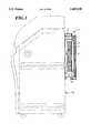
- FIG. 1shows an illustration of a representative filtering system within the scope of this invention.
- Photothermographic imaging mediaare first exposed to radiation to create a latent image and then the media are thermally developed to convert the latent image to a visible image.
- thermal developing systems employed for photothermographyhave been platens (flat or curved), inert fluid baths (e.g., oil baths), and rotating heated drums.
- a cylindrical heating element(either a rounded platen or circular drum) offers the best performance and compactness in a developer unit.
- Such cylindrical developing unitsare shown for example in U.S. Pat. No. 4,518,843 and U.S. patent application Ser. Nos. 07/862,850 and 07/942,633.
- ventscan be located above the thermal drum or platen. As heat rises, it is easier to provide the vent at a location to where the heated gases rise.
- the vent intended to collect the vapors from the heating drumdoes not have to be located directly above the drum, particularly when it is assisted by reduced pressure to enhance the flow of gases into the vent stream. However, having the vent above the center of mass of the drum may be convenient.
- the second ventmay also be located within the portion of the processor housing the heating roller or drum, but should be located closer to the stripping point of the media and the drum (the point at which the media and the drum separate from each other) so that there is no longer any thermal conduction between the drum and the media.
- the vent associated with the splitting or separation point on the drummay be located above or to the side or just below that point on the exterior direction within the housing.
- reduced pressuree.g., exhaust fan or pump
- the filter unit 1is preferably attached to the outside of the housing 10 for the processor unit, for compactness and aesthetics. Locating the filter system outside the housing 10 eliminates or reduces problems caused by the heat within the processor unit. For example, the carbon media has been found to have improved capacity at the lower temperatures found outside the processing unit. The cooler temperatures also allow the fatty acids to condense onto surfaces prior to entering the absorbent media. Having the filtering system located outside of the processor housing 10 also allows for ease in maintenance. Finally, the external location enables easy removal of the filter system and replacement with an adaptor which provides a means for attaching the machine to external building vents or ducts.
- the vents from the developing unitscarry heated air and by-product gases to the inlet 2 of the filtering system.
- the heated air and by-product gasesthen enter the first stage of the filtering system, the heat conducting, condensate accumulator 3.
- the warm air stream coming out of the processing chamberis cooled and the higher molecular weight materials, such as fatty acids, condense or precipitate out of the air stream.
- the inventorshave found that in addition to condensing on the surface of the heat conducting, condensate accumulator 3, some fatty acids form solid particles which are carried along in the air stream.
- This heat conducting, condensate accumulator 3may take a variety of different forms such as a long or circuitous path through a high heat conducting material such as a metal, a thermoelectric cooling system (Peltier cell), or a heat exchanger having a cooling fluid, such as cooling water.
- a high heat conducting materialsuch as a metal, a thermoelectric cooling system (Peltier cell), or a heat exchanger having a cooling fluid, such as cooling water.
- a complex heat exchangeris not required, however.
- a suitable, yet simple, system which may be usedis passing the heated air down the length of a metal matrix.
- An aluminum meshhas been found to work well as it provides a large amount of cooling surface over which the heated air can pass and on which the condensates may accumulate. The length and thickness or number of layers of the mesh may be varied as necessary to provide sufficient cooling and condensation surfaces.
- fatty acidsare the predominant material accumulated. Applicants have found that the fatty acids not only condense but also solidify when passing through the heat conducting, condensate accumulator. While most of the solids stick to the metal matrix some solid particulates are carried along in the exhaust air stream.
- the process airpasses through a particulate filter 4.
- the need for the particulate filter 4was determined when the inventors noted that some fatty acids formed solid particulates upon cooling which were carried along by the air stream.
- the particulate filter 4removes other airborne debris which may be generated in the processor.
- the particulate filter 4removes these airborne particulates which might other wise contaminate or cause blockages in the absorbent block 5.
- the particulate filter 4also reduces the likelihood of particulates being exhausted into the user's environment. Any particulate air filter may be used.
- the choice of the particulate filtermay be in part a balance of low pressure drop and high removal efficiency.
- a bulky particulate filteris less desirable since the entire filter system is preferably mounted on the outside of the processor housing. FiltreteTM filters work well since they have high efficiency, cause relatively low pressure drops, and are not unreasonably bulky.
- the absorbent block 5removes odorous materials, such as aldehydes, from the air stream.
- the absorbent materials used in this third stageshould be selected so that it effectively removes the odor causing vapors released during thermal processing of the photothermographic element. These vapors usually include one or all of the following: aldehydes, and particularly butyraldehyde, toluene, acetic acid, methyl ethyl ketone, and butyric acid.
- the absorbent block 5may be composed of a single odor absorbing material or may comprise two or more different types of odor absorbing material.
- the absorbent materialsmay be combined by either mixing the various filtering and reactive materials together into a well distributed mixture, forming a two or more layered filter element with the various filtering activities distributed in distinct layers, or by making two distinct filter materials which are placed next to each other within the filter cartridge.
- the absorbent materialmay be provided in various forms including a packed bed. However, bonded absorbent particulate filter media have certain advantages, including a generally lower pressure drop.
- Bonded absorbent particulate filter mediaare described for example in U.S. Pat. Nos. 5,033,465 and 5,078,132.
- the bonded filter mediamay be described as spaced absorbent granules or particles which are bonded to one another by adherent binder particles distributed between the absorbent granules.
- the binder particlesdo not form a continuous phase surrounding the absorbent particles, but allow for gases to move throughout the bonded structure.
- the binder particlesare preferably very evenly distributed throughout the bonded structure and around the absorbent granules to provide uniformity to the flow characteristics of the bonded filter medium.
- the binder particlesmay be comprised of a polymer which has particularly desired chemically reactive or chelating sites in or pendant from the polymer chain.
- any thermally softenable particulate bindercan be used as the binder particle, but polyolefins, nylons, and polyurethanes are preferred. Mixtures of polymeric binder particles may also be used to tailor the structural and absorbance characteristics of the filter media.
- the bonded carbonalso maintains its shape well, which helps to eliminate the formation of channels through the filter.
- the preferred absorbent materialis carbon, and particularly activated carbon granules.
- the two different carbonsmay be mixed or may form two different sections of the block in series.
- Activated carbon particlesare commercially available and are generally designated in the art by their absorptive characteristics with respect to specific types of materials.
- activated charcoalis commercially available from suppliers under designations such as "Formaldehyde Sorbent,” “Organic Vapor Sorbent,” Acid Gas Sorbent,” and “Organic Vapor/Acid Gas Sorbent.”
- any carbon filter materialmay be used in the practice of the present invention, with various levels of benefits over many other commercially available filter materials.
- the activated carbon particles, and most especially the Organic Vapor/Acid Gas Sorbent and formaldehyde sorbent types of activated carbon particlesare preferred. Filters made from bonded absorbent particles, and particularly bonded carbon, were found to be better filter materials for vent streams from photothermographic developing units as compared to zeolites, impregnated foams, or coated fibers.
- the bonded absorbent particulate fibers used in the practice of the present inventionshowed more uniform absorption of material throughout the body of the filter (reducing channelling and clogging of the filter cartridge), greater absorption capacity, and the ability to absorb a more diverse range of materials exiting the thermal developer unit.
- the outlet of the filter systemis equipped with a fan 6 that pulls the air from the processor through the filter. Locating the fan 6 at the exit of the filtering system, rather than at the inlet, is advantageous in that the fan 6 is protected from fatty acid deposits and other materials which may damage the fan 6.
- the materials selected for the construction of the frame, cartridge, etcare not critical. Any material which can be formed into the appropriate shape with meaningful structural properties can be used. It is preferred to use metals, polymeric materials, composites or the like for the construction of these parts of the equipment.
Landscapes
- Physics & Mathematics (AREA)
- General Physics & Mathematics (AREA)
- Photographic Developing Apparatuses (AREA)
- Filtering Materials (AREA)
- Non-Silver Salt Photosensitive Materials And Non-Silver Salt Photography (AREA)
- Treating Waste Gases (AREA)
- Separation Of Gases By Adsorption (AREA)
- Filtering Of Dispersed Particles In Gases (AREA)
- Solid-Sorbent Or Filter-Aiding Compositions (AREA)
- Optical Filters (AREA)
- Organic Low-Molecular-Weight Compounds And Preparation Thereof (AREA)
Abstract
Description
Claims (12)
Priority Applications (10)
| Application Number | Priority Date | Filing Date | Title |
|---|---|---|---|
| US08/322,977US5469238A (en) | 1994-10-13 | 1994-10-13 | Filter for a photothermographic developer |
| US08/468,526US5502533A (en) | 1994-10-13 | 1995-06-06 | Filter for photothermographic developer |
| EP95930231AEP0786104B1 (en) | 1994-10-13 | 1995-08-18 | Filter for a photothermographic developer |
| AU33690/95AAU3369095A (en) | 1994-10-13 | 1995-08-18 | Filter for a photothermographic developer |
| PCT/US1995/010604WO1996012213A1 (en) | 1994-10-13 | 1995-08-18 | Filter for a photothermographic developer |
| DE69508954TDE69508954T2 (en) | 1994-10-13 | 1995-08-18 | FILTER FOR PHOTOTHERMOGRAPHIC DEVELOPMENT DEVICE |
| AT95930231TATE178721T1 (en) | 1994-10-13 | 1995-08-18 | FILTER FOR PHOTOTHERMOGRAPHIC DEVELOPER |
| CN95195629ACN1160443A (en) | 1994-10-13 | 1995-08-18 | Filter for photothermographic developer |
| JP51320796AJP3766688B2 (en) | 1994-10-13 | 1995-08-18 | Filter for photothermographic development equipment |
| IL11511495AIL115114A0 (en) | 1994-10-13 | 1995-08-31 | Filter for a photothermographic developer |
Applications Claiming Priority (1)
| Application Number | Priority Date | Filing Date | Title |
|---|---|---|---|
| US08/322,977US5469238A (en) | 1994-10-13 | 1994-10-13 | Filter for a photothermographic developer |
Related Child Applications (1)
| Application Number | Title | Priority Date | Filing Date |
|---|---|---|---|
| US08/468,526ContinuationUS5502533A (en) | 1994-10-13 | 1995-06-06 | Filter for photothermographic developer |
Publications (1)
| Publication Number | Publication Date |
|---|---|
| US5469238Atrue US5469238A (en) | 1995-11-21 |
Family
ID=23257265
Family Applications (2)
| Application Number | Title | Priority Date | Filing Date |
|---|---|---|---|
| US08/322,977Expired - LifetimeUS5469238A (en) | 1994-10-13 | 1994-10-13 | Filter for a photothermographic developer |
| US08/468,526Expired - LifetimeUS5502533A (en) | 1994-10-13 | 1995-06-06 | Filter for photothermographic developer |
Family Applications After (1)
| Application Number | Title | Priority Date | Filing Date |
|---|---|---|---|
| US08/468,526Expired - LifetimeUS5502533A (en) | 1994-10-13 | 1995-06-06 | Filter for photothermographic developer |
Country Status (9)
| Country | Link |
|---|---|
| US (2) | US5469238A (en) |
| EP (1) | EP0786104B1 (en) |
| JP (1) | JP3766688B2 (en) |
| CN (1) | CN1160443A (en) |
| AT (1) | ATE178721T1 (en) |
| AU (1) | AU3369095A (en) |
| DE (1) | DE69508954T2 (en) |
| IL (1) | IL115114A0 (en) |
| WO (1) | WO1996012213A1 (en) |
Cited By (7)
| Publication number | Priority date | Publication date | Assignee | Title |
|---|---|---|---|---|
| WO1997021150A1 (en)* | 1995-12-04 | 1997-06-12 | Imation Corp. | Photothermographic thermal processor filtration system |
| US5895592A (en)* | 1996-12-19 | 1999-04-20 | Imation Corp. | Apparatus and method for thermally processing an imaging material employing a system for reducing fogging on the imaging material during thermal processing |
| US5986238A (en)* | 1996-12-19 | 1999-11-16 | Imation Corporation | Apparatus and method for thermally processing an imaging material employing means for reducing fogging on the imaging material during thermal processing |
| US6524781B2 (en)* | 2000-06-15 | 2003-02-25 | Konica Corporation | Photothermographic material |
| US7064295B1 (en)* | 2005-02-10 | 2006-06-20 | Eastman Kodak Company | Thermal processor having flexible duct |
| US20070144346A1 (en)* | 2005-12-22 | 2007-06-28 | Struble Kent R | Thermal processor with contaminant removal cartridge |
| US20090123881A1 (en)* | 2001-08-02 | 2009-05-14 | Fujifilm Corporation | Photothermographic material and image formation method |
Families Citing this family (5)
| Publication number | Priority date | Publication date | Assignee | Title |
|---|---|---|---|---|
| USD425549S (en)* | 1999-07-14 | 2000-05-23 | Imation Corp. | Filter for use with an electrographic imaging system |
| US6238467B1 (en)* | 1999-09-24 | 2001-05-29 | Gore Enterprise Holdings, Inc. | Rigid multi-functional filter assembly |
| US7924300B2 (en)* | 2006-08-07 | 2011-04-12 | Carestream Health, Inc. | Processor for imaging media |
| US20110091822A1 (en)* | 2007-03-12 | 2011-04-21 | Scufsa John R | Thermal processor employing a temperature compensation system |
| JP5951481B2 (en)* | 2009-04-15 | 2016-07-13 | ナノミックス・インコーポレーテッド | Portable unit for sampling and detecting exhalation and method for detecting an analyte in exhalation |
Citations (10)
| Publication number | Priority date | Publication date | Assignee | Title |
|---|---|---|---|---|
| US3457075A (en)* | 1964-04-27 | 1969-07-22 | Minnesota Mining & Mfg | Sensitized sheet containing an organic silver salt,a reducing agent and a catalytic proportion of silver halide |
| US3570383A (en)* | 1967-11-06 | 1971-03-16 | Scott Paper Co | Apparatus for developing and fixing a thermodevelopable photographic medium |
| US3679369A (en)* | 1969-05-13 | 1972-07-25 | Hideo Hashimoto | Deodorization device |
| US4059409A (en)* | 1976-03-12 | 1977-11-22 | Blu-Ray, Incorporated | Apparatus for eliminating ammonia fumes emanating from diazo copiers |
| US4166728A (en)* | 1973-07-26 | 1979-09-04 | Hoechst Aktiengesellschaft | Process for conducting ammonia in copying machines |
| US4473282A (en)* | 1981-06-30 | 1984-09-25 | Norman Michlin | Diazo copy machine with ammonia vapor absorber |
| US4518843A (en)* | 1982-09-01 | 1985-05-21 | Westinghouse Electric Corp. | Laser lens and light assembly |
| US5023654A (en)* | 1988-10-31 | 1991-06-11 | Brother Kogyo Kabushiki Kaisha | Thermal fixing device for image recording apparatus |
| US5033465A (en)* | 1985-08-28 | 1991-07-23 | Minnesota Mining And Manufacturing Company | Bonded adsorbent structures and respirators incorporating same |
| US5078132A (en)* | 1985-08-28 | 1992-01-07 | Minnesota Mining And Manufacturing Company | Bonded adsorbent structures and respirators incorporating same |
Family Cites Families (3)
| Publication number | Priority date | Publication date | Assignee | Title |
|---|---|---|---|---|
| US3798790A (en)* | 1973-01-04 | 1974-03-26 | Perkin Elmer Corp | Heat processor for photographic films |
| DE3221432C2 (en)* | 1982-06-07 | 1985-01-10 | Jobo Labortechnik Gmbh & Co Kg, 5270 Gummersbach | Device for developing photographic material in a rotating drum |
| JPH0545850A (en)* | 1991-02-19 | 1993-02-26 | Seiko Epson Corp | Gas removing device |
- 1994
- 1994-10-13USUS08/322,977patent/US5469238A/ennot_activeExpired - Lifetime
- 1995
- 1995-06-06USUS08/468,526patent/US5502533A/ennot_activeExpired - Lifetime
- 1995-08-18ATAT95930231Tpatent/ATE178721T1/ennot_activeIP Right Cessation
- 1995-08-18DEDE69508954Tpatent/DE69508954T2/ennot_activeExpired - Lifetime
- 1995-08-18JPJP51320796Apatent/JP3766688B2/ennot_activeExpired - Fee Related
- 1995-08-18EPEP95930231Apatent/EP0786104B1/ennot_activeExpired - Lifetime
- 1995-08-18AUAU33690/95Apatent/AU3369095A/ennot_activeAbandoned
- 1995-08-18WOPCT/US1995/010604patent/WO1996012213A1/enactiveIP Right Grant
- 1995-08-18CNCN95195629Apatent/CN1160443A/enactivePending
- 1995-08-31ILIL11511495Apatent/IL115114A0/enunknown
Patent Citations (10)
| Publication number | Priority date | Publication date | Assignee | Title |
|---|---|---|---|---|
| US3457075A (en)* | 1964-04-27 | 1969-07-22 | Minnesota Mining & Mfg | Sensitized sheet containing an organic silver salt,a reducing agent and a catalytic proportion of silver halide |
| US3570383A (en)* | 1967-11-06 | 1971-03-16 | Scott Paper Co | Apparatus for developing and fixing a thermodevelopable photographic medium |
| US3679369A (en)* | 1969-05-13 | 1972-07-25 | Hideo Hashimoto | Deodorization device |
| US4166728A (en)* | 1973-07-26 | 1979-09-04 | Hoechst Aktiengesellschaft | Process for conducting ammonia in copying machines |
| US4059409A (en)* | 1976-03-12 | 1977-11-22 | Blu-Ray, Incorporated | Apparatus for eliminating ammonia fumes emanating from diazo copiers |
| US4473282A (en)* | 1981-06-30 | 1984-09-25 | Norman Michlin | Diazo copy machine with ammonia vapor absorber |
| US4518843A (en)* | 1982-09-01 | 1985-05-21 | Westinghouse Electric Corp. | Laser lens and light assembly |
| US5033465A (en)* | 1985-08-28 | 1991-07-23 | Minnesota Mining And Manufacturing Company | Bonded adsorbent structures and respirators incorporating same |
| US5078132A (en)* | 1985-08-28 | 1992-01-07 | Minnesota Mining And Manufacturing Company | Bonded adsorbent structures and respirators incorporating same |
| US5023654A (en)* | 1988-10-31 | 1991-06-11 | Brother Kogyo Kabushiki Kaisha | Thermal fixing device for image recording apparatus |
Non-Patent Citations (2)
| Title |
|---|
| "Model 258B Continuous Thermal Processor" 3M Brand, Illustrated Parts Manual, Microfilm Systems, 3M Company, May 1975, 78-6969-1537-6. |
| Model 258B Continuous Thermal Processor 3M Brand, Illustrated Parts Manual, Microfilm Systems, 3M Company, May 1975, 78 6969 1537 6.* |
Cited By (9)
| Publication number | Priority date | Publication date | Assignee | Title |
|---|---|---|---|---|
| WO1997021150A1 (en)* | 1995-12-04 | 1997-06-12 | Imation Corp. | Photothermographic thermal processor filtration system |
| US5895592A (en)* | 1996-12-19 | 1999-04-20 | Imation Corp. | Apparatus and method for thermally processing an imaging material employing a system for reducing fogging on the imaging material during thermal processing |
| US5986238A (en)* | 1996-12-19 | 1999-11-16 | Imation Corporation | Apparatus and method for thermally processing an imaging material employing means for reducing fogging on the imaging material during thermal processing |
| US6524781B2 (en)* | 2000-06-15 | 2003-02-25 | Konica Corporation | Photothermographic material |
| US20090123881A1 (en)* | 2001-08-02 | 2009-05-14 | Fujifilm Corporation | Photothermographic material and image formation method |
| US7695898B2 (en)* | 2001-08-02 | 2010-04-13 | Fujifilm Corporation | Photothermographic material and image formation method |
| US7064295B1 (en)* | 2005-02-10 | 2006-06-20 | Eastman Kodak Company | Thermal processor having flexible duct |
| US20070144346A1 (en)* | 2005-12-22 | 2007-06-28 | Struble Kent R | Thermal processor with contaminant removal cartridge |
| US7510596B2 (en) | 2005-12-22 | 2009-03-31 | Carestream Health, Inc. | Thermal processor with contaminant removal cartridge |
Also Published As
| Publication number | Publication date |
|---|---|
| AU3369095A (en) | 1996-05-06 |
| EP0786104A1 (en) | 1997-07-30 |
| WO1996012213A1 (en) | 1996-04-25 |
| DE69508954T2 (en) | 1999-12-02 |
| DE69508954D1 (en) | 1999-05-12 |
| US5502533A (en) | 1996-03-26 |
| CN1160443A (en) | 1997-09-24 |
| JPH10507403A (en) | 1998-07-21 |
| IL115114A0 (en) | 1995-12-08 |
| EP0786104B1 (en) | 1999-04-07 |
| ATE178721T1 (en) | 1999-04-15 |
| JP3766688B2 (en) | 2006-04-12 |
Similar Documents
| Publication | Publication Date | Title |
|---|---|---|
| US5469238A (en) | Filter for a photothermographic developer | |
| JP5595627B2 (en) | Filters that use both acidic polymers and physisorption media | |
| US20090098491A1 (en) | Method and apparatus for thermal development | |
| US5600396A (en) | Photothermographic thermal processor filtration system | |
| EP0759191B1 (en) | Absorption of gases in a device or a process for developing photothermographic media | |
| US6512900B2 (en) | Image forming apparatus having alarm which indicates carrier solvent filter replacement or lack of solvent supply | |
| JP2009521715A (en) | Thermal processor with contaminant removal cartridge | |
| US6041201A (en) | Apparatus for filtering solvent of liquid electrophotographic printer | |
| CN101022943A (en) | Apparatus for the rapid development of photosensitive printing elements | |
| JPH09204121A (en) | Electrophotographic printer | |
| JP2003190736A (en) | Deodorizing filter unit for photothermographic system | |
| JP2002278038A (en) | Heat developing device | |
| JP2000237739A (en) | Vapor condensation device, photosensitive material processing device and photographic processing waste treating device | |
| JP3222070B2 (en) | Ash detoxification equipment | |
| JP2001129536A (en) | Photographic waste solution treatment apparatus | |
| JPH02107392A (en) | Apparatus for treating waste liquid produced in photographic processing | |
| JP2002023338A (en) | Method for capturing dispersed molecule in development of heat developable material | |
| JPH0367259A (en) | Photosensitive material storage container | |
| JPH05216196A (en) | Automatic developing machine | |
| JPS63128346A (en) | Treating device for waste developing solution | |
| JPS63137129A (en) | Method and device for recovering silver from photographic processing wastes | |
| JPH05192650A (en) | Treatment of processing waste liquid of nonsilver salt photosensitive material and treating device | |
| JPS6326656A (en) | Photosensitive material processor for processing photosensitive material with processing solution | |
| JPS58105179A (en) | Flash fixation device | |
| JP2001142180A (en) | Waste photographic processing liquid treating device |
Legal Events
| Date | Code | Title | Description |
|---|---|---|---|
| AS | Assignment | Owner name:MINNESOTA MINING AND MANUFACTURING COMPANY, MINNES Free format text:ASSIGNMENT OF ASSIGNORS INTEREST;ASSIGNOR:BIEGLER, ROBERT M.;REEL/FRAME:007240/0294 Effective date:19941013 | |
| STCF | Information on status: patent grant | Free format text:PATENTED CASE | |
| FEPP | Fee payment procedure | Free format text:PAYOR NUMBER ASSIGNED (ORIGINAL EVENT CODE: ASPN); ENTITY STATUS OF PATENT OWNER: LARGE ENTITY | |
| FPAY | Fee payment | Year of fee payment:4 | |
| AS | Assignment | Owner name:EASTMAN KODAK COMPANY, NEW YORK Free format text:ASSIGNMENT OF ASSIGNORS INTEREST;ASSIGNOR:MINNESOTA MINING AND MANUFACTURING COMPANY;REEL/FRAME:010793/0377 Effective date:20000310 | |
| FPAY | Fee payment | Year of fee payment:8 | |
| REMI | Maintenance fee reminder mailed | ||
| FPAY | Fee payment | Year of fee payment:12 | |
| AS | Assignment | Owner name:CREDIT SUISSE, CAYMAN ISLANDS BRANCH, AS ADMINISTR Free format text:FIRST LIEN OF INTELLECTUAL PROPERTY SECURITY AGREEMENT;ASSIGNOR:CARESTREAM HEALTH, INC.;REEL/FRAME:019649/0454 Effective date:20070430 Owner name:CREDIT SUISSE, CAYMAN ISLANDS BRANCH, AS ADMINISTR Free format text:SECOND LIEN INTELLECTUAL PROPERTY SECURITY AGREEME;ASSIGNOR:CARESTREAM HEALTH, INC.;REEL/FRAME:019773/0319 Effective date:20070430 | |
| AS | Assignment | Owner name:CARESTREAM HEALTH, INC., NEW YORK Free format text:ASSIGNMENT OF ASSIGNORS INTEREST;ASSIGNOR:EASTMAN KODAK COMPANY;REEL/FRAME:020741/0126 Effective date:20070501 Owner name:CARESTREAM HEALTH, INC., NEW YORK Free format text:ASSIGNMENT OF ASSIGNORS INTEREST;ASSIGNOR:EASTMAN KODAK COMPANY;REEL/FRAME:020756/0500 Effective date:20070501 Owner name:CARESTREAM HEALTH, INC.,NEW YORK Free format text:ASSIGNMENT OF ASSIGNORS INTEREST;ASSIGNOR:EASTMAN KODAK COMPANY;REEL/FRAME:020741/0126 Effective date:20070501 Owner name:CARESTREAM HEALTH, INC.,NEW YORK Free format text:ASSIGNMENT OF ASSIGNORS INTEREST;ASSIGNOR:EASTMAN KODAK COMPANY;REEL/FRAME:020756/0500 Effective date:20070501 | |
| AS | Assignment | Owner name:CARESTREAM HEALTH, INC., NEW YORK Free format text:RELEASE OF SECURITY INTEREST IN INTELLECTUAL PROPERTY (FIRST LIEN);ASSIGNOR:CREDIT SUISSE AG, CAYMAN ISLANDS BRANCH;REEL/FRAME:026069/0012 Effective date:20110225 | |
| AS | Assignment | Owner name:CREDIT SUISSE AG, CAYMAN ISLANDS BRANCH, NEW YORK Free format text:INTELLECTUAL PROPERTY SECURITY AGREEMENT;ASSIGNORS:CARESTREAM HEALTH, INC.;CARESTREAM DENTAL, LLC;QUANTUM MEDICAL IMAGING, L.L.C.;AND OTHERS;REEL/FRAME:026269/0411 Effective date:20110225 | |
| AS | Assignment | Owner name:CARESTREAM HEALTH, INC., NEW YORK Free format text:RELEASE OF SECURITY INTEREST IN INTELLECTUAL PROPERTY (SECOND LIEN);ASSIGNOR:CREDIT SUISSE AG, CAYMAN ISLANDS BRANCH;REEL/FRAME:027851/0812 Effective date:20110225 | |
| AS | Assignment | Owner name:CREDIT SUISSE AG, CAYMAN ISLANDS BRANCH, NEW YORK Free format text:AMENDED AND RESTATED INTELLECTUAL PROPERTY SECURITY AGREEMENT (FIRST LIEN);ASSIGNORS:CARESTREAM HEALTH, INC.;CARESTREAM DENTAL LLC;QUANTUM MEDICAL IMAGING, L.L.C.;AND OTHERS;REEL/FRAME:030711/0648 Effective date:20130607 | |
| AS | Assignment | Owner name:CREDIT SUISSE AG, CAYMAN ISLANDS BRANCH, NEW YORK Free format text:SECOND LIEN INTELLECTUAL PROPERTY SECURITY AGREEMENT;ASSIGNORS:CARESTREAM HEALTH, INC.;CARESTREAM DENTAL LLC;QUANTUM MEDICAL IMAGING, L.L.C.;AND OTHERS;REEL/FRAME:030724/0154 Effective date:20130607 | |
| AS | Assignment | Owner name:TROPHY DENTAL INC., GEORGIA Free format text:RELEASE BY SECURED PARTY;ASSIGNOR:CREDIT SUISSE AG, CAYMAN ISLANDS BRANCH;REEL/FRAME:061681/0380 Effective date:20220930 Owner name:QUANTUM MEDICAL HOLDINGS, LLC, NEW YORK Free format text:RELEASE BY SECURED PARTY;ASSIGNOR:CREDIT SUISSE AG, CAYMAN ISLANDS BRANCH;REEL/FRAME:061681/0380 Effective date:20220930 Owner name:QUANTUM MEDICAL IMAGING, L.L.C., NEW YORK Free format text:RELEASE BY SECURED PARTY;ASSIGNOR:CREDIT SUISSE AG, CAYMAN ISLANDS BRANCH;REEL/FRAME:061681/0380 Effective date:20220930 Owner name:CARESTREAM DENTAL, LLC, GEORGIA Free format text:RELEASE BY SECURED PARTY;ASSIGNOR:CREDIT SUISSE AG, CAYMAN ISLANDS BRANCH;REEL/FRAME:061681/0380 Effective date:20220930 Owner name:CARESTREAM HEALTH, INC., NEW YORK Free format text:RELEASE BY SECURED PARTY;ASSIGNOR:CREDIT SUISSE AG, CAYMAN ISLANDS BRANCH;REEL/FRAME:061681/0380 Effective date:20220930 Owner name:TROPHY DENTAL INC., NEW YORK Free format text:RELEASE OF SECURITY INTEREST IN INTELLECTUAL PROPERTY (FIRST LIEN);ASSIGNOR:CREDIT SUISSE AG, CAYMAN ISLANDS BRANCH;REEL/FRAME:061683/0441 Effective date:20220930 Owner name:QUANTUM MEDICAL IMAGING, L.L.C., NEW YORK Free format text:RELEASE OF SECURITY INTEREST IN INTELLECTUAL PROPERTY (FIRST LIEN);ASSIGNOR:CREDIT SUISSE AG, CAYMAN ISLANDS BRANCH;REEL/FRAME:061683/0441 Effective date:20220930 Owner name:CARESTREAM DENTAL LLC, GEORGIA Free format text:RELEASE OF SECURITY INTEREST IN INTELLECTUAL PROPERTY (FIRST LIEN);ASSIGNOR:CREDIT SUISSE AG, CAYMAN ISLANDS BRANCH;REEL/FRAME:061683/0441 Effective date:20220930 Owner name:CARESTREAM HEALTH, INC., NEW YORK Free format text:RELEASE OF SECURITY INTEREST IN INTELLECTUAL PROPERTY (FIRST LIEN);ASSIGNOR:CREDIT SUISSE AG, CAYMAN ISLANDS BRANCH;REEL/FRAME:061683/0441 Effective date:20220930 Owner name:TROPHY DENTAL INC., GEORGIA Free format text:RELEASE OF SECURITY INTEREST IN INTELLECTUAL PROPERTY (SECOND LIEN);ASSIGNOR:CREDIT SUISSE AG, CAYMAN ISLANDS BRANCH;REEL/FRAME:061683/0601 Effective date:20220930 Owner name:QUANTUM MEDICAL IMAGING, L.L.C., NEW YORK Free format text:RELEASE OF SECURITY INTEREST IN INTELLECTUAL PROPERTY (SECOND LIEN);ASSIGNOR:CREDIT SUISSE AG, CAYMAN ISLANDS BRANCH;REEL/FRAME:061683/0601 Effective date:20220930 Owner name:CARESTREAM DENTAL LLC, GEORGIA Free format text:RELEASE OF SECURITY INTEREST IN INTELLECTUAL PROPERTY (SECOND LIEN);ASSIGNOR:CREDIT SUISSE AG, CAYMAN ISLANDS BRANCH;REEL/FRAME:061683/0601 Effective date:20220930 Owner name:CARESTREAM HEALTH, INC., NEW YORK Free format text:RELEASE OF SECURITY INTEREST IN INTELLECTUAL PROPERTY (SECOND LIEN);ASSIGNOR:CREDIT SUISSE AG, CAYMAN ISLANDS BRANCH;REEL/FRAME:061683/0601 Effective date:20220930 |