US5468248A - Endoscopic inflatable retraction devices for separating layers of tissue - Google Patents
Endoscopic inflatable retraction devices for separating layers of tissueDownload PDFInfo
- Publication number
- US5468248A US5468248AUS08/111,211US11121193AUS5468248AUS 5468248 AUS5468248 AUS 5468248AUS 11121193 AUS11121193 AUS 11121193AUS 5468248 AUS5468248 AUS 5468248A
- Authority
- US
- United States
- Prior art keywords
- tissue
- main
- layer
- envelope
- cannula
- Prior art date
- Legal status (The legal status is an assumption and is not a legal conclusion. Google has not performed a legal analysis and makes no representation as to the accuracy of the status listed.)
- Expired - Lifetime
Links
Images


Classifications
- A—HUMAN NECESSITIES
- A61—MEDICAL OR VETERINARY SCIENCE; HYGIENE
- A61B—DIAGNOSIS; SURGERY; IDENTIFICATION
- A61B17/00—Surgical instruments, devices or methods
- A61B17/02—Surgical instruments, devices or methods for holding wounds open, e.g. retractors; Tractors
- A61B17/0218—Surgical instruments, devices or methods for holding wounds open, e.g. retractors; Tractors for minimally invasive surgery
- A—HUMAN NECESSITIES
- A61—MEDICAL OR VETERINARY SCIENCE; HYGIENE
- A61B—DIAGNOSIS; SURGERY; IDENTIFICATION
- A61B17/00—Surgical instruments, devices or methods
- A61B17/02—Surgical instruments, devices or methods for holding wounds open, e.g. retractors; Tractors
- A61B17/0281—Abdominal wall lifters
- A—HUMAN NECESSITIES
- A61—MEDICAL OR VETERINARY SCIENCE; HYGIENE
- A61B—DIAGNOSIS; SURGERY; IDENTIFICATION
- A61B17/00—Surgical instruments, devices or methods
- A61B17/22—Implements for squeezing-off ulcers or the like on inner organs of the body; Implements for scraping-out cavities of body organs, e.g. bones; for invasive removal or destruction of calculus using mechanical vibrations; for removing obstructions in blood vessels, not otherwise provided for
- A61B17/22031—Gripping instruments, e.g. forceps, for removing or smashing calculi
- A61B17/22032—Gripping instruments, e.g. forceps, for removing or smashing calculi having inflatable gripping elements
- A—HUMAN NECESSITIES
- A61—MEDICAL OR VETERINARY SCIENCE; HYGIENE
- A61B—DIAGNOSIS; SURGERY; IDENTIFICATION
- A61B17/00—Surgical instruments, devices or methods
- A61B17/34—Trocars; Puncturing needles
- A61B17/3417—Details of tips or shafts, e.g. grooves, expandable, bendable; Multiple coaxial sliding cannulas, e.g. for dilating
- A—HUMAN NECESSITIES
- A61—MEDICAL OR VETERINARY SCIENCE; HYGIENE
- A61B—DIAGNOSIS; SURGERY; IDENTIFICATION
- A61B90/00—Instruments, implements or accessories specially adapted for surgery or diagnosis and not covered by any of the groups A61B1/00 - A61B50/00, e.g. for luxation treatment or for protecting wound edges
- A61B90/50—Supports for surgical instruments, e.g. articulated arms
- A—HUMAN NECESSITIES
- A61—MEDICAL OR VETERINARY SCIENCE; HYGIENE
- A61B—DIAGNOSIS; SURGERY; IDENTIFICATION
- A61B17/00—Surgical instruments, devices or methods
- A61B17/34—Trocars; Puncturing needles
- A61B17/3462—Trocars; Puncturing needles with means for changing the diameter or the orientation of the entrance port of the cannula, e.g. for use with different-sized instruments, reduction ports, adapter seals
- A—HUMAN NECESSITIES
- A61—MEDICAL OR VETERINARY SCIENCE; HYGIENE
- A61B—DIAGNOSIS; SURGERY; IDENTIFICATION
- A61B17/00—Surgical instruments, devices or methods
- A61B17/00234—Surgical instruments, devices or methods for minimally invasive surgery
- A61B2017/00238—Type of minimally invasive operation
- A61B2017/00261—Discectomy
- A—HUMAN NECESSITIES
- A61—MEDICAL OR VETERINARY SCIENCE; HYGIENE
- A61B—DIAGNOSIS; SURGERY; IDENTIFICATION
- A61B17/00—Surgical instruments, devices or methods
- A61B2017/00535—Surgical instruments, devices or methods pneumatically or hydraulically operated
- A—HUMAN NECESSITIES
- A61—MEDICAL OR VETERINARY SCIENCE; HYGIENE
- A61B—DIAGNOSIS; SURGERY; IDENTIFICATION
- A61B17/00—Surgical instruments, devices or methods
- A61B2017/00535—Surgical instruments, devices or methods pneumatically or hydraulically operated
- A61B2017/00557—Surgical instruments, devices or methods pneumatically or hydraulically operated inflatable
- A—HUMAN NECESSITIES
- A61—MEDICAL OR VETERINARY SCIENCE; HYGIENE
- A61B—DIAGNOSIS; SURGERY; IDENTIFICATION
- A61B17/00—Surgical instruments, devices or methods
- A61B17/30—Surgical pincettes, i.e. surgical tweezers without pivotal connections
- A61B2017/306—Surgical pincettes, i.e. surgical tweezers without pivotal connections holding by means of suction
- A—HUMAN NECESSITIES
- A61—MEDICAL OR VETERINARY SCIENCE; HYGIENE
- A61B—DIAGNOSIS; SURGERY; IDENTIFICATION
- A61B17/00—Surgical instruments, devices or methods
- A61B17/32—Surgical cutting instruments
- A61B2017/320044—Blunt dissectors
- A61B2017/320048—Balloon dissectors
- A—HUMAN NECESSITIES
- A61—MEDICAL OR VETERINARY SCIENCE; HYGIENE
- A61B—DIAGNOSIS; SURGERY; IDENTIFICATION
- A61B17/00—Surgical instruments, devices or methods
- A61B17/34—Trocars; Puncturing needles
- A61B2017/348—Means for supporting the trocar against the body or retaining the trocar inside the body
- A61B2017/3482—Means for supporting the trocar against the body or retaining the trocar inside the body inside
- A61B2017/3484—Anchoring means, e.g. spreading-out umbrella-like structure
- A61B2017/3486—Balloon
- A—HUMAN NECESSITIES
- A61—MEDICAL OR VETERINARY SCIENCE; HYGIENE
- A61B—DIAGNOSIS; SURGERY; IDENTIFICATION
- A61B90/00—Instruments, implements or accessories specially adapted for surgery or diagnosis and not covered by any of the groups A61B1/00 - A61B50/00, e.g. for luxation treatment or for protecting wound edges
- A61B90/30—Devices for illuminating a surgical field, the devices having an interrelation with other surgical devices or with a surgical procedure
- A61B2090/306—Devices for illuminating a surgical field, the devices having an interrelation with other surgical devices or with a surgical procedure using optical fibres
Definitions
- a herniais the protrusion of part of a body pan or structure through a defect in the wall of a surrounding structure. Most commonly, a hernia is the protrusion of part of abdominal contents, including bowel, through a tear or weakness in the abdominal wall, or through the inguinal canal into the scrotum.
- the mesh patchhas a rough surface that can irritate the bowel and cause adhesions. It is therefore preferred to install the patch properitoneally.
- the mesh patchis preferably attached to the properitoneal fascia of the abdominal wall, and covered by the peritoneum. To attach the mesh patch to the properitoneal fascia, the peritoneum must be dissected from the properitoneal fascia. This is a difficult process. There is a risk of puncturing the peritoneum. Moreover, strands of properitoneal fat interconnecting the peritoneum and the properitoneal fascia make it difficult to see the site of the hernia.
- the bellyis insufflated.
- An incisionis made in the abdominal wall close to the site of the hernia.
- the incisionis made through the abdominal wall as far as the properitoneal fat layer.
- the peritoneumis then blunt dissected from the properitoneal fat layer by passing a finger or a rigid probe through the incision and sweeping the finger or rigid probe under the peritoneum.
- the space between the peritoneum and the properitoneal fat layeris insufflated to provide a working space in which to apply the mesh patch to the properitoneal fascia.
- U.S. patent application Ser. No. 794,590discloses a laparoscopic hernia repair technique that enables a mesh patch to be attached to the properitoneal fascia without breaching the peritoneum.
- An incisionis made through the abdominal wall as far as the properitoneal fat layer.
- a multi-chambered inflatable retraction deviceis pushed through the incision into contact with the peritoneum, and is used to separate the peritoneum from the underlying layers.
- the main end chamber of the inflatable retraction deviceis then inflated to elongate the inflatable retraction device towards the site of the hernia.
- the inflatable retraction devicegently separates the peritoneum from the underlying layers.
- a second inflatable chamberis inflated. The second inflatable chamber enables the inflatable retraction device continue to separate the peritoneum from the underlying layers after the main inflatable chamber has been deflated.
- One or more aperturesare then cut in the envelope of the main inflatable chamber to provide access to the site of the hernia for instruments passed into the main chamber.
- instrumentspass through the main chamber situated between the peritoneum and the underlying layers. In this way, a gauze patch can be attached to the properitoneal fascia without breaching the peritoneum.
- the inventionprovides an apparatus for separating a first layer of tissue, such as the peritoneum, from a second layer of tissue, such as the properitoneal fascia.
- the apparatusincludes a main envelope that defines a main inflatable chamber.
- the apparatusalso includes an introducing device for introducing the main envelope in a collapsed state between the first layer of tissue and the second layer of tissue.
- the introducing deviceis also for inflating the main envelope into an expanded state to separate the first layer of tissue from the second layer of tissue, and to create a working space between the first layer of tissue and the second layer of tissue.
- the apparatusincludes an insufflating device for introducing insufflation gas into the working space between the first layer of tissue and the second layer of tissue.
- a main envelope and insufflation gasare provided.
- the main envelopedefines a main inflatable chamber.
- the main envelopeis introduced in a collapsed state between the first layer of tissue and the second layer of tissue.
- the main envelopeis inflated into an expanded state to separate the first layer of tissue from the second layer of tissue, and to create a working space between the first layer of tissue and the second layer of tissue.
- insufflation gasis introduced into the working space between the first layer of tissue and the second layer of tissue.
- the main envelope and the introducing deviceconstitute a first component that separates the first layer of tissue from the second layer of tissue to create the working space.
- the insufflation deviceconstitutes a second component, which insufflates the working space to maintain the separation of the first layer of tissue from the second.
- the insufflation deviceis tubular, has an anchor flange slidably mounted on it, and has a toroidal inflatable chamber at its distal end. The anchor flange and toroidal inflatable chamber together form a gas-tight seal with the second layer of tissue.
- the introducing deviceis used to push the main envelope in a collapsed state through an incision through the second layer of tissue to place the main envelope between the first layer of tissue and the second layer of tissue.
- the main envelopeis then inflated to gently separate the first layer of tissue from the second layer of tissue, and to create a working space between the two layers of tissue.
- An endoscopemay be passed through the bore of the introducing device into the main chamber to observe the extent of separation of the layers of tissue.
- the main envelopeis then returned to a collapsed state, and the main envelope and the introducing device are removed from the incision.
- the insufflating deviceis inserted into the incision so that its distal end projects into the working space between the two layers of tissue.
- the toroidal inflatable chamberis Mated into an expanded state.
- the anchor flangeis slid distally along the insufflating device to compress the second layer of tissue between it and the expanded toroidal inflatable chamber, and thus to form a gas-tight seal.
- Insufflating gasis then passed through the insufflating device into the working space to maintain the separation of the first layer of tissue from the second.
- An endoscopemay be passed through the bore of the insufflating device into the working space to observe within the working space.
- the introducing deviceis also for returning the main envelope to a collapsed state.
- a single elongated tubeprovides the introducing device and the insufflating device.
- the main envelopeis detachable from the single elongated tube.
- the single elongated tubehas an anchor flange slidably mounted on it, and has a toroidal inflatable chamber at its distal end. The anchor flange and toroidal inflatable chamber together form a gas-tight seal with the second layer of tissue.
- the elongated tubeis used to push the main envelope in a collapsed state through an incision through the second layer of tissue to place the main envelope between the first layer of tissue and the second layer of tissue.
- the main envelopeis then inflated to gently separate the first layer of tissue from the second layer of tissue, and to create a working space between the two layers of tissue.
- An endoscopemay be passed through the bore of the single elongated tube into the main chamber to observe the extent of separation of the layers of tissue.
- the main envelopeis then returned to a collapsed state, detached from the elongated tube, and removed from the working space between the layers of tissue through the bore of the elongated tube.
- the toroidal inflatable chamber at the distal end of the elongated tubeis inflated into an expanded state.
- the anchor flangeis slid distally along the elongated tube to compress the second layer of tissue between it and the expanded toroidal inflatable chamber, to form a gas-tight seal.
- Insufflating gasis then passed through the elongated tube into the working space to maintain the separation of the first layer of tissue from the second.
- An endoscopemay be passed through the bore of the single elongated tube into the working space to observe within the working space.
- the introducing deviceis an outer elongated tube
- the insufflating deviceis an inner elongated tube mounted in the bore of the outer elongated tube.
- the proximal ends of the tubesare flexibly coupled together.
- the main envelopeis a cylindrical piece of elastomeric material. One end of the main envelope is everted with respect to the other, and is attached to the distal end of the outer elongated tube. The other end of the main envelope is attached to the distal end of the inner elongated tube.
- the main inflatable chamber defined by the main envelopeis thus substantially toroidal.
- the outer elongated tubehas an anchor flange slidably mounted on it. The anchor flange and the main inflatable chamber together form a gas-tight seal with the second layer of tissue.
- the outer elongated tubeis used to push the main envelope in a collapsed state through an incision through the second layer of tissue to place the main envelope between the first layer of tissue and the second layer of tissue.
- the main envelopeis then inflated to gently separate the first layer of tissue from the second layer of tissue, and to create working a space between the layers of tissue.
- An endoscopemay be passed through the outer elongated tube into the main chamber to observe the extent of separation of the layers of tissue.
- the anchor flangeis slid distally along the introducing device tube to compress the second layer of tissue between it and the main inflatable chamber, to form a gas-tight seal.
- Insufflating gasis then passed through the bore of the inner elongated tube and the bore of the main envelope into the working space to maintain the separation of the first layer of tissue from the second.
- An endoscopemay be passed through the bore of the inner elongated tube and the bore of the main envelope into the working space to observe within the working space.
- the abdominal wallincludes the peritoneum and an underlying layer.
- a main envelope and an insufflation gasare provided.
- the main envelopedefines a main inflatable chamber.
- the main envelopeis introduced in a collapsed state between the peritoneum and the underlying layer.
- the main envelopeis inflated into an expanded state to separate the peritoneum from the underlying layer, and to create a working space between the peritoneum and the underlying layer.
- Insufflation gasis introduced into the working space, and the hernia is repaired using an instrument passed into the working space.
- accessis provided through the abdominal wall from near the umbilicus to repair a hernia.
- the abdominal wallincludes the peritoneum and an underlying layer.
- a main envelope and insufflation gasare provided.
- the main envelopedefines a main inflatable chamber.
- An incisionis made at the umbilicus through the abdominal wall, including the underlying
- the main envelopeis introduced in a collapsed state into the incision to bring the main envelope into contact with the peritoneum.
- the main envelopeis inflated into an expanded state to separate a portion of the peritoneum from the underlying layer, and to create a space between the portion of the peritoneum and the underlying layer.
- the main envelopeis returned to a collapsed state.
- the main envelopeis advanced in the direction of the hernia to the boundary of the separated portion of the peritoneum.
- the main envelopeis re-inflated into an expanded state to separate an additional portion of the peritoneum from the underlying layer, and to enlarge the space.
- insufflation gasis introduced into at least part of the space.
- the collapsing, advancing, and re-inflating stepsare repeated with the main envelope being expanded to a partially expanded state to create a narrow tunnel between the incision at the umbilicus and the hernia.
- the main inflatable chamberis inflated into a fully expanded state to create a working space that is later insufflated.
- FIG. 1is a cross-sectional view of the abdominal wall showing the peritoneum, the properitoneal fat layer, the properitoneal fascia, and other tissue layers.
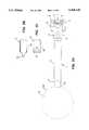
- FIGS. 2A through 2Eshow a two-component apparatus according to the invention, wherein:
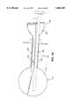
- FIG. 2Ashows the separation component of the two-component apparatus according to the invention.
- FIG. 2Bshows pan of the distal pan of the separation component of the two-component apparatus according to the invention with the main envelope in its evened position.
- FIG. 2Cshows pan of the distal pan of the separation component of the two-component apparatus according to the invention with the main envelope in its inverted position.
- FIG. 2Dshows the insufflation component of the two-component apparatus according to the invention with the toroidal inflatable chamber in its collapsed state.
- FIG. 2Eshows the insufflation component of the two-component apparatus according to the invention with the toroidal inflatable chamber in its expanded state.
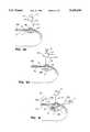
- FIGS. 3A through 3Iare longitudinal cross sections of the abdomen illustrating the method according to the invention of using a two-component apparatus according to the invention to separate the peritoneum from the underlying layer, wherein:
- FIG. 3Ashows an incision made through the abdominal wall, including the properitoneal fat layer, excluding the peritoneum.
- FIG. 3Bshows the distal pan of the separation component of a two-component apparatus according to the invention inserted into the incision.
- the separation componentincludes the main envelope in its collapsed state.
- FIG. 3Cshows the main envelope inflated to its expanded state to separate the peritoneum from the underlying layer.
- FIG. 3Dshows the main envelope returned to its collapsed state.
- FIG. 3Eshows the separation component removed from the incision.
- FIG. 3Fshows the distal pan of the insufflation component of the two-component apparatus according to the invention inserted into the incision.
- FIG. 3Gshows the toroidal inflatable chamber of the insufflation component inflated to its expanded state and the anchor flange slid into contact with the skin of the abdominal wall to provide a gas-tight seal.
- FIG. 3Hshows the working space between the peritoneum and the underlying layer insufflated with a gas passed through the bore of the insufflation component.
- FIG. 3Ishows additional instruments passed through gas-tight trocar sheaths into the insufflated working space to repair the hernia by attaching a mesh patch to the properitoneal fascia.
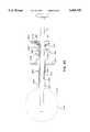
- FIGS. 4A through 4Cshow the main embodiment of the first one-component apparatus according to the invention, wherein:
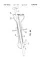
- FIG. 4Ashows the main embodiment of the first one-component apparatus according to the invention with the main envelope in its expanded state.
- FIG. 4Bshows details of the area marked "A" at the distal end of the tube assembly in FIG. 4A.
- FIG. 4Cshows the distal pan of the tube assembly with the toroidal inflatable chamber in its expanded state.
- FIGS. 5A through 5Dshow the alternative embodiment of the first one-component apparatus according to the invent/on, wherein:
- FIG. 5Ashows the alternative embodiment of the first one-component apparatus according to the invention with the main envelope in its expanded state.
- FIG. 5Bshows the elongated main envelope of the alternative embodiment of the first one-component apparatus according to the invention.
- FIG. 5Cshows the distal pan of the tube assembly of the alternative embodiment of the first one-component apparatus according to the invention with the main envelope in its evened state.
- FIG. 5Dshows the distal part of the tube assembly of the alternative embodiment of the first one-component apparatus according to the invention with the main envelope in its inverted state.
- FIGS. 6A through 6Hare longitudinal cross sections of the abdomen illustrating the method according to the invention of using a first-one-component apparatus according to the invention to separate the peritoneum from the underlying layer, wherein:
- FIG. 6Ashows an incision made through the abdominal wall, including the underlying layer, excluding the peritoneum.
- FIG. 6Bshows the distal pan of the tube assembly of a one-component apparatus according to the invention inserted into the incision.
- the tube assemblyincludes the main envelope in its collapsed state.
- FIG. 6Cshows the main envelope inflated to its expanded state to separate the peritoneum from the underlying layer.
- FIG. 6Dshows the main envelope returned to its fully collapsed state.
- FIG. 6Eshows the apparatus advanced into the incision such that the envelope of the toroidal inflatable chamber clears the incision.
- FIG. 6Fshows the toroidal inflatable chamber inflated to its expanded state.
- FIG. 6Gshows the anchor flange slid into contact with the skin of the abdominal wall.
- the anchor flange together with the expanded toroidal inflatable chamberprovides a gas-tight seal.
- FIG. 6Hshows the space between the peritoneum and the underlying layer insufflated with a gas passed through the bore of the apparatus.
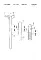
- FIGS. 7A and 7Bshow a second embodiment of a one-component apparatus according to the invention, wherein:
- FIG. 7Ashows the second one-component apparatus according to the invention with the main envelope in its expanded state.
- FIG. 7Bshows the second one-component apparatus according to the invention with the main envelope in its collapsed state.
- FIG. 8Ashows the second one-component apparatus according to the invention with the main envelope in its expanded state and an endoscope passed through the bore of the outer tube into the main inflatable chamber.
- FIG. 8Bshows the second one-component apparatus according to the invention with the main inflatable chamber in its partially expanded state and an endoscope passed through the bore of the inner tube and through the bore of the main envelope.
- FIGS. 9A through 9Fare longitudinal cross sections of the abdomen illustrating the method according to the invention of using a second one-component apparatus according to the invention to separate the peritoneum from the underlying layer, wherein:
- FIG. 9Ashows an incision made through the abdominal wall, including the underlying layer, excluding the peritoneum.
- FIG. 9Bshows the distal part of the tube assembly of a one-component apparatus according to the invention inserted into the incision.
- the tube assemblyincludes the main envelope in its collapsed state.
- FIG. 9Cshows the main envelope inflated to its expanded state to separate the peritoneum from the underlying layer.
- FIG. 9Dshows the main envelope returned to its partially-collapsed state.
- FIG. 9Eshows the anchor flange slid into contact with the skin of the abdominal wall.
- the anchor flange and the partially-collapsed main inflatable chamber togetherprovide a gas-tight seal.
- FIG. 9Fshows the space between the peritoneum and the underlying layer insufflated with a gas passed through the bore of the inner tube of the apparatus.
- FIGS. 10A through 101illustrate the alternative method according to the invention of using any of the apparatus according to the invention to separate the peritoneum from the underlying layer near the groin, with the apparatus inserted through an incision near the umbilicus.
- FIGS. 10A through 10Hare longitudinal cross sections of the abdomen, wherein:
- FIG. 10Ashows an incision made through the abdominal wall, including the underlying layer, excluding the peritoneum.
- FIG. 10Bshows the distal pan of the apparatus according to the invention inserted into the incision.
- the tube assemblyincludes the main envelope in its collapsed state.
- FIG. 10Cshows the main envelope inflated to a partially-expanded state to separate part of the peritoneum from the underlying layer.
- FIG. 10Dshows the main envelope returned to its collapsed state.
- FIG. 10Eshows the apparatus advanced in the direction of the groin to bring the main envelope to the limit of the separated pan of the peritoneum.
- FIG. 10Fshows the main envelope re-inflated to a partially-expanded state to separate an additional part of the peritoneum from the underlying layer.
- FIG. 10Gshows the main envelope advanced to close to the site of the hernia and re-inflated to its fully inflated state to create a working space.
- FIG. 10Hshows the introducer component advanced through the tunnel into the working space, and the toroidal inflatable chamber inflated to form a gas-tight seal with the entrance of the tunnel.
- FIG. 10Iis a plan view of the abdomen showing the insuffiator component in position with its distal end in the working space and its toroidal inflatable chamber forming a gas-tight seal with the entrance of the tunnel. The figure also shows the lesser extent to which the peritoneum is detached in the tunnel compared with in the working space.
- FIG. 1A cross-sectional view of the abdominal wall is shown in FIG. 1.
- the abdominal wallincludes the several layers of tissue shown.
- the peritoneum Pis the innermost layer.
- Underlying the peritoneumare several layers of tissue, including the properitoneal fat layer FL and the properitoneal fascia F.
- the properitoneal fasciais the layer to which the mesh patch is preferably attached in hernia repair.
- the properitoneal fat layerseparates the peritoneum from the properitoneal fascia.
- the properitoneal fat layeris relatively weak, which enables the peritoneum to be separated relatively easily from the fascia. When the peritoneum is separated from the fascia, separation takes place at or in the properitoneal fat layer.
- the properitoneal fat layercan remain attached to the properitoneal fascia, or can come away with the peritoneum. Alternatively, part of the properitoneal fat layer can remain attached to the peritoneum and part of the fat layer can come away attached to the peritoneum. Because of the uncertainty in the point of separation, the layer which is detached will be called the peritoneum, and the layer from which the peritoneum is detached will be called the underlying layer.
- An inguinal herniaoccurs when the contents of the abdominal cavity break through the abdominal wall.
- a herniais repaired by attaching a piece of mesh to the abdominal wall.
- the meshis preferred to attach the mesh to the properitoneal fascia. With the mesh attached to the fascia, the peritoneum covers the mesh and isolates the bowel from the mesh.
- the apparatus and methodsare not restricted to hernia repair.
- the apparatus and methodscan equally well be used in other procedures in which one layer of tissue is separated from another to form a working space between the layers.
- thoracoscopyin patients with pleural adhesions
- pericardioscopyor the introduction of an endoscope into the pericardial cavity, in patients with pericardial adhesions
- retroperitoneal lymph node dissectionin which the peritoneum on the distal aspect of the abdominal cavity is separated from the underlying tissue which includes lymph nodes
- a blood vesselfrom surrounding connective tissue in the course of, for example, a femoropopliteal arterial bypass graft procedure.
- FIGS. 2A through 2CThe two-component form of the apparatus according to the invention is shown in FIGS. 2A through 2C.
- FIG. 2Ashows a partially cut-away view of the separation component 1 of the apparatus.
- the introducer tube 3is a rigid tube having a bore with a circular cross section that can accommodate an endoscope.
- the proximal end of the introducer tubeis fitted with a port 5, in the proximal end 7 of which is mounted a flapper valve 2.
- the shutter 6 of the flapper valveis operated by the button 9.
- the seat 4 of the flapper valveadditionally forms a gas-tight seal with an endoscope or other instrument inserted though the flapper valve into the bore of the introducer tube 3.
- the port 5is also fitted with a valve 11 to which a supply of a suitable inflation fluid can be connected.
- the main envelope 12defines a main inflatable chamber 13.
- the main envelopeis fitted to the distal end 15 of the introducer tube 3.
- the main envelope and main inflatable chamberare shown in their collapsed states.
- the dotted line 12Xindicates the extent of the main envelope when the main inflatable chamber 13 in its expanded state.
- the main envelope 12is preferably formed from an elastomeric material, such as latex, silicone rubber, or polyurethane.
- the main envelopecan also be formed from a thin, inelastic material such as Mylar®, polyethylene, nylon, etc. If an inelastic material is used, it should be suitably packaged to fit inside the bore of the introducer tube 3 when in its collapsed state.
- the preferred elastomeric main envelope 12can be simply attached to the distal end 15 of the introducer tube 3 by stretching the main envelope over the distal end of the introducer tube, as shown in FIG. 2B. The main envelope is then kept in place by friction resulting from the tension caused by stretching.
- a suitable adhesivesuch as an epoxy or cyanoacrylate adhesive, may additionally or alternatively be used. Other means of attaching the main envelope to the inside or the outside of the introducer tube can be used.
- the main envelope 12is inverted into the bore of the introducer tube, as shown in FIG. 2C. Inverting the main envelope into the bore of the introducer tube makes it easier to use the introducer tube to pass the main envelope through an incision and place it adjacent to the peritoneum, as will be described next.
- the first pan of a method according to the invention of using the separation component 1 of a two-component apparatus according to the invention to separate a first layer of tissue from a second layer of tissuewill next be described.
- separating the peritoneum from the properitoneal fascia in the course of repairing a herniawill be described.
- FIGS. 3A through 3Hshow a longitudinal cross section of the lower abdomen.
- An incision about 12-15 mm. longis made in the abdominal wall AW, and is carried through the abdominal wall as far as, and including, the properitoneal fat layer FL
- the distal end 15 of the introducer tube 3 of the separation component 1is then inserted into the incision to bring the distal end into contact with the peritoneum P. Additional gentle pressure detaches the pan of the peritoneum in the immediate vicinity of the incision from the underlying layer, as shown in FIG. 3B.
- FIG. 3Bshows the peritoneum detached from the properitoneal fat layer FL
- the main envelopecannot be seen in these figures because it is inverted within the bore of the introducer tube 3.
- a source of a suitable inflation fluid(not shown) is connected to the valve 11.
- a gaspreferably air
- other gasessuch as carbon dioxide
- a liquidsuch as saline solution, can be used, but liquids are less preferable to gases because they change the optical properties of any endoscope inserted into the main inflatable chamber 13.
- the flow of inflation fluidis turned on., which ejects the main envelope 12 of the main inflatable chamber 13 from the bore of the introducer tube 3.
- the inflation fluidprogressively expands the main envelope 12, and hence the main inflatable chamber 13 defined by the main envelope, into an expanded state.
- the main envelopeexpands between the peritoneum and the properitoneal fascia, and gently and progressively detaches an increasing area of the peritoneum from the underlying layer as it expands.
- the main inflatable chamberis preferably about 4"-6" (100-150 mm) in diameter.
- an endoscope Eis inserted into the flapper valve 2 in the port 5, as shown in FIG. 3C.
- the endoscope Eis passed through the bore of the introducer tube 3 into the main inflatable chamber 13.
- the main envelope 12is sufficiently transparent for the extent of the detachment of the peritoneum to be observed through the endoscope.
- the supply of inflation fluidis turned off.
- the inflation fluidis then vented from the main inflatable chamber, and the main envelope 12 progressively returns to its collapsed state.
- the peritoneumremains detached from the properitoneal fascia, however, as shown in FIG. 3D.
- the separation component 1, including the collapsed main envelope,is then withdrawn from the incision I (FIG. 3E).
- the insufflation component 21 of the two-component apparatusshown in FIG. 2D, will next be described.
- the insufflation component 21comprises an inner tube 35 and an outer tube 37 mounted coaxially, with the outer tube covering the inner tube over most of the length of the inner tube.
- the inner tubeis similar the introducer tube 3 (FIG. 2A), and is a rigid tube having a bore with a circular cross section that can accommodate a 10 mm endoscope.
- the proximal end of the inner tube 35is fitted with a port 25, the proximal end 27 of which has a flapper valve 32.
- the shutter 36 of the flapper valveis operated by the button 29.
- the seat 34 of the flapper valveforms a gas-tight seal with an endoscope (not shown) or an obturator, such as the obturator 33, inserted though the flapper valve into the bore of the inner tube 35.
- the port 25is also fitted with a first valve 31 to which a supply of a suitable insufflation fluid can be connected.
- the distal end 41 of the outer tube 37stops short of the distal end 39 of the inner tube 35.
- the insufflation component 21includes a toroidal inflatable chamber 43.
- the envelope 45 of the toroidal inflatable chamberis a cylindrical piece of a thin elastomeric material, such a latex, silicone rubber, or polyurethane.
- the envelope 45is placed over the distal ends of the inner tube and the outer tube.
- the proximal end 47 of the envelopeis attached to the distal end 41 of the outer tube, and the distal end 49 of the envelope is attached to the distal end 39 of the inner tube 35.
- the bore of the outer tube 37is spaced from the outer surface of the inner tube 35.
- the annular space 51 between the inner tube and the outer tubeinter connects the toroidal inflatable chamber 43 and a second valve 53.
- the second valve 53is connected to a source of a suitable inflation fluid (not shown).
- the toroidal inflatable chamber 45can be inflated using an inflation fluid passing into the toroidal inflatable chamber via the second valve 53 and the annular space 51.
- the toroidal inflatable chamberis shown in its collapsed state in FIG. 2D, and in its expanded state in FIG. 2E.
- the anchor flange 55is slidably mounted on the outer tube 37, and can be locked in a desired position along the length of the outer tube with a simple over-center action locking lever (not shown).
- a simple over-center action locking lever(not shown).
- the anchor flange and the toroidal inflatable chamberin its expanded condition, enable the insuffiator component 21 to form a gas-tight seal to prevent insufflation gas passed through the insufflator component from escaping.
- An obturator 33having a blunt tip 59, is preferably inserted through the flapper valve 32 in the port 25 into the bore of the inner tube 35.
- the tip of the obturatorprojects beyond the distal end of the inner tube to provide the insufflation component 21 with a blunt nose.
- the blunt noseenables the distal end of the insufflation component to be atraumatically inserted into the properitoneal space through the incision I.
- the insufflation componentis advanced through the incision until the proximal end of the cylindrical envelope 45 is in the properitoneal space, clear of the incision, as shown in FIG. 3F.
- a suitable source (not shown) of an inflation fluidis attached to the second valve 53.
- a gassuch as air or carbon dioxide
- a liquidsuch as saline can be used. Since the volume of inflation fluid required to inflate the toroidal inflatable chamber is small, about 15 ml in the preferred embodiment, the inflation fluid can be forced into the toroidal inflatable chamber from a large syringe. Inflation fluid is fed into the toroidal inflatable chamber 43 to expand the toroidal inflatable chamber to its expanded condition, as shown in FIG. 3G.
- the anchor flange 55is then advanced in the direction of the arrow 59 along the outer tube 37 to bring the anchor flange into contact with the skin S of the abdominal wall AW.
- the insufflation component 21is then gripped, and the anchor flange is further advanced slightly. This forces the expanded toroidal inflatable chamber 43 into contact with the underlying layer, and slightly compresses the abdominal wall, including the underlying layer, but excluding the peritoneum P, between the toroidal inflatable chamber and the anchor flange.
- the anchor flangeis locked in position on the outer tube.
- the expanded toroidal inflatable chamberis held against the underlying layer, and forms a gas-tight seal between the insufflation component and the abdominal wall, including the underlying layer, excluding the peritoneum.
- a suitable source (not shown) of an insufflation gasis attached to the first valve 31, and insufflation gas is passed through the bore of the inner tube 35 into the working WS space between the peritoneum P and the underlying layer created by separating by the peritoneum from the underlying layer using the separation component of the apparatus in the first pan of the method described above.
- the pressure of the insufflation gasre-separates the peritoneum from the underlying layer, as shown in FIG. 3H, and provides a working space in which repair of the hernia can be carried out.
- the obturatoris removed from the bore of the inner tube 35.
- the bore of the inner tube 35can then be used to pass instruments, such as the endoscope E, into the working space to perform the repair procedure.
- Insufflation pressureis maintained by the flapper valve 32.
- additional gas-tight trocar sheathsare inserted through the abdominal wall into the working space WS, as shown in FIG. 31.
- An endoscope(not shown) can be passed into the working space through the bore of the inner tube 35, or through one of the additional trocar sleeves for observation. If the properitoneal fat layer FL remains attached to the properitoneal fascia F, it is scraped off the fascia around the site of the hernia so that the patch can be attached directly to the fascia.
- a patch Mpreferably a Dacron® or Teflon® mesh, is shown gripped by the grippers G, and passed through the trocar sleeve TS2 into the working space.
- the patchis manipulated to place it in contact with the properitoneal fascia F over the site of the hernia.
- the patchis attached to the properitoneal fascia by staples inserted using the stapler ST passed through the trocar sleeve TS1 into the working space.
- Suturescan alternatively be used to attach the patch to the properitoneal fascia.
- the first valve 31is operated to release the insufflation gas from the working space.
- the second valve 53is operated to release the inflation fluid from the toroidal inflatable chamber 43.
- the envelope 45 of the toroidal inflatable chamberreturns to its collapsed state, flush with the outer surfaces of the inner tube and the outer tube.
- the insufflating componentis then withdrawn from the incision, and the incision is closed using sutures or clips.
- the pressure of the viscera against the peritoneumreturns the peritoneum into contact with the underlying layer. Over time, the peritoneum reattaches to the underlying layer.
- the separation componentcan be dispensed with, and the insufflation component can be modified to provide the first embodiment of a one component apparatus according to the invention.
- the first one-component apparatusis shown in FIG. 4A.
- the first one-component apparatus 121is similar to the insufflation component just described. Like components will use the same reference numbers with 100 added.
- the first one component apparatuscomprises a tube assembly 160, including an inner tube 135 coaxially mounted inside an outer tube 137.
- the outer tubecovers the inner tube over most of the length of the inner tube.
- the inner tubeis a rigid tube having a bore with a circular cross section that can accommodate an endoscope (not shown).
- the proximal end of the inner tube 135is fitted with a port 125, the proximal end 127 of which includes a flapper valve 132.
- the shutter 136 of the flapper valveis operated by the button 129.
- the seat 134 of the flapper valveforms a gas-tight seal with an endoscope (not shown), or other instrument, inserted though the flapper valve into the bore of the inner tube 135.
- the port 125is also fitted with a first valve 131 to which a supply of a suitable insufflation fluid can be connected.
- the distal end 141 of the outer tube 137extends as far as the distal end 139 of the inner tube 135.
- the tubesare connected together over a distal portion 167 of their lengths (see detail in FIG. 4B).
- a circumferential groove 169is formed in the inner wall of the distal portion 167.
- a groove with a wedge-shaped cross sectionis shown.
- the circumferential groovecan have other cross sections, such as square, or semi-circular.
- the circumferential grooveretains the main envelope 112, which defines the main inflatable chamber 113, in the bore of the inner tube, as will be described in more detail below.
- the envelope 145 of the toroidal inflatable chamber 143covers the distal part of the tube assembly 160.
- the envelope 145is a cylindrical piece of a thin elastomeric material, such a latex, silicone rubber, or polyurethane.
- the proximal end 147 and the distal end 149 of the envelopeare attached to the outer surface 163 of the tube assembly using a circumferential line of adhesive applied at each end of the envelope.
- An epoxy or cyanoacrylate adhesiveis preferably used.
- the outer tube 137is spaced from the inner tube 135 over at least part of its circumference.
- the space 151 between the inner tube and the outer tube, and a radial passage 161 through the wall of the outer tubeinterconnect the toroidal inflatable chamber 143 and the second valve 153.
- the second valve 153is connected to a source of a suitable inflation fluid (not shown).
- the toroidal inflatable chamberis shown in its collapsed state in FIGS. 4A and 4B, and in its expanded state in FIG. 4C.
- the anchor flange 155is slidably mounted on the tube assembly 160, and can be locked in a desired position along the length of the tube assembly with a simple over-center action locking lever (not shown).
- a simple over-center action locking lever(not shown).
- the anchor flange and the toroidal inflatable chamberin its expanded condition, form a gas-tight seal to prevent insufflation gas from escaping.
- the first one-component apparatusalso includes a main envelope 112 detachably attached to the bore of the inner tube 135.
- the main envelopedefines the main inflatable chamber 113.
- the main envelopeis preferably formed of an elastomeric material such as latex, silicone rubber, or polyurethane.
- the main envelopecan also be formed from a thin, inelastic material such as Mylar®, polyethylene, nylon, etc. If an inelastic material is used, it should be suitably packaged to fit inside the bore of the inner tube when in its collapsed state.
- the main envelope 112is formed such that it has a substantially spherical shape when it is in its expanded state, and is also formed with a neck 165.
- the neckhas an outside diameter substantially equal to the diameter of the bore of the inner tube 135.
- the neck 165can be rolled outwards a number of times, as in the neck of a common toy balloon, or the neck can be attached to a suitable O-ring 171, as shown in FIG. 4B.
- the rolled neck, or the O-ring attached to the neckengages with the circumferential groove 169 in the inner wall in the inner tube to attach the main envelope 112 to the inner tube.
- the main envelopeis housed in the bore of the inner tube when the main inflatable chamber is in its collapsed state.
- the rip cord 173is attached to the neck 165 of the main envelope 112, runs proximally up the bore of the inner tube 135, and emerges from the port 125 through the flapper valve 132.
- the pan of the rip cord 173 emerging from the flapper valvecan be gripped and pulled in a proximal direction to release the rolled neck 165 or the O-ring 171 from the circumferential groove 169.
- the entire main envelopecan be pulled proximally through the bore of the inner tube.
- the tube assembly 160Aincludes the inner tube 135A mounted coaxially inside the outer tube 137A, with the proximal and distal ends of the tubes interconnected.
- the space 151A between the inner tube and the outer tubecommunicates with the toroidal inflatable chamber through the radial passage 161A in the wall of the outer tube.
- the space between the inner tube and the outer tubealso communicates with the toroidal chamber inflation valve 153A.
- the bore of the inner tube 135Acommunicates with the port 125A, fitted with the insufflation valve 185.
- the port 125Ais also fitted with a flapper valve 132A, including the flapper valve seat 134A, which maintains gas pressure when the apparatus is used for insufflation.
- the flapper valve seat 134Aalso provides a gas-tight seal around any instrument, such as the endoscope E, passed through the flapper valve.
- the elongated main envelope 112Ais shown in FIG. 5B.
- the main envelopeis an elongated cylinder with a dosed distal end 177.
- the main envelopeis preferably formed from an elastomeric material, such as latex, silicon rubber, or polyurethane.
- Attached to the proximal end of the main envelopeis a manifold 175 which mates with the proximal face 127A of the port 125A.
- the manifold 175is fitted with an O-ring seal 187, which forms a gas-tight seal with any instrument passed through it.
- the manifold 175is also fitted with the main chamber inflation valve 131A to which a supply (not shown) of a suitable inflation fluid can be attached to inflate the main inflatable chamber 112A.
- the elongated main envelope 112Ais passed through the flapper valve 132A into the bore of the inner tube 135A.
- the manifold 175is engaged with the proximal face 127A of the port 125A.
- the distal end 177 of the main envelopeprojects beyond the distal end of the tube assembly 160& as shown in FIG. 5C.
- the distal end of the main envelopeis then inverted into the bore of the inner tube 135A, as shown in FIG. 5D.
- An endoscope, or some other suitable instrument,is inserted through the O-ring seal 187 to seal the manifold before inflation fluid is passed through the main chamber inflation valve 131A to inflate the main inflatable chamber 113A.
- the seal 187can be replaced by an additional flapper valve (not shown) so that the main inflatable chamber can be inflated without the need to use an instrument to seal the manifold.
- the distal end 177 of the main envelope 112Ais ejected from the inner tube 135A.
- the inflation fluidthen progressively expands the main envelope 112A, and hence the main inflatable chamber 113A defined by the main envelope, into an expanded state, as shown in FIG. 5A.
- the pan of the main envelope inside the inner tubeis subject to the same inflation pressure as the distal end 177 of the main envelope, but is constrained by the inner tube and so does not inflate.
- the inflation pressure fluidis vented from the main inflatable chamber 113A, and the main envelope returns to its collapsed state.
- the main envelopeWhen the main envelope is in its collapsed state, it can move freely in the bore of the inner tube 135.
- the main envelopeis removed from the inner tube by disengaging the manifold 175 from the proximal face 127A of the port 125A, and using the manifold 175 to pull the main envelope proximally through the bore of the inner tube.
- Inflation fluid for the toroidal inflatable chamberthe envelope of which 145A is shown in FIG. 5A, is passed through the toroidal chamber inflation valve 153A.
- Insufflation gasis passed through the insufflation valve 185.
- the toroidal inflatable chamber and the anchor flange 155A of the alternative embodiment of the first one-component apparatusare the same as in the main embodiment, and will therefore not be described.
- FIGS. 6A through 6Hshow a longitudinal cross section of the lower abdomen.
- An incision about 12-15 mm. longis made in the abdominal wall AW, and carried through the abdominal wall as far as, and including the properitoneal fat layer FL, as shown in FIG. 6A.
- the distal end 115 of the tube assembly 160 of the one-component apparatus 121is then inserted into the incision to bring the distal end into contact with the peritoneum. Additional gentle pressure detaches the part of the peritoneum in the immediate vicinity of the incision from the underlying layer, as shown in FIG. 6B.
- FIG. 6Bshows the peritoneum detached from the properitoneal fat layer FL.
- the main envelopecannot be seen in these figures because it is inverted within the bore of the tube assembly.
- a source of inflation fluid(not shown) is connected to the valve 131.
- a gaspreferably air
- other gasessuch a carbon dioxide can be used.
- a liquidsuch as saline solution can be used, but liquids are less preferable to gases because they change the optical properties of any endoscope inserted into the main inflatable chamber 113.
- the flow of inflation fluidis turned on, which ejects the main envelope 112 from the bore of the tube assembly 160.
- the inflation fluidprogressively expands the main envelope 112, and hence the main inflatable chamber 113 defined by the main envelope, into an expanded state.
- the main envelopeexpands between the peritoneum P and the properitoneal fat layer FL, and gently and progressively detaches an increasing area of the peritoneum from the underlying layer as it expands.
- the main inflatable chamberis preferably about 4"-6" (100-150 mm) in diameter.
- an endoscope Eis inserted into the flapper valve 132 in the port 125, as shown in FIG. 6C.
- the endoscope Eis passed through the bore of the tube assembly 160 into the main inflatable chamber 113.
- the main envelopeis sufficiently transparent for the extent of the detachment of the peritoneum to be observed using the endoscope.
- the supply of inflation fluidis turned off.
- the inflation fluidis then vented from the main inflatable chamber 113, and the main envelope progressively returns to its collapsed state.
- the peritoneumremains detached from the underlying layer, however, as shown in FIG. 6D.
- the main envelopeis then removed from the bore of the tube assembly 160.
- the tube assemblyis advanced into the incision in the direction of the arrow 162 until the proximal end of the envelope 145 of the toroidal inflatable chamber is in the properitoneal space, clear of the incision, as shown in FIG. 6E.
- a suitable source (not shown) of an inflation fluidis attached to the valve 153.
- a gassuch as air or carbon dioxide
- a liquidsuch as saline can be used. Since the volume of inflation fluid required to inflate the toroidol inflatable chamber is small, about 15 ml in the preferred embodiment, the inflation fluid can be contained in a large syringe. Inflation fluid is fed into the toroidal inflatable chamber 43 to expand the toroidal inflatable chamber to its expanded condition, as shown in FIG. 6F.
- the anchor flange 155is then advanced in the direction of the arrow 159 along the tube assembly 160 to bring the anchor flange into contact with the skin S of the abdominal wall AW.
- the tube assembly 160is then gripped, and the anchor flange is further advanced slightly. This forces the expanded toroidal inflatable chamber 143 into contact with the underlying layer, and slightly compresses the abdominal wall AW, including the underlying layer but excluding the peritoneum P, between the expanded toroidal inflatable chamber and the anchor flange, as shown in FIG. 6G.
- the anchor flangeis locked in position on the tube assembly.
- the expanded toroidal inflatable chamberis held against the underlying layer and forms a gas-tight seal with the abdominal wall, excluding the peritoneum.
- a suitable source (not shown) of an insufflation gasis attached to the first valve 131, and insufflation gas is passed through the bore of the inner tube 135 into the working space WS between the peritoneum P and the underlying layer created by separating the peritoneum from the underlying layer.
- the pressure of the insufflation gasre-separates the peritoneum from the underlying layer, as shown in FIG. 6H, and provides a working space in which repair of the hernia can be carried out.
- the bore of the tube assembly 160can be used to pass instruments, such as the endoscope E, into the working space to perform the repair procedure. When no instrument is inserted into the bore of the tube assembly, insufflation pressure is maintained by the flapper valve.
- additional gas-tight trocar sleeves(not shown) are inserted through the abdominal wall into the working space.
- the same procedure as described above in connection with FIG. 3Iis used to attach a mesh patch to the properitoneal fascia over the site of the hernia.
- the processcan be observed with the aid of an endoscope (not shown) passed through the bore of the tube assembly 160, or through one of the additional trocar sleeves.
- the valve 131is operated to release the insufflation gas from the working space WS.
- the valve 153is operated to release the inflation fluid from the toroidal inflatable chamber 143, which releases compression of the abdominal wall AW, excluding the peritoneum.
- the toroidal inflatable chamberreturns to its collapsed state, with its envelope 145 flush with the outer surface the tube assembly 160.
- the tube assemblyis then withdrawn from the incision, and the incision is closed using sutures or dips.
- the pressure of the viscera against the peritoneumreturns the peritoneum into contact with the underlying layer. Over time, the peritoneum reattaches to the underlying layer.
- FIGS. 7A and 7BA second embodiment of a one-component apparatus is shown in FIGS. 7A and 7B.
- the second one-component apparatus 121is similar to the first one-component apparatus just described.
- the second one-component apparatushas a substantially spherical toroidal main inflatable chamber, that avoids the need to detach and remove the main envelope at the end of the separation process.
- a single toroidal main inflatable chamberprovides the separating function of the main inflatable chamber and the sealing function of the toroidal inflatable chamber of the first one-component apparatus.
- the second one-component apparatuscomprises a tube assembly 260, including an outer tube 237 to which is attached a twin port assembly 224 is attached.
- the port assemblyincludes a first port 226 and a second port 228.
- the first portis provided with a first flapper valve 202, including the flapper valve seat 204.
- the second portis provided with a second flapper valve 206, including the flapper valve seat 208.
- Each flapper valve seatadditionally forms a gas-tight seal with an instrument passed through it.
- the tube assembly 260also includes the inner tube 235.
- the inner tubehas a length that is shorter than the length of the outer tube 237.
- the proximal end 210 of the inner tubeis flexibly attached to the proximal end 222 of the outer tube 237 and to the first port 226.
- the flexible attachmentenables the distal end 214 of the inner tube to move in the direction shown by the arrow 216.
- the first portcommunicates with the bore of the inner tube 235, and the second port communicates with the bore of the outer tube 237.
- the insufflation valve 285communicates with the first port 226, and the bore of the inner tube 235.
- the main chamber inflation valve 231communicates with the second port 228, and the bore of the outer tube 237.
- the main envelope 212defines the main inflatable chamber 213 and comprises a cylindrical piece of an elastomeric material such a latex, silicone rubber, or polyurethane.
- the apparatusis shown with its main envelope in its collapsed state in FIG. 7B, in which the structure of the main envelope can also be seen.
- the main envelopepreferably has a diameter smaller than the outside diameter of the inner tube.
- One end 230 of the main envelopeis attached to the distal end 214 of the inner tube 235 by means of a suitable adhesive, such as an epoxy or cyanoacrylate adhesive.
- the other end 232 of the main envelopeis evened (i.e., turned back on itself to bring the inside surface 234 of the main envelope to the outside) and attached to the distal end 236 of the outer tube using the same type of adhesive.
- the main envelopeis preferably attached to the outer surfaces of the inner tube and the outer tube.
- FIG. 7AThe apparatus is shown with the main envelope 212 in its expanded state in FIG. 7A.
- a suitable source of inflation gasis connected to the valve 231 and flows into the main inflatable chamber through the bore of the outer tube 237.
- the pressure acting on the surface 238 of the main envelope 212causes the main envelope to assume the toroidal shape shown in FIG. 7A to define the toroidal main chamber 213.
- FIGS. 7A and 7Bshow the correspondence between the surfaces 234 and 238 of the main envelope when the main envelope is in its collapsed state (FIG. 7B) and in its expanded state (FIG. 7A).
- the anchor flange 255is slidably mounted on the tube assembly 260, and can be locked in a desired position along the length of the tube assembly.
- the anchor flange 255is similar to the anchor flange 55 (FIG. 2A) and so will not be described further.
- an endoscope Eis shown passed through the second flapper valve 206, the second poll 228, and the bore of the outer tube 237 into the main inflatable chamber 213.
- the flexible mounting of the inner tube 235 in the outer tubeenables the endoscope to displace the inner tube 235 in direction of the arrow 216 to gain access to the main inflatable chamber.
- the endoscopeis inserted through the second port into the main inflatable chamber during the separation phase of using the apparatus to observe the extent of the separation of tissue.
- an endoscope Eis shown passed through the first flapper valve 202, the first port 226, the bore of the inner tube 235, and the bore 234 of the main envelope 212.
- the distal part of the endoscopeemerges from the bore of the main envelope, and can be advanced beyond the main inflatable chamber 213 to observe the site of the hernia more closely.
- the endoscopeis inserted through the first port, the inner tube, and the bore of the main envelope during the insufflation phase of using the apparatus. Instruments other than endoscopes can also be passed to the site of the hernia through the first flapper valve, the first port, the inner tube, and the bore of the main envelope if desired.
- the main envelope 212is shown in the partially collapsed state that it preferably assumes during the insufflation phase of the procedure.
- the partially collapsed main inflatable chamber and the anchor flange 255together provide a gas-tight seal to prevent the leakage of insufflation gas.
- this part of the procedurecan be carried out with the main inflatable chamber in a fully expanded state.
- FIGS. 9A through 9Fshow a longitudinal cross section of the lower abdomen.
- An incision about 12-15 mm longis made in the abdominal wall AW, and carried through the abdominal wall as far as, and including, the properitoneal fat layer FL, as shown in FIG. 9A.
- the distal end 215 of the tube assembly 260 of the second one-component apparatus 221is then inserted into the incision to bring the distal end into contact with the peritoneum P. Additional gentle pressure detaches the pan of the peritoneum in the immediate vicinity of the incision from the underlying layer, as shown in FIG. 9B.
- FIG. 9Bshows the peritoneum detached from the properitoneal fat layer FL
- the main envelopecannot be seen in these figures because it is inverted within the bore of the tube assembly.
- a source of inflation fluid(not shown) is connected to the valve 231.
- a gaspreferably air
- other gasessuch a carbon dioxide can be used.
- a liquidsuch as saline solution can be used, but liquids are less preferable to gases because they change the optical properties of any endoscope inserted into the main inflatable chamber.
- the flow of inflation fluidis turned on, which ejects the main envelope 212 from the bore of the tube assembly 260.
- the Marion fluidprogressively expands the main envelope 212, and hence the main inflatable chamber 213 defined by the main envelope, into an expanded state.
- the main envelopeexpands between the peritoneum P and the properitoneal fat layer FL, and gently and progressively separates an increasing area of the peritoneum from the underlying layer as it expands.
- the main inflatable chamberis preferably about 4"-6" (100-150 mm) in diameter.
- an endoscope Eis inserted into the first flapper valve 202, as shown in FIG. 9C.
- the endoscope Eis passed through the bore of the outer tube 237 into the main inflatable chamber 213.
- the main envelope 212is sufficiently transparent for the extent of the separation of the peritoneum to be observed using the endoscope.
- the supply of inflation fluidis turned off.
- the endoscope Eis removed from the main inflatable chamber 213.
- the valve 231is then opened to allow inflation fluid to vent partially from the main inflatable chamber 213.
- the main envelope 212progressively returns part-way towards its collapsed state, as shown in FIG. 9D. Alternatively, the main envelope may be kept fully expanded.
- the anchor flange 255is then advanced in the direction of the arrow 259 along the tube assembly 260 to bring the anchor flange into contact with the skin S of the abdominal wall AW.
- the tube assembly 260is then gripped, and the anchor flange is further advanced slightly. This forces the main inflatable chamber 213 into contact with the underlying layer, and slightly compresses the abdominal wall, including the underlying layer but excluding the peritoneum, between the main inflatable chamber and the anchor flange, as shown in FIG. 9E.
- the anchor flangeis locked in position on the tube assembly.
- the main inflatable chamberis held against the underlying layer and forms a gas-tight seal with the abdominal wall, excluding the peritoneum.
- a suitable source (not shown) of insufflation gasis attached to the second valve 285, and insufflation gas is passed through the bore of the inner tube 235, and the bore 234 of the main envelope, into the working space WS between the peritoneum P and the underlying layer.
- the pressure of the insufflation gasre-separates the peritoneum from the underlying layer, as shown in FIG. 9F, and provides a working space in which repair of the hernia can be carried out.
- Instrumentssuch as the endoscope E, can be passed through the second flapper valve 206, the bore of the inner tube 235, and the bore 234 of the main envelope, as shown in FIG. 8B, into the working space to perform the repair procedure.
- insufflation pressureis maintained by the second flapper valve.
- additional gas-tight trocar sleevesare inserted through the abdominal wall into the working space.
- the same procedure as described above in connection with FIG. 3Iis used to attach a mesh patch to the properitoneal fascia over the site of the hernia.
- the processcan be observed with the aid of an endoscope (not shown) passed into the working space through the bore of the inner tube 235, or through one of the additional trocar sleeves.
- valve 285is operated to release the insufflation gas from the working space.
- the valve 231is operated to release the inflation fluid from the main inflatable chamber 213, which releases compression from the abdominal wall, excluding the peritoneum.
- the main envelopereturns to its collapsed state inside the bore of the outer tube 237.
- the tube assemblyis then withdrawn from the incision, and the incision is closed using sutures or clips.
- the pressure of the viscera against the peritoneumreturns the peritoneum into contact with the underlying layer. Over time, the peritoneum reattaches to the underlying layer.
- the hernia repair methods described so farshow the incision placed close to the site of the hernia.
- it is preferred to make the incision at or near the umbilicusbecause the boundary between the peritoneum and the properitoneal fat layer can be more directly accessed near the umbilicus.
- the midline location of the umbilicusis devoid of muscle layers that would otherwise need to be traversed to reach the properitoneal fat layer.
- Apparatus of the types described above inserted through an incision at the umbilicuswould require a very large main inflatable chamber to detach the peritoneum from the umbilicus to the groin.
- an apparatus of any one of the types described aboveis used to provide a tunnel from an incision at the umbilicus to the site of the hernia in the groin, and then to provide an insufflated working space at the site of the hernia.
- the main envelopeis partially expanded, collapsed, and advanced towards the site of the hernia. This sequence is repeated to progressively separate the peritoneum from the underlying layer and form the tunnel from the umbilicus to the site of the hernia. Then, at or near the site of the hernia, the main envelope is fully expanded to provide the working space at the site of the hernia. The working space is then insufflated to maintain the separation of the peritoneum from the underlying layer.
- the following methodcan be practiced using the two-component embodiment of the apparatus, or any of the one-component embodiments of the apparatus.
- the methodwill be described using the two-component apparatus.
- An incision about 12-15 mm longis made in the abdominal wall AW, and is carried through the abdominal wall as far as, and including, the properitoneal fat layer FL.
- the incisionis made at the umbilicus U, as shown in FIG. 10A.
- the distal end 15 of the introducer tube 3 of the separation component 1is then inserted into the incision to bring the distal end into contact with the peritoneum P. Additional gentle pressure detaches the pan of the peritoneum in the immediate vicinity of the incision from the underlying layer, as shown in FIG. 10B.
- FIG. 10Bthe peritoneum is shown detached from the properitoneal fat layer FL
- the main envelopecannot be seen in these figures because it is inverted within the bore of the introducer tube 3.
- a source of a suitable inflation fluid(not shown), as previously described, is connected to the valve 11.
- the flow of inflation fluidis turned on, which ejects the main envelope 12 of the main inflatable chamber 13 from the bore of the introducer tube 3.
- the inflation fluidprogressively expands the main envelope 12, and hence the main inflatable chamber 13 defined by the main envelope, into a partially-expanded state, as shown in FIG. 10C.
- the main envelopeexpands between the peritoneum and the properitoneal fat layer FL, and gently and progressively detaches an increasing area of the peritoneum P from the underlying layer near the umbilicus as it expands.
- An endoscope(not shown) can be inserted into the main inflatable chamber 13 through the flapper valve 2 and the bore of the introducer tube 3.
- the endoscopecan be used to observe the extent of the separation of the peritoneum, as described above.
- the supply of inflation fluidis turned off.
- the valve 11is then operated to vent inflation fluid from the main inflatable chamber 13.
- the main envelopeprogressively returns to its collapsed state, as shown in FIG. 10D.
- the peritoneum DP that was separated by the main inflatable chamberremains detached from the underlying layer, however, as shown.
- the main envelopecan be inflated to a fully-expanded state.
- the separation component 1, including the collapsed main envelope 12,is then manipulated in the direction indicated by the arrow 14, and then in the direction indicated by the arrow 16, to advance the distal part 15 of the introducer tube 3 to the limit of the detached part of the peritoneum DP in the direction of the groin, as shown in FIG. 10E.
- An endoscope E inserted through the flapper valve 2 into the bore of the introducer tube 3enables the position of the distal part of the introducer tube relative to the detached part of the peritoneum to be observed.
- the separation component 1is clamped in position, or is gripped, and inflation fluid is once more passed through the valve 11, and the bore of the introducer tube 3 into the main inflatable chamber 13.
- the main envelope 12expands once more, increasing the extent of the detached part of the peritoneum towards the groin, as shown in FIG. 10F.
- the increased extent of the detached part of the peritoneumis indicated by the line DF in the figure. It should be noted that the extent of the detached part of the peritoneum is increased in the direction from the umbilicus to the groin, but not in the direction transverse to this direction.
- the endoscope Eis used to observe the extent of the separation.
- the process of collapsing the main envelope 12, advancing the distal part 15 of the introducer tube to the limit of the detached part of the peritoneum DP, in the direction of the groin, holding the introducer tube in position, and partially re-inflating the main envelope 12,is repeated until the detached part of the peritoneum includes the peritoneum over the site of the hernia.
- This processprovides the tunnel T between the incision at the umbilicus and the site of the hernia. This can be seen in FIG. 10I.
- the main envelopecan be fully re-inflated.
- the main envelope 12When the main envelope is in the vicinity of the site of the hernia H, the main envelope 12 is fully inflated to form a working space WS including the site of the hernia. This is shown in FIG. 10G.
- the working space at the site of the herniais then insufflated.
- inflation fluidis vented from the main inflatable chamber 13 to collapse the main envelope 12, and the separation component 1 is withdrawn from the tunnel T through the incision I.
- the insufflation component 21is introduced into the incision, and advanced through the tunnel until the envelope 45 of the toroidal inflatable chamber 43 lies within the working space WS, dear of the tunnel.
- the toroidal inflatable chamberis inflated, the anchor flange is clamped in position, and insufflation gas is passed into the working space, as shown in FIG. 10H.
- the toroidal inflatable chamberprovides a gas-tight seal with the entrance of the tunnel.
- FIG. 10Ishows a plan view of the abdomen with the insufflator component 21 in place.
- the anchor flangehas been omitted for clarity.
- the toroidal inflatable chamber 43provides a gas-tight seal with the entrance of the tunnel T.
- the extent of the separated peritoneumis indicated by the dotted line DP. It can be seen that the lateral extent of the separated peritoneum is considerably greater in the working space WS than in the tunnel T.
- inflation fluidis vented from the main inflatable chamber to collapse the main envelope, and the main envelope is withdrawn from the working space through the bore of the tube assembly.
- the tube assemblyis partially withdrawn until the envelope of the toroidal inflatable chamber lies within the working space, clear of the entrance to the tunnel.
- the toroidal inflatable chamberis inflated, the anchor flange is clamped in position and insufflation gas is passed into the working space, as already described.
- the toroidal inflatable chamberseals against the entrance from the tunnel into the working space.
- the main envelopeis preferably returned to a partially collapsed state, the tube assembly is partially withdrawn until the main inflatable chamber lies within the working space, adjacent to the entrance of the tunnel.
- the anchor flangeis clamped in position, and insufflation gas is passed into the working space, as already described.
- the partially-collapsed main chamberseals against the entrance from the tunnel into the working space.
- the main envelopeis inflated to a fully expanded state during the separation part of the procedure, the whole of the space is insufflated with a gas-tight seal at the incision, as previously described.
- the herniais then repaired using the procedure described in connection with FIG. 3I.
Landscapes
- Health & Medical Sciences (AREA)
- Surgery (AREA)
- Life Sciences & Earth Sciences (AREA)
- Medical Informatics (AREA)
- Animal Behavior & Ethology (AREA)
- Engineering & Computer Science (AREA)
- Biomedical Technology (AREA)
- Heart & Thoracic Surgery (AREA)
- Veterinary Medicine (AREA)
- Molecular Biology (AREA)
- Nuclear Medicine, Radiotherapy & Molecular Imaging (AREA)
- General Health & Medical Sciences (AREA)
- Public Health (AREA)
- Pathology (AREA)
- Orthopedic Medicine & Surgery (AREA)
- Vascular Medicine (AREA)
- Oral & Maxillofacial Surgery (AREA)
- Surgical Instruments (AREA)
- Endoscopes (AREA)
Abstract
Description
Claims (34)
Priority Applications (1)
| Application Number | Priority Date | Filing Date | Title |
|---|---|---|---|
| US08/111,211US5468248A (en) | 1991-05-29 | 1993-08-24 | Endoscopic inflatable retraction devices for separating layers of tissue |
Applications Claiming Priority (4)
| Application Number | Priority Date | Filing Date | Title |
|---|---|---|---|
| US70678191A | 1991-05-29 | 1991-05-29 | |
| US07/794,590US5309896A (en) | 1991-05-29 | 1991-11-19 | Retraction methods using endoscopic inflatable retraction devices |
| US91171492A | 1992-07-10 | 1992-07-10 | |
| US08/111,211US5468248A (en) | 1991-05-29 | 1993-08-24 | Endoscopic inflatable retraction devices for separating layers of tissue |
Related Parent Applications (1)
| Application Number | Title | Priority Date | Filing Date |
|---|---|---|---|
| US91171492ADivision | 1991-05-29 | 1992-07-10 |
Publications (1)
| Publication Number | Publication Date |
|---|---|
| US5468248Atrue US5468248A (en) | 1995-11-21 |
Family
ID=46248089
Family Applications (1)
| Application Number | Title | Priority Date | Filing Date |
|---|---|---|---|
| US08/111,211Expired - LifetimeUS5468248A (en) | 1991-05-29 | 1993-08-24 | Endoscopic inflatable retraction devices for separating layers of tissue |
Country Status (1)
| Country | Link |
|---|---|
| US (1) | US5468248A (en) |
Cited By (112)
| Publication number | Priority date | Publication date | Assignee | Title |
|---|---|---|---|---|
| US5667479A (en)* | 1994-06-01 | 1997-09-16 | Archimedes Surgical, Inc. | Method for resection of an anatomic structure |
| WO1997037701A1 (en)* | 1996-04-11 | 1997-10-16 | General Surgical Innovations, Inc. | Extraluminal balloon dissection |
| US5678572A (en)* | 1995-01-12 | 1997-10-21 | Shaw; Dein | Cavity expanding device for laparoscopic surgery |
| US5681341A (en)* | 1995-03-14 | 1997-10-28 | Origin Medsystems, Inc. | Flexible lifting apparatus |
| US5720762A (en)* | 1996-06-24 | 1998-02-24 | Bass; Lawrence S. | Device and method for surgical flap dissection |
| US5816257A (en)* | 1995-12-20 | 1998-10-06 | Origin Medsystems, Inc. | Gasless retroperitoneal surgical procedure |
| US5954713A (en)* | 1996-07-12 | 1999-09-21 | Newman; Fredric A. | Endarterectomy surgical instruments and procedure |
| US6007483A (en)* | 1994-06-01 | 1999-12-28 | Archimedes Surgical, Inc. | Surgical method for developing an anatomic structure |
| US6015421A (en)* | 1997-05-15 | 2000-01-18 | General Surgical Innovations, Inc. | Apparatus and method for developing an anatomic space for laparoscopic procedures |
| US6238373B1 (en)* | 1995-05-19 | 2001-05-29 | General Electric Innovations, Inc. | Screw-type skin seal with inflatable membrane |
| US6264604B1 (en) | 1992-06-02 | 2001-07-24 | General Surgical Innovations, Inc. | Apparatus and method for developing an anatomic space for laparoscopic procedures with laparoscopic visualization |
| US6277094B1 (en) | 1999-04-28 | 2001-08-21 | Medtronic, Inc. | Apparatus and method for dilating ligaments and tissue by the alternating insertion of expandable tubes |
| US6361543B1 (en) | 1991-05-29 | 2002-03-26 | Sherwood Services Ag | Inflatable devices for separating layers of tissue, and methods of using |
| US6364892B1 (en) | 1992-06-02 | 2002-04-02 | General Surgical Innovations, Inc. | Ballon dissector with improved visualization |
| US6432121B1 (en) | 1992-06-02 | 2002-08-13 | General Surgical Innovations, Inc. | Apparatus and method for guiding placement of a minimally invasive surgical instrument |
| US6517530B1 (en) | 1996-11-08 | 2003-02-11 | Leiv Eiriksson Nyfotek As | Probe device |
| US6562056B2 (en) | 1992-06-02 | 2003-05-13 | General Surgical Innovations, Inc. | Balloon device for use in surgery and method of use |
| WO2004096295A2 (en) | 2003-04-25 | 2004-11-11 | Tyco Healthcare Group Lp | Surgical access apparatus |
| US6866676B2 (en) | 1992-06-02 | 2005-03-15 | General Surgical Innovations, Inc. | Apparatus and method for dissecting tissue layers |
| US20050124856A1 (en)* | 2003-12-05 | 2005-06-09 | Tetsuya Fujikura | Insertion assisting tool for endoscope |
| US6953467B2 (en) | 1992-06-02 | 2005-10-11 | General Surgical Innovations, Inc. | Apparatus and method for developing an anatomic space for laparoscopic hernia repair and patch for use therewith |
| US20070213584A1 (en)* | 2006-03-10 | 2007-09-13 | Kim Daniel H | Percutaneous access and visualization of the spine |
| US20070239108A1 (en)* | 2006-03-13 | 2007-10-11 | Applied Medical Resources Corporation | Balloon trocar |
| US7300448B2 (en) | 2002-10-04 | 2007-11-27 | Tyco Healthcare Group Lp | Balloon dissector with cannula |
| US20080015598A1 (en)* | 2006-07-11 | 2008-01-17 | Megan Prommersberger | Novel skin staples |
| US20080097506A1 (en)* | 2002-10-04 | 2008-04-24 | Tyco Healthcare Group Lp | Balloon dissector with cannula |
| EP2050405A2 (en) | 2007-10-17 | 2009-04-22 | Tyco Healthcare Group LP | Access port using shape memory anchor |
| EP2050406A2 (en) | 2007-10-17 | 2009-04-22 | Tyco Healthcare Group LP | Access port using shape altering anchor |
| EP2050404A1 (en) | 2007-10-17 | 2009-04-22 | Tyco Healthcare Group LP | Anchoring Cannula |
| US20090137984A1 (en)* | 2007-11-26 | 2009-05-28 | Ethicon Endo-Surgery, Inc. | Tissue retractors |
| US20090192352A1 (en)* | 2008-01-24 | 2009-07-30 | P Regadas F Sergio | Operating Anoscope For Transanal Endoscopic Microsurgery |
| US20100010530A1 (en)* | 2006-07-14 | 2010-01-14 | Ams Research Corporation | Balloon Dilation for Implantable Prosthesis |
| USD614297S1 (en)* | 2003-10-06 | 2010-04-20 | Tyco Healthcare Group Lp | Surgical instrument |
| US7744617B2 (en)* | 1991-05-29 | 2010-06-29 | Covidien Ag | Method and inflatable chamber apparatus for separating layers of tissue |
| US20100204729A1 (en)* | 2008-09-11 | 2010-08-12 | Ahmad Robert Hadba | Tapered Looped Suture |
| US20100204730A1 (en)* | 2008-10-09 | 2010-08-12 | Nicholas Maiorino | Knotted Suture End Effector |
| US7867163B2 (en) | 1998-06-22 | 2011-01-11 | Maquet Cardiovascular Llc | Instrument and method for remotely manipulating a tissue structure |
| US7938842B1 (en) | 1998-08-12 | 2011-05-10 | Maquet Cardiovascular Llc | Tissue dissector apparatus |
| US20110144447A1 (en)* | 2009-12-11 | 2011-06-16 | Ethicon Endo-Surgery, Inc. | Methods and devices for providing access through tissue to a surgical site |
| US20110144449A1 (en)* | 2009-12-11 | 2011-06-16 | Ethicon Endo-Surgery, Inc. | Methods and devices for providing access through tissue to a surgical site |
| US20110144590A1 (en)* | 2009-12-11 | 2011-06-16 | Ethicon Endo-Surgery, Inc. | Methods and devices for providing access through tissue to a surgical site |
| US20110144437A1 (en)* | 2009-12-11 | 2011-06-16 | Ethicon Endo-Surgery, Inc. | Methods and devices for providing surgical access through tissue to a surgical site |
| US20110144444A1 (en)* | 2009-12-11 | 2011-06-16 | Ethicon Endo-Surgery, Inc. | Methods and devices for providing access through tissue to a surgical site |
| US7963975B2 (en) | 2003-05-08 | 2011-06-21 | Tyco Healthcare Group Lp | Balloon dissector with balloon tip cannula |
| US7967835B2 (en) | 2003-05-05 | 2011-06-28 | Tyco Healthcare Group Lp | Apparatus for use in fascial cleft surgery for opening an anatomic space |
| US7972265B1 (en) | 1998-06-22 | 2011-07-05 | Maquet Cardiovascular, Llc | Device and method for remote vessel ligation |
| US7981133B2 (en) | 1995-07-13 | 2011-07-19 | Maquet Cardiovascular, Llc | Tissue dissection method |
| US8016755B2 (en) | 2000-10-19 | 2011-09-13 | Applied Medical Resources Corporation | Surgical access apparatus and method |
| US8025640B2 (en) | 2008-06-27 | 2011-09-27 | Tyco Healthcare Group Lp | Pressurized surgical valve |
| US8109873B2 (en) | 2007-05-11 | 2012-02-07 | Applied Medical Resources Corporation | Surgical retractor with gel pad |
| US8157835B2 (en) | 2001-08-14 | 2012-04-17 | Applied Medical Resouces Corporation | Access sealing apparatus and method |
| US8187177B2 (en) | 2003-09-17 | 2012-05-29 | Applied Medical Resources Corporation | Surgical instrument access device |
| US8206291B2 (en) | 2009-03-27 | 2012-06-26 | Tyco Healthcare Group Lp | Portal device |
| US8226552B2 (en) | 2007-05-11 | 2012-07-24 | Applied Medical Resources Corporation | Surgical retractor |
| US8235054B2 (en) | 2002-06-05 | 2012-08-07 | Applied Medical Resources Corporation | Wound retractor |
| US8241210B2 (en) | 1998-06-22 | 2012-08-14 | Maquet Cardiovascular Llc | Vessel retractor |
| US8262568B2 (en) | 2008-10-13 | 2012-09-11 | Applied Medical Resources Corporation | Single port access system |
| US8267858B2 (en) | 2005-10-14 | 2012-09-18 | Applied Medical Resources Corporation | Wound retractor with gel cap |
| US8287503B2 (en) | 2006-03-13 | 2012-10-16 | Applied Medical Resources Corporation | Balloon trocar |
| US8343047B2 (en) | 2008-01-22 | 2013-01-01 | Applied Medical Resources Corporation | Surgical instrument access device |
| US8348973B2 (en) | 2006-09-06 | 2013-01-08 | Covidien Lp | Bioactive substance in a barbed suture |
| US8388526B2 (en) | 2001-10-20 | 2013-03-05 | Applied Medical Resources Corporation | Wound retraction apparatus and method |
| US8454653B2 (en) | 2008-02-20 | 2013-06-04 | Covidien Lp | Compound barb medical device and method |
| US8465515B2 (en) | 2007-08-29 | 2013-06-18 | Ethicon Endo-Surgery, Inc. | Tissue retractors |
| US8517931B2 (en) | 2007-11-26 | 2013-08-27 | Ethicon Endo-Surgery, Inc. | Tissue retractors |
| US8703034B2 (en) | 2001-08-14 | 2014-04-22 | Applied Medical Resources Corporation | Method of making a tack-free gel |
| US8758236B2 (en) | 2011-05-10 | 2014-06-24 | Applied Medical Resources Corporation | Wound retractor |
| CN103987306A (en)* | 2011-12-09 | 2014-08-13 | 奥林巴斯株式会社 | Pericardial-liquid level control system |
| US8888692B1 (en) | 2011-08-26 | 2014-11-18 | Applied Medical Resources Corporation | Trocar cannula assembly and method of manufacture |
| US8888810B2 (en) | 2008-02-20 | 2014-11-18 | Covidien Lp | Compound barb medical device and method |
| US8932214B2 (en) | 2003-02-25 | 2015-01-13 | Applied Medical Resources Corporation | Surgical access system |
| US9289115B2 (en) | 2010-10-01 | 2016-03-22 | Applied Medical Resources Corporation | Natural orifice surgery system |
| US9289200B2 (en) | 2010-10-01 | 2016-03-22 | Applied Medical Resources Corporation | Natural orifice surgery system |
| US9522265B2 (en) | 2013-03-15 | 2016-12-20 | Applied Medical Resources Corporation | Trocar cannula assembly with low profile insertion configuration and method of manufacture |
| US9642608B2 (en) | 2014-07-18 | 2017-05-09 | Applied Medical Resources Corporation | Gels having permanent tack free coatings and method of manufacture |
| CN107049381A (en)* | 2017-06-03 | 2017-08-18 | 成都五义医疗科技有限公司 | A sleeve assembly containing a mobile inflatable air bag |
| US9949730B2 (en) | 2014-11-25 | 2018-04-24 | Applied Medical Resources Corporation | Circumferential wound retraction with support and guidance structures |
| US10070853B2 (en) | 2013-08-14 | 2018-09-11 | Covidien Lp | Expandable balloon desufflation assembly |
| US10166376B2 (en) | 2013-06-11 | 2019-01-01 | Covidien Lp | Restricted expansion dissector |
| US10172641B2 (en) | 2014-08-15 | 2019-01-08 | Applied Medical Resources Corporation | Natural orifice surgery system |
| US10299770B2 (en) | 2006-06-01 | 2019-05-28 | Maquet Cardiovascular Llc | Endoscopic vessel harvesting system components |
| US10368908B2 (en) | 2015-09-15 | 2019-08-06 | Applied Medical Resources Corporation | Surgical robotic access system |
| US10507012B2 (en) | 2000-11-17 | 2019-12-17 | Maquet Cardiovascular Llc | Vein harvesting system and method |
| US10575840B2 (en) | 2015-10-07 | 2020-03-03 | Applied Medical Resources Corporation | Wound retractor with multi-segment outer ring |
| US10674896B2 (en) | 2016-09-12 | 2020-06-09 | Applied Medical Resources Corporation | Surgical robotic access system for irregularly shaped robotic actuators and associated robotic surgical instruments |
| US11369400B2 (en) | 2019-03-20 | 2022-06-28 | Covidien Lp | Balloon dissector |
| US11376037B2 (en) | 2020-05-08 | 2022-07-05 | Covidien Lp | Surgical access device including dual lumen cannula for anchor inflation and deflation |
| US11432846B2 (en) | 2020-05-05 | 2022-09-06 | Covidien Lp | Surgical access device including alternating cutout fluid flow pathway for anchor inflation and deflation |
| US11439430B2 (en) | 2020-05-11 | 2022-09-13 | Covidien Lp | Surgical access device with air release mechanism |
| US11471189B2 (en) | 2020-10-29 | 2022-10-18 | Covidien Lp | Surgical access device with fixation mechanism and illumination mechanism |
| US11471142B2 (en) | 2013-03-15 | 2022-10-18 | Applied Medical Resources Corporation | Mechanical gel surgical access device |
| US11484337B2 (en) | 2020-02-06 | 2022-11-01 | Covidien Lp | Surgical access device including anchor with rachet mechanism |
| US11547441B2 (en) | 2020-02-20 | 2023-01-10 | Covidien Lp | Retention anchor for surgical access devices |
| US11564708B2 (en) | 2020-06-15 | 2023-01-31 | Covidien Lp | Cannula assembly including an adjustable elongate shaft assembly |
| US11583315B2 (en) | 2020-11-09 | 2023-02-21 | Covidien Lp | Surgical access device including variable length cannula |
| US11672563B2 (en) | 2020-02-07 | 2023-06-13 | Covidien Lp | Surgical access device with rotatably actuated fixation mechanism |
| US11717322B2 (en) | 2020-08-17 | 2023-08-08 | Covidien Lp | Flexible cannula having selective rigidity |
| US11751906B2 (en) | 2020-10-29 | 2023-09-12 | Covidien Lp | Adapter for use with surgical access device for evacuation of smoke |
| US11751907B2 (en) | 2021-04-13 | 2023-09-12 | Covidien Lp | Surgical access device with self-inflating balloon |
| US11786233B2 (en) | 2020-03-27 | 2023-10-17 | Covidien Lp | Retention anchor with suture tie down for surgical access devices |
| US11839404B2 (en) | 2020-07-28 | 2023-12-12 | Covidien Lp | Surgical access assembly having pre-filled air chamber |
| US11844549B2 (en) | 2020-10-15 | 2023-12-19 | Covidien Lp | Surgical access device including a universal fluid flow valve |
| US11849969B2 (en) | 2020-12-04 | 2023-12-26 | Covidien Lp | Cannula with smoke evacuation housing |
| US11864761B2 (en) | 2021-09-14 | 2024-01-09 | Covidien Lp | Surgical instrument with illumination mechanism |
| US11896263B2 (en) | 2020-05-11 | 2024-02-13 | Covidien Lp | Surgical access device with fixation mechanism |
| US11944348B2 (en) | 2021-04-07 | 2024-04-02 | Covidien Lp | Surgical access device including an anchor having a suture retention mechanism |
| US12059176B2 (en) | 2020-10-05 | 2024-08-13 | Covidien Lp | Surgical access device with differential pressure induced fluid evacuation |
| US12121689B2 (en) | 2021-05-03 | 2024-10-22 | Covidien Lp | Surgical access device having a hollow anchor |
| US12137934B2 (en) | 2020-11-23 | 2024-11-12 | Covidien Lp | Surgical access device with fixation mechanism |
| US12251130B2 (en) | 2021-05-03 | 2025-03-18 | Covidien Lp | Surgical access device having a balloon and methods for manufacturing the same |
| US12268414B2 (en) | 2020-02-26 | 2025-04-08 | Covidien Lp | Retention anchor for surgical access devices |
| US12383303B2 (en) | 2020-11-10 | 2025-08-12 | Covidien Lp | Surgical access device having plural zero closure valves |
Citations (41)
| Publication number | Priority date | Publication date | Assignee | Title |
|---|---|---|---|---|
| US3774596A (en)* | 1971-06-29 | 1973-11-27 | G Cook | Compliable cavity speculum |
| US3782370A (en)* | 1972-07-12 | 1974-01-01 | B Mcdonald | Surgical retractor |
| US3831587A (en)* | 1973-02-08 | 1974-08-27 | Mc Anally R | Multipurpose vaginal and cervical device |
| US3863639A (en)* | 1974-04-04 | 1975-02-04 | Richard N Kleaveland | Disposable visceral retainer |
| US4083369A (en)* | 1976-07-02 | 1978-04-11 | Manfred Sinnreich | Surgical instruments |
| DE2847633A1 (en)* | 1977-11-04 | 1979-05-10 | Olympus Optical Co | Gallstone removal balloon catheter - is introduced through endoscope, with balloon mounted on ends of flexible telescopic tubes |
| EP0010650A1 (en)* | 1978-10-10 | 1980-05-14 | BioNexus, Inc. | Instrument for dispensing material into the Fallopian tubes |
| US4240433A (en)* | 1977-07-22 | 1980-12-23 | Bordow Richard A | Fluid aspiration device and technique for reducing the risk of complications |
| SU797668A1 (en)* | 1978-06-13 | 1981-01-23 | Петрозаводский Государственныйуниверситет Им. O.B.Куусинена | Device for limiting surgery field on small pelvis |
| AU516114B2 (en)* | 1977-03-29 | 1981-05-21 | Frank Baskind Allen | Apparatus for obtaining oytological specimens |
| FR2474304A1 (en)* | 1979-12-13 | 1981-07-31 | Air Foundation | Instrument for pneumatic removal of live tissue e.g. tumour - has hollow handle and shaft with articulated tip directing pressurised fluid at tissue |
| GB2071502A (en)* | 1980-03-14 | 1981-09-23 | Nat Res Dev | Surgical retractors |
| US4291687A (en)* | 1978-03-02 | 1981-09-29 | Manfred Sinnreich | Inflatable packing for surgical use having auxiliary intestinal supporting member |
| US4430076A (en)* | 1982-02-04 | 1984-02-07 | Harris James H | Combined uterine injector and manipulative device |
| US4447227A (en)* | 1982-06-09 | 1984-05-08 | Endoscopy Surgical Systems, Inc. | Multi-purpose medical devices |
| US4598699A (en)* | 1985-06-10 | 1986-07-08 | Garren Lloyd R | Endoscopic instrument for removing stomach insert |
| EP0246086A2 (en)* | 1986-05-14 | 1987-11-19 | Aldo Sergio Kleiman | A procedure for carrying out a surgical operation and a retracting laparoscope for separating organs in surgery |
| EP0251976A2 (en)* | 1986-06-05 | 1988-01-07 | Fogarty, Thomas J. | Shear force gauge and method and apparatus for limiting embolectomy shear force |
| EP0275230A2 (en)* | 1987-01-15 | 1988-07-20 | FOGARTY, Thomas J. | Catheter with corkscrew-like balloon |
| US4775371A (en)* | 1986-09-02 | 1988-10-04 | Advanced Cardiovascular Systems, Inc. | Stiffened dilatation catheter and method of manufacture |
| US4779611A (en)* | 1987-02-24 | 1988-10-25 | Grooters Ronald K | Disposable surgical scope guide |
| FR2646088A1 (en)* | 1989-04-19 | 1990-10-26 | Ruiz Razura Amado | INFLATABLE ENVELOPE FOR ELONGATION OF BIOLOGICAL TISSUES |
| US4984564A (en)* | 1989-09-27 | 1991-01-15 | Frank Yuen | Surgical retractor device |
| US5002557A (en)* | 1989-04-06 | 1991-03-26 | Hasson Harrith M | Laparoscopic cannula |
| US5007898A (en)* | 1988-06-02 | 1991-04-16 | Advanced Surgical Intervention, Inc. | Balloon dilatation catheter |
| DE9104383U1 (en)* | 1991-04-10 | 1991-06-06 | Wisap Gesellschaft für wissenschaftlichen Apparatebau mbH, 8029 Sauerlach | Abdominal cavity expander |
| US5082005A (en)* | 1990-12-18 | 1992-01-21 | New England Deaconess Hospital | Surgical access device |
| EP0480653A1 (en)* | 1990-10-09 | 1992-04-15 | VANCE PRODUCTS INCORPORATED d/b/a COOK UROLOGICAL INCORPORATED | Surgical access sheath |
| US5122122A (en)* | 1989-11-22 | 1992-06-16 | Dexide, Incorporated | Locking trocar sleeve |
| US5122155A (en)* | 1990-10-11 | 1992-06-16 | Eberbach Mark A | Hernia repair apparatus and method of use |
| US5141515A (en)* | 1990-10-11 | 1992-08-25 | Eberbach Mark A | Apparatus and methods for repairing hernias |
| US5147316A (en)* | 1990-11-19 | 1992-09-15 | Castillenti Thomas A | Laparoscopic trocar with self-locking port sleeve |
| US5176697A (en)* | 1989-04-06 | 1993-01-05 | Hasson Harrith M | Laparoscopic cannula |
| US5176692A (en)* | 1991-12-09 | 1993-01-05 | Wilk Peter J | Method and surgical instrument for repairing hernia |
| US5188630A (en)* | 1991-03-25 | 1993-02-23 | Christoudias George C | Christoudias endospongestick probe |
| US5195507A (en)* | 1990-11-06 | 1993-03-23 | Ethicon, Inc. | Endoscopic surgical instrument for displacing tissue or organs |
| US5201742A (en)* | 1991-04-16 | 1993-04-13 | Hasson Harrith M | Support jig for a surgical instrument |
| FR2688695A1 (en)* | 1992-03-20 | 1993-09-24 | Bogdanoff Joseph | Medical mattress |
| US5250025A (en)* | 1990-08-15 | 1993-10-05 | Intramed Laboratories | Percutaneous access catheter and method of use |
| US5269753A (en)* | 1992-07-14 | 1993-12-14 | Wilk Peter J | Method for use in laparoscopic hernia repair |
| US5359995A (en)* | 1991-02-04 | 1994-11-01 | Sewell Jr Frank | Method of using an inflatable laparoscopic retractor |
- 1993
- 1993-08-24USUS08/111,211patent/US5468248A/ennot_activeExpired - Lifetime
Patent Citations (42)
| Publication number | Priority date | Publication date | Assignee | Title |
|---|---|---|---|---|
| US3774596A (en)* | 1971-06-29 | 1973-11-27 | G Cook | Compliable cavity speculum |
| US3782370A (en)* | 1972-07-12 | 1974-01-01 | B Mcdonald | Surgical retractor |
| US3831587A (en)* | 1973-02-08 | 1974-08-27 | Mc Anally R | Multipurpose vaginal and cervical device |
| US3863639A (en)* | 1974-04-04 | 1975-02-04 | Richard N Kleaveland | Disposable visceral retainer |
| US4083369A (en)* | 1976-07-02 | 1978-04-11 | Manfred Sinnreich | Surgical instruments |
| AU516114B2 (en)* | 1977-03-29 | 1981-05-21 | Frank Baskind Allen | Apparatus for obtaining oytological specimens |
| US4240433A (en)* | 1977-07-22 | 1980-12-23 | Bordow Richard A | Fluid aspiration device and technique for reducing the risk of complications |
| DE2847633A1 (en)* | 1977-11-04 | 1979-05-10 | Olympus Optical Co | Gallstone removal balloon catheter - is introduced through endoscope, with balloon mounted on ends of flexible telescopic tubes |
| US4291687A (en)* | 1978-03-02 | 1981-09-29 | Manfred Sinnreich | Inflatable packing for surgical use having auxiliary intestinal supporting member |
| SU797668A1 (en)* | 1978-06-13 | 1981-01-23 | Петрозаводский Государственныйуниверситет Им. O.B.Куусинена | Device for limiting surgery field on small pelvis |
| EP0010650A1 (en)* | 1978-10-10 | 1980-05-14 | BioNexus, Inc. | Instrument for dispensing material into the Fallopian tubes |
| FR2474304A1 (en)* | 1979-12-13 | 1981-07-31 | Air Foundation | Instrument for pneumatic removal of live tissue e.g. tumour - has hollow handle and shaft with articulated tip directing pressurised fluid at tissue |
| GB2071502A (en)* | 1980-03-14 | 1981-09-23 | Nat Res Dev | Surgical retractors |
| US4430076A (en)* | 1982-02-04 | 1984-02-07 | Harris James H | Combined uterine injector and manipulative device |
| US4447227A (en)* | 1982-06-09 | 1984-05-08 | Endoscopy Surgical Systems, Inc. | Multi-purpose medical devices |
| US4598699A (en)* | 1985-06-10 | 1986-07-08 | Garren Lloyd R | Endoscopic instrument for removing stomach insert |
| EP0246086A2 (en)* | 1986-05-14 | 1987-11-19 | Aldo Sergio Kleiman | A procedure for carrying out a surgical operation and a retracting laparoscope for separating organs in surgery |
| EP0251976A2 (en)* | 1986-06-05 | 1988-01-07 | Fogarty, Thomas J. | Shear force gauge and method and apparatus for limiting embolectomy shear force |
| US4775371A (en)* | 1986-09-02 | 1988-10-04 | Advanced Cardiovascular Systems, Inc. | Stiffened dilatation catheter and method of manufacture |
| EP0275230A2 (en)* | 1987-01-15 | 1988-07-20 | FOGARTY, Thomas J. | Catheter with corkscrew-like balloon |
| US4779611A (en)* | 1987-02-24 | 1988-10-25 | Grooters Ronald K | Disposable surgical scope guide |
| US5007898A (en)* | 1988-06-02 | 1991-04-16 | Advanced Surgical Intervention, Inc. | Balloon dilatation catheter |
| US5002557A (en)* | 1989-04-06 | 1991-03-26 | Hasson Harrith M | Laparoscopic cannula |
| US5176697A (en)* | 1989-04-06 | 1993-01-05 | Hasson Harrith M | Laparoscopic cannula |
| FR2646088A1 (en)* | 1989-04-19 | 1990-10-26 | Ruiz Razura Amado | INFLATABLE ENVELOPE FOR ELONGATION OF BIOLOGICAL TISSUES |
| US4984564A (en)* | 1989-09-27 | 1991-01-15 | Frank Yuen | Surgical retractor device |
| US5122122A (en)* | 1989-11-22 | 1992-06-16 | Dexide, Incorporated | Locking trocar sleeve |
| US5250025A (en)* | 1990-08-15 | 1993-10-05 | Intramed Laboratories | Percutaneous access catheter and method of use |
| EP0480653A1 (en)* | 1990-10-09 | 1992-04-15 | VANCE PRODUCTS INCORPORATED d/b/a COOK UROLOGICAL INCORPORATED | Surgical access sheath |
| US5122155A (en)* | 1990-10-11 | 1992-06-16 | Eberbach Mark A | Hernia repair apparatus and method of use |
| US5141515A (en)* | 1990-10-11 | 1992-08-25 | Eberbach Mark A | Apparatus and methods for repairing hernias |
| US5195507A (en)* | 1990-11-06 | 1993-03-23 | Ethicon, Inc. | Endoscopic surgical instrument for displacing tissue or organs |
| US5147316A (en)* | 1990-11-19 | 1992-09-15 | Castillenti Thomas A | Laparoscopic trocar with self-locking port sleeve |
| US5082005A (en)* | 1990-12-18 | 1992-01-21 | New England Deaconess Hospital | Surgical access device |
| US5359995A (en)* | 1991-02-04 | 1994-11-01 | Sewell Jr Frank | Method of using an inflatable laparoscopic retractor |
| US5188630A (en)* | 1991-03-25 | 1993-02-23 | Christoudias George C | Christoudias endospongestick probe |
| DE9104383U1 (en)* | 1991-04-10 | 1991-06-06 | Wisap Gesellschaft für wissenschaftlichen Apparatebau mbH, 8029 Sauerlach | Abdominal cavity expander |
| US5201742A (en)* | 1991-04-16 | 1993-04-13 | Hasson Harrith M | Support jig for a surgical instrument |
| US5176692A (en)* | 1991-12-09 | 1993-01-05 | Wilk Peter J | Method and surgical instrument for repairing hernia |
| WO1993011824A1 (en)* | 1991-12-09 | 1993-06-24 | Cinberg James Z | Method and surgical instrument for repairing internal organ |
| FR2688695A1 (en)* | 1992-03-20 | 1993-09-24 | Bogdanoff Joseph | Medical mattress |
| US5269753A (en)* | 1992-07-14 | 1993-12-14 | Wilk Peter J | Method for use in laparoscopic hernia repair |
Non-Patent Citations (2)
| Title |
|---|
| M. M. Gazayerli, "the Gazayerli Endoscopic Retractor, Model 1;" Surgical Laparoscopy & Endoscopy, vol. 1, No. 2, pp. 98-100 Raven Press, New York, Jun. 1991. |
| M. M. Gazayerli, the Gazayerli Endoscopic Retractor, Model 1; Surgical Laparoscopy & Endoscopy, vol. 1, No. 2, pp. 98 100 Raven Press, New York, Jun. 1991.* |
Cited By (224)
| Publication number | Priority date | Publication date | Assignee | Title |
|---|---|---|---|---|
| US7744617B2 (en)* | 1991-05-29 | 2010-06-29 | Covidien Ag | Method and inflatable chamber apparatus for separating layers of tissue |
| US6361543B1 (en) | 1991-05-29 | 2002-03-26 | Sherwood Services Ag | Inflatable devices for separating layers of tissue, and methods of using |
| US6953467B2 (en) | 1992-06-02 | 2005-10-11 | General Surgical Innovations, Inc. | Apparatus and method for developing an anatomic space for laparoscopic hernia repair and patch for use therewith |
| US8282665B2 (en) | 1992-06-02 | 2012-10-09 | Tyco Healthcare Group Lp | Apparatus and method for dissecting tissue layers |
| US7297153B2 (en) | 1992-06-02 | 2007-11-20 | General Surgical Innovations, Inc. | Apparatus and method for developing an anatomic space for laparoscopic hernia repair and patch for use therewith |
| US7179272B2 (en) | 1992-06-02 | 2007-02-20 | General Surgical Innovations, Inc. | Apparatus and method for dissecting tissue layers |
| US6264604B1 (en) | 1992-06-02 | 2001-07-24 | General Surgical Innovations, Inc. | Apparatus and method for developing an anatomic space for laparoscopic procedures with laparoscopic visualization |
| US6866676B2 (en) | 1992-06-02 | 2005-03-15 | General Surgical Innovations, Inc. | Apparatus and method for dissecting tissue layers |
| US6562056B2 (en) | 1992-06-02 | 2003-05-13 | General Surgical Innovations, Inc. | Balloon device for use in surgery and method of use |
| US6432121B1 (en) | 1992-06-02 | 2002-08-13 | General Surgical Innovations, Inc. | Apparatus and method for guiding placement of a minimally invasive surgical instrument |
| US6364892B1 (en) | 1992-06-02 | 2002-04-02 | General Surgical Innovations, Inc. | Ballon dissector with improved visualization |
| US8187296B2 (en) | 1992-06-02 | 2012-05-29 | Tyco Healthcare Group Lp | Apparatus and method for developing an anatomic space for laparoscopic hernia repair and patch for use therewith |
| US5667479A (en)* | 1994-06-01 | 1997-09-16 | Archimedes Surgical, Inc. | Method for resection of an anatomic structure |
| US6007483A (en)* | 1994-06-01 | 1999-12-28 | Archimedes Surgical, Inc. | Surgical method for developing an anatomic structure |
| US8323304B2 (en) | 1994-06-29 | 2012-12-04 | Covidien Lp | Extraluminal balloon dissection |
| US5968066A (en)* | 1994-06-29 | 1999-10-19 | General Surgical Innovations, Inc. | Methods and devices for blood vessel harvesting |
| US20060106414A1 (en)* | 1994-06-29 | 2006-05-18 | General Surgical Innovations, Inc. | Extraluminal balloon dissection |
| US7314475B2 (en)* | 1994-06-29 | 2008-01-01 | General Surgical Innovations, Inc. | Extraluminal balloon dissection |
| US6989018B2 (en) | 1994-06-29 | 2006-01-24 | General Surgical Innovations, Inc. | Extraluminal balloon dissection |
| US8016850B2 (en) | 1994-06-29 | 2011-09-13 | General Surgical Innovations, Inc. | Extraluminal balloon dissection |
| US6013090A (en)* | 1994-06-29 | 2000-01-11 | General Surgical Innovations, Inc. | Extraluminal balloon dissection |
| US8062323B2 (en) | 1994-06-29 | 2011-11-22 | Tyco Healthcare Group Lp | Extraluminal balloon dissection |
| US5814060A (en)* | 1994-06-29 | 1998-09-29 | General Surgical Innovations, Inc. | Extraluminal balloon dissection |
| US20080097507A1 (en)* | 1994-06-29 | 2008-04-24 | Fogarty Thomas J | Extraluminal balloon dissection |
| US6764497B2 (en) | 1994-06-29 | 2004-07-20 | General Surgical Innovations, Inc. | Extraluminal balloon dissection |
| US20040172052A1 (en)* | 1994-06-29 | 2004-09-02 | Fogarty Thomas J. | Extraluminal balloon dissection |
| US5678572A (en)* | 1995-01-12 | 1997-10-21 | Shaw; Dein | Cavity expanding device for laparoscopic surgery |
| US5681341A (en)* | 1995-03-14 | 1997-10-28 | Origin Medsystems, Inc. | Flexible lifting apparatus |
| USRE44380E1 (en) | 1995-05-19 | 2013-07-16 | Roger A. de la Torre | Screw-type skin seal with inflatable membrane |
| US6238373B1 (en)* | 1995-05-19 | 2001-05-29 | General Electric Innovations, Inc. | Screw-type skin seal with inflatable membrane |
| USRE44790E1 (en) | 1995-05-19 | 2014-03-04 | Roger A. de la Torre | Skin seal |
| US7981133B2 (en) | 1995-07-13 | 2011-07-19 | Maquet Cardiovascular, Llc | Tissue dissection method |
| US5816257A (en)* | 1995-12-20 | 1998-10-06 | Origin Medsystems, Inc. | Gasless retroperitoneal surgical procedure |
| JP3332387B2 (en) | 1996-04-11 | 2002-10-07 | ジェネラル・サージカル・イノベイションズ・インコーポレイテッド | Extraluminal balloon dissection |
| WO1997037701A1 (en)* | 1996-04-11 | 1997-10-16 | General Surgical Innovations, Inc. | Extraluminal balloon dissection |
| US5720762A (en)* | 1996-06-24 | 1998-02-24 | Bass; Lawrence S. | Device and method for surgical flap dissection |
| US5746762A (en)* | 1996-06-24 | 1998-05-05 | Bass; Lawrence S. | Device and method for surgical flap dissection |
| US5954713A (en)* | 1996-07-12 | 1999-09-21 | Newman; Fredric A. | Endarterectomy surgical instruments and procedure |
| US6358244B1 (en) | 1996-07-12 | 2002-03-19 | Endo Surgical Devices, Inc. | Endarterectomy surgical instrument and procedure |
| US6517530B1 (en) | 1996-11-08 | 2003-02-11 | Leiv Eiriksson Nyfotek As | Probe device |
| US6015421A (en)* | 1997-05-15 | 2000-01-18 | General Surgical Innovations, Inc. | Apparatus and method for developing an anatomic space for laparoscopic procedures |
| US6168608B1 (en) | 1997-05-15 | 2001-01-02 | General Surgical Innovations, Inc. | Apparatus and method for developing an anatomic space for laparoscopic procedures |
| US8241210B2 (en) | 1998-06-22 | 2012-08-14 | Maquet Cardiovascular Llc | Vessel retractor |
| US7972265B1 (en) | 1998-06-22 | 2011-07-05 | Maquet Cardiovascular, Llc | Device and method for remote vessel ligation |
| US7867163B2 (en) | 1998-06-22 | 2011-01-11 | Maquet Cardiovascular Llc | Instrument and method for remotely manipulating a tissue structure |
| US9700398B2 (en) | 1998-08-12 | 2017-07-11 | Maquet Cardiovascular Llc | Vessel harvester |
| US8986335B2 (en) | 1998-08-12 | 2015-03-24 | Maquet Cardiovascular Llc | Tissue dissector apparatus and method |
| US9730782B2 (en) | 1998-08-12 | 2017-08-15 | Maquet Cardiovascular Llc | Vessel harvester |
| US8460331B2 (en) | 1998-08-12 | 2013-06-11 | Maquet Cardiovascular, Llc | Tissue dissector apparatus and method |
| US7938842B1 (en) | 1998-08-12 | 2011-05-10 | Maquet Cardiovascular Llc | Tissue dissector apparatus |
| US6277094B1 (en) | 1999-04-28 | 2001-08-21 | Medtronic, Inc. | Apparatus and method for dilating ligaments and tissue by the alternating insertion of expandable tubes |
| US8496581B2 (en) | 2000-10-19 | 2013-07-30 | Applied Medical Resources Corporation | Surgical access apparatus and method |
| US8105234B2 (en) | 2000-10-19 | 2012-01-31 | Applied Medical Resources Corporation | Surgical access apparatus and method |
| US8070676B2 (en) | 2000-10-19 | 2011-12-06 | Applied Medical Resources Corporation | Surgical access apparatus and method |
| US8672839B2 (en) | 2000-10-19 | 2014-03-18 | Applied Medical Resource Corporation | Surgical access apparatus and method |
| US8911366B2 (en) | 2000-10-19 | 2014-12-16 | Applied Medical Resources Corporation | Surgical access apparatus and method |
| US8016755B2 (en) | 2000-10-19 | 2011-09-13 | Applied Medical Resources Corporation | Surgical access apparatus and method |
| US10507012B2 (en) | 2000-11-17 | 2019-12-17 | Maquet Cardiovascular Llc | Vein harvesting system and method |
| US8157835B2 (en) | 2001-08-14 | 2012-04-17 | Applied Medical Resouces Corporation | Access sealing apparatus and method |
| US8703034B2 (en) | 2001-08-14 | 2014-04-22 | Applied Medical Resources Corporation | Method of making a tack-free gel |
| US9878140B2 (en) | 2001-08-14 | 2018-01-30 | Applied Medical Resources Corporation | Access sealing apparatus and method |
| US8870904B2 (en) | 2001-08-14 | 2014-10-28 | Applied Medical Resources Corporation | Access sealing apparatus and method |
| US9669153B2 (en) | 2001-08-14 | 2017-06-06 | Applied Medical Resources Corporation | Method of manufacturing a tack-free gel for a surgical device |
| US8388526B2 (en) | 2001-10-20 | 2013-03-05 | Applied Medical Resources Corporation | Wound retraction apparatus and method |
| US9561024B2 (en) | 2002-06-05 | 2017-02-07 | Applied Medical Resources Corporation | Wound retractor |
| US8235054B2 (en) | 2002-06-05 | 2012-08-07 | Applied Medical Resources Corporation | Wound retractor |
| US8973583B2 (en) | 2002-06-05 | 2015-03-10 | Applied Medical Resources Corporation | Wound retractor |
| US10507017B2 (en) | 2002-06-05 | 2019-12-17 | Applied Medical Resources Corporation | Wound retractor |
| US8454645B2 (en)* | 2002-10-04 | 2013-06-04 | Covidien Lp | Balloon dissector with cannula |
| US7300448B2 (en) | 2002-10-04 | 2007-11-27 | Tyco Healthcare Group Lp | Balloon dissector with cannula |
| US20080097506A1 (en)* | 2002-10-04 | 2008-04-24 | Tyco Healthcare Group Lp | Balloon dissector with cannula |
| US8540745B2 (en) | 2002-10-04 | 2013-09-24 | Covidien Lp | Balloon dissector with cannula |
| US9295459B2 (en) | 2003-02-25 | 2016-03-29 | Applied Medical Resources Corporation | Surgical access system |
| US8932214B2 (en) | 2003-02-25 | 2015-01-13 | Applied Medical Resources Corporation | Surgical access system |
| WO2004096295A2 (en) | 2003-04-25 | 2004-11-11 | Tyco Healthcare Group Lp | Surgical access apparatus |
| US8048087B2 (en) | 2003-05-05 | 2011-11-01 | Tyco Healthcare Group Lp | Apparatus for use in fascial cleft surgery for opening an anatomic space |
| US7967835B2 (en) | 2003-05-05 | 2011-06-28 | Tyco Healthcare Group Lp | Apparatus for use in fascial cleft surgery for opening an anatomic space |
| US8328839B2 (en) | 2003-05-08 | 2012-12-11 | Covidien Lp | Balloon dissector with balloon tip cannula |
| US7963975B2 (en) | 2003-05-08 | 2011-06-21 | Tyco Healthcare Group Lp | Balloon dissector with balloon tip cannula |
| US8357086B2 (en) | 2003-09-17 | 2013-01-22 | Applied Medical Resources Corporation | Surgical instrument access device |
| US8187177B2 (en) | 2003-09-17 | 2012-05-29 | Applied Medical Resources Corporation | Surgical instrument access device |
| USD614297S1 (en)* | 2003-10-06 | 2010-04-20 | Tyco Healthcare Group Lp | Surgical instrument |
| US9433759B2 (en) | 2003-12-05 | 2016-09-06 | Fujifilm Corporation | Insertion assisting tool for endoscope |
| US8088063B2 (en)* | 2003-12-05 | 2012-01-03 | Fujifilm Corporation | Insertion assisting tool for endoscope |
| US20070299308A1 (en)* | 2003-12-05 | 2007-12-27 | Tetsuya Fujikura | Insertion assisting tool for endoscope |
| US20050124856A1 (en)* | 2003-12-05 | 2005-06-09 | Tetsuya Fujikura | Insertion assisting tool for endoscope |
| US9474519B2 (en) | 2005-10-14 | 2016-10-25 | Applied Medical Resources Corporation | Hand access laparoscopic device |
| US8647265B2 (en) | 2005-10-14 | 2014-02-11 | Applied Medical Resources Corporation | Hand access laparoscopic device |
| US8267858B2 (en) | 2005-10-14 | 2012-09-18 | Applied Medical Resources Corporation | Wound retractor with gel cap |
| US9017254B2 (en) | 2005-10-14 | 2015-04-28 | Applied Medical Resources Corporation | Hand access laparoscopic device |
| US8308639B2 (en) | 2005-10-14 | 2012-11-13 | Applied Medical Resources Corporation | Split hoop wound retractor with gel pad |
| US8313431B2 (en) | 2005-10-14 | 2012-11-20 | Applied Medical Resources Corporation | Split hoop wound retractor |
| US8414487B2 (en) | 2005-10-14 | 2013-04-09 | Applied Medical Resources Corporation | Circular surgical retractor |
| US9101354B2 (en) | 2005-10-14 | 2015-08-11 | Applied Medical Resources Corporation | Wound retractor with gel cap |
| US9649102B2 (en) | 2005-10-14 | 2017-05-16 | Applied Medical Resources Corporation | Wound retractor with split hoops |
| US20070213584A1 (en)* | 2006-03-10 | 2007-09-13 | Kim Daniel H | Percutaneous access and visualization of the spine |
| US9259238B2 (en) | 2006-03-13 | 2016-02-16 | Applied Medical Resources Corporation | Balloon trocar |
| US8939946B2 (en) | 2006-03-13 | 2015-01-27 | Applied Medical Resources Corporation | Balloon trocar |
| US8147453B2 (en) | 2006-03-13 | 2012-04-03 | Applied Medical Resources Corporation | Balloon trocar |
| US8287503B2 (en) | 2006-03-13 | 2012-10-16 | Applied Medical Resources Corporation | Balloon trocar |
| US20070239108A1 (en)* | 2006-03-13 | 2007-10-11 | Applied Medical Resources Corporation | Balloon trocar |
| US11134835B2 (en) | 2006-06-01 | 2021-10-05 | Maquet Cardiovascular Llc | Endoscopic vessel harvesting system components |
| US11141055B2 (en) | 2006-06-01 | 2021-10-12 | Maquet Cardiovascular Llc | Endoscopic vessel harvesting system components |
| US10299770B2 (en) | 2006-06-01 | 2019-05-28 | Maquet Cardiovascular Llc | Endoscopic vessel harvesting system components |
| US20080015598A1 (en)* | 2006-07-11 | 2008-01-17 | Megan Prommersberger | Novel skin staples |
| US20100010530A1 (en)* | 2006-07-14 | 2010-01-14 | Ams Research Corporation | Balloon Dilation for Implantable Prosthesis |
| US8348973B2 (en) | 2006-09-06 | 2013-01-08 | Covidien Lp | Bioactive substance in a barbed suture |
| US8679157B2 (en) | 2006-09-06 | 2014-03-25 | Covidien Lp | Bioactive substance in a barbed suture |
| US8961410B2 (en) | 2007-05-11 | 2015-02-24 | Applied Medical Resources Corporation | Surgical retractor with gel pad |
| US8226552B2 (en) | 2007-05-11 | 2012-07-24 | Applied Medical Resources Corporation | Surgical retractor |
| US8109873B2 (en) | 2007-05-11 | 2012-02-07 | Applied Medical Resources Corporation | Surgical retractor with gel pad |
| US8465515B2 (en) | 2007-08-29 | 2013-06-18 | Ethicon Endo-Surgery, Inc. | Tissue retractors |
| EP2050406A2 (en) | 2007-10-17 | 2009-04-22 | Tyco Healthcare Group LP | Access port using shape altering anchor |
| US20090105659A1 (en)* | 2007-10-17 | 2009-04-23 | Tyco Healthcare Group Lp | Anchoring cannula |
| EP2215984A1 (en) | 2007-10-17 | 2010-08-11 | Tyco Healthcare Group LP | Anchoring cannula |
| EP2050404A1 (en) | 2007-10-17 | 2009-04-22 | Tyco Healthcare Group LP | Anchoring Cannula |
| US20090105655A1 (en)* | 2007-10-17 | 2009-04-23 | Tyco Healthcare Group Lp | Access port using shape altering anchor |
| US8152775B2 (en) | 2007-10-17 | 2012-04-10 | Tyco Healthcare Group Lp | Access port using shape altering anchor |
| EP2050405A2 (en) | 2007-10-17 | 2009-04-22 | Tyco Healthcare Group LP | Access port using shape memory anchor |
| US20090105691A1 (en)* | 2007-10-17 | 2009-04-23 | Tyco Healthcare Group Lp | Access port using shape memory anchor |
| US8517931B2 (en) | 2007-11-26 | 2013-08-27 | Ethicon Endo-Surgery, Inc. | Tissue retractors |
| US20090137984A1 (en)* | 2007-11-26 | 2009-05-28 | Ethicon Endo-Surgery, Inc. | Tissue retractors |
| US8128559B2 (en) | 2007-11-26 | 2012-03-06 | Ethicon Endo-Surgery, Inc. | Tissue retractors |
| US8343047B2 (en) | 2008-01-22 | 2013-01-01 | Applied Medical Resources Corporation | Surgical instrument access device |
| US20090192352A1 (en)* | 2008-01-24 | 2009-07-30 | P Regadas F Sergio | Operating Anoscope For Transanal Endoscopic Microsurgery |
| US9788832B2 (en) | 2008-02-20 | 2017-10-17 | Covidien Lp | Compound barb medical device and method |
| US8888810B2 (en) | 2008-02-20 | 2014-11-18 | Covidien Lp | Compound barb medical device and method |
| US8932329B2 (en) | 2008-02-20 | 2015-01-13 | Covidien Lp | Compound barb medical device and method |
| US8454653B2 (en) | 2008-02-20 | 2013-06-04 | Covidien Lp | Compound barb medical device and method |
| US8025640B2 (en) | 2008-06-27 | 2011-09-27 | Tyco Healthcare Group Lp | Pressurized surgical valve |
| US20100204729A1 (en)* | 2008-09-11 | 2010-08-12 | Ahmad Robert Hadba | Tapered Looped Suture |
| US9017379B2 (en) | 2008-10-09 | 2015-04-28 | Covidien Lp | Knotted suture end effector |
| US20100204730A1 (en)* | 2008-10-09 | 2010-08-12 | Nicholas Maiorino | Knotted Suture End Effector |
| US9023081B2 (en) | 2008-10-09 | 2015-05-05 | Covidien Lp | Knotted suture end effector |
| US8323316B2 (en) | 2008-10-09 | 2012-12-04 | Covidien Lp | Knotted suture end effector |
| US8480575B2 (en) | 2008-10-13 | 2013-07-09 | Applied Medical Resources Corporation | Single port access system |
| US8721537B2 (en) | 2008-10-13 | 2014-05-13 | Applied Medical Resources Corporation | Single port access system |
| US8894571B2 (en) | 2008-10-13 | 2014-11-25 | Applied Medical Resources Corporation | Single port access system |
| US8262568B2 (en) | 2008-10-13 | 2012-09-11 | Applied Medical Resources Corporation | Single port access system |
| US8206291B2 (en) | 2009-03-27 | 2012-06-26 | Tyco Healthcare Group Lp | Portal device |
| US8500633B2 (en) | 2009-12-11 | 2013-08-06 | Ethicon Endo-Surgery, Inc. | Methods and devices for providing surgical access through tissue to a surgical site |
| US8444557B2 (en) | 2009-12-11 | 2013-05-21 | Ethicon Endo-Surgery, Inc. | Methods and devices for providing access through tissue to a surgical site |
| US20110144447A1 (en)* | 2009-12-11 | 2011-06-16 | Ethicon Endo-Surgery, Inc. | Methods and devices for providing access through tissue to a surgical site |
| US20110144449A1 (en)* | 2009-12-11 | 2011-06-16 | Ethicon Endo-Surgery, Inc. | Methods and devices for providing access through tissue to a surgical site |
| US8460186B2 (en) | 2009-12-11 | 2013-06-11 | Ethicon Endo-Surgery, Inc. | Methods and devices for providing access through tissue to a surgical site |
| US20110144590A1 (en)* | 2009-12-11 | 2011-06-16 | Ethicon Endo-Surgery, Inc. | Methods and devices for providing access through tissue to a surgical site |
| US20110144437A1 (en)* | 2009-12-11 | 2011-06-16 | Ethicon Endo-Surgery, Inc. | Methods and devices for providing surgical access through tissue to a surgical site |
| US8517932B2 (en) | 2009-12-11 | 2013-08-27 | Ethicon Endo-Surgery, Inc. | Methods and devices for providing access through tissue to a surgical site |
| US8353873B2 (en) | 2009-12-11 | 2013-01-15 | Ethicon Endo-Surgery, Inc. | Methods and devices for providing access through tissue to a surgical site |
| US20110144444A1 (en)* | 2009-12-11 | 2011-06-16 | Ethicon Endo-Surgery, Inc. | Methods and devices for providing access through tissue to a surgical site |
| US11123102B2 (en) | 2010-10-01 | 2021-09-21 | Applied Medical Resources Corporation | Natural orifice surgery system |
| US10376282B2 (en) | 2010-10-01 | 2019-08-13 | Applied Medical Resources Corporation | Natural orifice surgery system |
| US9289115B2 (en) | 2010-10-01 | 2016-03-22 | Applied Medical Resources Corporation | Natural orifice surgery system |
| US10271875B2 (en) | 2010-10-01 | 2019-04-30 | Applied Medical Resources Corporation | Natural orifice surgery system |
| US12089872B2 (en) | 2010-10-01 | 2024-09-17 | Applied Medical Resources Corporation | Natural orifice surgery system |
| US9872702B2 (en) | 2010-10-01 | 2018-01-23 | Applied Medical Resources Corporation | Natural orifice surgery system |
| US9289200B2 (en) | 2010-10-01 | 2016-03-22 | Applied Medical Resources Corporation | Natural orifice surgery system |
| US9192366B2 (en) | 2011-05-10 | 2015-11-24 | Applied Medical Resources Corporation | Wound retractor |
| US8758236B2 (en) | 2011-05-10 | 2014-06-24 | Applied Medical Resources Corporation | Wound retractor |
| US9307975B2 (en) | 2011-05-10 | 2016-04-12 | Applied Medical Resources Corporation | Wound retractor |
| US9241697B2 (en) | 2011-05-10 | 2016-01-26 | Applied Medical Resources Corporation | Wound retractor |
| US9655607B2 (en) | 2011-08-26 | 2017-05-23 | Applied Medical Resources Corporation | Trocar cannula assembly and method of manufacture |
| US10357234B2 (en) | 2011-08-26 | 2019-07-23 | Applied Medical Resources Corporation | Trocar cannula assembly and method of manufacture |
| US8888692B1 (en) | 2011-08-26 | 2014-11-18 | Applied Medical Resources Corporation | Trocar cannula assembly and method of manufacture |
| US11058407B2 (en) | 2011-08-26 | 2021-07-13 | Applied Medical Resources Corporation | Trocar cannula assembly and method of manufacture |
| CN103987306B (en)* | 2011-12-09 | 2016-04-27 | 奥林巴斯株式会社 | Pericardial fluid amount control system |
| CN103987306A (en)* | 2011-12-09 | 2014-08-13 | 奥林巴斯株式会社 | Pericardial-liquid level control system |
| US11471142B2 (en) | 2013-03-15 | 2022-10-18 | Applied Medical Resources Corporation | Mechanical gel surgical access device |
| US12185975B2 (en) | 2013-03-15 | 2025-01-07 | Applied Medical Resources Corporation | Trocar cannula assembly with low profile insertion configuration and method of manufacture |
| US11382659B2 (en) | 2013-03-15 | 2022-07-12 | Applied Medical Resources Corporation | Trocar cannula assembly with low profile insertion configuration and method of manufacture |
| US10420584B2 (en) | 2013-03-15 | 2019-09-24 | Applied Medical Resources Corporation | Trocar cannula assembly with low profile insertion configuration and method of manufacture |
| US9522265B2 (en) | 2013-03-15 | 2016-12-20 | Applied Medical Resources Corporation | Trocar cannula assembly with low profile insertion configuration and method of manufacture |
| US10166376B2 (en) | 2013-06-11 | 2019-01-01 | Covidien Lp | Restricted expansion dissector |
| US10835229B2 (en) | 2013-08-14 | 2020-11-17 | Covidien Lp | Expandable balloon desufflation assembly |
| US10070853B2 (en) | 2013-08-14 | 2018-09-11 | Covidien Lp | Expandable balloon desufflation assembly |
| US9642608B2 (en) | 2014-07-18 | 2017-05-09 | Applied Medical Resources Corporation | Gels having permanent tack free coatings and method of manufacture |
| US10952768B2 (en) | 2014-08-15 | 2021-03-23 | Applied Medical Resources Corporation | Natural orifice surgery system |
| US11583316B2 (en) | 2014-08-15 | 2023-02-21 | Applied Medical Resources Corporation | Natural orifice surgery system |
| US10172641B2 (en) | 2014-08-15 | 2019-01-08 | Applied Medical Resources Corporation | Natural orifice surgery system |
| US12262914B2 (en) | 2014-08-15 | 2025-04-01 | Applied Medical Resources Corporation | Natural orifice surgery system |
| US9949730B2 (en) | 2014-11-25 | 2018-04-24 | Applied Medical Resources Corporation | Circumferential wound retraction with support and guidance structures |
| US11382658B2 (en) | 2015-09-15 | 2022-07-12 | Applied Medical Resources Corporation | Surgical robotic access system |
| US11883068B2 (en) | 2015-09-15 | 2024-01-30 | Applied Medical Resources Corporation | Surgical robotic access system |
| US10368908B2 (en) | 2015-09-15 | 2019-08-06 | Applied Medical Resources Corporation | Surgical robotic access system |
| US12185932B2 (en) | 2015-10-07 | 2025-01-07 | Applied Medical Resources Corporation | Wound retractor with multi-segment outer ring |
| US11602338B2 (en) | 2015-10-07 | 2023-03-14 | Applied Medical Resources Corporation | Wound retractor with multi-segment outer ring |
| US10575840B2 (en) | 2015-10-07 | 2020-03-03 | Applied Medical Resources Corporation | Wound retractor with multi-segment outer ring |
| US11992184B2 (en) | 2016-09-12 | 2024-05-28 | Applied Medical Resources Corporation | Surgical robotic access system for irregularly shaped robotic actuators and associated robotic surgical instruments |
| US11627867B2 (en) | 2016-09-12 | 2023-04-18 | Applied Medical Resources Corporation | Surgical robotic access system for irregularly shaped robotic actuators and associated robotic surgical instruments |
| US10674896B2 (en) | 2016-09-12 | 2020-06-09 | Applied Medical Resources Corporation | Surgical robotic access system for irregularly shaped robotic actuators and associated robotic surgical instruments |
| CN107049381A (en)* | 2017-06-03 | 2017-08-18 | 成都五义医疗科技有限公司 | A sleeve assembly containing a mobile inflatable air bag |
| CN107049381B (en)* | 2017-06-03 | 2019-04-30 | 成都五义医疗科技有限公司 | A casing assembly containing a mobile inflatable airbag |
| US11369400B2 (en) | 2019-03-20 | 2022-06-28 | Covidien Lp | Balloon dissector |
| US11484337B2 (en) | 2020-02-06 | 2022-11-01 | Covidien Lp | Surgical access device including anchor with rachet mechanism |
| US12121261B2 (en) | 2020-02-06 | 2024-10-22 | Covidien Lp | Surgical access device including anchor with ratchet mechanism |
| US11672563B2 (en) | 2020-02-07 | 2023-06-13 | Covidien Lp | Surgical access device with rotatably actuated fixation mechanism |
| US12419665B2 (en) | 2020-02-07 | 2025-09-23 | Covidien Lp | Surgical access device with rotatably actuated fixation mechanism |
| US11547441B2 (en) | 2020-02-20 | 2023-01-10 | Covidien Lp | Retention anchor for surgical access devices |
| US11986212B2 (en) | 2020-02-20 | 2024-05-21 | Covidien Lp | Retention anchor for surgical access devices |
| US12268414B2 (en) | 2020-02-26 | 2025-04-08 | Covidien Lp | Retention anchor for surgical access devices |
| US11786233B2 (en) | 2020-03-27 | 2023-10-17 | Covidien Lp | Retention anchor with suture tie down for surgical access devices |
| US11432846B2 (en) | 2020-05-05 | 2022-09-06 | Covidien Lp | Surgical access device including alternating cutout fluid flow pathway for anchor inflation and deflation |
| US12232766B2 (en) | 2020-05-08 | 2025-02-25 | Covidien Lp | Surgical access device including dual lumen cannula for anchor inflation and deflation |
| US11376037B2 (en) | 2020-05-08 | 2022-07-05 | Covidien Lp | Surgical access device including dual lumen cannula for anchor inflation and deflation |
| US11439430B2 (en) | 2020-05-11 | 2022-09-13 | Covidien Lp | Surgical access device with air release mechanism |
| US11896263B2 (en) | 2020-05-11 | 2024-02-13 | Covidien Lp | Surgical access device with fixation mechanism |
| US11564708B2 (en) | 2020-06-15 | 2023-01-31 | Covidien Lp | Cannula assembly including an adjustable elongate shaft assembly |
| US11839404B2 (en) | 2020-07-28 | 2023-12-12 | Covidien Lp | Surgical access assembly having pre-filled air chamber |
| US11717322B2 (en) | 2020-08-17 | 2023-08-08 | Covidien Lp | Flexible cannula having selective rigidity |
| US12059176B2 (en) | 2020-10-05 | 2024-08-13 | Covidien Lp | Surgical access device with differential pressure induced fluid evacuation |
| US11844549B2 (en) | 2020-10-15 | 2023-12-19 | Covidien Lp | Surgical access device including a universal fluid flow valve |
| US11751906B2 (en) | 2020-10-29 | 2023-09-12 | Covidien Lp | Adapter for use with surgical access device for evacuation of smoke |
| US12114891B2 (en) | 2020-10-29 | 2024-10-15 | Covidien Lp | Surgical access device with fixation mechanism and illumination mechanism |
| US11471189B2 (en) | 2020-10-29 | 2022-10-18 | Covidien Lp | Surgical access device with fixation mechanism and illumination mechanism |
| US11583315B2 (en) | 2020-11-09 | 2023-02-21 | Covidien Lp | Surgical access device including variable length cannula |
| US12383303B2 (en) | 2020-11-10 | 2025-08-12 | Covidien Lp | Surgical access device having plural zero closure valves |
| US12137934B2 (en) | 2020-11-23 | 2024-11-12 | Covidien Lp | Surgical access device with fixation mechanism |
| US11849969B2 (en) | 2020-12-04 | 2023-12-26 | Covidien Lp | Cannula with smoke evacuation housing |
| US11944348B2 (en) | 2021-04-07 | 2024-04-02 | Covidien Lp | Surgical access device including an anchor having a suture retention mechanism |
| US12349938B2 (en) | 2021-04-07 | 2025-07-08 | Covidien Lp | Surgical access device including an anchor having a suture retention mechanism |
| US11751907B2 (en) | 2021-04-13 | 2023-09-12 | Covidien Lp | Surgical access device with self-inflating balloon |
| US12251130B2 (en) | 2021-05-03 | 2025-03-18 | Covidien Lp | Surgical access device having a balloon and methods for manufacturing the same |
| US12121689B2 (en) | 2021-05-03 | 2024-10-22 | Covidien Lp | Surgical access device having a hollow anchor |
| US11864761B2 (en) | 2021-09-14 | 2024-01-09 | Covidien Lp | Surgical instrument with illumination mechanism |
Similar Documents
| Publication | Publication Date | Title |
|---|---|---|
| US5468248A (en) | Endoscopic inflatable retraction devices for separating layers of tissue | |
| EP0613351B1 (en) | Endoscopic inflatable retraction devices for separating layers of tissue | |
| US5704372A (en) | Endoscopic inflatable retraction devices for separating layers of tissue, and methods of using | |
| US5803901A (en) | Inflatable devices for separating layers of tissue and methods of using | |
| US5632761A (en) | Inflatable devices for separating layers of tissue, and methods of using | |
| US6361543B1 (en) | Inflatable devices for separating layers of tissue, and methods of using | |
| US5728119A (en) | Method and inflatable chamber apparatus for separating layers of tissue | |
| US7744617B2 (en) | Method and inflatable chamber apparatus for separating layers of tissue | |
| US5779728A (en) | Method and inflatable chamber apparatus for separating layers of tissue | |
| US5964781A (en) | Skin seal with inflatable membrane | |
| US5634937A (en) | Skin seal with inflatable membrane | |
| EP0637223B1 (en) | Retraction apparatus for endoscopic surgery | |
| US8454645B2 (en) | Balloon dissector with cannula | |
| US8323304B2 (en) | Extraluminal balloon dissection | |
| US7300448B2 (en) | Balloon dissector with cannula | |
| WO1995030374A1 (en) | Apparatus and method for delivering a patch | |
| US20050004592A1 (en) | Balloon dissector with balloon tip cannula | |
| WO1997013464A9 (en) | Method and inflatable chamber apparatus for separating layers of tissue | |
| US6364892B1 (en) | Ballon dissector with improved visualization | |
| CA2242291C (en) | Method and inflatable chamber apparatus for separating layers of tissue |
Legal Events
| Date | Code | Title | Description |
|---|---|---|---|
| STCF | Information on status: patent grant | Free format text:PATENTED CASE | |
| FPAY | Fee payment | Year of fee payment:4 | |
| AS | Assignment | Owner name:SHERWOOD SERVICES AG, SWITZERLAND Free format text:ASSIGNMENT OF ASSIGNORS INTEREST;ASSIGNOR:ORIGIN MEDSYSTEMS, INC.;REEL/FRAME:010539/0521 Effective date:19991222 | |
| FEPP | Fee payment procedure | Free format text:PAYOR NUMBER ASSIGNED (ORIGINAL EVENT CODE: ASPN); ENTITY STATUS OF PATENT OWNER: LARGE ENTITY | |
| FPAY | Fee payment | Year of fee payment:8 | |
| FPAY | Fee payment | Year of fee payment:12 | |
| AS | Assignment | Owner name:ORIGIN MEDSYSTEMS, INC.,CALIFORNIA Free format text:ASSIGNMENT OF ASSIGNORS INTEREST;ASSIGNORS:CHIN, ALBERT K.;LUNSFORD, JOHN P.;REEL/FRAME:024218/0512 Effective date:19920702 | |
| AS | Assignment | Owner name:COVIDIEN AG,SWITZERLAND Free format text:CHANGE OF NAME;ASSIGNOR:SHERWOOD SERVICES AG;REEL/FRAME:024218/0710 Effective date:20070309 Owner name:TYCO HEALTHCARE GROUP AG,SWITZERLAND Free format text:MERGER;ASSIGNOR:COVIDIEN AG;REEL/FRAME:024218/0723 Effective date:20081215 Owner name:COVIDIEN AG,SWITZERLAND Free format text:CHANGE OF NAME;ASSIGNOR:TYCO HEALTHCARE GROUP AG;REEL/FRAME:024218/0726 Effective date:20081215 |